EP2950032B1 - An apparatus and method for improving hit probability of a firearm - Google Patents
An apparatus and method for improving hit probability of a firearm Download PDFInfo
- Publication number
- EP2950032B1 EP2950032B1 EP15168595.5A EP15168595A EP2950032B1 EP 2950032 B1 EP2950032 B1 EP 2950032B1 EP 15168595 A EP15168595 A EP 15168595A EP 2950032 B1 EP2950032 B1 EP 2950032B1
- Authority
- EP
- European Patent Office
- Prior art keywords
- firing
- firearm
- hit probability
- trigger
- fire
- Prior art date
- Legal status (The legal status is an assumption and is not a legal conclusion. Google has not performed a legal analysis and makes no representation as to the accuracy of the status listed.)
- Active
Links
Images


Classifications
-
- F—MECHANICAL ENGINEERING; LIGHTING; HEATING; WEAPONS; BLASTING
- F41—WEAPONS
- F41A—FUNCTIONAL FEATURES OR DETAILS COMMON TO BOTH SMALLARMS AND ORDNANCE, e.g. CANNONS; MOUNTINGS FOR SMALLARMS OR ORDNANCE
- F41A19/00—Firing or trigger mechanisms; Cocking mechanisms
- F41A19/58—Electric firing mechanisms
- F41A19/59—Electromechanical firing mechanisms, i.e. the mechanical striker element being propelled or released by electric means
-
- F—MECHANICAL ENGINEERING; LIGHTING; HEATING; WEAPONS; BLASTING
- F41—WEAPONS
- F41A—FUNCTIONAL FEATURES OR DETAILS COMMON TO BOTH SMALLARMS AND ORDNANCE, e.g. CANNONS; MOUNTINGS FOR SMALLARMS OR ORDNANCE
- F41A17/00—Safety arrangements, e.g. safeties
- F41A17/08—Safety arrangements, e.g. safeties for inhibiting firing in a specified direction, e.g. at a friendly person or at a protected area
-
- F—MECHANICAL ENGINEERING; LIGHTING; HEATING; WEAPONS; BLASTING
- F41—WEAPONS
- F41G—WEAPON SIGHTS; AIMING
- F41G1/00—Sighting devices
- F41G1/46—Sighting devices for particular applications
-
- F—MECHANICAL ENGINEERING; LIGHTING; HEATING; WEAPONS; BLASTING
- F41—WEAPONS
- F41J—TARGETS; TARGET RANGES; BULLET CATCHERS
- F41J5/00—Target indicating systems; Target-hit or score detecting systems
- F41J5/10—Cinematographic hit-indicating systems
Definitions
- the subject matter relates generally to an apparatus and method for improving hit probability of a user of a firearm, improve the user's control of the weapon, and maintaining fire for longer periods.
- Using a firearm requires skill and practice.
- a user of a firearm has to be in control of the firearm to ensure that rounds fired are fired at a desired target.
- the goal of firing a round is not to hit a desired target, but rather to cause an opponent to seek cover or to prevent return fire.
- Users of firearms, in such situations would typically be under significant stress. Therefore, there is a high chance that the user of the firearm will shoot in a wrong direction due to fear, anxiety, or the like. After firing the round, it takes the user of the firearm a relatively long time to reposition the firearm so as to be aimed at a target and to release another round in the direction of the first round.
- Modern firearms such as machine guns, are typically designed to have at least two modes of firing: single round and automatic.
- the single round mode is also referred to as semi-automatic mode.
- Users of firearm in combat or like situations commonly have the firearm set to single round and more rarely to automatic.
- users of the firearm may switch the firearm to automatic mode or would use semi-automatic mode to fire rapidly producing a rapid-fire effect. Users lacking experience may misfire and continue pressing a firearm trigger, leading to a waste of ammunition and increasing a risk of collateral damage.
- Patent document US 2002/0174588 A1 describes a sensor system for detecting jarring, acceleration or other application of force to a firearm, and / or movement of the firearm into an undesired orientation. Said system is adapted to prevent firing of the firearm when the firearm is within said undesired orientation but it does not address the issue of improving the hit probability following the firing of a first round.”
- the firing processor is adapted to :
- the firing processor determines a center of mass according to the orientation data collected prior to engagement of the trigger, said center of mass is an algorithmic determination of an orientation direction in which a user of the firearm was aiming the firearm prior to engaging the trigger to fire a first round.
- the detection unit comprises a mechanical micro system unit that measures the orientation data; wherein the firing processor designates an orientation sample as the target sample; wherein the orientation sample comprises the orientation data; wherein the firing processor is configured to compare the orientation sample with the real time orientation data measured by a mechanical micro system unit.
- the firing processor is configured to designate a target window in which the firearm discharges the round.
- the firing processor is configured to designate a passing zone.
- the detection unit comprises an image capturing unit, to collect image data; wherein the firing processor is configured to designate an image sample as the target sample; wherein the image sample is compared to a new image data collected by the image capturing unit.
- the fire improving hit probability apparatus further comprises a transceiver to transmit data to a computerized device, a mobile device, a server, or a combination thereof.
- the firing processor resets the fire improving hit probability apparatus when the trigger is disengaged.
- the electromagnet is a normally open electromagnet.
- the electromagnet is a normally closed electromagnet.
- the electromagnet is replaced by a mechanical motor.
- the electromagnet is replaced by a solenoid.
- Another objective of the subject matter is to disclose a method performed by a fire aim improving hit probability apparatus for improving hit probability of a firearm, said method comprising
- the method further comprises calculating a direction data (i.e. target orientation data), wherein a central direction point (i.e. center of mass) is designated to the target orientation data by the firing processor, said center of mass is the target sample stored in the storage of the fire improving hit probability apparatus at some predetermined time prior to the engagement of the trigger and detection of the firing of the first round.
- a direction data i.e. target orientation data
- a central direction point i.e. center of mass
- the method further comprises designating the passing zone of the direction (orientation) data within a predetermined range, said passing zone enables the firearm to discharge the predetermined range.
- the method further comprises resetting the fire improving hit probability apparatus.
- the fire improving hit probability apparatus is reset when the trigger is disengaged.
- the fire improving hit probability apparatus is reset when a predetermined number of rounds have been discharged from the firearm.
- the fire improving hit probability apparatus is reset after a predetermined waiting time has lapsed.
- the method further comprises designating a firing safety boundary according to the vector value (i.e. target sample).
- the subject matter relates generally to a method and apparatus for reducing misfire of a firearm, improve the user's control of the weapon, and maintaining fire for longer periods, according to exemplary embodiments of the subject matter.
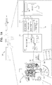
- FIG. 1A shows a firearm with a fire improving hit probability apparatus for reducing misfire of the firearm, according to some exemplary embodiments of the subject matter.
- the firearm 100 comprises a trigger 101, which enables firing of the firearm 100.
- the trigger 101 engages a sear box 103.
- the sear box 103 controls a rate of firing the firearm 100.
- the sear box 103 comprises a sear sensor 190 which is connected to the fire improving hit probability apparatus to monitor a sear movement of the sear box 103.
- the user of the firearm 100 selects which sear of the one or more sears controls a rate of firing of the firearm 100 according to how the user wishes to use the firearm 100.
- the fire improving hit probability apparatus 105 is connected to an interior or an exterior of the firearm 100, or may be constructed as a part of the firearm 100.
- the fire improving hit probability apparatus 105 comprises a trigger sensor 102, which is connected to the trigger 101.
- the trigger sensor 102 detects when the trigger 101 is engaged, for example, when a user of the firearm 100 presses the trigger 101.
- the trigger sensor 102 comprises a magnetic sensor that senses the location of the trigger 101 according to a small magnet (not shown) connected to trigger 101 near the trigger sensor 102.
- the small magnet is connected to components of a trigger mechanism (not shown) the sear box 103.
- the trigger sensor 102 measures the magnetic field of the magnet connected to the trigger 101 and determines the location of the trigger according to the values measured by the trigger sensor 102.
- a user of the firearm 100 engages the trigger 101 discharge a first round. After the first round is discharged, the fire improving hit probability apparatus 105 controls discharge of additional rounds until an end of firing condition occurs and the trigger 101 is no longer engaged. When the end of firing condition occurs and the trigger 101 is released the fire improving hit probability apparatus 105 resets. For example, the fire improving hit probability apparatus 105 receives a signal that the trigger sensor 102 no longer detects the trigger 101 is engaged, or that a predetermined number of rounds have been discharged from the firearm 100 after the first round.
- the detection unit 114 comprises a mechanical micro system (“MEMS") unit 115, which collects direction data.
- the direction data comprises of a direction at which the firearm 100 is directed.
- the MEMS unit 115 comprises an accelerometer 116, a gyroscope 117, a magnetometer 118 or a combination thereof to measure the direction data of the firearm 100.
- the accelerometer 116 is configured to measure an acceleration of a movement of the firearm, for example at a rate smaller than 400 hertz.
- the gyroscope 117 is configured to measure an angular velocity of the firearm, for example at a rate smaller than 760 hertz.
- the magnetometer 118 is configured to measure a direction of a magnetic field of the planet and where a barrel of the firearm 100 is relative to a magnetic north direction, for example at a rate smaller than 80 hertz.
- the MEMS unit 115 receives the information from the accelerometer 116, the gyroscope 117, the magnetometer 118 or the combination thereof and generates the direction data of the firearm 100.
- the direction data may be represented as a yaw, roll, and pitch of the firearm 100 at the time the first round is discharged. Such time may be the time the user presses the trigger 101 or a time substantially similar thereto.
- the trigger sensor 102 When the trigger sensor 102 detects that the trigger 101 is engaged, the trigger sensor 102 transfer a signal to the fire improving hit probability apparatus 105.
- the fire improving hit probability apparatus 105 records the direction data being measured by the MEMS unit 115 at the time the signal is received by the fire improving hit probability apparatus 105 and designates the direction data as a vector value.
- the fire improving hit probability apparatus 105 may comprise a storage 140 to store the vector value for the duration of time the vector value is required by the fire improving hit probability apparatus 105.
- the fire improving hit probability apparatus 105 is connected to a firing sensor 150, which is connected to the firearm 100. The firing sensor 150 detects when the firing a round from the firearm 100 has occurred by measuring the impact caused by the firing of the round.
- the firing sensor is a piezoelectric sensor.
- the fire improving hit probability apparatus 105 may require two separate conditions for designating the target direction data. A first condition is detection by the trigger sensor 102 that the trigger 101 is engaged and a second condition is detection by the firing sensor 150 that a firing impact occurred to the firearm 100.
- the fire improving hit probability apparatus 105 comprises a firing processor 110, which receives the direction data from the MEMs unit 115 and transfers the direction data to the storage 140 for storage.
- the firing processor 110 comprises a filtering unit 120, which filters the direction data and removes noise and other unwanted interferences.
- the filtering unit 120 comprises a direction algorithm, which may fuse data from various sensors, for example fusing data from the accelerometer 116 and the magnetometer 118.
- the user's accuracy may be improved by the fire improving hit probability apparatus 105 by referencing the firing of later rounds. The referencing may be determined by a separate algorithm stored in the fire improving hit probability apparatus 105, which tracks barrel direction of the firearm 100 to generate a plot of approximate solution for optimal and correct direction.
- the plot may then be displayed on a display (not shown), for example where the firearm 100 comprises a scope (not shown), the plot may be displayed in through the scope.
- the firing processor 110 obtains the direction data from the storage 140.
- the firing processor 110 designates the direction data obtained from the storage 140 as the vector value.
- the firing processor 110 compares the vector value with real time direction data to determine when the real time direction data matches the vector value.
- the fire improving hit probability apparatus 105 enables firing of the firearm 100.
- the detection unit 114 comprises an image capturing unit 130 to capture imaging data, which is used as the direction data.
- the image capturing unit 130 comprises a camera 131, which collects images of the direction at which the firearm 100 is directed. For example, where the firearm 100 is aimed in the direction of a target, the camera 131 records images of the target as a single or additional reference of the direction, the firearm 100 is directed in. Where the firearm 100 is aimed in the direction of a building, the camera 131 collects images of the building as the reference of the direction the firearm 100 is directed.
- the trigger unit 111 detects the trigger 101 is engaged, the trigger unit 111 transfers the signal to the firing processor 110 to obtain an image sample from the image capturing unit 130.
- the image sample may comprise an entire image collected by the image capturing unit 130 or a portion of the entire image, such as a predetermined number of pixels of the image.
- the firing processor 110 designates as the image sample 400 pixels from the top left of the image.
- the image sample is stored in the storage 140 and used to compare with new image data being captured by the image capturing unit 130 on a continuous basis, or on a periodical basis, for example at a rate of 50 Hertz.
- the firing processor 110 matches image sample with image data collected by the image capturing unit 130 the firing processor 110 engages a sear in the sear unit 103 to release the hammer 193 and fire a second round, such as the round 106.
- the fire improving hit probability apparatus 105 comprises a second trigger 121, for example as a push button. The user engages the trigger 101 and the second trigger 121 to enable the firearm to fire the round.
- the fire improving hit probability apparatus 105 comprises a transceiver 112, which is used to transmit the data, for example for storage in a server (not shown). In some case, the transceiver 112 is used to receive commands regarding the performance of the fire improving hit probability apparatus 105, for example to remotely turn on or off the fire improving hit probability apparatus 105.
- FIG. 1B shows a firing mechanism of the firearm 100 comprising the fire improving hit probability apparatus 105, according to some exemplary embodiments of the subject matter.
- the fire improving hit probability apparatus 105 comprises an electromagnet 197 connected to a sear 192 in the sear box 103.
- the electromagnet 197 controls the functions of the sear 192 when the fire improving hit probability apparatus 105 is activated and relays information to the firing processor 110, which controls the sear 192 by the methods disclosed herein.
- the fire improving hit probability apparatus 105 is not activated, the firearm 100 fires every time the shooter engages the trigger 101.
- an electromagnet 197 controls the sear 192 and the firearm 100 only fires when the fire improving hit probability apparatus 105 enables firing.
- the electromagnet 197 is connected to a Paramagnetic sear 196, which controls a lever 195.
- the electromagnet 197 may be configured as a normally open electromagnet or a normally closed electromagnet.
- the lever 195 enables or disables the sear 192 from releasing the hammer.
- the electromagnet 197 controls the Paramagnetic sear 196.
- the fire improving hit probability apparatus 105 sends a firing signal to the electromagnet 197
- the electromagnet 197 releases the Paramagnetic sear 196 and allows the sear 192 to release the hammer 193, which results in firing of the round 106.
- An assistance safety sear 194 enables firing the firearm 100 in a standard automatic manner when the fire improving hit probability apparatus 105 is disabled.
- an assistance safety sear 194 enables firing of the firearm 100 when the fire improving hit probability apparatus 105 is disabled.
- the assistance safety sear 194 may enable automatic firing of the firearm 100.
- FIG. 2 shows an environment of a firearm with a fire improving hit probability apparatus, according to some exemplary embodiments of the subject matter.
- the environment 200 comprises the firearm 201.
- the firearm 201 comprises a fire improving hit probability apparatus 202, which improves hit probability of the firearm 201.
- the fire improving hit probability apparatus 202 may be attached to the exterior or interior of the firearm 201. In some cases the fire improving hit probability apparatus 202 is constructed as part of the firearm 201.
- the fire improving hit probability apparatus 202 collects direction data of a direction in which the firearm 100 is directed.
- the fire improving hit probability apparatus 202 designates the vector value as the direction data collected by the fire improving hit probability apparatus 202 at the time the trigger 203 is pressed.
- the fire improving hit probability apparatus 202 prevents the firearm 201 from discharging a round unless new direction data collected matches the vector value.
- the fire improving hit probability apparatus 202 compares between direction data collected and the vector value. When the new direction data matches the vector value, the fire improving hit probability apparatus 202 enables the firearm 201 to discharge the round.
- the fire improving hit probability apparatus 202 may designate a firing safety boundary around the vector value.
- the firing safety boundary is a deviation area around the vector value in which the fire improving hit probability apparatus 202 may enable the firearm 201 to discharge the round.
- the fire improving hit probability apparatus 202 prevents the firearm 100 from firing.
- the firing safety boundary may be modified prior to use of the firearm 100, for example according to which user is firing the firearm 100 or whether the task is for different combat engagements.
- the user of the firearm may move the firearm 201 from a desired firing direction when pressing the trigger 203.
- the fire improving hit probability apparatus 202 analyzes direction data collected prior to the shooter engaging the trigger, for example the 300 milliseconds prior to the shooter pressing the trigger 203, and designate the vector value to be the direction data collected before pressing the trigger for the first round fired.
- the fire improving hit probability apparatus 202 transmits firing data to a computerized device 240 or a mobile device 250, such as a tablet or smartphone.
- the firing data may comprise, the number of rounds discharged from the firearm 201 at a designated direction, the length of time required by the shooter to realign the firearm 201 in the designated direction, or the like.
- the firing data may enable a third party to monitor firing patterns of the shooter firing the firearm 201 and provide instructive assistance and training to the shooter to improve reaction time and firing performance.
- the fire improving hit probability apparatus 202 may communicate with the computerized device 240 or a mobile device 250 through near field communication, Bluetooth, or the like.
- the third party may then provide instruction to the user of the firearm on how to improve the use of the firearm 201.
- the fire improving hit probability apparatus 202 may transmit the firing data to a server 230, to enable storing the firing data and providing access to the firing data at a later time.
- the server 230 may be accessed by the computerized device 240 or the mobile device 250 a World Wide Web (“WWW”) 260 and enables sharing of the firing data through a website on the WWW 260, a file sharing protocol (“FTP”), or the like.
- WWW World Wide Web
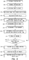
- FIG 3 shows a method performed by a fire improving hit probability apparatus to improve a hitting probability of a user of a firearm, according to some exemplary embodiments of the subject matter.
- Step 300 discloses the fire improving hit probability apparatus 105 of Figure 1 obtaining direction data.
- the detection unit 114 of Figure 1 obtains direction data.
- the detection unit 114 comprises the MEMs unit 115 of Figure 1 , which comprises the accelerometer 116 of Figure 1 , the gyroscope 117 of Figure 1 , the magnetometer 118 of Figure 1 or a combination thereof.
- the MEMs unit 115 obtains the direction data as values of pitch, roll and yawl, as is further described herein above in connection with the description of the other figures.
- the direction data is obtained in the form of image data, which is recorded by the image capturing unit 130 of Figure 1 .
- the detection unit 114 transfers the direction data to the fire improving hit probability apparatus 105 as the direction data is collected.
- Step 305 discloses the fire improving hit probability apparatus 105 storing the direction data.
- the firing processor 110 of Figure 1 transfers the direction data to the storage 140 of Figure 1 to be stored.
- the direction data is stored for a predetermined amount of time, after which time the direction data is deleted from the storage 140 to preserve space in the storage 140 for later use. For example, the firing processor 110 deletes stored direction data from the storage every 1-5 seconds.
- Step 310 discloses the fire improving hit probability apparatus 105 detecting a trigger activity.
- the trigger sensor 102 of Figure 1 detects when the trigger 101 of Figure 1 is engaged by the user of the firearm 100.
- the trigger sensor 102 detects the trigger 101 is engaged, the trigger sensor 102 sends a signal to the firing processor 110 to inform the firing processor 110 that the trigger 101 is engaged.
- the trigger sensor 102 comprises a magnetic sensor that measures the strength of a magnetic field created by the movement of the trigger 101 to the trigger sensor 102.
- a magnet is embedded in the trigger 101 such that the magnet's motion creates a change in the magnetic field measured by the trigger sensor 102.
- the trigger sensor 102 measures a rise in the magnetic field which signals that the trigger 101 is engaged, and a decrease in the magnetic field signals the trigger 101 is released.
- Step 315 discloses the fire improving hit probability apparatus 105 detecting a firing of a first round from the firearm 100.
- the fire improving hit probability apparatus 105 comprises the firing sensor 150 of Figure 1 , which detects when a round is fired from the firearm 100.
- the firing sensor 150 which in some cases is a piezoelectric sensor, measures the impact to the firearm 100 to confirm that the round was fired.
- the firearm 100 engages the trigger 101 the firearm 100 fires the first round in a direction that the user aimed the firearm 100.
- the firing sensor 150 detects the firing of the first round.
- the firing sensor 150 is connected to a hammer of the firearm 100 to detect the motion of the hammer to enable determining a firing of the firearm 100 occurred.
- Step 320 discloses the fire improving hit probability apparatus 105 calculating a vector value.
- the vector value comprises direction data the fire improving hit probability apparatus uses to determine when the firearm 100 is aimed at in a desired direction to enable firing of the firearm 100.
- the firing processor 110 calculates the vector value when the firing sensor 150 detects the first round is fired.
- the firing processor 110 must receive be informed by the trigger sensor 102 that the trigger 101 is engaged and that the firing sensor 150 detected the firing of the first round before calculating the vector value.
- the trigger sensor 102 may detect the motion of the trigger 101 such that different signals are sent to the firing processor 110 according to the location of the trigger 101. For example, when the trigger 101 is half engaged the trigger sensor 102 transmits a first signal where the firing processor 110 obtains the vector value without discharging the first round. When the trigger 101 is then fully engaged the firearm 100 does not discharge the first round until the firing processor 110 enables firing of the first round. In some cases, the firing processor 110 designates direction data obtained when the first round is fired as the vector value.
- the calculation comprises assigning an array of values to designate a target window surrounding the vector value.
- the firing processor 110 designates the target window
- the firing processor enables firing of the firearm when real time direction data matches any value of the array.
- the target window may comprise a different array size according to the type of firearm 100 being fired, the experience of the user, and the like.
- the firing processor 110 calculates a central direction point according to the direction data collected by the detection unit 114.
- the central direction point is an algorithmic determination of a direction in which a user of the firearm was aiming the firearm prior to engaging the trigger to fire a first round.
- the user of the firearm 100 is not well trained in firing the firearm 100 and may miss a target due to inexperience, stress, a distraction, or the like.
- the firing processor 110 designates the central direction point as the vector value, which is direction data stored in the storage 140 at some predetermined time prior to engagement of the trigger 101 and detection of the firing of the first round.
- the firing processor 110 designates the vector value as the direction data collected by the detection unit 114 fifty milliseconds prior to detection of engagement of the trigger 101 and firing of the first round. Designation of direction data from some predetermined time as the vector value provides for a more accurate vector value due to a higher likelihood the user had a better aim prior to engaging the trigger 101.
- the firing processor 110 designates the central direction point according to direction data obtained over a predetermined time range occurring some predetermined time prior to detection of engagement of the trigger 101 and of firing of the first round. For example, the firing processor 110 analyzes the direction data of a one second period prior to detection of trigger engagement and firing of the first round. The firing processor 110 analyzes the direction data stored in the storage 140 to determine the direction data that is most collected in the time period prior to detection of the trigger engagement and firing of the first round.
- Step 325 discloses the fire improving hit probability apparatus 105 comparing the vector value with real time direction data.
- the firing processor 110 compares the direction data of the vector value with direction data obtained in real time, while the user is aiming the firearm 100.
- the direction data comprises data obtained by the MEMs unit 115
- the firing processor 110 compares the pitch, role, and yawl, of the vector value is compared to the pitch, role, and yawl of the direction data obtained in real time.
- the firing processor 110 may compare pixels from the vector value with pixels from the direction data obtained in real time.
- Step 328 discloses the fire improving hit probability apparatus 105 designating a passing zone.
- the comparison is performed for the passing zone, which comprises direction data within a predetermined range in which the fire improving hit probability apparatus 105 enables firing of the firearm 100.
- Designating the passing zone creates comprise between accuracy and speed of firing of the fire improving hit probability apparatus 105.
- the firing processor 110 designates the passing zone according a predetermined range, for example, the passing zone comprising an area of a circle with a 10 mili-radian.
- Step 329 discloses the fire improving hit probability apparatus 105 designating a firing safety boundary.
- the firing processor 110 designates the firing safety boundary as a predetermined distance from the vector value.
- the detection unit 114 collects direction data that is greater than the firing safety boundary, the firing processor 110 stops firing and the user of the firearm 100 must release the trigger and designate a new vector value.
- the firing safety boundary is where the firearm 100 is aimed 10 degrees relative to any direction away from the vector value.
- Step 330 discloses the fire improving hit probability apparatus 105 determining the vector value matches direction data of the barrel obtained in real time.
- the firing processor 110 determines that the direction data obtained in real time matches the vector value.
- the firing processor 110 determines there is a match where the direction data obtained in real time is within the passing zone.
- Step 335 discloses the fire improving hit probability apparatus 105 firing the firearm 100.
- the firing processor 110 sends a signal to the electromagnet 197 of Figure 1B to release the Paramagnetic sear196 of Figure 1 .
- the electromagnet 197 may be a replaced by a solenoid or a mechanical motor that control the hammer 193 or the sear
- Step 340 discloses the fire improving hit probability apparatus 105 determining whether an end of firing condition occurred.
- the firing processor 110 comprises a plurality of end of firing commands which prevent the firearm 100 from firing until the trigger 101 is released and the fire improving hit probability apparatus 105 resets.
- the end of firing command is the firing of a predetermined number of consecutive rounds, for example, five rounds.
- the end of firing command is a lapse of a predetermined waiting time in which no firing occurs. For example, where the firing processor 110 cannot match the direction data obtained in real time with the vector value for longer than 3 seconds the firing processor 110 flags the end of firing command. In other cases, the firing processor 110 flags the end of firing command where the direction data collected in real time is exceeds the value of the firing safety boundary.
- the firing processor 110 flags the end of firing command. In cases where the fire improving hit probability apparatus 105 determines that an end of firing condition did not occur, the fire improving hit probability apparatus 105 returns to step 325. In cases where the fire improving hit probability apparatus 105 determines that an end of firing condition did occur, the fire improving hit probability apparatus 105 performs step 345 of flagging an end of firing condition has occurred.
- Step 350 discloses the fire improving hit probability apparatus 105 detecting a release of the trigger 101.
- the firing processor 110 waits for release of the trigger 101 to enable resetting of the fire improving hit probability apparatus 105.
- Step 360 discloses the fire improving hit probability apparatus 105 resetting to obtain a new vector value. Once the end of firing condition is flagged and the trigger 101 is disengaged, the firing processor 1 10 resets the fire improving hit probability apparatus 105 to obtain a new vector value.
Landscapes
- Engineering & Computer Science (AREA)
- General Engineering & Computer Science (AREA)
- Physics & Mathematics (AREA)
- Optics & Photonics (AREA)
- Aiming, Guidance, Guns With A Light Source, Armor, Camouflage, And Targets (AREA)
Description
- The subject matter relates generally to an apparatus and method for improving hit probability of a user of a firearm, improve the user's control of the weapon, and maintaining fire for longer periods.
- Using a firearm requires skill and practice. A user of a firearm has to be in control of the firearm to ensure that rounds fired are fired at a desired target. In some of the situations, the goal of firing a round is not to hit a desired target, but rather to cause an opponent to seek cover or to prevent return fire. Users of firearms, in such situations, would typically be under significant stress. Therefore, there is a high chance that the user of the firearm will shoot in a wrong direction due to fear, anxiety, or the like. After firing the round, it takes the user of the firearm a relatively long time to reposition the firearm so as to be aimed at a target and to release another round in the direction of the first round.
- Modern firearms, such as machine guns, are typically designed to have at least two modes of firing: single round and automatic. The single round mode is also referred to as semi-automatic mode. Users of firearm in combat or like situations commonly have the firearm set to single round and more rarely to automatic. When additional firepower is required, users of the firearm may switch the firearm to automatic mode or would use semi-automatic mode to fire rapidly producing a rapid-fire effect. Users lacking experience may misfire and continue pressing a firearm trigger, leading to a waste of ammunition and increasing a risk of collateral damage.
- "Patent document
US 2002/0174588 A1 describes a sensor system for detecting jarring, acceleration or other application of force to a firearm, and/or movement of the firearm into an undesired orientation. Said system is adapted to prevent firing of the firearm when the firearm is within said undesired orientation but it does not address the issue of improving the hit probability following the firing of a first round." - It is an object of the subject matter to disclose a fire improving hit probability apparatus for reducing misfire of a firearm, said apparatus comprising :
- a trigger unit to detect when a trigger of the firearm is engaged;
- a detection unit to collect direction data of a direction at which the firearm is directed when the trigger of the firearm is engaged; said trigger engagement results in firing of a first round from the firearm,
- a firing processor to improve accuracy (i.e. hit probability) of a shooter firing the firearm, said firing processor being configured to: designate a vector value (i.e. target sample) when the firing processor receives a signal from the trigger unit that the trigger is engaged, wherein the vector value (i.e. target sample) comprises the direction data;
- a storage for storing an orientation sample designated by the firing processor;
- an electromagnet to control functions of a sear of the firearm.
- The firing processor is adapted to :
- designate a target orientation data according to orientation data collected when the trigger is engaged,
- compare said target orientation data to a real time orientation data;
- enable firing of the firearm when the vector value (i.e. real time orientation data) matches the real time direction (i.e. target orientation data) within a passing zone.
- In some cases the firing processor determines a center of mass according to the orientation data collected prior to engagement of the trigger, said center of mass is an algorithmic determination of an orientation direction in which a user of the firearm was aiming the firearm prior to engaging the trigger to fire a first round.
- In some cases, the detection unit comprises a mechanical micro system unit that measures the orientation data; wherein the firing processor designates an orientation sample as the target sample; wherein the orientation sample comprises the orientation data; wherein the firing processor is configured to compare the orientation sample with the real time orientation data measured by a mechanical micro system unit.
- In some cases, the firing processor is configured to designate a target window in which the firearm discharges the round.
- In some cases, the firing processor is configured to designate a passing zone.
- In some cases, the detection unit comprises an image capturing unit, to collect image data; wherein the firing processor is configured to designate an image sample as the target sample; wherein the image sample is compared to a new image data collected by the image capturing unit.
- In some cases, the fire improving hit probability apparatus further comprises a transceiver to transmit data to a computerized device, a mobile device, a server, or a combination thereof.
- In some cases, the firing processor resets the fire improving hit probability apparatus when the trigger is disengaged.
- In some cases, the electromagnet is a normally open electromagnet.
- In some cases, the electromagnet is a normally closed electromagnet.
- In some cases, the electromagnet is replaced by a mechanical motor.
- In some cases, the electromagnet is replaced by a solenoid.
- Another objective of the subject matter is to disclose a method performed by a fire aim improving hit probability apparatus for improving hit probability of a firearm, said method comprising
- obtaining a a detection of an engagement of a trigger; wherein the engagement is detected by a trigger unit of the fire improving hit probability apparatus, said trigger engagement resulting in firing of a first round from the firearm ;
- designating a vector value (i.e target sample) from a detection unit of the fire aim improving hit probability apparatus; wherein the vector value (i.e. target sample) is direction data collected by the detection unit; wherein a firing processor of the fire aim improving hit probability apparatus designates the vector value (i.e. target sample) when the firing processor receives a signal from the trigger unit that the trigger was engaged;
- storing the vector value (i.e. target sample) in a storage of the fire aim improving hit probability apparatus;
- comparing, by the firing processor, the vector value (i.e. target sample) with real time direction data (i.e. new direction data); wherein the real time direction data (i.e; new direction data) is received from the detection unit;
- enabling, by the firing processor, the firing of the firearm when the vector value (i.e. target sample) matches the new direction data inside a passing zone; and
- controlling functions of a sear of the firearm using a electromagnet.
- In some cases, the method further comprises calculating a direction data (i.e. target orientation data), wherein a central direction point (i.e. center of mass) is designated to the target orientation data by the firing processor, said center of mass is the target sample stored in the storage of the fire improving hit probability apparatus at some predetermined time prior to the engagement of the trigger and detection of the firing of the first round.
- In some cases, the method further comprises designating the passing zone of the direction (orientation) data within a predetermined range, said passing zone enables the firearm to discharge the predetermined range.
- In some cases, the method further comprises resetting the fire improving hit probability apparatus.
- In some cases, the fire improving hit probability apparatus is reset when the trigger is disengaged.
- In some cases, the fire improving hit probability apparatus is reset when a predetermined number of rounds have been discharged from the firearm.
- In some cases, the fire improving hit probability apparatus is reset after a predetermined waiting time has lapsed.
- In some cases, the method further comprises designating a firing safety boundary according to the vector value (i.e. target sample).
- Exemplary non-limited embodiments of the disclosed subject matter will be described, with reference to the following description of the embodiments, in conjunction with the figures. The figures are generally not shown to scale and any sizes are only meant to be exemplary and not necessarily limiting. Corresponding or like elements are optionally designated by the same numerals or letters.
-
Figures 1A-1B show a firearm with a firing control apparatus for improving hit probability of user firing the firearm, according to some exemplary embodiments of the subject matter; -
Figure 2 shows an environment of a firearm with a fire improving hit probability apparatus, according to some exemplary embodiments of the subject matter; and, -
Figure 3 shows a method performed by a fire improving hit probability apparatus to improve a hitting probability of a user of a firearm, according to some exemplary embodiments of the subject matter. - The subject matter relates generally to a method and apparatus for reducing misfire of a firearm, improve the user's control of the weapon, and maintaining fire for longer periods, according to exemplary embodiments of the subject matter.
-
Figure 1A shows a firearm with a fire improving hit probability apparatus for reducing misfire of the firearm, according to some exemplary embodiments of the subject matter. Thefirearm 100 comprises atrigger 101, which enables firing of thefirearm 100. Thetrigger 101 engages asear box 103. Thesear box 103 controls a rate of firing thefirearm 100. For example, thesear box 103 comprises asear sensor 190 which is connected to the fire improving hit probability apparatus to monitor a sear movement of thesear box 103. The user of thefirearm 100 selects which sear of the one or more sears controls a rate of firing of thefirearm 100 according to how the user wishes to use thefirearm 100. The fire improving hitprobability apparatus 105 is connected to an interior or an exterior of thefirearm 100, or may be constructed as a part of thefirearm 100. The fire improving hitprobability apparatus 105 comprises atrigger sensor 102, which is connected to thetrigger 101. Thetrigger sensor 102 detects when thetrigger 101 is engaged, for example, when a user of thefirearm 100 presses thetrigger 101. In some cases, thetrigger sensor 102 comprises a magnetic sensor that senses the location of thetrigger 101 according to a small magnet (not shown) connected to trigger 101 near thetrigger sensor 102. In some cases, the small magnet is connected to components of a trigger mechanism (not shown) thesear box 103. Thetrigger sensor 102 measures the magnetic field of the magnet connected to thetrigger 101 and determines the location of the trigger according to the values measured by thetrigger sensor 102. A user of thefirearm 100 engages thetrigger 101 discharge a first round. After the first round is discharged, the fire improving hitprobability apparatus 105 controls discharge of additional rounds until an end of firing condition occurs and thetrigger 101 is no longer engaged. When the end of firing condition occurs and thetrigger 101 is released the fire improving hitprobability apparatus 105 resets. For example, the fire improving hitprobability apparatus 105 receives a signal that thetrigger sensor 102 no longer detects thetrigger 101 is engaged, or that a predetermined number of rounds have been discharged from thefirearm 100 after the first round. - When the
trigger sensor 102 detects thetrigger 101 is engaged, thetrigger sensor 102 transfers a command to the fire improving hitprobability apparatus 105 to obtain a direction data from adetection unit 114. Thedetection unit 114 comprises a mechanical micro system ("MEMS")unit 115, which collects direction data. The direction data comprises of a direction at which thefirearm 100 is directed. TheMEMS unit 115 comprises anaccelerometer 116, agyroscope 117, amagnetometer 118 or a combination thereof to measure the direction data of thefirearm 100. Theaccelerometer 116 is configured to measure an acceleration of a movement of the firearm, for example at a rate smaller than 400 hertz. Thegyroscope 117 is configured to measure an angular velocity of the firearm, for example at a rate smaller than 760 hertz. Themagnetometer 118 is configured to measure a direction of a magnetic field of the planet and where a barrel of thefirearm 100 is relative to a magnetic north direction, for example at a rate smaller than 80 hertz. TheMEMS unit 115 receives the information from theaccelerometer 116, thegyroscope 117, themagnetometer 118 or the combination thereof and generates the direction data of thefirearm 100. The direction data may be represented as a yaw, roll, and pitch of thefirearm 100 at the time the first round is discharged. Such time may be the time the user presses thetrigger 101 or a time substantially similar thereto. When thetrigger sensor 102 detects that thetrigger 101 is engaged, thetrigger sensor 102 transfer a signal to the fire improving hitprobability apparatus 105. The fire improving hitprobability apparatus 105 records the direction data being measured by theMEMS unit 115 at the time the signal is received by the fire improving hitprobability apparatus 105 and designates the direction data as a vector value. The fire improving hitprobability apparatus 105 may comprise astorage 140 to store the vector value for the duration of time the vector value is required by the fire improving hitprobability apparatus 105. In some exemplary embodiments of the subject matter, the fire improving hitprobability apparatus 105 is connected to afiring sensor 150, which is connected to thefirearm 100. The firingsensor 150 detects when the firing a round from thefirearm 100 has occurred by measuring the impact caused by the firing of the round. For example, the firing sensor is a piezoelectric sensor. In such cases, the fire improving hitprobability apparatus 105 may require two separate conditions for designating the target direction data. A first condition is detection by thetrigger sensor 102 that thetrigger 101 is engaged and a second condition is detection by the firingsensor 150 that a firing impact occurred to thefirearm 100. - The fire improving hit
probability apparatus 105 comprises afiring processor 110, which receives the direction data from theMEMs unit 115 and transfers the direction data to thestorage 140 for storage. The firingprocessor 110 comprises afiltering unit 120, which filters the direction data and removes noise and other unwanted interferences. Thefiltering unit 120 comprises a direction algorithm, which may fuse data from various sensors, for example fusing data from theaccelerometer 116 and themagnetometer 118. In some cases, the user's accuracy may be improved by the fire improving hitprobability apparatus 105 by referencing the firing of later rounds. The referencing may be determined by a separate algorithm stored in the fire improving hitprobability apparatus 105, which tracks barrel direction of thefirearm 100 to generate a plot of approximate solution for optimal and correct direction. The plot may then be displayed on a display (not shown), for example where thefirearm 100 comprises a scope (not shown), the plot may be displayed in through the scope. When the fire improving hitprobability apparatus 105 receives a signal to designate the vector value, the firingprocessor 110 obtains the direction data from thestorage 140. The firingprocessor 110 designates the direction data obtained from thestorage 140 as the vector value. The firingprocessor 110 compares the vector value with real time direction data to determine when the real time direction data matches the vector value. When firingprocessor 110 matches the real time direction data matches the vector value, the fire improving hitprobability apparatus 105 enables firing of thefirearm 100. - In some exemplary embodiments of the subject matter the
detection unit 114 comprises animage capturing unit 130 to capture imaging data, which is used as the direction data. Theimage capturing unit 130 comprises acamera 131, which collects images of the direction at which thefirearm 100 is directed. For example, where thefirearm 100 is aimed in the direction of a target, thecamera 131 records images of the target as a single or additional reference of the direction, thefirearm 100 is directed in. Where thefirearm 100 is aimed in the direction of a building, thecamera 131 collects images of the building as the reference of the direction thefirearm 100 is directed. When the trigger unit 111 detects thetrigger 101 is engaged, the trigger unit 111 transfers the signal to thefiring processor 110 to obtain an image sample from theimage capturing unit 130. The image sample may comprise an entire image collected by theimage capturing unit 130 or a portion of the entire image, such as a predetermined number of pixels of the image. For example, the firingprocessor 110 designates as the image sample 400 pixels from the top left of the image. The image sample is stored in thestorage 140 and used to compare with new image data being captured by theimage capturing unit 130 on a continuous basis, or on a periodical basis, for example at a rate of 50 Hertz. When the firingprocessor 110 matches image sample with image data collected by theimage capturing unit 130 the firingprocessor 110 engages a sear in thesear unit 103 to release thehammer 193 and fire a second round, such as theround 106. - In some exemplary embodiments of the subject matter, the fire improving hit
probability apparatus 105 comprises asecond trigger 121, for example as a push button. The user engages thetrigger 101 and thesecond trigger 121 to enable the firearm to fire the round. In some exemplary embodiments of the subject matter, the fire improving hitprobability apparatus 105 comprises atransceiver 112, which is used to transmit the data, for example for storage in a server (not shown). In some case, thetransceiver 112 is used to receive commands regarding the performance of the fire improving hitprobability apparatus 105, for example to remotely turn on or off the fire improving hitprobability apparatus 105. -
Figure 1B shows a firing mechanism of thefirearm 100 comprising the fire improving hitprobability apparatus 105, according to some exemplary embodiments of the subject matter. The fire improving hitprobability apparatus 105 comprises anelectromagnet 197 connected to a sear 192 in thesear box 103. Theelectromagnet 197 controls the functions of the sear 192 when the fire improving hitprobability apparatus 105 is activated and relays information to thefiring processor 110, which controls the sear 192 by the methods disclosed herein. When the fire improving hitprobability apparatus 105 is not activated, thefirearm 100 fires every time the shooter engages thetrigger 101. Where the fire improving hitprobability apparatus 105 is activated, anelectromagnet 197 controls the sear 192 and thefirearm 100 only fires when the fire improving hitprobability apparatus 105 enables firing. Theelectromagnet 197 is connected to aParamagnetic sear 196, which controls alever 195. Theelectromagnet 197 may be configured as a normally open electromagnet or a normally closed electromagnet. Thelever 195 enables or disables the sear 192 from releasing the hammer. Theelectromagnet 197 controls theParamagnetic sear 196. When the fire improving hitprobability apparatus 105 sends a firing signal to theelectromagnet 197, theelectromagnet 197 releases the Paramagnetic sear 196 and allows the sear 192 to release thehammer 193, which results in firing of theround 106. Anassistance safety sear 194 enables firing thefirearm 100 in a standard automatic manner when the fire improving hitprobability apparatus 105 is disabled. In some cases, anassistance safety sear 194 enables firing of thefirearm 100 when the fire improving hitprobability apparatus 105 is disabled. Theassistance safety sear 194 may enable automatic firing of thefirearm 100. -
Figure 2 shows an environment of a firearm with a fire improving hit probability apparatus, according to some exemplary embodiments of the subject matter. The environment 200 comprises thefirearm 201. Thefirearm 201 comprises a fire improving hitprobability apparatus 202, which improves hit probability of thefirearm 201. The fire improving hitprobability apparatus 202 may be attached to the exterior or interior of thefirearm 201. In some cases the fire improving hitprobability apparatus 202 is constructed as part of thefirearm 201. The fire improving hitprobability apparatus 202 collects direction data of a direction in which thefirearm 100 is directed. When a user of thefirearm 201 engages atrigger 203, the fire improving hitprobability apparatus 202 designates the vector value as the direction data collected by the fire improving hitprobability apparatus 202 at the time thetrigger 203 is pressed. While thetrigger 203 remains engaged, the fire improving hitprobability apparatus 202 prevents thefirearm 201 from discharging a round unless new direction data collected matches the vector value. The fire improving hitprobability apparatus 202 compares between direction data collected and the vector value. When the new direction data matches the vector value, the fire improving hitprobability apparatus 202 enables thefirearm 201 to discharge the round. The fire improving hitprobability apparatus 202 may designate a firing safety boundary around the vector value. The firing safety boundary is a deviation area around the vector value in which the fire improving hitprobability apparatus 202 may enable thefirearm 201 to discharge the round. When thefirearm 201 is aimed outside of the firing boundaries, the fire improving hitprobability apparatus 202 prevents thefirearm 100 from firing. In some exemplary embodiments of the subject matter, the firing safety boundary may be modified prior to use of thefirearm 100, for example according to which user is firing thefirearm 100 or whether the task is for different combat engagements. - In some exemplary embodiments of the subject matter, the user of the firearm, due to stress, inexperience, or the like, may move the
firearm 201 from a desired firing direction when pressing thetrigger 203. The fire improving hitprobability apparatus 202 analyzes direction data collected prior to the shooter engaging the trigger, for example the 300 milliseconds prior to the shooter pressing thetrigger 203, and designate the vector value to be the direction data collected before pressing the trigger for the first round fired. - In some exemplary embodiments of the subject matter, the fire improving hit
probability apparatus 202 transmits firing data to acomputerized device 240 or amobile device 250, such as a tablet or smartphone. The firing data may comprise, the number of rounds discharged from thefirearm 201 at a designated direction, the length of time required by the shooter to realign thefirearm 201 in the designated direction, or the like. The firing data may enable a third party to monitor firing patterns of the shooter firing thefirearm 201 and provide instructive assistance and training to the shooter to improve reaction time and firing performance. The fire improving hitprobability apparatus 202 may communicate with thecomputerized device 240 or amobile device 250 through near field communication, Bluetooth, or the like. The third party may then provide instruction to the user of the firearm on how to improve the use of thefirearm 201. In some cases, the fire improving hitprobability apparatus 202 may transmit the firing data to aserver 230, to enable storing the firing data and providing access to the firing data at a later time. Theserver 230 may be accessed by thecomputerized device 240 or the mobile device 250 a World Wide Web ("WWW") 260 and enables sharing of the firing data through a website on theWWW 260, a file sharing protocol ("FTP"), or the like. -
Figure 3 shows a method performed by a fire improving hit probability apparatus to improve a hitting probability of a user of a firearm, according to some exemplary embodiments of the subject matter. Step 300 discloses the fire improving hitprobability apparatus 105 ofFigure 1 obtaining direction data. Thedetection unit 114 ofFigure 1 obtains direction data. In some exemplary embodiments of the subject matter, thedetection unit 114 comprises theMEMs unit 115 ofFigure 1 , which comprises theaccelerometer 116 ofFigure 1 , thegyroscope 117 ofFigure 1 , themagnetometer 118 ofFigure 1 or a combination thereof. TheMEMs unit 115 obtains the direction data as values of pitch, roll and yawl, as is further described herein above in connection with the description of the other figures. In some exemplary embodiments of the subject matter, the direction data is obtained in the form of image data, which is recorded by theimage capturing unit 130 ofFigure 1 . Thedetection unit 114 transfers the direction data to the fire improving hitprobability apparatus 105 as the direction data is collected. - Step 305 discloses the fire improving hit
probability apparatus 105 storing the direction data. The firingprocessor 110 ofFigure 1 transfers the direction data to thestorage 140 ofFigure 1 to be stored. In some cases, the direction data is stored for a predetermined amount of time, after which time the direction data is deleted from thestorage 140 to preserve space in thestorage 140 for later use. For example, the firingprocessor 110 deletes stored direction data from the storage every 1-5 seconds. - Step 310 discloses the fire improving hit
probability apparatus 105 detecting a trigger activity. Thetrigger sensor 102 ofFigure 1 detects when thetrigger 101 ofFigure 1 is engaged by the user of thefirearm 100. When thetrigger sensor 102 detects thetrigger 101 is engaged, thetrigger sensor 102 sends a signal to thefiring processor 110 to inform thefiring processor 110 that thetrigger 101 is engaged. In some nonlimiting cases, thetrigger sensor 102 comprises a magnetic sensor that measures the strength of a magnetic field created by the movement of thetrigger 101 to thetrigger sensor 102. In such cases, a magnet is embedded in thetrigger 101 such that the magnet's motion creates a change in the magnetic field measured by thetrigger sensor 102. For example, when thetrigger 101 is engaged, thetrigger sensor 102 measures a rise in the magnetic field which signals that thetrigger 101 is engaged, and a decrease in the magnetic field signals thetrigger 101 is released. - Step 315 discloses the fire improving hit
probability apparatus 105 detecting a firing of a first round from thefirearm 100. When thetrigger 101 is engaged by the user, thefirearm 100 fires the first round. The fire improving hitprobability apparatus 105 comprises the firingsensor 150 ofFigure 1 , which detects when a round is fired from thefirearm 100. The firingsensor 150, which in some cases is a piezoelectric sensor, measures the impact to thefirearm 100 to confirm that the round was fired. When the user of thefirearm 100 engages thetrigger 101 thefirearm 100 fires the first round in a direction that the user aimed thefirearm 100. The firingsensor 150 detects the firing of the first round. In some exemplary cases, the firingsensor 150 is connected to a hammer of thefirearm 100 to detect the motion of the hammer to enable determining a firing of thefirearm 100 occurred. - Step 320 discloses the fire improving hit
probability apparatus 105 calculating a vector value. After thefiring processor 110 is informed by thetrigger sensor 102 that thetrigger 101 is engaged thefiring processor 110 calculates the vector value. The vector value comprises direction data the fire improving hit probability apparatus uses to determine when thefirearm 100 is aimed at in a desired direction to enable firing of thefirearm 100. In some cases, the firingprocessor 110 calculates the vector value when the firingsensor 150 detects the first round is fired. In other cases, the firingprocessor 110 must receive be informed by thetrigger sensor 102 that thetrigger 101 is engaged and that the firingsensor 150 detected the firing of the first round before calculating the vector value. In some exemplary embodiments of the subject matter, thetrigger sensor 102 may detect the motion of thetrigger 101 such that different signals are sent to thefiring processor 110 according to the location of thetrigger 101. For example, when thetrigger 101 is half engaged thetrigger sensor 102 transmits a first signal where the firingprocessor 110 obtains the vector value without discharging the first round. When thetrigger 101 is then fully engaged thefirearm 100 does not discharge the first round until the firingprocessor 110 enables firing of the first round. In some cases, the firingprocessor 110 designates direction data obtained when the first round is fired as the vector value. - In some exemplary embodiments of the subject matter, the calculation comprises assigning an array of values to designate a target window surrounding the vector value. Where the firing
processor 110 designates the target window, the firing processor enables firing of the firearm when real time direction data matches any value of the array. In some cases, the target window may comprise a different array size according to the type offirearm 100 being fired, the experience of the user, and the like. - In some exemplary embodiments of the subject matter, the firing
processor 110 calculates a central direction point according to the direction data collected by thedetection unit 114. The central direction point is an algorithmic determination of a direction in which a user of the firearm was aiming the firearm prior to engaging the trigger to fire a first round. In some cases, the user of thefirearm 100 is not well trained in firing thefirearm 100 and may miss a target due to inexperience, stress, a distraction, or the like. In such cases, the firingprocessor 110 designates the central direction point as the vector value, which is direction data stored in thestorage 140 at some predetermined time prior to engagement of thetrigger 101 and detection of the firing of the first round. For example, the firingprocessor 110 designates the vector value as the direction data collected by thedetection unit 114 fifty milliseconds prior to detection of engagement of thetrigger 101 and firing of the first round. Designation of direction data from some predetermined time as the vector value provides for a more accurate vector value due to a higher likelihood the user had a better aim prior to engaging thetrigger 101. - In some exemplary embodiments of the subject matter, the firing
processor 110 designates the central direction point according to direction data obtained over a predetermined time range occurring some predetermined time prior to detection of engagement of thetrigger 101 and of firing of the first round. For example, the firingprocessor 110 analyzes the direction data of a one second period prior to detection of trigger engagement and firing of the first round. The firingprocessor 110 analyzes the direction data stored in thestorage 140 to determine the direction data that is most collected in the time period prior to detection of the trigger engagement and firing of the first round. - Step 325 discloses the fire improving hit
probability apparatus 105 comparing the vector value with real time direction data. After thefiring processor 110 designates the vector value, the firingprocessor 110 compares the direction data of the vector value with direction data obtained in real time, while the user is aiming thefirearm 100. In cases where the direction data comprises data obtained by theMEMs unit 115, the firingprocessor 110 compares the pitch, role, and yawl, of the vector value is compared to the pitch, role, and yawl of the direction data obtained in real time. In cases where the direction data comprises data obtained by theimage capturing unit 130, the firingprocessor 110 may compare pixels from the vector value with pixels from the direction data obtained in real time. - Step 328 discloses the fire improving hit
probability apparatus 105 designating a passing zone. In some exemplary embodiments of the subject matter, the comparison is performed for the passing zone, which comprises direction data within a predetermined range in which the fire improving hitprobability apparatus 105 enables firing of thefirearm 100. Designating the passing zone creates comprise between accuracy and speed of firing of the fire improving hitprobability apparatus 105. The firingprocessor 110 designates the passing zone according a predetermined range, for example, the passing zone comprising an area of a circle with a 10 mili-radian. - Step 329 discloses the fire improving hit
probability apparatus 105 designating a firing safety boundary. The firingprocessor 110 designates the firing safety boundary as a predetermined distance from the vector value. When thedetection unit 114 collects direction data that is greater than the firing safety boundary, the firingprocessor 110 stops firing and the user of thefirearm 100 must release the trigger and designate a new vector value. For example the firing safety boundary is where thefirearm 100 is aimed 10 degrees relative to any direction away from the vector value. - Step 330 discloses the fire improving hit
probability apparatus 105 determining the vector value matches direction data of the barrel obtained in real time. When the firingprocessor 110 determines that the direction data obtained in real time matches the vector value. In some exemplary embodiments of the subject matter, the firingprocessor 110 determines there is a match where the direction data obtained in real time is within the passing zone. - Step 335 discloses the fire improving hit
probability apparatus 105 firing thefirearm 100. The firingprocessor 110 sends a signal to theelectromagnet 197 ofFigure 1B to release the Paramagnetic sear196 ofFigure 1 . When the Paramagnetic sear196 is released, the sear 192 ofFigure 1B releases thehammer 193 ofFigure 1B . Release of thehammer 193 results in the firing of a round from thefirearm 100. In some cases, theelectromagnet 197 may be a replaced by a solenoid or a mechanical motor that control thehammer 193 or the sear - Step 340 discloses the fire improving hit
probability apparatus 105 determining whether an end of firing condition occurred. The firingprocessor 110 comprises a plurality of end of firing commands which prevent thefirearm 100 from firing until thetrigger 101 is released and the fire improving hitprobability apparatus 105 resets. In some cases, the end of firing command is the firing of a predetermined number of consecutive rounds, for example, five rounds. In some cases, the end of firing command is a lapse of a predetermined waiting time in which no firing occurs. For example, where the firingprocessor 110 cannot match the direction data obtained in real time with the vector value for longer than 3 seconds the firingprocessor 110 flags the end of firing command. In other cases, the firingprocessor 110 flags the end of firing command where the direction data collected in real time is exceeds the value of the
firing safety boundary. In all cases, when the user disengages thetrigger 101, the firingprocessor 110 flags the end of firing command. In cases where the fire improving hitprobability apparatus 105 determines that an end of firing condition did not occur, the fire improving hitprobability apparatus 105 returns to step 325. In cases where the fire improving hitprobability apparatus 105 determines that an end of firing condition did occur, the fire improving hitprobability apparatus 105 performsstep 345 of flagging an end of firing condition has occurred. - Step 350 discloses the fire improving hit
probability apparatus 105 detecting a release of thetrigger 101. In cases where the end of firing command is flagged prior to release of thetrigger 101, the firingprocessor 110 waits for release of thetrigger 101 to enable resetting of the fire improving hitprobability apparatus 105. - Step 360 discloses the fire improving hit
probability apparatus 105 resetting to obtain a new vector value. Once the end of firing condition is flagged and thetrigger 101 is disengaged, the firing processor 1 10 resets the fire improving hitprobability apparatus 105 to obtain a new vector value.
Claims (14)
- A fire aim improving hit probability apparatus (105) comprising:- a trigger unit (111) to detect when a trigger (101) of the firearm (100) is engaged, said trigger (101) engagement resulting in firing of a first round from the firearm (100); characterized in that the fire aim improving hit probability apparatus further comprises :- a detection unit (114) to collect direction data of a direction at which the firearm (100) is directed when the trigger (101) of the firearm (100) is engaged;- a firing processor (110) to improve the hit probability of a shooter firing the firearm (100), said firing processor (110) being configured to:- designate a vector value when the firing processor (110) receives a signal from the trigger unit (111) that the trigger (101) is engaged, said vector value comprising the direction data;- compare said vector value to a real time direction data;- enable firing of the firearm (100) when the vector value matches the real time direction data within a passing zone;- a storage (140) for storing the vector value designated by the firing processor (110); and,- an electromagnet (197) to control functions of a sear (192) of the firearm (100).
- The fire aim improving hit probability apparatus (105) of claim 1, characterized in that the firing processor (110) is further configured to determine a central direction point according to the vector value collected prior to engagement of the trigger (101), said central direction point is an algorithmic determination of a direction in which a user of the firearm (100) was aiming the firearm prior to engaging the trigger (101) to fire the first round.
- The fire aim improving hit probability apparatus (105) of claim 1, characterized in that the detection unit (114) comprises a mechanical micro system unit (115) that measures the vector value; wherein the firing processor (110) designates a direction sample; wherein the vector value comprises the direction data; wherein the firing processor (110) compares the vector value with the real time direction data measured by the mechanical micro system unit (115).
- The fire improving hit probability apparatus (105) of claim 1, characterized in that the firing processor (110) is further configured to designate a target window in which the firearm discharges the round.
- The fire aim improving hit probability apparatus (110) of claim 1, characterized in that the detection unit (114) comprises an image capturing unit (130) to collect image data; wherein the firing processor (110) designates an image sample as the vector value; wherein the image sample is compared to a new image data collected by the image capturing unit (130).
- The fire aim improving hit probability apparatus (105) of claim 1, characterized in that the firing processor (110) is further configured to reset the fire improving hit probability apparatus (105) when the trigger (101) is disengaged.
- A method performed by a fire aim improving hit probability apparatus (105) for improving hit probability of a firearm (100), the method being characterized in that it comprises:- obtaining a detection of an engagement of a trigger (101); wherein the engagement is detected by a trigger unit (111) of the fire improving hit probability apparatus (105), said trigger (101) engagement resulting in firing of a first round from the firearm (100);- designating a vector value from a detection unit (114) of the fire aim improving hit probability apparatus (105); wherein the vector value is direction data collected by the detection unit; wherein a firing processor (110) of the fire aim improving hit probability apparatus designates the vector value when the firing processor (110) receives a signal from the trigger unit (111) that the trigger (105) was engaged;- storing (305) the vector value in a storage (140) of the fire aim improving hit probability apparatus (105);- comparing (325), by the firing processor (110), the vector value with real time direction data; wherein the real time direction data is received from the detection unit (114);- enabling, by the firing processor (110), the firing (335) of the firearm (100) when the vector value matches the new direction data inside a passing zone; and- controlling functions of a sear (192) of the firearm (100) using an electromagnet (197).
- The method of claim 7, characterized in that it further comprises calculating a direction data, wherein a central direction point is designated to the direction data by the firing processor (110), said central direction point is the vector value sample stored in the storage of the fire improving hit probability apparatus (105) at some predetermined time prior to the engagement of the trigger (101) and detection of the firing of the first round (315).
- The method of claim 8, characterized in that it further comprises designating (328) the passing zone of the direction data within a predetermined range, said passing zone enables the firearm (100) to discharge the predetermined range.
- The method of claim 7, characterized in that it further comprises resetting (360) the fire improving hit probability apparatus (105).
- The method of claim 10, characterized in that the fire improving hit probability apparatus (105) is reset when the trigger (101) is disengaged (350).
- The method of claim 10, characterized in that it the fire improving hit probability apparatus (105) is reset when a predetermined number of rounds have been discharged from the firearm (100).
- The method of claim 10, characterized in that the fire improving hit probability apparatus (105) is reset after a predetermined waiting time has lapsed.
- The method of claim 7, characterized in that it further comprises designating a firing safety boundary according to the vector value.
Applications Claiming Priority (1)
| Application Number | Priority Date | Filing Date | Title |
|---|---|---|---|
| IL232828A IL232828A (en) | 2014-05-27 | 2014-05-27 | Apparatus and method for improving hit probability of a firearm |
Publications (2)
| Publication Number | Publication Date |
|---|---|
| EP2950032A1 EP2950032A1 (en) | 2015-12-02 |
| EP2950032B1 true EP2950032B1 (en) | 2018-04-11 |
Family
ID=53489774
Family Applications (1)
| Application Number | Title | Priority Date | Filing Date |
|---|---|---|---|
| EP15168595.5A Active EP2950032B1 (en) | 2014-05-27 | 2015-05-21 | An apparatus and method for improving hit probability of a firearm |
Country Status (3)
| Country | Link |
|---|---|
| US (1) | US9557130B2 (en) |
| EP (1) | EP2950032B1 (en) |
| IL (1) | IL232828A (en) |
Cited By (2)
| Publication number | Priority date | Publication date | Assignee | Title |
|---|---|---|---|---|
| WO2022063909A1 (en) | 2020-09-24 | 2022-03-31 | Fraunhofer-Gesellschaft zur Förderung der angewandten Forschung e. V. | Combat training system |
| RU2810061C2 (en) * | 2022-04-07 | 2023-12-21 | Дмитрий Николаевич Дудин | Sniper rifle |
Families Citing this family (31)
| Publication number | Priority date | Publication date | Assignee | Title |
|---|---|---|---|---|
| US10477619B2 (en) | 2010-01-15 | 2019-11-12 | Colt Canada Ip Holding Partnership | Networked battle system or firearm |
| US10477618B2 (en) | 2010-01-15 | 2019-11-12 | Colt Canada Ip Holding Partnership | Networked battle system or firearm |
| US10337834B2 (en) | 2010-01-15 | 2019-07-02 | Colt Canada Ip Holding Partnership | Networked battle system or firearm |
| US10470010B2 (en) | 2010-01-15 | 2019-11-05 | Colt Canada Ip Holding Partnership | Networked battle system or firearm |
| US9823043B2 (en) | 2010-01-15 | 2017-11-21 | Colt Canada Ip Holding Partnership | Rail for inductively powering firearm accessories |
| US9921028B2 (en) | 2010-01-15 | 2018-03-20 | Colt Canada Ip Holding Partnership | Apparatus and method for powering and networking a rail of a firearm |
| AU2012218790B2 (en) | 2011-02-15 | 2016-11-03 | Colt Canada Ip Holding Partnership | Apparatus and method for inductively powering and networking a rail of a firearm |
| CA2881982C (en) | 2012-08-16 | 2020-10-13 | Colt Canada Corporation | Apparatus and method for powering and networking a rail of a firearm |
| CA2904809A1 (en) * | 2013-03-15 | 2014-09-18 | Jacob Stewart Schmehl | Firearm accessory |
| EP3247969B1 (en) * | 2015-01-22 | 2020-08-26 | Colt Canada Ip Holding Partnership | A sensor pack for firearm |
| US9964382B2 (en) * | 2015-11-15 | 2018-05-08 | George Stantchev | Target acquisition device and system thereof |
| US9823040B1 (en) * | 2016-08-23 | 2017-11-21 | Shih-Che Hu | Gun barrel unit for a toy gun |
| US20190222771A1 (en) | 2016-10-14 | 2019-07-18 | Laser Aiming Systems Corporation | Gun-mounted recording device |
| ES2658387B1 (en) * | 2017-03-30 | 2018-10-03 | Armen Technology, S.L. | ELECTRONIC POINT DEVICE FOR PROJECTILE LAUNCHER |
| US10962314B2 (en) | 2017-04-12 | 2021-03-30 | Laser Aiming Systems Corporation | Firearm including electronic components to enhance user experience |
| EP3704437A4 (en) * | 2017-11-03 | 2021-07-28 | Aimlock Inc. | Semi-autonomous motorized weapon systems |
| EP3762674A4 (en) | 2018-03-08 | 2021-11-24 | Maztech Industries, LLC | SYSTEM FOR DETECTION OF THE AVAILABILITY OF ARMS AMMUNITION |
| IL259323B (en) * | 2018-05-13 | 2022-02-01 | Israel Weapon Ind I W I Ltd | Electro mechanical fire control apparatus |
| US10816293B2 (en) | 2018-06-08 | 2020-10-27 | Truss Technologies, Inc. | Apparatus, system and method for reducing gun violence |
| US11971238B2 (en) | 2018-10-22 | 2024-04-30 | Magpul Industries Corp. | Determination of round count by hall switch encoding |
| WO2020086598A1 (en) | 2018-10-22 | 2020-04-30 | Magpul Industries Corp. | Determination of round count by hall switch encoding |
| US11719497B2 (en) | 2018-10-22 | 2023-08-08 | Magpul Industries Corp. | Determination of round count by hall switch encoding |
| IL263603B2 (en) | 2018-12-09 | 2023-02-01 | Israel Weapon Ind I W I Ltd | A weapon controlled by a user |
| EP3948143A4 (en) * | 2019-03-29 | 2022-04-20 | Jiuhong Song | SAFETY CONTROL SYSTEM FOR PORTABLE WEAPONS, INCLUDING A CROSSBOW AND FIREARMS, SUCH AS HANDGUNS, RIFLES AND THE LIKE |
| US11499791B2 (en) | 2019-10-25 | 2022-11-15 | Aimlock Inc. | Trigger and safety actuating device and method therefor |
| WO2021080684A1 (en) | 2019-10-25 | 2021-04-29 | Aimlock Inc. | Remotely operable weapon mount |
| IL270559A (en) | 2019-11-11 | 2021-05-31 | Israel Weapon Ind I W I Ltd | Firearm with automatic target acquiring and shooting |
| US12173992B1 (en) | 2020-07-21 | 2024-12-24 | Laser Aiming Systems Corporation | Gun mounted recording device with quick release battery |
| US12130121B1 (en) | 2020-07-21 | 2024-10-29 | Laser Aiming Systems Corporation | Data redundancy and hardware tracking system for gun-mounted recording device |
| IL283081B2 (en) * | 2021-05-10 | 2024-07-01 | Smart Shooter Ltd | A firearm trigger control device |
| WO2023086840A1 (en) | 2021-11-12 | 2023-05-19 | Maztech Industries, LLC | Firearm ammunition availability detection system |
Family Cites Families (23)
| Publication number | Priority date | Publication date | Assignee | Title |
|---|---|---|---|---|
| FR2699996B1 (en) | 1992-12-30 | 1995-02-24 | Thomson Csf | Optronic device to aid the firing by individual weapon and application to the progression in hostile environment. |
| DE19905042B4 (en) | 1998-02-09 | 2007-03-01 | Bruno Georg Winzeler | Electric trigger for handguns |
| JP2001021291A (en) | 1999-07-07 | 2001-01-26 | Asia Optical Co Ltd | Trajectory compensating device for shooting telescope |
| US20050213962A1 (en) | 2000-03-29 | 2005-09-29 | Gordon Terry J | Firearm Scope Method and Apparatus for Improving Firing Accuracy |
| US6785996B2 (en) | 2001-05-24 | 2004-09-07 | R.A. Brands, Llc | Firearm orientation and drop sensor system |
| US6886287B1 (en) | 2002-05-18 | 2005-05-03 | John Curtis Bell | Scope adjustment method and apparatus |
| US20060005447A1 (en) * | 2003-09-12 | 2006-01-12 | Vitronics Inc. | Processor aided firing of small arms |
| US7055276B2 (en) | 2004-06-18 | 2006-06-06 | Mcpherson Mathew A | Harmonic damper to dampen firearm vibration |
| US8496480B2 (en) | 2004-06-26 | 2013-07-30 | Avraham Ram Guissin | Video capture, recording and scoring in firearms and surveillance |
| US7404268B1 (en) | 2004-12-09 | 2008-07-29 | Bae Systems Information And Electronic Systems Integration Inc. | Precision targeting system for firearms |
| DE102005013117A1 (en) | 2005-03-18 | 2006-10-05 | Rudolf Koch | Rifle with a aiming device |
| US20070234626A1 (en) | 2005-08-29 | 2007-10-11 | Murdock Steven G | Systems and methods for adjusting a sighting device |
| US8141473B2 (en) * | 2009-03-18 | 2012-03-27 | Alliant Techsystems Inc. | Apparatus for synthetic weapon stabilization and firing |
| WO2010138200A1 (en) | 2009-05-29 | 2010-12-02 | Bae Systems Information And Electronic Systems Integration Inc. | Apparatus and method for monitoring projectile emission and charging an energy storage device |
| EP2536995B1 (en) | 2010-02-16 | 2017-10-04 | TrackingPoint, Inc. | Method and system of controlling a firearm |
| WO2012061154A1 (en) | 2010-10-25 | 2012-05-10 | Banc3, Inc. | Weapon sight |
| IL211966A (en) | 2011-03-28 | 2016-12-29 | Smart Shooter Ltd | Firearm, aiming system therefor, method of operating the firearm and method of reducing the probability of missing a target |
| CN103245254B (en) * | 2012-02-04 | 2017-08-15 | 贝尔雷斯公司 | Optical devices with projection alignment point |
| US8936193B2 (en) * | 2012-12-12 | 2015-01-20 | Trackingpoint, Inc. | Optical device including an adaptive life-cycle ballistics system for firearms |
| US9068800B2 (en) * | 2012-12-31 | 2015-06-30 | Trackingpoint, Inc. | System and method of locating prey |
| US8887430B2 (en) * | 2013-01-10 | 2014-11-18 | Brian Donald Wichner | Shooter aim detection and warning system |
| EP2781875A3 (en) * | 2013-03-21 | 2014-10-29 | KMS Consulting, LLC | Precision aiming system for a weapon |
| US9222754B2 (en) * | 2013-06-07 | 2015-12-29 | Trackingpoint, Inc. | Precision guided firearm with hybrid sensor fire control |
-
2014
- 2014-05-27 IL IL232828A patent/IL232828A/en active IP Right Grant
-
2015
- 2015-05-18 US US14/714,388 patent/US9557130B2/en active Active
- 2015-05-21 EP EP15168595.5A patent/EP2950032B1/en active Active
Non-Patent Citations (1)
| Title |
|---|
| None * |
Cited By (2)
| Publication number | Priority date | Publication date | Assignee | Title |
|---|---|---|---|---|
| WO2022063909A1 (en) | 2020-09-24 | 2022-03-31 | Fraunhofer-Gesellschaft zur Förderung der angewandten Forschung e. V. | Combat training system |
| RU2810061C2 (en) * | 2022-04-07 | 2023-12-21 | Дмитрий Николаевич Дудин | Sniper rifle |
Also Published As
| Publication number | Publication date |
|---|---|
| US20150345887A1 (en) | 2015-12-03 |
| US9557130B2 (en) | 2017-01-31 |
| IL232828A (en) | 2015-06-30 |
| EP2950032A1 (en) | 2015-12-02 |
Similar Documents
| Publication | Publication Date | Title |
|---|---|---|
| US9557130B2 (en) | Apparatus and method for improving hit probability of a firearm | |
| EP3819585B1 (en) | Firearm with automatic target acquiring and shooting | |
| EP2536995B1 (en) | Method and system of controlling a firearm | |
| US10900733B2 (en) | Firearm controlled by user behavior | |
| US8555771B2 (en) | Apparatus for synthetic weapon stabilization and firing | |
| EA031066B1 (en) | Firearm aiming system (embodiments) and method of operating the firearm | |
| EP3034987A1 (en) | System for identifying a position of impact of a weapon shot on a target | |
| KR101522289B1 (en) | Apparatus and method for counting shots fired | |
| EP2531801B1 (en) | Method and arrangements for firing a fire arm | |
| CN101300458A (en) | Methods of Optimizing Weapon or Artillery Fire | |
| WO2016085877A1 (en) | System, device and method for firearms training | |
| KR102151340B1 (en) | impact point detection method of shooting system with bullet ball pellet | |
| JP6905409B2 (en) | Shooting training system | |
| KR101074190B1 (en) | Record-monitoring system for artillery in combat structures | |
| JP2013000232A (en) | Game machine and computer program of the same | |
| KR101779199B1 (en) | Apparatus for recording security video | |
| JP7116650B2 (en) | Guided missile avoidance training device for helicopters | |
| KR101664614B1 (en) | Manless flight sensing apparatus and sniper weapon for realizing to situation of enemy position, image collection method | |
| JP6032910B2 (en) | Firing bullet number measuring device | |
| KR100908048B1 (en) | Firearms with integrated sight and firearm recorder | |
| JP2006207977A (en) | Shooting training system | |
| US20250314458A1 (en) | Firearm safety and training aid | |
| US20170280096A1 (en) | Recoil activated video recording through a digital imaging system | |
| KR102096305B1 (en) | Remote controlled weapon system and method of counting the number of firing by using the same | |
| AU2024266770A1 (en) | Method for improving a shooting training |
Legal Events
| Date | Code | Title | Description |
|---|---|---|---|
| AK | Designated contracting states |
Kind code of ref document: A1 Designated state(s): AL AT BE BG CH CY CZ DE DK EE ES FI FR GB GR HR HU IE IS IT LI LT LU LV MC MK MT NL NO PL PT RO RS SE SI SK SM TR |
|
| AX | Request for extension of the european patent |
Extension state: BA ME |
|
| PUAI | Public reference made under article 153(3) epc to a published international application that has entered the european phase |
Free format text: ORIGINAL CODE: 0009012 |
|
| 17P | Request for examination filed |
Effective date: 20160602 |
|
| RBV | Designated contracting states (corrected) |
Designated state(s): AL AT BE BG CH CY CZ DE DK EE ES FI FR GB GR HR HU IE IS IT LI LT LU LV MC MK MT NL NO PL PT RO RS SE SI SK SM TR |
|
| 17Q | First examination report despatched |
Effective date: 20170718 |
|
| GRAP | Despatch of communication of intention to grant a patent |
Free format text: ORIGINAL CODE: EPIDOSNIGR1 |
|
| INTG | Intention to grant announced |
Effective date: 20171222 |
|
| GRAS | Grant fee paid |
Free format text: ORIGINAL CODE: EPIDOSNIGR3 |
|
| GRAA | (expected) grant |
Free format text: ORIGINAL CODE: 0009210 |
|
| AK | Designated contracting states |
Kind code of ref document: B1 Designated state(s): AL AT BE BG CH CY CZ DE DK EE ES FI FR GB GR HR HU IE IS IT LI LT LU LV MC MK MT NL NO PL PT RO RS SE SI SK SM TR |
|
| REG | Reference to a national code |
Ref country code: GB Ref legal event code: FG4D |
|
| REG | Reference to a national code |
Ref country code: CH Ref legal event code: EP |
|
| REG | Reference to a national code |
Ref country code: AT Ref legal event code: REF Ref document number: 988504 Country of ref document: AT Kind code of ref document: T Effective date: 20180415 |
|
| REG | Reference to a national code |
Ref country code: IE Ref legal event code: FG4D |
|
| REG | Reference to a national code |
Ref country code: DE Ref legal event code: R096 Ref document number: 602015009739 Country of ref document: DE |
|
| REG | Reference to a national code |
Ref country code: NL Ref legal event code: MP Effective date: 20180411 |
|
| REG | Reference to a national code |
Ref country code: LT Ref legal event code: MG4D |
|
| PG25 | Lapsed in a contracting state [announced via postgrant information from national office to epo] |
Ref country code: NL Free format text: LAPSE BECAUSE OF FAILURE TO SUBMIT A TRANSLATION OF THE DESCRIPTION OR TO PAY THE FEE WITHIN THE PRESCRIBED TIME-LIMIT Effective date: 20180411 |
|
| PG25 | Lapsed in a contracting state [announced via postgrant information from national office to epo] |
Ref country code: FI Free format text: LAPSE BECAUSE OF FAILURE TO SUBMIT A TRANSLATION OF THE DESCRIPTION OR TO PAY THE FEE WITHIN THE PRESCRIBED TIME-LIMIT Effective date: 20180411 Ref country code: BG Free format text: LAPSE BECAUSE OF FAILURE TO SUBMIT A TRANSLATION OF THE DESCRIPTION OR TO PAY THE FEE WITHIN THE PRESCRIBED TIME-LIMIT Effective date: 20180711 Ref country code: SE Free format text: LAPSE BECAUSE OF FAILURE TO SUBMIT A TRANSLATION OF THE DESCRIPTION OR TO PAY THE FEE WITHIN THE PRESCRIBED TIME-LIMIT Effective date: 20180411 Ref country code: LT Free format text: LAPSE BECAUSE OF FAILURE TO SUBMIT A TRANSLATION OF THE DESCRIPTION OR TO PAY THE FEE WITHIN THE PRESCRIBED TIME-LIMIT Effective date: 20180411 Ref country code: PL Free format text: LAPSE BECAUSE OF FAILURE TO SUBMIT A TRANSLATION OF THE DESCRIPTION OR TO PAY THE FEE WITHIN THE PRESCRIBED TIME-LIMIT Effective date: 20180411 Ref country code: ES Free format text: LAPSE BECAUSE OF FAILURE TO SUBMIT A TRANSLATION OF THE DESCRIPTION OR TO PAY THE FEE WITHIN THE PRESCRIBED TIME-LIMIT Effective date: 20180411 Ref country code: AL Free format text: LAPSE BECAUSE OF FAILURE TO SUBMIT A TRANSLATION OF THE DESCRIPTION OR TO PAY THE FEE WITHIN THE PRESCRIBED TIME-LIMIT Effective date: 20180411 Ref country code: NO Free format text: LAPSE BECAUSE OF FAILURE TO SUBMIT A TRANSLATION OF THE DESCRIPTION OR TO PAY THE FEE WITHIN THE PRESCRIBED TIME-LIMIT Effective date: 20180711 |
|
| PG25 | Lapsed in a contracting state [announced via postgrant information from national office to epo] |
Ref country code: RS Free format text: LAPSE BECAUSE OF FAILURE TO SUBMIT A TRANSLATION OF THE DESCRIPTION OR TO PAY THE FEE WITHIN THE PRESCRIBED TIME-LIMIT Effective date: 20180411 Ref country code: HR Free format text: LAPSE BECAUSE OF FAILURE TO SUBMIT A TRANSLATION OF THE DESCRIPTION OR TO PAY THE FEE WITHIN THE PRESCRIBED TIME-LIMIT Effective date: 20180411 Ref country code: GR Free format text: LAPSE BECAUSE OF FAILURE TO SUBMIT A TRANSLATION OF THE DESCRIPTION OR TO PAY THE FEE WITHIN THE PRESCRIBED TIME-LIMIT Effective date: 20180712 Ref country code: LV Free format text: LAPSE BECAUSE OF FAILURE TO SUBMIT A TRANSLATION OF THE DESCRIPTION OR TO PAY THE FEE WITHIN THE PRESCRIBED TIME-LIMIT Effective date: 20180411 |
|
| REG | Reference to a national code |
Ref country code: CH Ref legal event code: PL |
|
| REG | Reference to a national code |
Ref country code: AT Ref legal event code: MK05 Ref document number: 988504 Country of ref document: AT Kind code of ref document: T Effective date: 20180411 |
|
| PG25 | Lapsed in a contracting state [announced via postgrant information from national office to epo] |
Ref country code: PT Free format text: LAPSE BECAUSE OF FAILURE TO SUBMIT A TRANSLATION OF THE DESCRIPTION OR TO PAY THE FEE WITHIN THE PRESCRIBED TIME-LIMIT Effective date: 20180813 |
|
| REG | Reference to a national code |
Ref country code: DE Ref legal event code: R097 Ref document number: 602015009739 Country of ref document: DE |
|
| PG25 | Lapsed in a contracting state [announced via postgrant information from national office to epo] |
Ref country code: SK Free format text: LAPSE BECAUSE OF FAILURE TO SUBMIT A TRANSLATION OF THE DESCRIPTION OR TO PAY THE FEE WITHIN THE PRESCRIBED TIME-LIMIT Effective date: 20180411 Ref country code: RO Free format text: LAPSE BECAUSE OF FAILURE TO SUBMIT A TRANSLATION OF THE DESCRIPTION OR TO PAY THE FEE WITHIN THE PRESCRIBED TIME-LIMIT Effective date: 20180411 Ref country code: MC Free format text: LAPSE BECAUSE OF FAILURE TO SUBMIT A TRANSLATION OF THE DESCRIPTION OR TO PAY THE FEE WITHIN THE PRESCRIBED TIME-LIMIT Effective date: 20180411 Ref country code: CZ Free format text: LAPSE BECAUSE OF FAILURE TO SUBMIT A TRANSLATION OF THE DESCRIPTION OR TO PAY THE FEE WITHIN THE PRESCRIBED TIME-LIMIT Effective date: 20180411 Ref country code: AT Free format text: LAPSE BECAUSE OF FAILURE TO SUBMIT A TRANSLATION OF THE DESCRIPTION OR TO PAY THE FEE WITHIN THE PRESCRIBED TIME-LIMIT Effective date: 20180411 Ref country code: DK Free format text: LAPSE BECAUSE OF FAILURE TO SUBMIT A TRANSLATION OF THE DESCRIPTION OR TO PAY THE FEE WITHIN THE PRESCRIBED TIME-LIMIT Effective date: 20180411 Ref country code: EE Free format text: LAPSE BECAUSE OF FAILURE TO SUBMIT A TRANSLATION OF THE DESCRIPTION OR TO PAY THE FEE WITHIN THE PRESCRIBED TIME-LIMIT Effective date: 20180411 |
|
| PLBE | No opposition filed within time limit |
Free format text: ORIGINAL CODE: 0009261 |
|
| STAA | Information on the status of an ep patent application or granted ep patent |
Free format text: STATUS: NO OPPOSITION FILED WITHIN TIME LIMIT |
|
| REG | Reference to a national code |
Ref country code: IE Ref legal event code: MM4A |
|
| PG25 | Lapsed in a contracting state [announced via postgrant information from national office to epo] |
Ref country code: SM Free format text: LAPSE BECAUSE OF FAILURE TO SUBMIT A TRANSLATION OF THE DESCRIPTION OR TO PAY THE FEE WITHIN THE PRESCRIBED TIME-LIMIT Effective date: 20180411 Ref country code: LI Free format text: LAPSE BECAUSE OF NON-PAYMENT OF DUE FEES Effective date: 20180531 Ref country code: CH Free format text: LAPSE BECAUSE OF NON-PAYMENT OF DUE FEES Effective date: 20180531 |
|
| 26N | No opposition filed |
Effective date: 20190114 |
|
| PG25 | Lapsed in a contracting state [announced via postgrant information from national office to epo] |
Ref country code: LU Free format text: LAPSE BECAUSE OF NON-PAYMENT OF DUE FEES Effective date: 20180521 |
|
| PG25 | Lapsed in a contracting state [announced via postgrant information from national office to epo] |
Ref country code: IE Free format text: LAPSE BECAUSE OF NON-PAYMENT OF DUE FEES Effective date: 20180521 Ref country code: FR Free format text: LAPSE BECAUSE OF NON-PAYMENT OF DUE FEES Effective date: 20180611 |
|
| PG25 | Lapsed in a contracting state [announced via postgrant information from national office to epo] |
Ref country code: SI Free format text: LAPSE BECAUSE OF FAILURE TO SUBMIT A TRANSLATION OF THE DESCRIPTION OR TO PAY THE FEE WITHIN THE PRESCRIBED TIME-LIMIT Effective date: 20180411 |
|
| GBPC | Gb: european patent ceased through non-payment of renewal fee |
Effective date: 20190521 |
|
| PG25 | Lapsed in a contracting state [announced via postgrant information from national office to epo] |
Ref country code: MT Free format text: LAPSE BECAUSE OF NON-PAYMENT OF DUE FEES Effective date: 20180521 |
|
| PG25 | Lapsed in a contracting state [announced via postgrant information from national office to epo] |
Ref country code: TR Free format text: LAPSE BECAUSE OF FAILURE TO SUBMIT A TRANSLATION OF THE DESCRIPTION OR TO PAY THE FEE WITHIN THE PRESCRIBED TIME-LIMIT Effective date: 20180411 |
|
| PG25 | Lapsed in a contracting state [announced via postgrant information from national office to epo] |
Ref country code: GB Free format text: LAPSE BECAUSE OF NON-PAYMENT OF DUE FEES Effective date: 20190521 |
|
| PG25 | Lapsed in a contracting state [announced via postgrant information from national office to epo] |
Ref country code: HU Free format text: LAPSE BECAUSE OF FAILURE TO SUBMIT A TRANSLATION OF THE DESCRIPTION OR TO PAY THE FEE WITHIN THE PRESCRIBED TIME-LIMIT; INVALID AB INITIO Effective date: 20150521 Ref country code: CY Free format text: LAPSE BECAUSE OF FAILURE TO SUBMIT A TRANSLATION OF THE DESCRIPTION OR TO PAY THE FEE WITHIN THE PRESCRIBED TIME-LIMIT Effective date: 20180411 Ref country code: MK Free format text: LAPSE BECAUSE OF NON-PAYMENT OF DUE FEES Effective date: 20180411 |
|
| PG25 | Lapsed in a contracting state [announced via postgrant information from national office to epo] |
Ref country code: IS Free format text: LAPSE BECAUSE OF FAILURE TO SUBMIT A TRANSLATION OF THE DESCRIPTION OR TO PAY THE FEE WITHIN THE PRESCRIBED TIME-LIMIT Effective date: 20180811 |
|
| P01 | Opt-out of the competence of the unified patent court (upc) registered |
Effective date: 20230724 |
|
| PGFP | Annual fee paid to national office [announced via postgrant information from national office to epo] |
Ref country code: DE Payment date: 20250521 Year of fee payment: 11 |
|
| PGFP | Annual fee paid to national office [announced via postgrant information from national office to epo] |
Ref country code: BE Payment date: 20250521 Year of fee payment: 11 Ref country code: IT Payment date: 20250527 Year of fee payment: 11 |