EP2536995B1 - Method and system of controlling a firearm - Google Patents
Method and system of controlling a firearm Download PDFInfo
- Publication number
- EP2536995B1 EP2536995B1 EP11744995.9A EP11744995A EP2536995B1 EP 2536995 B1 EP2536995 B1 EP 2536995B1 EP 11744995 A EP11744995 A EP 11744995A EP 2536995 B1 EP2536995 B1 EP 2536995B1
- Authority
- EP
- European Patent Office
- Prior art keywords
- muzzle
- firearm
- trigger
- scope
- reticle
- Prior art date
- Legal status (The legal status is an assumption and is not a legal conclusion. Google has not performed a legal analysis and makes no representation as to the accuracy of the status listed.)
- Active
Links
Images


Classifications
-
- F—MECHANICAL ENGINEERING; LIGHTING; HEATING; WEAPONS; BLASTING
- F41—WEAPONS
- F41G—WEAPON SIGHTS; AIMING
- F41G3/00—Aiming or laying means
- F41G3/005—Aiming or laying means with means for correcting the parallax between the sighting means and the muzzle axis
-
- F—MECHANICAL ENGINEERING; LIGHTING; HEATING; WEAPONS; BLASTING
- F41—WEAPONS
- F41A—FUNCTIONAL FEATURES OR DETAILS COMMON TO BOTH SMALLARMS AND ORDNANCE, e.g. CANNONS; MOUNTINGS FOR SMALLARMS OR ORDNANCE
- F41A17/00—Safety arrangements, e.g. safeties
- F41A17/06—Electric or electromechanical safeties
-
- F—MECHANICAL ENGINEERING; LIGHTING; HEATING; WEAPONS; BLASTING
- F41—WEAPONS
- F41A—FUNCTIONAL FEATURES OR DETAILS COMMON TO BOTH SMALLARMS AND ORDNANCE, e.g. CANNONS; MOUNTINGS FOR SMALLARMS OR ORDNANCE
- F41A19/00—Firing or trigger mechanisms; Cocking mechanisms
- F41A19/06—Mechanical firing mechanisms, e.g. counterrecoil firing, recoil actuated firing mechanisms
- F41A19/10—Triggers; Trigger mountings
-
- F—MECHANICAL ENGINEERING; LIGHTING; HEATING; WEAPONS; BLASTING
- F41—WEAPONS
- F41A—FUNCTIONAL FEATURES OR DETAILS COMMON TO BOTH SMALLARMS AND ORDNANCE, e.g. CANNONS; MOUNTINGS FOR SMALLARMS OR ORDNANCE
- F41A19/00—Firing or trigger mechanisms; Cocking mechanisms
- F41A19/58—Electric firing mechanisms
-
- F—MECHANICAL ENGINEERING; LIGHTING; HEATING; WEAPONS; BLASTING
- F41—WEAPONS
- F41A—FUNCTIONAL FEATURES OR DETAILS COMMON TO BOTH SMALLARMS AND ORDNANCE, e.g. CANNONS; MOUNTINGS FOR SMALLARMS OR ORDNANCE
- F41A27/00—Gun mountings permitting traversing or elevating movement, e.g. gun carriages
- F41A27/30—Stabilisation or compensation systems, e.g. compensating for barrel weight or wind force on the barrel
-
- F—MECHANICAL ENGINEERING; LIGHTING; HEATING; WEAPONS; BLASTING
- F41—WEAPONS
- F41C—SMALLARMS, e.g. PISTOLS, RIFLES; ACCESSORIES THEREFOR
- F41C27/00—Accessories; Details or attachments not otherwise provided for
- F41C27/22—Balancing or stabilising arrangements on the gun itself, e.g. balancing weights
-
- F—MECHANICAL ENGINEERING; LIGHTING; HEATING; WEAPONS; BLASTING
- F41—WEAPONS
- F41G—WEAPON SIGHTS; AIMING
- F41G1/00—Sighting devices
- F41G1/38—Telescopic sights specially adapted for smallarms or ordnance; Supports or mountings therefor
-
- F—MECHANICAL ENGINEERING; LIGHTING; HEATING; WEAPONS; BLASTING
- F41—WEAPONS
- F41G—WEAPON SIGHTS; AIMING
- F41G3/00—Aiming or laying means
- F41G3/06—Aiming or laying means with rangefinder
-
- F—MECHANICAL ENGINEERING; LIGHTING; HEATING; WEAPONS; BLASTING
- F41—WEAPONS
- F41G—WEAPON SIGHTS; AIMING
- F41G3/00—Aiming or laying means
- F41G3/12—Aiming or laying means with means for compensating for muzzle velocity or powder temperature with means for compensating for gun vibrations
-
- G—PHYSICS
- G02—OPTICS
- G02B—OPTICAL ELEMENTS, SYSTEMS OR APPARATUS
- G02B23/00—Telescopes, e.g. binoculars; Periscopes; Instruments for viewing the inside of hollow bodies; Viewfinders; Optical aiming or sighting devices
- G02B23/14—Viewfinders
- G02B23/145—Zoom viewfinders
Definitions
- This description relates to ballistic muzzle tracking and related devices, and especially to telescopic ballistic sights to achieve medium and long-range accuracy in the presence of normal human tremor.
- US 2006/005447 A1 relates to a digital processor aiming and firing system generating a trigger signal with electronic timing exactness.
- a view down the barrel sight is captured by a digital video camera and analyzed on a frame-by-frame basis by an electronic processor equipped with image identification software.
- Motion detectors attached to the weapon are used to interpolate the barrel position between frames.
- a motion history of the barrel position relative to the target is calculated and an extrapolation of the future position is made.
- US 7,404,268 B1 describes a precision targeting system for a firearm that has an image capturing scope, a processor, and an actuator.
- a user indicates when he wants to lock onto the target, and then readjust his aim after receiving feedback from the system.
- the system automatically locks onto the target. After lock on, the system compares successive images, and determines if the target has moved in the firearm sight. If movement has occurred, the system calculates the degree of the movement, and sends appropriate signals to an actuator which corrects the aim of the firearm.
- US 2004/099134 A1 relates to a system for monitoring use of a weapon.
- the system includes a monitoring station and at least one weapon in which the weapon fires a projectile.
- the weapon includes a tracking device, in which the tracking device receives navigational data, and a transceiver.
- the transceiver transmits at least the navigational data to the monitoring station.
- US 6,843,014 B1 describes a shape memory alloy serving to actuate or inhibit the function of a semi-automatic pistol in response to an identification signal produced by an identifier.
- the identifier operates to either detect the present or absence of an authorized user thereby enabling or disabling the function of the weapon.
- US 6,886,287 B1 relates to a rifle scope system allowing adjustment of the scope while a shooter maintains the shooting posture and the scope sight picture.
- the scope system comprises an adjustment system comprising an electromechanical mechanism that responds to a signal from a remote controller manipulated by the shooter without having to significantly disturb the shooting posture.
- the adjustment system allows the shooter to adjust the scope's point of aim to coincide with a bullet's point of impact at a target.
- US 6,871,439 B1 describes a weapon for accurately launching a projectile of a firearm toward a target and no other point of strike, comprising an electrically-actuated firearm with axially-stacked ammunition loads, a target sensor unit which generates a target sensor signal at such times as the projected bullet's point of strike and the projected target position coincide; a fire controller which generates a firing signal when both a trigger signal and a target sensor signal are present; and a sequence controller actuated by the firing signal to ignite one or more of the axially stacked ammunition loads to cause the projectile to strike the projected location of a target.
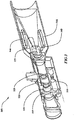
- FIG 1 is an illustration of an embodiment of the firearm or air gun sighting scope 100. It appears very similar to other scopes but has very different functionality.
- An elevation knob 140 has an electronic button 150.
- a windage knob 120 also has an electronic button 130.
- an optical zoom adjustment is shown as 110.
- FIG. 2 is a schematic representation of the sub-systems with the two major parts shown as the advanced intelligent firearm or air gun scope (Scope) in the top half of the representation that provides all of the functionality of attitude tracking, and the Trigger Monitoring and Control (TMC), represented in the bottom half (Ballistic Device) that provides firing synchronization.
- Scope advanced intelligent firearm or air gun scope
- TMC Trigger Monitoring and Control
- the proposed scope has three major components - a muzzle-tracking module (MTM) 220, a range finding module 240 and an optical display system 260.
- the muzzle-tracking module contains an array of gyroscopes and an image sensor for muzzle position tracking and an inclinometer to determine shot angle relative to gravity. All of these feed into a core microprocessor 280 with embedded software that provides the intelligence for the system. All of the microprocessor capability can be supplied with one central microprocessor as shown or that capability could be split between the various modules.
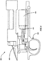
- Figure 3 is a rendering of the internals of the firearm or air gun sighting scope.
- Range finding module 240 uses a "time of flight" laser range finding approach.
- An off axis infrared laser 350 generates light that is reflected using beam splitters 345 into the scope optical path toward the target.
- Laser light is emitted in timed pulses that illuminate the target.
- the returning reflection from the target is detected by an avalanche photodiode receiver 340 and the time delay is measured to with 1 nanosecond. This time of flight is used to determine the distance to the target.
- the scope also contains an optical display system 260. It is built around a zoom power scope with zoom lenses 320, 325 that typically give a 3X-12X power range but is not limited to that.
- the sighting scope also includes a display beam splitter 335, and an image sensor 310. Power is supplied by an internal battery 335.
- the invention anticipates that the scope can be a video (camera) scope or a natural light scope.
- the optical system projects the reticle, range and configuration screens onto a display 345 in the field of view.
- One aspect of the optical display system is the capability of the shooter to initially position the horizontal and vertical reticles (crosshair) on a potential target and press the shot control button 130 on the windage knob 120 (see Figure 1 ) to illuminate a colored dot or designation-dot that represents the desired designation point on the target. This is used in shot simulation, muzzle tracking, and trigger synchronization to be described later.
- Trigger control and monitoring 290 is separate from the scope, as shown in Figure 2 .
- the proposed scope can mount on any firearm or air gun device, including various rifles and bows.
- the firearm or air gun device must be specially modified with Trigger Monitor and Control (TMC) capability.
- TMC Trigger Monitor and Control
- TMC capability in shown in Figure 4 as system 400 which includes 1) a solenoid 440 with proximity switch 430 that functions to restrict firing when off target, and 2) internal wiring and connector to connect the solenoid to the scope.
- the TMC includes a two state trigger 410 and shot control switch 410.
- the mechanism increases the trigger pull force when the solenoid is activated from normal trigger pull force of approximately 2 lbs to a restricting force of about 8 lbs. If the shooter applies more than 8 lbs of force to the trigger, he may fire in spite of the solenoid's restricting force.
- a second embodiment of the TMC capability, shown in Figure 5 as system 500 is a nitinol wire variable force trigger, which consists of 1) a nitinol wire retractor 510, 2) a wedge pin 530, 3) a cantilever spring 520, and 4) a trigger spring 535.
- This mechanism increases the trigger pull force when the wedge pin is moved between the cantilever spring and trigger sear.
- the trigger pull force of approximately 2 lbs inflates to a restricting force of about 8 lbs. If the shooter applies more than 8 lbs of force to the trigger, he may fire in spite of the spring's restricting force.
- a third embodiment of the TMC (not shown) consists of an electric trigger system consisting of a safety switch, a 2 lbs switch and an 8 lbs switch on the trigger, an electrically activated primer for discharging the firearm, a bolt with an internal electrical contact for electrical connection to the primer and an electronic activation circuit for activation of the primer.
- This circuit performs the same functions typical of a trigger design, including monitoring the safety switch and trigger switches.
- a trigger pull of 8 lbs or more will fire the gun, and a trigger pull of 2 lbs or more but less than 8 lbs will fire the gun only if the gun is aligned with the designation point.
- the scope has three primary capabilities: a direction designation method such as a Shot Simulator, a muzzle tracking method such as the Muzzle Tracking Module to measure angular deviations from the designated direction, and a synchronized firing method such as the Trigger Monitor and Control mechanism. Each is described below.
- Shot Simulator The proposed scope allows the shooter to quickly and automatically simulate a shot before firing.
- a colored dot (designation-dot) appears in the field-of-view where the horizontal and vertical reticles cross (cross-hair).
- This designation dot or designation point represents the muzzle position at designation time and simulates the point of impact should the shooter pull the trigger. If the shooter is satisfied with the impact point as marked by the designation-dot, he pulls the trigger while endeavoring to keep the cross-hair on the designation-dot.
- the shooter If the shooter is not satisfied with the designated impact point, he attempts to realign the cross hair with his intended impact point, and presses the shot control button again, at which time the designation-dot reappears. The shooter can repeat the simulation multiple times until he is satisfied with the impact point indicated by the designation-dot.
- Muzzle Tracking As natural shooter jitter occurs, the cross-hair will move off the simulated point of impact but the designation-dot or designation point will stay fixed with the field of view. This is done by continually monitoring and processing the field-of-view image. Movement in the image represents the rate and direction of muzzle movement. The muzzle-tracking module continuously tracks angular deviations of the muzzle from the angular position designation point. Using kinematic equations, the microprocessor can then predict when the muzzle will re-intersect the designation point. These kinematic equations take into account angle and direction of muzzle movement and the time it takes for the firing-pin to strike and launch the bullet.
- Shot Synchronizer If the Shot Synchronizer is in use, the trigger pull will be resisted or inflated while the angular deviations of the muzzle from the angular position designation point are above an acceptable level, but the trigger resistance will relax or deflate when the cross-hairs approach the designation-dot and the deviation of the muzzle from the angular position designation point are below an acceptable level. This enables firing of the firearm or air gun when the angular deviation of the firearm or air gun muzzle from the angular position designation point is at an acceptable level and prevents or impedes firing when the angular deviation of the firearm or air gun muzzle from the angular position designation point is above the acceptable level. If the Shot Synchronizer is not in use, the trigger will release when the normal trigger pull-force has been exceeded.
- a typical shooter will introduce human jitter and trigger jerk somewhere between 2 and 15 minutes of angle (MOA). At 500 yards a shooter could miss the target by up to 75 inches or more.
- the Shot Synchronizer limits the impact of human jitter and trigger jerk to 0.8 MOA which is about 4 inches at 500 yards. This type of accuracy is attainable even if the shooter is firing "off-hand" without a gun rest.
- the Shot Synchronizer works in conjunction with the Shot Simulator.
- an actuator in the trigger inflates the trigger pull force (to approximately 8 lbs.) to restrict firing.
- the actuator releases and normal trigger pressure (2 to 3) pounds is overridden by the shooter and the shot is fired.
- the firearm or air guns scope has an embedded laser range finder.
- a laser diode generates a beam of light that is projected out through the scope through a beam splitter.
- the range finder can operate to 800 yards with an accuracy of +/-1.5 yard.
- the range finder can be activated in two ways. With rifles that include the trigger control and monitoring system 290, the range finder can be activated by pressing the shot control button. For non-trigger control and monitoring system firearm or air gun devices, the range finder is activated by one of the buttons on the firearm or air guns scope.
- the range finder also has a weather station that records wind speed, humidity, and air pressure.
- the reticle on the firearm or air guns scope is electronically positioned in the field-of-view of the scope.
- the positions of the horizontal and vertical axis of the reticle are automatically repositioned in the field-of-view based on target range, bullet ballistics, wind and muzzle incline/decline.
- the new cross-hair, based on the repositioned reticles, becomes the shooters target alignment point.
- the reticle is typically not displayed when the gun is not in use. When the gun is moved to roughly a horizontal position the reticle appears.
- the proposed scope includes a plurality of buttons and selection knobs ( Figure 1 ) that allow the user to configure, manage, and operate the scope. These buttons and knobs are the interface for the user. Some of the variables that can be input through these controls are at least: Power On/Off, shot control button, wind direction and speed, gun type, ammunition type, reticle type, and configuration of other user preferences.
- the windage knob and button on the User Control Interface allow the selection of Configuration Mode.
- This mode displays a menu which is scrolled by twisting the windage knob and selected by pressing the windage knob's button.
- Two additional features are selectable from this menu: - Single-Shot Automatic Alignment Mode and Ammo Select.
- the proposed scope's automatic alignment capability is a significant innovation. Without this capability, a typical shooter may take a dozen or more shots and up to an hour's time aligning the scope with the muzzle. This manual process is often unreliable because of shooter jitter and trigger jerk.
- the proposed scope eliminates the need for mechanical alignment turrets, eliminates the need to know the range of the alignment target and eliminates error due to jitter and jerk.
- the shooter aligns the cross hair on the center of the target and presses the shot control button. If the designation-dot is on the center of the target, the shooter completes the shot by increasing trigger pressure. The shooter then lines up on the target center, presses the shot control button, moves the cross-hairs to where the round impacted the target and again presses the shot control button. The cross hairs then adjust automatically completing alignment.
- Update Mode In this mode the proposed scope is connected to a laptop via a universal serial bus (USB) cable. In Update Mode, the scope can download new software, new ammunition information, and new rifle types.
- USB universal serial bus
- the proposed scope can operate in Standard mode or Advanced mode. Selection of the mode is made by a switch on the side of the scope.
- Standard mode the reticles are displayed in a default location and only updated from that location if the elevation or windage knobs are moved. This mode emulates the features and actions typically found in a traditional riflescope and therefore does not synchronize the trigger or affect it in any way.
- Advanced mode all the advanced features of the scope are enabled including the Shot Simulator, Muzzle Tracking, Shot Synchronization, Automatic Ballistics Crosshair, and the other advanced features.
- Directed Point When the user points the rifle at a target (DP) the proposed scope detects when the gun is in a steady shooting position by monitoring the inclinometer and gyroscopes. When a Directed Point is detected, the scope automatically powers up and displays the default reticle.
- Reset Action A double press of the Shot Control Sutton will generally abort the current action and reset the scope back to showing its default reticle.
- Step 1 - Ranging The ballistics scope built-in range finder can range targets up to 800 yards away. In hunting, once the animal is identified, the shooter will find the animal in the scope. He/she will place the cross hair on the animal and press (SCP) the shot control button. The range finder will automatically find the range. The user releases (SCR) the shot control and the range is locked in. The range is displayed in the scope field of view and the range information is used by the scope to set the ballistics reticles. If the shooter ranged on the wrong target or wants to re-start the shooting process for any reason he does a rapid double press. This rapid double press is called the "Reset Action" (SOC). The scope also reverts to the pre-shot state when the rifle is roughly vertical as detected by the inclinometer and gyroscopes.
- SCP cross hair on the animal and press
- SCR shot control button
- the range finder will automatically find the range.
- Step 2 Taking A Simulated Shot -
- the shooter moves the ballistics-adjusted crosshair to the desired designation point on the target and presses (SCP) the shot control button.
- a colored "designation-dot" appears in the field of view. This dot can be any color but is most likely to be set by the user for red or green. This dot is a simulation of where the bullet will impact the target. If the shooter is not satisfied with the simulated shot location he attempts once again to place the colored designation-dot on the target's desired target zone and presses the shot control button again, simulating another shot.
- the shooter can repeat (SCP) Step 2 multiple times if necessary. Once simulated, muzzle tracking is active and the trigger pressure is inflated. At any time, the shooter can re-start the shot by executing the Reset Action (SOC).
- SOC Reset Action
- Step 3 Synchronized Firing - Satisfied with the location of the impact point represented by the designation-dot, the shooter increases trigger pressure to the normal trigger pressure of the rifle (2 to 3 pounds) but the inflated trigger pressure does not allow a shot.
- the cross-hair may move off the impact point, but the designation-dot will appear to remain stable on the impact point (as long as the field of view is stationary).
- the scope will track muzzle movement and will restrict the rifle from firing until the crosshair is realigned with the dot at which time the trigger solenoid is released and the bullet is fired.
- the shooter can re-start the shot by executing the Reset Action (SOC). Once the rifle fires (Fire Detected) the system returns to Range Lock to for another possible shot.
- SOC Reset Action
- Figure 6 also exhibits the other possible system states of configuration, update, and ammo select.
Description
- This description relates to ballistic muzzle tracking and related devices, and especially to telescopic ballistic sights to achieve medium and long-range accuracy in the presence of normal human tremor.
- Shooting a firearm or air gun device accurately requires that many variables be taken into consideration - human steadiness or lack thereof, angle of shot (uphill or downhill), distance, bullet ballistic information (velocity, sensitivity to wind), and wind speed all affect the accuracy of a given shot. The problem is that there is no way for most shooters to integrate or eliminate all of these variables and make an accurate shot. This is particularly true for shots beyond 200 yards and shots at smaller targets. As a result, shots between 200 yards and 500 yards are rarely completed successfully. A typical shooter will introduce human jitter and trigger jerk somewhere between 2 and 15 minutes of angle (MOA). At 500 yards, a shooter could miss the target by up to 75 inches or more.
- The issue of human steadiness is a critical one and has been addressed in the prior art. Most solutions tend to be approaches that involve the active stabilization of the rifle. An example is
EP0898144 B1 in which, during a tracking mode, undesired motion is sensed by position sensors and the information is fed to inertial rate sensors make the barrel relatively immune to movement of the stock to facilitate the barrel remaining sighted on the tracked target.U.S. Patent 7,055,276 describes a damper system for reducing vibrations during and after firing, that involves adding damper weights to the firearm. Similarly, PCT applicationWO8102925 A1 - All of these approaches might be termed as active stabilization of the rifle. They may help reduce tremor but can involve specially designed rifles or significantly cumbersome additions to known rifles.
-
US 2006/005447 A1 relates to a digital processor aiming and firing system generating a trigger signal with electronic timing exactness. To achieve this, a view down the barrel sight is captured by a digital video camera and analyzed on a frame-by-frame basis by an electronic processor equipped with image identification software. Motion detectors attached to the weapon are used to interpolate the barrel position between frames. A motion history of the barrel position relative to the target is calculated and an extrapolation of the future position is made. -
US 7,404,268 B1 describes a precision targeting system for a firearm that has an image capturing scope, a processor, and an actuator. In one embodiment, a user indicates when he wants to lock onto the target, and then readjust his aim after receiving feedback from the system. In another embodiment, the system automatically locks onto the target. After lock on, the system compares successive images, and determines if the target has moved in the firearm sight. If movement has occurred, the system calculates the degree of the movement, and sends appropriate signals to an actuator which corrects the aim of the firearm. -
US 2004/099134 A1 relates to a system for monitoring use of a weapon. The system includes a monitoring station and at least one weapon in which the weapon fires a projectile. The weapon includes a tracking device, in which the tracking device receives navigational data, and a transceiver. The transceiver transmits at least the navigational data to the monitoring station. -
US 6,843,014 B1 describes a shape memory alloy serving to actuate or inhibit the function of a semi-automatic pistol in response to an identification signal produced by an identifier. The identifier operates to either detect the present or absence of an authorized user thereby enabling or disabling the function of the weapon. -
US 6,886,287 B1 relates to a rifle scope system allowing adjustment of the scope while a shooter maintains the shooting posture and the scope sight picture. The scope system comprises an adjustment system comprising an electromechanical mechanism that responds to a signal from a remote controller manipulated by the shooter without having to significantly disturb the shooting posture. The adjustment system allows the shooter to adjust the scope's point of aim to coincide with a bullet's point of impact at a target. -
US 6,871,439 B1 describes a weapon for accurately launching a projectile of a firearm toward a target and no other point of strike, comprising an electrically-actuated firearm with axially-stacked ammunition loads, a target sensor unit which generates a target sensor signal at such times as the projected bullet's point of strike and the projected target position coincide; a fire controller which generates a firing signal when both a trigger signal and a target sensor signal are present; and a sequence controller actuated by the firing signal to ignite one or more of the axially stacked ammunition loads to cause the projectile to strike the projected location of a target. - There is a need for a different approach, one that can be applied to a wide variety of firearm or air gun devices, and that does not require cumbersome additions to the firearm or air gun devices. This is achieved in this description by using not active rifle stabilization but attitude tracking coupled with firing synchronization.
- The above identified needs are met by a method as specified in independent claim 1.
- The above identified needs are also met by a system as specified by independent claim 7.
- In order that the invention can be more clearly ascertained examples of preferred embodiments will now be described with reference to the accompanying drawings wherein:
-
Figure 1 is a rendering of an embodiment of the firearm or air gun sighting scope. -
Figure 2 is a schematic of functional subsystems of the firearm or air gun sighting scope system. -
Figure 3 is a cutaway view of an embodiment of the firearm or air gun sighting scope. -
Figure 4 is a rendering of a trigger control embodiment. -
Figure 5 is a rendering of another trigger control embodiment. -
Figure 6 is a schematic of the states of the system. -
Figure 1 is an illustration of an embodiment of the firearm or airgun sighting scope 100. It appears very similar to other scopes but has very different functionality. Anelevation knob 140 has anelectronic button 150. Awindage knob 120 also has anelectronic button 130. As in other scopes an optical zoom adjustment is shown as 110. - The complete firearm or air gun sighting scope system can be broken into two parts: a scope and a ballistic device.
Figure 2 is a schematic representation of the sub-systems with the two major parts shown as the advanced intelligent firearm or air gun scope (Scope) in the top half of the representation that provides all of the functionality of attitude tracking, and the Trigger Monitoring and Control (TMC), represented in the bottom half (Ballistic Device) that provides firing synchronization. - The proposed scope has three major components - a muzzle-tracking module (MTM) 220, a
range finding module 240 and anoptical display system 260. The muzzle-tracking module contains an array of gyroscopes and an image sensor for muzzle position tracking and an inclinometer to determine shot angle relative to gravity. All of these feed into acore microprocessor 280 with embedded software that provides the intelligence for the system. All of the microprocessor capability can be supplied with one central microprocessor as shown or that capability could be split between the various modules. -
Figure 3 is a rendering of the internals of the firearm or air gun sighting scope.Range finding module 240 uses a "time of flight" laser range finding approach. An off axisinfrared laser 350 generates light that is reflected usingbeam splitters 345 into the scope optical path toward the target. Laser light is emitted in timed pulses that illuminate the target. The returning reflection from the target is detected by anavalanche photodiode receiver 340 and the time delay is measured to with 1 nanosecond. This time of flight is used to determine the distance to the target. - The scope also contains an
optical display system 260. It is built around a zoom power scope withzoom lenses display beam splitter 335, and animage sensor 310. Power is supplied by aninternal battery 335. The invention anticipates that the scope can be a video (camera) scope or a natural light scope. The optical system projects the reticle, range and configuration screens onto adisplay 345 in the field of view. One aspect of the optical display system is the capability of the shooter to initially position the horizontal and vertical reticles (crosshair) on a potential target and press theshot control button 130 on the windage knob 120 (seeFigure 1 ) to illuminate a colored dot or designation-dot that represents the desired designation point on the target. This is used in shot simulation, muzzle tracking, and trigger synchronization to be described later. - Trigger control and
monitoring 290 is separate from the scope, as shown inFigure 2 . The proposed scope can mount on any firearm or air gun device, including various rifles and bows. However, to utilize the scope shot stabilization capability the firearm or air gun device must be specially modified with Trigger Monitor and Control (TMC) capability. - One embodiment of the TMC capability in shown in
Figure 4 assystem 400 which includes 1) asolenoid 440 withproximity switch 430 that functions to restrict firing when off target, and 2) internal wiring and connector to connect the solenoid to the scope. The TMC includes a twostate trigger 410 and shotcontrol switch 410. The mechanism increases the trigger pull force when the solenoid is activated from normal trigger pull force of approximately 2 lbs to a restricting force of about 8 lbs. If the shooter applies more than 8 lbs of force to the trigger, he may fire in spite of the solenoid's restricting force. - A second embodiment of the TMC capability, shown in
Figure 5 assystem 500 is a nitinol wire variable force trigger, which consists of 1) anitinol wire retractor 510, 2) awedge pin 530, 3) acantilever spring 520, and 4) atrigger spring 535. This mechanism increases the trigger pull force when the wedge pin is moved between the cantilever spring and trigger sear. When the wedge pin is in place, the trigger pull force of approximately 2 lbs inflates to a restricting force of about 8 lbs. If the shooter applies more than 8 lbs of force to the trigger, he may fire in spite of the spring's restricting force. - A third embodiment of the TMC (not shown) consists of an electric trigger system consisting of a safety switch, a 2 lbs switch and an 8 lbs switch on the trigger, an electrically activated primer for discharging the firearm, a bolt with an internal electrical contact for electrical connection to the primer and an electronic activation circuit for activation of the primer. This circuit performs the same functions typical of a trigger design, including monitoring the safety switch and trigger switches. A trigger pull of 8 lbs or more will fire the gun, and a trigger pull of 2 lbs or more but less than 8 lbs will fire the gun only if the gun is aligned with the designation point.
- The scope has three primary capabilities: a direction designation method such as a Shot Simulator, a muzzle tracking method such as the Muzzle Tracking Module to measure angular deviations from the designated direction, and a synchronized firing method such as the Trigger Monitor and Control mechanism. Each is described below.
- Shot Simulator - The proposed scope allows the shooter to quickly and automatically simulate a shot before firing. When the shooter aligns the reticle on a desired target and presses the shot control button on the windage knob, a colored dot (designation-dot) appears in the field-of-view where the horizontal and vertical reticles cross (cross-hair). This designation dot or designation point represents the muzzle position at designation time and simulates the point of impact should the shooter pull the trigger. If the shooter is satisfied with the impact point as marked by the designation-dot, he pulls the trigger while endeavoring to keep the cross-hair on the designation-dot.
- If the shooter is not satisfied with the designated impact point, he attempts to realign the cross hair with his intended impact point, and presses the shot control button again, at which time the designation-dot reappears. The shooter can repeat the simulation multiple times until he is satisfied with the impact point indicated by the designation-dot.
- Muzzle Tracking - As natural shooter jitter occurs, the cross-hair will move off the simulated point of impact but the designation-dot or designation point will stay fixed with the field of view. This is done by continually monitoring and processing the field-of-view image. Movement in the image represents the rate and direction of muzzle movement. The muzzle-tracking module continuously tracks angular deviations of the muzzle from the angular position designation point. Using kinematic equations, the microprocessor can then predict when the muzzle will re-intersect the designation point. These kinematic equations take into account angle and direction of muzzle movement and the time it takes for the firing-pin to strike and launch the bullet.
- Shot Synchronizer - If the Shot Synchronizer is in use, the trigger pull will be resisted or inflated while the angular deviations of the muzzle from the angular position designation point are above an acceptable level, but the trigger resistance will relax or deflate when the cross-hairs approach the designation-dot and the deviation of the muzzle from the angular position designation point are below an acceptable level. This enables firing of the firearm or air gun when the angular deviation of the firearm or air gun muzzle from the angular position designation point is at an acceptable level and prevents or impedes firing when the angular deviation of the firearm or air gun muzzle from the angular position designation point is above the acceptable level. If the Shot Synchronizer is not in use, the trigger will release when the normal trigger pull-force has been exceeded.
- A typical shooter will introduce human jitter and trigger jerk somewhere between 2 and 15 minutes of angle (MOA). At 500 yards a shooter could miss the target by up to 75 inches or more. The Shot Synchronizer limits the impact of human jitter and trigger jerk to 0.8 MOA which is about 4 inches at 500 yards. This type of accuracy is attainable even if the shooter is firing "off-hand" without a gun rest. The Shot Synchronizer works in conjunction with the Shot Simulator. When the Shot Synchronizer is in use, an actuator in the trigger inflates the trigger pull force (to approximately 8 lbs.) to restrict firing. When the cross-hair intersects the designation-dot the actuator releases and normal trigger pressure (2 to 3) pounds is overridden by the shooter and the shot is fired.
- In addition to these primary functions the proposed scope has the following additional embodiments:
- Built-in Range-Finder - The firearm or air guns scope has an embedded laser range finder. A laser diode generates a beam of light that is projected out through the scope through a beam splitter. The range finder can operate to 800 yards with an accuracy of +/-1.5 yard. The range finder can be activated in two ways. With rifles that include the trigger control and
monitoring system 290, the range finder can be activated by pressing the shot control button. For non-trigger control and monitoring system firearm or air gun devices, the range finder is activated by one of the buttons on the firearm or air guns scope. The range finder also has a weather station that records wind speed, humidity, and air pressure. - Automatic Ballistics Crosshair - Prior to shot simulation, the reticle on the firearm or air guns scope is electronically positioned in the field-of-view of the scope. After ranging the shot the positions of the horizontal and vertical axis of the reticle are automatically repositioned in the field-of-view based on target range, bullet ballistics, wind and muzzle incline/decline. The new cross-hair, based on the repositioned reticles, becomes the shooters target alignment point. The reticle is typically not displayed when the gun is not in use. When the gun is moved to roughly a horizontal position the reticle appears.
- User Control Interface - The proposed scope includes a plurality of buttons and selection knobs (
Figure 1 ) that allow the user to configure, manage, and operate the scope. These buttons and knobs are the interface for the user. Some of the variables that can be input through these controls are at least: Power On/Off, shot control button, wind direction and speed, gun type, ammunition type, reticle type, and configuration of other user preferences. - The windage knob and button on the User Control Interface allow the selection of Configuration Mode. This mode displays a menu which is scrolled by twisting the windage knob and selected by pressing the windage knob's button. Two additional features are selectable from this menu: - Single-Shot Automatic Alignment Mode and Ammo Select.
- Single-Shot Automatic Alignment - The proposed scope's automatic alignment capability is a significant innovation. Without this capability, a typical shooter may take a dozen or more shots and up to an hour's time aligning the scope with the muzzle. This manual process is often unreliable because of shooter jitter and trigger jerk. The proposed scope eliminates the need for mechanical alignment turrets, eliminates the need to know the range of the alignment target and eliminates error due to jitter and jerk. When in auto alignment mode, the shooter aligns the cross hair on the center of the target and presses the shot control button. If the designation-dot is on the center of the target, the shooter completes the shot by increasing trigger pressure. The shooter then lines up on the target center, presses the shot control button, moves the cross-hairs to where the round impacted the target and again presses the shot control button. The cross hairs then adjust automatically completing alignment.
- Update Mode - In this mode the proposed scope is connected to a laptop via a universal serial bus (USB) cable. In Update Mode, the scope can download new software, new ammunition information, and new rifle types.
- The proposed scope can operate in Standard mode or Advanced mode. Selection of the mode is made by a switch on the side of the scope. In Standard mode, the reticles are displayed in a default location and only updated from that location if the elevation or windage knobs are moved. This mode emulates the features and actions typically found in a traditional riflescope and therefore does not synchronize the trigger or affect it in any way. In Advanced mode, all the advanced features of the scope are enabled including the Shot Simulator, Muzzle Tracking, Shot Synchronization, Automatic Ballistics Crosshair, and the other advanced features.
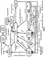
- Operation in Advanced mode can be understood by reference to
Figure 6 , beginning in the Power Off mode. The power up to Advanced mode is indicated by the Power Up command or PU, which is a power switch on the side of the scope. This puts the scope in standby mode. Each primary capability is then activated either through a "Directed Point," or a press of the shot control button: - Directed Point - When the user points the rifle at a target (DP) the proposed scope detects when the gun is in a steady shooting position by monitoring the inclinometer and gyroscopes. When a Directed Point is detected, the scope automatically powers up and displays the default reticle.
- Reset Action - A double press of the Shot Control Sutton will generally abort the current action and reset the scope back to showing its default reticle.
- Step 1 - Ranging - The ballistics scope built-in range finder can range targets up to 800 yards away. In hunting, once the animal is identified, the shooter will find the animal in the scope. He/she will place the cross hair on the animal and press (SCP) the shot control button. The range finder will automatically find the range. The user releases (SCR) the shot control and the range is locked in. The range is displayed in the scope field of view and the range information is used by the scope to set the ballistics reticles. If the shooter ranged on the wrong target or wants to re-start the shooting process for any reason he does a rapid double press. This rapid double press is called the "Reset Action" (SOC). The scope also reverts to the pre-shot state when the rifle is roughly vertical as detected by the inclinometer and gyroscopes.
- Step 2 - Taking A Simulated Shot - The shooter moves the ballistics-adjusted crosshair to the desired designation point on the target and presses (SCP) the shot control button. A colored "designation-dot" appears in the field of view. This dot can be any color but is most likely to be set by the user for red or green. This dot is a simulation of where the bullet will impact the target. If the shooter is not satisfied with the simulated shot location he attempts once again to place the colored designation-dot on the target's desired target zone and presses the shot control button again, simulating another shot. The shooter can repeat (SCP)
Step 2 multiple times if necessary. Once simulated, muzzle tracking is active and the trigger pressure is inflated. At any time, the shooter can re-start the shot by executing the Reset Action (SOC). - Step 3 - Synchronized Firing - Satisfied with the location of the impact point represented by the designation-dot, the shooter increases trigger pressure to the normal trigger pressure of the rifle (2 to 3 pounds) but the inflated trigger pressure does not allow a shot. As normal shooter jitter occurs, the cross-hair may move off the impact point, but the designation-dot will appear to remain stable on the impact point (as long as the field of view is stationary). The scope will track muzzle movement and will restrict the rifle from firing until the crosshair is realigned with the dot at which time the trigger solenoid is released and the bullet is fired. At any time the shooter can re-start the shot by executing the Reset Action (SOC). Once the rifle fires (Fire Detected) the system returns to Range Lock to for another possible shot.
-
Figure 6 also exhibits the other possible system states of configuration, update, and ammo select. - All of the methods disclosed and claimed herein can be executed without undue experimentation in light of the present disclosure.
Claims (10)
- A method performed with a scope (100) coupled to a firearm, the method comprising the following steps:- displaying a reticle within a view area of the scope (100), whereby the reticle consists of a horizontal and vertical reticle and whereby the position where the horizontal and vertical reticles cross represents the muzzle position;- placing the reticle on a target and initiating a range finding action via a laser-based range finding module (240) to determine a range associated with the target;- automatically repositioning the horizontal and vertical axis of the reticle in the view area based on the target range, bullet ballistics, wind and incline/decline of a muzzle of the firearm to provide an automatic ballistics reticle,- moving the reticle to a point on the target and defining a colored designation point which remains fixed within a view area of the scope (100);- activating a muzzle tracking module (220) to continuously track angular deviation of the muzzle position from the designation point,- determining an angular deviation of the muzzle position of the firearm from the designation point; and- initiating firing of the firearm when the angular deviation is below a threshold level.
- The method of claim 1, wherein initiating the firing of the firearm comprises receiving a signal (SCP) corresponding to a user-selection of a shot control element when the horizontal and vertical axis of the reticle are aligned with the designation point.
- The method of claim 1, wherein the range finding module (240) further comprises a weather station that records wind speed, humidity, and air pressure.
- The method of claim 1, further comprising:increasing a resistance of a variable force trigger (400) to resist a trigger pull while the
angular deviation of the muzzle from the designation point exceed a threshold level; andreducing a trigger resistance of the variable force trigger when the angular deviation of the muzzle from the designation point falls below the threshold. - The method of claim 4, wherein the variable force trigger includes at least one of a solenoid and a nitinol wire variable force trigger (400, 500).
- The method of claim 4, wherein the variable force trigger comprises an electronic trigger switch, and wherein increasing the resistance comprises:activating the electronic trigger switch when the cross-hairs approach the designation point and the angular deviation of the muzzle is below the threshold level.
- A system comprising:a firearm having a muzzle,a scope (100) coupled to the firearm, said scope having a view area and including:means (260) to computationally generate and to automatically reposition an automatic ballistics reticle in a field of view of the scope based on target range, bullet ballistics, wind, and muzzle incline/decline, whereby the reticle consists of a horizontal and vertical reticle and whereby the position where the horizontal and vertical reticles cross represents the muzzle position;a laser range finder (240);at least one user-selectable control element (130) accessible by a user configured to assign a colored designation point to a target in the view area, whereby the designation point represents the muzzle position at designation time and remains fixed within the view area;a muzzle tracking module (220) configured to track an angular deviation of the muzzle of the firearm from the designation point; anda synchronized trigger mechanism (290) coupled to the scope (100) and configured to enable firing of the firearm when the angular deviation of the muzzle from the user-defined designation point is below a threshold level and to impede firing of the firearm when the angular deviation of the muzzle from the user-defined designation point is above the threshold level.
- The system of claim 7, wherein said muzzle tracking module (220) further comprises:an image sensor (310);an inclinometer; andone or more gyroscopes.
- The system of claim 7, wherein the synchronized trigger mechanism (290) comprises at least one of a solenoid and a nitinol wire variable force trigger (400, 500) configured to prevent firing of the firearm in response to a control signal indicating when the angular deviation of the muzzle from the user-defined designation point is above the threshold level.
- The system of claim 7, wherein the synchronized trigger mechanism (290) includes an electric trigger system comprising:a safety switch to prevent firing when the angular deviation of the muzzle from the user-defined designation point is above the threshold level;an electrically activated primer;a bolt with an internal electrical contact for electrical connection to the electrically activated primer; andan electronic activation circuit for activation of the electrically activated primer.
Applications Claiming Priority (2)
| Application Number | Priority Date | Filing Date | Title |
|---|---|---|---|
| US33820310P | 2010-02-16 | 2010-02-16 | |
| PCT/US2011/000281 WO2011102894A2 (en) | 2010-02-16 | 2011-02-16 | Advanced firearm or air gun scope |
Publications (3)
| Publication Number | Publication Date |
|---|---|
| EP2536995A2 EP2536995A2 (en) | 2012-12-26 |
| EP2536995A4 EP2536995A4 (en) | 2014-11-26 |
| EP2536995B1 true EP2536995B1 (en) | 2017-10-04 |
Family
ID=44483519
Family Applications (1)
| Application Number | Title | Priority Date | Filing Date |
|---|---|---|---|
| EP11744995.9A Active EP2536995B1 (en) | 2010-02-16 | 2011-02-16 | Method and system of controlling a firearm |
Country Status (3)
| Country | Link |
|---|---|
| US (2) | US9110295B2 (en) |
| EP (1) | EP2536995B1 (en) |
| WO (1) | WO2011102894A2 (en) |
Cited By (2)
| Publication number | Priority date | Publication date | Assignee | Title |
|---|---|---|---|---|
| US10907934B2 (en) | 2017-10-11 | 2021-02-02 | Sig Sauer, Inc. | Ballistic aiming system with digital reticle |
| US11454473B2 (en) | 2020-01-17 | 2022-09-27 | Sig Sauer, Inc. | Telescopic sight having ballistic group storage |
Families Citing this family (22)
| Publication number | Priority date | Publication date | Assignee | Title |
|---|---|---|---|---|
| US9110295B2 (en) * | 2010-02-16 | 2015-08-18 | Trackingpoint, Inc. | System and method of controlling discharge of a firearm |
| GB201010207D0 (en) * | 2010-06-18 | 2010-07-21 | Craven David | a viewing apparatus |
| US8807430B2 (en) | 2012-03-05 | 2014-08-19 | James Allen Millett | Dscope aiming device |
| US8881981B2 (en) | 2012-03-05 | 2014-11-11 | James A. Millett | Digital targeting scope apparatus |
| US10782097B2 (en) * | 2012-04-11 | 2020-09-22 | Christopher J. Hall | Automated fire control device |
| US20140182187A1 (en) * | 2012-12-31 | 2014-07-03 | Trackingpoint, Inc. | Software-Extensible Gun Scope and Method |
| US20140184476A1 (en) * | 2012-12-31 | 2014-07-03 | Trackingpoint, Inc. | Heads Up Display for a Gun Scope of a Small Arms Firearm |
| AT513599B1 (en) * | 2013-01-08 | 2014-06-15 | Swarovski Optik Kg | sight |
| US9222754B2 (en) * | 2013-06-07 | 2015-12-29 | Trackingpoint, Inc. | Precision guided firearm with hybrid sensor fire control |
| US9074846B2 (en) * | 2013-07-16 | 2015-07-07 | MAG Security Consultants, Inc. | Scope cap |
| US20150211828A1 (en) * | 2014-01-28 | 2015-07-30 | Trackingpoint, Inc. | Automatic Target Acquisition for a Firearm |
| KR101932544B1 (en) * | 2014-04-16 | 2018-12-27 | 한화지상방산 주식회사 | Remote-weapon apparatus and control method thereof |
| IL232828A (en) | 2014-05-27 | 2015-06-30 | Israel Weapon Ind I W I Ltd | Apparatus and method for improving hit probability of a firearm |
| US9541573B2 (en) * | 2014-08-27 | 2017-01-10 | Bae Systems Information And Electronic Systems Integration Inc. | Movement compensation of firearms |
| AU2016229070A1 (en) * | 2015-03-09 | 2017-08-31 | Cubic Corporation | Integrated wind laser rangefinder receiver |
| US10969186B2 (en) | 2017-03-08 | 2021-04-06 | Strum, Ruger & Company, Inc. | Fast action shock invariant magnetic actuator for firearms |
| US10240881B1 (en) | 2017-03-08 | 2019-03-26 | Louis M. Galie | Fast action shock invariant magnetic actuator for firearms |
| US11353278B2 (en) * | 2018-04-30 | 2022-06-07 | Hydra Concepts | Systems and methods for firearm aim-stabilization |
| TWM572976U (en) * | 2018-09-06 | 2019-01-11 | 龍鵬實業有限公司 | Sight |
| CN109141891A (en) * | 2018-09-10 | 2019-01-04 | 南京航空航天大学 | A kind of sighting device damaging light-gas gun for simulating hard object |
| USD901615S1 (en) * | 2019-05-09 | 2020-11-10 | Aimlock Inc. | Trigger and safety mechanism |
| US20210364256A1 (en) * | 2020-04-21 | 2021-11-25 | Axon Enterprise, Inc. | Motion-based operation for a conducted electrical weapon |
Family Cites Families (34)
| Publication number | Priority date | Publication date | Assignee | Title |
|---|---|---|---|---|
| US953279A (en) * | 1910-02-02 | 1910-03-29 | Robert A Moore | Trigger-controller. |
| GB1605027A (en) * | 1977-04-07 | 1981-12-16 | Emi Ltd | Aiming arrangements |
| EP0049275A1 (en) | 1980-04-01 | 1982-04-14 | THEODORE, Paris | Firearm stabilizing device |
| USH538H (en) * | 1984-12-20 | 1988-11-01 | The United States Of America As Represented By The Secretary Of The Army | Weapon firing inhibitor method and apparatus |
| US4787291A (en) | 1986-10-02 | 1988-11-29 | Hughes Aircraft Company | Gun fire control system |
| TR27014A (en) * | 1987-05-15 | 1994-09-15 | Contraves Ag | The method of orientation for a fire management device and the fire management device for performing this method. |
| US5280744A (en) * | 1992-01-27 | 1994-01-25 | Alliedsignal Inc. | Method for aiming towed field artillery pieces |
| US5456157A (en) * | 1992-12-02 | 1995-10-10 | Computing Devices Canada Ltd. | Weapon aiming system |
| US5379676A (en) * | 1993-04-05 | 1995-01-10 | Contraves Usa | Fire control system |
| US6237271B1 (en) * | 1996-07-23 | 2001-05-29 | Colt's Manufacturing Company, Inc. | Firearm with safety system having a communication package |
| US5974940A (en) | 1997-08-20 | 1999-11-02 | Bei Sensors & Systems Company, Inc. | Rifle stabilization system for erratic hand and mobile platform motion |
| CA2245406C (en) * | 1998-08-24 | 2006-12-05 | James Hugh Lougheed | Aiming system for weapon capable of superelevation |
| JP2001021291A (en) * | 1999-07-07 | 2001-01-26 | Asia Optical Co Ltd | Trajectory compensating device for shooting telescope |
| US6856238B2 (en) * | 2000-08-18 | 2005-02-15 | John R. Wootton | Apparatus and method for user control of appliances |
| US6886287B1 (en) | 2002-05-18 | 2005-05-03 | John Curtis Bell | Scope adjustment method and apparatus |
| US6843014B1 (en) * | 2002-08-01 | 2005-01-18 | The United States Of America As Represented By The Secretary Of The Army | Weapon inhibit using nitinol wire |
| DE10240507A1 (en) | 2002-09-03 | 2004-03-11 | Krauss-Maffei Wegmann Gmbh & Co. Kg | Device for the electrical control of a machine gun |
| US6823621B2 (en) * | 2002-11-26 | 2004-11-30 | Bradley L. Gotfried | Intelligent weapon |
| US7055278B1 (en) | 2003-09-05 | 2006-06-06 | The United States Of America As Represented By The Secretary Of The Army | Portable tube cleaning system |
| US20060005447A1 (en) * | 2003-09-12 | 2006-01-12 | Vitronics Inc. | Processor aided firing of small arms |
| US6871439B1 (en) | 2003-09-16 | 2005-03-29 | Zyberwear, Inc. | Target-actuated weapon |
| US20050268521A1 (en) * | 2004-06-07 | 2005-12-08 | Raytheon Company | Electronic sight for firearm, and method of operating same |
| US20060010760A1 (en) * | 2004-06-14 | 2006-01-19 | Perkins William C | Telescopic sight and method for automatically compensating for bullet trajectory deviations |
| US7055276B2 (en) | 2004-06-18 | 2006-06-06 | Mcpherson Mathew A | Harmonic damper to dampen firearm vibration |
| US7404268B1 (en) * | 2004-12-09 | 2008-07-29 | Bae Systems Information And Electronic Systems Integration Inc. | Precision targeting system for firearms |
| US20070234626A1 (en) * | 2005-08-29 | 2007-10-11 | Murdock Steven G | Systems and methods for adjusting a sighting device |
| US7421816B2 (en) * | 2005-12-19 | 2008-09-09 | Paul Conescu | Weapon sight |
| US8464451B2 (en) * | 2006-05-23 | 2013-06-18 | Michael William McRae | Firearm system for data acquisition and control |
| US8141473B2 (en) * | 2009-03-18 | 2012-03-27 | Alliant Techsystems Inc. | Apparatus for synthetic weapon stabilization and firing |
| US8065807B2 (en) * | 2009-03-20 | 2011-11-29 | Jerry Rucinski | Electronic weapon site |
| SE534612C2 (en) * | 2009-07-08 | 2011-10-25 | Gs Dev Ab | Fire control systems |
| US9110295B2 (en) * | 2010-02-16 | 2015-08-18 | Trackingpoint, Inc. | System and method of controlling discharge of a firearm |
| US8172139B1 (en) | 2010-11-22 | 2012-05-08 | Bitterroot Advance Ballistics Research, LLC | Ballistic ranging methods and systems for inclined shooting |
| US20120314283A1 (en) | 2011-06-08 | 2012-12-13 | Omid Jahromi | Telescopic gun sight with magnification-invariant reticle |
-
2011
- 2011-02-16 US US13/384,338 patent/US9110295B2/en not_active Expired - Fee Related
- 2011-02-16 EP EP11744995.9A patent/EP2536995B1/en active Active
- 2011-02-16 WO PCT/US2011/000281 patent/WO2011102894A2/en active Application Filing
-
2015
- 2015-08-17 US US14/828,194 patent/US9823047B2/en active Active - Reinstated
Cited By (4)
| Publication number | Priority date | Publication date | Assignee | Title |
|---|---|---|---|---|
| US10907934B2 (en) | 2017-10-11 | 2021-02-02 | Sig Sauer, Inc. | Ballistic aiming system with digital reticle |
| US11287218B2 (en) | 2017-10-11 | 2022-03-29 | Sig Sauer, Inc. | Digital reticle aiming method |
| US11725908B2 (en) | 2017-10-11 | 2023-08-15 | Sig Sauer, Inc. | Digital reticle system |
| US11454473B2 (en) | 2020-01-17 | 2022-09-27 | Sig Sauer, Inc. | Telescopic sight having ballistic group storage |
Also Published As
| Publication number | Publication date |
|---|---|
| EP2536995A2 (en) | 2012-12-26 |
| US9110295B2 (en) | 2015-08-18 |
| WO2011102894A3 (en) | 2012-01-12 |
| US20120297658A1 (en) | 2012-11-29 |
| US9823047B2 (en) | 2017-11-21 |
| US20160109210A1 (en) | 2016-04-21 |
| WO2011102894A2 (en) | 2011-08-25 |
| EP2536995A4 (en) | 2014-11-26 |
Similar Documents
| Publication | Publication Date | Title |
|---|---|---|
| EP2536995B1 (en) | Method and system of controlling a firearm | |
| AU2016320833B2 (en) | Dynamic laser marker display for aimable device | |
| EP2956733B1 (en) | Firearm aiming system with range finder, and method of acquiring a target | |
| EP2691728B1 (en) | Firearm, aiming system therefor, method of operating the firearm and method of reducing the probability of missing a target | |
| US8555771B2 (en) | Apparatus for synthetic weapon stabilization and firing | |
| US9151574B2 (en) | Method of movement compensation for a weapon | |
| US20160187094A1 (en) | Active Stabilization Targeting Correction for Handheld Firearms | |
| US20080163536A1 (en) | Sighting Mechansim For Fire Arms | |
| EP3819585A1 (en) | Firearm with automatic target acquiring and shooting | |
| US10900733B2 (en) | Firearm controlled by user behavior | |
| EP4325162A2 (en) | Grenade launcher aiming control system | |
| KR20200045160A (en) | Apparatus and method for controlling striking appartus and remote controlled weapon system | |
| USH796H (en) | Open loop seeker aiming guiding system | |
| WO2023042195A1 (en) | Smart aiming device with built-in training system for marksmanship and firearm operation | |
| WO2023152737A1 (en) | Systems and methods for restricting a firearm to less lethal shooting | |
| CN114705079A (en) | Intelligent shooting gun and intelligent artillery control system | |
| UA82784C2 (en) | Method and system for aiming and shooting target |
Legal Events
| Date | Code | Title | Description |
|---|---|---|---|
| PUAI | Public reference made under article 153(3) epc to a published international application that has entered the european phase |
Free format text: ORIGINAL CODE: 0009012 |
|
| 17P | Request for examination filed |
Effective date: 20120917 |
|
| AK | Designated contracting states |
Kind code of ref document: A2 Designated state(s): AL AT BE BG CH CY CZ DE DK EE ES FI FR GB GR HR HU IE IS IT LI LT LU LV MC MK MT NL NO PL PT RO RS SE SI SK SM TR |
|
| DAX | Request for extension of the european patent (deleted) | ||
| A4 | Supplementary search report drawn up and despatched |
Effective date: 20141027 |
|
| RIC1 | Information provided on ipc code assigned before grant |
Ipc: F41A 19/58 20060101ALI20141021BHEP Ipc: G02B 23/00 20060101ALI20141021BHEP Ipc: F41G 1/38 20060101AFI20141021BHEP Ipc: F41A 19/10 20060101ALI20141021BHEP Ipc: F41C 27/22 20060101ALI20141021BHEP Ipc: F41A 27/30 20060101ALI20141021BHEP Ipc: F41A 17/06 20060101ALI20141021BHEP |
|
| 17Q | First examination report despatched |
Effective date: 20160111 |
|
| GRAP | Despatch of communication of intention to grant a patent |
Free format text: ORIGINAL CODE: EPIDOSNIGR1 |
|
| RIC1 | Information provided on ipc code assigned before grant |
Ipc: F41A 19/58 20060101ALI20161004BHEP Ipc: G02B 23/00 20060101ALI20161004BHEP Ipc: F41G 3/00 20060101ALI20161004BHEP Ipc: F41A 27/30 20060101ALI20161004BHEP Ipc: F41A 17/06 20060101ALI20161004BHEP Ipc: F41G 3/12 20060101ALI20161004BHEP Ipc: F41C 27/22 20060101ALI20161004BHEP Ipc: F41A 19/10 20060101ALI20161004BHEP Ipc: F41G 3/06 20060101ALI20161004BHEP Ipc: F41G 1/38 20060101AFI20161004BHEP |
|
| INTG | Intention to grant announced |
Effective date: 20161031 |
|
| GRAS | Grant fee paid |
Free format text: ORIGINAL CODE: EPIDOSNIGR3 |
|
| GRAA | (expected) grant |
Free format text: ORIGINAL CODE: 0009210 |
|
| AK | Designated contracting states |
Kind code of ref document: B1 Designated state(s): AL AT BE BG CH CY CZ DE DK EE ES FI FR GB GR HR HU IE IS IT LI LT LU LV MC MK MT NL NO PL PT RO RS SE SI SK SM TR |
|
| REG | Reference to a national code |
Ref country code: GB Ref legal event code: FG4D |
|
| REG | Reference to a national code |
Ref country code: CH Ref legal event code: EP |
|
| REG | Reference to a national code |
Ref country code: AT Ref legal event code: REF Ref document number: 934461 Country of ref document: AT Kind code of ref document: T Effective date: 20171015 |
|
| REG | Reference to a national code |
Ref country code: IE Ref legal event code: FG4D |
|
| REG | Reference to a national code |
Ref country code: DE Ref legal event code: R096 Ref document number: 602011042109 Country of ref document: DE |
|
| RAP2 | Party data changed (patent owner data changed or rights of a patent transferred) |
Owner name: TRACKINGPOINT, INC. |
|
| REG | Reference to a national code |
Ref country code: DE Ref legal event code: R082 Ref document number: 602011042109 Country of ref document: DE Representative=s name: RICHARDT PATENTANWAELTE PARTG MBB, DE Ref country code: DE Ref legal event code: R081 Ref document number: 602011042109 Country of ref document: DE Owner name: TRACKINGPOINT, INC., PFLUGERVILLE, US Free format text: FORMER OWNER: TRACKINGPOINT, INC., AUSTIN, TEX., US |
|
| REG | Reference to a national code |
Ref country code: NL Ref legal event code: MP Effective date: 20171004 |
|
| REG | Reference to a national code |
Ref country code: FR Ref legal event code: PLFP Year of fee payment: 8 |
|
| REG | Reference to a national code |
Ref country code: LT Ref legal event code: MG4D |
|
| PG25 | Lapsed in a contracting state [announced via postgrant information from national office to epo] |
Ref country code: NL Free format text: LAPSE BECAUSE OF FAILURE TO SUBMIT A TRANSLATION OF THE DESCRIPTION OR TO PAY THE FEE WITHIN THE PRESCRIBED TIME-LIMIT Effective date: 20171004 |
|
| PG25 | Lapsed in a contracting state [announced via postgrant information from national office to epo] |
Ref country code: LT Free format text: LAPSE BECAUSE OF FAILURE TO SUBMIT A TRANSLATION OF THE DESCRIPTION OR TO PAY THE FEE WITHIN THE PRESCRIBED TIME-LIMIT Effective date: 20171004 Ref country code: SE Free format text: LAPSE BECAUSE OF FAILURE TO SUBMIT A TRANSLATION OF THE DESCRIPTION OR TO PAY THE FEE WITHIN THE PRESCRIBED TIME-LIMIT Effective date: 20171004 Ref country code: FI Free format text: LAPSE BECAUSE OF FAILURE TO SUBMIT A TRANSLATION OF THE DESCRIPTION OR TO PAY THE FEE WITHIN THE PRESCRIBED TIME-LIMIT Effective date: 20171004 Ref country code: ES Free format text: LAPSE BECAUSE OF FAILURE TO SUBMIT A TRANSLATION OF THE DESCRIPTION OR TO PAY THE FEE WITHIN THE PRESCRIBED TIME-LIMIT Effective date: 20171004 Ref country code: NO Free format text: LAPSE BECAUSE OF FAILURE TO SUBMIT A TRANSLATION OF THE DESCRIPTION OR TO PAY THE FEE WITHIN THE PRESCRIBED TIME-LIMIT Effective date: 20180104 |
|
| PG25 | Lapsed in a contracting state [announced via postgrant information from national office to epo] |
Ref country code: HR Free format text: LAPSE BECAUSE OF FAILURE TO SUBMIT A TRANSLATION OF THE DESCRIPTION OR TO PAY THE FEE WITHIN THE PRESCRIBED TIME-LIMIT Effective date: 20171004 Ref country code: IS Free format text: LAPSE BECAUSE OF FAILURE TO SUBMIT A TRANSLATION OF THE DESCRIPTION OR TO PAY THE FEE WITHIN THE PRESCRIBED TIME-LIMIT Effective date: 20180204 Ref country code: RS Free format text: LAPSE BECAUSE OF FAILURE TO SUBMIT A TRANSLATION OF THE DESCRIPTION OR TO PAY THE FEE WITHIN THE PRESCRIBED TIME-LIMIT Effective date: 20171004 Ref country code: GR Free format text: LAPSE BECAUSE OF FAILURE TO SUBMIT A TRANSLATION OF THE DESCRIPTION OR TO PAY THE FEE WITHIN THE PRESCRIBED TIME-LIMIT Effective date: 20180105 Ref country code: BG Free format text: LAPSE BECAUSE OF FAILURE TO SUBMIT A TRANSLATION OF THE DESCRIPTION OR TO PAY THE FEE WITHIN THE PRESCRIBED TIME-LIMIT Effective date: 20180104 Ref country code: LV Free format text: LAPSE BECAUSE OF FAILURE TO SUBMIT A TRANSLATION OF THE DESCRIPTION OR TO PAY THE FEE WITHIN THE PRESCRIBED TIME-LIMIT Effective date: 20171004 |
|
| REG | Reference to a national code |
Ref country code: DE Ref legal event code: R097 Ref document number: 602011042109 Country of ref document: DE |
|
| PG25 | Lapsed in a contracting state [announced via postgrant information from national office to epo] |
Ref country code: SK Free format text: LAPSE BECAUSE OF FAILURE TO SUBMIT A TRANSLATION OF THE DESCRIPTION OR TO PAY THE FEE WITHIN THE PRESCRIBED TIME-LIMIT Effective date: 20171004 Ref country code: EE Free format text: LAPSE BECAUSE OF FAILURE TO SUBMIT A TRANSLATION OF THE DESCRIPTION OR TO PAY THE FEE WITHIN THE PRESCRIBED TIME-LIMIT Effective date: 20171004 Ref country code: DK Free format text: LAPSE BECAUSE OF FAILURE TO SUBMIT A TRANSLATION OF THE DESCRIPTION OR TO PAY THE FEE WITHIN THE PRESCRIBED TIME-LIMIT Effective date: 20171004 |
|
| PLBE | No opposition filed within time limit |
Free format text: ORIGINAL CODE: 0009261 |
|
| STAA | Information on the status of an ep patent application or granted ep patent |
Free format text: STATUS: NO OPPOSITION FILED WITHIN TIME LIMIT |
|
| PG25 | Lapsed in a contracting state [announced via postgrant information from national office to epo] |
Ref country code: SM Free format text: LAPSE BECAUSE OF FAILURE TO SUBMIT A TRANSLATION OF THE DESCRIPTION OR TO PAY THE FEE WITHIN THE PRESCRIBED TIME-LIMIT Effective date: 20171004 Ref country code: PL Free format text: LAPSE BECAUSE OF FAILURE TO SUBMIT A TRANSLATION OF THE DESCRIPTION OR TO PAY THE FEE WITHIN THE PRESCRIBED TIME-LIMIT Effective date: 20171004 Ref country code: RO Free format text: LAPSE BECAUSE OF FAILURE TO SUBMIT A TRANSLATION OF THE DESCRIPTION OR TO PAY THE FEE WITHIN THE PRESCRIBED TIME-LIMIT Effective date: 20171004 Ref country code: IT Free format text: LAPSE BECAUSE OF FAILURE TO SUBMIT A TRANSLATION OF THE DESCRIPTION OR TO PAY THE FEE WITHIN THE PRESCRIBED TIME-LIMIT Effective date: 20171004 |
|
| 26N | No opposition filed |
Effective date: 20180705 |
|
| REG | Reference to a national code |
Ref country code: CH Ref legal event code: PL |
|
| PG25 | Lapsed in a contracting state [announced via postgrant information from national office to epo] |
Ref country code: MC Free format text: LAPSE BECAUSE OF FAILURE TO SUBMIT A TRANSLATION OF THE DESCRIPTION OR TO PAY THE FEE WITHIN THE PRESCRIBED TIME-LIMIT Effective date: 20171004 |
|
| REG | Reference to a national code |
Ref country code: IE Ref legal event code: MM4A |
|
| REG | Reference to a national code |
Ref country code: BE Ref legal event code: MM Effective date: 20180228 |
|
| PG25 | Lapsed in a contracting state [announced via postgrant information from national office to epo] |
Ref country code: SI Free format text: LAPSE BECAUSE OF FAILURE TO SUBMIT A TRANSLATION OF THE DESCRIPTION OR TO PAY THE FEE WITHIN THE PRESCRIBED TIME-LIMIT Effective date: 20171004 Ref country code: LI Free format text: LAPSE BECAUSE OF NON-PAYMENT OF DUE FEES Effective date: 20180228 Ref country code: CH Free format text: LAPSE BECAUSE OF NON-PAYMENT OF DUE FEES Effective date: 20180228 Ref country code: LU Free format text: LAPSE BECAUSE OF NON-PAYMENT OF DUE FEES Effective date: 20180216 |
|
| PG25 | Lapsed in a contracting state [announced via postgrant information from national office to epo] |
Ref country code: IE Free format text: LAPSE BECAUSE OF NON-PAYMENT OF DUE FEES Effective date: 20180216 |
|
| PG25 | Lapsed in a contracting state [announced via postgrant information from national office to epo] |
Ref country code: BE Free format text: LAPSE BECAUSE OF NON-PAYMENT OF DUE FEES Effective date: 20180228 |
|
| PG25 | Lapsed in a contracting state [announced via postgrant information from national office to epo] |
Ref country code: MT Free format text: LAPSE BECAUSE OF NON-PAYMENT OF DUE FEES Effective date: 20180216 |
|
| PG25 | Lapsed in a contracting state [announced via postgrant information from national office to epo] |
Ref country code: TR Free format text: LAPSE BECAUSE OF FAILURE TO SUBMIT A TRANSLATION OF THE DESCRIPTION OR TO PAY THE FEE WITHIN THE PRESCRIBED TIME-LIMIT Effective date: 20171004 |
|
| PG25 | Lapsed in a contracting state [announced via postgrant information from national office to epo] |
Ref country code: HU Free format text: LAPSE BECAUSE OF FAILURE TO SUBMIT A TRANSLATION OF THE DESCRIPTION OR TO PAY THE FEE WITHIN THE PRESCRIBED TIME-LIMIT; INVALID AB INITIO Effective date: 20110216 Ref country code: PT Free format text: LAPSE BECAUSE OF FAILURE TO SUBMIT A TRANSLATION OF THE DESCRIPTION OR TO PAY THE FEE WITHIN THE PRESCRIBED TIME-LIMIT Effective date: 20171004 |
|
| PG25 | Lapsed in a contracting state [announced via postgrant information from national office to epo] |
Ref country code: CY Free format text: LAPSE BECAUSE OF FAILURE TO SUBMIT A TRANSLATION OF THE DESCRIPTION OR TO PAY THE FEE WITHIN THE PRESCRIBED TIME-LIMIT Effective date: 20171004 Ref country code: MK Free format text: LAPSE BECAUSE OF NON-PAYMENT OF DUE FEES Effective date: 20171004 |
|
| PG25 | Lapsed in a contracting state [announced via postgrant information from national office to epo] |
Ref country code: AL Free format text: LAPSE BECAUSE OF FAILURE TO SUBMIT A TRANSLATION OF THE DESCRIPTION OR TO PAY THE FEE WITHIN THE PRESCRIBED TIME-LIMIT Effective date: 20171004 |
|
| PGFP | Annual fee paid to national office [announced via postgrant information from national office to epo] |
Ref country code: FR Payment date: 20230221 Year of fee payment: 13 Ref country code: CZ Payment date: 20230206 Year of fee payment: 13 Ref country code: AT Payment date: 20230217 Year of fee payment: 13 |
|
| PGFP | Annual fee paid to national office [announced via postgrant information from national office to epo] |
Ref country code: GB Payment date: 20230220 Year of fee payment: 13 Ref country code: DE Payment date: 20230216 Year of fee payment: 13 |