EP2950000A1 - Articulated duct for extractable fireplace and extractable fireplace provided with such articulated duct - Google Patents
Articulated duct for extractable fireplace and extractable fireplace provided with such articulated duct Download PDFInfo
- Publication number
- EP2950000A1 EP2950000A1 EP15169937.8A EP15169937A EP2950000A1 EP 2950000 A1 EP2950000 A1 EP 2950000A1 EP 15169937 A EP15169937 A EP 15169937A EP 2950000 A1 EP2950000 A1 EP 2950000A1
- Authority
- EP
- European Patent Office
- Prior art keywords
- fireplace
- extractable
- rotation
- duct
- articulated
- Prior art date
- Legal status (The legal status is an assumption and is not a legal conclusion. Google has not performed a legal analysis and makes no representation as to the accuracy of the status listed.)
- Withdrawn
Links
Images


Classifications
-
- F—MECHANICAL ENGINEERING; LIGHTING; HEATING; WEAPONS; BLASTING
- F24—HEATING; RANGES; VENTILATING
- F24B—DOMESTIC STOVES OR RANGES FOR SOLID FUELS; IMPLEMENTS FOR USE IN CONNECTION WITH STOVES OR RANGES
- F24B1/00—Stoves or ranges
- F24B1/18—Stoves with open fires, e.g. fireplaces
- F24B1/1806—Mounting of closed stoves in a fireplace
-
- F—MECHANICAL ENGINEERING; LIGHTING; HEATING; WEAPONS; BLASTING
- F23—COMBUSTION APPARATUS; COMBUSTION PROCESSES
- F23J—REMOVAL OR TREATMENT OF COMBUSTION PRODUCTS OR COMBUSTION RESIDUES; FLUES
- F23J11/00—Devices for conducting smoke or fumes, e.g. flues
-
- F—MECHANICAL ENGINEERING; LIGHTING; HEATING; WEAPONS; BLASTING
- F23—COMBUSTION APPARATUS; COMBUSTION PROCESSES
- F23J—REMOVAL OR TREATMENT OF COMBUSTION PRODUCTS OR COMBUSTION RESIDUES; FLUES
- F23J11/00—Devices for conducting smoke or fumes, e.g. flues
- F23J11/08—Devices for conducting smoke or fumes, e.g. flues for portable apparatus
-
- F—MECHANICAL ENGINEERING; LIGHTING; HEATING; WEAPONS; BLASTING
- F23—COMBUSTION APPARATUS; COMBUSTION PROCESSES
- F23J—REMOVAL OR TREATMENT OF COMBUSTION PRODUCTS OR COMBUSTION RESIDUES; FLUES
- F23J13/00—Fittings for chimneys or flues
- F23J13/04—Joints; Connections
-
- F—MECHANICAL ENGINEERING; LIGHTING; HEATING; WEAPONS; BLASTING
- F23—COMBUSTION APPARATUS; COMBUSTION PROCESSES
- F23J—REMOVAL OR TREATMENT OF COMBUSTION PRODUCTS OR COMBUSTION RESIDUES; FLUES
- F23J2213/00—Chimneys or flues
- F23J2213/20—Joints; Connections
- F23J2213/202—Joints; Connections between duct or stack sections
-
- F—MECHANICAL ENGINEERING; LIGHTING; HEATING; WEAPONS; BLASTING
- F23—COMBUSTION APPARATUS; COMBUSTION PROCESSES
- F23J—REMOVAL OR TREATMENT OF COMBUSTION PRODUCTS OR COMBUSTION RESIDUES; FLUES
- F23J2213/00—Chimneys or flues
- F23J2213/20—Joints; Connections
- F23J2213/203—Joints; Connections between stack/duct and combustion apparatus
Definitions
- the present invention relates to an articulated duct for conveying the flue gases, expelled by a fireplace, in output to a flue pipe.
- the present invention relates to an articulated duct which can be connected to a fireplace of the extractable type.
- the present invention furthermore relates to an extractable fireplace which is provided with such an articulated duct for the flue gases.
- fireplaces also known as "inserts" which can be accommodated in a hearth, specifically made or pre-existing.
- heat is generated as a result of the combustion of a solid fuel, such as wood or pellets.
- a solid fuel such as wood or pellets.
- Such heat is then transferred to a flow of air which is taken from the surrounding environment of the fireplace and which is then returned after having been heated.
- the air thus heated can be conveyed to further environments with respect to the environment where the fireplace is installed, by way of an adapted system of canalization.
- a hearth is provided with a flue pipe which is in fluid connection with the outside environment and is adapted to allow, owing to a draw effect, the evacuation of the flue gases outside the environment in which the fireplace is located.
- the fireplace comprises a storage reservoir provided with an upper opening for resupplying the solid fuel into the reservoir.
- the fireplace in order to allow the loading of fuel, and specifically in order to promote a convenient access to the upper opening of the reservoir, the fireplace is installed within the hearth so as to rest on a slideable support, which generally comprises a pair of translating guides.
- the support in turn is coupled to the base of the hearth.
- each one of the translating guides comprises a fixed portion, which is constrained for example to the base of the hearth, and a movable portion which is constrained to the fireplace.
- the fireplace can thus be moved between a first operating position, in which the fireplace is accommodated completely within the hearth, and a second operating position, in which the fireplace is extracted almost completely, if not completely, from the hearth.
- Such type of fireplace is also known as an extractable fireplace or extractable insert.
- the fireplace during the combustion of the pellets is arranged in the first operating position described above.
- the flue gases produced during the operation of the fireplace are expelled toward the flue pipe by way of a flue gas extractor device, which is typically provided in the rear portion of the fireplace.
- Such flue gas extractor device comprises means of forced ventilation which are adapted to withdraw the flue gases from the combustion chamber and send them toward the flue pipe.
- a duct At the exit of the ventilation means there is a duct, the free end of which is selectively engageable in a fluid-tight manner with a box-like element, which is in turn connected in a fluid-tight manner with the flue pipe.
- a ring gasket seal which is provided with a deformable inner lip, which defines an orifice which is selectively engageable by the flue gas exit duct.
- the flue gas exit duct of the ventilation means is at least partially introduced into the box-like element and is engaged therewith in a fluid-tight manner by way of the ring gasket. Therefore, the flue gases exiting from the combustion chamber are conveyed to the flue pipe without unwanted leaks. When it becomes necessary to supply further fuel in the reservoir, it proceeds extinguishing the fireplace, waiting for it to cool and, then, extracting the fireplace from the hearth.
- a drawback of an extractable fireplace described above is the impossibility of being able to load more fuel into the reservoir during the operation of the fireplace, i.e. during the combustion of pellets.
- the ring gasket that acts as a seal for the flue gases exiting toward the flue pipe must be replaced periodically with a new one in that, in use, it is subject to wear as a consequence of repeated extractions/insertions of the fireplace.
- the ramp or the duct are provided above the fireplace and are accessible from an opening provided frontally or laterally and above the hearth in which the fireplace is located.
- the fireplace is still installed on a slideable guide in order to be able to extract it, thus making it accessible if it is necessary to carry out maintenance on it.
- This type is also not devoid of drawbacks.
- An object of the present invention is improve the prior state of the art.
- an object of the present invention is to devise an articulated duct for discharging flue gases of a fireplace, of the extractable type, which ensures the seal of the flue gases exiting from the fireplace during the operation thereof, both in a first operating position, in which the fireplace is inserted in the hearth, and in a second operating position in which the fireplace is extracted from the hearth.
- Another object of the present invention is to provide an articulated duct for discharging flue gases which is extremely resistant to the thermal and mechanical stresses to which it is subjected in use, even following repeated cycles of extraction/insertion of the extractable fireplace to which it can be connected.
- Another object of the present invention is to provide an articulated duct for discharging flue gases which is easy to install and maintain, according to a simple solution and with low production costs.
- an articulated duct for flue gases is provided according to claim 1.
- a fireplace of the extractable type is provided which is provided with an articulated duct as specified in the appended claim 12.
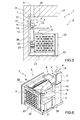
- an articulated duct adapted to put the exit of the flue gases expelled by an extractable fireplace in fluid connection with a flue pipe, present for example in a hearth, is generally designated with the reference numeral 1.
- the term "articulated" is used to mean that the duct according to the present invention comprises at least two connected portions which can move with respect to each other by way of an articulated joint.
- an extractable fireplace 2 which can be fueled by way of a solid fuel, pellets, for the heating of air to be put into the environment in which the fireplace is installed.
- the extractable fireplace 2 is intended to be accommodated in a hearth 27 and be operatively connected, in fluid communication, with a flue pipe which is present in the hearth 27.
- an extractable fireplace 2 comprises a boxlike body 22, in which there is a combustion chamber, a reservoir for the storage of the pellets and forced ventilation means for the flue gases to be evacuated, which are coupled to a slideable support 23 by way of which it is possible to translate the fireplace 2.
- the slideable support 23 makes it possible to translate the extractable fireplace 2 between a first operating position, in which the extractable fireplace 2 is positioned above the slideable support 23, for example within the hearth 27, and a second operating position, in which at least one portion of the extractable fireplace 2 is arranged externally to the hearth 27, supported in a cantilever fashion on the slideable support 23.
- the extractable fireplace 2 equipped with the articulated duct 1 according to the present invention also constitutes the subject matter of the present invention.
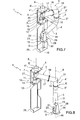
- the articulated duct 1 comprises a first rigid portion 3 and a second rigid portion 4 which are arranged in fluid communication and rotatably connected to each other, at respective ends, by way of a rotating joint, as will be better described below.
- the first portion 3 and the second portion 4 are made of a material that is resistant to combustion gases such as, for example, steel, ferrous alloys, aluminum, or aluminum alloys.
- the first portion 3 is provided with a first end 3' and a second end 3".
- the second portion 4 is provided with a first end 4' and a second end 4".
- At least one section of the first portion 3 and/or at least one section of the second portion 4, in use is inclined with respect to a horizontal plane, not shown in the figures.
- the first portion 3 in use, has at least one inclined section comprised between the first end 3' and the second end 3 ".
- the second portion 4 in use, has at least one inclined section comprised between the first end 4' and the second end 4".
- the inclination of the at least one section of the first portion 3 and of the second portion 4 facilitates the transit and evacuation of the flue gases.
- the inclination of the at least one section of the first portion 3 and/or of the second portion 4 prevents the presence, within the articulated duct 1, of areas of stagnation in which the sedimentation can occur of ash or of the products of combustion present in the flue gases in transit.
- the articulated duct 1 comprises a first rotating joint 5 for the articulated and fluid-tight connection of the second end 3" of the first portion 3 with the first end 4' of the second portion 4.
- the first rotating joint 5 is obtained by introducing at least partially the first end 4' of the second portion 4 into the second end 3" of the first portion 3.
- the second end 3" of the first portion 3 has a greater inside diameter than the outside diameter of the first end 4' of the second portion 4.
- the first portion 3 acts as a support for the second portion 4. More precisely, the first portion 3 supports, at its second end 3", the first end 4'.
- the first rotating joint 5 allows the relative rotation between the first portion 3 and the second portion 4 about a substantially vertical axis of rotation.
- the first rotating joint 5 can comprise any type of joint, provided with two coaxial and mutually opposite ends, which is adapted to ensure the relative rotation thereof about a same axis of rotation and the fluid-tight seal of the joint, without any limitation.
- first rotating joint 5 comprises sealing means, not shown in the figures, in order to ensure the fluid-tight seal at the connection between the first portion 3 and the second portion 4.
- Such sealing means for example, can be provided as a ring gasket accommodated within the first rotating joint 5 at an adapted seat.
- such ring gaskets have an inner lip and an outer lip which are designed to be snugly fitted in use against respective cylindrical surfaces thus producing a fluid-tight seal between them.
- first rotating joint 5 can be provided, with respect to the foregoing description, which are capable of ensuring a rotating and fluid-tight connection between the first portion 3 and the second portion 4 without for this reason departing from the scope of protection claimed herein.
- the first rotating joint 5 identifies, in use, a substantially vertical mobile axis of rotation 6 about which the relative rotation occurs between the first portion 3 and the second portion 4.
- the first axis of rotation 6, in use is translatable along a horizontal direction.
- the articulated duct 1 comprises a bracket 7, which can be anchored, in use, to a wall or to a support, to which the second end 4" of the second portion 4 is rotatably connected.
- the articulated duct 1 comprises a second rotating joint 8 which is operatively connected to the bracket 7 and to the second portion 4, for the rotatable connection of the second end 4" of the second portion 4 to the bracket 7.
- the second rotating joint 8 identifies, in use, a substantially vertical fixed second axis of rotation 9, about which the second end 4" of the second portion 4 can rotate.
- the second portion 4 is operatively connected to the bracket 7, rotating about the second axis of rotation 9.
- the second rotating joint 8 comprises a portion 8' for the connection thereof to one end of a flue pipe, not shown in the accompanying figures.
- the second rotating joint 8 ensures the fluid-tight seal between the second end 4" of the second portion 4 of the articulated duct 1 and the portion 8' for connecting the second rotating joint 8 to a flue pipe.
- the bracket 7 can optionally comprise means 10 for guiding the rotation of the second portion 4 about the second axis of rotation 9.
- the guiding means 10 are positioned at the second end 4".
- the guiding means 10 can comprise a pin 11, which is coupled to the second portion 4 and protrudes below it, at the opposite end with respect to the second end 4", and a cantilever support 13 which can be removably connected to the bracket 7, and is provided with a seat 14 which is substantially complementary to and engageable by the pin 11.
- the bracket 13 is at a lower height than that of the second end 4".
- the pin 11 has a longitudinal axis of symmetry 12 which substantially coincides, in use, with the second axis of rotation 9.
- the guiding means 10 thus provided, if present, keep the second axis of rotation 9 vertically aligned during the rotation of the second portion 4.
- the guiding means 10 enable a fluid rotation, with no sticking, of the second portion 4 about the second axis of rotation 9.
- the guiding means 10 keep the correct alignment between the second portion 4, with reference to the second end 4", and the bracket 7 during the movement of the articulated duct 1.
- the first portion 3 comprises, at its first end 3', a third rotating joint 15.
- the third rotating joint 15 identifies, in use, a substantially vertical mobile third axis of rotation 16.
- the third rotating joint 15 acts as a support and as a rotating and fluid-tight connection for the first end 3' of the first portion 3.
- the first end 3' in use can be connected, in a fluid-tight manner, to a flue gas exit of an extractable fireplace 2.
- the third rotating joint 15 comprises, according to methods known to the person skilled in the art, at least one portion which can be coupled to the flue gas exit of an extractable fireplace 2, which is adapted to not transmit any twisting force to the flue gas exit, so as to not damage it.
- the first rotating joint 5, the second rotating joint 8 and the third rotating joint 15 each comprise at least one sealing element, for example a ring gasket or sealing means in general, not shown in the figures, which are adapted to ensure the fluid-tight seal thereof.
- a sealing element for example a ring gasket or sealing means in general, not shown in the figures, which are adapted to ensure the fluid-tight seal thereof.
- the first axis of rotation 6, the second axis of rotation 9 and the third axis of rotation 16 are arranged substantially parallel to each other and can translate mutually, in use, toward/away from each other along at least one substantially horizontal direction.
- the articulated duct 1 according to the present invention by virtue of the rotating joints 5, 8, 15, can be moved between a first operating position, with reference for example to what is shown in Figures 5 and 6 and 7 , in which the first end 3' of the first portion 3 and the second end 4" of the second portion 4 are brought together, and a second operating position, see Figures 1-3 and 8 , in which the first end 3' of the first portion 3 and the second end 4" of the second portion 4 are arranged mutually distal.
- the second portion 4 comprises a first section 17 and a second section 18 which can be connected, removably, to each other by way of flanged connection means 19.
- Such flanged connection means 19 are of known type per se and, therefore, will not be described further.
- this is particularly advantageous during the connection of the second portion 4 to the flue pipe present in a hearth 27, in that the space within it, generally, is limited.
- the first portion 3 and/or the second portion 4 can comprise at least one through opening 20 for the internal inspection of the first portion 3 and/or of the second portion 4.
- the at least one through opening 20 is provided with a removable cover 21, for closing the through opening 20 in a fluid-tight manner.
- the articulated duct 1 can comprise second guiding means 28 of the first portion 3.
- the second guiding means 28 are provided at the first end 3' of the first portion 3.
- the second guiding means 28 can be provided in a similar manner to that described previously for the guiding means 10.
- the second guiding means 28 can comprise an additional pin 29, which is coupled to the first portion 3 at the first end 3', and a second bracket 30.
- the second bracket 30 is intended, in use, to be associable with the rear portion of an extractable fireplace 2, at the connection between the articulated duct 1 and the extractable fireplace 2.
- the second bracket 30 can have at least one seat with a shape complementary to and engageable with the additional pin 29, which is not shown in detail in the accompanying figures.
- the second bracket 30, therefore, acts as a guiding element for the additional pin 29, keeping it aligned with a vertical axis of rotation during its rotation relative to the second bracket 30.
- the additional pin 29 is associated, protruding externally from the first portion 3, above it, in a diametrically opposite position to that of the first end 3' ( Figures 2 , 7 and 8 ).
- the additional pin 29 has a longitudinal central axis of symmetry 31.
- the second guiding means 28 keep the longitudinal central axis of symmetry 31 aligned with the third axis of rotation 16.
- the longitudinal central axis of symmetry 31 substantially coincides with the third axis of rotation 16.
- the second guiding means 28 thus provided, if present, keep the third axis of rotation 16 aligned with a vertical direction during the rotation of the first portion 3.
- the second guiding means 28 enable a fluid rotation, with no sticking, of the first portion 3 about the third axis of rotation 16.
- the guiding means 10 and the second guiding means 28 ensure, respectively, the support of the second portion 4 and of the first portion 3 during their rotation, keeping them correctly mutually aligned and thus making it possible to reduce the stresses acting on the first rotating joint 5 and/or on the second rotating joint 8 and/or on the third rotating joint 15.
- the guiding means 10 and the second guiding means 28 ensure a fluid movement, without jamming, between the first portion 3 and the second portion 4 and, therefore, of the articulated duct 1.
- the present invention also relates to an extractable fireplace 2 which comprises the above mentioned articulated duct 1.
- the extractable fireplace 2 is of the type comprising a boxlike body 22 in which there are components for the operation of the fireplace 2, which are not shown in the figures, including a combustion chamber, a storage reservoir for the pellets, and forced ventilation means for expelling the flue gases outside the fireplace.
- the extractable fireplace 2 comprises a slideable support 23 which is provided with a fixed footing 24 and with sliding lateral guides 25 which are operatively connected to the sides of the extractable fireplace 2, for the translation of the latter between a first operating position, in which the extractable fireplace 2 is accommodated above the fixed base 24 (see Figures 5 and 6 ), and a second operating position in which the extractable fireplace 2 is arranged at least partially in a cantilever fashion with respect to the fixed base 24 (see Figures 1-3 ), and vice versa.
- the extractable fireplace 2 has, at its rear portion in use, an opening, not shown in the figures, for the exit of the flue gases originating from the combustion chamber, which are expelled by way of the forced ventilation means present in the fireplace 2.
- the exit opening for the flue gases is engageable in a fluid-tight manner with the first end 3' of the first portion 3 of the articulated duct 1 by way of the third rotating joint 15.
- first end 3' of the first portion 3 is connected rotatably and in a fluid-tight manner to the flue gas exit of the extractable fireplace 2 by way of the third rotating joint 15.
- the second guiding means 28 which, in use, are associated by way of the bracket 30 with the rear portion of the extractable fireplace 2.
- the articulated duct 1 can also comprise a supporting element 26, coupled to the fixed base 24 for the support of the bracket 7.
- the bracket 7 which is operatively connected to the second end 4" of the second portion 4 of the articulated duct 1, is coupled to the slideable support 23.
- the supporting element 26 can comprise a cantilever portion to which to operatively connect the second end 4" of the second portion 4 by way of the second rotating joint 8. In such case, the presence of the bracket 7 described previously is rendered unnecessary.
- the articulated duct 1 defines a movable path for the flue gases expelled by the extractable fireplace 2.
- the mobility of the articulated duct 1 makes it possible to modify the geometry of the passage channel of the flue gases and thus ensure a fluid-tight path during the translation of the extractable fireplace 2 along the slideable support 23.
- the first rotating joint 5, the second rotating joint 8 and the third rotating joint 15 make it possible for the first portion 3 and the second portion 4 of the articulated duct 1 to rotate relative to each other, with respect to the extractable fireplace 2 and with respect to the supporting bracket 7, while ensuring the fluid-tight seal of the flue gases that pass through the articulated duct 1 during the movement of the latter.
- the articulated duct 1 when it is operatively connected to the extractable fireplace 2, is not subject to significant fatigue phenomena owing to repeated movements of the extractable fireplace 2.
- first portion 3 and the second portion 4 during the movement of the extractable fireplace 2, and thus of the articulated duct 1 which is operatively connected thereto, are not subject to twisting forces which could compromise their integrity by virtue of the first rotating joint 5 interposed between them, and the second rotating joint 8 and the third rotating joint 15 which are respectively interposed between the second portion 8 and the bracket 7 and between the first portion 3 and the flue gas exit of the extractable fireplace 2.
- the extractable fireplace 2 can be translated from the inside to the outside of a hearth 27, and vice versa, even during its normal operation.
Abstract
Description
- The present invention relates to an articulated duct for conveying the flue gases, expelled by a fireplace, in output to a flue pipe.
- In particular, the present invention relates to an articulated duct which can be connected to a fireplace of the extractable type.
- The present invention furthermore relates to an extractable fireplace which is provided with such an articulated duct for the flue gases.
- In the sector of home heating the use is known of fireplaces, also known as "inserts", which can be accommodated in a hearth, specifically made or pre-existing.
- Typically, within such fireplaces heat is generated as a result of the combustion of a solid fuel, such as wood or pellets. Such heat is then transferred to a flow of air which is taken from the surrounding environment of the fireplace and which is then returned after having been heated. According to a different embodiment, the air thus heated can be conveyed to further environments with respect to the environment where the fireplace is installed, by way of an adapted system of canalization.
- Further variations can also have adapted devices for heat exchange and distribution for the heating and circulation of a fluid, such as water, in an adapted water circuit.
- As is known, a hearth is provided with a flue pipe which is in fluid connection with the outside environment and is adapted to allow, owing to a draw effect, the evacuation of the flue gases outside the environment in which the fireplace is located.
- With reference to the use of solid fuel in the form of pellets, the fireplace comprises a storage reservoir provided with an upper opening for resupplying the solid fuel into the reservoir.
- In this regard, in order to allow the loading of fuel, and specifically in order to promote a convenient access to the upper opening of the reservoir, the fireplace is installed within the hearth so as to rest on a slideable support, which generally comprises a pair of translating guides.
- The support in turn is coupled to the base of the hearth.
- By way of example, each one of the translating guides comprises a fixed portion, which is constrained for example to the base of the hearth, and a movable portion which is constrained to the fireplace.
- With reference to the foregoing, the fireplace can thus be moved between a first operating position, in which the fireplace is accommodated completely within the hearth, and a second operating position, in which the fireplace is extracted almost completely, if not completely, from the hearth.
- Such type of fireplace is also known as an extractable fireplace or extractable insert.
- The fireplace during the combustion of the pellets is arranged in the first operating position described above.
- When it becomes necessary to supply further fuel in the reservoir of the fireplace it is necessary to extract the fireplace from the hearth, by translating it along the slideable guide, until it is brought to the second operating position in which the upper opening of the reservoir is easily accessible.
- Once the operation of loading the fuel is concluded, it is sufficient to push the fireplace back into the hearth, thus bringing it to the first operating position, and activate the fireplace once again.
- The flue gases produced during the operation of the fireplace are expelled toward the flue pipe by way of a flue gas extractor device, which is typically provided in the rear portion of the fireplace.
- Such flue gas extractor device comprises means of forced ventilation which are adapted to withdraw the flue gases from the combustion chamber and send them toward the flue pipe.
- At the exit of the ventilation means there is a duct, the free end of which is selectively engageable in a fluid-tight manner with a box-like element, which is in turn connected in a fluid-tight manner with the flue pipe.
- The seal between the flue gas exit duct and the box-like element is ensured by a ring gasket seal, which is provided with a deformable inner lip, which defines an orifice which is selectively engageable by the flue gas exit duct.
- In brief, with the fireplace arranged in the first operating position, i.e. within the hearth, the flue gas exit duct of the ventilation means is at least partially introduced into the box-like element and is engaged therewith in a fluid-tight manner by way of the ring gasket. Therefore, the flue gases exiting from the combustion chamber are conveyed to the flue pipe without unwanted leaks. When it becomes necessary to supply further fuel in the reservoir, it proceeds extinguishing the fireplace, waiting for it to cool and, then, extracting the fireplace from the hearth.
- A drawback of an extractable fireplace described above is the impossibility of being able to load more fuel into the reservoir during the operation of the fireplace, i.e. during the combustion of pellets.
- In this regard, it should be noted that during the extraction of the fireplace from the hearth the flue gas discharge duct is distanced from the box-like element until it is completely extracted and disengaged therefrom. In such configuration, the flue gases exiting from the combustion chamber are expelled by the forced ventilation means directly into the environment in which the fireplace is installed.
- This is in fact a real hazard, in that the products of combustion can be inhaled directly by anyone who is near the fireplace, with serious consequences.
- In order to be able to extract the fireplace in safety, before anything else it is necessary to extinguish it and switch off the forced ventilation means present therein.
- The above is a considerable disadvantage since in order to be able to introduce further fuel into the reservoir it is necessary to interrupt the operation of the fireplace.
- Furthermore, the ring gasket that acts as a seal for the flue gases exiting toward the flue pipe must be replaced periodically with a new one in that, in use, it is subject to wear as a consequence of repeated extractions/insertions of the fireplace.
- Further types of extractable fireplaces are also known which are provided with a ramp or a duct for loading pellets into the reservoir.
- In essence, the ramp or the duct are provided above the fireplace and are accessible from an opening provided frontally or laterally and above the hearth in which the fireplace is located.
- As can easily be intuited, in order to load the pellets into the reservoir it is sufficient to introduce the pellets through the opening of the duct or of the ramp, described above. The pellets subsequently fall into the reservoir by virtue of gravity.
- The fireplace is still installed on a slideable guide in order to be able to extract it, thus making it accessible if it is necessary to carry out maintenance on it. This type is also not devoid of drawbacks.
- First of all it should be noted that in order to load the pellets it is necessary to access an opening which is arranged at a higher level than that of the fireplace. The loading of pellets, therefore, is particularly inconvenient to carry out. Furthermore, in order to ensure the seal between the flue gas exit duct there is still a ring gasket of the type similar to that described previously.
- It should be noted, finally, that a common drawback to the types of extractable fireplaces described above is the impossibility of being able to verify, with ease, the effective seal between the ring gasket and the flue gas discharge duct.
- An object of the present invention is improve the prior state of the art.
- Within this technical aim, an object of the present invention is to devise an articulated duct for discharging flue gases of a fireplace, of the extractable type, which ensures the seal of the flue gases exiting from the fireplace during the operation thereof, both in a first operating position, in which the fireplace is inserted in the hearth, and in a second operating position in which the fireplace is extracted from the hearth.
- Another object of the present invention is to provide an articulated duct for discharging flue gases which is extremely resistant to the thermal and mechanical stresses to which it is subjected in use, even following repeated cycles of extraction/insertion of the extractable fireplace to which it can be connected.
- Another object of the present invention is to provide an articulated duct for discharging flue gases which is easy to install and maintain, according to a simple solution and with low production costs.
- According to an aspect of the present invention, an articulated duct for flue gases is provided according to
claim 1. - According to a further aspect of the present invention, a fireplace of the extractable type is provided which is provided with an articulated duct as specified in the appended
claim 12. - The dependent claims refer to preferred and advantageous embodiments of the invention.
- Further characteristics and advantages of the present invention will become better apparent from the detailed description of a preferred, but not exclusive, embodiment of an articulated duct for flue gases expelled by an extractable fireplace, which is illustrated for the purposes of non-limiting example in the accompanying drawings wherein:
-
Figure 1 is a front perspective view, slightly from above, of an articulated duct according to the present invention, connected to an extractable fireplace which is arranged in an operating position; -
Figure 2 is a rear perspective view, slightly from above, of the articulated duct inFigure 1 ; -
Figure 3 is a side view of an articulated duct according to the present invention, connected to an extractable fireplace in an extracted position from a hearth; -
Figure 4 is a front elevation view of a detail of the articulated duct according to the present invention; -
Figure 5 is a side view of an articulated duct according to the present invention, connected to an extractable fireplace in a retracted position within a hearth; -
Figure 6 is a rear perspective view, slightly from above, of an articulated duct as inFigure 1 in another operating position; -
Figure 7 is a front perspective view of an articulated duct according to the present invention in an operating position; -
Figure 8 is a front perspective view of the articulated duct inFigure 7 in another operating position. - With reference to the accompanying figures, an articulated duct adapted to put the exit of the flue gases expelled by an extractable fireplace in fluid connection with a flue pipe, present for example in a hearth, is generally designated with the
reference numeral 1. - In the discussion that follows, the term "articulated" is used to mean that the duct according to the present invention comprises at least two connected portions which can move with respect to each other by way of an articulated joint.
- In the following, specific reference will be made to an
extractable fireplace 2 which can be fueled by way of a solid fuel, pellets, for the heating of air to be put into the environment in which the fireplace is installed. - The
extractable fireplace 2, according to a preferred embodiment, is intended to be accommodated in ahearth 27 and be operatively connected, in fluid communication, with a flue pipe which is present in thehearth 27. - As is known, an
extractable fireplace 2 comprises aboxlike body 22, in which there is a combustion chamber, a reservoir for the storage of the pellets and forced ventilation means for the flue gases to be evacuated, which are coupled to aslideable support 23 by way of which it is possible to translate thefireplace 2. - The
slideable support 23 makes it possible to translate theextractable fireplace 2 between a first operating position, in which theextractable fireplace 2 is positioned above theslideable support 23, for example within thehearth 27, and a second operating position, in which at least one portion of theextractable fireplace 2 is arranged externally to thehearth 27, supported in a cantilever fashion on theslideable support 23. - The
extractable fireplace 2 equipped with the articulatedduct 1 according to the present invention also constitutes the subject matter of the present invention. - With regard to the articulated
duct 1, it should be noted that this can also be applied in fireplace stoves, i.e. fireplaces provided with devices for the heating and the distribution of a transfer fluid, such as water, in an adapted heating circuit. - The articulated
duct 1 according to the present invention comprises a firstrigid portion 3 and a secondrigid portion 4 which are arranged in fluid communication and rotatably connected to each other, at respective ends, by way of a rotating joint, as will be better described below. - The
first portion 3 and thesecond portion 4 are made of a material that is resistant to combustion gases such as, for example, steel, ferrous alloys, aluminum, or aluminum alloys. - The
first portion 3 is provided with a first end 3' and asecond end 3". Similarly, thesecond portion 4 is provided with a first end 4' and asecond end 4". - According to an aspect of the present invention, at least one section of the
first portion 3 and/or at least one section of thesecond portion 4, in use, is inclined with respect to a horizontal plane, not shown in the figures. - More precisely, the
first portion 3, in use, has at least one inclined section comprised between the first end 3' and thesecond end 3 ". - Similarly, the
second portion 4, in use, has at least one inclined section comprised between the first end 4' and thesecond end 4". - The inclination of the at least one section of the
first portion 3 and of thesecond portion 4 facilitates the transit and evacuation of the flue gases. - Furthermore, the inclination of the at least one section of the
first portion 3 and/or of thesecond portion 4 prevents the presence, within the articulatedduct 1, of areas of stagnation in which the sedimentation can occur of ash or of the products of combustion present in the flue gases in transit. - An excessive accumulation of ash could partially obstruct or block the articulated
duct 1, reducing its useful flow cross-section and, as a consequence, the efficiency of the draw of the articulatedduct 1. - The articulated
duct 1 according to the present invention comprises a firstrotating joint 5 for the articulated and fluid-tight connection of thesecond end 3" of thefirst portion 3 with the first end 4' of thesecond portion 4. - By way of non-limiting example, the first
rotating joint 5 is obtained by introducing at least partially the first end 4' of thesecond portion 4 into thesecond end 3" of thefirst portion 3. - In this regard, it should be noted that the
second end 3" of thefirst portion 3 has a greater inside diameter than the outside diameter of the first end 4' of thesecond portion 4. - It is in any case possible to have a different connection between the
first portion 3 and thesecond portion 4, in which thesecond end 3" of thefirst portion 3 is introduced into the first end 4' of thesecond portion 4, without for this reason departing from the scope of protection claimed herein. - Effectively, in use, the
first portion 3 acts as a support for thesecond portion 4. More precisely, thefirst portion 3 supports, at itssecond end 3", the first end 4'. - In use, the first
rotating joint 5 allows the relative rotation between thefirst portion 3 and thesecond portion 4 about a substantially vertical axis of rotation. - According to a further version of the present invention, the first rotating joint 5 can comprise any type of joint, provided with two coaxial and mutually opposite ends, which is adapted to ensure the relative rotation thereof about a same axis of rotation and the fluid-tight seal of the joint, without any limitation.
- With regard to the first
rotating joint 5, it should be noted that it comprises sealing means, not shown in the figures, in order to ensure the fluid-tight seal at the connection between thefirst portion 3 and thesecond portion 4. - Such sealing means, for example, can be provided as a ring gasket accommodated within the first rotating joint 5 at an adapted seat.
- As is known, such ring gaskets have an inner lip and an outer lip which are designed to be snugly fitted in use against respective cylindrical surfaces thus producing a fluid-tight seal between them.
- Once again it should be noted that further implementations of the first rotating joint 5 can be provided, with respect to the foregoing description, which are capable of ensuring a rotating and fluid-tight connection between the
first portion 3 and thesecond portion 4 without for this reason departing from the scope of protection claimed herein. - The first
rotating joint 5 identifies, in use, a substantially vertical mobile axis ofrotation 6 about which the relative rotation occurs between thefirst portion 3 and thesecond portion 4. - It should be noted that, as will be better explained in the description that follows, the first axis of
rotation 6, in use, is translatable along a horizontal direction. - According to an aspect of the present invention, the articulated
duct 1 comprises abracket 7, which can be anchored, in use, to a wall or to a support, to which thesecond end 4" of thesecond portion 4 is rotatably connected. - In more detail, the articulated
duct 1 comprises a second rotating joint 8 which is operatively connected to thebracket 7 and to thesecond portion 4, for the rotatable connection of thesecond end 4" of thesecond portion 4 to thebracket 7. - The second
rotating joint 8 identifies, in use, a substantially vertical fixed second axis ofrotation 9, about which thesecond end 4" of thesecond portion 4 can rotate. - Effectively, by virtue of the second
rotating joint 8, thesecond portion 4 is operatively connected to thebracket 7, rotating about the second axis ofrotation 9. - The second
rotating joint 8 comprises a portion 8' for the connection thereof to one end of a flue pipe, not shown in the accompanying figures. - By virtue of the second
rotating joint 8, the rotation of thesecond portion 4 of the articulatedduct 1 about the second axis ofrotation 9 is not transmitted to the flue pipe to which it can be connected in use, with the advantage that the latter is not subjected to twisting. - It should be noted that, similarly to what is described for the first
rotating joint 5, the secondrotating joint 8 ensures the fluid-tight seal between thesecond end 4" of thesecond portion 4 of the articulatedduct 1 and the portion 8' for connecting the second rotating joint 8 to a flue pipe. - According to a version of the present invention, the
bracket 7 can optionally comprise means 10 for guiding the rotation of thesecond portion 4 about the second axis ofrotation 9. - The guiding means 10 are positioned at the
second end 4". - In more detail, the guiding means 10 can comprise a
pin 11, which is coupled to thesecond portion 4 and protrudes below it, at the opposite end with respect to thesecond end 4", and acantilever support 13 which can be removably connected to thebracket 7, and is provided with aseat 14 which is substantially complementary to and engageable by thepin 11. - In use, the
bracket 13 is at a lower height than that of thesecond end 4". - The
pin 11 has a longitudinal axis ofsymmetry 12 which substantially coincides, in use, with the second axis ofrotation 9. - The guiding means 10 thus provided, if present, keep the second axis of
rotation 9 vertically aligned during the rotation of thesecond portion 4. - In this manner, the guiding means 10 enable a fluid rotation, with no sticking, of the
second portion 4 about the second axis ofrotation 9. - In particular, the guiding means 10 keep the correct alignment between the
second portion 4, with reference to thesecond end 4", and thebracket 7 during the movement of the articulatedduct 1. - Similarly to what is described for the
second portion 4, thefirst portion 3 comprises, at its first end 3', a third rotating joint 15. - The third rotating joint 15 identifies, in use, a substantially vertical mobile third axis of
rotation 16. - The third rotating joint 15 acts as a support and as a rotating and fluid-tight connection for the first end 3' of the
first portion 3. - According to an aspect of the present invention, the first end 3' in use can be connected, in a fluid-tight manner, to a flue gas exit of an
extractable fireplace 2. - In this regard, it should be noted that the third rotating joint 15 comprises, according to methods known to the person skilled in the art, at least one portion which can be coupled to the flue gas exit of an
extractable fireplace 2, which is adapted to not transmit any twisting force to the flue gas exit, so as to not damage it. - According to a version of the present invention, the first
rotating joint 5, the secondrotating joint 8 and the third rotating joint 15 each comprise at least one sealing element, for example a ring gasket or sealing means in general, not shown in the figures, which are adapted to ensure the fluid-tight seal thereof. With reference to the foregoing description it should be noted that the first axis ofrotation 6, the second axis ofrotation 9 and the third axis ofrotation 16 are arranged substantially parallel to each other and can translate mutually, in use, toward/away from each other along at least one substantially horizontal direction. - The articulated
duct 1 according to the present invention, by virtue of therotating joints Figures 5 and 6 and7 , in which the first end 3' of thefirst portion 3 and thesecond end 4" of thesecond portion 4 are brought together, and a second operating position, seeFigures 1-3 and8 , in which the first end 3' of thefirst portion 3 and thesecond end 4" of thesecond portion 4 are arranged mutually distal. - According to an aspect of the present invention, the
second portion 4 comprises afirst section 17 and asecond section 18 which can be connected, removably, to each other by way of flanged connection means 19. - Such flanged connection means 19 are of known type per se and, therefore, will not be described further.
- The possibility to connect/disconnect the
first section 17 and thesecond section 18 to/from each other facilitates and simplifies the installation and maintenance of an articulatedduct 1 according to the present invention within a hearth. - In particular, this is particularly advantageous during the connection of the
second portion 4 to the flue pipe present in ahearth 27, in that the space within it, generally, is limited. - With regard to the possibility of carrying out maintenance of the articulated
duct 1, and in particular of checking for the presence of any sediments along the articulatedduct 1, thefirst portion 3 and/or thesecond portion 4 can comprise at least one throughopening 20 for the internal inspection of thefirst portion 3 and/or of thesecond portion 4. - The at least one through
opening 20 is provided with aremovable cover 21, for closing the throughopening 20 in a fluid-tight manner. - According to a version of the present invention, the articulated
duct 1 can comprise second guiding means 28 of thefirst portion 3. - The second guiding means 28 are provided at the first end 3' of the
first portion 3. - The second guiding means 28 can be provided in a similar manner to that described previously for the guiding means 10.
- In more detail, according to a version of the present invention, the second guiding means 28 can comprise an
additional pin 29, which is coupled to thefirst portion 3 at the first end 3', and asecond bracket 30. - The
second bracket 30 is intended, in use, to be associable with the rear portion of anextractable fireplace 2, at the connection between the articulatedduct 1 and theextractable fireplace 2. - The
second bracket 30 can have at least one seat with a shape complementary to and engageable with theadditional pin 29, which is not shown in detail in the accompanying figures. - The
second bracket 30, therefore, acts as a guiding element for theadditional pin 29, keeping it aligned with a vertical axis of rotation during its rotation relative to thesecond bracket 30. - The
additional pin 29 is associated, protruding externally from thefirst portion 3, above it, in a diametrically opposite position to that of the first end 3' (Figures 2 ,7 and 8 ). - The
additional pin 29 has a longitudinal central axis ofsymmetry 31. - In use, the second guiding means 28 keep the longitudinal central axis of
symmetry 31 aligned with the third axis ofrotation 16. - In use, therefore, the longitudinal central axis of
symmetry 31 substantially coincides with the third axis ofrotation 16. - Effectively, the second guiding means 28 thus provided, if present, keep the third axis of
rotation 16 aligned with a vertical direction during the rotation of thefirst portion 3. - In this manner, the second guiding means 28 enable a fluid rotation, with no sticking, of the
first portion 3 about the third axis ofrotation 16. - The guiding means 10 and the second guiding means 28 ensure, respectively, the support of the
second portion 4 and of thefirst portion 3 during their rotation, keeping them correctly mutually aligned and thus making it possible to reduce the stresses acting on the firstrotating joint 5 and/or on the secondrotating joint 8 and/or on the third rotating joint 15. - In this manner, the guiding means 10 and the second guiding means 28 ensure a fluid movement, without jamming, between the
first portion 3 and thesecond portion 4 and, therefore, of the articulatedduct 1. - The present invention also relates to an
extractable fireplace 2 which comprises the above mentioned articulatedduct 1. - The
extractable fireplace 2 is of the type comprising aboxlike body 22 in which there are components for the operation of thefireplace 2, which are not shown in the figures, including a combustion chamber, a storage reservoir for the pellets, and forced ventilation means for expelling the flue gases outside the fireplace. - It should be noted that the internal components of an
extractable fireplace 2 are not described in detail in that they do not form the subject matter of the present invention. - Likewise, the
extractable fireplace 2 comprises aslideable support 23 which is provided with a fixedfooting 24 and with sliding lateral guides 25 which are operatively connected to the sides of theextractable fireplace 2, for the translation of the latter between a first operating position, in which theextractable fireplace 2 is accommodated above the fixed base 24 (seeFigures 5 and 6 ), and a second operating position in which theextractable fireplace 2 is arranged at least partially in a cantilever fashion with respect to the fixed base 24 (seeFigures 1-3 ), and vice versa. - The
extractable fireplace 2 has, at its rear portion in use, an opening, not shown in the figures, for the exit of the flue gases originating from the combustion chamber, which are expelled by way of the forced ventilation means present in thefireplace 2. - The exit opening for the flue gases is engageable in a fluid-tight manner with the first end 3' of the
first portion 3 of the articulatedduct 1 by way of the third rotating joint 15. - In detail, the first end 3' of the
first portion 3 is connected rotatably and in a fluid-tight manner to the flue gas exit of theextractable fireplace 2 by way of the third rotating joint 15. - Likewise provided at the first end 3' of the
first portion 3 are the second guiding means 28 which, in use, are associated by way of thebracket 30 with the rear portion of theextractable fireplace 2. - With regard to the connection of the articulated
duct 1 to theslideable support 23, it should be noted that the latter can also comprise a supportingelement 26, coupled to the fixedbase 24 for the support of thebracket 7. - By way of the supporting
element 26 thebracket 7, which is operatively connected to thesecond end 4" of thesecond portion 4 of the articulatedduct 1, is coupled to theslideable support 23. - In this manner a stable support is provided for the articulated
duct 1, with particular reference to supporting thesecond end 4" of thesecond portion 4. - According to a further variation of the present invention, not shown in the figures, the supporting
element 26 can comprise a cantilever portion to which to operatively connect thesecond end 4" of thesecond portion 4 by way of the secondrotating joint 8. In such case, the presence of thebracket 7 described previously is rendered unnecessary. - According to an object of the present invention, the articulated
duct 1 defines a movable path for the flue gases expelled by theextractable fireplace 2. - The mobility of the articulated
duct 1 makes it possible to modify the geometry of the passage channel of the flue gases and thus ensure a fluid-tight path during the translation of theextractable fireplace 2 along theslideable support 23. - The first
rotating joint 5, the secondrotating joint 8 and the third rotating joint 15 make it possible for thefirst portion 3 and thesecond portion 4 of the articulatedduct 1 to rotate relative to each other, with respect to theextractable fireplace 2 and with respect to the supportingbracket 7, while ensuring the fluid-tight seal of the flue gases that pass through the articulatedduct 1 during the movement of the latter. - It should be noted furthermore that the articulated
duct 1, when it is operatively connected to theextractable fireplace 2, is not subject to significant fatigue phenomena owing to repeated movements of theextractable fireplace 2. - In substance, it is emphasized that the
first portion 3 and thesecond portion 4 during the movement of theextractable fireplace 2, and thus of the articulatedduct 1 which is operatively connected thereto, are not subject to twisting forces which could compromise their integrity by virtue of the first rotating joint 5 interposed between them, and the secondrotating joint 8 and the third rotating joint 15 which are respectively interposed between thesecond portion 8 and thebracket 7 and between thefirst portion 3 and the flue gas exit of theextractable fireplace 2. - With reference to the foregoing, it is evident that the
extractable fireplace 2 can be translated from the inside to the outside of ahearth 27, and vice versa, even during its normal operation. - This is a considerable advantage, in that it is possible to supply fuel in the reservoir of the
extractable fireplace 2 without necessarily having to require the extinguishing of the fireplace. - In this manner a continuity of operation is ensured of the
extractable fireplace 2. - It should be noted furthermore that the implementation of the articulated
duct 1 in anextractable fireplace 2 according to the present invention simplifies and reduces the times for maintenance of the fireplace in that in order to be able to extract thefireplace 2 from thehearth 27 it is not necessary to remove the articulatedduct 1 or parts thereof. - The invention, thus conceived, is susceptible of numerous modifications and variations, all of which are within the scope of the appended claims. Moreover, all the details may be substituted by other, technically equivalent elements. In practice the materials employed, as well as the contingent dimensions and shapes, may be any according to requirements without for this reason departing from the scope of protection claimed herein.
Claims (15)
- Articulated duct (1), for discharging flue gases coming out from a fireplace outlet, said duct (1) comprising a first portion (3) that is and a second portion (4) that is rigid in fluid communication with one another, said first portion (3) having a first end (3') and a second end (3 "), said second portion (4) having a first end (4') and a second end (4"), characterised in that it includes a first rotating joint (5) for the articulated and fluid-tight connection of said second end (3") of said first portion (3) with said first end (4') of said second portion (4) wherein said first rotating joint (5) define, in use, a substantially vertical first axis (6), translatable along a horizontal direction, for the mutual rotation between said first portion (3) and said second portion (4).
- Articulated duct (1) according to claim 1, wherein said first portion (3) and/or said second portion (4), in use, comprising at least a section inclined with respect to a horizontal plane, wherein said at least one inclined section is comprised between said first end (3') and said second end (3") of said first portion (3) and/or between said first end (4') and said second end (4") of said second portion (4).
- Articulated duct (1) according to claim 1 or 2, comprising a bracket (7), anchorable to a wall or a support, to which said second end (4") of said second portion (4) is rotatable connected by means of a second fluid-tight rotating joint (8).
- Articulated duct (1) according to the previous claim, wherein said second rotating joint (8) identifies, in use, a substantially vertical second axis of rotation (9), that is fixed, for the rotation of said second end (4") of said second portion (4).
- Articulated duct (1) according to the previous claim, comprising means (10) for guiding the rotation of said second end (4") of said second portion (4) around said second axis of rotation (9).
- Articulated duct (1) according to the previous claim, wherein said guiding means (10) comprise a pin (11), externally protruding anchored from said second portion (4), at said second end (4"), said pin (11) having a longitudinal axis of symmetry (12) coinciding with said second axis of rotation (9), said guiding means (10) comprising a cantilevered element (13), connectable to said bracket (7), provided with a seat (14) substantially complementary to and engageable with said pin (11).
- Articulated duct (1) according to any one of the previous claims, wherein said first portion (3) comprises at said first end (3') a third fluid-tight rotating joint (15), for the rotation of said first end (3') around a substantially vertical third axis of rotation (16).
- Articulated duct (1) according to any one of the previous claims, comprising second guiding means (28) for guiding the rotation of said first portion (3) around said third axis of rotation (16).
- Articulated duct (1) according to any one of the previous claims, wherein said first axis of rotation (5), said second axis of rotation (9) and said third axis of rotation (16) are arranged parallel to each other and are mutually translatable, in use, along a substantially horizontal direction.
- Articulated duct (1) according to any one of the previous claims, wherein said second portion (4) comprises a first section (17) and a second section (18) connectable to one another, in a removable manner, by flanged connecting means (19).
- Articulated duct (1) according to any previous claims, where said first portion (3) and/or said second portion (4) comprise at least one through opening (20) for the internal inspection of said first portion (3) and/or of said second portion (4), and at least one cover (21), connectable in a removable manner to said at least one through opening (20), for fluid-tight closing said at least one opening (20).
- Extractable fireplace (2) comprising
a boxlike body (22), inside which a combustion chamber is provided,
a slideable support (23), provided with a fixed base (24) and sliding lateral guides (25) operatively connected to said extractable fireplace (2), for the translation of said extractable fireplace (2) between one first operating position, in which said extractable fireplace (2) is positioned above said fixed base (24), and a second operating position, in which said extractable fireplace (2) is placed at least partly in a cantilevered position with respect to said fixed base (24), and vice versa,
characterised in that it comprises an articulated duct (1) for the flue gases discharged by said extractable fireplace according to any one of the claims 1 to 11. - Extractable fireplace (2) according to claim 12, wherein said first end (3') of said first portion (3) of said articulated duct (1) is connected in a tight manner to the fume outlet of said extractable fireplace (2) through a third rotating joint (15).
- Extractable fireplace (2) according to claim 12, wherein said slideable support (23) comprises a support element (26) for the connection of a bracket (7) supporting said second end (4") of said second portion (4) or for the connection of said second rotating joint (8) that is operatively connected to said second end (4") of said second portion (4).
- Extractable fireplace (2) according to claim 12, wherein said second guiding means (28) of said articulated duct (1) are associated, in use, with a rear portion of said extractable fireplace (2).
Applications Claiming Priority (1)
| Application Number | Priority Date | Filing Date | Title |
|---|---|---|---|
| ITVR20140156 | 2014-05-29 |
Publications (1)
| Publication Number | Publication Date |
|---|---|
| EP2950000A1 true EP2950000A1 (en) | 2015-12-02 |
Family
ID=51230120
Family Applications (1)
| Application Number | Title | Priority Date | Filing Date |
|---|---|---|---|
| EP15169937.8A Withdrawn EP2950000A1 (en) | 2014-05-29 | 2015-05-29 | Articulated duct for extractable fireplace and extractable fireplace provided with such articulated duct |
Country Status (1)
| Country | Link |
|---|---|
| EP (1) | EP2950000A1 (en) |
Cited By (1)
| Publication number | Priority date | Publication date | Assignee | Title |
|---|---|---|---|---|
| EP3770505A1 (en) * | 2019-07-23 | 2021-01-27 | Karl Stefan Riener | Furnace with movable furnace member |
Citations (3)
| Publication number | Priority date | Publication date | Assignee | Title |
|---|---|---|---|---|
| DE23285C (en) * | a. jutteau in Thiais, Frankreich | Fireplace with pull-out fire basket | ||
| DE70340C (en) * | F. HOUBEN in Aachen, Edelstrafse 5 | Gas stove with pull-out heater | ||
| FR2649473A1 (en) * | 1989-07-04 | 1991-01-11 | Muller Cie | Device for connecting up the flue and/or air inlet and/or hot air outlet pipes of built-in gas-fired heating appliances |
-
2015
- 2015-05-29 EP EP15169937.8A patent/EP2950000A1/en not_active Withdrawn
Patent Citations (3)
| Publication number | Priority date | Publication date | Assignee | Title |
|---|---|---|---|---|
| DE23285C (en) * | a. jutteau in Thiais, Frankreich | Fireplace with pull-out fire basket | ||
| DE70340C (en) * | F. HOUBEN in Aachen, Edelstrafse 5 | Gas stove with pull-out heater | ||
| FR2649473A1 (en) * | 1989-07-04 | 1991-01-11 | Muller Cie | Device for connecting up the flue and/or air inlet and/or hot air outlet pipes of built-in gas-fired heating appliances |
Cited By (2)
| Publication number | Priority date | Publication date | Assignee | Title |
|---|---|---|---|---|
| EP3770505A1 (en) * | 2019-07-23 | 2021-01-27 | Karl Stefan Riener | Furnace with movable furnace member |
| DE102019005110B4 (en) | 2019-07-23 | 2023-03-23 | Karl Stefan Riener | OVEN WITH MOVABLE OVEN PART |
Similar Documents
| Publication | Publication Date | Title |
|---|---|---|
| CN106322459B (en) | Kitchen range steam box all-in-one machine | |
| EP2950000A1 (en) | Articulated duct for extractable fireplace and extractable fireplace provided with such articulated duct | |
| CN101225914B (en) | Automatic abutting joint for gas pipe | |
| CN204902222U (en) | Gas combustion hot water boiler | |
| CN205783125U (en) | Empty burning prevention device of cooking range and there is the commercial stove of this anti-empty burning device | |
| CN207702451U (en) | A kind of boiler returning charge wind feedway | |
| US3439910A (en) | Back draft valve for blast furnace installation | |
| KR101410148B1 (en) | Coke discharging apparatus for cokes dry quenching facilities | |
| CN209386564U (en) | Combustor outer casing and water heater | |
| CN103234193B (en) | A kind of burner | |
| CN206556018U (en) | Inversion type heat storage burner | |
| CN206380684U (en) | A kind of good tobacco curing barn fume extractor of thermal diffusivity | |
| CN206247388U (en) | Steam coal flame detecting device | |
| CN204346191U (en) | A kind of heating furnace fume extractor | |
| CN207395501U (en) | A kind of waste heat of cupola furnace retracting device | |
| CN206339879U (en) | The supporting temperature control equipment with 20L spherical blast test systems | |
| CN206875688U (en) | A kind of gas-heating water heater casing | |
| WO2020134164A1 (en) | Smart fire extinguisher controller | |
| CN207133214U (en) | The guide frame of fire resistant doorsets heatproof test mechanism | |
| CN106197079B (en) | Heat exchanger and storage tank with heat exchanger | |
| CN214307191U (en) | Combustor cooling air lets in structure | |
| CN205774633U (en) | A kind of flue for oxygen inclined blown converter fire door | |
| CN204534690U (en) | A kind of closed blowing type gas large stove | |
| CN204630029U (en) | A kind of continuous heat supply homogeneous solution-type reactor being convenient to scale removal | |
| CN212451541U (en) | Furnace door plate lifting mechanism |
Legal Events
| Date | Code | Title | Description |
|---|---|---|---|
| AK | Designated contracting states |
Kind code of ref document: A1 Designated state(s): AL AT BE BG CH CY CZ DE DK EE ES FI FR GB GR HR HU IE IS IT LI LT LU LV MC MK MT NL NO PL PT RO RS SE SI SK SM TR |
|
| AX | Request for extension of the european patent |
Extension state: BA ME |
|
| PUAI | Public reference made under article 153(3) epc to a published international application that has entered the european phase |
Free format text: ORIGINAL CODE: 0009012 |
|
| 17P | Request for examination filed |
Effective date: 20160601 |
|
| RBV | Designated contracting states (corrected) |
Designated state(s): AL AT BE BG CH CY CZ DE DK EE ES FI FR GB GR HR HU IE IS IT LI LT LU LV MC MK MT NL NO PL PT RO RS SE SI SK SM TR |
|
| R17P | Request for examination filed (corrected) |
Effective date: 20160601 |
|
| 17Q | First examination report despatched |
Effective date: 20161219 |
|
| STAA | Information on the status of an ep patent application or granted ep patent |
Free format text: STATUS: THE APPLICATION IS DEEMED TO BE WITHDRAWN |
|
| 18D | Application deemed to be withdrawn |
Effective date: 20170503 |