EP2949986B1 - Réservoir d'huile pour générateur de turbine éolienne, unité de stockage de l'huile et générateur de turbine éolienne - Google Patents
Réservoir d'huile pour générateur de turbine éolienne, unité de stockage de l'huile et générateur de turbine éolienne Download PDFInfo
- Publication number
- EP2949986B1 EP2949986B1 EP15156772.4A EP15156772A EP2949986B1 EP 2949986 B1 EP2949986 B1 EP 2949986B1 EP 15156772 A EP15156772 A EP 15156772A EP 2949986 B1 EP2949986 B1 EP 2949986B1
- Authority
- EP
- European Patent Office
- Prior art keywords
- oil
- wind turbine
- oil tank
- turbine generator
- tank
- Prior art date
- Legal status (The legal status is an assumption and is not a legal conclusion. Google has not performed a legal analysis and makes no representation as to the accuracy of the status listed.)
- Not-in-force
Links
- 238000005192 partition Methods 0.000 claims description 80
- 238000007667 floating Methods 0.000 claims description 34
- 230000014509 gene expression Effects 0.000 claims description 29
- 238000004891 communication Methods 0.000 claims description 8
- 230000001133 acceleration Effects 0.000 claims description 7
- 230000005484 gravity Effects 0.000 claims description 7
- 238000005452 bending Methods 0.000 claims description 6
- 238000010438 heat treatment Methods 0.000 claims description 6
- 238000011084 recovery Methods 0.000 claims description 4
- 239000003921 oil Substances 0.000 description 482
- 230000005540 biological transmission Effects 0.000 description 19
- 238000005096 rolling process Methods 0.000 description 9
- 238000010586 diagram Methods 0.000 description 6
- 230000000694 effects Effects 0.000 description 2
- 238000009434 installation Methods 0.000 description 2
- 238000012423 maintenance Methods 0.000 description 2
- 238000012546 transfer Methods 0.000 description 2
- 239000006185 dispersion Substances 0.000 description 1
- 239000000314 lubricant Substances 0.000 description 1
- 239000010687 lubricating oil Substances 0.000 description 1
- 239000000463 material Substances 0.000 description 1
- 238000012986 modification Methods 0.000 description 1
- 230000004048 modification Effects 0.000 description 1
- 238000010248 power generation Methods 0.000 description 1
- 238000013517 stratification Methods 0.000 description 1
Images





Classifications
-
- F—MECHANICAL ENGINEERING; LIGHTING; HEATING; WEAPONS; BLASTING
- F16—ENGINEERING ELEMENTS AND UNITS; GENERAL MEASURES FOR PRODUCING AND MAINTAINING EFFECTIVE FUNCTIONING OF MACHINES OR INSTALLATIONS; THERMAL INSULATION IN GENERAL
- F16H—GEARING
- F16H57/00—General details of gearing
- F16H57/04—Features relating to lubrication or cooling or heating
- F16H57/045—Lubricant storage reservoirs, e.g. reservoirs in addition to a gear sump for collecting lubricant in the upper part of a gear case
- F16H57/0452—Oil pans
-
- F—MECHANICAL ENGINEERING; LIGHTING; HEATING; WEAPONS; BLASTING
- F03—MACHINES OR ENGINES FOR LIQUIDS; WIND, SPRING, OR WEIGHT MOTORS; PRODUCING MECHANICAL POWER OR A REACTIVE PROPULSIVE THRUST, NOT OTHERWISE PROVIDED FOR
- F03D—WIND MOTORS
- F03D80/00—Details, components or accessories not provided for in groups F03D1/00 - F03D17/00
-
- F—MECHANICAL ENGINEERING; LIGHTING; HEATING; WEAPONS; BLASTING
- F16—ENGINEERING ELEMENTS AND UNITS; GENERAL MEASURES FOR PRODUCING AND MAINTAINING EFFECTIVE FUNCTIONING OF MACHINES OR INSTALLATIONS; THERMAL INSULATION IN GENERAL
- F16H—GEARING
- F16H57/00—General details of gearing
- F16H57/04—Features relating to lubrication or cooling or heating
- F16H57/0412—Cooling or heating; Control of temperature
-
- F—MECHANICAL ENGINEERING; LIGHTING; HEATING; WEAPONS; BLASTING
- F16—ENGINEERING ELEMENTS AND UNITS; GENERAL MEASURES FOR PRODUCING AND MAINTAINING EFFECTIVE FUNCTIONING OF MACHINES OR INSTALLATIONS; THERMAL INSULATION IN GENERAL
- F16H—GEARING
- F16H57/00—General details of gearing
- F16H57/04—Features relating to lubrication or cooling or heating
- F16H57/0447—Control of lubricant levels, e.g. lubricant level control dependent on temperature
-
- F—MECHANICAL ENGINEERING; LIGHTING; HEATING; WEAPONS; BLASTING
- F16—ENGINEERING ELEMENTS AND UNITS; GENERAL MEASURES FOR PRODUCING AND MAINTAINING EFFECTIVE FUNCTIONING OF MACHINES OR INSTALLATIONS; THERMAL INSULATION IN GENERAL
- F16H—GEARING
- F16H57/00—General details of gearing
- F16H57/04—Features relating to lubrication or cooling or heating
- F16H57/045—Lubricant storage reservoirs, e.g. reservoirs in addition to a gear sump for collecting lubricant in the upper part of a gear case
-
- F—MECHANICAL ENGINEERING; LIGHTING; HEATING; WEAPONS; BLASTING
- F16—ENGINEERING ELEMENTS AND UNITS; GENERAL MEASURES FOR PRODUCING AND MAINTAINING EFFECTIVE FUNCTIONING OF MACHINES OR INSTALLATIONS; THERMAL INSULATION IN GENERAL
- F16N—LUBRICATING
- F16N39/00—Arrangements for conditioning of lubricants in the lubricating system
- F16N39/04—Arrangements for conditioning of lubricants in the lubricating system by heating
-
- F—MECHANICAL ENGINEERING; LIGHTING; HEATING; WEAPONS; BLASTING
- F05—INDEXING SCHEMES RELATING TO ENGINES OR PUMPS IN VARIOUS SUBCLASSES OF CLASSES F01-F04
- F05B—INDEXING SCHEME RELATING TO WIND, SPRING, WEIGHT, INERTIA OR LIKE MOTORS, TO MACHINES OR ENGINES FOR LIQUIDS COVERED BY SUBCLASSES F03B, F03D AND F03G
- F05B2260/00—Function
- F05B2260/40—Transmission of power
- F05B2260/406—Transmission of power through hydraulic systems
-
- Y—GENERAL TAGGING OF NEW TECHNOLOGICAL DEVELOPMENTS; GENERAL TAGGING OF CROSS-SECTIONAL TECHNOLOGIES SPANNING OVER SEVERAL SECTIONS OF THE IPC; TECHNICAL SUBJECTS COVERED BY FORMER USPC CROSS-REFERENCE ART COLLECTIONS [XRACs] AND DIGESTS
- Y02—TECHNOLOGIES OR APPLICATIONS FOR MITIGATION OR ADAPTATION AGAINST CLIMATE CHANGE
- Y02E—REDUCTION OF GREENHOUSE GAS [GHG] EMISSIONS, RELATED TO ENERGY GENERATION, TRANSMISSION OR DISTRIBUTION
- Y02E10/00—Energy generation through renewable energy sources
- Y02E10/70—Wind energy
- Y02E10/72—Wind turbines with rotation axis in wind direction
Definitions
- the present disclosure relates to an oil tank for a wind turbine generator, an oil storing unit, and a wind turbine generator.
- a nacelle supported on a tower of a wind turbine generator may include an oil tank for storing oil used in an oil using unit included in a wind turbine generator.
- the oil using unit is, for instance, a gearbox using lubricant oil, a hydraulic pump or a hydraulic motor using working oil.
- Patent Document 1 describes a configuration in which the region inside an oil tank is divided into two oil chambers by a partition wall so as to prevent overflow of oil between the two oil chambers by use of the partition wall.
- Patent Document 1 US Patent Application Pub. No. 2013-0336764
- EP 2 535 633 A1 discloses a lubricating oil heating mechanism, a gear mechanism, and a wind power generation device.
- a phenomenon in which oil sways due to sway of a tower caused by wind load received by a wind turbine which is the sloshing phenomenon, occurs in an oil tank disposed in a nacelle.
- the sloshing phenomenon can be restricted by dividing the region inside the oil tank by a partition wall into a plurality of oil chambers, providing such a partition wall tends to cause the oil temperatures to be uneven between the respective oil chambers separated by the partition wall.
- the oil to be recovered tends to have a temperature higher than that of the oil in the oil tank, which tends to cause the oil temperatures in the respective oil chambers to be uneven if the region inside the oil tank is divided into the plurality of oil chambers by the partition wall.
- Patent Document 1 describes a configuration in which the heat transfer of the partition wall itself dividing the region inside the oil tank is used to exchange heat between the oil chambers.
- the amount of heat which can be exchanged by the heat transfer of the partition wall itself as described above is limited.
- the equalizing effect for the oil temperatures of the above configuration is also limited.
- an object of at least one embodiment of the present invention is to provide an oil tank for a wind turbine generator, which is configured to recover oil used in an oil using unit, and which is capable of effectively equalizing the oil temperatures in the tank while restricting the sloshing phenomenon.
- the oil tank for a wind turbine generator configured to recover the oil having been used in the oil using unit, it is possible to restrict the sloshing phenomenon and to equalize the oil temperatures in the tank effectively.
- an expression of relative or absolute arrangement such as “in a direction”, “along a direction”, “parallel”, “orthogonal”, “centered”, “concentric” and “coaxial” shall not be construed as indicating only the arrangement in a strict literal sense, but also includes a state where the arrangement is relatively displaced by a tolerance, or by an angle or a distance whereby it is possible to achieve the same function.
- an expression of a shape such as a rectangular shape or a cylindrical shape shall not be construed as only the geometrically strict shape, but also includes a shape with unevenness or chamfered corners within the range in which the same effect can be achieved.
- FIG. 1 is a schematic diagram of an overall configuration of a wind turbine generator according to one embodiment.
- a wind turbine generator 100 illustrated in FIG. 1 includes a wind turbine rotor 2 which rotates upon receiving wind, a hydraulic transmission 4 (an oil using unit) which increases the rotation speed of the wind turbine rotor 2, a generator to which rotation energy of the wind turbine rotor 2 is transmitted via the hydraulic transmission 4 and which generates electric power, an oil tank 28 for storing oil (working oil) which is to be used in the hydraulic transmission 4, a nacelle 7 for accommodating the hydraulic transmission 4, the generator 6, and the oil tank 28, and a tower 14 supporting the nacelle 7.
- the wind turbine generator 100 is a floating wind turbine generator where the tower 14 is disposed on a floating body 18 moored by mooring cables 16 fixed to the bottom of the sea so as to be installed floating on the sea surface.
- the wind turbine rotor 2 includes wind turbine blades 8, a hub 10 to which the wind turbine blades 8 are mounted, and a rotation shaft 12 coupled to the hub 10. In this way, the entire wind turbine rotor 2 is rotated by wind power received by the wind turbine blades 8 so that the rotation is inputted into the hydraulic transmission 4 from the rotation shaft 12.
- the rotation shaft 12 of the wind turbine rotor 2 is housed in the nacelle 7 which is rotatably supported on the tower 14.
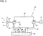
- the hydraulic transmission 4 includes a hydraulic pump 20 driven by rotation of the rotation shaft 12, a hydraulic motor 22 coupled to the generator 6, and a high pressure oil line 24 and a low pressure oil line 26 disposed between the hydraulic pump 20 and the hydraulic motor 22.
- the outlet side of the hydraulic pump 20 is connected to the inlet side of the hydraulic motor 22 via the high pressure oil line 24, while the inlet side of the hydraulic pump 20 is connected to the outlet side of the hydraulic motor 22 via the low pressure oil line 26.
- the working oil (high pressure oil) discharged from the hydraulic pump 20 flows into the hydraulic motor 22 via the high pressure oil line 24, and drives the hydraulic motor 22. As a result, electric power is generated in the generator 6 coupled to the hydraulic motor 22.
- the working oil (low pressure oil) having performed work in the hydraulic motor 22 flows into the hydraulic pump 20 via the low pressure oil line 26, has its pressure increased by the hydraulic pump 20, and then flows again into the hydraulic motor 22 via the high pressure oil line 24.
- FIG. 2 is an exemplary configuration of a hydraulic circuit including a hydraulic transmission and an oil tank illustrated in FIG. 1 .
- the hydraulic circuit 30 includes a supply line 32 (oil supply line) connecting the low pressure oil line 26 and the oil tank 28, for supplying working oil to the low pressure oil line 26 from the oil tank 28, and a boost pump 35 disposed on the supply line 32 to supply the working oil to the low pressure oil line 26 from the oil tank 28.
- a supply line 32 oil supply line
- boost pump 35 disposed on the supply line 32 to supply the working oil to the low pressure oil line 26 from the oil tank 28.
- the hydraulic circuit 30 illustrated in FIG. 2 includes a motoring line 36 (oil supply line) and a motoring pump 38.
- the motoring line 36 is to supply the working oil to the hydraulic pump 20 to cause motoring of the hydraulic pump 20 temporarily.
- the motoring line 36 is configured to be capable of bringing the oil tank 28 into communication with hydraulic chambers (not illustrated) of the hydraulic pump 20.
- the motoring pump 38 may be configured to be capable of supplying pressurized oil to the hydraulic chambers (not illustrated) of the hydraulic pump 20 via the motoring line 36.
- Motoring of the hydraulic pump 20 is executed, for instance, when moving the wind turbine rotor 2 to a predetermined angular position during maintenance of the wind turbine generator 100, or when moving the rotation shaft of the hydraulic pump 20 to a predetermined angular position during maintenance of the hydraulic pump 20.
- the hydraulic circuit 30 illustrated in FIG. 2 includes the first drain line 40 for recovering the working oil having leaked from the hydraulic pump 20 to the oil tank 28, the second drain line 42 for recovering the working oil having leaked from the hydraulic motor 22 to the oil tank 28, and a relief line 34 having a relief valve 44 for recovering the working oil from the low pressure oil line 26 to the oil tank 28 when the pressure of the low pressure oil line 26 exceeds a setting pressure, all of which serving as oil recovery lines.
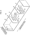
- FIG. 3 is a schematic perspective view of an internal structure of the oil tank illustrated in FIGs. 1 and 2 .
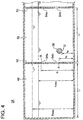
- FIG. 4 is a cross-sectional view of the oil tank illustrated in FIG. 3 taken along the line A-A.
- the oil tank 28 at least includes the first oil chamber 48 and second oil chamber 50 for storing the oil, and a partition wall 52 for separating the first oil chamber 48 and the second oil chamber 50 from each other.
- the oil tank 28 has a cuboid shape or a cubic shape.
- the partition wall 52 is arranged so that the first oil chamber 48 and the second oil chamber 50 each have a cuboid shape or a cubic shape.
- the above first drain line 40, second drain line 42 and relief line 34 are connected to the first oil chamber so that the oil, after being used in various parts of the hydraulic transmission 4 and having obtained a relatively high temperature, is recovered from each line to the first oil chamber 48.
- the above supply line 32 and motoring line 36 are connected to the second oil chamber 50, so that the oil is supplied to the supply line 32 or the motoring line 36 from the second oil chamber 50 while the hydraulic transmission 4 is in operation or while the hydraulic pump 20 is motoring.
- the partition wall 52 illustrated in FIGs. 3 and 4 includes at least two openings 54 (54a, 54b) through which the first oil chamber 48 and the second oil chamber 50 communicate with each other so as to allow movement of the oil between the first oil chamber 48 and the second oil chamber 50.
- the oil tank 28 at least includes the first oil chamber 48 and the second oil chamber 50 separated by the partition wall 52 as described above, it is possible to restrict sloshing of the oil as compared to an oil tank with a single oil chamber.
- the partition wall 52 includes the two openings 54 through which the first oil chamber 48 and the second oil chamber 50 communicate with each other so as to allow movement of the oil between the first oil chamber 48 and the second oil chamber 50, it is possible to effectively equalize the oil temperatures of the first oil chamber 48 and the second oil chamber 50 by shifting of the oil via the openings 54 even if the oil is recovered to the first oil chamber 48 after being used in the hydraulic transmission 4 and having obtained a relatively high temperature.
- the partition wall 52 including the at least two openings 54 is not limited to the embodiments illustrated in FIGs. 3 and 4 .
- the partition wall 52 may include three or more openings, or the partition wall 52 may be a perforated plate including a plurality of openings.
- the at least two openings 54 include the first opening 54a and the second opening 54b disposed below the first opening 54a.
- the oil which has moved from the first oil chamber 48 to the second oil chamber 50, or vice versa, through the first opening 54a, can return to the first oil chamber 48 from the second oil chamber 50, or vice versa, through the second opening 54b by convection of the oil. That is, it is possible to circulate the oil between the first oil chamber 48 and the second oil chamber 50 utilizing the convection of the oil, which makes it possible to equalize the oil temperatures of the first oil chamber 48 and the second oil chamber 50 even more effectively.
- the oil tank 28 illustrated in FIG. 3 includes, in addition to the first oil chamber 48 and the second oil chamber 50, the third oil chamber 51 disposed adjacent to the second oil chamber 50, and a partition wall 53 separating the second oil chamber 50 and the third oil chamber 51.
- the third oil chamber 51 includes an oil heater 49, and the partition wall 53 includes at least two openings 55 (55a to 55d).
- the number of oil chambers in the oil tank 28, however, is not particularly limited. Providing at least one partition wall to create two or more oil chambers makes it possible to restrict sloshing of the oil as compared to the case of a single oil chamber.
- the interior of the oil tank 28 is in communication with the atmospheric air so that the internal pressure of the oil tank 28 illustrated in FIG. 3 becomes the atmospheric pressure. In this way, it is possible to restrict the fluctuation of the internal pressure of the oil tank 28.
- the oil tank 28 further includes an oil heater 56 for heating the oil, disposed in the first oil chamber 48 or the second oil chamber 50.
- the oil positioned below the lower end position of the oil heater 56 is stratified and it is difficult to flow by convection.
- the lower end position P of the second opening 54b is lower than the lower end position Q of the oil heater 56 as illustrated in FIG. 6 (a case satisfying the relationship h 2 ⁇ h a , where h 2 is the height of the lower end position P of the second opening 54b from the oil-tank bottom surface B and h a is the height of the lower end position Q of the oil heater 56 from the oil-tank bottom surface B)
- the oil positioned below the lower end position Q of the oil heater 56 is stratified, as illustrated in FIG. 7 .
- good circulation of the oil via the first opening 54a and the second opening 54b may not be achieved.
- the lower end position P of the second opening 54b is above the lower end position Q of the oil heater 56, as illustrated in FIG. 4 .
- the relationship h 2 > h a is satisfied.
- the convection of the oil makes it easy for the oil, which has moved from the second oil chamber 50 to the first oil chamber 48 through the first opening 54a, to return to the second oil chamber 50 from the first oil chamber 48 through the second opening 54b.
- h 1 ⁇ F min is satisfied, where h 1 is the height of the upper end position R of the first opening 54a, and F min is the minimum possible height that the oil surface in the oil tank 28 reaches while the hydraulic transmission 4 is in operation.
- both of the first opening 54a and the second opening 54b are under the oil surface, which makes it possible to maintain the oil circulation utilizing the above convection between the first oil chamber 48 and the second oil chamber 50, regardless of the operation state of the hydraulic transmission 4.
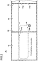
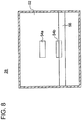
- FIG. 8 is a view of the oil tank 28 in FIG. 3 taken in the direction of arrow B.
- the second opening 54b is disposed at a position where at least a part of the second opening 54b overlaps with the oil heater 56 as seen from the direction B perpendicular to the wall surface of the partition wall 52.
- the convection of the oil makes it easier for the oil, which has moved from the second oil chamber 50 to the first oil chamber 48 through the first opening 54a, to return to the second oil chamber 50 from the first oil chamber 48 through the second opening 54b.
- it is possible to achieve good circulation of the oil between the first oil chamber 48 and the second oil chamber 50, and thus to equalize the oil temperatures more effectively.
- FIG. 9 is a diagram illustrating the layout (in a planar view) of the oil tank in the nacelle according to one embodiment.
- the oil tank 28 is arranged so that the longitudinal direction of the oil tank 28 is along a right-left direction of the nacelle 7 (a horizontal direction orthogonal to a rotation axis of the rotation shaft 12 of the wind turbine rotor 2 in FIG. 1 ), while the partition wall 52 is arranged so that the wall surface 52a of the partition wall 52 extends along a front-rear direction of the nacelle 7 (along a direction of the rotational axis of the rotation shaft 12 of the wind turbine rotor 2 in FIG. 1 ).
- the wind turbine generator 100 In a case where the wind turbine generator 100 is installed on a floating body, the wind turbine generator sways also in the rolling direction, which is the rotational direction about the front-rear direction of the nacelle, due to influence of the waves, unlike the onshore wind turbine generators or the bottom-mounted offshore wind turbine generators.
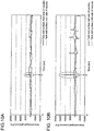
- FIGs. 10A and 10B are charts of analysis results, with respect to time, of an area-averaged pressure caused by sloshing of the oil and applied to a wall surface of an inner wall of the nacelle when the oil tank is arranged so that the longitudinal direction of the oil tank is along the horizontal direction orthogonal to a rotational axis of a rotation shaft of a wind turbine rotor in a floating wind turbine generator.
- Fig. 10A illustrates the area-averaged pressure applied to the wall surface of inner wall at the front side of the nacelle by a solid line, and the area-averaged pressure applied to the wall surface of the inner wall at the rear side of the nacelle by a dotted line.
- Fig. 10A illustrates the area-averaged pressure applied to the wall surface of inner wall at the front side of the nacelle by a solid line, and the area-averaged pressure applied to the wall surface of the inner wall at the rear side of the nacelle by a dotted line.
- FIG. 10B illustrates the area-averaged pressure applied to the wall surface of the inner wall at the left side of the nacelle by a solid line, and the area-averaged pressure applied to the wall surface of the inner wall at the right side of the nacelle by a dotted line.
- the partition wall 52 is arranged so that the wall surface 52a of the partition wall 52 extends along the front-rear direction of the nacelle, which is the rotational axis direction of the rotation shaft 12 of the wind turbine rotor 2. In this way, it is possible to effectively reduce sloshing caused by the sway in the rolling direction for the floating wind turbine generator 100.
- the oil tank 28 is configured to satisfy one of the following conditional expressions (A) or (B), and one of the following conditional expressions (C) or (D).
- gtanh ⁇ F max / L 1 4 ⁇ L 1 ⁇ f tower gtanh ⁇ F min / L 1 4 ⁇ L 1 > f tower
- gtanh ⁇ F max / L 2 4 ⁇ L 2 ⁇ f tower gtanh ⁇ F min / L 2 4 ⁇ L 2 > f tower
- the natural period T of sloshing of a tank is as follows: 4 ⁇ L gtanh ⁇ F / L
- L is the effective length of a tank (a length in a direction perpendicular to a partition wall of each oil chamber when the tank is partitioned into a plurality of oil chambers by one or more partition wall)
- F is the height of the oil surface in the oil tank.
- the sloshing frequency of each oil chamber varies depending on the height F of the oil surface in the oil tank.
- the oil tank 28 is configured to satisfy one of the following conditional expressions (E) or (F), and one of the following conditional expressions (G) or (H).
- E conditional expressions
- F conditional expressions
- G conditional expressions
- H conditional expressions
- f wave is a frequency of the significant wave applied to the floating body (typically, 0.05 to 0.2Hz).
- the oil tank 28 is configured to satisfy one of the following conditional expressions (I) or (J), and one of the following conditional expressions (K) or (L).
- f s is the natural frequency of sway in a direction perpendicular to the wall surface of the partition wall 52 in the floating wind turbine generator (typically, 0.03 to 0.05 Hz).
- the wall surface of the partition wall 52 preferably extends in a direction along the front-rear direction of the nacelle.
- the natural frequency of sway in a direction perpendicular to the wall surface of the partition wall 52 in the floating wind turbine generator 100 equals to the natural frequency of the sway in the rolling direction in the floating wind turbine generator 100.
- the wall surface of the partition wall 52 preferably extends in a direction along the right-left direction of the nacelle.
- the natural frequency of the sway in a direction perpendicular to the wall surface of the partition wall 52 in the floating wind turbine generator 100 equals to the natural frequency of the sway in the pitch direction in the floating wind turbine generator 100.
- FIG. 11 is a perspective view of an oil-storing unit including the oil tank 28 according to some embodiments.
- the wind turbine generator 100 includes an oil storing unit 58 illustrated in FIG. 11 .
- the oil storing unit 58 includes the oil tank 28 and an oil pan 60 capable of reserving oil that has leaked from the oil tank 28. Thus, even in the event of oil leakage from the oil tank 28, it is possible to restrict dispersion of the leaked oil.
- the oil pan 60 further includes a perforated plate 62 disposed so as to partition the space inside the oil pan 60.
- the oil storing unit 58 may include a plurality of perforated plates arranged in a grid shape, as illustrated in FIG. 11 . In this way, sloshing of the oil inside the oil pan 60 is restricted, which makes it is possible to effectively restrict the oil from spreading out.
- the present invention is not limited to the above described embodiments, and includes modifications of the above embodiments and combinations of the above embodiments.
Landscapes
- Engineering & Computer Science (AREA)
- General Engineering & Computer Science (AREA)
- Mechanical Engineering (AREA)
- Life Sciences & Earth Sciences (AREA)
- Sustainable Development (AREA)
- Sustainable Energy (AREA)
- Chemical & Material Sciences (AREA)
- Combustion & Propulsion (AREA)
- Wind Motors (AREA)
Claims (12)
- Réservoir d'huile (28) pour un aérogénérateur (100), disposé dans une nacelle (7) supportée sur une tour (14) de l'aérogénérateur, pour stocker l'huile utilisée dans une unité d'utilisation d'huile (4) incluse dans l'aérogénérateur, dans lequel le réservoir d'huile (28) comprend au moins :une première chambre d'huile (48) et une deuxième chambre d'huile (50) pour stocker l'huile ;une paroi de séparation (52) qui sépare la première chambre d'huile (48) et la deuxième chambre d'huile (50) ; etun dispositif de chauffage d'huile (56) pour chauffer l'huile dans le réservoir d'huile (28),dans lequel la deuxième chambre d'huile (50) est configurée pour pouvoir être reliée à une conduite de fourniture d'huile pour fournir l'huile à l'unité d'utilisation d'huile (4),dans lequel la première chambre d'huile (48) est configurée pour pouvoir être reliée à une conduite de récupération d'huile pour récupérer l'huile de l'unité d'utilisation d'huile (4), etdans lequel la paroi de séparation (52) comprend au moins deux ouvertures (54a, 54b) à travers lesquelles la première chambre d'huile (48) est en communication avec la deuxième chambre d'huile (50) de sorte que l'huile puisse être déplacée entre la première chambre d'huile (48) et la deuxième chambre d'huile (50),dans lequel lesdites au moins deux ouvertures comprennent une première ouverture (54a) et une deuxième ouverture (54b) qui est disposée au-dessous de la première ouverture (54a),dans lequel le dispositif de chauffage d'huile (56) est disposé dans la première chambre d'huile (48) ou dans la deuxième chambre d'huile (50), caractérisé en ce queune position d'extrémité inférieure (P) de la deuxième ouverture (54b) est au-dessus d'une position d'extrémité inférieure (Q) du dispositif de chauffage d'huile (56).
- Réservoir d'huile (28) pour un aérogénérateur selon la revendication 1,
dans lequel la deuxième ouverture (54b) est formée à une position où au moins une partie de la deuxième ouverture (54b) est superposée au dispositif de chauffage d'huile (56) tel que vu à partir d'une direction perpendiculaire à une surface de paroi de la paroi de séparation (52). - Réservoir d'huile (28) pour un aérogénérateur selon la revendication 1 ou 2,
dans lequel une position d'extrémité supérieure (R) de la première ouverture (54a) est au-dessous d'une hauteur possible minimum (Fmin) d'une surface d'huile dans le réservoir d'huile (28) pendant le fonctionnement de l'unité d'utilisation d'huile (4). - Réservoir d'huile (28) pour un aérogénérateur selon l'une quelconque des revendications 1 à 3,
dans lequel l'aérogénérateur est installé sur un corps flottant (18), dans lequel le réservoir d'huile (28) est agencé de sorte qu'une direction longitudinale du réservoir d'huile (28) soit le long d'une direction horizontale orthogonale à un axe de rotation d'un arbre rotatif (12) d'un rotor d'éolienne (2) inclus dans l'aérogénérateur, et
dans lequel la paroi de séparation (52) est agencée de sorte que la surface de paroi de la paroi de séparation (52) s'étende dans une direction de l'axe de rotation de l'arbre rotatif (12) du rotor d'éolienne (2) inclus dans l'aérogénérateur. - Réservoir d'huile (28) pour un aérogénérateur selon l'une quelconque des revendications 1 à 4,
dans lequel le réservoir d'huile (28) est configuré pour satisfaire à l'une des expressions conditionnelles (A) ou (B) suivantes, et à l'une des expressions conditionnelles (C) ou (D) suivantes :


 g est une accélération de gravité ;L1 est une longueur de la première chambre d'huile (48) dans la direction perpendiculaire à la surface de paroi de la paroi de séparation (52) ;L2 est une longueur de la deuxième chambre d'huile (50) dans la direction perpendiculaire à la surface de paroi de la paroi de séparation (52) ;fmax est une hauteur possible maximum de la surface d'huile dans le réservoir d'huile (28) alors que l'unité d'utilisation d'huile (4) n'est pas en fonctionnement ;fmin est une hauteur possible minimum de la surface d'huile dans le réservoir d'huile (28) pendant le fonctionnement de l'unité d'utilisation d'huile (4) ; etftower est une fréquence naturelle d'un mode de flexion de l'aérogénérateur complet.
 - Réservoir d'huile (28) pour un aérogénérateur selon l'une quelconque des revendications 1 à 5,
dans lequel l'aérogénérateur est installé sur un corps flottant (18), et
dans lequel le réservoir d'huile (28) est configuré pour satisfaire à l'une des expressions conditionnelles (E) ou (F) suivantes, et à l'une des expressions conditionnelles (G) ou (H) suivantes :


 g est une accélération de gravité ;L1 est une longueur de la première chambre d'huile (48) dans la direction perpendiculaire à la surface de paroi de la paroi de séparation (52) ;L2 est une longueur de la deuxième chambre d'huile (50) dans la direction perpendiculaire à la surface de paroi de la paroi de séparation (52) ;fmax est une hauteur possible maximum de la surface d'huile dans le réservoir d'huile (28) alors que l'unité d'utilisation d'huile (4) n'est pas en fonctionnement ;fmin est une hauteur possible minimum de la surface d'huile dans le réservoir d'huile (28) pendant le fonctionnement de l'unité d'utilisation d'huile (4) ; etfwave est une fréquence d'une onde significative appliquée au corps flottant (18).
 - Réservoir d'huile (28) pour un aérogénérateur selon l'une quelconque des revendications 1 à 6,
dans lequel l'aérogénérateur est installé sur un corps flottant (18), et
dans lequel le réservoir d'huile (28) est configuré pour satisfaire à l'une des expressions conditionnelles (I) ou (J) suivantes, et à l'une des expressions conditionnelles (K) ou (L) suivantes :


 g est une accélération de gravité ;L1 est une longueur de la première chambre d'huile (48) dans la direction perpendiculaire à la surface de paroi de la paroi de séparation (52) ;L2 est une longueur de la deuxième chambre d'huile (50) dans la direction perpendiculaire à la surface de paroi de la paroi de séparation (52) ;fmax est une hauteur possible maximum de la surface d'huile dans le réservoir d'huile (28) alors que l'unité d'utilisation d'huile (4) n'est pas en fonctionnement ;fmin est une hauteur possible minimum de la surface d'huile dans le réservoir d'huile (28) pendant le fonctionnement de l'unité d'utilisation d'huile (4) ; etfs est une fréquence naturelle de balancement dans la direction perpendiculaire à la surface de paroi de la paroi de séparation dans l'aérogénérateur installé sur le corps flottant (18).
 - Réservoir d'huile (28) pour un aérogénérateur selon l'une quelconque des revendications 1 à 7,
dans lequel le réservoir d'huile (28) a une forme cuboïde ou une forme cubique, et
dans lequel la paroi de séparation (52) est agencée de sorte que la première chambre d'huile (48) et la deuxième chambre d'huile (50) aient chacune une forme cuboïde ou une forme cubique. - Réservoir d'huile (28) pour un aérogénérateur selon l'une quelconque des revendications 1 à 8,
dans lequel l'intérieur du réservoir d'huile (28) est en communication avec l'air atmosphérique de sorte qu'une pression à l'intérieur du réservoir d'huile (28) soit une pression atmosphérique. - Unité de stockage d'huile (4) pour un aérogénérateur, comprenant :le réservoir d'huile (28) selon l'une quelconque des revendications 1 à 9, etun carter d'huile (60) capable de stocker l'huile qui a fui du réservoir d'huile (28).
- Unité de stockage d'huile pour un aérogénérateur selon la revendication 10,
dans laquelle le carter d'huile (60) comprend en outre une plaque perforée (62) disposée de manière à diviser un espace à l'intérieur du carter d'huile. - Aérogénérateur (100) comprenant :le réservoir d'huile (28) selon l'une quelconque des revendications 1 à9;une unité d'utilisation d'huile (4) utilisant l'huile dans le réservoir d'huile (28) ;un rotor d'éolienne (2) comprenant au moins une pale d'éolienne (8) ;un générateur (6) configuré pour être entraîné lors de la réception de l'énergie de rotation du rotor d'éolienne (2) ;une nacelle (7) pour loger le réservoir d'huile (28), l'unité d'utilisation d'huile (4), et le générateur (6) ; etune tour (14) supportant la nacelle (7).
Applications Claiming Priority (1)
| Application Number | Priority Date | Filing Date | Title |
|---|---|---|---|
| JP2014108648A JP6208625B2 (ja) | 2014-05-27 | 2014-05-27 | 風力発電装置用オイルタンク、オイル収容ユニット及び風力発電装置 |
Publications (2)
| Publication Number | Publication Date |
|---|---|
| EP2949986A1 EP2949986A1 (fr) | 2015-12-02 |
| EP2949986B1 true EP2949986B1 (fr) | 2017-08-02 |
Family
ID=52577760
Family Applications (1)
| Application Number | Title | Priority Date | Filing Date |
|---|---|---|---|
| EP15156772.4A Not-in-force EP2949986B1 (fr) | 2014-05-27 | 2015-02-26 | Réservoir d'huile pour générateur de turbine éolienne, unité de stockage de l'huile et générateur de turbine éolienne |
Country Status (2)
| Country | Link |
|---|---|
| EP (1) | EP2949986B1 (fr) |
| JP (1) | JP6208625B2 (fr) |
Cited By (1)
| Publication number | Priority date | Publication date | Assignee | Title |
|---|---|---|---|---|
| EP4177462A1 (fr) * | 2021-11-09 | 2023-05-10 | Terawind GmbH | Dispositif de conversion de l'énergie éolienne en énergie électrique |
Families Citing this family (6)
| Publication number | Priority date | Publication date | Assignee | Title |
|---|---|---|---|---|
| EP3372823A1 (fr) * | 2017-03-07 | 2018-09-12 | Adwen GmbH | Nacelle comportant des composants multifonctionnels |
| EP3372825A1 (fr) * | 2017-03-07 | 2018-09-12 | Adwen GmbH | Nacelle possédant des propriétés de rétention de liquide |
| CN107299871B (zh) * | 2017-04-19 | 2023-03-14 | 内蒙古科技大学 | 一种利用回收车载油箱中油液晃动能量的节油装置 |
| CN114901944B (zh) * | 2020-01-08 | 2025-04-29 | 维斯塔斯风力系统有限公司 | 风力涡轮机的主轴承壳体 |
| US12049873B2 (en) * | 2020-01-08 | 2024-07-30 | Vestas Wind Systems A/S | Main bearing housing of a wind turbine |
| CN112412704A (zh) * | 2020-11-20 | 2021-02-26 | 田剑辉 | 一种电力设备用具有节能容电功能的发电风车 |
Family Cites Families (11)
| Publication number | Priority date | Publication date | Assignee | Title |
|---|---|---|---|---|
| JP2872914B2 (ja) * | 1994-08-25 | 1999-03-24 | 株式会社日立製作所 | 歯車変速機 |
| US5611411A (en) * | 1996-05-10 | 1997-03-18 | Florida Power Corporation | Turbine lubrication oil filtration safeguard system |
| JP2003176774A (ja) * | 2001-12-10 | 2003-06-27 | Kyowa Engineering Consultants Co Ltd | 風力発電装置 |
| ATE471462T1 (de) * | 2002-04-24 | 2010-07-15 | Vestas Wind Sys As | Windturbine, hydrauliksystem, entlüftungssystem und verfahren zur steuerung mindestens zweier windturbinenschaufeln |
| JP2007107409A (ja) * | 2005-10-12 | 2007-04-26 | Yanmar Co Ltd | 風力発電装置 |
| ES2396138T3 (es) * | 2008-06-02 | 2013-02-19 | Vestas Wind Systems A/S | Un sistema de lubricación para un sistema de engranajes para una turbina eólica |
| ES2442176T3 (es) * | 2009-10-23 | 2014-02-10 | Vestas Wind Systems A/S | Sistema de lubricación para un sistema de engranaje de una turbina eólica que proporciona lubricación de emergencia |
| BRPI1001243A2 (pt) * | 2010-02-08 | 2016-02-16 | Mitsubishi Heavy Ind Ltd | mecanismo de aquecimento de lubrificante, mecanismo de engrenagem, e, gerador de turbina eólica |
| DE102011008672A1 (de) | 2011-01-15 | 2012-07-19 | Hydac Filtertechnik Gmbh | Vorrichtung zum Schmieren eines Getriebes sowie eines Lagers |
| DE102011080359A1 (de) * | 2011-05-31 | 2012-12-06 | Siemens Aktiengesellschaft | Windturbinengetriebe |
| ES2396813B1 (es) * | 2011-06-28 | 2014-01-17 | Gamesa Innovation & Technology, S.L. | Sistema de mantenimiento de nivel de aceite. |
-
2014
- 2014-05-27 JP JP2014108648A patent/JP6208625B2/ja not_active Expired - Fee Related
-
2015
- 2015-02-26 EP EP15156772.4A patent/EP2949986B1/fr not_active Not-in-force
Non-Patent Citations (1)
| Title |
|---|
| None * |
Cited By (2)
| Publication number | Priority date | Publication date | Assignee | Title |
|---|---|---|---|---|
| EP4177462A1 (fr) * | 2021-11-09 | 2023-05-10 | Terawind GmbH | Dispositif de conversion de l'énergie éolienne en énergie électrique |
| WO2023083597A1 (fr) * | 2021-11-09 | 2023-05-19 | Terawind Gmbh | Appareil de conversion d'énergie éolienne en énergie électrique |
Also Published As
| Publication number | Publication date |
|---|---|
| EP2949986A1 (fr) | 2015-12-02 |
| JP2015224566A (ja) | 2015-12-14 |
| JP6208625B2 (ja) | 2017-10-04 |
Similar Documents
| Publication | Publication Date | Title |
|---|---|---|
| EP2949986A1 (fr) | Réservoir d'huile pour générateur de turbine éolienne, unité de stockage de l'huile et générateur de turbine éolienne | |
| US9022174B2 (en) | Lubrication device of power transmission device for hybrid vehicle | |
| EP2988001A1 (fr) | Appareil de génération d'énergie renouvelable et procédé d'exploitation dudit système | |
| NO310084B1 (no) | Fundamentramme for en gassturbin | |
| US20120006137A1 (en) | Gear driven accessory for gearbox | |
| EP4088025B1 (fr) | Logement de palier principal d'une éolienne | |
| CN102232161A (zh) | 润滑油加热机构、齿轮机构、以及风力发电装置 | |
| KR20130109227A (ko) | 풍력 발전 설비 | |
| DE102018125551A1 (de) | Fluidschleifenfüllbaugruppe und füllverfahren | |
| ITRM20110581A1 (it) | Dispositivo di conversione dell'energia meccanica delle onde del mare in energia elettrica | |
| EP3615797B1 (fr) | Nacelle d'éolienne avec système de fluide embarqué | |
| JP2015224566A5 (fr) | ||
| CN108026941A (zh) | 发电系统的工作油罐及工作油向该工作油罐的封入方法 | |
| US20140348641A1 (en) | Low-drag hydro-pneumatic power cylinder and system | |
| EP2435691B1 (fr) | Installation de conversion d'énergie pour la conversion de l'énergie des vagues | |
| KR20150088797A (ko) | 부유하는 해류 터빈 | |
| US20160298594A1 (en) | Mechanical leverage and gravity generating clean power plant | |
| CN102705494B (zh) | 行星齿轮副的自润滑装置 | |
| GB2511272A (en) | A wind turbine | |
| JP2022521742A (ja) | 水力発電装置 | |
| KR20130128561A (ko) | 양방향 구동력을 전달받는 선박 엔진용 폐열회수장치 | |
| EP4088024B1 (fr) | Logement principal de paliers d'une éolienne | |
| KR20200140227A (ko) | 해수 양수장치 | |
| RU2536462C1 (ru) | Установка для преобразования энергии качки плавающего судна | |
| CN216199334U (zh) | 一种带有防护结构的液压油箱 |
Legal Events
| Date | Code | Title | Description |
|---|---|---|---|
| AK | Designated contracting states |
Kind code of ref document: A1 Designated state(s): AL AT BE BG CH CY CZ DE DK EE ES FI FR GB GR HR HU IE IS IT LI LT LU LV MC MK MT NL NO PL PT RO RS SE SI SK SM TR |
|
| AX | Request for extension of the european patent |
Extension state: BA ME |
|
| PUAI | Public reference made under article 153(3) epc to a published international application that has entered the european phase |
Free format text: ORIGINAL CODE: 0009012 |
|
| 17P | Request for examination filed |
Effective date: 20160314 |
|
| RBV | Designated contracting states (corrected) |
Designated state(s): AL AT BE BG CH CY CZ DE DK EE ES FI FR GB GR HR HU IE IS IT LI LT LU LV MC MK MT NL NO PL PT RO RS SE SI SK SM TR |
|
| 17Q | First examination report despatched |
Effective date: 20160628 |
|
| REG | Reference to a national code |
Ref country code: DE Ref legal event code: R079 Ref document number: 602015003804 Country of ref document: DE Free format text: PREVIOUS MAIN CLASS: F16N0039040000 Ipc: F03D0080000000 |
|
| GRAP | Despatch of communication of intention to grant a patent |
Free format text: ORIGINAL CODE: EPIDOSNIGR1 |
|
| RIC1 | Information provided on ipc code assigned before grant |
Ipc: F16N 39/04 20060101ALI20170113BHEP Ipc: F03D 80/00 20160101AFI20170113BHEP |
|
| INTG | Intention to grant announced |
Effective date: 20170206 |
|
| GRAS | Grant fee paid |
Free format text: ORIGINAL CODE: EPIDOSNIGR3 |
|
| GRAJ | Information related to disapproval of communication of intention to grant by the applicant or resumption of examination proceedings by the epo deleted |
Free format text: ORIGINAL CODE: EPIDOSDIGR1 |
|
| GRAL | Information related to payment of fee for publishing/printing deleted |
Free format text: ORIGINAL CODE: EPIDOSDIGR3 |
|
| GRAP | Despatch of communication of intention to grant a patent |
Free format text: ORIGINAL CODE: EPIDOSNIGR1 |
|
| INTC | Intention to grant announced (deleted) | ||
| GRAA | (expected) grant |
Free format text: ORIGINAL CODE: 0009210 |
|
| INTG | Intention to grant announced |
Effective date: 20170609 |
|
| AK | Designated contracting states |
Kind code of ref document: B1 Designated state(s): AL AT BE BG CH CY CZ DE DK EE ES FI FR GB GR HR HU IE IS IT LI LT LU LV MC MK MT NL NO PL PT RO RS SE SI SK SM TR |
|
| REG | Reference to a national code |
Ref country code: CH Ref legal event code: EP Ref country code: AT Ref legal event code: REF Ref document number: 914790 Country of ref document: AT Kind code of ref document: T Effective date: 20170815 |
|
| REG | Reference to a national code |
Ref country code: IE Ref legal event code: FG4D |
|
| REG | Reference to a national code |
Ref country code: DE Ref legal event code: R096 Ref document number: 602015003804 Country of ref document: DE |
|
| REG | Reference to a national code |
Ref country code: NL Ref legal event code: MP Effective date: 20170802 |
|
| REG | Reference to a national code |
Ref country code: AT Ref legal event code: MK05 Ref document number: 914790 Country of ref document: AT Kind code of ref document: T Effective date: 20170802 |
|
| REG | Reference to a national code |
Ref country code: LT Ref legal event code: MG4D |
|
| PG25 | Lapsed in a contracting state [announced via postgrant information from national office to epo] |
Ref country code: NL Free format text: LAPSE BECAUSE OF FAILURE TO SUBMIT A TRANSLATION OF THE DESCRIPTION OR TO PAY THE FEE WITHIN THE PRESCRIBED TIME-LIMIT Effective date: 20170802 Ref country code: NO Free format text: LAPSE BECAUSE OF FAILURE TO SUBMIT A TRANSLATION OF THE DESCRIPTION OR TO PAY THE FEE WITHIN THE PRESCRIBED TIME-LIMIT Effective date: 20171102 Ref country code: SE Free format text: LAPSE BECAUSE OF FAILURE TO SUBMIT A TRANSLATION OF THE DESCRIPTION OR TO PAY THE FEE WITHIN THE PRESCRIBED TIME-LIMIT Effective date: 20170802 Ref country code: HR Free format text: LAPSE BECAUSE OF FAILURE TO SUBMIT A TRANSLATION OF THE DESCRIPTION OR TO PAY THE FEE WITHIN THE PRESCRIBED TIME-LIMIT Effective date: 20170802 Ref country code: FI Free format text: LAPSE BECAUSE OF FAILURE TO SUBMIT A TRANSLATION OF THE DESCRIPTION OR TO PAY THE FEE WITHIN THE PRESCRIBED TIME-LIMIT Effective date: 20170802 Ref country code: AT Free format text: LAPSE BECAUSE OF FAILURE TO SUBMIT A TRANSLATION OF THE DESCRIPTION OR TO PAY THE FEE WITHIN THE PRESCRIBED TIME-LIMIT Effective date: 20170802 Ref country code: LT Free format text: LAPSE BECAUSE OF FAILURE TO SUBMIT A TRANSLATION OF THE DESCRIPTION OR TO PAY THE FEE WITHIN THE PRESCRIBED TIME-LIMIT Effective date: 20170802 |
|
| REG | Reference to a national code |
Ref country code: FR Ref legal event code: PLFP Year of fee payment: 4 |
|
| PG25 | Lapsed in a contracting state [announced via postgrant information from national office to epo] |
Ref country code: PL Free format text: LAPSE BECAUSE OF FAILURE TO SUBMIT A TRANSLATION OF THE DESCRIPTION OR TO PAY THE FEE WITHIN THE PRESCRIBED TIME-LIMIT Effective date: 20170802 Ref country code: RS Free format text: LAPSE BECAUSE OF FAILURE TO SUBMIT A TRANSLATION OF THE DESCRIPTION OR TO PAY THE FEE WITHIN THE PRESCRIBED TIME-LIMIT Effective date: 20170802 Ref country code: BG Free format text: LAPSE BECAUSE OF FAILURE TO SUBMIT A TRANSLATION OF THE DESCRIPTION OR TO PAY THE FEE WITHIN THE PRESCRIBED TIME-LIMIT Effective date: 20171102 Ref country code: IS Free format text: LAPSE BECAUSE OF FAILURE TO SUBMIT A TRANSLATION OF THE DESCRIPTION OR TO PAY THE FEE WITHIN THE PRESCRIBED TIME-LIMIT Effective date: 20171202 Ref country code: ES Free format text: LAPSE BECAUSE OF FAILURE TO SUBMIT A TRANSLATION OF THE DESCRIPTION OR TO PAY THE FEE WITHIN THE PRESCRIBED TIME-LIMIT Effective date: 20170802 Ref country code: GR Free format text: LAPSE BECAUSE OF FAILURE TO SUBMIT A TRANSLATION OF THE DESCRIPTION OR TO PAY THE FEE WITHIN THE PRESCRIBED TIME-LIMIT Effective date: 20171103 Ref country code: LV Free format text: LAPSE BECAUSE OF FAILURE TO SUBMIT A TRANSLATION OF THE DESCRIPTION OR TO PAY THE FEE WITHIN THE PRESCRIBED TIME-LIMIT Effective date: 20170802 |
|
| PG25 | Lapsed in a contracting state [announced via postgrant information from national office to epo] |
Ref country code: CZ Free format text: LAPSE BECAUSE OF FAILURE TO SUBMIT A TRANSLATION OF THE DESCRIPTION OR TO PAY THE FEE WITHIN THE PRESCRIBED TIME-LIMIT Effective date: 20170802 Ref country code: DK Free format text: LAPSE BECAUSE OF FAILURE TO SUBMIT A TRANSLATION OF THE DESCRIPTION OR TO PAY THE FEE WITHIN THE PRESCRIBED TIME-LIMIT Effective date: 20170802 Ref country code: RO Free format text: LAPSE BECAUSE OF FAILURE TO SUBMIT A TRANSLATION OF THE DESCRIPTION OR TO PAY THE FEE WITHIN THE PRESCRIBED TIME-LIMIT Effective date: 20170802 |
|
| REG | Reference to a national code |
Ref country code: DE Ref legal event code: R097 Ref document number: 602015003804 Country of ref document: DE |
|
| PG25 | Lapsed in a contracting state [announced via postgrant information from national office to epo] |
Ref country code: SM Free format text: LAPSE BECAUSE OF FAILURE TO SUBMIT A TRANSLATION OF THE DESCRIPTION OR TO PAY THE FEE WITHIN THE PRESCRIBED TIME-LIMIT Effective date: 20170802 Ref country code: IT Free format text: LAPSE BECAUSE OF FAILURE TO SUBMIT A TRANSLATION OF THE DESCRIPTION OR TO PAY THE FEE WITHIN THE PRESCRIBED TIME-LIMIT Effective date: 20170802 Ref country code: SK Free format text: LAPSE BECAUSE OF FAILURE TO SUBMIT A TRANSLATION OF THE DESCRIPTION OR TO PAY THE FEE WITHIN THE PRESCRIBED TIME-LIMIT Effective date: 20170802 Ref country code: EE Free format text: LAPSE BECAUSE OF FAILURE TO SUBMIT A TRANSLATION OF THE DESCRIPTION OR TO PAY THE FEE WITHIN THE PRESCRIBED TIME-LIMIT Effective date: 20170802 |
|
| PLBE | No opposition filed within time limit |
Free format text: ORIGINAL CODE: 0009261 |
|
| STAA | Information on the status of an ep patent application or granted ep patent |
Free format text: STATUS: NO OPPOSITION FILED WITHIN TIME LIMIT |
|
| 26N | No opposition filed |
Effective date: 20180503 |
|
| PG25 | Lapsed in a contracting state [announced via postgrant information from national office to epo] |
Ref country code: SI Free format text: LAPSE BECAUSE OF FAILURE TO SUBMIT A TRANSLATION OF THE DESCRIPTION OR TO PAY THE FEE WITHIN THE PRESCRIBED TIME-LIMIT Effective date: 20170802 |
|
| REG | Reference to a national code |
Ref country code: CH Ref legal event code: PL |
|
| PG25 | Lapsed in a contracting state [announced via postgrant information from national office to epo] |
Ref country code: MC Free format text: LAPSE BECAUSE OF FAILURE TO SUBMIT A TRANSLATION OF THE DESCRIPTION OR TO PAY THE FEE WITHIN THE PRESCRIBED TIME-LIMIT Effective date: 20170802 |
|
| REG | Reference to a national code |
Ref country code: IE Ref legal event code: MM4A |
|
| REG | Reference to a national code |
Ref country code: BE Ref legal event code: MM Effective date: 20180228 |
|
| PG25 | Lapsed in a contracting state [announced via postgrant information from national office to epo] |
Ref country code: LU Free format text: LAPSE BECAUSE OF NON-PAYMENT OF DUE FEES Effective date: 20180226 Ref country code: LI Free format text: LAPSE BECAUSE OF NON-PAYMENT OF DUE FEES Effective date: 20180228 Ref country code: CH Free format text: LAPSE BECAUSE OF NON-PAYMENT OF DUE FEES Effective date: 20180228 |
|
| PG25 | Lapsed in a contracting state [announced via postgrant information from national office to epo] |
Ref country code: IE Free format text: LAPSE BECAUSE OF NON-PAYMENT OF DUE FEES Effective date: 20180226 |
|
| PG25 | Lapsed in a contracting state [announced via postgrant information from national office to epo] |
Ref country code: BE Free format text: LAPSE BECAUSE OF NON-PAYMENT OF DUE FEES Effective date: 20180228 |
|
| PGFP | Annual fee paid to national office [announced via postgrant information from national office to epo] |
Ref country code: FR Payment date: 20190111 Year of fee payment: 5 Ref country code: GB Payment date: 20190220 Year of fee payment: 5 Ref country code: DE Payment date: 20190212 Year of fee payment: 5 |
|
| PG25 | Lapsed in a contracting state [announced via postgrant information from national office to epo] |
Ref country code: MT Free format text: LAPSE BECAUSE OF NON-PAYMENT OF DUE FEES Effective date: 20180226 |
|
| PG25 | Lapsed in a contracting state [announced via postgrant information from national office to epo] |
Ref country code: TR Free format text: LAPSE BECAUSE OF FAILURE TO SUBMIT A TRANSLATION OF THE DESCRIPTION OR TO PAY THE FEE WITHIN THE PRESCRIBED TIME-LIMIT Effective date: 20170802 |
|
| PG25 | Lapsed in a contracting state [announced via postgrant information from national office to epo] |
Ref country code: PT Free format text: LAPSE BECAUSE OF FAILURE TO SUBMIT A TRANSLATION OF THE DESCRIPTION OR TO PAY THE FEE WITHIN THE PRESCRIBED TIME-LIMIT Effective date: 20170802 |
|
| PG25 | Lapsed in a contracting state [announced via postgrant information from national office to epo] |
Ref country code: CY Free format text: LAPSE BECAUSE OF FAILURE TO SUBMIT A TRANSLATION OF THE DESCRIPTION OR TO PAY THE FEE WITHIN THE PRESCRIBED TIME-LIMIT Effective date: 20170802 Ref country code: HU Free format text: LAPSE BECAUSE OF FAILURE TO SUBMIT A TRANSLATION OF THE DESCRIPTION OR TO PAY THE FEE WITHIN THE PRESCRIBED TIME-LIMIT; INVALID AB INITIO Effective date: 20150226 Ref country code: MK Free format text: LAPSE BECAUSE OF NON-PAYMENT OF DUE FEES Effective date: 20170802 |
|
| PG25 | Lapsed in a contracting state [announced via postgrant information from national office to epo] |
Ref country code: AL Free format text: LAPSE BECAUSE OF FAILURE TO SUBMIT A TRANSLATION OF THE DESCRIPTION OR TO PAY THE FEE WITHIN THE PRESCRIBED TIME-LIMIT Effective date: 20170802 |
|
| REG | Reference to a national code |
Ref country code: DE Ref legal event code: R119 Ref document number: 602015003804 Country of ref document: DE |
|
| GBPC | Gb: european patent ceased through non-payment of renewal fee |
Effective date: 20200226 |
|
| PG25 | Lapsed in a contracting state [announced via postgrant information from national office to epo] |
Ref country code: DE Free format text: LAPSE BECAUSE OF NON-PAYMENT OF DUE FEES Effective date: 20200901 Ref country code: FR Free format text: LAPSE BECAUSE OF NON-PAYMENT OF DUE FEES Effective date: 20200229 Ref country code: GB Free format text: LAPSE BECAUSE OF NON-PAYMENT OF DUE FEES Effective date: 20200226 |