EP2949937B1 - Convertisseur - Google Patents
Convertisseur Download PDFInfo
- Publication number
- EP2949937B1 EP2949937B1 EP14170314.0A EP14170314A EP2949937B1 EP 2949937 B1 EP2949937 B1 EP 2949937B1 EP 14170314 A EP14170314 A EP 14170314A EP 2949937 B1 EP2949937 B1 EP 2949937B1
- Authority
- EP
- European Patent Office
- Prior art keywords
- convertor
- accordance
- members
- movement
- actuator
- Prior art date
- Legal status (The legal status is an assumption and is not a legal conclusion. Google has not performed a legal analysis and makes no representation as to the accuracy of the status listed.)
- Not-in-force
Links
- 239000000463 material Substances 0.000 claims description 50
- 241000256247 Spodoptera exigua Species 0.000 claims description 8
- 238000000576 coating method Methods 0.000 claims description 8
- 239000011248 coating agent Substances 0.000 claims description 7
- 230000000694 effects Effects 0.000 claims description 7
- 238000007689 inspection Methods 0.000 claims description 7
- 229910052751 metal Inorganic materials 0.000 claims description 6
- 239000002184 metal Substances 0.000 claims description 6
- 238000003466 welding Methods 0.000 claims description 6
- 238000004140 cleaning Methods 0.000 claims description 4
- 230000008602 contraction Effects 0.000 claims description 4
- 230000001747 exhibiting effect Effects 0.000 claims description 4
- 230000002572 peristaltic effect Effects 0.000 claims description 4
- 230000002708 enhancing effect Effects 0.000 claims description 3
- 239000004033 plastic Substances 0.000 claims description 3
- 239000005060 rubber Substances 0.000 claims description 3
- 206010073306 Exposure to radiation Diseases 0.000 claims description 2
- 210000004204 blood vessel Anatomy 0.000 claims description 2
- 239000000919 ceramic Substances 0.000 claims description 2
- 230000009194 climbing Effects 0.000 claims description 2
- 238000002485 combustion reaction Methods 0.000 claims description 2
- 125000004122 cyclic group Chemical group 0.000 claims description 2
- 239000006260 foam Substances 0.000 claims description 2
- 239000007788 liquid Substances 0.000 claims description 2
- 230000003534 oscillatory effect Effects 0.000 claims description 2
- 229920000642 polymer Polymers 0.000 claims description 2
- 239000000126 substance Substances 0.000 claims description 2
- 230000006835 compression Effects 0.000 description 4
- 238000007906 compression Methods 0.000 description 4
- 230000007246 mechanism Effects 0.000 description 4
- 241000282887 Suidae Species 0.000 description 3
- 239000002131 composite material Substances 0.000 description 3
- 210000000080 chela (arthropods) Anatomy 0.000 description 2
- 239000012530 fluid Substances 0.000 description 2
- VNWKTOKETHGBQD-UHFFFAOYSA-N methane Chemical compound C VNWKTOKETHGBQD-UHFFFAOYSA-N 0.000 description 2
- 230000009467 reduction Effects 0.000 description 2
- 239000011359 shock absorbing material Substances 0.000 description 2
- 238000005299 abrasion Methods 0.000 description 1
- 230000004913 activation Effects 0.000 description 1
- 239000004411 aluminium Substances 0.000 description 1
- 229910052782 aluminium Inorganic materials 0.000 description 1
- XAGFODPZIPBFFR-UHFFFAOYSA-N aluminium Chemical compound [Al] XAGFODPZIPBFFR-UHFFFAOYSA-N 0.000 description 1
- 230000000295 complement effect Effects 0.000 description 1
- 238000010276 construction Methods 0.000 description 1
- 239000010779 crude oil Substances 0.000 description 1
- 239000013078 crystal Substances 0.000 description 1
- 230000007423 decrease Effects 0.000 description 1
- 230000005489 elastic deformation Effects 0.000 description 1
- 239000011521 glass Substances 0.000 description 1
- 210000003127 knee Anatomy 0.000 description 1
- 238000005461 lubrication Methods 0.000 description 1
- 238000012423 maintenance Methods 0.000 description 1
- 238000004519 manufacturing process Methods 0.000 description 1
- 150000002739 metals Chemical class 0.000 description 1
- 239000003345 natural gas Substances 0.000 description 1
- 239000003921 oil Substances 0.000 description 1
- 238000012856 packing Methods 0.000 description 1
- 230000002040 relaxant effect Effects 0.000 description 1
- 230000008439 repair process Effects 0.000 description 1
- 241000894007 species Species 0.000 description 1
- 239000007921 spray Substances 0.000 description 1
- 229910001220 stainless steel Inorganic materials 0.000 description 1
- 239000010935 stainless steel Substances 0.000 description 1
- 238000005406 washing Methods 0.000 description 1
Images


Classifications
-
- F—MECHANICAL ENGINEERING; LIGHTING; HEATING; WEAPONS; BLASTING
- F03—MACHINES OR ENGINES FOR LIQUIDS; WIND, SPRING, OR WEIGHT MOTORS; PRODUCING MECHANICAL POWER OR A REACTIVE PROPULSIVE THRUST, NOT OTHERWISE PROVIDED FOR
- F03G—SPRING, WEIGHT, INERTIA OR LIKE MOTORS; MECHANICAL-POWER PRODUCING DEVICES OR MECHANISMS, NOT OTHERWISE PROVIDED FOR OR USING ENERGY SOURCES NOT OTHERWISE PROVIDED FOR
- F03G3/00—Other motors, e.g. gravity or inertia motors
-
- F—MECHANICAL ENGINEERING; LIGHTING; HEATING; WEAPONS; BLASTING
- F04—POSITIVE - DISPLACEMENT MACHINES FOR LIQUIDS; PUMPS FOR LIQUIDS OR ELASTIC FLUIDS
- F04B—POSITIVE-DISPLACEMENT MACHINES FOR LIQUIDS; PUMPS
- F04B43/00—Machines, pumps, or pumping installations having flexible working members
- F04B43/0009—Special features
- F04B43/0054—Special features particularities of the flexible members
-
- B—PERFORMING OPERATIONS; TRANSPORTING
- B08—CLEANING
- B08B—CLEANING IN GENERAL; PREVENTION OF FOULING IN GENERAL
- B08B9/00—Cleaning hollow articles by methods or apparatus specially adapted thereto
- B08B9/02—Cleaning pipes or tubes or systems of pipes or tubes
- B08B9/027—Cleaning the internal surfaces; Removal of blockages
- B08B9/04—Cleaning the internal surfaces; Removal of blockages using cleaning devices introduced into and moved along the pipes
- B08B9/049—Cleaning the internal surfaces; Removal of blockages using cleaning devices introduced into and moved along the pipes having self-contained propelling means for moving the cleaning devices along the pipes, i.e. self-propelled
-
- F—MECHANICAL ENGINEERING; LIGHTING; HEATING; WEAPONS; BLASTING
- F04—POSITIVE - DISPLACEMENT MACHINES FOR LIQUIDS; PUMPS FOR LIQUIDS OR ELASTIC FLUIDS
- F04B—POSITIVE-DISPLACEMENT MACHINES FOR LIQUIDS; PUMPS
- F04B43/00—Machines, pumps, or pumping installations having flexible working members
- F04B43/12—Machines, pumps, or pumping installations having flexible working members having peristaltic action
-
- F—MECHANICAL ENGINEERING; LIGHTING; HEATING; WEAPONS; BLASTING
- F16—ENGINEERING ELEMENTS AND UNITS; GENERAL MEASURES FOR PRODUCING AND MAINTAINING EFFECTIVE FUNCTIONING OF MACHINES OR INSTALLATIONS; THERMAL INSULATION IN GENERAL
- F16L—PIPES; JOINTS OR FITTINGS FOR PIPES; SUPPORTS FOR PIPES, CABLES OR PROTECTIVE TUBING; MEANS FOR THERMAL INSULATION IN GENERAL
- F16L55/00—Devices or appurtenances for use in, or in connection with, pipes or pipe systems
- F16L55/26—Pigs or moles, i.e. devices movable in a pipe or conduit with or without self-contained propulsion means
- F16L55/28—Constructional aspects
- F16L55/40—Constructional aspects of the body
-
- F—MECHANICAL ENGINEERING; LIGHTING; HEATING; WEAPONS; BLASTING
- F28—HEAT EXCHANGE IN GENERAL
- F28G—CLEANING OF INTERNAL OR EXTERNAL SURFACES OF HEAT-EXCHANGE OR HEAT-TRANSFER CONDUITS, e.g. WATER TUBES OR BOILERS
- F28G1/00—Non-rotary, e.g. reciprocated, appliances
- F28G1/12—Fluid-propelled scrapers, bullets, or like solid bodies
-
- F—MECHANICAL ENGINEERING; LIGHTING; HEATING; WEAPONS; BLASTING
- F16—ENGINEERING ELEMENTS AND UNITS; GENERAL MEASURES FOR PRODUCING AND MAINTAINING EFFECTIVE FUNCTIONING OF MACHINES OR INSTALLATIONS; THERMAL INSULATION IN GENERAL
- F16L—PIPES; JOINTS OR FITTINGS FOR PIPES; SUPPORTS FOR PIPES, CABLES OR PROTECTIVE TUBING; MEANS FOR THERMAL INSULATION IN GENERAL
- F16L2101/00—Uses or applications of pigs or moles
- F16L2101/30—Inspecting, measuring or testing
-
- Y—GENERAL TAGGING OF NEW TECHNOLOGICAL DEVELOPMENTS; GENERAL TAGGING OF CROSS-SECTIONAL TECHNOLOGIES SPANNING OVER SEVERAL SECTIONS OF THE IPC; TECHNICAL SUBJECTS COVERED BY FORMER USPC CROSS-REFERENCE ART COLLECTIONS [XRACs] AND DIGESTS
- Y10—TECHNICAL SUBJECTS COVERED BY FORMER USPC
- Y10T—TECHNICAL SUBJECTS COVERED BY FORMER US CLASSIFICATION
- Y10T74/00—Machine element or mechanism
- Y10T74/15—Intermittent grip type mechanical movement
- Y10T74/1526—Oscillation or reciprocation to intermittent unidirectional motion
Definitions
- the present invention relates to a convertor for converting alternating movement to unidirectional movement.
- Convertors of this kind are actually relatively rare and mainly in the form of peristaltic pumps and so-called, inchworm motors.
- Peristaltic pumps however actually produce unidirectional movement of a fluid, and are arranged at a fixed position and thus do not themselves move.
- Pipeline pigs are designed for introduction into e.g. a natural gas or an oil pipeline, in order to clean residues from the inside of the pipeline.
- Some pipeline pigs are drawn by cables, some are pushed along a pipeline by the fluid flowing in a pipeline, others have first and second spaced apart braking elements which are alternately energized to frictionally engage the inside of the pipeline to permit the pig to inch its way along the pipeline.
- Such a convertor for converting alternating movement to unidirectional movement typically comprises an actuator for generating the alternating movement, the actuator being disposed to exert compressive and tensile forces on first and second members, the first said member having a positive Poisson's ratio and the second said member having a negative Poisson's ratio, and the first and second members being adapted for differential frictional engagement with a structure.
- the present invention is based on the idea of using an auxetic material (a material having a negative Poisson's ratio) in conjunction with a normal kind of material (a material having a positive Poisson's ratio) and an actuator to form a convertor capable of converting alternating movement to unidirectional movement.
- auxetic material a material having a negative Poisson's ratio
- a normal kind of material a material having a positive Poisson's ratio
- an actuator to form a convertor capable of converting alternating movement to unidirectional movement.
- Such a convertor can be of relatively simple construction since it involves only three basic parts in the form of the first and second members and the actuator and can be designed both with very small dimensions or with very large dimensions so that it can be used in miniature applications and in large scale applications, for example as a pipeline pig which can e.g. clean the passages in a heat exchanger and or in a crude oil pipeline.
- auxetic materials advantageously leads to a reduction of the number of actuators required e.g. in comparison to an inchworm motor or a pipeline pig.
- the number of moveable parts used in a convertor is minimized, i.e. the convertor becomes more easily controllable.
- the convertor can be designed at relatively low cost. Since the first and second members are basically simply blocks of material that expand and contract they are not usually susceptible to wear in use provided they are suitably selected/designed to cope with cyclical expansion and contraction.
- the structure can take on very diverse forms and is actually an object relative to which the convertor has to move in use.
- the first and second members comprise a friction enhancing outer coating or layer which generates an increased coefficient of friction with the structure and prevents unwanted slippage of the member which is engaging the structure at anyone time.
- auxetic materials have been investigated as materials to be used in applications such as for packing material, for knee and elbow pads, i.e. as a kind of shock absorbing material.
- a shock absorbing material in no way suggests the use of the material as a convertor in order to convert an alternating movement to a unidirectional movement.
- US 8,302,696 B2 suggests the use of an auxetic material as a form of actuator, i.e. as a device which can be used to actuate a further device.
- the actuator disclosed there is formed by a tubular structure which is directly surrounded by a member made of an auxetic material.
- the auxetic material causes the actuator to expand and contract permitting items to be clamped thereby, i.e. pincers can be actuated in order to clamp and release items between the pincers.
- US 8,302,696 B2 does not disclose a convertor per se which can convert alternating movement to unidirectional movement.
- An actuator for generating the alternating movement is also not disclosed.
- the actuator could be disposed such that it can exert compressive and tensile forces on first and second members nor that both the first and second members could be adapted for differential frictional engagement with a structure.
- the unidirectional movement is at least one of a linear movement and a rotational movement.
- Linear movement advantageously permits the convertor to carry out a straight line movement relative to the structure, whereas a convertor which transforms the motion into a rotational movement permits a rotational movement to be carried out about or within a structure.
- Selecting an appropriate design of the actuator may also permit a combined rotational and linear movement relative to a structure to be carried out.
- the convertor is installed within the structure, such as a pipe, whereby the convertor moves unidirectionally relative to the structure within the structure.
- the convertor could advantageously be installed in a structure such as a pipeline in order to effect a movement within the pipeline, for example to clean the inside of the pipeline, to inspect the inside of a pipeline or to transport objects within a pipeline, so that e.g. repairs thereof can be carried out or the material of the pipeline can be inspected using such objects.
- this type of convertor utilizes what could be considered a robust passive clutch mechanism.
- the convertor can be installed outside of the structure, such as a tube or a rope, whereby the convertor moves unidirectionally relative to the structure at the outside of the structure.
- the convertor can be fixed and used to propel a rod or a tube and could for example be used as a feed mechanism for a welding rod.
- the convertor can move along a rod or a tube which are fixed.
- a convertor as described herein could be used to move relative to a cable of a cable car to inspect the cable, or to carry a camera up a vertical free standing pipe. Another application would be the cleaning of large glass or metal surfaces of a multi-story building.
- cables could be placed vertically between the top and bottom of the building and a spray bar and wiper blade could be mounted on a convertor or a plurality of convertors designed to move up and down one or more such cables thereby washing and cleaning the relative surfaces.
- These actions can be carried out from a remote position without requiring specific structures which would be required if these actions would have to be carried out by a person.
- special safety structures such as platforms, safety harnesses and helicopters etc. can be reduced or avoided for some applications.
- a typical example of a mechanical device which effects a movement of a structure relative to its driving apparatus is an inchworm motor, these are well known in the prior art.
- Inchworm motors are devices capable of moving themselves along a fixed shaft or within a tube.
- a known inchworm motor can be fixed and used to propel a rod or a tube.
- the mechanism works by cyclically actuating and relaxing three independent actuators, one providing longitudinal extension and two that engage the shaft or the tube respectively.
- a typical example of an inchworm motor is disclosed in US 3,902,084B1 , however, this device does not disclose a convertor which makes use of an auxetic material, thus requiring only a single actuator and avoiding any need for the synchronization of multiple actuators.
- the alternating movement is one of a cyclic movement or an oscillatory movement, such as alternating expansion and contraction movements generated by a rotary engine or a pressure generated alternating movement between an expanded state and a contracted state.
- the actuator is a member selected from the group comprising an electric motor, a piezoelectric actuator, an electrostatic actuator, an electromagnetic actuator, a pneumatic actuator, a hydraulic actuator, and an internal combustion engine.
- the convertor further comprises a plurality of pairs of first and second members.
- a plurality of pairs of members is advantageously used in a convertor by means of which a rotational movement is effected relative to the structure.
- the pairs typically, but not necessarily, operate in parallel, to increase the motive force of the assembly.
- the plurality of pairs of first and second members could advantageously be combined with a plurality of actuators, with each actuator being disposed to exert compressive and tensile forces on a respective one of the plurality of pairs of first and second members.
- Such an assembly can advantageously be used to effect a simultaneous linear and rotational unidirectional movement relative to the structure.
- Convertors as herein discussed can advantageously be used in apparatus adapted to at least one of the following purposes selected from the group comprising for feeding a welding rod, cleaning of structures, such as a pipeline, rope climbing, as an inspection device, for example in sewers and pipes, such as for weld inspection, as a placement device, for example in nuclear reactors to avoid human exposure to radiation or to avoid opening a vessel or to place a camera, in medical applications, for example for inspection of blood vessels and the placement of stents, for use in running wires or cables through conduit, or applying coatings to the inside of channels.
- a welding rod cleaning of structures, such as a pipeline, rope climbing
- an inspection device for example in sewers and pipes, such as for weld inspection
- a placement device for example in nuclear reactors to avoid human exposure to radiation or to avoid opening a vessel or to place a camera
- medical applications for example for inspection of blood vessels and the placement of stents, for use in running wires or cables through conduit, or applying coatings to the inside of channels.
- convertors of the present invention can be used in micro applications, i.e. within the human body and also in macrosystems, such as pipelines.
- Prior art convertors typically utilize mechanical parts and can therefore not be used for such a variety of applications, since they cannot readily be manufactured to work in such micro applications.
- a convertor as discussed herein could be used as one of a pump in order to effect a movement of substances relative to the structure, for example to move a column of liquid along a pipe, a stepper motor, for example for driving a ball screw in a machine tool, and as a feed apparatus, for example for feeding a welding rod.
- a pump, a stepper motor or a feed apparatus of this kind would again be composed of fewer moveable parts and would thus require less maintenance and be more cost effective to manufacture.
- the structure is a member selected from the group comprising an open structure, a partially closed structure and a closed structure.
- Such structures advantageously permit a unidirectional movement to be carried out relative thereto.
- Preferred applications of the converter described herein are the use as a part of an apparatus functioning as one of an inchworm motor, a stepper motor, a peristaltic pump and a pipeline pig.
- the first said member having a positive Poisson's ratio is made of a material selected from the group of materials comprising metal, rubber, plastic, composite materials and combinations thereof preferably in the form of a structure having the desired mechanical properties.
- Mechanical metamaterials composed of the aforementioned materials and designed to have the desired Poisson ratio and Young's modulus are desirable. Such materials operate advantageously in a convertor and/or an apparatus including such a convertor.
- the desired mechanical properties include fatigue resistance, abrasion resistance, and a large region for elastic deformation.
- a low Young's modulus is desirable so as to better match the Young's modulus of the auxetic member (which will generally have a low Young's modulus).
- the second said member having a negative Poisson's ratio is a material selected from the group of materials comprising metal, rubber, plastic, composite materials and combinations thereof.
- Mechanical metamaterials composed of the aforementioned materials and designed to have the required Poisson's ratio and Young's modulus are desirable. Mechanical metamaterials allow the material properties of the members to be tuned to complement one another. These materials advantageously permit the convertor of the present invention to be used.
- the Poisson's ratio of the first member is from -1.0 to - 0.05, wherein the Poisson's ratio of the second member is from 0.05 to 0.5 and the ratio of the magnitudes of the Poisson's ratios of the first and second members is in the range from 0.7 to 2.0.
- the Young's moduli should be similar. Such ratios of Poisson's ratio and matched Young's moduli mean that the first and second members respectively have approximately the same size of deflection. This means that the first member is preferably configured so that its degree of deflection (deformation) is approximately the same as that of the second member, even though one material deflects (deforms) in a "normal manner” and the other in an "auxetic manner". This is very advantageous since this permits a very homogenous motion to be output by the convertor.
- This adjustment can be carried out by providing at least one of the members with a coating which increases or decreases the friction of the member.
- the friction force on the members can be adjusted by changing the relative prestrain of the two members in the channel within which they move.
- Figs. 1 a to 1 d show a first embodiment of a convertor 10 for converting alternating movement to unidirectional movement in a schematic drawing, for reasons of clarity this is a schematic sectional drawing in which the outer wall of a structure 12 has been left away.
- the convertor 10 of Fig. 1 a is installed within the structure 12 formed by a pipe.
- a first member 14 is visible on the left hand side of the Fig. 1 and a second member 16 is disposed downstream of this first member 14 also within the pipe 12 on the right hand side of the Fig. 1 a.
- the first member 14 is composed of a normal material and the second member 16 is composed of an auxetic material.
- a normal material is a material which has a positive Poisson's ratio
- an auxetic material has a negative Poisson's ratio.
- a material exhibiting a positive Poisson's ratio is a material which on a compression thereof along one axis expands in the transverse directions.
- a material exhibiting a negative Poisson's ratio is a material which on a compression thereof along one axis also compresses, i.e. it contracts, in the transverse directions.
- auxetic materials do exist in nature but then usually contract in just one transverse direction, but not in a direction perpendicular thereto. The majority of auxetic materials are manmade and examples will be given later.
- the convertor 10 of Fig. 1 a further comprises an actuator 18 for generating the alternating movement.
- the actuator 18 is disposed between the first and second members 14, 16 in order to simultaneously exert a compressive force on the first and second members 14, 16 as shown in Fig. 1 b .
- the actuator 20 is also adapted to simultaneously exert a tensile force on the first and second members 14, 16 as shown in Fig. 1 c.
- the alternating movement generated by the actuator 18 thus alternates between a state in which it simultaneously exerts a compressive force on the first and second members 14, 16 and a state in which it simultaneously exert a tensile force on the first and second members 14, 16.
- the first and second members 14, 16 are both adapted for differential frictional engagement with the structure 12. This means that each member can frictionally engage and disengage the structure 12, this differential engagement is brought about in dependence on the state of the actuator 18, i.e. whether the actuator 18 is in the state in which it simultaneously exerts a compressive force on the first and second members 14, 16 ( Fig 1 b) or in the state in which it simultaneously exerts a tensile force on the first and second members 14, 16 ( Fig 1 c) . It has to be noted in connection with Figs. 1 to 4 that any apparent gaps present between the first and second members 14, 16 and the structure 12 are merely present in order to highlight the different structures 12, 14, 16. When either of the first and second members is actually in frictional engagement with a structure 12, these will be in physical contact with that structure.
- the differential friction means that the first member 14 frictionally engages the structure 12, whereas the second member 16 is frictionally released from or at least contacts the structure 12 with a lower frictional force than the first member 14.
- the second member 16 is moved to the right in Fig. 1 b while the compressive force is acting on the first and second members 14, 16.
- the tensile force applied on the second member 16 causes this to not only expand in a direction in which the force is applied but also in a direction transverse thereto, so that the second member 16 is brought into frictional engagement with the structure 12.
- the tensile force acting on the first member 14 causes the first member 14 to contract in the transverse direction and thus to reduce its frictional engagement with the inside wall of the structure 12.
- the tensile force thus causes the first member 14 to also shift to the right in Fig. 1 c , whereas the second member 16 remains stationary.
- the differential friction means that the second member 16 frictionally engages the structure 12, whereas the first member 14 is frictionally released from or at least contacts the structure 12 with a lower frictional force than the second member 16.
- Fig. 1 d shows how the convertor 10 has shifted to the right within the structure 12 after n repeated cycles of the alternating movement.
- the respective engagement of the first and second members 14, 16 within the structure 12 has been drawn as if it were to significantly outwardly deform the structure 12. Such a deformation naturally arises but for many applications would be kept as small as possible.
- the convertor 10 shown in Figs. 1 a to 1 d is adapted for linear movement.
- Fig. 2a shows a further type of convertor 10 installed on the outside of a structure 12 and moveable relative to the structure 12.
- the second member 16 comprising the auxetic material
- the frictional engagement is disengaged from the structure 12 or at least contacts the structure 12 with a lower frictional force than the first member 14 permitting the second member 16 to be moved relative to the structure 12 and the first member 14, since the compressive force causes the first member 14 to clampingly engage the structure 12 and thus the second member 16 is able to be moved away from this.
- the convertor 10 will have moved relative to the structure 12 in a similar manner to the convertor 10 of Fig. 1 d.
- either the structure 12 or the convertor 10 can be fixed to bring about a movement of either the convertor 10 or the structure 12 respectively relative to the fixed component.
- the convertor 10 can for example be used to move along a structure 12, such as a cable of a cable car and/or along a pipe exterior.
- Fig. 2b shows a section taken along the sectional line A:A and indicates that the convertor 10 substantially completely surrounds the structure 12.
- Fig. 3 shows a further type of convertor 10 composed of a plurality of pairs of first and second members 14, 16 and installed within a structure 12.
- the pairs of first and second members 14, 16 are installed in a parallel arrangement with a buffer space 20, possibly only an air gap, present between respective pairs of first and second members 14, 16.
- the pairs of first and second members 14, 16 are respectively coupled to an internal component 22 via arms 24 and cooperate with one another via a respective actuator 18.
- the convertor 10 shown in Fig. 3 is adapted for rotational movement about the internal component 22 relative to the structure 12.
- the internal component can be a shaft 22 and thus the convertor 10 can, for example be used as a stepper motor 10 rotating the shaft 22.
- the internal component 22 - preferably a shaft - is supported by a plurality of bearings or support structures (both not shown).
- the first members 14 On activation of the respective actuators 18 the first members 14 respectively frictionally engage the structure 12 and the second members 16 frictionally disengage the structure 12 and are displaced to the right, i.e. in the clockwise direction of Fig. 3 . This means the shaft 22 can rotate in the clockwise direction.
- the Poisson's ratio of the material of the second member 16 is selected such that the second material 16 can move into the buffer space 20, but does not come into engagement with the first member 14 of the next pair of first and second members 14, 16.
- the actuator 18 is then activated to bring about a tensile force, i.e. the second member 16 frictionally engages the structure 12, whereas the first member 14 is frictionally released from or at least contacts the structure 12 with a lower frictional force than the second member 16 and the first member 14 follows the direction of movement of the second member 16.
- the shaft 22 is also rotated in the clockwise direction so that the convertor 10 of Fig. 3 converts an alternating movement into a unidirectional rotational movement of the shaft 22.
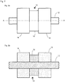
- Fig. 4 shows an illustration similar to that of Fig. 1 .
- the first and second members are respectively arranged on a respective support structure 26, 28.
- Each support structure comprising a respective supply shaft 30, 32 through which supply cables 34, e.g. electric cables, lubrication cables etc., can be fed to the actuator 18 for the operation thereof.
- supply cables 34 e.g. electric cables, lubrication cables etc.
- device cables 36 e.g. a cable of a camera (not shown) can be guided within the structure 12 in an interior of the convertor 10. This can for example be done to prevent the cable 36 of the camera from becoming stuck within the structure 12.
- Such an assembly can be used as an inspection device or in order to transport further components (not shown) within the structure 12.
- Each of the first and second members 14, 16 of Fig. 4 has a coating or layer 38, 40 provided thereon.
- This coating or layer 38, 40 is a friction enhancing coating or layer which generates an increased coefficient of friction with the structure 12 and prevents unwanted slippage of the first and second members 14, 16 which is engaging the structure 12 at any one time.
- This coating or layer 38, 40 can naturally be included in any type of convertor in accordance with the present invention.
- the convertor 10 of Fig. 4 is capable of moving within the structure 12 like the convertor 10 of Fig. 1 .
- the difference between Figs. 1 and 4 is that the support structures 26, 28 are to a large extent not affected by the changes in shape of the first and second members 14, 16 brought about by means of the actuator 18.
- the linear movement of the convertor 10 is however substantially unaffected by this alternative design.
- the convertor 10 of Figs. 1 a to 1 d can be considered to be a system which employs two contact segments which are joined and acted on by a single axial actuator 18, i.e. an actuator 18 which alternates between a state in which it simultaneously exerts a compressive force on both of the contact segments and a second state in which it simultaneously exerts a tensile force on both contact segments.
- the front contact segment is made from an auxetic material.
- the rear segment is made from a material having a positive Poisson's ratio.
- the magnitude of the Poisson's ratio of the first and second members 14, 16 are approximately the same albeit their signs being different.
- the system moves within a closely fitting tube which it touches only through the front and rear contact segments. Alternatively it could move along a central shaft (see e.g. Fig. 2 ).
- auxetic materials i.e. materials having a negative Poisson's ratio are: some single crystal organic species, and specially processed foams and engineered composite materials having reentrant structures also known as mechanical metamaterial having reentrant structure and exhibiting auxetic behavior.
- material having a positive Poisson's ratio are: virtually all common engineering materials: metals, e.g. aluminium, stainless steel etc., polymers, and ceramics.
- the alternator requires energy so that the convertor 10 could also be considered to convert energy into unidirectional movement.
- the space between these plates could then be varied by applying either a vacuum or an overpressure between these plates causing the plates to either move towards one another or apart from one another in order to effect a simultaneous tensile or compressive force on the first and second members 14, 16.
Claims (15)
- Convertisseur (10) pour convertir un mouvement alternatif en un mouvement unidirectionnel, le convertisseur (10) comprenant un actionneur (18) pour générer de mouvement alternatif, l'actionneur (18) étant disposé pour exercer des forces de compression et de traction sur un premier et un second élément (14, 16), le premiers desdits éléments ayant un rapport de Poisson positif et le second desdits éléments ayant un rapport de Poisson négatif, et le premier et le second élément (14, 16) sont adaptés pour un engagement en friction différentielle avec une structure (12).
- Convertisseur (10) selon la revendication 1, dans lequel le mouvement unidirectionnel est au moins un mouvement parmi un mouvement linéaire et un mouvement rotatif.
- Convertisseur (10) selon la revendication 1 ou 2, dans lequel le convertisseur (10) est installé à l'intérieur de la structure, comme un tube, grâce à quoi le convertisseur (10) se déplace de manière unidirectionnelle à l'intérieur de la structure (12).
- Convertisseur (10) selon la revendication 1 ou 2, dans lequel le convertisseur (10) peut être installé à l'extérieur de la structure (12), comme un tube ou une corde, grâce à quoi le convertisseur (10) se déplace de manière unidirectionnelle à l'extérieur de la structure (12).
- Convertisseur (10) selon l'une quelconque des revendications précédentes, dans lequel le mouvement alternatif est un mouvement parmi un mouvement cyclique et un mouvement oscillatoire, tels que des mouvements alternatifs d'expansion et de contraction générée par un moteur rotatif ou une pression générée par un mouvement alternatif entre un état en expansion et un état contracté.
- Convertisseur (10) selon l'une quelconque des revendications précédentes,
dans lequel l'actionneur (18) est un élément sélectionné parmi le groupe comprenant un actionneur pneumatique (18), un actionneur hydraulique (18), un actionneur piézoélectrique (18), un actionneur électrostatique (18), un actionneur électromagnétique (18) et un moteur à combustion interne. - Convertisseur (10) selon l'une quelconque des revendications précédentes, comprenant en outre une pluralité de paires formées d'un premier et d'un second élément (14, 16).
- Convertisseur (10) selon la revendication 7, comprenant en outre une pluralité d'actionneurs (18), les actionneurs (18) étant disposés pour exercer des forces de compression et de traction sur la pluralité de paires formées d'un premier et d'un second élément (14, 16).
- Convertisseur (10) selon la revendication 7 ou 8, dans lequel la pluralité de paires formées d'un premier et d'un second élément (14, 16) sont utilisées pour effectuer un mouvement de rotation unidirectionnelle par rapport à la structure (12).
- Convertisseur (10) selon l'une quelconque des revendications précédentes, dans lequel le convertisseur (10) est utilisé dans un appareil adapté à l'une des tâches suivantes, sélectionnée parmi le groupe comprenant l'avancée d'une tige de soudage, le nettoyage de structures, comme un pipeline, l'ascension sur un câble, comme un dispositif d'inspection, par exemple dans des égouts et dans des tubes, comme pour l'inspection des soudures, à titre de dispositif de mise en place, par exemple dans des réacteurs nucléaires pour éviter l'exposition humaine aux radiations ou pour éviter d'ouvrir un récipient ou de placer une caméra, dans des applications médicales, par exemple pour l'inspection de vaisseaux sanguins et la mise en place de stents.
- Convertisseur (10) selon l'une au moins des revendications précédentes, dans lequel le convertisseur (10) est utilisé à titre de pompe afin d'effectuer un mouvement de substances par rapport à la structure, par exemple pour déplacer une colonne de liquide le long d'un tube.
- Convertisseur (10) selon l'une quelconque des revendications précédentes, dans lequel la structure (12) est un élément sélectionné parmi le groupe comprenant une structure ouverte, une structure partiellement fermée, et une structure fermée.
- Convertisseur (10) selon l'une quelconque des revendications précédentes, dans lequel le convertisseur (10) fait partie d'un appareil fonctionnant comme un parmi un moteur à chenille, un moteur pas à pas, un appareil d'amenée, une pompe péristaltique, et un racleur de pipeline.
- Convertisseur (10) selon l'une quelconque des revendications précédentes,
dans lequel le premier desdits éléments (14) ayant un rapport de Poisson positif est fait d'un matériau sélectionné parmi le groupe de matériaux comprenant métal, caoutchouc, matière plastique, polymère, céramique et leurs combinaisons, et/ou dans lequel le seconds desdits éléments (16) ayant un rapport de Poisson négatif est un matériau sélectionné parmi le groupe de matériaux comprenant une mousse ou un autre matériau métallique mécanique ayant une structure rentrante et présentant un comportement auxétique, et/ou dans lequel le premier et le second élément (14, 16) comprennent en outre un revêtement ou une couche extérieure renforçant la friction (38, 40). - Convertisseur (10) selon l'une quelconque des revendications précédentes, dans lequel le rapport de Poisson du premier élément (14) est de -1,0 à -0,05, dans lequel le rapport de Poisson du second élément (16) est de 0,05 à 0,5, et le rapport des rapports de Poisson du premier et du second élément (14, 16) est dans la plage de 0,7 à 2,0.
Priority Applications (2)
| Application Number | Priority Date | Filing Date | Title |
|---|---|---|---|
| EP14170314.0A EP2949937B1 (fr) | 2014-05-28 | 2014-05-28 | Convertisseur |
| US14/722,574 US20150345479A1 (en) | 2014-05-28 | 2015-05-27 | Convertor |
Applications Claiming Priority (1)
| Application Number | Priority Date | Filing Date | Title |
|---|---|---|---|
| EP14170314.0A EP2949937B1 (fr) | 2014-05-28 | 2014-05-28 | Convertisseur |
Publications (2)
| Publication Number | Publication Date |
|---|---|
| EP2949937A1 EP2949937A1 (fr) | 2015-12-02 |
| EP2949937B1 true EP2949937B1 (fr) | 2016-12-21 |
Family
ID=50884246
Family Applications (1)
| Application Number | Title | Priority Date | Filing Date |
|---|---|---|---|
| EP14170314.0A Not-in-force EP2949937B1 (fr) | 2014-05-28 | 2014-05-28 | Convertisseur |
Country Status (2)
| Country | Link |
|---|---|
| US (1) | US20150345479A1 (fr) |
| EP (1) | EP2949937B1 (fr) |
Families Citing this family (5)
| Publication number | Priority date | Publication date | Assignee | Title |
|---|---|---|---|---|
| US10850406B2 (en) * | 2017-04-27 | 2020-12-01 | Massachusetts Institute Of Technology | Non-planar shearing auxetic structures, devices, and methods |
| GB201711002D0 (en) | 2017-07-07 | 2017-08-23 | Optical Metrology Services Ltd | Cable management apparatus and system |
| CN112044883A (zh) * | 2020-08-11 | 2020-12-08 | 肖勇强 | 一种管道疏通器 |
| CN111969327B (zh) * | 2020-08-21 | 2021-10-15 | 北京化工大学 | 一种形变可设计且可非接触控制的二维机械超材料 |
| CN113914699A (zh) * | 2021-09-30 | 2022-01-11 | 兰州理工大学 | 一种基于负泊松效应的输电铁塔抗风阻尼结构 |
Family Cites Families (4)
| Publication number | Priority date | Publication date | Assignee | Title |
|---|---|---|---|---|
| US3902084A (en) | 1974-05-30 | 1975-08-26 | Burleigh Instr | Piezoelectric electromechanical translation apparatus |
| US8302696B2 (en) | 2010-04-06 | 2012-11-06 | Baker Hughes Incorporated | Actuator and tubular actuator |
| JP5637785B2 (ja) * | 2010-09-06 | 2014-12-10 | キヤノン株式会社 | 原版、及びそれを用いた物品の製造方法 |
| WO2012071477A2 (fr) * | 2010-11-22 | 2012-05-31 | The Regents Of The University Of California | Biomatériaux microstructurés et procédés de fabrication de ceux-ci |
-
2014
- 2014-05-28 EP EP14170314.0A patent/EP2949937B1/fr not_active Not-in-force
-
2015
- 2015-05-27 US US14/722,574 patent/US20150345479A1/en not_active Abandoned
Non-Patent Citations (1)
| Title |
|---|
| None * |
Also Published As
| Publication number | Publication date |
|---|---|
| EP2949937A1 (fr) | 2015-12-02 |
| US20150345479A1 (en) | 2015-12-03 |
Similar Documents
| Publication | Publication Date | Title |
|---|---|---|
| EP2949937B1 (fr) | Convertisseur | |
| De Greef et al. | Towards flexible medical instruments: Review of flexible fluidic actuators | |
| CN104271961B (zh) | 对能线性运动的元件的位置进行调节的致动器装置及方法 | |
| US8904919B2 (en) | Extensile fluidic muscle actuator | |
| US10525588B2 (en) | Cable-driven system with magnetorheological fluid clutch apparatuses | |
| US10557550B2 (en) | Flexible joint | |
| Suzumori et al. | Long bending rubber mechanism combined contracting and extending tluidic actuators | |
| Miyasaka et al. | Long-mover: Flexible tube in-pipe inspection robot for long distance and complex piping | |
| JPH0324303A (ja) | 弾性伸長体を用いたアクチュエータ | |
| EP1883764A1 (fr) | Piece de raccordement articule pour tubes | |
| EP3230585A1 (fr) | Agencement d'éléments de fil dans un dispositif de récupération d'énergie | |
| JP6576642B2 (ja) | 部材の並進運動を制御するための伝動装置と、このような伝動装置を備えてブレーキ倍力装置を形成するブレーキシステム | |
| WO2011023145A1 (fr) | Équipement de pompage de béton et son corps de piston | |
| JP2010127429A (ja) | 流体アクチュエータ | |
| CA3108101A1 (fr) | Systeme de revetement pour l'integration d'un equipement modulaire d'intervention interne dans des conduits tubulaires | |
| Qiao et al. | Unilateral self-locking mechanism for inchworm in-pipe robot | |
| AU2019217162B2 (en) | Wave force generation system and controlling method therefor | |
| AU2007278577A1 (en) | Device for connecting a section of a pipe run to a pulling element | |
| JP2007253281A (ja) | 自動走行ロボット | |
| RU2475909C1 (ru) | Транспортное средство для перемещения по внутренним поверхностям | |
| JP4737608B2 (ja) | マッキベン型アクチュエータ及びマッキベン型アクチュエータによる負荷牽引装置及び方法 | |
| US3135296A (en) | Laminated tubing | |
| JPH033791A (ja) | 弾性収縮体を用いたマニプレータ | |
| JP6893652B2 (ja) | 移動体および探索機 | |
| Bai et al. | Design and verification of a micro pipe robot |
Legal Events
| Date | Code | Title | Description |
|---|---|---|---|
| AK | Designated contracting states |
Kind code of ref document: A1 Designated state(s): AL AT BE BG CH CY CZ DE DK EE ES FI FR GB GR HR HU IE IS IT LI LT LU LV MC MK MT NL NO PL PT RO RS SE SI SK SM TR |
|
| AX | Request for extension of the european patent |
Extension state: BA ME |
|
| PUAI | Public reference made under article 153(3) epc to a published international application that has entered the european phase |
Free format text: ORIGINAL CODE: 0009012 |
|
| 17P | Request for examination filed |
Effective date: 20160518 |
|
| GRAP | Despatch of communication of intention to grant a patent |
Free format text: ORIGINAL CODE: EPIDOSNIGR1 |
|
| RBV | Designated contracting states (corrected) |
Designated state(s): AL AT BE BG CH CY CZ DE DK EE ES FI FR GB GR HR HU IE IS IT LI LT LU LV MC MK MT NL NO PL PT RO RS SE SI SK SM TR |
|
| INTG | Intention to grant announced |
Effective date: 20160630 |
|
| RAP1 | Party data changed (applicant data changed or rights of an application transferred) |
Owner name: MAX-PLANCK-GESELLSCHAFT ZUR FOERDERUNG DER WISSENS |
|
| GRAS | Grant fee paid |
Free format text: ORIGINAL CODE: EPIDOSNIGR3 |
|
| GRAA | (expected) grant |
Free format text: ORIGINAL CODE: 0009210 |
|
| AK | Designated contracting states |
Kind code of ref document: B1 Designated state(s): AL AT BE BG CH CY CZ DE DK EE ES FI FR GB GR HR HU IE IS IT LI LT LU LV MC MK MT NL NO PL PT RO RS SE SI SK SM TR |
|
| REG | Reference to a national code |
Ref country code: GB Ref legal event code: FG4D |
|
| REG | Reference to a national code |
Ref country code: CH Ref legal event code: EP |
|
| REG | Reference to a national code |
Ref country code: IE Ref legal event code: FG4D |
|
| REG | Reference to a national code |
Ref country code: AT Ref legal event code: REF Ref document number: 855750 Country of ref document: AT Kind code of ref document: T Effective date: 20170115 |
|
| REG | Reference to a national code |
Ref country code: DE Ref legal event code: R096 Ref document number: 602014005588 Country of ref document: DE |
|
| PG25 | Lapsed in a contracting state [announced via postgrant information from national office to epo] |
Ref country code: LV Free format text: LAPSE BECAUSE OF FAILURE TO SUBMIT A TRANSLATION OF THE DESCRIPTION OR TO PAY THE FEE WITHIN THE PRESCRIBED TIME-LIMIT Effective date: 20161221 |
|
| REG | Reference to a national code |
Ref country code: LT Ref legal event code: MG4D |
|
| REG | Reference to a national code |
Ref country code: NL Ref legal event code: MP Effective date: 20161221 |
|
| PG25 | Lapsed in a contracting state [announced via postgrant information from national office to epo] |
Ref country code: GR Free format text: LAPSE BECAUSE OF FAILURE TO SUBMIT A TRANSLATION OF THE DESCRIPTION OR TO PAY THE FEE WITHIN THE PRESCRIBED TIME-LIMIT Effective date: 20170322 Ref country code: LT Free format text: LAPSE BECAUSE OF FAILURE TO SUBMIT A TRANSLATION OF THE DESCRIPTION OR TO PAY THE FEE WITHIN THE PRESCRIBED TIME-LIMIT Effective date: 20161221 Ref country code: SE Free format text: LAPSE BECAUSE OF FAILURE TO SUBMIT A TRANSLATION OF THE DESCRIPTION OR TO PAY THE FEE WITHIN THE PRESCRIBED TIME-LIMIT Effective date: 20161221 Ref country code: NO Free format text: LAPSE BECAUSE OF FAILURE TO SUBMIT A TRANSLATION OF THE DESCRIPTION OR TO PAY THE FEE WITHIN THE PRESCRIBED TIME-LIMIT Effective date: 20170321 |
|
| REG | Reference to a national code |
Ref country code: AT Ref legal event code: MK05 Ref document number: 855750 Country of ref document: AT Kind code of ref document: T Effective date: 20161221 |
|
| REG | Reference to a national code |
Ref country code: FR Ref legal event code: PLFP Year of fee payment: 4 |
|
| PG25 | Lapsed in a contracting state [announced via postgrant information from national office to epo] |
Ref country code: FI Free format text: LAPSE BECAUSE OF FAILURE TO SUBMIT A TRANSLATION OF THE DESCRIPTION OR TO PAY THE FEE WITHIN THE PRESCRIBED TIME-LIMIT Effective date: 20161221 Ref country code: HR Free format text: LAPSE BECAUSE OF FAILURE TO SUBMIT A TRANSLATION OF THE DESCRIPTION OR TO PAY THE FEE WITHIN THE PRESCRIBED TIME-LIMIT Effective date: 20161221 Ref country code: RS Free format text: LAPSE BECAUSE OF FAILURE TO SUBMIT A TRANSLATION OF THE DESCRIPTION OR TO PAY THE FEE WITHIN THE PRESCRIBED TIME-LIMIT Effective date: 20161221 |
|
| PG25 | Lapsed in a contracting state [announced via postgrant information from national office to epo] |
Ref country code: NL Free format text: LAPSE BECAUSE OF FAILURE TO SUBMIT A TRANSLATION OF THE DESCRIPTION OR TO PAY THE FEE WITHIN THE PRESCRIBED TIME-LIMIT Effective date: 20161221 |
|
| PG25 | Lapsed in a contracting state [announced via postgrant information from national office to epo] |
Ref country code: CZ Free format text: LAPSE BECAUSE OF FAILURE TO SUBMIT A TRANSLATION OF THE DESCRIPTION OR TO PAY THE FEE WITHIN THE PRESCRIBED TIME-LIMIT Effective date: 20161221 Ref country code: RO Free format text: LAPSE BECAUSE OF FAILURE TO SUBMIT A TRANSLATION OF THE DESCRIPTION OR TO PAY THE FEE WITHIN THE PRESCRIBED TIME-LIMIT Effective date: 20161221 Ref country code: SK Free format text: LAPSE BECAUSE OF FAILURE TO SUBMIT A TRANSLATION OF THE DESCRIPTION OR TO PAY THE FEE WITHIN THE PRESCRIBED TIME-LIMIT Effective date: 20161221 Ref country code: IS Free format text: LAPSE BECAUSE OF FAILURE TO SUBMIT A TRANSLATION OF THE DESCRIPTION OR TO PAY THE FEE WITHIN THE PRESCRIBED TIME-LIMIT Effective date: 20170421 Ref country code: EE Free format text: LAPSE BECAUSE OF FAILURE TO SUBMIT A TRANSLATION OF THE DESCRIPTION OR TO PAY THE FEE WITHIN THE PRESCRIBED TIME-LIMIT Effective date: 20161221 |
|
| PG25 | Lapsed in a contracting state [announced via postgrant information from national office to epo] |
Ref country code: LU Free format text: LAPSE BECAUSE OF NON-PAYMENT OF DUE FEES Effective date: 20170531 Ref country code: AT Free format text: LAPSE BECAUSE OF FAILURE TO SUBMIT A TRANSLATION OF THE DESCRIPTION OR TO PAY THE FEE WITHIN THE PRESCRIBED TIME-LIMIT Effective date: 20161221 Ref country code: BE Free format text: LAPSE BECAUSE OF FAILURE TO SUBMIT A TRANSLATION OF THE DESCRIPTION OR TO PAY THE FEE WITHIN THE PRESCRIBED TIME-LIMIT Effective date: 20161221 Ref country code: SM Free format text: LAPSE BECAUSE OF FAILURE TO SUBMIT A TRANSLATION OF THE DESCRIPTION OR TO PAY THE FEE WITHIN THE PRESCRIBED TIME-LIMIT Effective date: 20161221 Ref country code: ES Free format text: LAPSE BECAUSE OF FAILURE TO SUBMIT A TRANSLATION OF THE DESCRIPTION OR TO PAY THE FEE WITHIN THE PRESCRIBED TIME-LIMIT Effective date: 20161221 Ref country code: PT Free format text: LAPSE BECAUSE OF FAILURE TO SUBMIT A TRANSLATION OF THE DESCRIPTION OR TO PAY THE FEE WITHIN THE PRESCRIBED TIME-LIMIT Effective date: 20170421 Ref country code: BG Free format text: LAPSE BECAUSE OF FAILURE TO SUBMIT A TRANSLATION OF THE DESCRIPTION OR TO PAY THE FEE WITHIN THE PRESCRIBED TIME-LIMIT Effective date: 20170321 Ref country code: PL Free format text: LAPSE BECAUSE OF FAILURE TO SUBMIT A TRANSLATION OF THE DESCRIPTION OR TO PAY THE FEE WITHIN THE PRESCRIBED TIME-LIMIT Effective date: 20161221 Ref country code: IT Free format text: LAPSE BECAUSE OF FAILURE TO SUBMIT A TRANSLATION OF THE DESCRIPTION OR TO PAY THE FEE WITHIN THE PRESCRIBED TIME-LIMIT Effective date: 20161221 |
|
| REG | Reference to a national code |
Ref country code: DE Ref legal event code: R097 Ref document number: 602014005588 Country of ref document: DE |
|
| PLBE | No opposition filed within time limit |
Free format text: ORIGINAL CODE: 0009261 |
|
| STAA | Information on the status of an ep patent application or granted ep patent |
Free format text: STATUS: NO OPPOSITION FILED WITHIN TIME LIMIT |
|
| 26N | No opposition filed |
Effective date: 20170922 |
|
| PG25 | Lapsed in a contracting state [announced via postgrant information from national office to epo] |
Ref country code: DK Free format text: LAPSE BECAUSE OF FAILURE TO SUBMIT A TRANSLATION OF THE DESCRIPTION OR TO PAY THE FEE WITHIN THE PRESCRIBED TIME-LIMIT Effective date: 20161221 |
|
| REG | Reference to a national code |
Ref country code: CH Ref legal event code: PL |
|
| PG25 | Lapsed in a contracting state [announced via postgrant information from national office to epo] |
Ref country code: MC Free format text: LAPSE BECAUSE OF FAILURE TO SUBMIT A TRANSLATION OF THE DESCRIPTION OR TO PAY THE FEE WITHIN THE PRESCRIBED TIME-LIMIT Effective date: 20161221 |
|
| REG | Reference to a national code |
Ref country code: IE Ref legal event code: MM4A |
|
| PG25 | Lapsed in a contracting state [announced via postgrant information from national office to epo] |
Ref country code: LI Free format text: LAPSE BECAUSE OF NON-PAYMENT OF DUE FEES Effective date: 20170531 Ref country code: SI Free format text: LAPSE BECAUSE OF FAILURE TO SUBMIT A TRANSLATION OF THE DESCRIPTION OR TO PAY THE FEE WITHIN THE PRESCRIBED TIME-LIMIT Effective date: 20161221 Ref country code: CH Free format text: LAPSE BECAUSE OF NON-PAYMENT OF DUE FEES Effective date: 20170531 |
|
| PG25 | Lapsed in a contracting state [announced via postgrant information from national office to epo] |
Ref country code: LU Free format text: LAPSE BECAUSE OF NON-PAYMENT OF DUE FEES Effective date: 20170528 |
|
| PG25 | Lapsed in a contracting state [announced via postgrant information from national office to epo] |
Ref country code: IE Free format text: LAPSE BECAUSE OF NON-PAYMENT OF DUE FEES Effective date: 20170528 |
|
| REG | Reference to a national code |
Ref country code: FR Ref legal event code: PLFP Year of fee payment: 5 |
|
| PG25 | Lapsed in a contracting state [announced via postgrant information from national office to epo] |
Ref country code: MT Free format text: LAPSE BECAUSE OF NON-PAYMENT OF DUE FEES Effective date: 20170528 |
|
| PG25 | Lapsed in a contracting state [announced via postgrant information from national office to epo] |
Ref country code: HU Free format text: LAPSE BECAUSE OF FAILURE TO SUBMIT A TRANSLATION OF THE DESCRIPTION OR TO PAY THE FEE WITHIN THE PRESCRIBED TIME-LIMIT; INVALID AB INITIO Effective date: 20140528 |
|
| PG25 | Lapsed in a contracting state [announced via postgrant information from national office to epo] |
Ref country code: CY Free format text: LAPSE BECAUSE OF FAILURE TO SUBMIT A TRANSLATION OF THE DESCRIPTION OR TO PAY THE FEE WITHIN THE PRESCRIBED TIME-LIMIT Effective date: 20161221 |
|
| PG25 | Lapsed in a contracting state [announced via postgrant information from national office to epo] |
Ref country code: MK Free format text: LAPSE BECAUSE OF FAILURE TO SUBMIT A TRANSLATION OF THE DESCRIPTION OR TO PAY THE FEE WITHIN THE PRESCRIBED TIME-LIMIT Effective date: 20161221 |
|
| PG25 | Lapsed in a contracting state [announced via postgrant information from national office to epo] |
Ref country code: TR Free format text: LAPSE BECAUSE OF FAILURE TO SUBMIT A TRANSLATION OF THE DESCRIPTION OR TO PAY THE FEE WITHIN THE PRESCRIBED TIME-LIMIT Effective date: 20161221 |
|
| PG25 | Lapsed in a contracting state [announced via postgrant information from national office to epo] |
Ref country code: AL Free format text: LAPSE BECAUSE OF FAILURE TO SUBMIT A TRANSLATION OF THE DESCRIPTION OR TO PAY THE FEE WITHIN THE PRESCRIBED TIME-LIMIT Effective date: 20161221 |
|
| PGFP | Annual fee paid to national office [announced via postgrant information from national office to epo] |
Ref country code: FR Payment date: 20200522 Year of fee payment: 7 |
|
| PGFP | Annual fee paid to national office [announced via postgrant information from national office to epo] |
Ref country code: GB Payment date: 20200527 Year of fee payment: 7 |
|
| PGFP | Annual fee paid to national office [announced via postgrant information from national office to epo] |
Ref country code: DE Payment date: 20200730 Year of fee payment: 7 |
|
| REG | Reference to a national code |
Ref country code: DE Ref legal event code: R119 Ref document number: 602014005588 Country of ref document: DE |
|
| GBPC | Gb: european patent ceased through non-payment of renewal fee |
Effective date: 20210528 |
|
| PG25 | Lapsed in a contracting state [announced via postgrant information from national office to epo] |
Ref country code: GB Free format text: LAPSE BECAUSE OF NON-PAYMENT OF DUE FEES Effective date: 20210528 Ref country code: DE Free format text: LAPSE BECAUSE OF NON-PAYMENT OF DUE FEES Effective date: 20211201 |
|
| PG25 | Lapsed in a contracting state [announced via postgrant information from national office to epo] |
Ref country code: FR Free format text: LAPSE BECAUSE OF NON-PAYMENT OF DUE FEES Effective date: 20210531 |