EP2949916A1 - Fuel injector - Google Patents
Fuel injector Download PDFInfo
- Publication number
- EP2949916A1 EP2949916A1 EP15168422.2A EP15168422A EP2949916A1 EP 2949916 A1 EP2949916 A1 EP 2949916A1 EP 15168422 A EP15168422 A EP 15168422A EP 2949916 A1 EP2949916 A1 EP 2949916A1
- Authority
- EP
- European Patent Office
- Prior art keywords
- injector
- intake port
- fuel
- valve
- chamber
- Prior art date
- Legal status (The legal status is an assumption and is not a legal conclusion. Google has not performed a legal analysis and makes no representation as to the accuracy of the status listed.)
- Withdrawn
Links
Images


Classifications
-
- F—MECHANICAL ENGINEERING; LIGHTING; HEATING; WEAPONS; BLASTING
- F02—COMBUSTION ENGINES; HOT-GAS OR COMBUSTION-PRODUCT ENGINE PLANTS
- F02M—SUPPLYING COMBUSTION ENGINES IN GENERAL WITH COMBUSTIBLE MIXTURES OR CONSTITUENTS THEREOF
- F02M61/00—Fuel-injectors not provided for in groups F02M39/00 - F02M57/00 or F02M67/00
- F02M61/16—Details not provided for in, or of interest apart from, the apparatus of groups F02M61/02 - F02M61/14
- F02M61/18—Injection nozzles, e.g. having valve seats; Details of valve member seated ends, not otherwise provided for
- F02M61/1893—Details of valve member ends not covered by groups F02M61/1866 - F02M61/188
-
- F—MECHANICAL ENGINEERING; LIGHTING; HEATING; WEAPONS; BLASTING
- F02—COMBUSTION ENGINES; HOT-GAS OR COMBUSTION-PRODUCT ENGINE PLANTS
- F02M—SUPPLYING COMBUSTION ENGINES IN GENERAL WITH COMBUSTIBLE MIXTURES OR CONSTITUENTS THEREOF
- F02M47/00—Fuel-injection apparatus operated cyclically with fuel-injection valves actuated by fluid pressure
- F02M47/04—Fuel-injection apparatus operated cyclically with fuel-injection valves actuated by fluid pressure using fluid, other than fuel, for injection-valve actuation
- F02M47/043—Fluid pressure acting on injection-valve in the period of non-injection to keep it closed
-
- F—MECHANICAL ENGINEERING; LIGHTING; HEATING; WEAPONS; BLASTING
- F02—COMBUSTION ENGINES; HOT-GAS OR COMBUSTION-PRODUCT ENGINE PLANTS
- F02B—INTERNAL-COMBUSTION PISTON ENGINES; COMBUSTION ENGINES IN GENERAL
- F02B23/00—Other engines characterised by special shape or construction of combustion chambers to improve operation
- F02B23/02—Other engines characterised by special shape or construction of combustion chambers to improve operation with compression ignition
- F02B23/06—Other engines characterised by special shape or construction of combustion chambers to improve operation with compression ignition the combustion space being arranged in working piston
- F02B23/0645—Details related to the fuel injector or the fuel spray
- F02B23/0663—Details related to the fuel injector or the fuel spray having multiple injectors per combustion chamber
-
- F—MECHANICAL ENGINEERING; LIGHTING; HEATING; WEAPONS; BLASTING
- F02—COMBUSTION ENGINES; HOT-GAS OR COMBUSTION-PRODUCT ENGINE PLANTS
- F02B—INTERNAL-COMBUSTION PISTON ENGINES; COMBUSTION ENGINES IN GENERAL
- F02B23/00—Other engines characterised by special shape or construction of combustion chambers to improve operation
- F02B23/02—Other engines characterised by special shape or construction of combustion chambers to improve operation with compression ignition
- F02B23/06—Other engines characterised by special shape or construction of combustion chambers to improve operation with compression ignition the combustion space being arranged in working piston
- F02B23/0696—W-piston bowl, i.e. the combustion space having a central projection pointing towards the cylinder head and the surrounding wall being inclined towards the cylinder wall
-
- F—MECHANICAL ENGINEERING; LIGHTING; HEATING; WEAPONS; BLASTING
- F02—COMBUSTION ENGINES; HOT-GAS OR COMBUSTION-PRODUCT ENGINE PLANTS
- F02D—CONTROLLING COMBUSTION ENGINES
- F02D19/00—Controlling engines characterised by their use of non-liquid fuels, pluralities of fuels, or non-fuel substances added to the combustible mixtures
- F02D19/06—Controlling engines characterised by their use of non-liquid fuels, pluralities of fuels, or non-fuel substances added to the combustible mixtures peculiar to engines working with pluralities of fuels, e.g. alternatively with light and heavy fuel oil, other than engines indifferent to the fuel consumed
- F02D19/0663—Details on the fuel supply system, e.g. tanks, valves, pipes, pumps, rails, injectors or mixers
- F02D19/0686—Injectors
- F02D19/0689—Injectors for in-cylinder direct injection
-
- F—MECHANICAL ENGINEERING; LIGHTING; HEATING; WEAPONS; BLASTING
- F02—COMBUSTION ENGINES; HOT-GAS OR COMBUSTION-PRODUCT ENGINE PLANTS
- F02D—CONTROLLING COMBUSTION ENGINES
- F02D19/00—Controlling engines characterised by their use of non-liquid fuels, pluralities of fuels, or non-fuel substances added to the combustible mixtures
- F02D19/06—Controlling engines characterised by their use of non-liquid fuels, pluralities of fuels, or non-fuel substances added to the combustible mixtures peculiar to engines working with pluralities of fuels, e.g. alternatively with light and heavy fuel oil, other than engines indifferent to the fuel consumed
- F02D19/0663—Details on the fuel supply system, e.g. tanks, valves, pipes, pumps, rails, injectors or mixers
- F02D19/0686—Injectors
- F02D19/0692—Arrangement of multiple injectors per combustion chamber
-
- F—MECHANICAL ENGINEERING; LIGHTING; HEATING; WEAPONS; BLASTING
- F02—COMBUSTION ENGINES; HOT-GAS OR COMBUSTION-PRODUCT ENGINE PLANTS
- F02D—CONTROLLING COMBUSTION ENGINES
- F02D19/00—Controlling engines characterised by their use of non-liquid fuels, pluralities of fuels, or non-fuel substances added to the combustible mixtures
- F02D19/06—Controlling engines characterised by their use of non-liquid fuels, pluralities of fuels, or non-fuel substances added to the combustible mixtures peculiar to engines working with pluralities of fuels, e.g. alternatively with light and heavy fuel oil, other than engines indifferent to the fuel consumed
- F02D19/08—Controlling engines characterised by their use of non-liquid fuels, pluralities of fuels, or non-fuel substances added to the combustible mixtures peculiar to engines working with pluralities of fuels, e.g. alternatively with light and heavy fuel oil, other than engines indifferent to the fuel consumed simultaneously using pluralities of fuels
- F02D19/10—Controlling engines characterised by their use of non-liquid fuels, pluralities of fuels, or non-fuel substances added to the combustible mixtures peculiar to engines working with pluralities of fuels, e.g. alternatively with light and heavy fuel oil, other than engines indifferent to the fuel consumed simultaneously using pluralities of fuels peculiar to compression-ignition engines in which the main fuel is gaseous
-
- F—MECHANICAL ENGINEERING; LIGHTING; HEATING; WEAPONS; BLASTING
- F02—COMBUSTION ENGINES; HOT-GAS OR COMBUSTION-PRODUCT ENGINE PLANTS
- F02M—SUPPLYING COMBUSTION ENGINES IN GENERAL WITH COMBUSTIBLE MIXTURES OR CONSTITUENTS THEREOF
- F02M21/00—Apparatus for supplying engines with non-liquid fuels, e.g. gaseous fuels stored in liquid form
- F02M21/02—Apparatus for supplying engines with non-liquid fuels, e.g. gaseous fuels stored in liquid form for gaseous fuels
- F02M21/0218—Details on the gaseous fuel supply system, e.g. tanks, valves, pipes, pumps, rails, injectors or mixers
- F02M21/0248—Injectors
- F02M21/0251—Details of actuators therefor
-
- F—MECHANICAL ENGINEERING; LIGHTING; HEATING; WEAPONS; BLASTING
- F02—COMBUSTION ENGINES; HOT-GAS OR COMBUSTION-PRODUCT ENGINE PLANTS
- F02M—SUPPLYING COMBUSTION ENGINES IN GENERAL WITH COMBUSTIBLE MIXTURES OR CONSTITUENTS THEREOF
- F02M21/00—Apparatus for supplying engines with non-liquid fuels, e.g. gaseous fuels stored in liquid form
- F02M21/02—Apparatus for supplying engines with non-liquid fuels, e.g. gaseous fuels stored in liquid form for gaseous fuels
- F02M21/0218—Details on the gaseous fuel supply system, e.g. tanks, valves, pipes, pumps, rails, injectors or mixers
- F02M21/0248—Injectors
- F02M21/0257—Details of the valve closing elements, e.g. valve seats, stems or arrangement of flow passages
- F02M21/026—Lift valves, i.e. stem operated valves
- F02M21/0263—Inwardly opening single or multi nozzle valves, e.g. needle valves
-
- F—MECHANICAL ENGINEERING; LIGHTING; HEATING; WEAPONS; BLASTING
- F02—COMBUSTION ENGINES; HOT-GAS OR COMBUSTION-PRODUCT ENGINE PLANTS
- F02M—SUPPLYING COMBUSTION ENGINES IN GENERAL WITH COMBUSTIBLE MIXTURES OR CONSTITUENTS THEREOF
- F02M21/00—Apparatus for supplying engines with non-liquid fuels, e.g. gaseous fuels stored in liquid form
- F02M21/02—Apparatus for supplying engines with non-liquid fuels, e.g. gaseous fuels stored in liquid form for gaseous fuels
- F02M21/0218—Details on the gaseous fuel supply system, e.g. tanks, valves, pipes, pumps, rails, injectors or mixers
- F02M21/0248—Injectors
- F02M21/0275—Injectors for in-cylinder direct injection, e.g. injector combined with spark plug
-
- F—MECHANICAL ENGINEERING; LIGHTING; HEATING; WEAPONS; BLASTING
- F02—COMBUSTION ENGINES; HOT-GAS OR COMBUSTION-PRODUCT ENGINE PLANTS
- F02M—SUPPLYING COMBUSTION ENGINES IN GENERAL WITH COMBUSTIBLE MIXTURES OR CONSTITUENTS THEREOF
- F02M43/00—Fuel-injection apparatus operating simultaneously on two or more fuels, or on a liquid fuel and another liquid, e.g. the other liquid being an anti-knock additive
- F02M43/04—Injectors peculiar thereto
-
- F—MECHANICAL ENGINEERING; LIGHTING; HEATING; WEAPONS; BLASTING
- F02—COMBUSTION ENGINES; HOT-GAS OR COMBUSTION-PRODUCT ENGINE PLANTS
- F02M—SUPPLYING COMBUSTION ENGINES IN GENERAL WITH COMBUSTIBLE MIXTURES OR CONSTITUENTS THEREOF
- F02M47/00—Fuel-injection apparatus operated cyclically with fuel-injection valves actuated by fluid pressure
- F02M47/02—Fuel-injection apparatus operated cyclically with fuel-injection valves actuated by fluid pressure of accumulator-injector type, i.e. having fuel pressure of accumulator tending to open, and fuel pressure in other chamber tending to close, injection valves and having means for periodically releasing that closing pressure
- F02M47/022—Mechanically actuated valves draining the chamber to release the closing pressure
-
- F—MECHANICAL ENGINEERING; LIGHTING; HEATING; WEAPONS; BLASTING
- F02—COMBUSTION ENGINES; HOT-GAS OR COMBUSTION-PRODUCT ENGINE PLANTS
- F02M—SUPPLYING COMBUSTION ENGINES IN GENERAL WITH COMBUSTIBLE MIXTURES OR CONSTITUENTS THEREOF
- F02M47/00—Fuel-injection apparatus operated cyclically with fuel-injection valves actuated by fluid pressure
- F02M47/02—Fuel-injection apparatus operated cyclically with fuel-injection valves actuated by fluid pressure of accumulator-injector type, i.e. having fuel pressure of accumulator tending to open, and fuel pressure in other chamber tending to close, injection valves and having means for periodically releasing that closing pressure
- F02M47/027—Electrically actuated valves draining the chamber to release the closing pressure
-
- F—MECHANICAL ENGINEERING; LIGHTING; HEATING; WEAPONS; BLASTING
- F02—COMBUSTION ENGINES; HOT-GAS OR COMBUSTION-PRODUCT ENGINE PLANTS
- F02M—SUPPLYING COMBUSTION ENGINES IN GENERAL WITH COMBUSTIBLE MIXTURES OR CONSTITUENTS THEREOF
- F02M47/00—Fuel-injection apparatus operated cyclically with fuel-injection valves actuated by fluid pressure
- F02M47/04—Fuel-injection apparatus operated cyclically with fuel-injection valves actuated by fluid pressure using fluid, other than fuel, for injection-valve actuation
-
- F—MECHANICAL ENGINEERING; LIGHTING; HEATING; WEAPONS; BLASTING
- F02—COMBUSTION ENGINES; HOT-GAS OR COMBUSTION-PRODUCT ENGINE PLANTS
- F02M—SUPPLYING COMBUSTION ENGINES IN GENERAL WITH COMBUSTIBLE MIXTURES OR CONSTITUENTS THEREOF
- F02M55/00—Fuel-injection apparatus characterised by their fuel conduits or their venting means; Arrangements of conduits between fuel tank and pump F02M37/00
- F02M55/008—Arrangement of fuel passages inside of injectors
-
- F—MECHANICAL ENGINEERING; LIGHTING; HEATING; WEAPONS; BLASTING
- F02—COMBUSTION ENGINES; HOT-GAS OR COMBUSTION-PRODUCT ENGINE PLANTS
- F02M—SUPPLYING COMBUSTION ENGINES IN GENERAL WITH COMBUSTIBLE MIXTURES OR CONSTITUENTS THEREOF
- F02M61/00—Fuel-injectors not provided for in groups F02M39/00 - F02M57/00 or F02M67/00
- F02M61/04—Fuel-injectors not provided for in groups F02M39/00 - F02M57/00 or F02M67/00 having valves, e.g. having a plurality of valves in series
-
- F—MECHANICAL ENGINEERING; LIGHTING; HEATING; WEAPONS; BLASTING
- F02—COMBUSTION ENGINES; HOT-GAS OR COMBUSTION-PRODUCT ENGINE PLANTS
- F02M—SUPPLYING COMBUSTION ENGINES IN GENERAL WITH COMBUSTIBLE MIXTURES OR CONSTITUENTS THEREOF
- F02M63/00—Other fuel-injection apparatus having pertinent characteristics not provided for in groups F02M39/00 - F02M57/00 or F02M67/00; Details, component parts, or accessories of fuel-injection apparatus, not provided for in, or of interest apart from, the apparatus of groups F02M39/00 - F02M61/00 or F02M67/00; Combination of fuel pump with other devices, e.g. lubricating oil pump
- F02M63/02—Fuel-injection apparatus having several injectors fed by a common pumping element, or having several pumping elements feeding a common injector; Fuel-injection apparatus having provisions for cutting-out pumps, pumping elements, or injectors; Fuel-injection apparatus having provisions for variably interconnecting pumping elements and injectors alternatively
-
- F—MECHANICAL ENGINEERING; LIGHTING; HEATING; WEAPONS; BLASTING
- F02—COMBUSTION ENGINES; HOT-GAS OR COMBUSTION-PRODUCT ENGINE PLANTS
- F02M—SUPPLYING COMBUSTION ENGINES IN GENERAL WITH COMBUSTIBLE MIXTURES OR CONSTITUENTS THEREOF
- F02M2200/00—Details of fuel-injection apparatus, not otherwise provided for
- F02M2200/30—Fuel-injection apparatus having mechanical parts, the movement of which is damped
- F02M2200/304—Fuel-injection apparatus having mechanical parts, the movement of which is damped using hydraulic means
-
- F—MECHANICAL ENGINEERING; LIGHTING; HEATING; WEAPONS; BLASTING
- F02—COMBUSTION ENGINES; HOT-GAS OR COMBUSTION-PRODUCT ENGINE PLANTS
- F02M—SUPPLYING COMBUSTION ENGINES IN GENERAL WITH COMBUSTIBLE MIXTURES OR CONSTITUENTS THEREOF
- F02M2200/00—Details of fuel-injection apparatus, not otherwise provided for
- F02M2200/40—Fuel-injection apparatus with fuel accumulators, e.g. a fuel injector having an integrated fuel accumulator
-
- F—MECHANICAL ENGINEERING; LIGHTING; HEATING; WEAPONS; BLASTING
- F02—COMBUSTION ENGINES; HOT-GAS OR COMBUSTION-PRODUCT ENGINE PLANTS
- F02M—SUPPLYING COMBUSTION ENGINES IN GENERAL WITH COMBUSTIBLE MIXTURES OR CONSTITUENTS THEREOF
- F02M63/00—Other fuel-injection apparatus having pertinent characteristics not provided for in groups F02M39/00 - F02M57/00 or F02M67/00; Details, component parts, or accessories of fuel-injection apparatus, not provided for in, or of interest apart from, the apparatus of groups F02M39/00 - F02M61/00 or F02M67/00; Combination of fuel pump with other devices, e.g. lubricating oil pump
- F02M63/0012—Valves
- F02M63/007—Details not provided for in, or of interest apart from, the apparatus of the groups F02M63/0014 - F02M63/0059
- F02M63/0078—Valve member details, e.g. special shape, hollow or fuel passages in the valve member
-
- Y—GENERAL TAGGING OF NEW TECHNOLOGICAL DEVELOPMENTS; GENERAL TAGGING OF CROSS-SECTIONAL TECHNOLOGIES SPANNING OVER SEVERAL SECTIONS OF THE IPC; TECHNICAL SUBJECTS COVERED BY FORMER USPC CROSS-REFERENCE ART COLLECTIONS [XRACs] AND DIGESTS
- Y02—TECHNOLOGIES OR APPLICATIONS FOR MITIGATION OR ADAPTATION AGAINST CLIMATE CHANGE
- Y02T—CLIMATE CHANGE MITIGATION TECHNOLOGIES RELATED TO TRANSPORTATION
- Y02T10/00—Road transport of goods or passengers
- Y02T10/10—Internal combustion engine [ICE] based vehicles
- Y02T10/12—Improving ICE efficiencies
-
- Y—GENERAL TAGGING OF NEW TECHNOLOGICAL DEVELOPMENTS; GENERAL TAGGING OF CROSS-SECTIONAL TECHNOLOGIES SPANNING OVER SEVERAL SECTIONS OF THE IPC; TECHNICAL SUBJECTS COVERED BY FORMER USPC CROSS-REFERENCE ART COLLECTIONS [XRACs] AND DIGESTS
- Y02—TECHNOLOGIES OR APPLICATIONS FOR MITIGATION OR ADAPTATION AGAINST CLIMATE CHANGE
- Y02T—CLIMATE CHANGE MITIGATION TECHNOLOGIES RELATED TO TRANSPORTATION
- Y02T10/00—Road transport of goods or passengers
- Y02T10/10—Internal combustion engine [ICE] based vehicles
- Y02T10/30—Use of alternative fuels, e.g. biofuels
Definitions
- the present disclosure relates to a fuel injector. More particularly, the present disclosure relates to a high-pressure direct injector for natural gas.
- Fuel injectors are used in a variety of applications to deliver a fuel, such as gasoline, to an engine.
- a series of fuel injectors may be incorporated into each of the various cylinders in the engine to deliver the fuel that will drive the pistons and power the engine.
- the present disclosure provides a fuel injector.
- the fuel injector may include an injector body and an injector valve.
- the injector body may define a longitudinally extending chamber and may include a first intake port, a second intake port and a fuel injection port.
- the injector valve may be disposed within the chamber and may include a longitudinally extending aperture in fluid communication with the longitudinally extending chamber.
- the injector valve may be configured to prevent fluid communication between the first intake port and the second intake port, and may be configured to prevent fluid communication between the fuel injection port and the second intake port.
- the fuel injector may include a biasing member disposed within the chamber.
- the biasing member may be configured to bias the injector valve into engagement with the injector body.
- the fuel injector may include a biasing member disposed within the chamber.
- the biasing member may be configured to bias the injector valve into engagement with the injector body to prevent fluid communication between the at least one fuel injection port and the second intake port.
- the injector valve may include an annular flanged portion.
- the annular flanged portion may be operable to engage the injector body to define a gap between the injector valve and the injector body.
- the fuel injector may include a control valve.
- the control valve may be operable to prevent fluid communication between the first intake port and the chamber.
- the first intake port is an oil intake port and the second intake port is a natural gas intake port.
- the injector valve includes a longitudinally extending aperture.
- the longitudinally extending aperture is in fluid communication with the longitudinally extending chamber.
- the chamber includes first and second portions at least partially defined by the injector valve and the injector body.
- the injector valve may prevent fluid communication between the first and second portions.
- the injector body includes a conically shaped end portion.
- the injector valve includes a conically shaped tip portion disposed within the end portion.
- the tip portion includes an annular flanged portion operable to engage the end portion.
- the present disclosure provides a fuel injector.
- the fuel injector may include an injector body and an injector valve.
- the injector body may define a longitudinally extending chamber and include a first intake port, a second intake port and at least one fuel injection port.
- the first intake port may be configured to deliver a first fluid into the chamber.
- the first fluid may apply a first force on the injector valve.
- the second intake port may be configured to deliver a second fluid into the chamber.
- the second fluid may apply a second force on the injector valve.
- the second force may oppose the first force.
- the injector valve may be disposed within the chamber and may be configured to prevent fluid communication between the first intake port and the second intake port.
- the present disclosure provides method for operating a fuel injector.
- the fuel injector including may include an injector body defining a longitudinally extending chamber, and an injector valve slidably disposed within the longitudinally extending chamber.
- the injector body may include a first intake port, a second intake port, and a fuel injection port.
- the method may also include allowing the first fluid to flow into the longitudinally extending aperture to apply a first force on the injector valve in a first direction, such that the injector valve moves in the first direction within the longitudinally extending chamber and engages the injector body to prevent fluid communication between the second intake port and the at least one fuel injection port.
- Example embodiments are provided so that this disclosure will be thorough, and will fully convey the scope to those who are skilled in the art. Numerous specific details are set forth such as examples of specific components, devices, and methods, to provide a thorough understanding of embodiments of the present disclosure. It will be apparent to those skilled in the art that specific details need not be employed, that example embodiments may be embodied in many different forms and that neither should be construed to limit the scope of the disclosure. In some example embodiments, well-known processes, well-known device structures, and well-known technologies are not described in detail.
- first, second, third, etc. may be used herein to describe various elements, components, regions, layers and/or sections, these elements, components, regions, layers and/or sections should not be limited by these terms. These terms may be only used to distinguish one element, component, region, layer or section from another region, layer or section. Terms such as “first,” “second,” and other numerical terms when used herein do not imply a sequence or order unless clearly indicated by the context. Thus, a first element, component, region, layer or section discussed below could be termed a second element, component, region, layer or section without departing from the teachings of the example embodiments.
- spatially relative terms such as “inner,” “outer,” “beneath,” “below,” “lower,” “above,” “upper,” and the like, may be used herein for ease of description to describe one element or feature's relationship to another element(s) or feature(s) as illustrated in the figures.
- Spatially relative terms may be intended to encompass different orientations of the device in use or operation in addition to the orientation depicted in the figures. For example, if the device in the figures is turned over, elements described as “below” or “beneath” other elements or features would then be oriented “above” the other elements or features.
- the example term “below” can encompass both an orientation of above and below.
- the device may be otherwise oriented (rotated 90 degrees or at other orientations) and the spatially relative descriptors used herein interpreted accordingly.
- an engine 10 is provided and may include a cylinder 12 and a piston 14. While only one cylinder 12 and one piston 14 are shown, it will be appreciated that the engine 10 may include any number of cylinders 12 and pistons 14, as is known in the art.
- the cylinder 12 may include a cylinder block 20 and a cylinder head 22.
- the cylinder block 20 and cylinder head 22 may define a chamber 24 having a central, longitudinal axis 18.
- the piston 14 may slide or otherwise move along the central axis 18 within the chamber 24 to drive a crankshaft (not shown) and provide power to the engine 10.
- the cylinder head 22 may include at least one intake valve assembly 26 and at least one exhaust valve assembly 28. In one configuration, the cylinder head 22 includes two intake valve assemblies 26 and two exhaust valve assemblies 28.
- the intake valve assemblies 26 may deliver air from an intake source (not shown) to the chamber 24 while the exhaust valve assemblies 28 deliver combustion exhaust from the chamber 24 to an exhaust system (not shown).
- At least one bore 30a may be formed in the cylinder head 22 or the cylinder block 20.
- the cylinder head 22 includes two bores 30a located proximate to the central axis 18, and generally central to the intake valve assemblies 26 and the exhaust valve assemblies 28.
- a longitudinal axis 31 of one of the bores 30a may be disposed at an angle ( ⁇ ) relative to the central axis 18.
- the cylinder head 22 includes two bores 30b. At least one of the bores 30b may be substantially aligned with the central axis 18, while another of the bores 30b may be disposed substantially adjacent to and between the intake valve assemblies 26. Accordingly, a longitudinal axis 33 of one of the bores 30b may be disposed at an angle ( ⁇ ) relative to the central axis 18.
- the cylinder 12 may further include at least one fuel injector 34.
- the fuel injector 34 may be a high-pressure fuel injector that injects natural gas into the chamber 24 of the cylinder 12. While the fuel injector 34 is described as injecting natural gas, the fuel injector 34 may inject any other suitable fuel into the chamber 24.
- the fuel injector 34 may be disposed in one of the bores 30a, 30b while a diesel injector 36, a spark plug (not shown), or another suitable device (e.g., a micro-pilot) for igniting the fuel supplied by the fuel injector 34 may be disposed in the other bore 30a, 30b.
- a diesel injector 36 e.g., a spark plug
- another suitable device e.g., a micro-pilot
- the fuel injector 34 may be disposed within an intake port 38 of an engine 10.
- the intake port 38 may be in fluid communication with at least one intake valve assembly 26. Accordingly, the fuel injector 34 may deliver fuel to the chamber 24 via the intake port 38.
- the fuel injector 34 may include an injector body 40, a needle or injector valve 42, a biasing member 44, and a control valve assembly 46.
- the injector body 40 may include a base portion 48 and a tip portion 50.
- the base 48 and the tip 50 may define an inner chamber 53.
- the tip 50 may be fastened to the base 48 using a threaded configuration, a press-fit configuration, or by using other suitable mechanical fastening techniques.
- the tip 50 may be integrally formed with the base 48 in a monolithic construct.
- the base 48 may extend from a proximal end 52 to a distal end 54 along a longitudinal axis 56.
- the distal end 54 may form an annular shoulder 58 extending between and connecting the base 48 and the tip 50.
- the base 48 may be a generally cylindrical construct having a diameter D1
- the tip 50 may be a generally cylindrical construct having a diameter D2 ( FIG. 4A ).
- the diameter D1 may be larger than the diameter D2.
- injector body 40 may be disposed within the bore 30 such that the shoulder 58 is disposed against a portion of the cylinder head 22 or a portion of the intake port 38.
- the injector 34 may include a gasket 59 or similar sealing feature disposed between the shoulder 58 and the cylinder head 22 to provide a sealed interface between the injector body 40 and the cylinder head 22.
- the tip 50 may extend from a proximal end 60, adjacent the distal end 54 of the base 48, to a distal end 62 along the longitudinal axis 56.
- the distal end 62 of the tip 50 may be generally conically shaped.
- the tip 50 may include between two (2) and twelve (12) apertures or fuel injection ports 64 that provide fluid communication with the chamber 53. It will be appreciated that the number and configuration of the fuel injection ports 64 may vary depending on the particular use or application of the fuel injector 34.
- the chamber 53 may extend along the longitudinal axis 56 and may include a first portion 66 and a second portion 68.
- An annular flange or shoulder 70 may extend between and connect the first portion 66 and the second portion 68.
- the first portion 66 may be a generally cylindrical chamber having a diameter D3
- the second portion 68 may be a cylindrical chamber having a diameter D4 ( FIG. 4A ).
- the diameter D3 may be larger than the diameter D4.
- the conical configuration of the distal end 62 of the tip 50 may generally define a conical configuration at a distal end 71 of the chamber 53 thereof.
- the injector 34 may further include a first intake port 74 and a second intake port 76.
- the first intake port 74 may be disposed in the control valve assembly 46 and may be in fluid communication with the first portion 66 of the chamber 53.
- the first intake port 74 may be a high-pressure oil supply port or, alternatively, may supply any suitable fluid to the first portion 66 of the chamber 53.
- the second intake port 76 may extend through the injector body 40 and may be in fluid communication with the second portion 68 of the chamber 53.
- the second intake port 76 may be an aperture formed through a sidewall of the base 48.
- the second intake port 76 may be a high-pressure natural gas port or, alternatively, may supply any suitable fluid to the second portion 68 of the chamber 53.
- the injector valve 42 may be located within the chamber 53 of the injector body 40 and translates within the chamber 53 in a direction substantially parallel to the longitudinal axis 56.
- the injector valve 42 may extend from a proximal end 78 to a distal end 80 along the longitudinal axis 56.
- the injector valve 42 may include first, second and third stem portions 86a, 86b, 86c and a tip portion 88.
- An annular flange or shoulder 83 may extend radially outward from the injector valve 42 between the first stem portion 86a and the second stem portion 86b. In one configuration, the shoulder 83 may be generally conically shaped.
- a longitudinally extending bore 84 may extend at least partially through the first, second and third stem portions 86a, 86b, 86c and the tip portion 88, such that at least a portion of the injector valve 42 is a generally hollow construct.
- the second stem portion 86b may be separated from the third stem portion 86c by an annular shoulder 94.
- the second stem portion 86b may be a generally cylindrical construct having a diameter D5
- the third stem portion 86c may be a cylindrical construct having a diameter D6 ( FIG. 4A ).
- the diameter D5 may be larger than the diameter D6 and may be substantially equal to the diameter D4 of the second portion 68 of the chamber 53.
- the second stem portion 86b of the injector valve 42 may be sealingly disposed within the second portion 68 of the chamber 53 such that the injector valve 42 prevents fluid communication between first and second portions 66, 68 of the chamber 53, and thereby prevents fluid communication between the first and second intake ports 64, 74.
- the injector 34 may include an annular space or gap between the third stem portion 86c and the injector body 40 at the second portion 68 of the chamber 53.
- the tip portion 88 of the injector valve 42 may extend from the third stem portion 86c and may include a conically shaped surface 96, such that the tip portion 88 is receivable within the conically shaped distal end 71 of the chamber 53.
- the tip portion 88 may further include a radially extending flanged portion 98 having a first annular surface 100 and a second annular surface 102.
- the second annular surface 102 may be substantially frustoconically shaped.
- the second annular surface 102 of the flanged portion 98 may be adjacent to, and sealingly engaged with, the tip 50 of the injector body 40.
- the flanged portion 98 may define a conically shaped space or gap 104 between the tip 50 of the injector body and the tip portion 88 of the injector valve 42.
- the fuel injection ports 64 may be in fluid communication with the gap 104.
- the flanged portion 98 may prevent the fuel injection ports 64 from fluidly communicating with the second portion 68 of the chamber 53 and with the second intake port 76.
- the gap 104 ensures that the tip portion 88 of the injector valve 42 does not contact the fuel injection ports 64, which can help ensure that contaminant build-up or surface abnormalities on the tip portion 88 do not affect the performance of the injection ports 64. Accordingly, the flanged portion 98 and the gap 104 may ensure better sealing of the injection ports 64 when the injector valve 42 is in the seated configuration ( FIG. 4A ) and may provide better flow characteristics between the injection ports 64 and the second portion 68 of the chamber 53 when injector valve 42 is in an unseated configuration ( FIG. 4B )
- the biasing member 44 may be located in the first portion 66 of the chamber 53.
- the biasing member 44 is a helical spring concentrically disposed about the first stem portion 86a of the injector valve 42, such that the first stem portion 86a axially supports the biasing member 44.
- the biasing member 44 may include a first end 106 disposed adjacent the control valve assembly 46 and a second end 108 disposed adjacent the shoulder 83. In this way, the biasing member 44 biases the injector valve 42 along the longitudinal axis 56 such that the flange portion 98 of the injector valve 42 is sealingly engaged with the tip 50 of the injector body 40, as previously described.
- the control valve assembly 46 may prevent fluid communication between the first intake port 74 and the first portion 66 of the chamber 53 in a first configuration ( FIG. 4A ) and may allow fluid communication between the first intake port 74 and the first portion 66 of the chamber 53 in a second configuration ( FIG. 4B ).
- the fuel injector 134 may include an injector body 140, a needle or injector valve 142, a biasing member 144, and a control valve assembly 146.
- like reference numerals are used hereinafter to identify like components while like reference numerals having one hundred (100) added to the number of the corresponding element of the fuel injector 34 are used to identify those components that have been modified.
- the fuel injector 134 may generally be integrated with the cylinder head 22.
- the outer surface of the injector body 140 may include at least one annular channel 148.
- the injector body 140 includes two channels 148. It will appreciated, however, that the injector body may include less or more than two channels 148 within the scope of the present teachings.
- An O-ring 150 or other suitable sealing feature may be disposed within each of the channels 148 to seal a junction of the injector body 140 and the cylinder head 22.
- the cylinder head 22 may include a third intake port 154 and a fourth intake port 156.
- the fuel injector 134 may be disposed within one of the bores 30a, 30b of the cylinder head 22 such that the O-rings 150 or other suitable seals provide a sealed interface between the cylinder head 22 and the injector body 140.
- the third intake port 154 of the cylinder head 22 may be in fluid communication with the first intake port 174
- the fourth intake port 156 may be in fluid communication with the second intake port 176 in the injector body 140.
- at least one of the O-rings 150 may prevent fluid communication between the third intake port 154 and the fourth intake port 156.
- a fuel pressure regulating system 200 including another configuration of a fuel injector 234, is shown.
- the fuel pressure regulating system 200 may include the injector 234, an oil pump 236, a first fuel tank 238 (e.g., a liquid natural gas tank), a fuel pump 240 (e.g., a liquid natural gas pump), a second fuel tank 242 (e.g., a compressed natural gas pump), a fuel pressure regulator 244, and a pressure relief valve 246.
- the injector 234 may be substantially similar to the fuel injectors 34, 134, except as otherwise described herein. Accordingly, like reference numerals are used to identify like components while like reference numerals having two hundred (200) added to the number of the corresponding element of the fuel injector 34 are used to identify those components that have been modified.
- the injector 234 may include an accumulator 250.
- the accumulator 250 may include an axially extending flange or wall 252 extending from a distal end 254 of the base portion 248 of the injector 234.
- the wall 252 may define a chamber 256.
- the wall 252 may be coupled to a proximal end 258 of an injector body 260, such that the chamber 256 may be in fluid communication with a second intake port 261 and with the second portion 68 of the chamber 53.
- the wall 252 may be substantially cylindrical such that the chamber 256 annularly surrounds, and is concentrically located relative to, the injector valve 42.
- the wall 252 may have an inner diameter D7 that is greater than the diameter D4 of the second portion 68 of the chamber 53 and is greater than the diameter D5 of second stem portion 86b of the injector valve 42.
- the diameter D7 of the chamber 256 may define an accumulator volume that is larger than a volume that would otherwise be defined by the diameter D4 of the second portion 68 of the chamber 53 ( Figure 4A ).
- the accumulator 250 including the accumulator volume of the chamber 256, may allow the injector 234 to deliver fuel through the injection ports 64 and into the chamber 24 of the cylinder 12 in a very short period of time.
- the accumulator 250 may allow the injector 234 to deliver fuel to the chamber 24 in approximately thirty (30) crank degrees, such that, of the seven hundred twenty (720) crank degrees in a four-cycle engine, one hundred percent (100%) of the fuel may be delivered in four percent (4%) of the total cycle time. Placing the accumulator 250, including the chamber 256 directly in line with, and concentric to, the injector valve 42 and the second portion 68 of the chamber 53, can help to avoid line losses and other inefficiencies during operation of the injector 234.
- the pressure relief valve 246 may include a housing 262, a valve member 264, and a biasing member 265.
- the housing 262 may define an inner chamber 266, and may include a first inlet port 268, a second inlet port 270, a first outlet port 272, and a second outlet port 274.
- the first inlet port 268 may be an oil inlet port in fluid communication with the chamber 266 and with the oil pump 236.
- the second inlet port 270 may be a compressed natural gas port in fluid communication with the chamber 266 and with the fuel pressure regulator 244.
- the first outlet port 272 may be a compressed natural gas port in fluid communication with the second intake port 261 of the fuel injector 234.
- the second outlet port 274 may be a compressed natural gas port in fluid communication with the first fuel tank 238.
- the valve member 264 may be disposed within the chamber 266 of the housing 262 and may include a body portion 276 and a stem portion 278. In an assembled configuration, the body portion 276 may sealingly engage an inner surface 280 of the housing 262, such that the body portion 276 divides the chamber 266 into a first portion 266a and a second portion 266b. As illustrated, the first inlet port 268 may be in fluid communication with the first portion 266a of the chamber 266, while the second inlet port 270 and the first and second outlet ports 272, 274 may be in fluid communication with the second portion 266b of the chamber 266.
- the stem portion 278 of the valve member 264 may extend from the body portion 276. In an assembled configuration, the stem portion 278 may be aligned with the second outlet port 274, such that the stem portion 278 prevents fluid communication between the second portion 266b of the chamber 266 and second outlet port 274, as will be described in more detail below.
- the biasing member 265 may be disposed within the chamber 266 and may be a helical spring disposed between the housing 262 and the valve member 264. The biasing member 265 biases the stem portion 278 away from the second outlet port 274, to allow fluid communication between the second outlet port 274 and the second portion 266b of the chamber 266.
- a first flow path 282 (e.g., a first conduit) may extend from and between the oil pump 236, the first inlet port 268, and the first intake port 74. Accordingly, the first flow path 282 may allow the oil pump 236 to fluidly communicate with both the first intake port 74 of the injector 234 and with the first inlet port 268 of the pressure relief valve 246.
- a second flow path 284 (e.g., a second conduit) may extend from and between the second inlet port 270 and the second outlet port 274.
- the second flow path 284 may include the first fuel tank 238, the fuel pump 240, the second fuel tank 242, and the fuel pressure regulator 244. Accordingly, and as will be described in more detail below, the second flow path 284 allows the second inlet port 270 to fluidly communicate with the second outlet port 274.
- a third flow path 286 (e.g., a third conduit) may extend from and between the first outlet port 272 and the second intake port 261 of the fuel injector 234. Accordingly, the third flow path 286 allows the first outlet port 272 to fluidly communicate with the second intake port 261.
- FIG. 6B another configuration of a fuel pressure regulating system 300 is shown.
- the fuel pressure regulating system 300 is substantially identical to the fuel pressure regulating system 200, except as described below. Accordingly, like reference numerals are used to describe like features and components. Similar features will not be described again in detail.
- the fuel pressure regulating system 300 may include the injector 234, the oil pump 236, the first fuel tank 238, the fuel pump 240, the second fuel tank 242, the fuel pressure regulator 244, and a pressure relief valve 246a.
- a third flow path 286a (e.g., a third conduit) may extend from and between the second flow path 284 and the second intake port 261 of the injector 234. Accordingly, the third flow path 286a may allow the second outlet port 274 to fluidly communicate with the second intake port 261.
- a fuel pressure regulating system 400 including another configuration of a fuel injector 434, is shown.
- the fuel pressure regulating system 400 may include the injector 434, the oil pump 236, the first fuel tank 238, the fuel pump 240, the second fuel tank 242, the fuel pressure regulator 244, and the pressure relief valve 246.
- the injector 434 may be substantially similar to the fuel injectors 34, 134, 232 except as otherwise described herein. Accordingly, like reference numerals are used to identify like components while like reference numerals having four hundred (400) added to the number of the corresponding element of the fuel injector 34 are used to identify those components that have been modified.
- the injector 434 may include an injector body 440, an injector valve 442, and a biasing member 444.
- the injector valve 442 may extend from a proximal end 478 to a distal end 480 along the longitudinal axis 56.
- a first stem portion 486a of the injector valve 442 may include a bore 484 extending from an annular flange or shoulder 483 to the proximal end 478 of the injector valve 442.
- the first stem portion 486a of the injector valve 442 may disposed within the first portion 466 of the chamber 453, such that the first stem portion 486a, including the shoulder 483, separates a proximal end 491 of the first portion 466 from a distal end 493 of the first portion 466.
- the shoulder 483 may include a through hole or aperture 490 in fluid communication with the proximal and distal ends 491, 493 of the chamber 453.
- the first stem portion 486a may be sealingly disposed within the first portion 466 of the chamber 453, such that the first stem portion 486a prevents the proximal portion 491 of the chamber 453 from fluidly communicating with the distal portion 493 of the chamber 453, other than through the aperture 490.
- the biasing member 44 may be located within the bore 484. In one configuration, the biasing member 44 is concentrically disposed within the bore 484 of the first stem portion 486a, such that the second end 108 of the biasing member 44 engages the shoulder 483. In this way, the biasing member 44 biases the injector valve 442 along the longitudinal axis 56.
- the fuel injectors 34, 134, 234, 434 will now be described in detail with reference to FIGS. 4A-7 . Operation of the fuel injectors will be described relative to a force F1 applied by the biasing member 44, 144, 444, a force F2 applied by a first fluid supplied from the intake port 76, 176, 261, and a force F3 applied by a second fluid supplied from the intake port 74, 174.
- the fuel injectors 34, 134, 234, 434 may be disposed within the cylinder block 20, the cylinder head 22, or the intake port 38 such that the fuel injection ports 64 fluidly communicate with the chamber 24.
- the control valve assembly 46 in a first mode of operation, may be in a closed configuration, thereby preventing fluid communication between the first intake port 74 and the first portion 66 of the chamber 53.
- the biasing member 44 may apply the force F1 on the injector valve 42.
- a high pressure fluid e.g., engine oil from a motor vehicle
- the biasing member 44 biases the tip portion 88 into engagement with the tip 50 of the injector body 40, such that the second annular surface 102 prevents fluid communication between the fuel injection ports 64 and the second intake port 76.
- the biasing member 44 may act as a fail-safe mechanism to prevent fluid communication between the fuel injection ports 64 and the chamber 24 when the control valve assembly 46 is in the closed configuration and high-pressure fluid is not supplied to the first intake port 74 (e.g., when engine power is turned off).
- the control valve assembly 46 in a second mode of operation, may be in an open configuration, thereby allowing fluid communication between the first intake port 74 and the first portion 66 of the chamber 53.
- the biasing member 44 may apply the force F1 on the injector valve 42, and a high-pressure fluid (e.g., engine oil from a motor vehicle) may apply the force F3 on the proximal end 78 of the injector valve 42, to bias the tip portion 88 into engagement with the tip 50 of the injector body 40, such that the second annular surface 102 prevents fluid communication between the fuel injection ports 64 and the second intake port 76.
- a high-pressure fluid e.g., engine oil from a motor vehicle
- high-pressure gas or other suitable fluid, may be supplied to the second portion 68 of the chamber 53 and/or to the chamber 256 of the accumulator 250 ( FIG. 6A ), respectively, as described above.
- the force F3 may be substantially opposite, and greater than, the force F2 provided by the high-pressure gas.
- control valve assembly 46 may be in a closed configuration, thereby preventing fluid communication between the first intake port 74 and the first portion 66 of the chamber 53.
- High-pressure gas, or other suitable fluid may be supplied from the second intake port 76, 176 to the second portion 68 of the chamber 53 and/or to the chamber 256 of the accumulator 250, respectively.
- the high-pressure gas may fill the annular gap between the injector valve 42 and the injector body 40 and may apply the force F2 on the shoulder 94 of the injector valve 42 to bias the tip portion 88 away from the tip 50 of the injector body 40, such that the fuel injection ports 64 are placed in fluid communication with the second portion 68 of the chamber 53 and with the second intake port 76. Accordingly, the force F2 may be substantially opposite, and greater than, the force F1 provided by the biasing member 44.
- high-pressure oil may be supplied, or otherwise transported, through the first flow path 282.
- high-pressure oil from the oil pump 236 may be supplied to the first intake port 74 of the fuel injector 234 and to the first inlet port 268 of the pressure relief valve 246.
- operation of the fuel injector 234 may be substantially similar to operation of the fuel injectors 34, 134.
- the high-pressure oil supplied to the first inlet port 268 of the pressure relief valve 246 and, thus, to the first portion 266a of the chamber 266, may apply a force on the valve member 264 that is opposite, and greater than, a force applied on the valve member 264 by the biasing member 265.
- the high-pressure oil may bias the stem portion 278 of the valve member 264 into a closed position relative to the second outlet port 274, such that the valve member 264 prevents fluid communication between the second outlet port 274 and the second portion 266b of the chamber 266.
- Natural gas may be supplied or otherwise transported through the second flow path 284. Specifically, natural gas from the first fuel tank 238 may first be supplied to the second fuel tank 242 by the fuel pump 240. The natural gas may further be supplied or transported from the second fuel tank 242 to the fuel pressure regulator 244, and from the fuel pressure regulator 244 to the second inlet port 270 of the pressure relief valve 246.
- the fuel pressure regulating system 200 may further include a controller 298 (e.g., an engine control unit).
- the controller 298 may be in communication with the oil pump 236, the fuel pump 240, the fuel pressure regulator 244, and/or with the injector 234, to control various characteristics (e.g., pressure, quantity, and duration) of the supply of oil and natural gas to the first and second inlet ports 268, 270, respectively.
- the force of the biasing member 265 and/or a force created on the valve member 264 by the natural gas within the second portion 266b of the chamber 266 may urge the stem portion 278 of the valve member 264 away from the second outlet port 274, such that the second outlet port is in fluid communication with the second portion 266b of the chamber 266.
- the pressure relief valve 246 can operate as a fail-safe mechanism, allowing for the movement of natural gas from the fuel pressure regulator 244 to the first fuel tank 238, when natural gas is supplied to the second inlet port 270 and oil is not supplied, or is otherwise supplied at a pressure that is lower than a predetermined value, to the first inlet port 268.
- Operation of the fuel pressure regulating system 300 may be substantially similar to operation of the fuel pressure regulating system 200, except as otherwise described herein.
- Natural gas may be supplied or transported from the second flow path 284 to the second intake port 261 of the injector 234 and to the second portion 266b of the of chamber 266 of the pressure relief valve 246a. Specifically, the natural gas may be transported from the first fuel tank 238 to the second fuel tank 242, from the second fuel tank 242 to the fuel pressure regulator 244, and from the fuel pressure regulator 244 to the third flow path 286a, prior to entering the second intake port 261 of the injector 234 and the second inlet port 270 of the pressure relief valve 246a.
- the force of the biasing member 265 and/or a force created on the valve member 264 by the natural gas within the second portion 266b of the chamber 266 may urge the stem portion 278 of the valve member 264 away from the second outlet port 274, such that the second outlet port is in fluid communication with the second portion 266b of the chamber 266.
- the pressure relief valve 246a can operate as a fail-safe mechanism, allowing for the movement of natural gas from the fuel pressure regulator 244 to the first fuel tank 238, when natural gas is supplied to the second inlet port 270 and oil is not supplied, or is otherwise supplied at a pressure that is lower than a predetermined value, to the first inlet port 268.
- operation of the fuel pressure regulating system 400 including the fuel injector 434 will now be described in more detail. Operation of the fuel pressure regulating system 400 and the fuel injector 434 may be substantially similar to the operation of the fuel pressure regulating systems 200, 300 and operation of the fuel injectors 34, 134, 234. Accordingly, only the differences will be discussed in detail herein.
- high-pressure oil may be supplied, or otherwise transported, through the first flow path 282. Specifically, high-pressure oil from the oil pump 236 may be supplied to the first intake port 74 of the fuel injector 434.
- control valve assembly 46 may be in an open configuration and high-pressure oil (e.g., engine oil from a motor vehicle), or other suitable fluid, may be supplied to the proximal end 491 of the chamber 453 from the first intake port 74.
- high-pressure oil e.g., engine oil from a motor vehicle
- the high-pressure oil may then flow into the bore 484 of the injector valve 442 and apply the force F3 on the shoulder 483 of the injector valve 442. Accordingly, the high-pressure oil will bias and translate the tip portion 488 of the injector valve 442 into engagement with the tip 450 of the injector body 440, such that the flanged portion 498 prevents fluid communication between the fuel injection ports 64 and the second intake port 261.
- the high-pressure oil supplied to the bore 484 may flow through the aperture 490 and into the distal end 493 of the chamber 453.
- the high-pressure oil flowing into the distal end 493 of the chamber 453 may apply a force F4 on the shoulder 483 of the injector valve 442.
- the force F4 may be opposite the force F3, such that the high-pressure oil and the force F4 act to dampen or otherwise slow the movement of the injector valve 442 relative to the injector body 440.
Abstract
Description
- This application claims the benefit of
U.S. Provisional Application No. 62/005,342 filed on May 30, 2014 - The present disclosure relates to a fuel injector. More particularly, the present disclosure relates to a high-pressure direct injector for natural gas.
- This section provides background information related to the present disclosure which is not necessarily prior art.
- Fuel injectors are used in a variety of applications to deliver a fuel, such as gasoline, to an engine. A series of fuel injectors may be incorporated into each of the various cylinders in the engine to deliver the fuel that will drive the pistons and power the engine. In some applications, it may be desirable to deliver a high-pressure natural gas to an engine via a fuel injector. In such instances, it may be desirable to have a fuel injector that can deliver fuel in multiple configurations and under various engine operating conditions and modes of operation.
- This section provides a general summary of the disclosure, and is not a comprehensive disclosure of its full scope or all of its features.
- According to one particular aspect, the present disclosure provides a fuel injector. The fuel injector may include an injector body and an injector valve. The injector body may define a longitudinally extending chamber and may include a first intake port, a second intake port and a fuel injection port. The injector valve may be disposed within the chamber and may include a longitudinally extending aperture in fluid communication with the longitudinally extending chamber. The injector valve may be configured to prevent fluid communication between the first intake port and the second intake port, and may be configured to prevent fluid communication between the fuel injection port and the second intake port.
- In some configurations, the fuel injector may include a biasing member disposed within the chamber. The biasing member may be configured to bias the injector valve into engagement with the injector body.
- In some configurations, the fuel injector may include a biasing member disposed within the chamber. The biasing member may be configured to bias the injector valve into engagement with the injector body to prevent fluid communication between the at least one fuel injection port and the second intake port.
- In some configurations, the injector valve may include an annular flanged portion. The annular flanged portion may be operable to engage the injector body to define a gap between the injector valve and the injector body.
- In some configurations, the fuel injector may include a control valve. The control valve may be operable to prevent fluid communication between the first intake port and the chamber.
- In some configurations, the first intake port is an oil intake port and the second intake port is a natural gas intake port.
- In some configurations, the injector valve includes a longitudinally extending aperture.
- In some configurations, the longitudinally extending aperture is in fluid communication with the longitudinally extending chamber.
- In some configurations, the chamber includes first and second portions at least partially defined by the injector valve and the injector body. The injector valve may prevent fluid communication between the first and second portions.
- In some configurations, the injector body includes a conically shaped end portion.
- In some configurations, the injector valve includes a conically shaped tip portion disposed within the end portion.
- In some configurations, the tip portion includes an annular flanged portion operable to engage the end portion.
- According to another particular aspect, the present disclosure provides a fuel injector. The fuel injector may include an injector body and an injector valve. The injector body may define a longitudinally extending chamber and include a first intake port, a second intake port and at least one fuel injection port. The first intake port may be configured to deliver a first fluid into the chamber. The first fluid may apply a first force on the injector valve. The second intake port may be configured to deliver a second fluid into the chamber. The second fluid may apply a second force on the injector valve. The second force may oppose the first force. The injector valve may be disposed within the chamber and may be configured to prevent fluid communication between the first intake port and the second intake port.
- According to yet another particular aspect, the present disclosure provides method for operating a fuel injector. The fuel injector including may include an injector body defining a longitudinally extending chamber, and an injector valve slidably disposed within the longitudinally extending chamber. The injector body may include a first intake port, a second intake port, and a fuel injection port. The injector valve may include a longitudinally extending aperture. The method may include allowing a first fluid to flow into the longitudinally extending chamber through the first intake port. The method may also include allowing the first fluid to flow into the longitudinally extending aperture to apply a first force on the injector valve in a first direction, such that the injector valve moves in the first direction within the longitudinally extending chamber and engages the injector body to prevent fluid communication between the second intake port and the at least one fuel injection port.
- Further areas of applicability will become apparent from the description provided herein. The description and specific examples in this summary are intended for purposes of illustration only and are not intended to limit the scope of the present disclosure.
- The drawings described herein are for illustrative purposes only of selected embodiments and not all possible implementations, and are not intended to limit the scope of the present disclosure.
-
FIG. 1A is a cross-sectional view of a cylinder incorporating a fuel injector in accordance with the principles of the present disclosure; -
FIG. 1B is a top view of the cylinder ofFIG. 1A ; -
FIG. 2A is another cross-sectional view of a cylinder incorporating a fuel injector in accordance with the principles of the present disclosure; -
FIG. 2B is a top view of the cylinder ofFIG. 2A ; -
FIG. 3 is another cross-sectional view of a cylinder incorporating a fuel injector in accordance with the principles of the present disclosure; -
FIG. 4A is a cross-sectional view of a fuel injector in a first configuration in accordance with the principles of the present disclosure; -
FIG. 4B is a cross-sectional view of the fuel injector ofFIG. 4A in a second configuration; -
FIG. 5 is a cross-sectional view of a fuel injector integrated into a cylinder in accordance with the principles of the present disclosure; -
FIG. 6A is a schematic view of a fuel pressure regulating system, including a cross-sectional view of a fuel injector having an accumulator, in accordance with the principles of the present disclosure; -
FIG. 6B is a schematic view of another configuration of a fuel pressure regulating system, including a cross-sectional view of a fuel injector having an accumulator, in accordance with the principles of the present disclosure; and -
FIG. 7 is a schematic view of another configuration of a fuel pressure regulating system, including a cross-sectional view of a fuel injector having an accumulator, in accordance with the principles of the present disclosure. - Corresponding reference numerals indicate corresponding parts throughout the several views of the drawings.
- Example embodiments will now be described more fully with reference to the accompanying drawings.
- Example embodiments are provided so that this disclosure will be thorough, and will fully convey the scope to those who are skilled in the art. Numerous specific details are set forth such as examples of specific components, devices, and methods, to provide a thorough understanding of embodiments of the present disclosure. It will be apparent to those skilled in the art that specific details need not be employed, that example embodiments may be embodied in many different forms and that neither should be construed to limit the scope of the disclosure. In some example embodiments, well-known processes, well-known device structures, and well-known technologies are not described in detail.
- The terminology used herein is for the purpose of describing particular example embodiments only and is not intended to be limiting. As used herein, the singular forms "a," "an," and "the" may be intended to include the plural forms as well, unless the context clearly indicates otherwise. The terms "comprises," "comprising," "including," and "having," are inclusive and therefore specify the presence of stated features, integers, steps, operations, elements, and/or components, but do not preclude the presence or addition of one or more other features, integers, steps, operations, elements, components, and/or groups thereof. The method steps, processes, and operations described herein are not to be construed as necessarily requiring their performance in the particular order discussed or illustrated, unless specifically identified as an order of performance. It is also to be understood that additional or alternative steps may be employed.
- When an element or layer is referred to as being "on," "engaged to," "connected to," or "coupled to" another element or layer, it may be directly on, engaged, connected or coupled to the other element or layer, or intervening elements or layers may be present. In contrast, when an element is referred to as being "directly on," "directly engaged to," "directly connected to," or "directly coupled to" another element or layer, there may be no intervening elements or layers present. Other words used to describe the relationship between elements should be interpreted in a like fashion (e.g., "between" versus "directly between," "adjacent" versus "directly adjacent," etc.). As used herein, the term "and/or" includes any and all combinations of one or more of the associated listed items.
- Although the terms first, second, third, etc. may be used herein to describe various elements, components, regions, layers and/or sections, these elements, components, regions, layers and/or sections should not be limited by these terms. These terms may be only used to distinguish one element, component, region, layer or section from another region, layer or section. Terms such as "first," "second," and other numerical terms when used herein do not imply a sequence or order unless clearly indicated by the context. Thus, a first element, component, region, layer or section discussed below could be termed a second element, component, region, layer or section without departing from the teachings of the example embodiments.
- Spatially relative terms, such as "inner," "outer," "beneath," "below," "lower," "above," "upper," and the like, may be used herein for ease of description to describe one element or feature's relationship to another element(s) or feature(s) as illustrated in the figures. Spatially relative terms may be intended to encompass different orientations of the device in use or operation in addition to the orientation depicted in the figures. For example, if the device in the figures is turned over, elements described as "below" or "beneath" other elements or features would then be oriented "above" the other elements or features. Thus, the example term "below" can encompass both an orientation of above and below. The device may be otherwise oriented (rotated 90 degrees or at other orientations) and the spatially relative descriptors used herein interpreted accordingly.
- With reference to
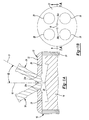
FIGS. 1A ,2A and3 , anengine 10 is provided and may include acylinder 12 and apiston 14. While only onecylinder 12 and onepiston 14 are shown, it will be appreciated that theengine 10 may include any number ofcylinders 12 andpistons 14, as is known in the art. - The
cylinder 12 may include acylinder block 20 and acylinder head 22. Thecylinder block 20 andcylinder head 22 may define achamber 24 having a central,longitudinal axis 18. Thepiston 14 may slide or otherwise move along thecentral axis 18 within thechamber 24 to drive a crankshaft (not shown) and provide power to theengine 10. Thecylinder head 22 may include at least oneintake valve assembly 26 and at least oneexhaust valve assembly 28. In one configuration, thecylinder head 22 includes twointake valve assemblies 26 and twoexhaust valve assemblies 28. Theintake valve assemblies 26 may deliver air from an intake source (not shown) to thechamber 24 while theexhaust valve assemblies 28 deliver combustion exhaust from thechamber 24 to an exhaust system (not shown). - At least one
bore 30a may be formed in thecylinder head 22 or thecylinder block 20. With reference toFIGS. 1A and 1B , in one configuration, thecylinder head 22 includes twobores 30a located proximate to thecentral axis 18, and generally central to theintake valve assemblies 26 and theexhaust valve assemblies 28. Alongitudinal axis 31 of one of thebores 30a may be disposed at an angle (α) relative to thecentral axis 18. - With reference to
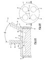
FIGS. 2A and 2B , in another configuration, thecylinder head 22 includes twobores 30b. At least one of thebores 30b may be substantially aligned with thecentral axis 18, while another of thebores 30b may be disposed substantially adjacent to and between theintake valve assemblies 26. Accordingly, alongitudinal axis 33 of one of thebores 30b may be disposed at an angle (β) relative to thecentral axis 18. - The
cylinder 12 may further include at least onefuel injector 34. Thefuel injector 34 may be a high-pressure fuel injector that injects natural gas into thechamber 24 of thecylinder 12. While thefuel injector 34 is described as injecting natural gas, thefuel injector 34 may inject any other suitable fuel into thechamber 24. - With reference to
FIGS. 1A and2A , thefuel injector 34 may be disposed in one of thebores diesel injector 36, a spark plug (not shown), or another suitable device (e.g., a micro-pilot) for igniting the fuel supplied by thefuel injector 34 may be disposed in theother bore - With reference to
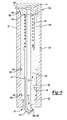
FIG. 3 , in another configuration, thefuel injector 34 may be disposed within anintake port 38 of anengine 10. Theintake port 38 may be in fluid communication with at least oneintake valve assembly 26. Accordingly, thefuel injector 34 may deliver fuel to thechamber 24 via theintake port 38. - With reference to
FIGS. 4A and4B , thefuel injector 34 will now be described in detail. Thefuel injector 34 may include aninjector body 40, a needle orinjector valve 42, a biasingmember 44, and acontrol valve assembly 46. Theinjector body 40 may include abase portion 48 and atip portion 50. In one configuration, thebase 48 and thetip 50 may define aninner chamber 53. Thetip 50 may be fastened to the base 48 using a threaded configuration, a press-fit configuration, or by using other suitable mechanical fastening techniques. Alternatively, thetip 50 may be integrally formed with the base 48 in a monolithic construct. - The base 48 may extend from a
proximal end 52 to adistal end 54 along alongitudinal axis 56. Thedistal end 54 may form anannular shoulder 58 extending between and connecting thebase 48 and thetip 50. In this regard, thebase 48 may be a generally cylindrical construct having a diameter D1, and thetip 50 may be a generally cylindrical construct having a diameter D2 (FIG. 4A ). The diameter D1 may be larger than the diameter D2. In an assembled configuration,injector body 40 may be disposed within the bore 30 such that theshoulder 58 is disposed against a portion of thecylinder head 22 or a portion of theintake port 38. In one configuration, theinjector 34 may include agasket 59 or similar sealing feature disposed between theshoulder 58 and thecylinder head 22 to provide a sealed interface between theinjector body 40 and thecylinder head 22. - The
tip 50 may extend from aproximal end 60, adjacent thedistal end 54 of thebase 48, to adistal end 62 along thelongitudinal axis 56. Thedistal end 62 of thetip 50 may be generally conically shaped. Thetip 50 may include between two (2) and twelve (12) apertures orfuel injection ports 64 that provide fluid communication with thechamber 53. It will be appreciated that the number and configuration of thefuel injection ports 64 may vary depending on the particular use or application of thefuel injector 34. - The
chamber 53 may extend along thelongitudinal axis 56 and may include afirst portion 66 and asecond portion 68. An annular flange orshoulder 70 may extend between and connect thefirst portion 66 and thesecond portion 68. In this regard, thefirst portion 66 may be a generally cylindrical chamber having a diameter D3, and thesecond portion 68 may be a cylindrical chamber having a diameter D4 (FIG. 4A ). The diameter D3 may be larger than the diameter D4. The conical configuration of thedistal end 62 of thetip 50 may generally define a conical configuration at adistal end 71 of thechamber 53 thereof. - The
injector 34 may further include afirst intake port 74 and asecond intake port 76. Thefirst intake port 74 may be disposed in thecontrol valve assembly 46 and may be in fluid communication with thefirst portion 66 of thechamber 53. Thefirst intake port 74 may be a high-pressure oil supply port or, alternatively, may supply any suitable fluid to thefirst portion 66 of thechamber 53. - The
second intake port 76 may extend through theinjector body 40 and may be in fluid communication with thesecond portion 68 of thechamber 53. In one configuration, thesecond intake port 76 may be an aperture formed through a sidewall of thebase 48. Thesecond intake port 76 may be a high-pressure natural gas port or, alternatively, may supply any suitable fluid to thesecond portion 68 of thechamber 53. - The
injector valve 42 may be located within thechamber 53 of theinjector body 40 and translates within thechamber 53 in a direction substantially parallel to thelongitudinal axis 56. Theinjector valve 42 may extend from aproximal end 78 to adistal end 80 along thelongitudinal axis 56. Theinjector valve 42 may include first, second andthird stem portions tip portion 88. An annular flange orshoulder 83 may extend radially outward from theinjector valve 42 between thefirst stem portion 86a and thesecond stem portion 86b. In one configuration, theshoulder 83 may be generally conically shaped. Alongitudinally extending bore 84 may extend at least partially through the first, second andthird stem portions tip portion 88, such that at least a portion of theinjector valve 42 is a generally hollow construct. - The
second stem portion 86b may be separated from thethird stem portion 86c by anannular shoulder 94. In this regard, thesecond stem portion 86b may be a generally cylindrical construct having a diameter D5, and thethird stem portion 86c may be a cylindrical construct having a diameter D6 (FIG. 4A ). The diameter D5 may be larger than the diameter D6 and may be substantially equal to the diameter D4 of thesecond portion 68 of thechamber 53. Accordingly, thesecond stem portion 86b of theinjector valve 42 may be sealingly disposed within thesecond portion 68 of thechamber 53 such that theinjector valve 42 prevents fluid communication between first andsecond portions chamber 53, and thereby prevents fluid communication between the first andsecond intake ports injector 34 may include an annular space or gap between thethird stem portion 86c and theinjector body 40 at thesecond portion 68 of thechamber 53. - The
tip portion 88 of theinjector valve 42 may extend from thethird stem portion 86c and may include a conically shapedsurface 96, such that thetip portion 88 is receivable within the conically shapeddistal end 71 of thechamber 53. Thetip portion 88 may further include a radially extendingflanged portion 98 having a firstannular surface 100 and a secondannular surface 102. The secondannular surface 102 may be substantially frustoconically shaped. - In a seated configuration, the second
annular surface 102 of theflanged portion 98 may be adjacent to, and sealingly engaged with, thetip 50 of theinjector body 40. Theflanged portion 98 may define a conically shaped space orgap 104 between thetip 50 of the injector body and thetip portion 88 of theinjector valve 42. In the seated configuration, thefuel injection ports 64 may be in fluid communication with thegap 104. In addition, in the seated configuration, theflanged portion 98 may prevent thefuel injection ports 64 from fluidly communicating with thesecond portion 68 of thechamber 53 and with thesecond intake port 76. Thegap 104 ensures that thetip portion 88 of theinjector valve 42 does not contact thefuel injection ports 64, which can help ensure that contaminant build-up or surface abnormalities on thetip portion 88 do not affect the performance of theinjection ports 64. Accordingly, theflanged portion 98 and thegap 104 may ensure better sealing of theinjection ports 64 when theinjector valve 42 is in the seated configuration (FIG. 4A ) and may provide better flow characteristics between theinjection ports 64 and thesecond portion 68 of thechamber 53 wheninjector valve 42 is in an unseated configuration (FIG. 4B ) - The biasing
member 44 may be located in thefirst portion 66 of thechamber 53. In one configuration, the biasingmember 44 is a helical spring concentrically disposed about thefirst stem portion 86a of theinjector valve 42, such that thefirst stem portion 86a axially supports the biasingmember 44. The biasingmember 44 may include afirst end 106 disposed adjacent thecontrol valve assembly 46 and asecond end 108 disposed adjacent theshoulder 83. In this way, the biasingmember 44 biases theinjector valve 42 along thelongitudinal axis 56 such that theflange portion 98 of theinjector valve 42 is sealingly engaged with thetip 50 of theinjector body 40, as previously described. - The
control valve assembly 46 may prevent fluid communication between thefirst intake port 74 and thefirst portion 66 of thechamber 53 in a first configuration (FIG. 4A ) and may allow fluid communication between thefirst intake port 74 and thefirst portion 66 of thechamber 53 in a second configuration (FIG. 4B ). - With reference to
FIG. 5 , anotherfuel injector 134 is provided. Thefuel injector 134 may include aninjector body 140, a needle orinjector valve 142, a biasingmember 144, and acontrol valve assembly 146. In view of the substantial similarity in structure and function of the components associated with thefuel injector 34 with thefuel injector 134, like reference numerals are used hereinafter to identify like components while like reference numerals having one hundred (100) added to the number of the corresponding element of thefuel injector 34 are used to identify those components that have been modified. - The
fuel injector 134 may generally be integrated with thecylinder head 22. The outer surface of theinjector body 140 may include at least oneannular channel 148. In one configuration, theinjector body 140 includes twochannels 148. It will appreciated, however, that the injector body may include less or more than twochannels 148 within the scope of the present teachings. An O-ring 150 or other suitable sealing feature may be disposed within each of thechannels 148 to seal a junction of theinjector body 140 and thecylinder head 22. - The
cylinder head 22 may include athird intake port 154 and afourth intake port 156. Thefuel injector 134 may be disposed within one of thebores cylinder head 22 such that the O-rings 150 or other suitable seals provide a sealed interface between thecylinder head 22 and theinjector body 140. In an assembled configuration, thethird intake port 154 of thecylinder head 22 may be in fluid communication with thefirst intake port 174, and thefourth intake port 156 may be in fluid communication with thesecond intake port 176 in theinjector body 140. In the assembled configuration, at least one of the O-rings 150 may prevent fluid communication between thethird intake port 154 and thefourth intake port 156. - With reference to
FIG. 6A , a fuelpressure regulating system 200, including another configuration of afuel injector 234, is shown. The fuelpressure regulating system 200 may include theinjector 234, anoil pump 236, a first fuel tank 238 (e.g., a liquid natural gas tank), a fuel pump 240 (e.g., a liquid natural gas pump), a second fuel tank 242 (e.g., a compressed natural gas pump), afuel pressure regulator 244, and apressure relief valve 246. - The
injector 234 may be substantially similar to thefuel injectors fuel injector 34 are used to identify those components that have been modified. - The
injector 234 may include anaccumulator 250. As illustrated, theaccumulator 250 may include an axially extending flange orwall 252 extending from adistal end 254 of thebase portion 248 of theinjector 234. In this regard, thewall 252 may define achamber 256. In an assembled configuration, thewall 252 may be coupled to aproximal end 258 of aninjector body 260, such that thechamber 256 may be in fluid communication with asecond intake port 261 and with thesecond portion 68 of thechamber 53. In one configuration, thewall 252 may be substantially cylindrical such that thechamber 256 annularly surrounds, and is concentrically located relative to, theinjector valve 42. Thewall 252 may have an inner diameter D7 that is greater than the diameter D4 of thesecond portion 68 of thechamber 53 and is greater than the diameter D5 ofsecond stem portion 86b of theinjector valve 42. - In the assembled configuration, the diameter D7 of the
chamber 256 may define an accumulator volume that is larger than a volume that would otherwise be defined by the diameter D4 of thesecond portion 68 of the chamber 53 (Figure 4A ). As will be explained in more detail below, theaccumulator 250, including the accumulator volume of thechamber 256, may allow theinjector 234 to deliver fuel through theinjection ports 64 and into thechamber 24 of thecylinder 12 in a very short period of time. For example, theaccumulator 250 may allow theinjector 234 to deliver fuel to thechamber 24 in approximately thirty (30) crank degrees, such that, of the seven hundred twenty (720) crank degrees in a four-cycle engine, one hundred percent (100%) of the fuel may be delivered in four percent (4%) of the total cycle time. Placing theaccumulator 250, including thechamber 256 directly in line with, and concentric to, theinjector valve 42 and thesecond portion 68 of thechamber 53, can help to avoid line losses and other inefficiencies during operation of theinjector 234. - The
pressure relief valve 246 may include ahousing 262, avalve member 264, and a biasingmember 265. Thehousing 262 may define aninner chamber 266, and may include afirst inlet port 268, asecond inlet port 270, afirst outlet port 272, and asecond outlet port 274. Thefirst inlet port 268 may be an oil inlet port in fluid communication with thechamber 266 and with theoil pump 236. Thesecond inlet port 270 may be a compressed natural gas port in fluid communication with thechamber 266 and with thefuel pressure regulator 244. Thefirst outlet port 272 may be a compressed natural gas port in fluid communication with thesecond intake port 261 of thefuel injector 234. Thesecond outlet port 274 may be a compressed natural gas port in fluid communication with thefirst fuel tank 238. - The
valve member 264 may be disposed within thechamber 266 of thehousing 262 and may include abody portion 276 and astem portion 278. In an assembled configuration, thebody portion 276 may sealingly engage aninner surface 280 of thehousing 262, such that thebody portion 276 divides thechamber 266 into afirst portion 266a and asecond portion 266b. As illustrated, thefirst inlet port 268 may be in fluid communication with thefirst portion 266a of thechamber 266, while thesecond inlet port 270 and the first andsecond outlet ports second portion 266b of thechamber 266. - The
stem portion 278 of thevalve member 264 may extend from thebody portion 276. In an assembled configuration, thestem portion 278 may be aligned with thesecond outlet port 274, such that thestem portion 278 prevents fluid communication between thesecond portion 266b of thechamber 266 andsecond outlet port 274, as will be described in more detail below. - The biasing
member 265 may be disposed within thechamber 266 and may be a helical spring disposed between thehousing 262 and thevalve member 264. The biasingmember 265 biases thestem portion 278 away from thesecond outlet port 274, to allow fluid communication between thesecond outlet port 274 and thesecond portion 266b of thechamber 266. - A first flow path 282 (e.g., a first conduit) may extend from and between the
oil pump 236, thefirst inlet port 268, and thefirst intake port 74. Accordingly, thefirst flow path 282 may allow theoil pump 236 to fluidly communicate with both thefirst intake port 74 of theinjector 234 and with thefirst inlet port 268 of thepressure relief valve 246. - A second flow path 284 (e.g., a second conduit) may extend from and between the
second inlet port 270 and thesecond outlet port 274. Thesecond flow path 284 may include thefirst fuel tank 238, thefuel pump 240, thesecond fuel tank 242, and thefuel pressure regulator 244. Accordingly, and as will be described in more detail below, thesecond flow path 284 allows thesecond inlet port 270 to fluidly communicate with thesecond outlet port 274. - A third flow path 286 (e.g., a third conduit) may extend from and between the
first outlet port 272 and thesecond intake port 261 of thefuel injector 234. Accordingly, thethird flow path 286 allows thefirst outlet port 272 to fluidly communicate with thesecond intake port 261. - With reference to
FIG. 6B , another configuration of a fuelpressure regulating system 300 is shown. The fuelpressure regulating system 300 is substantially identical to the fuelpressure regulating system 200, except as described below. Accordingly, like reference numerals are used to describe like features and components. Similar features will not be described again in detail. - The fuel
pressure regulating system 300 may include theinjector 234, theoil pump 236, thefirst fuel tank 238, thefuel pump 240, thesecond fuel tank 242, thefuel pressure regulator 244, and apressure relief valve 246a. Athird flow path 286a (e.g., a third conduit) may extend from and between thesecond flow path 284 and thesecond intake port 261 of theinjector 234. Accordingly, thethird flow path 286a may allow thesecond outlet port 274 to fluidly communicate with thesecond intake port 261. - With reference to
FIG. 7 , a fuelpressure regulating system 400, including another configuration of afuel injector 434, is shown. The fuelpressure regulating system 400 may include theinjector 434, theoil pump 236, thefirst fuel tank 238, thefuel pump 240, thesecond fuel tank 242, thefuel pressure regulator 244, and thepressure relief valve 246. - The
injector 434 may be substantially similar to thefuel injectors fuel injector 34 are used to identify those components that have been modified. - The
injector 434 may include aninjector body 440, aninjector valve 442, and a biasingmember 444. Theinjector valve 442 may extend from aproximal end 478 to adistal end 480 along thelongitudinal axis 56. Afirst stem portion 486a of theinjector valve 442 may include abore 484 extending from an annular flange orshoulder 483 to theproximal end 478 of theinjector valve 442. Thefirst stem portion 486a of theinjector valve 442 may disposed within thefirst portion 466 of thechamber 453, such that thefirst stem portion 486a, including theshoulder 483, separates aproximal end 491 of thefirst portion 466 from adistal end 493 of thefirst portion 466. Theshoulder 483 may include a through hole oraperture 490 in fluid communication with the proximal anddistal ends chamber 453. Thefirst stem portion 486a may be sealingly disposed within thefirst portion 466 of thechamber 453, such that thefirst stem portion 486a prevents theproximal portion 491 of thechamber 453 from fluidly communicating with thedistal portion 493 of thechamber 453, other than through theaperture 490. - The biasing
member 44 may be located within thebore 484. In one configuration, the biasingmember 44 is concentrically disposed within thebore 484 of thefirst stem portion 486a, such that thesecond end 108 of the biasingmember 44 engages theshoulder 483. In this way, the biasingmember 44 biases theinjector valve 442 along thelongitudinal axis 56. - Operation of the
fuel injectors FIGS. 4A-7 . Operation of the fuel injectors will be described relative to a force F1 applied by the biasingmember intake port intake port fuel injectors cylinder block 20, thecylinder head 22, or theintake port 38 such that thefuel injection ports 64 fluidly communicate with thechamber 24. - With reference to
FIG. 4A , in a first mode of operation, thecontrol valve assembly 46 may be in a closed configuration, thereby preventing fluid communication between thefirst intake port 74 and thefirst portion 66 of thechamber 53. In the first mode of operation, the biasingmember 44 may apply the force F1 on theinjector valve 42. However, in contrast toFIG. 4A , in the first mode of operation a high pressure fluid (e.g., engine oil from a motor vehicle) may not apply the force F3 on theproximal end 78 of theinjector valve 42. Thus, by applying the force F1 in the first mode of operation, the biasingmember 44 biases thetip portion 88 into engagement with thetip 50 of theinjector body 40, such that the secondannular surface 102 prevents fluid communication between thefuel injection ports 64 and thesecond intake port 76. In this way, the biasingmember 44 may act as a fail-safe mechanism to prevent fluid communication between thefuel injection ports 64 and thechamber 24 when thecontrol valve assembly 46 is in the closed configuration and high-pressure fluid is not supplied to the first intake port 74 (e.g., when engine power is turned off). - With continued reference to
FIG. 4A , in a second mode of operation, thecontrol valve assembly 46 may be in an open configuration, thereby allowing fluid communication between thefirst intake port 74 and thefirst portion 66 of thechamber 53. In the second mode of operation, the biasingmember 44 may apply the force F1 on theinjector valve 42, and a high-pressure fluid (e.g., engine oil from a motor vehicle) may apply the force F3 on theproximal end 78 of theinjector valve 42, to bias thetip portion 88 into engagement with thetip 50 of theinjector body 40, such that the secondannular surface 102 prevents fluid communication between thefuel injection ports 64 and thesecond intake port 76. - By injecting oil through the
first intake port 74, proper lubrication of thecontrol valve assembly 46 and cooling of theinjector valve 42 and theinjector body 40 may be ensured. In the second mode of operation, high-pressure gas, or other suitable fluid, may be supplied to thesecond portion 68 of thechamber 53 and/or to thechamber 256 of the accumulator 250 (FIG. 6A ), respectively, as described above. The force F3 may be substantially opposite, and greater than, the force F2 provided by the high-pressure gas. - With reference to
FIG. 4B , in a third mode of operation, thecontrol valve assembly 46 may be in a closed configuration, thereby preventing fluid communication between thefirst intake port 74 and thefirst portion 66 of thechamber 53. High-pressure gas, or other suitable fluid, may be supplied from thesecond intake port second portion 68 of thechamber 53 and/or to thechamber 256 of theaccumulator 250, respectively. The high-pressure gas may fill the annular gap between theinjector valve 42 and theinjector body 40 and may apply the force F2 on theshoulder 94 of theinjector valve 42 to bias thetip portion 88 away from thetip 50 of theinjector body 40, such that thefuel injection ports 64 are placed in fluid communication with thesecond portion 68 of thechamber 53 and with thesecond intake port 76. Accordingly, the force F2 may be substantially opposite, and greater than, the force F1 provided by the biasingmember 44. - With reference to
FIG. 6A , operation of the fuelpressure regulating system 200, including thefuel injector 234 and thepressure relief valve 246, will now be described in more detail. During operation of the fuelpressure regulating system 200, high-pressure oil may be supplied, or otherwise transported, through thefirst flow path 282. Specifically, high-pressure oil from theoil pump 236 may be supplied to thefirst intake port 74 of thefuel injector 234 and to thefirst inlet port 268 of thepressure relief valve 246. In this regard, operation of thefuel injector 234 may be substantially similar to operation of thefuel injectors - The high-pressure oil supplied to the
first inlet port 268 of thepressure relief valve 246 and, thus, to thefirst portion 266a of thechamber 266, may apply a force on thevalve member 264 that is opposite, and greater than, a force applied on thevalve member 264 by the biasingmember 265. In this way, the high-pressure oil may bias thestem portion 278 of thevalve member 264 into a closed position relative to thesecond outlet port 274, such that thevalve member 264 prevents fluid communication between thesecond outlet port 274 and thesecond portion 266b of thechamber 266. - Natural gas may be supplied or otherwise transported through the
second flow path 284. Specifically, natural gas from thefirst fuel tank 238 may first be supplied to thesecond fuel tank 242 by thefuel pump 240. The natural gas may further be supplied or transported from thesecond fuel tank 242 to thefuel pressure regulator 244, and from thefuel pressure regulator 244 to thesecond inlet port 270 of thepressure relief valve 246. - The fuel
pressure regulating system 200 may further include a controller 298 (e.g., an engine control unit). Thecontroller 298 may be in communication with theoil pump 236, thefuel pump 240, thefuel pressure regulator 244, and/or with theinjector 234, to control various characteristics (e.g., pressure, quantity, and duration) of the supply of oil and natural gas to the first andsecond inlet ports first inlet port 268 of thepressure relief valve 246 is terminated or otherwise reduced below a predetermined level, the force of the biasingmember 265 and/or a force created on thevalve member 264 by the natural gas within thesecond portion 266b of thechamber 266 may urge thestem portion 278 of thevalve member 264 away from thesecond outlet port 274, such that the second outlet port is in fluid communication with thesecond portion 266b of thechamber 266. In this way, thepressure relief valve 246 can operate as a fail-safe mechanism, allowing for the movement of natural gas from thefuel pressure regulator 244 to thefirst fuel tank 238, when natural gas is supplied to thesecond inlet port 270 and oil is not supplied, or is otherwise supplied at a pressure that is lower than a predetermined value, to thefirst inlet port 268. - With reference to
FIG. 6B , operation of the fuelpressure regulating system 300, including thefuel injector 234 and thepressure relief valve 246a, will now be described in more detail. Operation of the fuelpressure regulating system 300 may be substantially similar to operation of the fuelpressure regulating system 200, except as otherwise described herein. - Natural gas may be supplied or transported from the
second flow path 284 to thesecond intake port 261 of theinjector 234 and to thesecond portion 266b of the ofchamber 266 of thepressure relief valve 246a. Specifically, the natural gas may be transported from thefirst fuel tank 238 to thesecond fuel tank 242, from thesecond fuel tank 242 to thefuel pressure regulator 244, and from thefuel pressure regulator 244 to thethird flow path 286a, prior to entering thesecond intake port 261 of theinjector 234 and thesecond inlet port 270 of thepressure relief valve 246a. - If the supply of high-pressure oil to the
first inlet port 268 of thepressure relief valve 246a is terminated or otherwise reduced below a predetermined level, the force of the biasingmember 265 and/or a force created on thevalve member 264 by the natural gas within thesecond portion 266b of thechamber 266 may urge thestem portion 278 of thevalve member 264 away from thesecond outlet port 274, such that the second outlet port is in fluid communication with thesecond portion 266b of thechamber 266. In this way, thepressure relief valve 246a can operate as a fail-safe mechanism, allowing for the movement of natural gas from thefuel pressure regulator 244 to thefirst fuel tank 238, when natural gas is supplied to thesecond inlet port 270 and oil is not supplied, or is otherwise supplied at a pressure that is lower than a predetermined value, to thefirst inlet port 268. - With reference to
FIG. 7 , operation of the fuelpressure regulating system 400, including thefuel injector 434 will now be described in more detail. Operation of the fuelpressure regulating system 400 and thefuel injector 434 may be substantially similar to the operation of the fuelpressure regulating systems fuel injectors pressure regulating system 400, high-pressure oil may be supplied, or otherwise transported, through thefirst flow path 282. Specifically, high-pressure oil from theoil pump 236 may be supplied to thefirst intake port 74 of thefuel injector 434. - In a third mode of operation, the
control valve assembly 46 may be in an open configuration and high-pressure oil (e.g., engine oil from a motor vehicle), or other suitable fluid, may be supplied to theproximal end 491 of thechamber 453 from thefirst intake port 74. The high-pressure oil may then flow into thebore 484 of theinjector valve 442 and apply the force F3 on theshoulder 483 of theinjector valve 442. Accordingly, the high-pressure oil will bias and translate thetip portion 488 of theinjector valve 442 into engagement with the tip 450 of theinjector body 440, such that theflanged portion 498 prevents fluid communication between thefuel injection ports 64 and thesecond intake port 261. During translation of theinjector valve 442 from the open position (e.g.,FIG. 4B ) to the closed position illustrated inFIG. 7 , the high-pressure oil supplied to thebore 484 may flow through theaperture 490 and into thedistal end 493 of thechamber 453. The high-pressure oil flowing into thedistal end 493 of thechamber 453 may apply a force F4 on theshoulder 483 of theinjector valve 442. The force F4 may be opposite the force F3, such that the high-pressure oil and the force F4 act to dampen or otherwise slow the movement of theinjector valve 442 relative to theinjector body 440. - The foregoing description of the embodiments has been provided for purposes of illustration and description. It is not intended to be exhaustive or to limit the disclosure. Individual elements or features of a particular embodiment are generally not limited to that particular embodiment, but, where applicable, are interchangeable and can be used in a selected embodiment, even if not specifically shown or described. The same may also be varied in many ways. Such variations are not to be regarded as a departure from the disclosure, and all such modifications are intended to be included within the scope of the disclosure.
Claims (15)
- A fuel injector (34) comprising:an injector body (40) defining a longitudinally extending chamber (53), the injector body (40) having a first intake port (74), a second intake port (76) and a fuel injection port (64); andan injector valve (42) disposed within the longitudinally extending chamber (53), the injector valve (42) including a longitudinally extending aperture (84) in fluid communication with the longitudinally extending chamber (53), the injector valve (42) configured to prevent fluid communication between the first intake port (74) and the second intake port (76), and configured to prevent fluid communication between the fuel injection port (64) and the second intake port (76).
- The fuel injector (34) of Claim 1, further comprising a biasing member (44) disposed within the longitudinally extending chamber (53), wherein the biasing member (44) is configured to bias the injector valve (42) into engagement with the injector body (40).
- The fuel injector (34) of Claim 1 or 2, further comprising a biasing member (44) disposed within the longitudinally extending chamber (53), wherein the biasing member (44) is configured to bias the injector valve (42) into engagement with the injector body (40) to prevent fluid communication between the fuel injection port (64) and the second intake port (76).
- The fuel injector (34) of any of the preceding claims, wherein the injector valve (42) includes an annular flanged portion (98), and wherein the annular flanged portion (98) is operable to engage the injector body (40) to define a gap (104) between the injector valve (42) and the injector body (40).
- The fuel injector (34) of any of the preceding claims, wherein the injector valve (42) is moveable between a first position in which the injector valve (42) prevents fluid communication between the fuel injection port (64) and the second intake port (76), and a second position in which the injector valve (42) allows fluid communication between the fuel injection port (64) and the second intake port (76).
- The fuel injector (34) of Claim 5, further comprising a control valve (46), wherein the control valve (46) is operable to allow fluid flow through the first intake port (74) to prevent fluid communication between the fuel injection port (64) and the second intake port (76).
- The fuel injector of Claim 6, wherein the control valve (46) is operable to allow fluid flow between the first intake port (74) and the longitudinally extending chamber (53) to move the injector valve (42) to the first position and thereby prevent fluid communication between the fuel injection port (64) and the second intake port (76).
- The fuel injector (34) of any of the preceding claims, wherein the first intake port (74) is an oil intake port and the second intake port (76) is a natural gas intake port.
- The fuel injector (34) of any of the preceding claims, wherein the injector valve (42) includes an annular shoulder (483) having an aperture (490), the aperture (490) in fluid communication with the longitudinally extending aperture (484) and a first portion of the longitudinally extending chamber (53).
- The fuel injector (34) of any of the preceding claims, wherein the chamber (53) includes first and second portions (66, 68) at least partially defined by the injector valve (42) and the injector body (40), the injector valve (42) preventing fluid communication between the first and second portions (66, 68).
- The fuel injector (34) of any of the preceding claims, wherein the injector body (40) includes a conically shaped end portion (62).
- The fuel injector (34) of Claim 11, wherein the injector valve (42) includes a conically shaped tip portion (88) disposed within the end portion (62).
- The fuel injector (34) of Claim 12, wherein the tip portion (88) includes an annular flanged portion (98) operable to engage the end portion (62).
- A fuel injector (34) comprising:an injector body (40) defining a longitudinally extending chamber (53), the injector body (40) having a first intake port (74), a second intake port (76) and a fuel injection port (64), the first intake port (74) configured to deliver a first fluid into the chamber (53) to apply a first force, the second intake port (76) configured to deliver a second fluid into the longitudinally extending chamber (53) to apply a second force, the second force opposing the first force; andan injector valve (42) disposed within the longitudinally extending chamber (53) and configured to prevent fluid communication between the first intake port (74) and the second intake port (76), the injector valve (42) including a longitudinally extending aperture (84) in fluid communication with the longitudinally extending chamber (53).
- The fuel injector (34) of Claim 14, further comprising a biasing member (44) disposed within the longitudinally extending chamber (53), wherein the biasing member (44) is configured to apply a biasing force to the injector valve (42) in the first direction to bias the injector valve (42) into engagement with the injector body (40).
Applications Claiming Priority (2)
| Application Number | Priority Date | Filing Date | Title |
|---|---|---|---|
| US201462005342P | 2014-05-30 | 2014-05-30 | |
| US14/704,144 US9856841B2 (en) | 2014-05-30 | 2015-05-05 | Fuel injector |
Publications (1)
| Publication Number | Publication Date |
|---|---|
| EP2949916A1 true EP2949916A1 (en) | 2015-12-02 |
Family
ID=53268645
Family Applications (1)
| Application Number | Title | Priority Date | Filing Date |
|---|---|---|---|
| EP15168422.2A Withdrawn EP2949916A1 (en) | 2014-05-30 | 2015-05-20 | Fuel injector |
Country Status (2)
| Country | Link |
|---|---|
| US (1) | US9856841B2 (en) |
| EP (1) | EP2949916A1 (en) |
Cited By (3)
| Publication number | Priority date | Publication date | Assignee | Title |
|---|---|---|---|---|
| WO2019072562A1 (en) * | 2017-10-10 | 2019-04-18 | Robert Bosch Gmbh | Injector for metering a fluid under high pressure and method for operating such an injector |
| WO2019145592A1 (en) * | 2018-01-23 | 2019-08-01 | Wärtsilä Finland Oy | Fuel injection arrangement and method of operating piston engine |
| DE102021206997A1 (en) | 2021-07-05 | 2023-01-05 | Robert Bosch Gesellschaft mit beschränkter Haftung | Injector and arrangement with an injector |
Families Citing this family (2)
| Publication number | Priority date | Publication date | Assignee | Title |
|---|---|---|---|---|
| DE102014224356A1 (en) * | 2014-11-28 | 2016-06-02 | Robert Bosch Gmbh | Gas injector with Hubentdrosselung |
| CN114251210B (en) * | 2022-03-01 | 2022-06-24 | 潍柴动力股份有限公司 | Parameter calibration method of oil injection device |
Citations (9)
| Publication number | Priority date | Publication date | Assignee | Title |
|---|---|---|---|---|
| US4687136A (en) * | 1985-02-15 | 1987-08-18 | Kawasaki Jukogyo Kabushiki Kaisha | Gas injection valve for gas engine |
| JPH10220227A (en) * | 1997-02-04 | 1998-08-18 | Kubota Corp | Fuel gas feeding device for spark ignition type gas engine |
| EP1067284A1 (en) * | 1999-07-03 | 2001-01-10 | Robert Bosch Gmbh | Fuel injection valve |
| US20090020631A1 (en) * | 2007-07-17 | 2009-01-22 | Denso Corporation | Gaseous fuel injector using liquid fuel as lubricant and pressure-transmitting medium |
| JP2010265855A (en) * | 2009-05-18 | 2010-11-25 | Nippon Soken Inc | Fuel injection device |
| US20130081593A1 (en) * | 2011-09-30 | 2013-04-04 | Caterpillar, Inc. | Single Actuator Fuel Injector for Dual Fuels |
| JP2013087727A (en) * | 2011-10-20 | 2013-05-13 | Toyota Motor Corp | Fuel injection device of internal combustion engine |
| US20130160741A1 (en) * | 2011-12-23 | 2013-06-27 | Caterpillar Inc. | Dual fuel injector having fuel leak seals |
| JP2014015918A (en) * | 2012-07-11 | 2014-01-30 | Denso Corp | Fuel injection system of internal combustion engine |
Family Cites Families (10)
| Publication number | Priority date | Publication date | Assignee | Title |
|---|---|---|---|---|
| FR2058548A5 (en) * | 1969-09-15 | 1971-05-28 | Crepelle & Cie | |
| US4986472A (en) * | 1989-09-05 | 1991-01-22 | Cummins Engine Company, Inc. | High pressure unit fuel injector with timing chamber pressure control |
| US5398875A (en) * | 1993-01-05 | 1995-03-21 | Sverdlin; Anatoly | Ternary phase, fluid controlled, differential injection pressure fuel element |
| FR2748783B1 (en) * | 1996-05-17 | 1998-08-14 | Melchior Jean F | LIQUID FUEL INJECTION DEVICE FOR INTERNAL COMBUSTION ENGINE |
| DE19821768C2 (en) * | 1998-05-14 | 2000-09-07 | Siemens Ag | Dosing device and dosing method |
| EP1335125B1 (en) * | 2000-11-17 | 2006-02-08 | Isuzu Motors Limited | Needle lift damper device of injector for fuel injection and needle lift damping method |
| US7028918B2 (en) | 2001-02-07 | 2006-04-18 | Cummins Engine Company, Inc. | Fuel injector having a nozzle with improved cooling |
| DE10141221B4 (en) * | 2001-08-23 | 2009-07-30 | Robert Bosch Gmbh | Pressure-stroke controlled injector for fuel injection systems |
| JP5304861B2 (en) * | 2010-12-17 | 2013-10-02 | 株式会社デンソー | Fuel injection device |
| CA2743043C (en) | 2011-06-14 | 2012-09-18 | Westport Power Inc. | Dual fuel injection valve |
-
2015
- 2015-05-05 US US14/704,144 patent/US9856841B2/en active Active
- 2015-05-20 EP EP15168422.2A patent/EP2949916A1/en not_active Withdrawn
Patent Citations (9)
| Publication number | Priority date | Publication date | Assignee | Title |
|---|---|---|---|---|
| US4687136A (en) * | 1985-02-15 | 1987-08-18 | Kawasaki Jukogyo Kabushiki Kaisha | Gas injection valve for gas engine |
| JPH10220227A (en) * | 1997-02-04 | 1998-08-18 | Kubota Corp | Fuel gas feeding device for spark ignition type gas engine |
| EP1067284A1 (en) * | 1999-07-03 | 2001-01-10 | Robert Bosch Gmbh | Fuel injection valve |
| US20090020631A1 (en) * | 2007-07-17 | 2009-01-22 | Denso Corporation | Gaseous fuel injector using liquid fuel as lubricant and pressure-transmitting medium |
| JP2010265855A (en) * | 2009-05-18 | 2010-11-25 | Nippon Soken Inc | Fuel injection device |
| US20130081593A1 (en) * | 2011-09-30 | 2013-04-04 | Caterpillar, Inc. | Single Actuator Fuel Injector for Dual Fuels |
| JP2013087727A (en) * | 2011-10-20 | 2013-05-13 | Toyota Motor Corp | Fuel injection device of internal combustion engine |
| US20130160741A1 (en) * | 2011-12-23 | 2013-06-27 | Caterpillar Inc. | Dual fuel injector having fuel leak seals |
| JP2014015918A (en) * | 2012-07-11 | 2014-01-30 | Denso Corp | Fuel injection system of internal combustion engine |
Cited By (5)
| Publication number | Priority date | Publication date | Assignee | Title |
|---|---|---|---|---|
| WO2019072562A1 (en) * | 2017-10-10 | 2019-04-18 | Robert Bosch Gmbh | Injector for metering a fluid under high pressure and method for operating such an injector |
| WO2019145592A1 (en) * | 2018-01-23 | 2019-08-01 | Wärtsilä Finland Oy | Fuel injection arrangement and method of operating piston engine |
| KR20200088496A (en) * | 2018-01-23 | 2020-07-22 | 바르실라 핀랜드 오이 | How to operate the fuel injection arrangement and piston engine |
| KR102189095B1 (en) | 2018-01-23 | 2020-12-11 | 바르실라 핀랜드 오이 | Fuel injection arrangement and how to operate a piston engine |
| DE102021206997A1 (en) | 2021-07-05 | 2023-01-05 | Robert Bosch Gesellschaft mit beschränkter Haftung | Injector and arrangement with an injector |
Also Published As
| Publication number | Publication date |
|---|---|
| US20150345454A1 (en) | 2015-12-03 |
| US9856841B2 (en) | 2018-01-02 |
Similar Documents
| Publication | Publication Date | Title |
|---|---|---|
| US9856841B2 (en) | Fuel injector | |
| JP6141328B2 (en) | Fuel injection valve and fuel injection device | |
| EP1707799A1 (en) | Fuel pump having plunger and fuel supply system using the same | |
| US20130302194A1 (en) | High-pressure pump | |
| US10473076B2 (en) | High pressure pump with pump spring sealing sleeve | |
| CN109154404B (en) | Pressure regulating module with controlled leakage path | |
| US11713755B2 (en) | High-pressure fuel pump | |
| US10995720B1 (en) | Fuel system having a connection between a fuel injector and a fuel distribution conduit | |
| CN100473821C (en) | Fuel pump having plunger and fuel supply system using the same | |
| US10584700B1 (en) | High-pressure fuel pump | |
| CN109642532B (en) | Relief valve device and high-pressure pump | |
| JP6083948B2 (en) | Fluid ejection device | |
| US20160061169A1 (en) | A fuel injection unit and fuel feeding arrangement | |
| CN107850010B (en) | Multi-plunger cryopump with intake manifold | |
| JP5370192B2 (en) | Fuel supply device | |
| EP2995806A1 (en) | Fuel injector with diesel pilot injection | |
| EP0097429A1 (en) | Fuel pump-injector unit | |
| CN111417775A (en) | Gas pressure regulator for regulating the pressure of a gaseous fuel, system for supplying an internal combustion engine with a gaseous fuel using such a gas pressure regulator, and method for operating such a system | |
| US11346313B2 (en) | Fuel flow limiter assembly having integral fuel filter and fuel system using same | |
| US11143154B2 (en) | Fuel system having a connection between a fuel injector and a fuel distribution conduit | |
| US10473073B2 (en) | Fuel injector having valve stack with vented back-up plate for check seal retention | |
| WO2020172011A1 (en) | Fuel injector assembly having external filter and method of making same |
Legal Events
| Date | Code | Title | Description |
|---|---|---|---|
| AK | Designated contracting states |
Kind code of ref document: A1 Designated state(s): AL AT BE BG CH CY CZ DE DK EE ES FI FR GB GR HR HU IE IS IT LI LT LU LV MC MK MT NL NO PL PT RO RS SE SI SK SM TR |
|
| AX | Request for extension of the european patent |
Extension state: BA ME |
|
| PUAI | Public reference made under article 153(3) epc to a published international application that has entered the european phase |
Free format text: ORIGINAL CODE: 0009012 |
|
| 17P | Request for examination filed |
Effective date: 20160602 |
|
| RBV | Designated contracting states (corrected) |
Designated state(s): AL AT BE BG CH CY CZ DE DK EE ES FI FR GB GR HR HU IE IS IT LI LT LU LV MC MK MT NL NO PL PT RO RS SE SI SK SM TR |
|
| 17Q | First examination report despatched |
Effective date: 20170508 |
|
| STAA | Information on the status of an ep patent application or granted ep patent |
Free format text: STATUS: THE APPLICATION IS DEEMED TO BE WITHDRAWN |
|
| 18D | Application deemed to be withdrawn |
Effective date: 20180919 |