EP2949904B1 - Combustor and gas turbine - Google Patents
Combustor and gas turbine Download PDFInfo
- Publication number
- EP2949904B1 EP2949904B1 EP14762567.7A EP14762567A EP2949904B1 EP 2949904 B1 EP2949904 B1 EP 2949904B1 EP 14762567 A EP14762567 A EP 14762567A EP 2949904 B1 EP2949904 B1 EP 2949904B1
- Authority
- EP
- European Patent Office
- Prior art keywords
- combustor
- outer circumferential
- circumferential surface
- main body
- tube
- Prior art date
- Legal status (The legal status is an assumption and is not a legal conclusion. Google has not performed a legal analysis and makes no representation as to the accuracy of the status listed.)
- Active
Links
- 239000000446 fuel Substances 0.000 claims description 37
- 239000000567 combustion gas Substances 0.000 claims description 17
- 239000007789 gas Substances 0.000 claims description 17
- 230000007704 transition Effects 0.000 description 44
- 238000004519 manufacturing process Methods 0.000 description 10
- 238000011144 upstream manufacturing Methods 0.000 description 8
- 238000003754 machining Methods 0.000 description 7
- 125000006850 spacer group Chemical group 0.000 description 6
- 238000002485 combustion reaction Methods 0.000 description 5
- 230000000052 comparative effect Effects 0.000 description 5
- 239000010408 film Substances 0.000 description 4
- 238000001816 cooling Methods 0.000 description 2
- 238000009792 diffusion process Methods 0.000 description 2
- 238000000034 method Methods 0.000 description 2
- 238000003801 milling Methods 0.000 description 2
- 230000000644 propagated effect Effects 0.000 description 2
- 230000008878 coupling Effects 0.000 description 1
- 238000010168 coupling process Methods 0.000 description 1
- 238000005859 coupling reaction Methods 0.000 description 1
- 238000001514 detection method Methods 0.000 description 1
- 238000006073 displacement reaction Methods 0.000 description 1
- 230000000694 effects Effects 0.000 description 1
- 239000012530 fluid Substances 0.000 description 1
- 238000009434 installation Methods 0.000 description 1
- 238000007789 sealing Methods 0.000 description 1
- 239000010409 thin film Substances 0.000 description 1
Images


Classifications
-
- F—MECHANICAL ENGINEERING; LIGHTING; HEATING; WEAPONS; BLASTING
- F23—COMBUSTION APPARATUS; COMBUSTION PROCESSES
- F23R—GENERATING COMBUSTION PRODUCTS OF HIGH PRESSURE OR HIGH VELOCITY, e.g. GAS-TURBINE COMBUSTION CHAMBERS
- F23R3/00—Continuous combustion chambers using liquid or gaseous fuel
- F23R3/42—Continuous combustion chambers using liquid or gaseous fuel characterised by the arrangement or form of the flame tubes or combustion chambers
-
- F—MECHANICAL ENGINEERING; LIGHTING; HEATING; WEAPONS; BLASTING
- F01—MACHINES OR ENGINES IN GENERAL; ENGINE PLANTS IN GENERAL; STEAM ENGINES
- F01D—NON-POSITIVE DISPLACEMENT MACHINES OR ENGINES, e.g. STEAM TURBINES
- F01D9/00—Stators
- F01D9/02—Nozzles; Nozzle boxes; Stator blades; Guide conduits, e.g. individual nozzles
- F01D9/023—Transition ducts between combustor cans and first stage of the turbine in gas-turbine engines; their cooling or sealings
-
- F—MECHANICAL ENGINEERING; LIGHTING; HEATING; WEAPONS; BLASTING
- F02—COMBUSTION ENGINES; HOT-GAS OR COMBUSTION-PRODUCT ENGINE PLANTS
- F02C—GAS-TURBINE PLANTS; AIR INTAKES FOR JET-PROPULSION PLANTS; CONTROLLING FUEL SUPPLY IN AIR-BREATHING JET-PROPULSION PLANTS
- F02C3/00—Gas-turbine plants characterised by the use of combustion products as the working fluid
- F02C3/04—Gas-turbine plants characterised by the use of combustion products as the working fluid having a turbine driving a compressor
-
- F—MECHANICAL ENGINEERING; LIGHTING; HEATING; WEAPONS; BLASTING
- F23—COMBUSTION APPARATUS; COMBUSTION PROCESSES
- F23R—GENERATING COMBUSTION PRODUCTS OF HIGH PRESSURE OR HIGH VELOCITY, e.g. GAS-TURBINE COMBUSTION CHAMBERS
- F23R3/00—Continuous combustion chambers using liquid or gaseous fuel
- F23R3/42—Continuous combustion chambers using liquid or gaseous fuel characterised by the arrangement or form of the flame tubes or combustion chambers
- F23R3/46—Combustion chambers comprising an annular arrangement of several essentially tubular flame tubes within a common annular casing or within individual casings
-
- F—MECHANICAL ENGINEERING; LIGHTING; HEATING; WEAPONS; BLASTING
- F23—COMBUSTION APPARATUS; COMBUSTION PROCESSES
- F23R—GENERATING COMBUSTION PRODUCTS OF HIGH PRESSURE OR HIGH VELOCITY, e.g. GAS-TURBINE COMBUSTION CHAMBERS
- F23R3/00—Continuous combustion chambers using liquid or gaseous fuel
- F23R3/42—Continuous combustion chambers using liquid or gaseous fuel characterised by the arrangement or form of the flame tubes or combustion chambers
- F23R3/54—Reverse-flow combustion chambers
-
- F—MECHANICAL ENGINEERING; LIGHTING; HEATING; WEAPONS; BLASTING
- F23—COMBUSTION APPARATUS; COMBUSTION PROCESSES
- F23R—GENERATING COMBUSTION PRODUCTS OF HIGH PRESSURE OR HIGH VELOCITY, e.g. GAS-TURBINE COMBUSTION CHAMBERS
- F23R2900/00—Special features of, or arrangements for continuous combustion chambers; Combustion processes therefor
- F23R2900/00012—Details of sealing devices
Definitions
- the present invention relates to a combustor that bums fuel in compressed air to produce a combustion gas and a gas turbine having the same.
- a gas turbine is equipped with a compressor that produces compressed air, a combustor that bums fuel in the compressed air to produce a combustion gas, and a turbine that is rotatably driven by the combustion gas.
- the combustor has a combustor basket that supplies a fuel and air, and a transition piece in which flames are formed by the fuel and air supplied from the combustor basket and which produces the combustion gas (e.g., see JP 2003-13747 A ).
- a structure for supplying film air from a gap between a transition piece and an outlet outer ring constituting a distal end of a combustor basket in order to prevent an inner wall surface of the transition piece from being damaged by a combustion gas produced in the transition piece is known.
- spacers are attached to the outlet outer ring to secure the gap for supplying the film air.
- the plurality of spacers are attached to an outer circumferential surface of the outlet outer ring in a circumferential direction. As the spacers are in contact with an inner circumferential surface of the transition piece, the gap for supplying the film air is uniformly secured throughout the circumference.
- US 2004/0074236 A1 discloses a combustor with the features of the preamble portion of claim 1.
- the combustor has a circular fuel nozzle block inserted into a liner of a combustion chamber.
- a plurality of spacers formed as separate elements are provided in the circumferential direction on the inner surface of the liner to form a gap between the outer surface of the fuel nozzle block and the inner surface of the liner.
- US 6732528 B2 discloses a combustor having a tail cylinder fixed to an internal round cylinder inserted into the tail cylinder and with integral protrusions formed on a side surface of an opening section of the internal cylinder in a clearance maintaining section at the section of engagement between the tail cylinder and the internal cylinder.
- An object of the present invention is to provide a combustor capable of reducing manufacturing costs by reducing the number of components, and a gas turbine having the same.
- a combustor includes the features of claim 1.
- the main body and the protrusions are integrally formed at the ring part.
- the number of components can be reduced, and manufacturing costs of the combustor can be reduced.
- the outer circumferential surface of the main body being a workpiece is formed, the number of times the relative angle between the working tool and the workpiece is changed is reduced, and thus the machining man-hours can be reduced.
- the main body may include a polygonal ring part on which the protrusions are formed, and a restrictor part which is provided at a distal end side relative to the polygonal ring part and an outer circumferential surface of which is formed in a cylindrical shape at a radially outer circumferential side relative to an outer circumferential surface of the polygonal ring part.
- the restrictor part is formed in the cylindrical shape, a second gap between the outer circumferential surface of the restrictor part and the inner circumferential surface of the second tube is uniform. Thereby, air ejected from this gap can be uniformized in a circumferential direction.
- the protrusions may be formed in centers of outer circumferential planes of the polygonal ring part in a circumferential direction.
- the protrusions are formed using a working tool for forming the outer circumferential planes. Thereby, it is possible to form the high-precision protrusions in which a radial thickness is uniform and a circumferential surface is wide in the radial direction.
- the protrusions when viewed in a radial direction along a radius of the first tube, may have a spindle cross-sectional shape along the axial direction.
- the present invention provides a gas turbine that includes: any of the above combustors; and a turbine driven by a combustion gas delivered from the second tube of the combustor.
- the gas turbine is equipped with the combustor, the number of components can be reduced, and the manufacturing costs of the combustor can be reduced.
- the main body and the protrusions are integrally formed at the ring part.
- the number of components can be reduced, and manufacturing costs of the combustor can be reduced.
- the outer circumferential surface of the main body being a workpiece is formed, the number of times the relative angle between the working tool and the workpiece is changed is reduced, and thus the machining man-hours can be reduced.
- a gas turbine GT of the present embodiment is equipped with a compressor 1 that produces compressed air, a combustor 3 that burns fuel in the compressed air to produce a combustion gas, and a turbine 5 that is rotatably driven by the combustion gas.
- the turbine 5 has a turbine casing 6 in which a casing 7 is formed, and a turbine rotor 8 that is rotatably installed in the casing 7.
- the compressor 1 takes in open air from its air intake 2 and compresses the open air, thereby producing the compressed air.
- the combustor 3 mixes fuel with the compressed air from the compressor 1 and burns the fuel.
- a high-temperature high-pressure combustion gas produced by the combustion of the fuel rotatably drives the turbine rotor 8.
- the combustor 3 has a fuel supplier 10 that injects the compressed air A from the compressor 1 (see Fig. 1 ) and the fuel, a combustor basket (first tube) 20 that supplies the compressed air A and the fuel from the fuel supplier 10, a transition piece (second tube) 30 that produces a combustion gas G from the compressed air A and the fuel supplied from the combustor basket 20 and sends the produced combustion gas G to the turbine 5.
- a fuel supplier 10 that injects the compressed air A from the compressor 1 (see Fig. 1 ) and the fuel
- a combustor basket (first tube) 20 that supplies the compressed air A and the fuel from the fuel supplier 10
- a transition piece (second tube) 30 that produces a combustion gas G from the compressed air A and the fuel supplied from the combustor basket 20 and sends the produced combustion gas G to the turbine 5.
- Both the combustor basket 20 and the transition piece 30 of the combustor 3 are disposed inside the casing 7 of the turbine 5.
- the fuel supplier 10 is equipped with a pilot burner 11 that supplies the compressed air A from the compressor 1 and a pilot fuel, and a plurality of nozzles 12 that premixes the compressed air A from the compressor 1 and a main fuel into a premixed gas.
- the combustor basket 20 has a combustor basket main body 39 that has a cylindrical shape and is disposed at a side of the combustor basket 20 in a first direction, and an outlet outer ring 40 that has an annular shape and is disposed at a side of the combustor basket 20 in a second direction opposite to the first direction.
- the fuel supplier 10 is installed at an end of the combustor basket 20 in the first direction, and an opening 25 is formed in an end of the combustor basket 20 in the second direction.
- the outlet outer ring 40 forms a distal end of the combustor basket 20.
- an end of the combustor basket main body 39 in the first direction is defined as a proximal end 21, and an end of the combustor basket main body 39 in the second direction is defined as a distal end 22.
- a side of the proximal end 21 that is the end in the first direction is defined as an upstream side
- a side of the distal end 22 that is the end in the second direction is defined as a downstream side.
- a direction along an axis O of the combustor basket 20 will be described as an axial direction
- a direction along a circumference centered at the axis O will be described as a circumferential direction
- a direction along a radius of the circumference will be described as a radial direction.
- the outlet outer ring 40 is attached to the distal end 22 of the combustor basket main body 39.
- the outlet outer ring 40 has a shape that causes the combustor basket main body 39 to extend and increase in diameter toward the downstream side.
- the transition piece 30 has a tubular shape, and an opening 35 is formed in an end thereof in the first direction. An inner diameter of the opening 35 is greater than an outer diameter of the distal end 22 of the combustor basket 20 and an outer diameter of the outlet outer ring 40.
- an upstream end of the transition piece 30 is defined as a proximal end 31.
- the distal end 22 of the combustor basket main body 39 and the outlet outer ring 40 are inserted into the proximal end 31 of the transition piece 30.
- a downstream end of the transition piece 30 is connected to a combustion passage of the turbine 5 (see Fig. 1 ).
- the fuel supplier 10 is fixed to the turbine casing 6.
- the proximal end 21 of the combustor basket 20 is supported on the fuel supplier 10 that is fixed to the turbine casing 6.
- the distal end 22 of the combustor basket main body 39 is supported together with the proximal end 31 of the transition piece 30 by a support member (not shown) installed on the turbine casing 6.
- the pilot burner 11 of the fuel supplier 10 and the plurality of nozzles 12 are disposed inside the combustor basket 20.
- Each combustor 3 is coupled with neighboring combustors 3 via couplers (not shown). Flames of the combustor 3 are propagated to the neighboring combustors 3 via the couplers.
- a gap S1 between an outer circumferential surface 20b of the combustor basket main body 39 and an inner circumferential surface 30a of the transition piece 30.
- the gap S1 allows expansion and displacement due to heat of the combustor basket 20 and the transition piece 30.
- a leaf spring 23 and a seal plate 24 supported by the leaf spring 23 are attached to the outer circumferential surface 20b adjacent to the distal end 22 of the combustor basket main body 39.
- the seal plate 24 is a cylindrical thin plate for sealing the connecting portion between the combustor basket 20 and the transition piece 30.
- the seal plate 24 is formed with a plurality of slits (not shown) at intervals in the circumferential direction.
- An outer circumferential surface of the upstream side of the seal plate 24 is in contact with the inner circumferential surface 30a of the transition piece 30, and an inner circumferential surface of the downstream side of the seal plate 24 is joined to the outer circumferential surface 20b of the combustor basket main body 39.
- the leaf spring 23 is an elastic member that biases the upstream side of the seal plate 24 from a radially inner circumferential side toward the inner circumferential surface 30a of the transition piece 30.
- the leaf spring 23 has a cylindrical shape similarly to the seal plate 24.
- the outlet outer ring 40 connected to the distal end 22 of the combustor basket main body 39 has a main body 41 of a tubular shape and a plurality of protrusions 42 that are provided in an outer circumferential surface of the main body 41 in the circumferential direction and protrude to a radially outer side.
- An extension surface 43 that has a tapered shape and is gradually increased in diameter toward the downstream side is formed at an inner circumferential side of the main body 41. The compressed air A and the fuel are smoothly supplied from the combustor basket 20 to the transition piece 30 by the extension surface 43.
- the main body 41 of the outlet outer ring 40 has a fitting part 44 fitted into the distal end 22 of the combustor basket main body 39, a polygonal ring part 45, and a restrictor part 46 in this order from the upstream side. At least one cutout portion 47 (two cutout portions in the present embodiment) is formed in the outlet outer ring 40.
- the cutout portions 47 are provided at a side of the restrictor part 46 in the axial direction.
- the cutout portions 47 serve as paths of the flames propagated via coupling pipes.
- a shape of the main body 41 will be described on the assumption that there are no cutout portions 47.
- the outlet outer ring 40 is formed with the cutout portions 47 having different shapes corresponding to a position or shape of the combustor 3 to be mounted.
- the cutout portions 47 are also used as parts connected to ignition plugs or for flame detection in addition to being used to propagate the flames.
- the fitting part 44 is shaped to be fitted with the inner circumferential surface 20a of the distal end 22 of the combustor basket main body 39 without a gap. That is, the fitting part 44 of the outlet outer ring 40 has a smaller outer diameter than an inner diameter of the distal end 22 of the combustor basket main body 39.
- An outer circumferential surface 46a of the restrictor part 46 is formed in a cylindrical shape.
- a gap S2 is provided between the outer circumferential surface 46a of the restrictor part 46 and the inner circumferential surface 30a of the transition piece 30 (see Fig. 3 ).
- an outer diameter of the restrictor part 46 is set such that the gap S2 is formed between the outer circumferential surface 46a of the restrictor part 46 and the inner circumferential surface 30a of the transition piece 30 when the outlet outer ring 40 is attached to the distal end 22 of the combustor basket main body 39.
- the polygonal ring part 45 has a polygonal cross-sectional shape when viewed in the axial direction. That is, an outer circumferential surface 45a of the polygonal ring part 45 is not formed in an arc shape but has a plurality of outer circumferential planes 50 and a plurality of ridgelines 51 formed between one outer circumferential plane 50 and another outer circumferential plane 50.
- the outer circumferential surface 45a of the polygonal ring part 45 of the present embodiment is formed in a 32-gonal cross-sectional shape having 32 planes and 32 ridgelines when viewed in the axial direction.
- the shape of the outer circumferential surface 45a of the polygonal ring part 45 is not limited to the present embodiment but various polygonal shapes may be employed.
- the polygonal shape to be used may be adequately set depending on, for instance, a diameter of the combustor basket 20.
- the shape may be set to a polygonal shape having fewer planes or ridgelines than that of the present embodiment, for instance, a 20-gonal shape.
- the outer circumferential planes 50 are formed at a radially inner side relative to the outer circumferential surface 46a of the restrictor part 46.
- a distance of each outer circumferential plane 50 from the central axis O is adapted to be shorter than a radius of the outer circumferential surface 46a of the restrictor part 46.
- a gap S3 between the outer circumferential plane 50 and the inner circumferential surface 30a of the transition piece 30 is adapted to be greater than the gap S2.
- the protrusions 42 have projected end faces 52 approximately parallel to the outer circumferential surface 45a.
- the projected end faces 52 are formed at a radially outer side relative to the outer circumferential surface 46a of the restrictor part 46.
- the projected end faces 52 are formed such that heights thereof from the outer circumferential planes 50 are approximately equal to that of the gap S3.
- the protrusions 42 are formed in approximately the centers of the outer circumferential planes 50 in the circumferential direction so as to extend in the axial direction.
- a cross-sectional shape of each protrusion 42 when viewed in the radial direction is a spindle shape extending in the axial direction.
- a cross section perpendicular to the radial direction has an elliptical shape that extends in a direction in which the compressed air A flows, and has a shape that disturbs the flow of the compressed air A flowing in from the upstream side as little as possible.
- a plurality of (e.g., eight) air supply holes 32 are formed adjacent to the proximal end 31 of the transition piece 30 in the circumferential direction. Axial positions of the air supply holes 32 are downstream from the seal plate 24 and upstream from the protrusions 42 when the transition piece 30 and the combustor basket 20 are combined. That is, the air supply holes 32 are formed at such positions that the compressed air A flowing in from the outer circumferential side of the transition piece 30 flows in at a position which is downstream from the seal plate 24 at the gap S1 between the transition piece 30 and the combustor basket 20 and which is upstream from the protrusions 42.
- the outlet outer ring 40 of the present embodiment is manufactured by making an outline thereof using a machine tool such as a lathe, and then machining details using a machine tool such as a milling machine.
- a machine tool such as a lathe
- machining details such as a milling machine.
- the polygonal ring part 45 of the outlet outer ring 40 is machined by an end mill of the milling machine because the protrusions 42 protruding in the radial direction are integrally formed in the polygonal ring part 45.
- the outer circumferential planes 50 are machined using an end mill M such that the protrusions 42 remain.
- the number of outer circumferential planes 50 is 32, a relative angle between the end mill M and the workpiece is changed 32 times including first installation in order to machine the outer circumferential planes 50. That is, the outer circumferential planes 50 on which the protrusions 42 are formed are machined by performing an angle change of a pitch P1 32 times.
- the compressed air A compressed by the compressor 1 passes through a channel 14 (see Fig. 2 ) surrounded by the outer circumferential surface 30b of the transition piece 30, the outer circumferential surface 20b of the combustor basket 20, and an inner circumferential surface of the turbine casing 6, is reversed at a reverse portion 15, and flows into the combustor basket 20.
- the fuel supplied from the pilot burner 11 and the plurality of nozzles 12 of the fuel supplier 10 and the compressed air A are supplied from the combustor basket 20 to the transition piece 30.
- the fuel and the compressed air A supplied from the combustor basket 20 form flames in the transition piece 30.
- diffusion flames are formed by the pilot fuel supplied from the pilot burner 11 and the compressed air A.
- a premixed gas produced by the plurality of nozzles 12 premixing the main fuel and the compressed air A is ignited by the diffusion flames. Thereby, premixed flames are formed.
- the combustion gas G produced by combustion of the pilot fuel and the main fuel is delivered from the transition piece 30 into a turbine-side gas channel (not shown).
- the combustion gas G flowing into the turbine-side gas channel rotatably drives the turbine rotor 8 as described above.
- the compressed air A is taken into the space between the transition piece 30 and the combustor basket 20 via the air supply holes 32.
- the introduced compressed air A is ejected from the gap S2 between the transition piece 30 and the restrictor part 46 of the outlet outer ring 40 along the inner circumferential surface 30a of the transition piece 30.
- the compressed air A ejected to the transition piece 30 forms a thin film on the inner circumferential surface 30a of the transition piece 30. That is, the film of the compressed air A film-cools the inner circumferential surface 30a of the transition piece 30, and protects the inner circumferential surface 30a of the transition piece 30 from the fuel and the compressed air A supplied from the opening 25 of the combustor basket 20 and the heat of the combustion gas G produced by the fuel and the compressed air A.
- the compressed air A introduced into the transition piece 30 from the gap S1 may be used as air for combustion.
- the protrusions 42 are formed on the outlet outer ring 40. Thereby, the gap S3 through which the compressed air A for film-cooling the transition piece 30 is supplied can be stably secured.
- the protrusions 42 are integrally formed on the outlet outer ring 40. Thereby, the number of components for constituting the combustor basket 20 of the combustor 3 can be reduced.
- each protrusion 42 when viewed in the radial direction is the spindle shape along the axial direction. Thereby, disturbance of the compressed air A at the positions at which the protrusions 42 are disposed is effectively suppressed. Thereby, uniformity of the compressed air A ejected from the gap S2 can be improved.
- the polygonal ring part 45 of the outlet outer ring 40 is formed in the polygonal shape. Therefore, when the outer circumferential planes 50 of the polygonal ring part 45 are formed, the number of times the relative angle between the working tool and the workpiece is changed is reduced. Thereby, working man-hours can be reduced.
- Fig. 9 is a cross-sectional view for describing a method of manufacturing an outlet outer ring 140 of a comparative example.
- a part corresponding to the polygonal ring part 45 of the present embodiment is formed in a cylindrical shape when viewed in the axial direction.
- a machining pitch P2 of the end mill M needs to be smaller than the pitch P1 illustrated in Fig. 8 in order to machine the part corresponding to the polygonal ring part 45.
- the pitch P2 becomes about 1 degree.
- the polygonal ring part 45 of the outlet outer ring 40 of the present embodiment is formed in the polygonal shape.
- the polygonal ring part 45 of the present embodiment has the 32-gonal shape, and thus, as illustrated in Fig. 8 , the pitch P1 becomes about 11 degrees.
- the polygonal ring part 45 has the polygonal shape.
- the end mill M can be made larger in diameter. That is, when the machining pitch is small, the end mill M having a size corresponding to such a pitch is required. However, as the machining pitch is increased and a plane to be machined is increased, an increase in the diameter of the end mill M is allowed. That is, the diameter D1 of the end mill M that machines the outlet outer ring 40 of the present embodiment can be greater than the diameter D2 of the end mill M that machines the outlet outer ring 140 of the comparative example.
- the outer circumferential surface 46a of the restrictor part 46 is formed in the cylindrical shape, and the gap S2 between the outer circumferential surface 46a of the restrictor part 46 and the inner circumferential surface 30a of the transition piece 30 is uniform.
- the compressed air A ejected from the gap S2 can be made uniform in the circumferential direction.
- the protrusions 42 are formed in the centers of the outer circumferential planes 50 of the polygonal ring part 45 in the circumferential direction. Thereby, the protrusions 42 are formed using the end mill M for forming the outer circumferential planes 50. As a result, it is possible to form the high-precision protrusions 42 in which a radial thickness is uniform and a circumferential surface is wide in the radial direction.
- protrusions 42 of the outlet outer ring 40 are integrally formed with the main body 41, the protrusions 42 need not be formed in the centers of the outer circumferential planes 50 in the circumferential direction.
- protrusions 42B may each be formed on a ridgeline between one outer circumferential plane 50 and another outer circumferential plane 50.
- the introduction of the compressed air A used for the film-cooling is not limited to the method of introduction through the air supply holes 32. Another introducing method may be used.
- the compressed air A may be introduced from the slits formed in the seal plate 24.
- the shapes of the protrusions 42 are not limited to the spindle shape when viewed in the radial direction.
- a shape that has no influence on the flow of the compressed air A may be appropriately employed.
- the shape may be a circular shape when viewed in the radial direction.
- the number of protrusions 42 is not limited to one in each outer circumferential plane 50.
- a plurality of protrusions 42 may be formed in each outer circumferential plane 50.
- the main body and the protrusions are integrally formed at the ring part.
- the number of components can be reduced, and the manufacturing costs of the combustor can be reduced.
- the outer circumferential surface of the main body being a workpiece is formed, the number of times the relative angle between the working tool and the workpiece is changed is reduced, and thus the machining man-hours can be reduced.
Landscapes
- Engineering & Computer Science (AREA)
- Mechanical Engineering (AREA)
- General Engineering & Computer Science (AREA)
- Chemical & Material Sciences (AREA)
- Combustion & Propulsion (AREA)
- Turbine Rotor Nozzle Sealing (AREA)
- Pre-Mixing And Non-Premixing Gas Burner (AREA)
- Structures Of Non-Positive Displacement Pumps (AREA)
- Nozzles For Spraying Of Liquid Fuel (AREA)
Description
- The present invention relates to a combustor that bums fuel in compressed air to produce a combustion gas and a gas turbine having the same.
- A gas turbine is equipped with a compressor that produces compressed air, a combustor that bums fuel in the compressed air to produce a combustion gas, and a turbine that is rotatably driven by the combustion gas. The combustor has a combustor basket that supplies a fuel and air, and a transition piece in which flames are formed by the fuel and air supplied from the combustor basket and which produces the combustion gas (e.g., see
JP 2003-13747 A - Conventionally, a structure for supplying film air from a gap between a transition piece and an outlet outer ring constituting a distal end of a combustor basket in order to prevent an inner wall surface of the transition piece from being damaged by a combustion gas produced in the transition piece is known. In this structure, spacers are attached to the outlet outer ring to secure the gap for supplying the film air.
- The plurality of spacers are attached to an outer circumferential surface of the outlet outer ring in a circumferential direction. As the spacers are in contact with an inner circumferential surface of the transition piece, the gap for supplying the film air is uniformly secured throughout the circumference.
-
US 2004/0074236 A1 discloses a combustor with the features of the preamble portion ofclaim 1. The combustor has a circular fuel nozzle block inserted into a liner of a combustion chamber. A plurality of spacers formed as separate elements are provided in the circumferential direction on the inner surface of the liner to form a gap between the outer surface of the fuel nozzle block and the inner surface of the liner. The document describes that, when the gas turbine is operating, the fuel nozzle block thermally expands toward the inner surface of the liner due to the high temperature combustion gas whereas thermal expansion is restricted at the portions where the spacers are provided so that the fuel nozzle block deforms in a "flower shape". -
US 6732528 B2 discloses a combustor having a tail cylinder fixed to an internal round cylinder inserted into the tail cylinder and with integral protrusions formed on a side surface of an opening section of the internal cylinder in a clearance maintaining section at the section of engagement between the tail cylinder and the internal cylinder. - However, attaching the spacers to the outlet outer ring as in the structure described in
JP 2003-13747 A - An object of the present invention is to provide a combustor capable of reducing manufacturing costs by reducing the number of components, and a gas turbine having the same.
- According to the present invention, a combustor includes the features of
claim 1. - According to the above constitution, the main body and the protrusions are integrally formed at the ring part. Thereby, the number of components can be reduced, and manufacturing costs of the combustor can be reduced. Also, when the outer circumferential surface of the main body being a workpiece is formed, the number of times the relative angle between the working tool and the workpiece is changed is reduced, and thus the machining man-hours can be reduced.
- In the combustor, the main body may include a polygonal ring part on which the protrusions are formed, and a restrictor part which is provided at a distal end side relative to the polygonal ring part and an outer circumferential surface of which is formed in a cylindrical shape at a radially outer circumferential side relative to an outer circumferential surface of the polygonal ring part.
- According to the above constitution, since the restrictor part is formed in the cylindrical shape, a second gap between the outer circumferential surface of the restrictor part and the inner circumferential surface of the second tube is uniform. Thereby, air ejected from this gap can be uniformized in a circumferential direction.
- In the combustor, the protrusions may be formed in centers of outer circumferential planes of the polygonal ring part in a circumferential direction.
- According to the above constitution, the protrusions are formed using a working tool for forming the outer circumferential planes. Thereby, it is possible to form the high-precision protrusions in which a radial thickness is uniform and a circumferential surface is wide in the radial direction.
- In the combustor, when viewed in a radial direction along a radius of the first tube, the protrusions may have a spindle cross-sectional shape along the axial direction.
- According to the above constitution, disturbance of a fluid at positions at which the protrusions are disposed is effectively suppressed. Thereby, uniformity of the air ejected from the second gap can be improved.
- Also, the present invention provides a gas turbine that includes: any of the above combustors; and a turbine driven by a combustion gas delivered from the second tube of the combustor.
- Since the gas turbine is equipped with the combustor, the number of components can be reduced, and the manufacturing costs of the combustor can be reduced.
- According to the present invention, the main body and the protrusions are integrally formed at the ring part. Thereby, the number of components can be reduced, and manufacturing costs of the combustor can be reduced. Also, when the outer circumferential surface of the main body being a workpiece is formed, the number of times the relative angle between the working tool and the workpiece is changed is reduced, and thus the machining man-hours can be reduced.
-
-
Fig. 1 is a cutaway side view illustrating essential parts of a gas turbine in an embodiment of the present invention. -
Fig. 2 is a cross-sectional view around a combustor of the gas turbine in the embodiment of the present invention. -
Fig. 3 is a cross-sectional view illustrating essential parts of the combustor in the embodiment of the present invention, and a connecting portion between a combustor basket and a transition piece -
Fig. 4 is a perspective view of an outlet outer ring in the embodiment of the present invention. -
Fig. 5 is a cross-sectional view of the outlet outer ring in the embodiment of the present invention when viewed in a circumferential direction. -
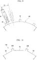
Fig. 6 is a cross-sectional view taken along line VI-VI ofFig. 5 . -
Fig. 7 is a view taken in the direction of arrow VII ofFig. 5 . -
Fig. 8 is a cross-sectional view that is for describing a method of manufacturing the outlet outer ring in the embodiment of the present invention and corresponds toFig. 6 . -
Fig. 9 is a cross-sectional view for describing a method of manufacturing an outlet outer ring in a comparative example. -
Fig. 10 is a cross-sectional view that illustrates the outlet outer ring of a modified example and corresponds toFig. 6 . - Hereinafter, an embodiment of the present invention will be described in detail with reference to the drawings.
- As illustrated in
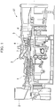
Fig. 1 , a gas turbine GT of the present embodiment is equipped with acompressor 1 that produces compressed air, acombustor 3 that burns fuel in the compressed air to produce a combustion gas, and a turbine 5 that is rotatably driven by the combustion gas. The turbine 5 has aturbine casing 6 in which acasing 7 is formed, and a turbine rotor 8 that is rotatably installed in thecasing 7. - The
compressor 1 takes in open air from its air intake 2 and compresses the open air, thereby producing the compressed air. Thecombustor 3 mixes fuel with the compressed air from thecompressor 1 and burns the fuel. A high-temperature high-pressure combustion gas produced by the combustion of the fuel rotatably drives the turbine rotor 8. - As illustrated in
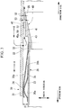
Fig. 2 , thecombustor 3 has afuel supplier 10 that injects the compressed air A from the compressor 1 (seeFig. 1 ) and the fuel, a combustor basket (first tube) 20 that supplies the compressed air A and the fuel from thefuel supplier 10, a transition piece (second tube) 30 that produces a combustion gas G from the compressed air A and the fuel supplied from thecombustor basket 20 and sends the produced combustion gas G to the turbine 5. Both thecombustor basket 20 and thetransition piece 30 of thecombustor 3 are disposed inside thecasing 7 of the turbine 5. - The
fuel supplier 10 is equipped with apilot burner 11 that supplies the compressed air A from thecompressor 1 and a pilot fuel, and a plurality ofnozzles 12 that premixes the compressed air A from thecompressor 1 and a main fuel into a premixed gas. - The
combustor basket 20 has a combustor basketmain body 39 that has a cylindrical shape and is disposed at a side of thecombustor basket 20 in a first direction, and an outletouter ring 40 that has an annular shape and is disposed at a side of thecombustor basket 20 in a second direction opposite to the first direction. Thefuel supplier 10 is installed at an end of thecombustor basket 20 in the first direction, and anopening 25 is formed in an end of thecombustor basket 20 in the second direction. The outletouter ring 40 forms a distal end of thecombustor basket 20. - In the following description, an end of the combustor basket
main body 39 in the first direction is defined as aproximal end 21, and an end of the combustor basketmain body 39 in the second direction is defined as adistal end 22. A side of theproximal end 21 that is the end in the first direction is defined as an upstream side, and a side of thedistal end 22 that is the end in the second direction is defined as a downstream side. A direction along an axis O of thecombustor basket 20 will be described as an axial direction, a direction along a circumference centered at the axis O will be described as a circumferential direction, and a direction along a radius of the circumference will be described as a radial direction. - The outlet
outer ring 40 is attached to thedistal end 22 of the combustor basketmain body 39. The outletouter ring 40 has a shape that causes the combustor basketmain body 39 to extend and increase in diameter toward the downstream side. - The
transition piece 30 has a tubular shape, and anopening 35 is formed in an end thereof in the first direction. An inner diameter of theopening 35 is greater than an outer diameter of thedistal end 22 of thecombustor basket 20 and an outer diameter of the outletouter ring 40. In the following description, an upstream end of thetransition piece 30 is defined as aproximal end 31. Thedistal end 22 of the combustor basketmain body 39 and the outletouter ring 40 are inserted into theproximal end 31 of thetransition piece 30. A downstream end of thetransition piece 30 is connected to a combustion passage of the turbine 5 (seeFig. 1 ). - The
fuel supplier 10 is fixed to theturbine casing 6. Theproximal end 21 of thecombustor basket 20 is supported on thefuel supplier 10 that is fixed to theturbine casing 6. Thedistal end 22 of the combustor basketmain body 39 is supported together with theproximal end 31 of thetransition piece 30 by a support member (not shown) installed on theturbine casing 6. - The
pilot burner 11 of thefuel supplier 10 and the plurality ofnozzles 12 are disposed inside thecombustor basket 20. Eachcombustor 3 is coupled with neighboringcombustors 3 via couplers (not shown). Flames of thecombustor 3 are propagated to the neighboringcombustors 3 via the couplers. - As illustrated in
Fig. 3 , at a connecting portion (fitting region) between thecombustor basket 20 and thetransition piece 30, there is a gap S1 between an outercircumferential surface 20b of the combustor basketmain body 39 and an innercircumferential surface 30a of thetransition piece 30. The gap S1 allows expansion and displacement due to heat of thecombustor basket 20 and thetransition piece 30. To seal the gap S1, aleaf spring 23 and aseal plate 24 supported by theleaf spring 23 are attached to the outercircumferential surface 20b adjacent to thedistal end 22 of the combustor basketmain body 39. - The
seal plate 24 is a cylindrical thin plate for sealing the connecting portion between thecombustor basket 20 and thetransition piece 30. Theseal plate 24 is formed with a plurality of slits (not shown) at intervals in the circumferential direction. An outer circumferential surface of the upstream side of theseal plate 24 is in contact with the innercircumferential surface 30a of thetransition piece 30, and an inner circumferential surface of the downstream side of theseal plate 24 is joined to the outercircumferential surface 20b of the combustor basketmain body 39. - The
leaf spring 23 is an elastic member that biases the upstream side of theseal plate 24 from a radially inner circumferential side toward the innercircumferential surface 30a of thetransition piece 30. Theleaf spring 23 has a cylindrical shape similarly to theseal plate 24. - The outlet
outer ring 40 connected to thedistal end 22 of the combustor basketmain body 39 has amain body 41 of a tubular shape and a plurality ofprotrusions 42 that are provided in an outer circumferential surface of themain body 41 in the circumferential direction and protrude to a radially outer side. Anextension surface 43 that has a tapered shape and is gradually increased in diameter toward the downstream side is formed at an inner circumferential side of themain body 41. The compressed air A and the fuel are smoothly supplied from thecombustor basket 20 to thetransition piece 30 by theextension surface 43. - As illustrated in
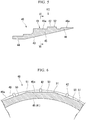
Figs. 4 and5 , themain body 41 of the outletouter ring 40 has afitting part 44 fitted into thedistal end 22 of the combustor basketmain body 39, apolygonal ring part 45, and arestrictor part 46 in this order from the upstream side. At least one cutout portion 47 (two cutout portions in the present embodiment) is formed in the outletouter ring 40. - The
cutout portions 47 are provided at a side of therestrictor part 46 in the axial direction. Thecutout portions 47 serve as paths of the flames propagated via coupling pipes. In the following description, a shape of themain body 41 will be described on the assumption that there are nocutout portions 47. The outletouter ring 40 is formed with thecutout portions 47 having different shapes corresponding to a position or shape of thecombustor 3 to be mounted. In addition, thecutout portions 47 are also used as parts connected to ignition plugs or for flame detection in addition to being used to propagate the flames. - The
fitting part 44 is shaped to be fitted with the innercircumferential surface 20a of thedistal end 22 of the combustor basketmain body 39 without a gap. That is, thefitting part 44 of the outletouter ring 40 has a smaller outer diameter than an inner diameter of thedistal end 22 of the combustor basketmain body 39. - An outer
circumferential surface 46a of therestrictor part 46 is formed in a cylindrical shape. A gap S2 is provided between the outercircumferential surface 46a of therestrictor part 46 and the innercircumferential surface 30a of the transition piece 30 (seeFig. 3 ). In other words, an outer diameter of therestrictor part 46 is set such that the gap S2 is formed between the outercircumferential surface 46a of therestrictor part 46 and the innercircumferential surface 30a of thetransition piece 30 when the outletouter ring 40 is attached to thedistal end 22 of the combustor basketmain body 39. - As illustrated in
Fig. 6 , thepolygonal ring part 45 has a polygonal cross-sectional shape when viewed in the axial direction. That is, an outercircumferential surface 45a of thepolygonal ring part 45 is not formed in an arc shape but has a plurality of outercircumferential planes 50 and a plurality ofridgelines 51 formed between one outercircumferential plane 50 and another outercircumferential plane 50. - The outer
circumferential surface 45a of thepolygonal ring part 45 of the present embodiment is formed in a 32-gonal cross-sectional shape having 32 planes and 32 ridgelines when viewed in the axial direction. The shape of the outercircumferential surface 45a of thepolygonal ring part 45 is not limited to the present embodiment but various polygonal shapes may be employed. The polygonal shape to be used may be adequately set depending on, for instance, a diameter of thecombustor basket 20. For example, in the case of a combustor basket having a smaller diameter than thecombustor basket 20 of the present embodiment, the shape may be set to a polygonal shape having fewer planes or ridgelines than that of the present embodiment, for instance, a 20-gonal shape. - The outer
circumferential planes 50 are formed at a radially inner side relative to the outercircumferential surface 46a of therestrictor part 46. In other words, a distance of each outercircumferential plane 50 from the central axis O is adapted to be shorter than a radius of the outercircumferential surface 46a of therestrictor part 46. Thereby, as illustrated inFig. 3 , a gap S3 between the outercircumferential plane 50 and the innercircumferential surface 30a of thetransition piece 30 is adapted to be greater than the gap S2. - As illustrated in
Fig. 5 , theprotrusions 42 have projected end faces 52 approximately parallel to the outercircumferential surface 45a. The projected end faces 52 are formed at a radially outer side relative to the outercircumferential surface 46a of therestrictor part 46. As illustrated inFig. 3 , the projected end faces 52 are formed such that heights thereof from the outercircumferential planes 50 are approximately equal to that of the gap S3. - As illustrated in
Fig. 7 , theprotrusions 42 are formed in approximately the centers of the outercircumferential planes 50 in the circumferential direction so as to extend in the axial direction. A cross-sectional shape of eachprotrusion 42 when viewed in the radial direction is a spindle shape extending in the axial direction. In other words, in theprotrusions 42, a cross section perpendicular to the radial direction has an elliptical shape that extends in a direction in which the compressed air A flows, and has a shape that disturbs the flow of the compressed air A flowing in from the upstream side as little as possible. - As illustrated in
Fig. 3 , a plurality of (e.g., eight) air supply holes 32 are formed adjacent to theproximal end 31 of thetransition piece 30 in the circumferential direction. Axial positions of the air supply holes 32 are downstream from theseal plate 24 and upstream from theprotrusions 42 when thetransition piece 30 and thecombustor basket 20 are combined. That is, the air supply holes 32 are formed at such positions that the compressed air A flowing in from the outer circumferential side of thetransition piece 30 flows in at a position which is downstream from theseal plate 24 at the gap S1 between thetransition piece 30 and thecombustor basket 20 and which is upstream from theprotrusions 42. - Next, a method of manufacturing the outlet
outer ring 40 of the present embodiment will be described. - The outlet
outer ring 40 of the present embodiment is manufactured by making an outline thereof using a machine tool such as a lathe, and then machining details using a machine tool such as a milling machine. Particularly, thepolygonal ring part 45 of the outletouter ring 40 is machined by an end mill of the milling machine because theprotrusions 42 protruding in the radial direction are integrally formed in thepolygonal ring part 45. - To be specific, as illustrated in
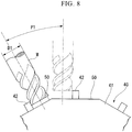
Fig. 8 , the outercircumferential planes 50 are machined using an end mill M such that theprotrusions 42 remain. In the present embodiment, since the number of outercircumferential planes 50 is 32, a relative angle between the end mill M and the workpiece is changed 32 times including first installation in order to machine the outer circumferential planes 50. That is, the outercircumferential planes 50 on which theprotrusions 42 are formed are machined by performing an angle change of apitch P1 32 times. - Next, an operation of the gas turbine GT of the present embodiment will be described. In the gas turbine GT, the compressed air A compressed by the
compressor 1 passes through a channel 14 (seeFig. 2 ) surrounded by the outer circumferential surface 30b of thetransition piece 30, the outercircumferential surface 20b of thecombustor basket 20, and an inner circumferential surface of theturbine casing 6, is reversed at areverse portion 15, and flows into thecombustor basket 20. - Next, the fuel supplied from the
pilot burner 11 and the plurality ofnozzles 12 of thefuel supplier 10 and the compressed air A are supplied from thecombustor basket 20 to thetransition piece 30. The fuel and the compressed air A supplied from thecombustor basket 20 form flames in thetransition piece 30. To be specific, diffusion flames are formed by the pilot fuel supplied from thepilot burner 11 and the compressed air A. Subsequently, a premixed gas produced by the plurality ofnozzles 12 premixing the main fuel and the compressed air A is ignited by the diffusion flames. Thereby, premixed flames are formed. - The combustion gas G produced by combustion of the pilot fuel and the main fuel is delivered from the
transition piece 30 into a turbine-side gas channel (not shown). The combustion gas G flowing into the turbine-side gas channel rotatably drives the turbine rotor 8 as described above. - As illustrated in
Fig. 3 , the compressed air A is taken into the space between thetransition piece 30 and thecombustor basket 20 via the air supply holes 32. Thus, the introduced compressed air A is ejected from the gap S2 between thetransition piece 30 and therestrictor part 46 of the outletouter ring 40 along the innercircumferential surface 30a of thetransition piece 30. - The compressed air A ejected to the
transition piece 30 forms a thin film on the innercircumferential surface 30a of thetransition piece 30. That is, the film of the compressed air A film-cools the innercircumferential surface 30a of thetransition piece 30, and protects the innercircumferential surface 30a of thetransition piece 30 from the fuel and the compressed air A supplied from theopening 25 of thecombustor basket 20 and the heat of the combustion gas G produced by the fuel and the compressed air A. - The compressed air A introduced into the
transition piece 30 from the gap S1 may be used as air for combustion. - According to the above embodiment, the compressed air A ejected from the gap S2 film-cools the
transition piece 30, and thereby burning of thetransition piece 30 can be suppressed. - The
protrusions 42 are formed on the outletouter ring 40. Thereby, the gap S3 through which the compressed air A for film-cooling thetransition piece 30 is supplied can be stably secured. - In addition, the
protrusions 42 are integrally formed on the outletouter ring 40. Thereby, the number of components for constituting thecombustor basket 20 of thecombustor 3 can be reduced. - The cross-sectional shape of each
protrusion 42 when viewed in the radial direction is the spindle shape along the axial direction. Thereby, disturbance of the compressed air A at the positions at which theprotrusions 42 are disposed is effectively suppressed. Thereby, uniformity of the compressed air A ejected from the gap S2 can be improved. - In addition, the
polygonal ring part 45 of the outletouter ring 40 is formed in the polygonal shape. Thereby, when the outercircumferential planes 50 of thepolygonal ring part 45 are formed, the number of times the relative angle between the working tool and the workpiece is changed is reduced. Thereby, working man-hours can be reduced. -
Fig. 9 is a cross-sectional view for describing a method of manufacturing an outletouter ring 140 of a comparative example. As illustrated inFig. 9 , in the outletouter ring 140 of the comparative example, a part corresponding to thepolygonal ring part 45 of the present embodiment is formed in a cylindrical shape when viewed in the axial direction. In the case of the outletouter ring 140 of the comparative example, a machining pitch P2 of the end mill M needs to be smaller than the pitch P1 illustrated inFig. 8 in order to machine the part corresponding to thepolygonal ring part 45. When the angle change is required, for instance, 360 times in order to approximate this part to the cylindrical shape, the pitch P2 becomes about 1 degree. - The
polygonal ring part 45 of the outletouter ring 40 of the present embodiment is formed in the polygonal shape. For example, thepolygonal ring part 45 of the present embodiment has the 32-gonal shape, and thus, as illustrated inFig. 8 , the pitch P1 becomes about 11 degrees. - The
polygonal ring part 45 has the polygonal shape. Thereby, the end mill M can be made larger in diameter. That is, when the machining pitch is small, the end mill M having a size corresponding to such a pitch is required. However, as the machining pitch is increased and a plane to be machined is increased, an increase in the diameter of the end mill M is allowed. That is, the diameter D1 of the end mill M that machines the outletouter ring 40 of the present embodiment can be greater than the diameter D2 of the end mill M that machines the outletouter ring 140 of the comparative example. - The outer
circumferential surface 46a of therestrictor part 46 is formed in the cylindrical shape, and the gap S2 between the outercircumferential surface 46a of therestrictor part 46 and the innercircumferential surface 30a of thetransition piece 30 is uniform. Thus, the compressed air A ejected from the gap S2 can be made uniform in the circumferential direction. - In addition, the
protrusions 42 are formed in the centers of the outercircumferential planes 50 of thepolygonal ring part 45 in the circumferential direction. Thereby, theprotrusions 42 are formed using the end mill M for forming the outer circumferential planes 50. As a result, it is possible to form the high-precision protrusions 42 in which a radial thickness is uniform and a circumferential surface is wide in the radial direction. - For example, as long as the
protrusions 42 of the outletouter ring 40 are integrally formed with themain body 41, theprotrusions 42 need not be formed in the centers of the outercircumferential planes 50 in the circumferential direction. As illustrated inFig. 10 ,protrusions 42B may each be formed on a ridgeline between one outercircumferential plane 50 and another outercircumferential plane 50. - The introduction of the compressed air A used for the film-cooling is not limited to the method of introduction through the air supply holes 32. Another introducing method may be used. For example, the compressed air A may be introduced from the slits formed in the
seal plate 24. - The shapes of the
protrusions 42 are not limited to the spindle shape when viewed in the radial direction. A shape that has no influence on the flow of the compressed air A may be appropriately employed. For example, the shape may be a circular shape when viewed in the radial direction. - In addition, the number of
protrusions 42 is not limited to one in each outercircumferential plane 50. A plurality ofprotrusions 42 may be formed in each outercircumferential plane 50. - According to this combustor, the main body and the protrusions are integrally formed at the ring part. Thereby, the number of components can be reduced, and the manufacturing costs of the combustor can be reduced. Also, when the outer circumferential surface of the main body being a workpiece is formed, the number of times the relative angle between the working tool and the workpiece is changed is reduced, and thus the machining man-hours can be reduced.
-
- 1
- compressor
- 2
- air intake
- 3
- combustor
- 5
- turbine
- 6
- turbine casing
- 7
- casing
- 8
- turbine rotor
- 10
- fuel supplier
- 11
- pilot burner
- 12
- nozzle
- 20
- combustor basket (first tube)
- 20a
- inner circumferential surface
- 20b
- outer circumferential surface
- 21
- proximal end
- 22
- distal end
- 23
- leaf spring
- 24
- seal plate
- 25
- opening
- 30
- transition piece (second tube)
- 30a
- inner circumferential surface
- 30b
- outer circumferential surface
- 31
- proximal end
- 32
- air supply hole
- 35
- opening
- 39
- combustor basket main body (first tube main body)
- 40
- outlet outer ring (ring part)
- 41
- main body
- 42
- protrusion
- 43
- extension surface
- 44
- fitting part
- 45
- polygonal ring part
- 45a
- outer circumferential surface
- 46
- restrictor part
- 46a
- outer circumferential surface
- 47
- cutout portion
- 50
- outer circumferential plane
- 51
- ridgeline
- 52
- projected end face
- A
- compressed air
- G
- combustion gas
- GT
- gas turbine
- S1
- gap
- S2
- gap
- S3
- gap
Claims (5)
- A combustor (3) comprising:a first tube (20) which is configured such that fuel and air (A) can be supplied from an opening (25) formed in a distal end (22) thereof; anda second tube (30) to which the fuel and air (A) are supplied from the opening (25) of the first tube (20), wherein the second tube (30) is configured such that the distal end (22) of the first tube (20) is inserted into an inner circumferential side of a proximal end (31) thereof,wherein the first tube (20) includes a first tube main body (39) and a ring part (40) forming the distal end (22) of the first tube (20), andthe ring part (40) has a main body (41) of a tubular shape and a plurality of protrusions (42) on an outer circumferential surface (45a) of the main body (41) and protruding radially outward,characterized in thatthe plurality of protrusions (42) are integrally formed with the main body (41) on the outer circumferential surface (45a) of the main body (41), andwhen viewed in an axial direction along an axis of the first tube (20), the outer circumferential surface (45a) of the main body (41) being machined to a polygonal cross-sectional shape within a range within which the protrusions (42) are formed.
- The combustor (3) according to claim 1, wherein the main body (41) includes a polygonal ring part (45) on which the protrusions (42) are formed, and a restrictor part (46) which is provided at a distal end side relative to the polygonal ring part (45) and an outer circumferential surface (46a) of which is formed in a cylindrical shape at a radially outer circumferential side relative to an outer circumferential surface of the polygonal ring part (46).
- The combustor (3) according to claim 2, wherein the protrusions (42) are formed in centers of outer circumferential planes (50) of the polygonal ring part (45) in a circumferential direction.
- The combustor (3) according to any one of claims 1 to 3, wherein, when viewed in a radial direction along a radius of the first tube (20), the protrusions (42) have a cross-section perpendicular to the radial direction that has an elliptical shape that extends in the axial direction.
- A gas turbine (GT) comprising:the combustor (3) according to any one of claims 1 to 4; anda turbine (5) arranged to be driven by a combustion gas delivered from the second tube (30) of the combustor (3).
Applications Claiming Priority (2)
| Application Number | Priority Date | Filing Date | Title |
|---|---|---|---|
| JP2013053149A JP6082287B2 (en) | 2013-03-15 | 2013-03-15 | Combustor, gas turbine, and first cylinder of combustor |
| PCT/JP2014/053771 WO2014141825A1 (en) | 2013-03-15 | 2014-02-18 | Combustor and gas turbine |
Publications (3)
| Publication Number | Publication Date |
|---|---|
| EP2949904A1 EP2949904A1 (en) | 2015-12-02 |
| EP2949904A4 EP2949904A4 (en) | 2016-04-20 |
| EP2949904B1 true EP2949904B1 (en) | 2017-08-02 |
Family
ID=51536500
Family Applications (1)
| Application Number | Title | Priority Date | Filing Date |
|---|---|---|---|
| EP14762567.7A Active EP2949904B1 (en) | 2013-03-15 | 2014-02-18 | Combustor and gas turbine |
Country Status (6)
| Country | Link |
|---|---|
| US (1) | US9939158B2 (en) |
| EP (1) | EP2949904B1 (en) |
| JP (1) | JP6082287B2 (en) |
| KR (1) | KR101716602B1 (en) |
| CN (1) | CN105008696B (en) |
| WO (1) | WO2014141825A1 (en) |
Families Citing this family (7)
| Publication number | Priority date | Publication date | Assignee | Title |
|---|---|---|---|---|
| JP6485942B2 (en) * | 2014-09-25 | 2019-03-20 | 三菱日立パワーシステムズ株式会社 | Combustor, gas turbine |
| JP6521283B2 (en) * | 2014-09-25 | 2019-05-29 | 三菱日立パワーシステムズ株式会社 | Combustor, gas turbine |
| US20170142395A1 (en) * | 2015-11-13 | 2017-05-18 | Craig Peterson | 3d system including pop out adjustment |
| KR102071168B1 (en) * | 2016-05-23 | 2020-01-29 | 미츠비시 히타치 파워 시스템즈 가부시키가이샤 | Combustor, gas turbine |
| JP6590771B2 (en) | 2016-08-09 | 2019-10-16 | 三菱日立パワーシステムズ株式会社 | Gas turbine combustor |
| JP6779098B2 (en) * | 2016-10-24 | 2020-11-04 | 三菱パワー株式会社 | Gas turbine combustor |
| WO2021166092A1 (en) * | 2020-02-19 | 2021-08-26 | 三菱重工エンジン&ターボチャージャ株式会社 | Combustor and gas turbine |
Family Cites Families (13)
| Publication number | Priority date | Publication date | Assignee | Title |
|---|---|---|---|---|
| US3359724A (en) * | 1965-08-03 | 1967-12-26 | Bristol Siddeley Engines Ltd | Cooling means in combustors for gas turbine engines |
| FR2155835B1 (en) * | 1971-10-08 | 1974-05-31 | Snecma | |
| US3956886A (en) * | 1973-12-07 | 1976-05-18 | Joseph Lucas (Industries) Limited | Flame tubes for gas turbine engines |
| JPS5857657B2 (en) * | 1980-02-01 | 1983-12-21 | 工業技術院長 | Inner cylinder of gas turbine combustor |
| JPH10238777A (en) * | 1997-02-28 | 1998-09-08 | Hitachi Ltd | Gas turbine combustor |
| JP3924136B2 (en) * | 2001-06-27 | 2007-06-06 | 三菱重工業株式会社 | Gas turbine combustor |
| EP1284390A1 (en) * | 2001-06-27 | 2003-02-19 | Siemens Aktiengesellschaft | Thermal shield for a component carrying hot gases, especially for structural components of gas turbines |
| JP4709433B2 (en) * | 2001-06-29 | 2011-06-22 | 三菱重工業株式会社 | Gas turbine combustor |
| JP2005171894A (en) | 2003-12-11 | 2005-06-30 | Mitsubishi Heavy Ind Ltd | Combustor wall surface cooling structure |
| US20100186415A1 (en) * | 2009-01-23 | 2010-07-29 | General Electric Company | Turbulated aft-end liner assembly and related cooling method |
| US20120180500A1 (en) * | 2011-01-13 | 2012-07-19 | General Electric Company | System for damping vibration in a gas turbine engine |
| JP5669928B2 (en) * | 2011-03-30 | 2015-02-18 | 三菱重工業株式会社 | Combustor and gas turbine provided with the same |
| JP2013181672A (en) * | 2012-02-29 | 2013-09-12 | Mitsubishi Heavy Ind Ltd | Combustor, and gas turbine with the same |
-
2013
- 2013-03-15 JP JP2013053149A patent/JP6082287B2/en active Active
-
2014
- 2014-02-18 EP EP14762567.7A patent/EP2949904B1/en active Active
- 2014-02-18 KR KR1020157023033A patent/KR101716602B1/en active IP Right Grant
- 2014-02-18 US US14/770,638 patent/US9939158B2/en active Active
- 2014-02-18 WO PCT/JP2014/053771 patent/WO2014141825A1/en active Application Filing
- 2014-02-18 CN CN201480010620.1A patent/CN105008696B/en active Active
Non-Patent Citations (1)
| Title |
|---|
| None * |
Also Published As
| Publication number | Publication date |
|---|---|
| KR20150110757A (en) | 2015-10-02 |
| US20160003481A1 (en) | 2016-01-07 |
| EP2949904A4 (en) | 2016-04-20 |
| EP2949904A1 (en) | 2015-12-02 |
| JP2014177909A (en) | 2014-09-25 |
| WO2014141825A1 (en) | 2014-09-18 |
| CN105008696B (en) | 2017-10-03 |
| CN105008696A (en) | 2015-10-28 |
| US9939158B2 (en) | 2018-04-10 |
| KR101716602B1 (en) | 2017-03-14 |
| JP6082287B2 (en) | 2017-02-15 |
Similar Documents
| Publication | Publication Date | Title |
|---|---|---|
| EP2949904B1 (en) | Combustor and gas turbine | |
| US8919673B2 (en) | Apparatus and method for a fuel nozzle | |
| EP3282191B1 (en) | Pilot premix nozzle and fuel nozzle assembly | |
| EP1434007B1 (en) | Gas turbine can annular combustor | |
| EP3171088B1 (en) | Bundled tube fuel nozzle assembly with liquid fuel capability | |
| JP4818895B2 (en) | Fuel mixture injection device, combustion chamber and turbine engine equipped with such device | |
| EP2864707B1 (en) | Turbine engine combustor wall with non-uniform distribution of effusion apertures | |
| EP2728263B1 (en) | A combustor | |
| US9175857B2 (en) | Combustor cap assembly | |
| EP3147570B1 (en) | Premix fuel nozzle assembly | |
| US20190178495A1 (en) | New w501d5/d5a df42 combustion system | |
| EP3575686B1 (en) | Double wall combustors with strain isolated inserts | |
| EP3211318A2 (en) | Gas-only cartridge for a premix fuel nozzle | |
| US20170363294A1 (en) | Pilot premix nozzle and fuel nozzle assembly | |
| JP2009030964A (en) | Fuel nozzle for gas turbine engine and method for manufacturing the same | |
| JP5389250B2 (en) | Burner assembly | |
| US9423136B2 (en) | Bundled tube fuel injector aft plate retention | |
| EP3309457B1 (en) | Combustion dynamics mitigation system | |
| JP5718796B2 (en) | Gas turbine combustor with sealing member | |
| JP2011169579A (en) | Burner device | |
| US20170350321A1 (en) | Bundled Tube Fuel Nozzle Assembly with Tube Extensions |
Legal Events
| Date | Code | Title | Description |
|---|---|---|---|
| PUAI | Public reference made under article 153(3) epc to a published international application that has entered the european phase |
Free format text: ORIGINAL CODE: 0009012 |
|
| 17P | Request for examination filed |
Effective date: 20150826 |
|
| AK | Designated contracting states |
Kind code of ref document: A1 Designated state(s): AL AT BE BG CH CY CZ DE DK EE ES FI FR GB GR HR HU IE IS IT LI LT LU LV MC MK MT NL NO PL PT RO RS SE SI SK SM TR |
|
| AX | Request for extension of the european patent |
Extension state: BA ME |
|
| A4 | Supplementary search report drawn up and despatched |
Effective date: 20160322 |
|
| RIC1 | Information provided on ipc code assigned before grant |
Ipc: F01D 9/02 20060101ALI20160316BHEP Ipc: F23R 3/54 20060101ALI20160316BHEP Ipc: F23R 3/42 20060101ALI20160316BHEP Ipc: F23R 3/46 20060101ALI20160316BHEP Ipc: F02C 3/04 20060101ALI20160316BHEP Ipc: F02C 7/18 20060101AFI20160316BHEP |
|
| DAX | Request for extension of the european patent (deleted) | ||
| GRAP | Despatch of communication of intention to grant a patent |
Free format text: ORIGINAL CODE: EPIDOSNIGR1 |
|
| INTG | Intention to grant announced |
Effective date: 20170313 |
|
| GRAS | Grant fee paid |
Free format text: ORIGINAL CODE: EPIDOSNIGR3 |
|
| GRAA | (expected) grant |
Free format text: ORIGINAL CODE: 0009210 |
|
| AK | Designated contracting states |
Kind code of ref document: B1 Designated state(s): AL AT BE BG CH CY CZ DE DK EE ES FI FR GB GR HR HU IE IS IT LI LT LU LV MC MK MT NL NO PL PT RO RS SE SI SK SM TR |
|
| RAP1 | Party data changed (applicant data changed or rights of an application transferred) |
Owner name: MITSUBISHI HITACHI POWER SYSTEMS, LTD. |
|
| REG | Reference to a national code |
Ref country code: CH Ref legal event code: EP Ref country code: AT Ref legal event code: REF Ref document number: 914757 Country of ref document: AT Kind code of ref document: T Effective date: 20170815 |
|
| REG | Reference to a national code |
Ref country code: IE Ref legal event code: FG4D |
|
| REG | Reference to a national code |
Ref country code: DE Ref legal event code: R096 Ref document number: 602014012639 Country of ref document: DE |
|
| REG | Reference to a national code |
Ref country code: NL Ref legal event code: MP Effective date: 20170802 |
|
| REG | Reference to a national code |
Ref country code: AT Ref legal event code: MK05 Ref document number: 914757 Country of ref document: AT Kind code of ref document: T Effective date: 20170802 |
|
| REG | Reference to a national code |
Ref country code: LT Ref legal event code: MG4D |
|
| PG25 | Lapsed in a contracting state [announced via postgrant information from national office to epo] |
Ref country code: HR Free format text: LAPSE BECAUSE OF FAILURE TO SUBMIT A TRANSLATION OF THE DESCRIPTION OR TO PAY THE FEE WITHIN THE PRESCRIBED TIME-LIMIT Effective date: 20170802 Ref country code: SE Free format text: LAPSE BECAUSE OF FAILURE TO SUBMIT A TRANSLATION OF THE DESCRIPTION OR TO PAY THE FEE WITHIN THE PRESCRIBED TIME-LIMIT Effective date: 20170802 Ref country code: NO Free format text: LAPSE BECAUSE OF FAILURE TO SUBMIT A TRANSLATION OF THE DESCRIPTION OR TO PAY THE FEE WITHIN THE PRESCRIBED TIME-LIMIT Effective date: 20171102 Ref country code: FI Free format text: LAPSE BECAUSE OF FAILURE TO SUBMIT A TRANSLATION OF THE DESCRIPTION OR TO PAY THE FEE WITHIN THE PRESCRIBED TIME-LIMIT Effective date: 20170802 Ref country code: AT Free format text: LAPSE BECAUSE OF FAILURE TO SUBMIT A TRANSLATION OF THE DESCRIPTION OR TO PAY THE FEE WITHIN THE PRESCRIBED TIME-LIMIT Effective date: 20170802 Ref country code: LT Free format text: LAPSE BECAUSE OF FAILURE TO SUBMIT A TRANSLATION OF THE DESCRIPTION OR TO PAY THE FEE WITHIN THE PRESCRIBED TIME-LIMIT Effective date: 20170802 Ref country code: NL Free format text: LAPSE BECAUSE OF FAILURE TO SUBMIT A TRANSLATION OF THE DESCRIPTION OR TO PAY THE FEE WITHIN THE PRESCRIBED TIME-LIMIT Effective date: 20170802 |
|
| PG25 | Lapsed in a contracting state [announced via postgrant information from national office to epo] |
Ref country code: IS Free format text: LAPSE BECAUSE OF FAILURE TO SUBMIT A TRANSLATION OF THE DESCRIPTION OR TO PAY THE FEE WITHIN THE PRESCRIBED TIME-LIMIT Effective date: 20171202 Ref country code: PL Free format text: LAPSE BECAUSE OF FAILURE TO SUBMIT A TRANSLATION OF THE DESCRIPTION OR TO PAY THE FEE WITHIN THE PRESCRIBED TIME-LIMIT Effective date: 20170802 Ref country code: BG Free format text: LAPSE BECAUSE OF FAILURE TO SUBMIT A TRANSLATION OF THE DESCRIPTION OR TO PAY THE FEE WITHIN THE PRESCRIBED TIME-LIMIT Effective date: 20171102 Ref country code: GR Free format text: LAPSE BECAUSE OF FAILURE TO SUBMIT A TRANSLATION OF THE DESCRIPTION OR TO PAY THE FEE WITHIN THE PRESCRIBED TIME-LIMIT Effective date: 20171103 Ref country code: LV Free format text: LAPSE BECAUSE OF FAILURE TO SUBMIT A TRANSLATION OF THE DESCRIPTION OR TO PAY THE FEE WITHIN THE PRESCRIBED TIME-LIMIT Effective date: 20170802 Ref country code: ES Free format text: LAPSE BECAUSE OF FAILURE TO SUBMIT A TRANSLATION OF THE DESCRIPTION OR TO PAY THE FEE WITHIN THE PRESCRIBED TIME-LIMIT Effective date: 20170802 Ref country code: RS Free format text: LAPSE BECAUSE OF FAILURE TO SUBMIT A TRANSLATION OF THE DESCRIPTION OR TO PAY THE FEE WITHIN THE PRESCRIBED TIME-LIMIT Effective date: 20170802 |
|
| PG25 | Lapsed in a contracting state [announced via postgrant information from national office to epo] |
Ref country code: CZ Free format text: LAPSE BECAUSE OF FAILURE TO SUBMIT A TRANSLATION OF THE DESCRIPTION OR TO PAY THE FEE WITHIN THE PRESCRIBED TIME-LIMIT Effective date: 20170802 Ref country code: RO Free format text: LAPSE BECAUSE OF FAILURE TO SUBMIT A TRANSLATION OF THE DESCRIPTION OR TO PAY THE FEE WITHIN THE PRESCRIBED TIME-LIMIT Effective date: 20170802 Ref country code: DK Free format text: LAPSE BECAUSE OF FAILURE TO SUBMIT A TRANSLATION OF THE DESCRIPTION OR TO PAY THE FEE WITHIN THE PRESCRIBED TIME-LIMIT Effective date: 20170802 |
|
| REG | Reference to a national code |
Ref country code: DE Ref legal event code: R097 Ref document number: 602014012639 Country of ref document: DE |
|
| PG25 | Lapsed in a contracting state [announced via postgrant information from national office to epo] |
Ref country code: EE Free format text: LAPSE BECAUSE OF FAILURE TO SUBMIT A TRANSLATION OF THE DESCRIPTION OR TO PAY THE FEE WITHIN THE PRESCRIBED TIME-LIMIT Effective date: 20170802 Ref country code: SK Free format text: LAPSE BECAUSE OF FAILURE TO SUBMIT A TRANSLATION OF THE DESCRIPTION OR TO PAY THE FEE WITHIN THE PRESCRIBED TIME-LIMIT Effective date: 20170802 Ref country code: SM Free format text: LAPSE BECAUSE OF FAILURE TO SUBMIT A TRANSLATION OF THE DESCRIPTION OR TO PAY THE FEE WITHIN THE PRESCRIBED TIME-LIMIT Effective date: 20170802 Ref country code: IT Free format text: LAPSE BECAUSE OF FAILURE TO SUBMIT A TRANSLATION OF THE DESCRIPTION OR TO PAY THE FEE WITHIN THE PRESCRIBED TIME-LIMIT Effective date: 20170802 |
|
| PLBE | No opposition filed within time limit |
Free format text: ORIGINAL CODE: 0009261 |
|
| STAA | Information on the status of an ep patent application or granted ep patent |
Free format text: STATUS: NO OPPOSITION FILED WITHIN TIME LIMIT |
|
| 26N | No opposition filed |
Effective date: 20180503 |
|
| PG25 | Lapsed in a contracting state [announced via postgrant information from national office to epo] |
Ref country code: SI Free format text: LAPSE BECAUSE OF FAILURE TO SUBMIT A TRANSLATION OF THE DESCRIPTION OR TO PAY THE FEE WITHIN THE PRESCRIBED TIME-LIMIT Effective date: 20170802 |
|
| REG | Reference to a national code |
Ref country code: CH Ref legal event code: PL |
|
| PG25 | Lapsed in a contracting state [announced via postgrant information from national office to epo] |
Ref country code: MC Free format text: LAPSE BECAUSE OF FAILURE TO SUBMIT A TRANSLATION OF THE DESCRIPTION OR TO PAY THE FEE WITHIN THE PRESCRIBED TIME-LIMIT Effective date: 20170802 |
|
| REG | Reference to a national code |
Ref country code: IE Ref legal event code: MM4A |
|
| REG | Reference to a national code |
Ref country code: BE Ref legal event code: MM Effective date: 20180228 |
|
| PG25 | Lapsed in a contracting state [announced via postgrant information from national office to epo] |
Ref country code: LI Free format text: LAPSE BECAUSE OF NON-PAYMENT OF DUE FEES Effective date: 20180228 Ref country code: CH Free format text: LAPSE BECAUSE OF NON-PAYMENT OF DUE FEES Effective date: 20180228 Ref country code: LU Free format text: LAPSE BECAUSE OF NON-PAYMENT OF DUE FEES Effective date: 20180218 |
|
| REG | Reference to a national code |
Ref country code: FR Ref legal event code: ST Effective date: 20181031 |
|
| PG25 | Lapsed in a contracting state [announced via postgrant information from national office to epo] |
Ref country code: IE Free format text: LAPSE BECAUSE OF NON-PAYMENT OF DUE FEES Effective date: 20180218 |
|
| PG25 | Lapsed in a contracting state [announced via postgrant information from national office to epo] |
Ref country code: FR Free format text: LAPSE BECAUSE OF NON-PAYMENT OF DUE FEES Effective date: 20180228 Ref country code: BE Free format text: LAPSE BECAUSE OF NON-PAYMENT OF DUE FEES Effective date: 20180228 |
|
| PG25 | Lapsed in a contracting state [announced via postgrant information from national office to epo] |
Ref country code: MT Free format text: LAPSE BECAUSE OF NON-PAYMENT OF DUE FEES Effective date: 20180218 |
|
| PG25 | Lapsed in a contracting state [announced via postgrant information from national office to epo] |
Ref country code: TR Free format text: LAPSE BECAUSE OF FAILURE TO SUBMIT A TRANSLATION OF THE DESCRIPTION OR TO PAY THE FEE WITHIN THE PRESCRIBED TIME-LIMIT Effective date: 20170802 |
|
| PG25 | Lapsed in a contracting state [announced via postgrant information from national office to epo] |
Ref country code: PT Free format text: LAPSE BECAUSE OF FAILURE TO SUBMIT A TRANSLATION OF THE DESCRIPTION OR TO PAY THE FEE WITHIN THE PRESCRIBED TIME-LIMIT Effective date: 20170802 |
|
| PG25 | Lapsed in a contracting state [announced via postgrant information from national office to epo] |
Ref country code: MK Free format text: LAPSE BECAUSE OF NON-PAYMENT OF DUE FEES Effective date: 20170802 Ref country code: CY Free format text: LAPSE BECAUSE OF FAILURE TO SUBMIT A TRANSLATION OF THE DESCRIPTION OR TO PAY THE FEE WITHIN THE PRESCRIBED TIME-LIMIT Effective date: 20170802 Ref country code: HU Free format text: LAPSE BECAUSE OF FAILURE TO SUBMIT A TRANSLATION OF THE DESCRIPTION OR TO PAY THE FEE WITHIN THE PRESCRIBED TIME-LIMIT; INVALID AB INITIO Effective date: 20140218 |
|
| PG25 | Lapsed in a contracting state [announced via postgrant information from national office to epo] |
Ref country code: AL Free format text: LAPSE BECAUSE OF FAILURE TO SUBMIT A TRANSLATION OF THE DESCRIPTION OR TO PAY THE FEE WITHIN THE PRESCRIBED TIME-LIMIT Effective date: 20170802 |
|
| REG | Reference to a national code |
Ref country code: DE Ref legal event code: R082 Ref document number: 602014012639 Country of ref document: DE Representative=s name: HENKEL & PARTNER MBB PATENTANWALTSKANZLEI, REC, DE Ref country code: DE Ref legal event code: R081 Ref document number: 602014012639 Country of ref document: DE Owner name: MITSUBISHI POWER, LTD., JP Free format text: FORMER OWNER: MITSUBISHI HITACHI POWER SYSTEMS, LTD., YOKOHAMA-SHI, KANAGAWA, JP |
|
| PGFP | Annual fee paid to national office [announced via postgrant information from national office to epo] |
Ref country code: DE Payment date: 20231228 Year of fee payment: 11 Ref country code: GB Payment date: 20240108 Year of fee payment: 11 |