EP3211318A2 - Gas-only cartridge for a premix fuel nozzle - Google Patents
Gas-only cartridge for a premix fuel nozzle Download PDFInfo
- Publication number
- EP3211318A2 EP3211318A2 EP17156619.3A EP17156619A EP3211318A2 EP 3211318 A2 EP3211318 A2 EP 3211318A2 EP 17156619 A EP17156619 A EP 17156619A EP 3211318 A2 EP3211318 A2 EP 3211318A2
- Authority
- EP
- European Patent Office
- Prior art keywords
- fuel
- gas
- cartridge
- tip
- fluid communication
- Prior art date
- Legal status (The legal status is an assumption and is not a legal conclusion. Google has not performed a legal analysis and makes no representation as to the accuracy of the status listed.)
- Pending
Links
- 239000000446 fuel Substances 0.000 title claims abstract description 228
- 239000012530 fluid Substances 0.000 claims abstract description 47
- 238000004891 communication Methods 0.000 claims abstract description 42
- 238000011144 upstream manufacturing Methods 0.000 claims description 17
- 239000007789 gas Substances 0.000 description 82
- 238000002485 combustion reaction Methods 0.000 description 21
- MWUXSHHQAYIFBG-UHFFFAOYSA-N Nitric oxide Chemical compound O=[N] MWUXSHHQAYIFBG-UHFFFAOYSA-N 0.000 description 12
- 238000010926 purge Methods 0.000 description 8
- 239000000567 combustion gas Substances 0.000 description 6
- 238000001816 cooling Methods 0.000 description 6
- 239000007788 liquid Substances 0.000 description 6
- 239000000203 mixture Substances 0.000 description 6
- 238000010586 diagram Methods 0.000 description 3
- 230000009977 dual effect Effects 0.000 description 3
- 239000002826 coolant Substances 0.000 description 2
- 230000005611 electricity Effects 0.000 description 2
- 238000005516 engineering process Methods 0.000 description 2
- 238000002347 injection Methods 0.000 description 2
- 239000007924 injection Substances 0.000 description 2
- VNWKTOKETHGBQD-UHFFFAOYSA-N methane Chemical compound C VNWKTOKETHGBQD-UHFFFAOYSA-N 0.000 description 2
- 238000012986 modification Methods 0.000 description 2
- 230000004048 modification Effects 0.000 description 2
- 230000003247 decreasing effect Effects 0.000 description 1
- 238000013461 design Methods 0.000 description 1
- 238000000034 method Methods 0.000 description 1
- 239000003345 natural gas Substances 0.000 description 1
- 230000037361 pathway Effects 0.000 description 1
- 238000011160 research Methods 0.000 description 1
- 238000012552 review Methods 0.000 description 1
Images


Classifications
-
- F—MECHANICAL ENGINEERING; LIGHTING; HEATING; WEAPONS; BLASTING
- F23—COMBUSTION APPARATUS; COMBUSTION PROCESSES
- F23R—GENERATING COMBUSTION PRODUCTS OF HIGH PRESSURE OR HIGH VELOCITY, e.g. GAS-TURBINE COMBUSTION CHAMBERS
- F23R3/00—Continuous combustion chambers using liquid or gaseous fuel
- F23R3/28—Continuous combustion chambers using liquid or gaseous fuel characterised by the fuel supply
-
- F—MECHANICAL ENGINEERING; LIGHTING; HEATING; WEAPONS; BLASTING
- F23—COMBUSTION APPARATUS; COMBUSTION PROCESSES
- F23D—BURNERS
- F23D14/00—Burners for combustion of a gas, e.g. of a gas stored under pressure as a liquid
- F23D14/02—Premix gas burners, i.e. in which gaseous fuel is mixed with combustion air upstream of the combustion zone
-
- F—MECHANICAL ENGINEERING; LIGHTING; HEATING; WEAPONS; BLASTING
- F23—COMBUSTION APPARATUS; COMBUSTION PROCESSES
- F23D—BURNERS
- F23D14/00—Burners for combustion of a gas, e.g. of a gas stored under pressure as a liquid
- F23D14/46—Details, e.g. noise reduction means
- F23D14/48—Nozzles
- F23D14/58—Nozzles characterised by the shape or arrangement of the outlet or outlets from the nozzle, e.g. of annular configuration
-
- F—MECHANICAL ENGINEERING; LIGHTING; HEATING; WEAPONS; BLASTING
- F23—COMBUSTION APPARATUS; COMBUSTION PROCESSES
- F23R—GENERATING COMBUSTION PRODUCTS OF HIGH PRESSURE OR HIGH VELOCITY, e.g. GAS-TURBINE COMBUSTION CHAMBERS
- F23R3/00—Continuous combustion chambers using liquid or gaseous fuel
- F23R3/02—Continuous combustion chambers using liquid or gaseous fuel characterised by the air-flow or gas-flow configuration
- F23R3/04—Air inlet arrangements
- F23R3/10—Air inlet arrangements for primary air
- F23R3/12—Air inlet arrangements for primary air inducing a vortex
- F23R3/14—Air inlet arrangements for primary air inducing a vortex by using swirl vanes
-
- F—MECHANICAL ENGINEERING; LIGHTING; HEATING; WEAPONS; BLASTING
- F23—COMBUSTION APPARATUS; COMBUSTION PROCESSES
- F23R—GENERATING COMBUSTION PRODUCTS OF HIGH PRESSURE OR HIGH VELOCITY, e.g. GAS-TURBINE COMBUSTION CHAMBERS
- F23R3/00—Continuous combustion chambers using liquid or gaseous fuel
- F23R3/28—Continuous combustion chambers using liquid or gaseous fuel characterised by the fuel supply
- F23R3/286—Continuous combustion chambers using liquid or gaseous fuel characterised by the fuel supply having fuel-air premixing devices
-
- F—MECHANICAL ENGINEERING; LIGHTING; HEATING; WEAPONS; BLASTING
- F23—COMBUSTION APPARATUS; COMBUSTION PROCESSES
- F23R—GENERATING COMBUSTION PRODUCTS OF HIGH PRESSURE OR HIGH VELOCITY, e.g. GAS-TURBINE COMBUSTION CHAMBERS
- F23R3/00—Continuous combustion chambers using liquid or gaseous fuel
- F23R3/28—Continuous combustion chambers using liquid or gaseous fuel characterised by the fuel supply
- F23R3/30—Continuous combustion chambers using liquid or gaseous fuel characterised by the fuel supply comprising fuel prevapourising devices
- F23R3/32—Continuous combustion chambers using liquid or gaseous fuel characterised by the fuel supply comprising fuel prevapourising devices being tubular
-
- F—MECHANICAL ENGINEERING; LIGHTING; HEATING; WEAPONS; BLASTING
- F23—COMBUSTION APPARATUS; COMBUSTION PROCESSES
- F23R—GENERATING COMBUSTION PRODUCTS OF HIGH PRESSURE OR HIGH VELOCITY, e.g. GAS-TURBINE COMBUSTION CHAMBERS
- F23R3/00—Continuous combustion chambers using liquid or gaseous fuel
- F23R3/28—Continuous combustion chambers using liquid or gaseous fuel characterised by the fuel supply
- F23R3/38—Continuous combustion chambers using liquid or gaseous fuel characterised by the fuel supply comprising rotary fuel injection means
-
- F—MECHANICAL ENGINEERING; LIGHTING; HEATING; WEAPONS; BLASTING
- F23—COMBUSTION APPARATUS; COMBUSTION PROCESSES
- F23R—GENERATING COMBUSTION PRODUCTS OF HIGH PRESSURE OR HIGH VELOCITY, e.g. GAS-TURBINE COMBUSTION CHAMBERS
- F23R3/00—Continuous combustion chambers using liquid or gaseous fuel
- F23R3/42—Continuous combustion chambers using liquid or gaseous fuel characterised by the arrangement or form of the flame tubes or combustion chambers
- F23R3/46—Combustion chambers comprising an annular arrangement of several essentially tubular flame tubes within a common annular casing or within individual casings
-
- F—MECHANICAL ENGINEERING; LIGHTING; HEATING; WEAPONS; BLASTING
- F23—COMBUSTION APPARATUS; COMBUSTION PROCESSES
- F23D—BURNERS
- F23D17/00—Burners for combustion conjointly or alternatively of gaseous or liquid or pulverulent fuel
- F23D17/002—Burners for combustion conjointly or alternatively of gaseous or liquid or pulverulent fuel gaseous or liquid fuel
-
- F—MECHANICAL ENGINEERING; LIGHTING; HEATING; WEAPONS; BLASTING
- F23—COMBUSTION APPARATUS; COMBUSTION PROCESSES
- F23D—BURNERS
- F23D2204/00—Burners adapted for simultaneous or alternative combustion having more than one fuel supply
- F23D2204/10—Burners adapted for simultaneous or alternative combustion having more than one fuel supply gaseous and liquid fuel
-
- F—MECHANICAL ENGINEERING; LIGHTING; HEATING; WEAPONS; BLASTING
- F23—COMBUSTION APPARATUS; COMBUSTION PROCESSES
- F23D—BURNERS
- F23D2900/00—Special features of, or arrangements for burners using fluid fuels or solid fuels suspended in a carrier gas
- F23D2900/00016—Preventing or reducing deposit build-up on burner parts, e.g. from carbon
-
- F—MECHANICAL ENGINEERING; LIGHTING; HEATING; WEAPONS; BLASTING
- F23—COMBUSTION APPARATUS; COMBUSTION PROCESSES
- F23D—BURNERS
- F23D2900/00—Special features of, or arrangements for burners using fluid fuels or solid fuels suspended in a carrier gas
- F23D2900/14—Special features of gas burners
- F23D2900/14021—Premixing burners with swirling or vortices creating means for fuel or air
-
- F—MECHANICAL ENGINEERING; LIGHTING; HEATING; WEAPONS; BLASTING
- F23—COMBUSTION APPARATUS; COMBUSTION PROCESSES
- F23D—BURNERS
- F23D2900/00—Special features of, or arrangements for burners using fluid fuels or solid fuels suspended in a carrier gas
- F23D2900/14—Special features of gas burners
- F23D2900/14701—Swirling means inside the mixing tube or chamber to improve premixing
-
- F—MECHANICAL ENGINEERING; LIGHTING; HEATING; WEAPONS; BLASTING
- F23—COMBUSTION APPARATUS; COMBUSTION PROCESSES
- F23R—GENERATING COMBUSTION PRODUCTS OF HIGH PRESSURE OR HIGH VELOCITY, e.g. GAS-TURBINE COMBUSTION CHAMBERS
- F23R3/00—Continuous combustion chambers using liquid or gaseous fuel
- F23R3/28—Continuous combustion chambers using liquid or gaseous fuel characterised by the fuel supply
- F23R3/36—Supply of different fuels
Landscapes
- Engineering & Computer Science (AREA)
- Chemical & Material Sciences (AREA)
- Combustion & Propulsion (AREA)
- Mechanical Engineering (AREA)
- General Engineering & Computer Science (AREA)
- Gas Burners (AREA)
- Feeding And Controlling Fuel (AREA)
Abstract
Description
- This invention was made with government support under Contract No. DE-FC26-05NT42643 awarded by the Department of Energy. The government has certain rights in the invention.
- The subject matter disclosed herein relates to a fuel nozzle for a combustion system. More particularly, the disclosure is directed to a gas-only cartridge for pre-mixing fuel and a purge gas for combustion within a combustion chamber of the combustion system.
- Gas turbines operate by combusting fuel in a combustion system or a plurality of combustors to create a high-energy combustion gas that passes through a turbine, thereby causing a turbine rotor shaft to rotate. The rotational energy of the rotor shaft may be converted to electrical energy via a generator coupled to the rotor shaft. Each combustor generally includes fuel nozzles that may provide premixing of the fuel and air upstream of the combustion zone, as a means to keep nitrogen oxide (NOx) emissions low.
- Gaseous fuels, such as natural gas, often are employed as a combustible fluid in gas turbine engines used to generate electricity. In some instances, it may be desirable for the combustion system to be able to combust liquid fuels, such as distillate oil, with no changes to the combustion hardware. A configuration with both gas and liquid fuel capability is called a "dual fuel" combustion system. In a typical configuration, the liquid fuel injection is provided though cartridges that fit in the center of the gas premixing fuel nozzles.
- To provide an operator of the gas turbine with the ability to switch between gas-only operation and dual-fuel operation, conventional fuel nozzles may be installed with blank or dummy cartridges that may be easily replaced with liquid fuel cartridges. These blank cartridges, which are used for gas-only operation, merely fill the space in the center of the fuel nozzle that may eventually be occupied by a liquid fuel cartridge. The blank cartridges are typically purged with air to cool the tips of the cartridges, which face the combustion zone, to keep the tips at an acceptable temperature.
- A large portion of gas turbine operators rely primarily on the combustion of gaseous fuels and employ the gas only configuration of the combustion system. During operation the combustion system directs purge flow through or around a tip portion of the blank cartridge. While this purge flow is generally a small fraction of the total flow through the combustor, the purge flow does not participate in the fuel/air premixing prior to combustion and, thus, does not contribute to a reduction in NOx emissions. It is generally desirable and often required by regulations to keep gas turbine NOx emissions at the lowest achievable level.
- Aspects and advantages are set forth below in the following description, or may be obvious from the description, or may be learned through practice.
- One embodiment of the present disclosure is a gas-only cartridge for a fuel nozzle. The gas-only cartridge includes a flange that defines a plurality of apertures for receiving a gaseous fuel. An outer tube is coupled to the flange and extends axially outwardly from the flange. An inner tube extends axially within the outer tube such that the inner tube and the outer tube define a fuel passage radially therebetween. The fuel passage is in fluid communication with the plurality of apertures of the flange. A fuel distribution tip is disposed at a downstream end of the gas-only cartridge. The fuel distribution tip defines a plurality of fuel ports circumferentially spaced along and annularly arranged about an outer surface of the fuel distribution tip. The fuel ports are in fluid communication with the fuel passage.
- Another embodiment of the present disclosure is a fuel nozzle. The fuel nozzle includes a center body and a tip body disposed at a downstream end of the center body. The tip body defines an opening that extends axially through the tip body and includes a plurality of channels circumferentially spaced and position along an inner surface of the tip body within the opening. Each channel defines a flow passage through an upstream surface and a downstream surface of the tip body. A gas-only cartridge extends axially within the center body. The gas-only cartridge includes an outer tube, an inner tube that extends axially within the outer tube fuel and a fuel passage defined radially therebetween. The outer tube and the centerbody define a secondary premix air passage therebetween. The gas-only cartridge further comprises a fuel distribution tip that extends at least partially through the opening of the tip body. The fuel distribution tip includes a plurality of circumferentially spaced fuel ports in fluid communication with the fuel passage. Each fuel port is in fluid communication with a respective channel of the tip body and each channel is in fluid communication with the secondary premix air passage.
- Another embodiment includes an end cover that is coupled to an outer casing and a fuel nozzle having a base portion coupled to one side of the end cover. The fuel nozzle comprises a center body that is coupled to and coaxially aligned with the base portion. A tip body is disposed at a downstream end of the center body. The tip body defines an opening that extends axially through the tip body and includes a plurality of channels circumferentially spaced and position along an inner surface of the tip body within the opening. Each channel defines a flow passage through an upstream surface and a downstream surface of the tip body. A gas-only cartridge extends axially within the center body. The gas-only cartridge includes an outer tube, an inner tube that extends axially within the outer tube fuel and a fuel passage defined radially therebetween. The outer tube and the centerbody define a secondary premix air passage therebetween. The gas-only cartridge further comprises a fuel distribution tip that extends at least partially through the opening of the tip body. The fuel distribution tip includes a plurality of circumferentially spaced fuel ports in fluid communication with the fuel passage. Each fuel port is in fluid communication with a respective channel of the tip body and each channel is in fluid communication with the secondary premix air passage.
- Those of ordinary skill in the art will better appreciate the features and aspects of such embodiments, and others, upon review of the specification.
- A full and enabling disclosure of the various embodiments is set forth more particularly in the remainder of the specification, including reference to the accompanying figures, in which:
-
FIG. 1 is a functional block diagram of an exemplary gas turbine that may incorporate various embodiments of the present disclosure; -
FIG. 2 is a simplified cross-section side view of an exemplary combustor as may incorporate various embodiments of the present disclosure; -
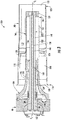
FIG. 3 is a cross sectional side view of an exemplary fuel nozzle as may incorporate one or more embodiments of the present disclosure; -
FIG. 4 is an enlarged isometric view of a tip body of the fuel nozzle as shown inFIG. 3 according to at least one embodiment of the present disclosure; -
FIG. 5 is an enlarge isometric view of a portion of the fuel nozzle as shown inFIG. 3 , according to at least one embodiment of the present disclosure; -
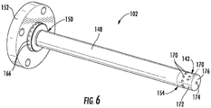
FIG. 6 is a perspective side view of a gas-only cartridge according to at least one embodiment of the present disclosure; -
FIG. 7 is an enlarged cross sectional side view of a portion of the fuel nozzle and the gas-only cartridge mounted to an end cover of a combustor according to at least one embodiment of the present disclosure; -
FIG. 8 provides a flow schematic of the fuel nozzle as shown isFIG. 3 according to at least one embodiment of the present disclosure; and -
FIG. 9 is a flow schematic of a portion of the fuel nozzle shown inFIG. 8 . - Reference will now be made in detail to present embodiments of the disclosure, one or more examples of which are illustrated in the accompanying drawings. The detailed description uses numerical and letter designations to refer to features in the drawings. Like or similar designations in the drawings and description have been used to refer to like or similar parts of the disclosure.
- As used herein, the terms "first", "second", and "third" may be used interchangeably to distinguish one component from another and are not intended to signify location or importance of the individual components. The terms "upstream" and "downstream" refer to the relative direction with respect to fluid flow in a fluid pathway. For example, "upstream" refers to the direction from which the fluid flows, and "downstream" refers to the direction to which the fluid flows. The term "radially" refers to the relative direction that is substantially perpendicular to an axial centerline of a particular component, and the term "axially" refers to the relative direction that is substantially parallel and/or coaxially aligned to an axial centerline of a particular component.
- The terminology used herein is for the purpose of describing particular embodiments only and is not intended to be limiting. As used herein, the singular forms "a", "an" and "the" are intended to include the plural forms as well, unless the context clearly indicates otherwise. It will be further understood that the terms "comprises" and/or "comprising," when used in this specification, specify the presence of stated features, integers, steps, operations, elements, and/or components, but do not preclude the presence or addition of one or more other features, integers, steps, operations, elements, components, and/or groups thereof.
- Each example is provided by way of explanation, not limitation. In fact, it will be apparent to those skilled in the art that modifications and variations can be made without departing from the scope or spirit thereof. For instance, features illustrated or described as part of one embodiment may be used on another embodiment to yield a still further embodiment. Thus, it is intended that the present disclosure covers such modifications and variations as come within the scope of the appended claims and their equivalents. Although exemplary embodiments of the present disclosure will be described generally in the context of a fuel nozzle for a land based power generating gas turbine combustor for purposes of illustration, one of ordinary skill in the art will readily appreciate that embodiments of the present disclosure may be applied to any style or type of combustor for a turbomachine and are not limited to combustors or combustion systems for land based power generating gas turbines unless specifically recited in the claims.
- Referring now to the drawings,
FIG. 1 illustrates a schematic diagram of anexemplary gas turbine 10. Thegas turbine 10 generally includes aninlet section 12, acompressor 14 disposed downstream of theinlet section 12, acombustion system 16 including at least onecombustor 18 disposed downstream of thecompressor 14, aturbine 20 disposed downstream of thecombustor 18 and anexhaust section 22 disposed downstream of theturbine 20. Additionally, thegas turbine 10 may include one ormore shafts 24 that couple thecompressor 14 to theturbine 20. - During operation,
air 26 flows through theinlet section 12 and into thecompressor 14 where theair 26 is progressively compressed, thus providingcompressed air 28 to thecombustor 18.Fuel 30 from afuel supply 32 is injected into thecombustor 18, mixed with a portion of thecompressed air 28 and burned to producecombustion gases 34. Thecombustion gases 34 flow from thecombustor 18 into theturbine 20, wherein energy (kinetic and/or thermal) is transferred from thecombustion gases 34 to rotor blades (not shown), thus causingshaft 24 to rotate. The mechanical rotational energy may then be used for various purposes such as to power thecompressor 14 and/or to generate electricity. Thecombustion gases 34 exiting theturbine 20 may then be exhausted from thegas turbine 10 via theexhaust section 22. - As shown in
FIG. 2 , thecombustor 18 may be at least partially surrounded anouter casing 36 such as a compressor discharge casing. Theouter casing 36 may at least partially define ahigh pressure plenum 38 that at least partially surrounds various components of thecombustor 18. Thehigh pressure plenum 38 may be in fluid communication with the compressor 16 (FIG. 1 ) so as to receive thecompressed air 28 therefrom. Anend cover 40 may be coupled to theouter casing 36. In particular embodiments, theouter casing 36 and theend cover 40 may at least partially define a head end volume orportion 42 of thecombustor 18. In particular embodiments, thehead end portion 42 is in fluid communication with thehigh pressure plenum 38 and/or thecompressor 14. One or more liners orducts 44 may at least partially define a combustion chamber orzone 46 for combusting the fuel-air mixture and/or may at least partially define ahot gas path 48 through the combustor for directing thecombustion gases 34 towards an inlet to theturbine 20. - In various embodiments, as shown in
FIG. 2 , thecombustor 18 includes one ormore fuel nozzles 100 coupled to theend cover 40 and extending towards thecombustion chamber 46. Various embodiments of thecombustor 18 may include different numbers and arrangements fuelnozzles 100 and is not limited to any particular number of fuel nozzles unless otherwise specified in the claims. For example, in particular configurations the one ormore fuel nozzles 100 may include multiple fuel nozzles annularly arranged about a center fuel nozzle. -
FIG. 3 shows anexemplary fuel nozzle 100 having a gas-only cartridge 102, according to at least one embodiment of the present disclosure. In at least one embodiment, thefuel nozzle 100 includes abase portion 104, acenter body 106 having an annular or tube shape, an outer sleeve orburner tube 108 that extends circumferentially around at least a portion of thecenter body 106 and a plurality of turningvanes 110 that extend between thecenter body 106 and theouter sleeve 108. The turningvanes 110 are disposed within a primarypremix air passage 112 which is defined between thecenter body 106 and theouter sleeve 108. Thecenter body 106 may be formed from one or more sleeves ortubes 114 coaxially aligned with thebase portion 104 along a longitudinal axis or axial centerline of thefuel nozzle 100. - An
upstream end portion 116 of theouter sleeve 108 may at least partially define aninlet 118 to the primarypremix air passage 112 and adownstream end portion 120 of theouter sleeve 108 may at least partially define anoutlet 122 of the primarypremix air passage 112. In at least one embodiment, theinlet 118 is in fluid communication with the head end 42 (FIG. 2 ) of thecombustor 18. Thebase portion 104 may be connected to an inner surface of theend cover 40 via mechanical fasteners or by other connecting means. In particular embodiments, thebase portion 104, thecenter body 106 and theouter sleeve 108 are coaxially aligned along the longitudinal axis of thefuel nozzle 100. - In one embodiment, an inner sleeve 124 may extend axially within the
base portion 104 and/or at least a portion of thecenter body 106 and may at least partially surround a portion of the gas-only cartridge 102. The inner sleeve 124 may at least partially define a fuel circuit or passage 126 for providing fuel to a plurality offuel ports 128 disposed/defined along one or more of the turningvanes 110. The fuel circuit 126 may be in fluid communication with one ormore fuel circuits 130 defined in theend cover 40. Thefuel ports 128 are in fluid communication with the primarypremix air passage 112. In one embodiment, the fuel circuit 126 may be at least partially defined between a portion of the gas-only cartridge 102 and the inner sleeve 124. - In various embodiments, a
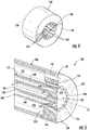
tip body 132 is disposed at and/or defines adownstream end 134 of thecenter body 106.FIG. 4 provides an isometric view of thetip body 132 according to at least one embodiment of the present disclosure.FIG. 5 provides a perspective cross sectional view of a portion of thefuel nozzle 100 including a portion of thecenter body 106 including thetip body 132 and a portion of the gas-only cartridge 102 according to at least one embodiment of the present disclosure. As shown inFIGS. 4 and 5 , thetip body 132 includes an upstream side orsurface 136 axially spaced from a downstream side orsurface 138. Thetip body 132 defines an opening 140 (FIG. 4 ) that extends through theupstream surface 136 and thedownstream surface 138. As shown inFIG. 5 , theopening 140 may be sized to allow afuel distribution tip 142 of the gas-only cartridge 102 to extend at least partially therethrough. - In various embodiments, as shown in
FIG. 4 , aninner surface 144 of thetip body 132 includes and/or defines a plurality of slots, grooves orchannels 146 annularly arranged about theopening 140. In particular embodiments, eachchannel 146 extends through theupstream surface 136 and thedownstream surface 138 of thetip body 132 and defines a respective flow path through thetip body 132. Thechannels 146 may have any cross sectional shape and the particular cross sectional shape of thechannels 146 is not limited to a particular cross sectional shape unless otherwise recited in the claims. - The
channels 146 may have the same cross sectional shape or may have different cross sectional shapes. In one embodiment, as shown inFIGS. 4 and 5 , one or more of thechannels 146 may have a substantially "U" cross sectional shape. Other cross sectional shapes may include a "C" or horseshoe shape where walls of eachchannel 146 meet or engage with the cartridge past perpendicular. In particular embodiments, as shown in dashed lines ofFIG. 5 , one or more of thechannels 146 may be angled with respect to the axial centerline of thefuel nozzle 100. In one embodiment, thechannels 146 may be oriented such as in a helical pattern, so as to impart angular swirl to air and/or a fuel and air mixture flowing through thechannels 146. In one embodiment, one or more of thechannels 146 may be oriented so as direct a flow of fuel-air mixture radially outwardly from the axial centerline towards theouter sleeve 108. In at least one embodiment, thetip body 132 may include and or define a plurality of circumferentially spaced cooling passages, as indicated by dashedlines 147, annularly arranged about or radially outwardly from thechannels 146. Thecooling passages 147 may provide for fluid communication through theupstream surface 136 and thedownstream surface 138 of thetip body 132. -
FIG. 6 provides a perspective side view of the gas-only cartridge 102 according to at least one embodiment of the present disclosure. In at least one embodiment, as shown inFIG. 6 , the gas-only cartridge 102 includes anouter tube 148. Theouter tube 148 may include afirst end 150 that is coupled to abase flange 152 and asecond end 154 that connected to and/or that at least partially defines thefuel distribution tip 142. As shown inFIG. 3 , thebase flange 152 may be formed to connect to an outer surface of theend cover 40 and theouter tube 148 may extend through the end cover 40 from thebase flange 152. As shown inFIG. 3 , when installed into thefuel nozzle 100, theouter tube 148 of the gas-only cartridge 102 and thecenter body 106 at least partially define a secondarypremix air passage 156 therebetween. - As shown in
FIGS. 3 and5 , the gas-only cartridge 102 further includes aninner tube 158 that extends axially within theouter tube 148. Theouter tube 148 is radially spaced from theinner tube 158 so as to define afuel passage 160 therebetween. In particular embodiments theinner tube 148 defines anair passage 162 within the gas-only cartridge 102. -
FIG. 7 provides an enlarged cross sectional side view of a portion of the gas-only cartridge 102 as shown inFIG. 3 , including a portion of thebase flange 152 and a portion of theend cover 40 according to at least one embodiment. As shown inFIG. 7 , thebase flange 152 and/or theend cover 40 may at least partially define afuel circuit 164 for providing a gaseous fuel to thefuel passage 160 of the gas-only cartridge 102. In particular embodiments, as shown inFIGS. 6 and7 , thebase flange 152 may define a plurality of circumferentially spacedapertures 166 that provide for fluid communication between thefuel circuit 164 and thefuel passage 160. In particular embodiments, thebase flange 152 may define one or more air circuits for providing a purge or cooling medium to theair passage 162 of the gas-only cartridge 102. - In various embodiments, as shown in
FIGS. 5 and6 , thefuel distribution tip 142 incudes and/or defines a plurality offuel ports 170 circumferentially spaced about thefuel distribution tip 142. Thefuel ports 170 provide for fluid communication between thefuel passage 160 and one or more of thechannels 146. In one embodiment, anouter surface 172 of thefuel distribution tip 142 and theinner surface 144 of thetip body 132 form multiple seals therebetween so as to at least partially fluidly isolate eachchannel 146 from circumferentiallyadjacent channels 146. - In various embodiments, as shown in
FIG. 5 , eachfuel port 170 is aligned with and/or in fluid communication with one correspondingchannel 146. In particular embodiments, one or more of thefuel ports 170 may be oriented so as to direct a flow of a gaseous fuel radially outwardly from theouter surface 172 of thefuel distribution tip 142 into eachrespective channel 146 in a direction that is substantially perpendicular to a flow of compressed air flowing through thechannel 146. In particular embodiments, one or more of thefuel ports 170 may be angled with respect to the axial centerline of thefuel nozzle 100. For example, one or more of thefuel ports 170 may be angled into or towards theupstream surface 136 of thetip body 132. In addition or in the alternative, in particular embodiments, one or more of thefuel ports 170 may be angled towards thedownstream surface 138 of thetip body 132. In one embodiment, as shown inFIG. 6 , at least onefuel port 170 is axially offset from circumferentiallyadjacent fuel ports 170 with respect to an axial centerline of the gas-only cartridge 102. - In one embodiment, as shown in
FIGS. 5 and6 , thefuel distribution tip 142 includes and/or defines at least oneaperture 174 that provides for fluid communication from theair passage 162 through thefuel distribution tip 142. Theaperture 174 generally extends through adownstream surface 176 of thefuel distribution tip 142. -
FIG. 8 is a flow diagram of thefuel nozzle 100 as shown inFIG. 3 , according to at least one embodiment of the present disclosure.FIG. 9 provides an enlarged cross sectional side view of a portion of thefuel nozzle 100 as shown inFIG. 8 , including a portion of thecenter body 106, thetip body 132 and a portion of the gas-only cartridge 102. During premix operation of thefuel nozzle 100, as shown in schematically inFIG. 8 , a first portion ofcompressed air 200 such as thecompressed air 28 from the compressor 14 (FIG. 1 ) enters theinlet 118 of the primarypremix air passage 112. The turningvanes 110 impart angular swirl to the first portion ofcompressed air 200.Gaseous fuel 202 flows into thebase portion 104 and is routed to the turningvane 110 where it is injected into the first portion ofcompressed air 200 via the plurality offuel ports 128, thereby producing a primary fuel-air mixture downstream from the turningvanes 110. The primary fuel-air mixture 204 flows from theouter sleeve 108 into the combustion chamber or zone 46 (FIG. 2 ) via theoutlet 122. - A second portion of
compressed air 206 may be routed into the secondarypremix air passage 156. In particular embodiments, the second portion ofcompressed air 206 is routed from the primarypremix air passage 112 through one or more passages or holes defined in and/or by thecenter body 106 and into the secondarypremix air passage 156. As shown inFIGS. 8 and 9 , the second portion ofcompressed air 206 is then routed into each of thechannels 146 of thetip body 132.Gaseous fuel 208 flows from the fuel circuit 164 (FIG. 8 ) and into thefuel passage 160 of the gas-only cartridge 102 via theapertures 166. - As shown in
FIG. 9 , thegaseous fuel 208 flows into each of therespective channels 146 viafuel ports 170. The second portion ofcompressed air 206 in eachrespective channel 146 mixes with thegaseous fuel 208 so as to provide a secondary fuel-air mixture 210 to thecombustion chamber 46. - In particular embodiments, a purge or cooling medium 212 such as compressed air flows into and through the
air passage 162. Thepurge medium 212 exits theair passage 162 via theaperture 174 or a plurality ofapertures 174, thereby cooling a downstream surface of thefuel distribution tip 142 of the gas-only cartridge 102. In particular embodiments, a portion of the second portion ofcompressed air 206 may be routed through the cooling passages 147 (FIG. 5 ), thereby providing cooling to thedownstream surface 138 of thetip body 132. - The
fuel nozzle 100, particularly the gas-only cartridge 102 as described herein provides various technical benefits over existing dual fueltype fuel nozzles 100. The gas-only cartridge 102 replaces the existing blank or purge air only cartridges with a premixed fuel injection design. The gas-only cartridge 102 as described herein premixes theair 206 with thegaseous fuel 208, thereby improving emissions output without sacrificing durability. Additionally, the separate fuel /air premixing provided by the gas onlycartridge 102 may enhance flame stability and improve operability by reducing the tendency for lean blowout and decreasing combustion thermo-acoustic instabilities, also known as dynamics. The gas-only cartridge 102 as described herein maintains adequate cooling of thetip body 132 may be retrofitted into existing combustors with minimal changes and is compatible for a dual fuel application in that the gas-only cartridge 102 may be removed and replaced with a liquid cartridge. - This written description uses examples to disclose the invention and also to enable any person skilled in the art to practice the invention, including making and using any devices or systems and performing any incorporated methods. The patentable scope of the invention is defined by the claims, and may include other examples that occur to those skilled in the art. Such other examples are intended to be within the scope of the claims if they include structural elements that do not differ from the literal language of the claims, or if they include equivalent structural elements with insubstantial differences from the literal language of the claims.
- Various aspects and embodiments of the present invention are defined by the following numbered clauses:
- 1. A gas-only cartridge for a fuel nozzle, the gas-only cartridge comprising:
- a flange defining a plurality of apertures for receiving a gaseous fuel;
- an outer tube coupled to the flange and extending axially outwardly from the flange;
- an inner tube extending axially within the outer tube, wherein the inner tube and the outer tube define a fuel passage therebetween, wherein the fuel passage is in fluid communication with the plurality of apertures of the flange; and
- a fuel distribution tip disposed at a downstream end of the gas-only cartridge, the fuel distribution tip defining a plurality of fuel ports circumferentially spaced along and annularly arranged about an outer surface of the fuel distribution tip, wherein the fuel ports are in fluid communication with the fuel passage.
- 2. The gas-only cartridge as in clause 1, wherein the inner tube at least partially defines an air passage within the gas-only cartridge.
- 3. The gas-only cartridge as in any preceding clause, wherein the fuel distribution tip defines an aperture disposed along a downstream surface of the fuel distribution tip, wherein the aperture is in fluid communication with the air passage.
- 4. The gas-only cartridge as in any preceding clause, wherein the flange at least partially defines at least one air circuit, wherein the air circuit is in fluid communication with the air passage.
- 5. The gas-only cartridge as in any preceding clause, wherein at least one fuel port of the plurality of fuel ports is axially offset from a circumferentially adjacent fuel port.
- 6. The gas-only cartridge as in any preceding clause, wherein the flange is formed to connect to an outer surface of an end cover of a gas turbine combustor.
- 7. A fuel nozzle, comprising:
- a center body;
- a tip body disposed at a downstream end of the center body, the tip body defining an opening that extends axially through the tip body and including a plurality of channels circumferentially spaced and position along an inner surface of the tip body within the opening, wherein each channel defines a flow passage through an upstream surface and a downstream surface of the tip body; and
- a gas-only cartridge that extends axially within the center body, the gas-only cartridge having an outer tube, an inner tube extending axially within the outer tube fuel and a fuel passage defined therebetween, wherein the outer tube and the centerbody define a secondary premix air passage therebetween, the gas-only cartridge further comprising a fuel distribution tip that extends at least partially through the opening of the tip body, the fuel distribution tip including a plurality of circumferentially spaced fuel ports in fluid communication with the fuel passage, wherein each fuel port is in fluid communication with a respective channel of the tip body and each channel is in fluid communication with the secondary premix air passage.
- 8. The fuel nozzle as in any preceding clause, wherein each channel of the plurality of channels is "U" shaped.
- 9. The fuel nozzle as in any preceding clause, wherein the plurality of channels is formed in a helical pattern along the inner surface of the tip body between the upstream surface and the downstream surface of the tip body.
- 10. The fuel nozzle as in any preceding clause, wherein the inner surface of the tip body forms a seal against an outer surface of the fuel distribution tip between each circumferentially adjacent channel of the plurality of channels.
- 11. The fuel nozzle as in any preceding clause, wherein the inner tube of the gas-only cartridge at least partially defines an air passage within the gas-only cartridge.
- 12. The fuel nozzle as in any preceding clause, wherein the fuel distribution tip of the gas-only cartridge defines an aperture disposed along a downstream surface of the fuel distribution tip, wherein the aperture is in fluid communication with the air passage.
- 13. The fuel nozzle as in any preceding clause, wherein the flange of the gas-only cartridge at least partially defines at least one air circuit, wherein the air circuit is in fluid communication with the air passage.
- 14. The fuel nozzle as in any preceding clause, wherein at least one fuel port of the plurality of fuel ports of the fuel distribution tip is axially offset from a circumferentially adjacent fuel port of the fuel distribution tip.
- 15. The fuel nozzle as in any preceding clause, wherein the flange of the gas-only cartridge is formed to connect to an outer surface of an end cover of a gas turbine combustor.
- 16. A combustor, comprising:
- an end cover coupled to an outer casing;
- a fuel nozzle having a base portion coupled to one side of the end cover, the fuel nozzle comprising:
- a center body coupled to and coaxially aligned with the base portion;
- a tip body disposed at a downstream end of the center body, the tip body defining an opening that extends axially through the tip body and including a plurality of channels circumferentially spaced and position along an inner surface of the tip body within the opening, wherein each channel defines a flow passage through an upstream surface and a downstream surface of the tip body; and
- a gas-only cartridge that extends axially within the center body, the gas-only cartridge having an outer tube, an inner tube extending axially within the outer tube fuel and a fuel passage defined therebetween, wherein the outer tube and the centerbody define a secondary premix air passage therebetween, the gas-only cartridge further comprising a fuel distribution tip that extends at least partially through the opening of the tip body, the fuel distribution tip including a plurality of circumferentially spaced fuel ports in fluid communication with the fuel passage, wherein each fuel port is in fluid communication with a respective channel of the tip body and each channel is in fluid communication with the secondary premix air passage.
- 17. The gas turbine as in any preceding clause, wherein the plurality of channels is formed in a helical pattern along the inner surface of the tip body between the upstream surface and the downstream surface of the tip body.
- 18. The fuel nozzle as in any preceding clause, wherein the inner surface of the tip body forms multiple seals against an outer surface of the fuel distribution tip between each circumferentially adjacent channel of the plurality of channels.
- 19. The gas turbine as in any preceding clause, wherein the inner tube of the gas-only cartridge at least partially defines an air passage within the gas-only cartridge, wherein the fuel distribution tip of the gas-only cartridge defines at least one aperture disposed along a downstream surface of the fuel distribution tip, and wherein the aperture is in fluid communication with the air passage.
- 20. The gas turbine as in any preceding clause, wherein at least one fuel port of the plurality of fuel ports of the fuel distribution tip is axially offset from a circumferentially adjacent fuel port of the fuel distribution tip.
Claims (15)
- A gas-only cartridge (102) for a fuel nozzle (100), the gas-only cartridge (102) comprising:a flange (152) defining a plurality of apertures (166) for receiving a gaseous fuel;an outer tube (148) coupled to the flange (152) and extending axially outwardly from the flange (152);an inner tube (158) extending axially within the outer tube (148), wherein the inner tube (158) and the outer tube (148) define a fuel passage (160) therebetween, wherein the fuel passage (160) is in fluid communication with the plurality of apertures (166) of the flange (152); anda fuel distribution tip (142) disposed at a downstream end of the gas-only cartridge (102), the fuel distribution tip (142) defining a plurality of fuel ports (170) circumferentially spaced along and annularly arranged about an outer surface of the fuel distribution tip (142), wherein the fuel ports (170) are in fluid communication with the fuel passage (160).
- The gas-only cartridge (102) as in claim 1, wherein the inner tube (158) at least partially defines an air passage (162) within the gas-only cartridge (102).
- The gas-only cartridge (102) as in claim 2, wherein the fuel distribution tip (142) defines an aperture (174) disposed along a downstream surface (138) of the fuel distribution tip (142), wherein the aperture (174) is in fluid communication with the air passage (162).
- The gas-only cartridge (102) as in claim 2 or 3, wherein the flange (152) at least partially defines at least one air circuit (168), wherein the air circuit (168) is in fluid communication with the air passage (162).
- The gas-only cartridge (102) as in any preceding claim, wherein at least one fuel port (170) of the plurality of fuel ports (170) is axially offset from a circumferentially adjacent fuel port (170).
- The gas-only cartridge (102) as in any preceding claim, wherein the flange (152) is formed to connect to an outer surface of an end cover of a gas turbine combustor.
- A fuel nozzle (100), comprising:a center body (106);a tip body (132) disposed at a downstream end of the center body (106), the tip body (132) defining an opening (140) that extends axially through the tip body (132) and including a plurality of channels (146) circumferentially spaced and position along an inner surface (144) of the tip body (132) within the opening (140), wherein each channel (146) defines a flow passage through an upstream surface (136) and a downstream surface (138) of the tip body (132); anda gas-only cartridge (102) that extends axially within the center body (106), the gas-only cartridge (102) having an outer tube (148), an inner tube (158) extending axially within the outer tube (148) fuel and a fuel passage (160) defined therebetween, wherein the outer tube (148) and the centerbody define a secondary premix air passage (162) therebetween, the gas-only cartridge (102) further comprising a fuel distribution tip (142) that extends at least partially through the opening (140) of the tip body (132), the fuel distribution tip (142) including a plurality of circumferentially spaced fuel ports (170) in fluid communication with the fuel passage (160), wherein each fuel port (170) is in fluid communication with a respective channel (146) of the tip body (132) and each channel (146) is in fluid communication with the secondary premix air passage (162).
- The fuel nozzle (100) as in claim 7, wherein each channel (146) of the plurality of channels (146) is "U" shaped.
- The fuel nozzle (100) as in claim 7 or 8, wherein the plurality of channels (146) is formed in a helical pattern along the inner surface (144) of the tip body (132) between the upstream surface (136) and the downstream surface (138) of the tip body (132).
- The fuel nozzle (100) as in claim 7, 8 or 9, wherein the inner surface (144) of the tip body (132) forms a seal against an outer surface of the fuel distribution tip (142) between each circumferentially adjacent channel (146) of the plurality of channels (146).
- The fuel nozzle (100) as in any of claims 7 to 10, wherein the inner tube (158) of the gas-only cartridge (102) at least partially defines an air passage (162) within the gas-only cartridge (102).
- The fuel nozzle (100) as in claim 11, wherein the fuel distribution tip (142) of the gas-only cartridge (102) defines an aperture (174) disposed along a downstream surface (138) of the fuel distribution tip (142), wherein the aperture (174) is in fluid communication with the air passage (162).
- The fuel nozzle (100) as in claim 11 or 12, wherein the flange (152) of the gas-only cartridge (102) at least partially defines at least one air circuit (168), wherein the air circuit (168) is in fluid communication with the air passage (162).
- The fuel nozzle (100) as in any of claims 7 to 13, wherein at least one fuel port (170) of the plurality of fuel ports (170) of the fuel distribution tip (142) is axially offset from a circumferentially adjacent fuel port (170) of the fuel distribution tip (142).
- The fuel nozzle (100) as in any of claims 7 to 14, wherein the flange (152) of the gas-only cartridge (102) is formed to connect to an outer surface of an end cover (40) of a gas turbine combustor.
Applications Claiming Priority (1)
| Application Number | Priority Date | Filing Date | Title |
|---|---|---|---|
| US15/046,482 US10228140B2 (en) | 2016-02-18 | 2016-02-18 | Gas-only cartridge for a premix fuel nozzle |
Publications (2)
| Publication Number | Publication Date |
|---|---|
| EP3211318A2 true EP3211318A2 (en) | 2017-08-30 |
| EP3211318A3 EP3211318A3 (en) | 2017-11-15 |
Family
ID=58094244
Family Applications (1)
| Application Number | Title | Priority Date | Filing Date |
|---|---|---|---|
| EP17156619.3A Pending EP3211318A3 (en) | 2016-02-18 | 2017-02-17 | Gas-only cartridge for a premix fuel nozzle |
Country Status (4)
| Country | Link |
|---|---|
| US (1) | US10228140B2 (en) |
| EP (1) | EP3211318A3 (en) |
| JP (1) | JP6900198B2 (en) |
| CN (1) | CN107091485B (en) |
Families Citing this family (7)
| Publication number | Priority date | Publication date | Assignee | Title |
|---|---|---|---|---|
| US10215415B2 (en) | 2015-09-23 | 2019-02-26 | General Electric Company | Premix fuel nozzle assembly cartridge |
| US10415833B2 (en) * | 2017-02-16 | 2019-09-17 | General Electric Company | Premixer for gas turbine combustor |
| CN107702147B (en) * | 2017-09-05 | 2020-07-14 | 中国联合重型燃气轮机技术有限公司 | Fuel nozzle for gas turbine |
| CN108443912B (en) * | 2018-02-08 | 2023-10-03 | 中国船舶重工集团公司第七0三研究所 | Self-priming air-assisted atomization dual-fuel nozzle |
| KR102026973B1 (en) * | 2019-02-28 | 2019-09-30 | 천지산업주식회사 | Pilot Nozle for gas turbine product method |
| KR102382634B1 (en) * | 2020-12-22 | 2022-04-01 | 두산중공업 주식회사 | Nozzle for combustor, combustor, and gas turbine including the same |
| KR102607178B1 (en) * | 2022-01-18 | 2023-11-29 | 두산에너빌리티 주식회사 | Nozzle for combustor, combustor, and gas turbine including the same |
Family Cites Families (32)
| Publication number | Priority date | Publication date | Assignee | Title |
|---|---|---|---|---|
| US4154056A (en) * | 1977-09-06 | 1979-05-15 | Westinghouse Electric Corp. | Fuel nozzle assembly for a gas turbine engine |
| US5003766A (en) * | 1984-10-10 | 1991-04-02 | Paul Marius A | Gas turbine engine |
| CH672541A5 (en) | 1986-12-11 | 1989-11-30 | Bbc Brown Boveri & Cie | |
| EP0276696B1 (en) * | 1987-01-26 | 1990-09-12 | Siemens Aktiengesellschaft | Hybrid burner for premix operation with gas and/or oil, particularly for gas turbine plants |
| US5408825A (en) * | 1993-12-03 | 1995-04-25 | Westinghouse Electric Corporation | Dual fuel gas turbine combustor |
| US5408830A (en) * | 1994-02-10 | 1995-04-25 | General Electric Company | Multi-stage fuel nozzle for reducing combustion instabilities in low NOX gas turbines |
| US5873237A (en) * | 1997-01-24 | 1999-02-23 | Westinghouse Electric Corporation | Atomizing dual fuel nozzle for a combustion turbine |
| US6446439B1 (en) * | 1999-11-19 | 2002-09-10 | Power Systems Mfg., Llc | Pre-mix nozzle and full ring fuel distribution system for a gas turbine combustor |
| US6698207B1 (en) * | 2002-09-11 | 2004-03-02 | Siemens Westinghouse Power Corporation | Flame-holding, single-mode nozzle assembly with tip cooling |
| FR2875584B1 (en) * | 2004-09-23 | 2009-10-30 | Snecma Moteurs Sa | EFFERVESCENCE INJECTOR FOR AEROMECHANICAL AIR / FUEL INJECTION SYSTEM IN A TURBOMACHINE COMBUSTION CHAMBER |
| FR2891314B1 (en) * | 2005-09-28 | 2015-04-24 | Snecma | INJECTOR ARM ANTI-COKEFACTION. |
| US20080276622A1 (en) * | 2007-05-07 | 2008-11-13 | Thomas Edward Johnson | Fuel nozzle and method of fabricating the same |
| US20090165436A1 (en) | 2007-12-28 | 2009-07-02 | General Electric Company | Premixed, preswirled plasma-assisted pilot |
| US20100024425A1 (en) * | 2008-07-31 | 2010-02-04 | General Electric Company | Turbine engine fuel nozzle |
| US8261554B2 (en) * | 2008-09-17 | 2012-09-11 | General Electric Company | Fuel nozzle tip assembly |
| US8752389B2 (en) * | 2008-11-05 | 2014-06-17 | General Electric Company | Fuel nozzle assembly for use with a gas turbine engine and method of assembling same |
| US8079218B2 (en) * | 2009-05-21 | 2011-12-20 | General Electric Company | Method and apparatus for combustor nozzle with flameholding protection |
| US8468831B2 (en) * | 2009-07-13 | 2013-06-25 | General Electric Company | Lean direct injection for premixed pilot application |
| US8555648B2 (en) * | 2010-02-12 | 2013-10-15 | General Electric Company | Fuel injector nozzle |
| US20110314827A1 (en) * | 2010-06-24 | 2011-12-29 | General Electric Company | Fuel nozzle assembly |
| US8418469B2 (en) * | 2010-09-27 | 2013-04-16 | General Electric Company | Fuel nozzle assembly for gas turbine system |
| US8464537B2 (en) * | 2010-10-21 | 2013-06-18 | General Electric Company | Fuel nozzle for combustor |
| US9010119B2 (en) * | 2010-11-03 | 2015-04-21 | General Electric Company | Premixing nozzle |
| US20120125004A1 (en) * | 2010-11-19 | 2012-05-24 | General Electric Company | Combustor premixer |
| JP5631223B2 (en) * | 2011-01-14 | 2014-11-26 | 三菱重工業株式会社 | Fuel nozzle, gas turbine combustor including the same, and gas turbine including the same |
| US20120204571A1 (en) * | 2011-02-15 | 2012-08-16 | General Electric Company | Combustor and method for introducing a secondary fluid into a fuel nozzle |
| US8899494B2 (en) * | 2011-03-31 | 2014-12-02 | General Electric Company | Bi-directional fuel injection method |
| JP2015505596A (en) * | 2012-02-01 | 2015-02-23 | ゼネラル・エレクトリック・カンパニイ | Gas turbine liquid fuel nozzle and method of injecting fuel into a gas turbine combustor |
| US20130219899A1 (en) * | 2012-02-27 | 2013-08-29 | General Electric Company | Annular premixed pilot in fuel nozzle |
| US9500370B2 (en) * | 2013-12-20 | 2016-11-22 | General Electric Company | Apparatus for mixing fuel in a gas turbine nozzle |
| US11015809B2 (en) | 2014-12-30 | 2021-05-25 | General Electric Company | Pilot nozzle in gas turbine combustor |
| US9982892B2 (en) * | 2015-04-16 | 2018-05-29 | General Electric Company | Fuel nozzle assembly including a pilot nozzle |
-
2016
- 2016-02-18 US US15/046,482 patent/US10228140B2/en active Active
-
2017
- 2017-02-08 JP JP2017020815A patent/JP6900198B2/en active Active
- 2017-02-17 EP EP17156619.3A patent/EP3211318A3/en active Pending
- 2017-02-17 CN CN201710086453.4A patent/CN107091485B/en active Active
Non-Patent Citations (1)
| Title |
|---|
| None |
Also Published As
| Publication number | Publication date |
|---|---|
| EP3211318A3 (en) | 2017-11-15 |
| JP6900198B2 (en) | 2021-07-07 |
| CN107091485A (en) | 2017-08-25 |
| US20170241644A1 (en) | 2017-08-24 |
| CN107091485B (en) | 2021-06-11 |
| JP2017146087A (en) | 2017-08-24 |
| US10228140B2 (en) | 2019-03-12 |
Similar Documents
| Publication | Publication Date | Title |
|---|---|---|
| US10641176B2 (en) | Combustion system with panel fuel injector | |
| US10228140B2 (en) | Gas-only cartridge for a premix fuel nozzle | |
| US8904798B2 (en) | Combustor | |
| US9982892B2 (en) | Fuel nozzle assembly including a pilot nozzle | |
| US9714767B2 (en) | Premix fuel nozzle assembly | |
| EP3282191B1 (en) | Pilot premix nozzle and fuel nozzle assembly | |
| CN106066048B (en) | Premix pilot nozzle | |
| EP3376109B1 (en) | Dual-fuel fuel nozzle with liquid fuel tip | |
| US20170082290A1 (en) | Premix fuel nozzle assembly cartridge | |
| US10030869B2 (en) | Premix fuel nozzle assembly | |
| US10823420B2 (en) | Pilot nozzle with inline premixing | |
| EP3187783A1 (en) | Fuel nozzle assembly having a premix flame stabilizer | |
| EP3314167B1 (en) | Fuel nozzle assembly having a premix flame stabilizer | |
| US20180340689A1 (en) | Low Profile Axially Staged Fuel Injector | |
| US10955141B2 (en) | Dual-fuel fuel nozzle with gas and liquid fuel capability |
Legal Events
| Date | Code | Title | Description |
|---|---|---|---|
| PUAI | Public reference made under article 153(3) epc to a published international application that has entered the european phase |
Free format text: ORIGINAL CODE: 0009012 |
|
| STAA | Information on the status of an ep patent application or granted ep patent |
Free format text: STATUS: THE APPLICATION HAS BEEN PUBLISHED |
|
| AK | Designated contracting states |
Kind code of ref document: A2 Designated state(s): AL AT BE BG CH CY CZ DE DK EE ES FI FR GB GR HR HU IE IS IT LI LT LU LV MC MK MT NL NO PL PT RO RS SE SI SK SM TR |
|
| AX | Request for extension of the european patent |
Extension state: BA ME |
|
| PUAL | Search report despatched |
Free format text: ORIGINAL CODE: 0009013 |
|
| AK | Designated contracting states |
Kind code of ref document: A3 Designated state(s): AL AT BE BG CH CY CZ DE DK EE ES FI FR GB GR HR HU IE IS IT LI LT LU LV MC MK MT NL NO PL PT RO RS SE SI SK SM TR |
|
| AX | Request for extension of the european patent |
Extension state: BA ME |
|
| RIC1 | Information provided on ipc code assigned before grant |
Ipc: F23R 3/36 20060101AFI20171010BHEP Ipc: F23D 14/58 20060101ALI20171010BHEP Ipc: F23D 17/00 20060101ALI20171010BHEP Ipc: F23R 3/28 20060101ALI20171010BHEP Ipc: F23R 3/46 20060101ALI20171010BHEP |
|
| STAA | Information on the status of an ep patent application or granted ep patent |
Free format text: STATUS: REQUEST FOR EXAMINATION WAS MADE |
|
| 17P | Request for examination filed |
Effective date: 20180515 |
|
| RBV | Designated contracting states (corrected) |
Designated state(s): AL AT BE BG CH CY CZ DE DK EE ES FI FR GB GR HR HU IE IS IT LI LT LU LV MC MK MT NL NO PL PT RO RS SE SI SK SM TR |
|
| STAA | Information on the status of an ep patent application or granted ep patent |
Free format text: STATUS: EXAMINATION IS IN PROGRESS |
|
| 17Q | First examination report despatched |
Effective date: 20200211 |
|
| STAA | Information on the status of an ep patent application or granted ep patent |
Free format text: STATUS: EXAMINATION IS IN PROGRESS |
|
| STAA | Information on the status of an ep patent application or granted ep patent |
Free format text: STATUS: EXAMINATION IS IN PROGRESS |
|
| RAP1 | Party data changed (applicant data changed or rights of an application transferred) |
Owner name: GENERAL ELECTRIC TECHNOLOGY GMBH |