EP2949855A1 - Door seal, door with door seal and method for manufacture thereof - Google Patents
Door seal, door with door seal and method for manufacture thereof Download PDFInfo
- Publication number
- EP2949855A1 EP2949855A1 EP15170085.3A EP15170085A EP2949855A1 EP 2949855 A1 EP2949855 A1 EP 2949855A1 EP 15170085 A EP15170085 A EP 15170085A EP 2949855 A1 EP2949855 A1 EP 2949855A1
- Authority
- EP
- European Patent Office
- Prior art keywords
- door
- housing
- groove
- door seal
- recess
- Prior art date
- Legal status (The legal status is an assumption and is not a legal conclusion. Google has not performed a legal analysis and makes no representation as to the accuracy of the status listed.)
- Granted
Links
Images


Classifications
-
- E—FIXED CONSTRUCTIONS
- E06—DOORS, WINDOWS, SHUTTERS, OR ROLLER BLINDS IN GENERAL; LADDERS
- E06B—FIXED OR MOVABLE CLOSURES FOR OPENINGS IN BUILDINGS, VEHICLES, FENCES OR LIKE ENCLOSURES IN GENERAL, e.g. DOORS, WINDOWS, BLINDS, GATES
- E06B7/00—Special arrangements or measures in connection with doors or windows
- E06B7/16—Sealing arrangements on wings or parts co-operating with the wings
- E06B7/18—Sealing arrangements on wings or parts co-operating with the wings by means of movable edgings, e.g. draught sealings additionally used for bolting, e.g. by spring force or with operating lever
- E06B7/20—Sealing arrangements on wings or parts co-operating with the wings by means of movable edgings, e.g. draught sealings additionally used for bolting, e.g. by spring force or with operating lever automatically withdrawn when the wing is opened, e.g. by means of magnetic attraction, a pin or an inclined surface, especially for sills
- E06B7/21—Sealing arrangements on wings or parts co-operating with the wings by means of movable edgings, e.g. draught sealings additionally used for bolting, e.g. by spring force or with operating lever automatically withdrawn when the wing is opened, e.g. by means of magnetic attraction, a pin or an inclined surface, especially for sills with sealing strip movable in plane of wing
-
- E—FIXED CONSTRUCTIONS
- E06—DOORS, WINDOWS, SHUTTERS, OR ROLLER BLINDS IN GENERAL; LADDERS
- E06B—FIXED OR MOVABLE CLOSURES FOR OPENINGS IN BUILDINGS, VEHICLES, FENCES OR LIKE ENCLOSURES IN GENERAL, e.g. DOORS, WINDOWS, BLINDS, GATES
- E06B7/00—Special arrangements or measures in connection with doors or windows
- E06B7/16—Sealing arrangements on wings or parts co-operating with the wings
- E06B7/18—Sealing arrangements on wings or parts co-operating with the wings by means of movable edgings, e.g. draught sealings additionally used for bolting, e.g. by spring force or with operating lever
- E06B7/20—Sealing arrangements on wings or parts co-operating with the wings by means of movable edgings, e.g. draught sealings additionally used for bolting, e.g. by spring force or with operating lever automatically withdrawn when the wing is opened, e.g. by means of magnetic attraction, a pin or an inclined surface, especially for sills
- E06B7/215—Sealing arrangements on wings or parts co-operating with the wings by means of movable edgings, e.g. draught sealings additionally used for bolting, e.g. by spring force or with operating lever automatically withdrawn when the wing is opened, e.g. by means of magnetic attraction, a pin or an inclined surface, especially for sills with sealing strip being moved to a retracted position by elastic means, e.g. springs
-
- E—FIXED CONSTRUCTIONS
- E06—DOORS, WINDOWS, SHUTTERS, OR ROLLER BLINDS IN GENERAL; LADDERS
- E06B—FIXED OR MOVABLE CLOSURES FOR OPENINGS IN BUILDINGS, VEHICLES, FENCES OR LIKE ENCLOSURES IN GENERAL, e.g. DOORS, WINDOWS, BLINDS, GATES
- E06B7/00—Special arrangements or measures in connection with doors or windows
- E06B7/16—Sealing arrangements on wings or parts co-operating with the wings
- E06B7/18—Sealing arrangements on wings or parts co-operating with the wings by means of movable edgings, e.g. draught sealings additionally used for bolting, e.g. by spring force or with operating lever
- E06B7/20—Sealing arrangements on wings or parts co-operating with the wings by means of movable edgings, e.g. draught sealings additionally used for bolting, e.g. by spring force or with operating lever automatically withdrawn when the wing is opened, e.g. by means of magnetic attraction, a pin or an inclined surface, especially for sills
- E06B2007/202—Actuator connected to wing frame
Definitions
- the invention relates to a door seal. Such seals are used to seal an opening between the door and a ground surface. Door seals prevent draught passing through under the door, increases fire safety and/or realizes sound insulation.
- An object of the invention is to obviate or at least alleviate the above stated problem and to provide a door seal which can be mounted in simple manner in a recess in the underside of a door.
- the door seal according to the invention can be placed easily in the recess of the door from the underside.
- the inner wall of the recess will press the resilient tongue in the direction of the side wall counter to the spring force of the tongue.
- the resilient tongue therefore pushes against the inner wall of the recess in the door and thus clamps the housing in the recess.
- Screws are not therefore required for mounting of the door seal in the recess.
- the door seal according to the invention can therefore be mounted in a door in a very short time. This is a particular advantage in the large-scale production of doors, wherein because of the invention a door seal can be mounted with relatively few operations.
- door' is understood in the context of the invention to mean a door leaf, i.e. that part which can move relative to a door frame.
- the resilient tongue extends inclining downward.
- the resilient tongue has an angle relative to the side wall.
- the outer end of the tongue points here in downward direction, i.e. in the direction of the sealing body. In use the outer end of the resilient tongue will point in the direction of the ground surface.
- the at least one side wall of the housing comprises a groove and the mounting means comprise a separate, substantially V-shaped element, wherein the resilient tongue forms a first leg of the substantially V-shaped element and a second leg of the substantially V-shaped element is placed in the groove.
- the legs of the V-shaped element can move resiliently relative to each other.
- the element with resilient tongue can therefore be produced in simple manner.
- the V-shaped element can be coupled to the housing by placing one of the legs in the groove in the side edge of the housing. Once the door seal has been placed in a recess of a door, the resilience will hold the V-shaped element in the groove.
- the groove comprises an edge for retaining the second leg of the V-shaped element behind the edge in the groove.
- the second leg of the V-shaped element is placed behind the edge of the groove, for instance by sliding the V-shaped element into the groove from the side of the housing. This achieves that the V-shaped element is also held in the groove prior to being mounted in the door.
- the resilient tongue and the housing are formed integrally and the resilient tongue is formed by a portion cut out of the at least one side wall.
- the tongue is for instance formed by making a portion cut out of the side wall and subsequently bending a part of the side wall so that a resilient tongue is formed.
- the resilient tongue has teeth on its outer end so that the tongue can engage in the door.
- the tongue can hereby bite into the inner wall of the recess so that a digging-in effect is achieved. This prevents a vertical displacement of the housing following placing in the recess.
- the toothed outer end will attach itself particularly well to wooden and plastic doors.
- a stop is mounted on at least one of the outer ends of the housing for the purpose of blocking sliding of the housing in a longitudinal direction.
- the resilient tongue holds the door seal in the recess, wherein vertical displacement is not possible, in some cases a horizontal displacement of the housing is not completely blocked. In such a situation the door seal can be displaced when sufficient force is exerted. Displacement in at least one longitudinal direction is blocked by providing a stop on at least one of the outer ends of the housing.
- both outer ends of the housing are provided with a stop.
- At least one stop is in that case preferably connected releasably to the housing, for instance by means of a screw.
- the releasable stop can be removed, after which the housing can be displaced in the direction of the other stop. Due to the presence of the resilient tongue some force will be necessary for this displacement.
- the door seal is for instance tapped out of the door using a hammer.
- the stop in which at least one side wall of the housing comprises a groove for receiving a substantially V-shaped element as described above, the stop can be embodied as a stop mountable in the groove.
- the stop mountable in the groove is preferably embodied as a separate part which can be snapped into the groove.
- the stop is for instance embodied as an element with at least one leg which can be pushed into the groove, and a side surface connecting to and lying substantially at a right angle to the at least one leg.
- the stop is fixed in the groove by sliding the stop with the at least one leg into the corresponding groove from the end surface of the housing.
- the side surface of the stop is situated on the end surface of the housing and extends beyond the side wall of the housing and/or beyond the upper side of the housing so that the side surface functions as stop surface for the purpose of preventing sliding of the housing in longitudinal direction.
- the leg preferably comprises a coupling means for co-action with a corresponding coupling means provided in the groove of the housing.
- the co-acting coupling means for instance comprise an opening and a protrusion.
- the protrusion is for instance embodied in the form of a stud.
- the leg preferably comprises a protrusion which fits into a corresponding opening or recess arranged in the groove of the housing.
- the leg is for instance embodied as a resilient tongue on which the protrusion is formed so that the stop can be attached to the housing by snapping the protrusion into the corresponding opening in the housing.
- Two of such stops are for instance provided so that a stop can be mounted in both grooves on either side of the housing.
- the stop mountable in the groove is alternatively embodied as an element with two legs so that each leg can be placed in another of the two grooves on either side of the housing.
- the groove is preferably provided with an edge for the purpose of retaining the stop mountable in the groove behind the edge.
- the invention further relates to a door comprising on its underside a recess in which a door seal as described above is provided.
- a groove is provided in the inner wall of the recess such that the resilient tongue can move back resiliently at the position of a groove in order to hold the housing in the recess.
- the resilient tongue functions as a kind of hook for holding the housing in the recess.
- the tongue will also have more or less of a clamping action.
- the door has a hinge side for connecting the door to a door jamb via a hinge, and a stop for blocking a longitudinal movement of the housing is mounted only on the outer end of the housing located on the hinge side of the door.
- the door seal In normal use the door seal will not be able to move in longitudinal direction.
- the stop moreover blocks any movement of the housing here in the longitudinal direction away from the hinge side.
- the door seal can be pushed in the longitudinal direction toward the hinge side.
- the door is opened, after which the door seal is pressed with some force from the door handle side.
- the door seal is for instance tapped out of the recess with a hammer.
- the invention further relates to a method for manufacturing a door, comprising of providing a door with a recess on its underside and inserting a door seal as described above into the recess from the underside.
- the door and method according to the invention have the same advantages and effects as described above in respect of the door seal according to the invention.
- the recess can for instance be provided by means of milling.
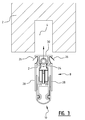
- Door 2 ( figure 1 ) comprises a recess 4 in which a door seal 6 is placed.
- Door seal 6 comprises a housing 8, also referred to as 'exterior part', in which a sealing body 10, also referred to as 'interior part', is accommodated.
- Housing 8 is in this embodiment an aluminium extrusion profile.
- the shown door seal 6 is a so-called drop seal. That is, sealing body 10 can be displaced in vertical direction as according to arrow A relative to housing 8. This movement is activated by a knob 12 which presses against door jamb 14 when the door is closed.
- Door 2 is mounted hingedly on door jamb 14, also referred to as door frame. Door 2 can therefore rotate relative to the door jamb 14.
- knob 12 The distance between knob 12 and housing 8 is adjustable.
- Knob 12 is provided for this purpose on a bush with internal screw thread screwed onto a shaft with external screw thread.
- the distance between knob 12 and the housing, and thereby the distance between knob 12 and door jamb 14, can thus be adjusted by means of screwing.
- Knob 12 can however also be adjustable in other manner relative to housing 8.
- sealing body 10 moves in the direction of the ground surface. As soon as the door is opened, knob 12 is removed from the door jamb and sealing body 10 will move upward again in the direction of housing 8 and here move clear of the ground surface. When the door is closed, the sealing body closes the opening between door 2 and the ground surface on the underside of the door. During opening of door 2 sealing body 10 no longer makes contact with the ground surface so that door 2 can be opened without frictional resistance.
- Drop seals are per se known and a door seal according to the invention can be embodied with any desired drop mechanism.
- FIG. 2 illustrates that sealing body 10 comprises a rubber profile 16 and a carrier 18.
- Profile 16 is attached to carrier 18.
- Carrier 18 is situated in housing 8.
- carrier 18 is likewise manufactured from aluminium and comprises close to its lower outer end a number of recesses 20 with outward facing openings for receiving a protrusion 22 of rubber profile 16, also referred to as 'arrowhead'.
- Arrowhead 22 is pressed into recess 20 and becomes fixedly clamped therein.
- Carrier 18 is connected movably in a manner not shown to housing 8 for vertical movement relative to the housing on the basis of activation of knob 12.
- FIGs 2 and 3 illustrate that a groove 24 in which a clip 26 is placed is provided on the upper side of housing 8. It is noted that the groove can also be provided at another position on side wall 28.
- Clip 26 is manufactured in this example from spring steel. Clip 26 is alternatively manufactured from another material, for instance a plastic.
- Figure 3 illustrates that housing 8 comprises two side walls 28 which are connected by a bridge 30 which also holds side walls 28 at a distance from each other.
- grooves 24, in each of which a clip 26 is placed are provided in both side walls 28. Clips 26 can be connected releasably to housing 8.
- groove 24 comprises an edge 30 on its underside and an edge 32 on its upper side.
- clip 26 can be pushed from an end surface of housing 8 into groove 24. Edges 30, 32 prevent clip 26 falling out of groove 24 here in the non-mounted situation.
- Housing 8 can however also be provided without edges 30, 32 or with only lower edge 30 or only with upper edge 32. It is in that case possible, if desired, to dispense with sliding clip 26 in from the end surface, and clip 26 can be placed directly at the desired position in groove 24.
- Clip 26 is substantially V-shaped. Clip 26 is in fact a bent metal plate so that a first leaf 34 and a second leaf 36 are formed ( figure 5 ). Leaves 34, 36 are connected to each other via a bent part of clip 26. Leaves 34, 36 are hereby resiliently movable relative to each other.
- Leaf 36 has a length which is slightly greater than the height of groove 24 so that leaf 36 can be clamped in groove 24.
- Leaf 36 has a curvature so that, during clamping of leaf 36 in groove 24, the free outer end of leaf 36 can move resiliently relative to the bent part connecting leaves 34, 36. Because leaf 36 can be clamped in groove 24, edges 30, 32 are not strictly speaking necessary to hold clip 26 in groove 24.
- Leaf 34 forms the resilient tongue of clip 26. In the mounted position the free outer end of the resilient tongue points in downward inclining direction.
- the outer end of tongue 34 is provided with teeth 38 which are made by making a recess in the outer end.
- Leaf 36 is provided with teeth 38 in similar manner.
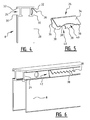
- an elongate clip 42 is provided.
- Clip 42 is provided with teeth 38 by embodying the outer end as sawtooth.
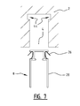
- Figure 7 shows an alternative door according to the invention in which two grooves 44 are provided in recess 4.
- the grooves 44 of recess 4 are provided on the upper side so as to correspond to the presence of clips 26 on the upper side of housing 8.
- openings 46 are cut into side walls 28 of housing 8 so that resilient tongues 48 are formed.
- the housing in this embodiment also has a groove 24, this can also be omitted.
- an elongate tongue 48 is formed by cutting into a part of side wall 28.
- resilient tongues in the embodiments of figures 8 and 9 are formed integrally with the housing. It is however also possible to attach resilient tongues in other manner to the housing. A resilient tongue of spring steel, plastic or other material is for instance manufactured, which tongue is then attached by means of screwing, glueing, welding or in other manner to side wall 28 of housing 8.
- Figures 1 and 2 show stop 50.
- Stop 50 is arranged on the short side of housing 8 situated during use on the hinge side of door 2. Stop 50 extends beyond the upper side of housing 8 and defines a contact surface facing toward the door. The stop prevents the possibility of door seal 6 sliding in the direction away from door jamb 14, i.e. in the direction toward the door handle. During opening and closing of door 2 a force is exerted in this direction on drop seal 6, which force is absorbed by stop 50. If for whatever reason door seal 2 has to be removed from door 2, door 2 is then opened and, by exerting sufficient force, door seal 2 can be pushed out of recess 4 in the direction not blocked by stop 50.
- a plastic element 52 which functions as stop is mounted in both grooves 24 on either side of housing 8.
- elements 52 are embodied in plastic.
- Elements 52 are alternatively provided from another material, for instance metal.
- Element 52 comprises a leg 54 ( figures 11A-B ) which is pushed into groove 24.
- the outer end of element 52, which is situated in use on the end surface of housing 8, comprises a stop surface 56 lying substantially at a right angle to leg 54. Stop surface 54 extends laterally relative to side wall 28 in a direction at a right angle to the side wall.
- Leg 54 of the stop 52 mountable in groove 28 is provided on its one outer end with a protrusion 58.
- protrusion 58 has a substantially cylindrical form wherein the rear side of the cylinder form is chamfered, but can also be provided according to the invention with another shape.
- housing 8 an opening 60 is provided in groove 24 for co-action with protrusion 58 of stop 52. Stop 52 is pushed from the end surface of housing 8 into groove 24, wherein stop 52 is retained in groove 24 by edge 32. By sliding stop 52 in this way in groove 24, protrusion 58 will snap into opening 60.
Abstract
Description
- The invention relates to a door seal. Such seals are used to seal an opening between the door and a ground surface. Door seals prevent draught passing through under the door, increases fire safety and/or realizes sound insulation.
- For mounting of door seals in doors it is known to make a recess on the underside of the door in which the door seal is then placed. A conventional type of door seal is mounted in the door by means of a number of screws which are screwed through an exterior part of the seal. A drawback of this conventional system is that mounting of the door seal is time-consuming.
- An object of the invention is to obviate or at least alleviate the above stated problem and to provide a door seal which can be mounted in simple manner in a recess in the underside of a door.
- This object is achieved with the door seal according to the invention, comprising:
- an elongate housing with two side walls and a connecting part which connects the side walls, wherein mounting means are provided on at least one of the side walls of the housing for the purpose of mounting the housing in a recess in the underside of the door; and
- a sealing body provided at least partially in the housing for sealing a space between the underside of the door and a ground surface,
- The door seal according to the invention can be placed easily in the recess of the door from the underside. During insertion of the door seal into the recess from the underside the inner wall of the recess will press the resilient tongue in the direction of the side wall counter to the spring force of the tongue. The resilient tongue therefore pushes against the inner wall of the recess in the door and thus clamps the housing in the recess.
- Screws are not therefore required for mounting of the door seal in the recess. The door seal according to the invention can therefore be mounted in a door in a very short time. This is a particular advantage in the large-scale production of doors, wherein because of the invention a door seal can be mounted with relatively few operations.
- The term 'door' is understood in the context of the invention to mean a door leaf, i.e. that part which can move relative to a door frame.
- The resilient tongue extends inclining downward. In other words, the resilient tongue has an angle relative to the side wall. The outer end of the tongue points here in downward direction, i.e. in the direction of the sealing body. In use the outer end of the resilient tongue will point in the direction of the ground surface.
- In a preferred embodiment the at least one side wall of the housing comprises a groove and the mounting means comprise a separate, substantially V-shaped element, wherein the resilient tongue forms a first leg of the substantially V-shaped element and a second leg of the substantially V-shaped element is placed in the groove.
- Owing to the V-shape the legs of the V-shaped element can move resiliently relative to each other. The element with resilient tongue can therefore be produced in simple manner. The V-shaped element can be coupled to the housing by placing one of the legs in the groove in the side edge of the housing. Once the door seal has been placed in a recess of a door, the resilience will hold the V-shaped element in the groove.
- In a further embodiment the groove comprises an edge for retaining the second leg of the V-shaped element behind the edge in the groove.
- For placing of the door seal according to the invention in the recess in a door, the second leg of the V-shaped element is placed behind the edge of the groove, for instance by sliding the V-shaped element into the groove from the side of the housing. This achieves that the V-shaped element is also held in the groove prior to being mounted in the door.
- In an alternative embodiment the resilient tongue and the housing are formed integrally and the resilient tongue is formed by a portion cut out of the at least one side wall.
- The tongue is for instance formed by making a portion cut out of the side wall and subsequently bending a part of the side wall so that a resilient tongue is formed.
- In a preferred embodiment according to the invention the resilient tongue has teeth on its outer end so that the tongue can engage in the door.
- The tongue can hereby bite into the inner wall of the recess so that a digging-in effect is achieved. This prevents a vertical displacement of the housing following placing in the recess. The toothed outer end will attach itself particularly well to wooden and plastic doors.
- In a further preferred embodiment a stop is mounted on at least one of the outer ends of the housing for the purpose of blocking sliding of the housing in a longitudinal direction.
- Although the resilient tongue holds the door seal in the recess, wherein vertical displacement is not possible, in some cases a horizontal displacement of the housing is not completely blocked. In such a situation the door seal can be displaced when sufficient force is exerted. Displacement in at least one longitudinal direction is blocked by providing a stop on at least one of the outer ends of the housing.
- In a further preferred embodiment both outer ends of the housing are provided with a stop. This prevents displacement in both longitudinal directions. At least one stop is in that case preferably connected releasably to the housing, for instance by means of a screw. In the case the door seal has to be removed from the door - for instance for maintenance - the releasable stop can be removed, after which the housing can be displaced in the direction of the other stop. Due to the presence of the resilient tongue some force will be necessary for this displacement. The door seal is for instance tapped out of the door using a hammer.
- In an embodiment of the door seal in which at least one side wall of the housing comprises a groove for receiving a substantially V-shaped element as described above, the stop can be embodied as a stop mountable in the groove. The stop mountable in the groove is preferably embodied as a separate part which can be snapped into the groove.
- The stop is for instance embodied as an element with at least one leg which can be pushed into the groove, and a side surface connecting to and lying substantially at a right angle to the at least one leg. The stop is fixed in the groove by sliding the stop with the at least one leg into the corresponding groove from the end surface of the housing. In the mounted position the side surface of the stop is situated on the end surface of the housing and extends beyond the side wall of the housing and/or beyond the upper side of the housing so that the side surface functions as stop surface for the purpose of preventing sliding of the housing in longitudinal direction. The leg preferably comprises a coupling means for co-action with a corresponding coupling means provided in the groove of the housing. The co-acting coupling means for instance comprise an opening and a protrusion. The protrusion is for instance embodied in the form of a stud. The leg preferably comprises a protrusion which fits into a corresponding opening or recess arranged in the groove of the housing. The leg is for instance embodied as a resilient tongue on which the protrusion is formed so that the stop can be attached to the housing by snapping the protrusion into the corresponding opening in the housing. Two of such stops are for instance provided so that a stop can be mounted in both grooves on either side of the housing.
- The stop mountable in the groove is alternatively embodied as an element with two legs so that each leg can be placed in another of the two grooves on either side of the housing.
- The groove is preferably provided with an edge for the purpose of retaining the stop mountable in the groove behind the edge.
- The invention further relates to a door comprising on its underside a recess in which a door seal as described above is provided.
- In a preferred embodiment a groove is provided in the inner wall of the recess such that the resilient tongue can move back resiliently at the position of a groove in order to hold the housing in the recess.
- In such an embodiment the resilient tongue functions as a kind of hook for holding the housing in the recess. Depending on the shape and dimension of the groove relative to the resilient tongue, the tongue will also have more or less of a clamping action.
- In a preferred embodiment the door has a hinge side for connecting the door to a door jamb via a hinge, and a stop for blocking a longitudinal movement of the housing is mounted only on the outer end of the housing located on the hinge side of the door.
- In normal use the door seal will not be able to move in longitudinal direction. The stop moreover blocks any movement of the housing here in the longitudinal direction away from the hinge side. However, if it is desired to remove the door seal from the door, for instance for maintenance, the door seal can be pushed in the longitudinal direction toward the hinge side. For this purpose the door is opened, after which the door seal is pressed with some force from the door handle side. The door seal is for instance tapped out of the recess with a hammer.
- The invention further relates to a method for manufacturing a door, comprising of providing a door with a recess on its underside and inserting a door seal as described above into the recess from the underside.
- The door and method according to the invention have the same advantages and effects as described above in respect of the door seal according to the invention.
- The recess can for instance be provided by means of milling.
- Further advantages, features and details of the invention are elucidated on the basis of preferred embodiments thereof, wherein reference is made to the accompanying drawings.
-
Figure 1 is a cut-away view of a door in which a first embodiment of a door seal according to the invention is provided; -
Figure 2 shows the door seal offigure 1 from another perspective; -
Figure 3 shows a cross-sectional side view of the door seal offigures 1 and2 ; -
Figure 4 shows the housing of the door seal offigures 1-3 in detail; -
Figure 5 shows the V-shaped clip of the door seal offigures 1-4 in detail; -
Figure 6 shows a door seal with an alternative clip; -
Figure 7 shows a door according to the invention in which a groove is provided in the recess; -
Figure 8 shows a second embodiment of a door seal according to the invention; -
Figure 9 shows a third embodiment of a door seal according to the invention; -
Figure 10 shows a fourth embodiment of a door seal according to the invention; and -
Figures 11A-B show in detail how a stop is mounted in each groove of the housing in the fourth embodiment. - Door 2 (
figure 1 ) comprises arecess 4 in which a door seal 6 is placed. Door seal 6 comprises ahousing 8, also referred to as 'exterior part', in which a sealingbody 10, also referred to as 'interior part', is accommodated.Housing 8 is in this embodiment an aluminium extrusion profile. - The shown door seal 6 is a so-called drop seal. That is, sealing
body 10 can be displaced in vertical direction as according to arrow A relative tohousing 8. This movement is activated by aknob 12 which presses against door jamb 14 when the door is closed.Door 2 is mounted hingedly ondoor jamb 14, also referred to as door frame.Door 2 can therefore rotate relative to thedoor jamb 14. - The distance between
knob 12 andhousing 8 is adjustable.Knob 12 is provided for this purpose on a bush with internal screw thread screwed onto a shaft with external screw thread. The distance betweenknob 12 and the housing, and thereby the distance betweenknob 12 and door jamb 14, can thus be adjusted by means of screwing.Knob 12 can however also be adjustable in other manner relative tohousing 8. - When
knob 12 is pressed in, sealingbody 10 moves in the direction of the ground surface. As soon as the door is opened,knob 12 is removed from the door jamb and sealingbody 10 will move upward again in the direction ofhousing 8 and here move clear of the ground surface. When the door is closed, the sealing body closes the opening betweendoor 2 and the ground surface on the underside of the door. During opening ofdoor 2 sealingbody 10 no longer makes contact with the ground surface so thatdoor 2 can be opened without frictional resistance. - Drop seals are per se known and a door seal according to the invention can be embodied with any desired drop mechanism.
-
Figure 2 illustrates that sealingbody 10 comprises arubber profile 16 and acarrier 18.Profile 16 is attached tocarrier 18.Carrier 18 is situated inhousing 8. In thisembodiment carrier 18 is likewise manufactured from aluminium and comprises close to its lower outer end a number ofrecesses 20 with outward facing openings for receiving aprotrusion 22 ofrubber profile 16, also referred to as 'arrowhead'.Arrowhead 22 is pressed intorecess 20 and becomes fixedly clamped therein.Carrier 18 is connected movably in a manner not shown tohousing 8 for vertical movement relative to the housing on the basis of activation ofknob 12. -
Figures 2 and3 illustrate that agroove 24 in which aclip 26 is placed is provided on the upper side ofhousing 8. It is noted that the groove can also be provided at another position onside wall 28.Clip 26 is manufactured in this example from spring steel.Clip 26 is alternatively manufactured from another material, for instance a plastic.Figure 3 illustrates thathousing 8 comprises twoside walls 28 which are connected by abridge 30 which also holdsside walls 28 at a distance from each other. In the shownembodiment grooves 24, in each of which aclip 26 is placed, are provided in bothside walls 28.Clips 26 can be connected releasably tohousing 8. - Mounting of
clip 26 ingroove 24 ofhousing 8 is shown in detail infigure 4 . In thisembodiment groove 24 comprises anedge 30 on its underside and anedge 32 on its upper side. In the shownembodiment clip 26 can be pushed from an end surface ofhousing 8 intogroove 24.Edges clip 26 falling out ofgroove 24 here in the non-mounted situation.Housing 8 can however also be provided withoutedges lower edge 30 or only withupper edge 32. It is in that case possible, if desired, to dispense with slidingclip 26 in from the end surface, andclip 26 can be placed directly at the desired position ingroove 24. -
Clip 26 is substantially V-shaped.Clip 26 is in fact a bent metal plate so that afirst leaf 34 and asecond leaf 36 are formed (figure 5 ).Leaves clip 26.Leaves -
Leaf 36 has a length which is slightly greater than the height ofgroove 24 so thatleaf 36 can be clamped ingroove 24.Leaf 36 has a curvature so that, during clamping ofleaf 36 ingroove 24, the free outer end ofleaf 36 can move resiliently relative to the bent part connecting leaves 34, 36. Becauseleaf 36 can be clamped ingroove 24, edges 30, 32 are not strictly speaking necessary to holdclip 26 ingroove 24. -
Leaf 34 forms the resilient tongue ofclip 26. In the mounted position the free outer end of the resilient tongue points in downward inclining direction. The outer end oftongue 34 is provided withteeth 38 which are made by making a recess in the outer end.Leaf 36 is provided withteeth 38 in similar manner. - In an alternative embodiment (
figure 6 ) anelongate clip 42 is provided.Clip 42 is provided withteeth 38 by embodying the outer end as sawtooth. -
Figure 7 shows an alternative door according to the invention in which twogrooves 44 are provided inrecess 4. In the embodiment thegrooves 44 ofrecess 4 are provided on the upper side so as to correspond to the presence ofclips 26 on the upper side ofhousing 8. - In a further embodiment openings 46 (
figure 8 ) are cut intoside walls 28 ofhousing 8 so thatresilient tongues 48 are formed. Although the housing in this embodiment also has agroove 24, this can also be omitted. - In yet another variant (
figure 9 ) anelongate tongue 48 is formed by cutting into a part ofside wall 28. - The resilient tongues in the embodiments of
figures 8 and 9 are formed integrally with the housing. It is however also possible to attach resilient tongues in other manner to the housing. A resilient tongue of spring steel, plastic or other material is for instance manufactured, which tongue is then attached by means of screwing, glueing, welding or in other manner toside wall 28 ofhousing 8. -
Figures 1 and2 show stop 50.Stop 50 is arranged on the short side ofhousing 8 situated during use on the hinge side ofdoor 2.Stop 50 extends beyond the upper side ofhousing 8 and defines a contact surface facing toward the door. The stop prevents the possibility of door seal 6 sliding in the direction away fromdoor jamb 14, i.e. in the direction toward the door handle. During opening and closing of door 2 a force is exerted in this direction on drop seal 6, which force is absorbed bystop 50. If for whateverreason door seal 2 has to be removed fromdoor 2,door 2 is then opened and, by exerting sufficient force,door seal 2 can be pushed out ofrecess 4 in the direction not blocked bystop 50. - In another exemplary embodiment (
figure 10 ) aplastic element 52 which functions as stop is mounted in bothgrooves 24 on either side ofhousing 8. In thisembodiment elements 52 are embodied in plastic.Elements 52 are alternatively provided from another material, for instance metal.Element 52 comprises a leg 54 (figures 11A-B ) which is pushed intogroove 24. The outer end ofelement 52, which is situated in use on the end surface ofhousing 8, comprises astop surface 56 lying substantially at a right angle toleg 54. Stopsurface 54 extends laterally relative toside wall 28 in a direction at a right angle to the side wall. -
Leg 54 of thestop 52 mountable ingroove 28 is provided on its one outer end with aprotrusion 58. In the shownembodiment protrusion 58 has a substantially cylindrical form wherein the rear side of the cylinder form is chamfered, but can also be provided according to the invention with another shape. Inhousing 8 anopening 60 is provided ingroove 24 for co-action withprotrusion 58 ofstop 52.Stop 52 is pushed from the end surface ofhousing 8 intogroove 24, wherein stop 52 is retained ingroove 24 byedge 32. By slidingstop 52 in this way ingroove 24,protrusion 58 will snap intoopening 60. - The present invention is by no means limited to the above described preferred embodiments thereof. The rights sought are defined by the following claims, within the scope of which many modifications can be envisaged.
Claims (12)
- Door seal, comprising:- an elongate housing with two side walls and a connecting part which connects the side walls, wherein mounting means are provided on at least one of the side walls of the housing for the purpose of mounting the housing in a recess in the underside of a door; and- a sealing body provided at least partially in the housing for sealing a space between the
underside of the door and a ground surface,
characterized in that
the mounting means comprise a resilient tongue extending from the at least one side wall in a direction inclining downward in use. - Door seal as claimed in claim 1, wherein the at least one side wall of the housing comprises a groove and the mounting means comprise a separate, substantially V-shaped element, wherein the resilient tongue forms a first leg of the substantially V-shaped element and a second leg of the substantially V-shaped element is placed in the groove.
- Door seal as claimed in claim 2, wherein the groove comprises an edge for retaining the second leg of the V-shaped element behind the edge in the groove.
- Door seal as claimed in claim 2 or 3, wherein the second leg has a curvature for the purpose of placing the second leg clampingly in the groove.
- Door seal as claimed in claim 1, wherein the resilient tongue and the housing are formed integrally and the resilient tongue is formed by a portion cut out of the at least one side wall.
- Door seal as claimed in any of the foregoing claims, wherein the resilient tongue has teeth on its outer end so that the tongue can engage in the door.
- Door seal as claimed in any of the foregoing claims, wherein a stop is mounted on at least one of the outer ends of the housing for the purpose of blocking sliding of the housing in a longitudinal direction.
- Door seal as claimed in claim 7, wherein both outer ends of the housing are provided with a stop, wherein at least one stop is connected releasably to the housing.
- Door comprising on its underside a recess in which a door seal as claimed in any of the foregoing claims is provided.
- Door as claimed in claim 9, wherein a groove is provided in the inner wall of the recess such that the resilient tongue can move back resiliently at the position of the groove in order to hold the housing in the recess.
- Door as claimed in claim 9 or 10 to the extent dependent on claim 6, wherein the door has a hinge side for connecting the door to a door jamb via a hinge, wherein a stop is mounted only on the outer end of the housing located on the hinge side of the door.
- Method for manufacturing a door, comprising of:- providing a door with a recess on its underside;- inserting a door seal as claimed in any of the claims 1-8 into the recess from the underside.
Applications Claiming Priority (1)
| Application Number | Priority Date | Filing Date | Title |
|---|---|---|---|
| NL2012920A NL2012920B1 (en) | 2014-05-30 | 2014-05-30 | Door seal, door with door seal and method for manufacturing thereof. |
Publications (2)
| Publication Number | Publication Date |
|---|---|
| EP2949855A1 true EP2949855A1 (en) | 2015-12-02 |
| EP2949855B1 EP2949855B1 (en) | 2016-11-23 |
Family
ID=51266398
Family Applications (1)
| Application Number | Title | Priority Date | Filing Date |
|---|---|---|---|
| EP15170085.3A Active EP2949855B1 (en) | 2014-05-30 | 2015-06-01 | Door seal, door with door seal and method for manufacture thereof |
Country Status (3)
| Country | Link |
|---|---|
| EP (1) | EP2949855B1 (en) |
| DK (1) | DK2949855T3 (en) |
| NL (1) | NL2012920B1 (en) |
Cited By (6)
| Publication number | Priority date | Publication date | Assignee | Title |
|---|---|---|---|---|
| DE202016101599U1 (en) | 2016-03-23 | 2016-04-18 | Athmer Ohg | Sealing profile for a door |
| CN107013145A (en) * | 2017-05-18 | 2017-08-04 | 张渝 | Sealing structure and door |
| EP3203006A1 (en) | 2016-02-02 | 2017-08-09 | Athmer oHG | Sealing profile for a door |
| CN107724907A (en) * | 2017-11-21 | 2018-02-23 | 江苏中特防火门有限公司 | One kind fire prevention resistance taste door |
| EP3543452A1 (en) | 2018-03-19 | 2019-09-25 | Planet GDZ AG | Door seal with a fixing element |
| EA034071B1 (en) * | 2017-12-11 | 2019-12-24 | Совместное Общество С Ограниченной Ответственностью "Алюминтехно" | Profile system of door structure with automatically lowering threshold and complex of coupling devices for automatic threshold unit with profile system |
Citations (3)
| Publication number | Priority date | Publication date | Assignee | Title |
|---|---|---|---|---|
| DE202007006336U1 (en) * | 2007-05-03 | 2007-08-16 | F. Athmer Ohg | Sealing housing has lateral sealing profilers extending in longitudinal direction on one or more outer sides of housing part that are suitable and designed for sealing air gap between outer sides of housing part after fitting seal in groove |
| EP2055888A2 (en) * | 2007-11-02 | 2009-05-06 | Planet GDZ AG | Door with seal and door seal for same |
| JP2009191471A (en) * | 2008-02-13 | 2009-08-27 | Pal Co Ltd | Adjusting sliding door |
-
2014
- 2014-05-30 NL NL2012920A patent/NL2012920B1/en not_active IP Right Cessation
-
2015
- 2015-06-01 DK DK15170085.3T patent/DK2949855T3/en active
- 2015-06-01 EP EP15170085.3A patent/EP2949855B1/en active Active
Patent Citations (3)
| Publication number | Priority date | Publication date | Assignee | Title |
|---|---|---|---|---|
| DE202007006336U1 (en) * | 2007-05-03 | 2007-08-16 | F. Athmer Ohg | Sealing housing has lateral sealing profilers extending in longitudinal direction on one or more outer sides of housing part that are suitable and designed for sealing air gap between outer sides of housing part after fitting seal in groove |
| EP2055888A2 (en) * | 2007-11-02 | 2009-05-06 | Planet GDZ AG | Door with seal and door seal for same |
| JP2009191471A (en) * | 2008-02-13 | 2009-08-27 | Pal Co Ltd | Adjusting sliding door |
Cited By (9)
| Publication number | Priority date | Publication date | Assignee | Title |
|---|---|---|---|---|
| EP3203006A1 (en) | 2016-02-02 | 2017-08-09 | Athmer oHG | Sealing profile for a door |
| EP3203006B1 (en) | 2016-02-02 | 2019-09-04 | Athmer oHG | Sealing profile for a door |
| DE202016101599U1 (en) | 2016-03-23 | 2016-04-18 | Athmer Ohg | Sealing profile for a door |
| CN107013145A (en) * | 2017-05-18 | 2017-08-04 | 张渝 | Sealing structure and door |
| CN107724907A (en) * | 2017-11-21 | 2018-02-23 | 江苏中特防火门有限公司 | One kind fire prevention resistance taste door |
| EA034071B1 (en) * | 2017-12-11 | 2019-12-24 | Совместное Общество С Ограниченной Ответственностью "Алюминтехно" | Profile system of door structure with automatically lowering threshold and complex of coupling devices for automatic threshold unit with profile system |
| EA034071B8 (en) * | 2017-12-11 | 2020-06-17 | Совместное Общество С Ограниченной Ответственностью "Алюминтехно" | Profile system of door structure with automatically lowering threshold and complex of coupling devices for automatic threshold unit with profile system |
| EP3543452A1 (en) | 2018-03-19 | 2019-09-25 | Planet GDZ AG | Door seal with a fixing element |
| WO2019179936A1 (en) | 2018-03-19 | 2019-09-26 | Planet Gdz Ag | Door seal having fastening element |
Also Published As
| Publication number | Publication date |
|---|---|
| DK2949855T3 (en) | 2017-02-27 |
| NL2012920B1 (en) | 2016-06-09 |
| EP2949855B1 (en) | 2016-11-23 |
Similar Documents
| Publication | Publication Date | Title |
|---|---|---|
| EP2949855B1 (en) | Door seal, door with door seal and method for manufacture thereof | |
| US10683698B2 (en) | Hinge-sided finger protection device | |
| US6827471B1 (en) | Recessed light fixture | |
| US10000957B2 (en) | Door closer assembly | |
| CN101171482A (en) | Door for a household appliance | |
| US20180119473A1 (en) | Non-Invasive Clip-On Doorstopper | |
| EP3604723B1 (en) | Combination of a profile and hinge for a window or a door with an accessory for adjusting the position between said hinge and said profile of said window or door | |
| KR102050670B1 (en) | Rail stopper for sliding windows and doors | |
| CA2840770A1 (en) | Sash cam for side load window balance system | |
| EP2890857B1 (en) | Door seal | |
| JP6456845B2 (en) | Traveling part for guiding furniture parts in the guiding direction via guide rails, and furniture fittings | |
| CN104120942A (en) | Falling prevention casement window profile and falling prevention window composed of the same | |
| AU2007237192A1 (en) | Automatic Threshold Seal | |
| FR3064544B1 (en) | GLAZING INCLUDING A PROFILE CLIP CORD FOR A CLIPABLE COVERING PART. | |
| JP6267076B2 (en) | Sliding bolt and mounting table for outdoor unit using the same | |
| GB2533684A (en) | A shower enclosure frame | |
| KR101900592B1 (en) | Handle for sliding door of built-in wardrobe | |
| EP2246515A1 (en) | Fixing assembly for door sealing | |
| EP3229324A1 (en) | Electrical cable retention | |
| EP2792830A3 (en) | Retaining element for holding a fitting element | |
| CA2888323C (en) | Door closer | |
| AU2012100488A4 (en) | Door drop seal and escutcheon plate with a dampening device | |
| DK2609608T3 (en) | ELECTRICAL CONNECTION TO A SAFETY SWITCH DEVICE | |
| BE1021732B1 (en) | COMPOSITION AND METHOD FOR FITTING AN ELECTRIC MODULE | |
| EP3523494B1 (en) | Compound profile for a window or door and a window or door assembled with such profiles |
Legal Events
| Date | Code | Title | Description |
|---|---|---|---|
| AK | Designated contracting states |
Kind code of ref document: A1 Designated state(s): AL AT BE BG CH CY CZ DE DK EE ES FI FR GB GR HR HU IE IS IT LI LT LU LV MC MK MT NL NO PL PT RO RS SE SI SK SM TR |
|
| AX | Request for extension of the european patent |
Extension state: BA ME |
|
| PUAI | Public reference made under article 153(3) epc to a published international application that has entered the european phase |
Free format text: ORIGINAL CODE: 0009012 |
|
| GRAP | Despatch of communication of intention to grant a patent |
Free format text: ORIGINAL CODE: EPIDOSNIGR1 |
|
| 17P | Request for examination filed |
Effective date: 20160526 |
|
| RBV | Designated contracting states (corrected) |
Designated state(s): AL AT BE BG CH CY CZ DE DK EE ES FI FR GB GR HR HU IE IS IT LI LT LU LV MC MK MT NL NO PL PT RO RS SE SI SK SM TR |
|
| INTG | Intention to grant announced |
Effective date: 20160630 |
|
| GRAS | Grant fee paid |
Free format text: ORIGINAL CODE: EPIDOSNIGR3 |
|
| GRAA | (expected) grant |
Free format text: ORIGINAL CODE: 0009210 |
|
| AK | Designated contracting states |
Kind code of ref document: B1 Designated state(s): AL AT BE BG CH CY CZ DE DK EE ES FI FR GB GR HR HU IE IS IT LI LT LU LV MC MK MT NL NO PL PT RO RS SE SI SK SM TR |
|
| REG | Reference to a national code |
Ref country code: GB Ref legal event code: FG4D |
|
| REG | Reference to a national code |
Ref country code: CH Ref legal event code: EP |
|
| REG | Reference to a national code |
Ref country code: IE Ref legal event code: FG4D |
|
| REG | Reference to a national code |
Ref country code: AT Ref legal event code: REF Ref document number: 848096 Country of ref document: AT Kind code of ref document: T Effective date: 20161215 |
|
| REG | Reference to a national code |
Ref country code: DE Ref legal event code: R096 Ref document number: 602015000789 Country of ref document: DE |
|
| REG | Reference to a national code |
Ref country code: DE Ref legal event code: R096 Ref document number: 602015000789 Country of ref document: DE |
|
| REG | Reference to a national code |
Ref country code: DE Ref legal event code: R082 Ref document number: 602015000789 Country of ref document: DE Representative=s name: ARNOLD & SIEDSMA, DE |
|
| REG | Reference to a national code |
Ref country code: NL Ref legal event code: FP |
|
| REG | Reference to a national code |
Ref country code: DK Ref legal event code: T3 Effective date: 20170221 |
|
| PG25 | Lapsed in a contracting state [announced via postgrant information from national office to epo] |
Ref country code: LV Free format text: LAPSE BECAUSE OF FAILURE TO SUBMIT A TRANSLATION OF THE DESCRIPTION OR TO PAY THE FEE WITHIN THE PRESCRIBED TIME-LIMIT Effective date: 20161123 |
|
| REG | Reference to a national code |
Ref country code: LT Ref legal event code: MG4D |
|
| REG | Reference to a national code |
Ref country code: AT Ref legal event code: MK05 Ref document number: 848096 Country of ref document: AT Kind code of ref document: T Effective date: 20161123 |
|
| PG25 | Lapsed in a contracting state [announced via postgrant information from national office to epo] |
Ref country code: GR Free format text: LAPSE BECAUSE OF FAILURE TO SUBMIT A TRANSLATION OF THE DESCRIPTION OR TO PAY THE FEE WITHIN THE PRESCRIBED TIME-LIMIT Effective date: 20170224 Ref country code: NO Free format text: LAPSE BECAUSE OF FAILURE TO SUBMIT A TRANSLATION OF THE DESCRIPTION OR TO PAY THE FEE WITHIN THE PRESCRIBED TIME-LIMIT Effective date: 20170223 Ref country code: LT Free format text: LAPSE BECAUSE OF FAILURE TO SUBMIT A TRANSLATION OF THE DESCRIPTION OR TO PAY THE FEE WITHIN THE PRESCRIBED TIME-LIMIT Effective date: 20161123 Ref country code: SE Free format text: LAPSE BECAUSE OF FAILURE TO SUBMIT A TRANSLATION OF THE DESCRIPTION OR TO PAY THE FEE WITHIN THE PRESCRIBED TIME-LIMIT Effective date: 20161123 |
|
| PG25 | Lapsed in a contracting state [announced via postgrant information from national office to epo] |
Ref country code: AT Free format text: LAPSE BECAUSE OF FAILURE TO SUBMIT A TRANSLATION OF THE DESCRIPTION OR TO PAY THE FEE WITHIN THE PRESCRIBED TIME-LIMIT Effective date: 20161123 Ref country code: RS Free format text: LAPSE BECAUSE OF FAILURE TO SUBMIT A TRANSLATION OF THE DESCRIPTION OR TO PAY THE FEE WITHIN THE PRESCRIBED TIME-LIMIT Effective date: 20161123 Ref country code: HR Free format text: LAPSE BECAUSE OF FAILURE TO SUBMIT A TRANSLATION OF THE DESCRIPTION OR TO PAY THE FEE WITHIN THE PRESCRIBED TIME-LIMIT Effective date: 20161123 Ref country code: PL Free format text: LAPSE BECAUSE OF FAILURE TO SUBMIT A TRANSLATION OF THE DESCRIPTION OR TO PAY THE FEE WITHIN THE PRESCRIBED TIME-LIMIT Effective date: 20161123 Ref country code: FI Free format text: LAPSE BECAUSE OF FAILURE TO SUBMIT A TRANSLATION OF THE DESCRIPTION OR TO PAY THE FEE WITHIN THE PRESCRIBED TIME-LIMIT Effective date: 20161123 Ref country code: ES Free format text: LAPSE BECAUSE OF FAILURE TO SUBMIT A TRANSLATION OF THE DESCRIPTION OR TO PAY THE FEE WITHIN THE PRESCRIBED TIME-LIMIT Effective date: 20161123 Ref country code: PT Free format text: LAPSE BECAUSE OF FAILURE TO SUBMIT A TRANSLATION OF THE DESCRIPTION OR TO PAY THE FEE WITHIN THE PRESCRIBED TIME-LIMIT Effective date: 20170323 |
|
| REG | Reference to a national code |
Ref country code: FR Ref legal event code: PLFP Year of fee payment: 3 |
|
| PG25 | Lapsed in a contracting state [announced via postgrant information from national office to epo] |
Ref country code: EE Free format text: LAPSE BECAUSE OF FAILURE TO SUBMIT A TRANSLATION OF THE DESCRIPTION OR TO PAY THE FEE WITHIN THE PRESCRIBED TIME-LIMIT Effective date: 20161123 Ref country code: CZ Free format text: LAPSE BECAUSE OF FAILURE TO SUBMIT A TRANSLATION OF THE DESCRIPTION OR TO PAY THE FEE WITHIN THE PRESCRIBED TIME-LIMIT Effective date: 20161123 Ref country code: SK Free format text: LAPSE BECAUSE OF FAILURE TO SUBMIT A TRANSLATION OF THE DESCRIPTION OR TO PAY THE FEE WITHIN THE PRESCRIBED TIME-LIMIT Effective date: 20161123 Ref country code: RO Free format text: LAPSE BECAUSE OF FAILURE TO SUBMIT A TRANSLATION OF THE DESCRIPTION OR TO PAY THE FEE WITHIN THE PRESCRIBED TIME-LIMIT Effective date: 20161123 |
|
| REG | Reference to a national code |
Ref country code: DE Ref legal event code: R097 Ref document number: 602015000789 Country of ref document: DE |
|
| PG25 | Lapsed in a contracting state [announced via postgrant information from national office to epo] |
Ref country code: SM Free format text: LAPSE BECAUSE OF FAILURE TO SUBMIT A TRANSLATION OF THE DESCRIPTION OR TO PAY THE FEE WITHIN THE PRESCRIBED TIME-LIMIT Effective date: 20161123 Ref country code: IT Free format text: LAPSE BECAUSE OF FAILURE TO SUBMIT A TRANSLATION OF THE DESCRIPTION OR TO PAY THE FEE WITHIN THE PRESCRIBED TIME-LIMIT Effective date: 20161123 Ref country code: BG Free format text: LAPSE BECAUSE OF FAILURE TO SUBMIT A TRANSLATION OF THE DESCRIPTION OR TO PAY THE FEE WITHIN THE PRESCRIBED TIME-LIMIT Effective date: 20170223 |
|
| PLBE | No opposition filed within time limit |
Free format text: ORIGINAL CODE: 0009261 |
|
| STAA | Information on the status of an ep patent application or granted ep patent |
Free format text: STATUS: NO OPPOSITION FILED WITHIN TIME LIMIT |
|
| 26N | No opposition filed |
Effective date: 20170824 |
|
| PG25 | Lapsed in a contracting state [announced via postgrant information from national office to epo] |
Ref country code: SI Free format text: LAPSE BECAUSE OF FAILURE TO SUBMIT A TRANSLATION OF THE DESCRIPTION OR TO PAY THE FEE WITHIN THE PRESCRIBED TIME-LIMIT Effective date: 20161123 |
|
| PG25 | Lapsed in a contracting state [announced via postgrant information from national office to epo] |
Ref country code: MC Free format text: LAPSE BECAUSE OF FAILURE TO SUBMIT A TRANSLATION OF THE DESCRIPTION OR TO PAY THE FEE WITHIN THE PRESCRIBED TIME-LIMIT Effective date: 20161123 |
|
| REG | Reference to a national code |
Ref country code: IE Ref legal event code: MM4A |
|
| PG25 | Lapsed in a contracting state [announced via postgrant information from national office to epo] |
Ref country code: LU Free format text: LAPSE BECAUSE OF NON-PAYMENT OF DUE FEES Effective date: 20170601 Ref country code: IE Free format text: LAPSE BECAUSE OF NON-PAYMENT OF DUE FEES Effective date: 20170601 |
|
| REG | Reference to a national code |
Ref country code: FR Ref legal event code: PLFP Year of fee payment: 4 |
|
| PG25 | Lapsed in a contracting state [announced via postgrant information from national office to epo] |
Ref country code: MT Free format text: LAPSE BECAUSE OF NON-PAYMENT OF DUE FEES Effective date: 20170601 |
|
| REG | Reference to a national code |
Ref country code: CH Ref legal event code: PL |
|
| PG25 | Lapsed in a contracting state [announced via postgrant information from national office to epo] |
Ref country code: CH Free format text: LAPSE BECAUSE OF NON-PAYMENT OF DUE FEES Effective date: 20180630 Ref country code: LI Free format text: LAPSE BECAUSE OF NON-PAYMENT OF DUE FEES Effective date: 20180630 |
|
| PG25 | Lapsed in a contracting state [announced via postgrant information from national office to epo] |
Ref country code: HU Free format text: LAPSE BECAUSE OF FAILURE TO SUBMIT A TRANSLATION OF THE DESCRIPTION OR TO PAY THE FEE WITHIN THE PRESCRIBED TIME-LIMIT; INVALID AB INITIO Effective date: 20150601 |
|
| PG25 | Lapsed in a contracting state [announced via postgrant information from national office to epo] |
Ref country code: CY Free format text: LAPSE BECAUSE OF FAILURE TO SUBMIT A TRANSLATION OF THE DESCRIPTION OR TO PAY THE FEE WITHIN THE PRESCRIBED TIME-LIMIT Effective date: 20161123 |
|
| PG25 | Lapsed in a contracting state [announced via postgrant information from national office to epo] |
Ref country code: MK Free format text: LAPSE BECAUSE OF FAILURE TO SUBMIT A TRANSLATION OF THE DESCRIPTION OR TO PAY THE FEE WITHIN THE PRESCRIBED TIME-LIMIT Effective date: 20161123 |
|
| PG25 | Lapsed in a contracting state [announced via postgrant information from national office to epo] |
Ref country code: TR Free format text: LAPSE BECAUSE OF FAILURE TO SUBMIT A TRANSLATION OF THE DESCRIPTION OR TO PAY THE FEE WITHIN THE PRESCRIBED TIME-LIMIT Effective date: 20161123 |
|
| PG25 | Lapsed in a contracting state [announced via postgrant information from national office to epo] |
Ref country code: AL Free format text: LAPSE BECAUSE OF FAILURE TO SUBMIT A TRANSLATION OF THE DESCRIPTION OR TO PAY THE FEE WITHIN THE PRESCRIBED TIME-LIMIT Effective date: 20161123 Ref country code: IS Free format text: LAPSE BECAUSE OF FAILURE TO SUBMIT A TRANSLATION OF THE DESCRIPTION OR TO PAY THE FEE WITHIN THE PRESCRIBED TIME-LIMIT Effective date: 20170323 |
|
| P01 | Opt-out of the competence of the unified patent court (upc) registered |
Effective date: 20230507 |
|
| PGFP | Annual fee paid to national office [announced via postgrant information from national office to epo] |
Ref country code: NL Payment date: 20230626 Year of fee payment: 9 Ref country code: FR Payment date: 20230626 Year of fee payment: 9 Ref country code: DK Payment date: 20230628 Year of fee payment: 9 Ref country code: DE Payment date: 20230626 Year of fee payment: 9 |
|
| PGFP | Annual fee paid to national office [announced via postgrant information from national office to epo] |
Ref country code: BE Payment date: 20230627 Year of fee payment: 9 |
|
| PGFP | Annual fee paid to national office [announced via postgrant information from national office to epo] |
Ref country code: GB Payment date: 20230627 Year of fee payment: 9 |