EP2949847B1 - Adjustable control lever - Google Patents
Adjustable control lever Download PDFInfo
- Publication number
- EP2949847B1 EP2949847B1 EP15167918.0A EP15167918A EP2949847B1 EP 2949847 B1 EP2949847 B1 EP 2949847B1 EP 15167918 A EP15167918 A EP 15167918A EP 2949847 B1 EP2949847 B1 EP 2949847B1
- Authority
- EP
- European Patent Office
- Prior art keywords
- actuating arm
- adjustment
- end side
- contour
- adjusting
- Prior art date
- Legal status (The legal status is an assumption and is not a legal conclusion. Google has not performed a legal analysis and makes no representation as to the accuracy of the status listed.)
- Active
Links
- 238000005553 drilling Methods 0.000 description 5
- 238000005452 bending Methods 0.000 description 2
- 238000010276 construction Methods 0.000 description 1
- 238000013016 damping Methods 0.000 description 1
- 230000003247 decreasing effect Effects 0.000 description 1
- 238000006073 displacement reaction Methods 0.000 description 1
- 230000000694 effects Effects 0.000 description 1
- 238000004146 energy storage Methods 0.000 description 1
- 238000004080 punching Methods 0.000 description 1
Images


Classifications
-
- E—FIXED CONSTRUCTIONS
- E05—LOCKS; KEYS; WINDOW OR DOOR FITTINGS; SAFES
- E05D—HINGES OR SUSPENSION DEVICES FOR DOORS, WINDOWS OR WINGS
- E05D15/00—Suspension arrangements for wings
- E05D15/26—Suspension arrangements for wings for folding wings
- E05D15/262—Suspension arrangements for wings for folding wings folding vertically
-
- E—FIXED CONSTRUCTIONS
- E05—LOCKS; KEYS; WINDOW OR DOOR FITTINGS; SAFES
- E05F—DEVICES FOR MOVING WINGS INTO OPEN OR CLOSED POSITION; CHECKS FOR WINGS; WING FITTINGS NOT OTHERWISE PROVIDED FOR, CONCERNED WITH THE FUNCTIONING OF THE WING
- E05F1/00—Closers or openers for wings, not otherwise provided for in this subclass
- E05F1/08—Closers or openers for wings, not otherwise provided for in this subclass spring-actuated, e.g. for horizontally sliding wings
- E05F1/10—Closers or openers for wings, not otherwise provided for in this subclass spring-actuated, e.g. for horizontally sliding wings for swinging wings, e.g. counterbalance
- E05F1/1041—Closers or openers for wings, not otherwise provided for in this subclass spring-actuated, e.g. for horizontally sliding wings for swinging wings, e.g. counterbalance with a coil spring perpendicular to the pivot axis
- E05F1/105—Closers or openers for wings, not otherwise provided for in this subclass spring-actuated, e.g. for horizontally sliding wings for swinging wings, e.g. counterbalance with a coil spring perpendicular to the pivot axis with a compression spring
- E05F1/1058—Closers or openers for wings, not otherwise provided for in this subclass spring-actuated, e.g. for horizontally sliding wings for swinging wings, e.g. counterbalance with a coil spring perpendicular to the pivot axis with a compression spring for counterbalancing
-
- E—FIXED CONSTRUCTIONS
- E05—LOCKS; KEYS; WINDOW OR DOOR FITTINGS; SAFES
- E05Y—INDEXING SCHEME RELATING TO HINGES OR OTHER SUSPENSION DEVICES FOR DOORS, WINDOWS OR WINGS AND DEVICES FOR MOVING WINGS INTO OPEN OR CLOSED POSITION, CHECKS FOR WINGS AND WING FITTINGS NOT OTHERWISE PROVIDED FOR, CONCERNED WITH THE FUNCTIONING OF THE WING
- E05Y2600/00—Mounting or coupling arrangements for elements provided for in this subclass
- E05Y2600/10—Adjustable or movable
- E05Y2600/30—Adjustable or movable characterised by the type of motion
- E05Y2600/33—Stepwise motion
-
- E—FIXED CONSTRUCTIONS
- E05—LOCKS; KEYS; WINDOW OR DOOR FITTINGS; SAFES
- E05Y—INDEXING SCHEME RELATING TO HINGES OR OTHER SUSPENSION DEVICES FOR DOORS, WINDOWS OR WINGS AND DEVICES FOR MOVING WINGS INTO OPEN OR CLOSED POSITION, CHECKS FOR WINGS AND WING FITTINGS NOT OTHERWISE PROVIDED FOR, CONCERNED WITH THE FUNCTIONING OF THE WING
- E05Y2800/00—Details, accessories and auxiliary operations not otherwise provided for
- E05Y2800/37—Length, width adjustment
-
- E—FIXED CONSTRUCTIONS
- E05—LOCKS; KEYS; WINDOW OR DOOR FITTINGS; SAFES
- E05Y—INDEXING SCHEME RELATING TO HINGES OR OTHER SUSPENSION DEVICES FOR DOORS, WINDOWS OR WINGS AND DEVICES FOR MOVING WINGS INTO OPEN OR CLOSED POSITION, CHECKS FOR WINGS AND WING FITTINGS NOT OTHERWISE PROVIDED FOR, CONCERNED WITH THE FUNCTIONING OF THE WING
- E05Y2900/00—Application of doors, windows, wings or fittings thereof
- E05Y2900/20—Application of doors, windows, wings or fittings thereof for furnitures, e.g. cabinets
Description
Die Erfindung betrifft eine Vorrichtung zum Bewegen einer an einem Möbelkorpus bewegbar aufgenommenen Faltklappe gemäß dem Oberbegriff des Anspruchs 1 sowie ein Möbel.The invention relates to a device for moving a folding flap which is movably received on a furniture body according to the preamble of
Auf dem Gebiet des Möbelbaus sind Vorrichtungen zum Bewegen einer Faltklappe, die an einem Möbelkorpus bewegbar aufgenommen ist, in verschiedensten Ausführungen bekannt, z.B. aus der
Außerdem ist für eine Faltklappe häufig ein zweiter Stellarm vorgesehen, der im montierten Zustand mit einem zweiten Klappenelement verbunden ist, um zum Beispiel unkontrollierte, insbesondere schwingende Bewegungen des zweiten Klappenelements zu vermeiden. Des Weiteren ist bekannt zumindest einen der Stellarme aus mehreren Stellarmabschnitten zusammenzusetzen, wobei zum Beispiel zwei Stellarmabschnitte durch eine Verstelleinrichtung miteinander verbunden sein können.In addition, a second actuating arm is often provided for a folding flap, which in the assembled state is connected to a second flap element in order to avoid, for example, uncontrolled, in particular oscillating, movements of the second flap element. Furthermore, it is known to assemble at least one of the actuating arms from a plurality of actuating arm sections, wherein, for example, two actuating arm sections can be connected to one another by an adjusting device.
Der Erfindung liegt die Aufgabe zu Grunde eine Vorrichtung zum Bewegen einer Faltklappe bereitzustellen, deren Einstellbarkeit verbessert ist.The invention is based on the object of providing a device for moving a folding flap, the adjustability of which is improved.
Die Aufgabe wird mit einer Vorrichtung mit den Merkmalen des Anspruchs 1 gelöst.The object is achieved with a device with the features of
Bevorzugte und vorteilhafte Ausführungen der Erfindung sind in den Unteransprüchen angegeben.Preferred and advantageous embodiments of the invention are specified in the subclaims.
Die Erfindung geht von einer Vorrichtung zum Bewegen einer an einem Möbelkorpus bewegbar aufgenommenen Faltklappe aus wenigstens zwei gelenkig verbundenen Klappenelementen mit einer Krafteinheit aus, die über einen im montierten Zustand an einem ersten Klappenelement angeordneten Stellarm das Öffnen der Faltklappe durch Krafteinwirkung zumindest unterstützt. Die Vorrichtung ist mit einem zweiten Stellarm, der im montierten Zustand mit einem zweiten Klappenelement verbunden ist, ausgestattet. Dabei umfasst wenigstens einer der beiden Stellarme zwei Stellarmabschnitte, die über eine Verstelleinrichtung miteinander verbunden sind.The invention is based on a device for moving a folding flap movably received on a furniture carcass consisting of at least two articulated flap elements with a force unit which at least supports the opening of the folding flap through the action of force via an actuating arm arranged on a first flap element in the assembled state. The device is equipped with a second actuating arm which, in the assembled state, is connected to a second flap element. In this case, at least one of the two actuating arms comprises two actuating arm sections which are connected to one another via an adjusting device.
Der Kern der Erfindung besteht darin, dass an einem ersten Stellarmabschnitt ein Verstellelement mit einer spiralförmigen Verstellkontur drehbar gelagert ist, wobei an einem zweiten Stellarmabschnitt eine Eingreifstruktur ausgebildet ist, die zum Eingreifen in die Verstellkontur ausgebildet ist.The essence of the invention is that an adjusting element with a spiral-shaped adjusting contour is rotatably mounted on a first actuating arm section, an engagement structure being formed on a second actuating arm section which is designed to engage the adjusting contour.
Die Verstellkontur kann beispielsweise derart spiralförmig ausgebildet sein, dass einem Drehsinn entsprechend aufeinanderfolgende Eingreifpositionen an der Verstellkontur einen zunehmenden Abstand von einer vorgegebenen Drehachse aufweisen, wobei sich der Abstand beispielsweise proportional zu einem im Drehsinn zunehmenden Verdrehwinkel vergrößern kann. Hierbei ist ein Bezugs- bzw. Mittelpunkt der spiralförmigen Verstellkontur, insbesondere ein Ausgangspunkt der Spiralform vorzugsweise in der Drehachse des Verstellelements angeordnet.The adjustment contour can, for example, be spiral-shaped in such a way that successive engagement positions on the adjustment contour corresponding to a direction of rotation have an increasing distance from a predetermined axis of rotation, the distance being able to increase proportionally, for example, to an increasing angle of rotation in the direction of rotation. Here, a reference or center point of the spiral adjustment contour, in particular a starting point of the spiral shape, is preferably arranged in the axis of rotation of the adjustment element.
Die Eingreifstruktur kann derart eingreifen, dass ein Abschnitt der Eingreifstruktur an einem Abschnitt der Verstellkontur punkt- und/oder linienförmig anliegt. Außerdem kann die Eingreifstruktur derart ausgebildet sein, dass sie an der spiralförmigen Verstellstruktur flächig z.B. über einen Winkelabschnitt um eine Drehachse des Verstellelements erstreckt anliegt. Vorzugsweise sind dabei seitlich begrenzende Flächenbereiche der Verstellkontur für ein Abstützen der Eingreifstruktur vorgesehen. Die Verstelleinrichtung lässt sich dadurch relativ einfach selbsthemmend ausbilden, wobei eine Belastung am Stellarm ein unbeabsichtigtes Verdrehen des Verstellelements sowohl bei einer Einstellungsänderung am Stellarm als auch nach einer Fixierung einer Einstellung verhindern kann.The engagement structure can intervene in such a way that a section of the engagement structure rests point-like and / or linearly against a section of the adjustment contour. In addition, the engagement structure can be designed in such a way that it is flat on the spiral adjustment structure, for example via a Angular section extends around an axis of rotation of the adjusting element rests. Laterally delimiting surface areas of the adjustment contour are preferably provided for supporting the engagement structure. As a result, the adjusting device can be designed to be self-locking relatively easily, with a load on the actuating arm being able to prevent unintentional rotation of the adjusting element both when a setting is changed on the actuating arm and after a setting has been fixed.
Das Verstellelement und insbesondere eine Drehachse des Verstellelements ist vorzugsweise ortsfest bezüglich des ersten Stellarmabschnitts gelagert. Die Eingreifstruktur ist am zweiten Stellarmabschnitt vorzugsweise ortsfest ausgebildet.The adjusting element and in particular an axis of rotation of the adjusting element is preferably mounted in a stationary manner with respect to the first actuating arm section. The engagement structure is preferably designed to be stationary on the second actuating arm section.
Die Verstellkontur ist an einer Stirnseite des Verstellelements vorzugsweise zwischen zwei parallelen Ebenen ausgebildet, die senkrecht zu einer Verstelldrehachse gelegen sind. Dadurch ist eine Verschiebung der Eingreifstruktur entlang - z.B. parallel - der Drehachse des Verstellelements vermeidbar, wenn das Verstellelement bezüglich der Eingreifstruktur gedreht wird.The adjustment contour is preferably formed on an end face of the adjustment element between two parallel planes which are perpendicular to an adjustment axis of rotation. As a result, a displacement of the engagement structure along - e.g. parallel - the axis of rotation of the adjustment element can be avoided when the adjustment element is rotated with respect to the engagement structure.
Des Weiteren kann die spiralförmige Verstellkontur in Form einer wendelförmigen Rampe ausgebildet sein, die sich mit z.B. abnehmendem Abstand von der Drehachse des Verstellelements axial zunehmend erstreckt und um die Drehachse umlaufend ausgebildet ist. Dadurch lässt sich z.B. eine vergleichsweise große Kontakt- bzw. Stützfläche zwischen der Eingreifstruktur und dem Verstellelement bereitstellen.Furthermore, the spiral adjustment contour can be designed in the form of a helical ramp which, for example, extends axially with decreasing distance from the axis of rotation of the adjustment element and is designed to run around the axis of rotation. In this way, for example, a comparatively large contact or support surface can be provided between the engagement structure and the adjustment element.
Eine äußere Ebene kann dabei eine Reibfläche bereitstellen, an die eine Druckfläche für eine Fixierung einer Winkelstellung des Verstellelements anpressbar ist. Die Druckfläche kann z.B. eine Seitenfläche eines der Stellarmabschnitte sein, die der äußeren Ebene des Verstellelements zugewandt anbringbar ist. Beispielsweise kann durch ein Anziehen einer Schraube, mit der sich die beiden Stellarmabschnitte verbinden lassen, die Seitenfläche des Stellarmabschnitts abschnittsweise an die äußere Ebene angedrückt sein. Außerdem kann die Druckfläche ein Oberflächenbereich der Eingreifstruktur sein.An outer plane can provide a friction surface against which a pressure surface for fixing an angular position of the adjusting element can be pressed. The pressure surface can, for example, be a side surface of one of the actuating arm sections, which can be attached facing the outer plane of the adjusting element. For example, by tightening a screw with which the two actuating arm sections can be connected, the Side surface of the actuating arm section be pressed against the outer plane in sections. In addition, the pressure surface can be a surface area of the engagement structure.
Um eine platzsparende, stabile Form des Verstellelements zu erreichen, kann das Verstellelement eine vorzugsweise kreisförmige Scheibe umfassen, an der die spiralförmige Verstellkontur an einer Stirnseite stegförmig hervorstehend ausgebildet ist. Dadurch lässt sich das Verstellelement vergleichsweise einfach mit einer Verstellkontur ausbilden, die über mehr als eine Drehung verstellbar ist.In order to achieve a space-saving, stable shape of the adjustment element, the adjustment element can comprise a preferably circular disk on which the spiral adjustment contour is designed to protrude in the form of a web on one end face. As a result, the adjustment element can be designed comparatively easily with an adjustment contour that can be adjusted via more than one rotation.
Vorzugsweise ist die Stirnseite mit der stegförmigen Verstellkontur eine kreisscheibenförmige, ebene Fläche, die nur im Bereich der Verstellkontur von einer ebenen Ausbildung abweicht. Dadurch lässt sich die Verstelleinrichtung vergleichsweise platzsparend ausbilden. Der Mittelpunkt der Spirale ist vorzugsweise konzentrisch zur kreisscheibenförmigen Stirnfläche ausgebildet. Dadurch ist das Verstellelement aus verschiedenen Ausgangspositionen zumindest näherungsweise mit einem gleichen Drehmoment verstellbar. Die kreisscheibenförmige Stirnfläche kann z.B. eine Stirnfläche einer zylindrischen Scheibe sein, deren Mantelfläche vorteilhaft für eine drehbare Lagerung nutzbar ist. Dadurch ist eine zusätzliche Struktur für eine drehbare Lagerung wie z.B. ein Lagerzapfen verzichtbar.The end face with the web-shaped adjusting contour is preferably a circular disk-shaped, flat surface which deviates from a flat design only in the area of the adjusting contour. As a result, the adjustment device can be designed to be comparatively space-saving. The center of the spiral is preferably designed concentrically to the circular disk-shaped end face. As a result, the adjusting element can be adjusted at least approximately with the same torque from different starting positions. The circular disk-shaped end face can, for example, be an end face of a cylindrical disk, the outer surface of which can advantageously be used for a rotatable mounting. This means that an additional structure for a rotatable bearing such as a bearing pin can be dispensed with.
Je nach Stellung des Verstellelements kann die Eingreifstruktur am zweiten Stellarmabschnitt mit einem Verstellkonturabschnitt unterschiedlicher Neigung zusammenwirken. Dementsprechend ist die Eingreifstruktur am zweiten Stellarmabschnitt vorzugsweise ein Zapfen beziehungsweise nockenförmiger bzw. zapfenförmiger Vorsprung mit einem kreis- oder ellipsenförmigen Querschnitt. Dadurch lässt sich bei einem Verstellen vorteilhaft ein Verklemmen der Eingreifstruktur an der spiralförmigen Verstellkontur verringern.Depending on the position of the adjusting element, the engagement structure on the second actuating arm section can interact with an adjusting contour section of different inclination. Accordingly, the engagement structure on the second actuating arm section is preferably a pin or a cam-shaped or pin-shaped projection with a circular or elliptical cross section. As a result, jamming of the engagement structure on the spiral-shaped adjustment contour can advantageously be reduced during an adjustment.
Des Weiteren kann das Verstellelement eine Scheibe umfassen, an der die spiralförmige Verstellkontur an einer Stirnseite als nutförmige Vertiefung ausgebildet ist. Hierfür kann die Eingreifstruktur ebenfalls als Zapfen beziehungsweise noppenförmiger Vorsprung mit kreis- oder ellipsenförmigen Querschnitt ausgebildet sein. Das Verstellelement lässt sich auf diese Weise vergleichsweise stabil und mit einem vergleichsweise geringen Bewegungsspiel für die Eingreifstruktur ausbilden. Des Weiteren kann an der Stirnseite mit der Verstellkontur vorteilhaft eine größere Kontaktfläche zum Fixieren des Verstellelementes bereitgestellt werden.Furthermore, the adjusting element can comprise a disk, on which the spiral adjustment contour is designed as a groove-shaped recess on one end face. For this purpose, the engagement structure can also be designed as a pin or knob-shaped projection with a circular or elliptical cross-section. In this way, the adjusting element can be designed to be comparatively stable and with comparatively little play for the engagement structure. Furthermore, a larger contact surface for fixing the adjusting element can advantageously be provided on the front side with the adjusting contour.
Eine bevorzugte Ausführung der Erfindung besteht darin, dass an einer Stirnseite des Verstellelements, die zur Stirnseite der Verstellkontur entgegengesetzt angeordnet ist, ein Lagerzapfen insbesondere zentral hervorstehend ausgebildet ist. Damit kann das Verstellelement vergleichsweise stabil gelagert sein. Wenn ein Lagerzapfen nur an der Stirnseite ausgebildet ist, die am Verstellelement der Seite mit der Verstellkontur entgegengesetzt liegt, lässt sich vorteilhaft vermeiden, dass die spiralförmige Verstellkontur zugunsten eines Lagerzapfen auf der gleichen Stirnseite verkürzt ist und dadurch ein Verstellbereich des Verstellelements verringert ist. Der Lagerzapfen kann dabei in einer Länge hervorstehend ausgebildet sein, dass der Lagerzapfen in eine Öffnung beziehungsweise Ausnehmung eines Stellarmabschnitts hineinreicht und insbesondere hindurchreicht.A preferred embodiment of the invention consists in that a bearing journal is formed in particular protruding centrally on an end face of the adjusting element which is arranged opposite to the end face of the adjusting contour. The adjusting element can thus be mounted in a comparatively stable manner. If a bearing journal is only formed on the end face that is opposite the side with the adjustment contour on the adjustment element, it can advantageously be avoided that the spiral adjustment contour is shortened in favor of a bearing journal on the same end face and thereby an adjustment range of the adjustment element is reduced. The bearing pin can be designed to protrude to a length such that the bearing pin extends into an opening or recess of an actuating arm section and, in particular, extends through it.
Der Lagerzapfen hat vorzugsweise einen kleineren Durchmesser als die Scheibe, damit ein überstehender Randabschnitt der Stirnseite mit dem Lagerzapfen als Druckfläche zum Beispiel zur Fixierung einer Winkelstellung des Verstellelements zur Verfügung steht. Dabei lässt sich außerdem eine Verstellbarkeit des Verstellelements erleichtern.The bearing pin preferably has a smaller diameter than the disk so that a protruding edge section of the end face with the bearing pin is available as a pressure surface, for example for fixing an angular position of the adjusting element. Adjustability of the adjusting element can also be made easier in this case.
Des Weiteren ist es bevorzugt, dass an einer Stirnseite des Verstellelements, die zur Stirnseite der Verstellkontur entgegengesetzt gelegen ist, und insbesondere am Lagerzapfen ein Eingriff für ein Verstellwerkzeug ausgebildet ist.Furthermore, it is preferred that an engagement for an adjusting tool is formed on an end face of the adjusting element which is opposite to the end face of the adjusting contour, and in particular on the bearing journal.
Verstelleinrichtung weist dadurch einen vorteilhaft einfachen Aufbau auf.Adjusting device thus has an advantageously simple structure.
Des Weiteren kann an der Stirnseite des Verstellelements, an der die Verstellkontur ausgebildet ist, ein Lagerzapfen zentral aus der Stirnseite hervorstehen. Insbesondere wenn an der Stirnseite der Verstellkontur und an einer am Verstellelement entgegengesetzten Stirnseite jeweils ein Lagerzapfen hervorstehend ausgebildet ist, kann das Verstellelement damit zum Beispiel symmetrisch drehbar gelagert sein, um Verschleiß erhöhende Krafteinwirkungen zu reduzieren.Furthermore, a bearing pin can protrude centrally from the end face on the end face of the adjustment element on which the adjustment contour is formed. In particular if a bearing journal is formed protruding on the end face of the adjustment contour and on an end face opposite the adjustment element, the adjustment element can thus be mounted so that it can rotate symmetrically, for example, in order to reduce wear-increasing forces.
Eine Winkelstellung des Verstellelements ist vorzugsweise mit einer Schraubverbindung der beiden Stellarmabschnitte fixierbar, die vorzugsweise neben dem Verstellelement angeordnet ist. Vorzugsweise ist die Schraubverbindung dazu vorgesehen, einen Flächenabschnitt eines Elements des Stellarms derart mit dem Verstellelement in reibschlüssigen Kontakt zu bringen, dass das Verstellelement nicht mehr verdrehbar ist. Hierfür können auch mehrere Schraubverbindungen vorhanden sein.An angular position of the adjusting element can preferably be fixed with a screw connection of the two adjusting arm sections, which is preferably arranged next to the adjusting element. The screw connection is preferably provided to bring a surface section of an element of the actuating arm into frictional contact with the adjusting element in such a way that the adjusting element can no longer be rotated. Several screw connections can also be provided for this purpose.
Um eine vergleichsweise einfache stufenlose Verstellung durch die Verstelleinrichtung zu ermöglichen, ist an einem der Stellarmabschnitte eine insbesondere gewindelose Durchstecköffnung der Schraubverbindung als Langloch ausgebildet, das insbesondere in Längsrichtung des zweiten Stellarms erstreckt ist. Dabei ist das Langloch bezüglich einer Verstellrichtung in einer solchen Länge ausgebildet, dass eine Schraube für eine Fixierung der Verstelleinrichtung im Langloch verschiebbar positioniert ist, d.h. nicht im Langloch anschlägt, wenn das Verstellelement in einem Drehsinn entlang der Verstellkontur überdreht wird, d.h. wenn das Verstellelement weiter gedreht wird, als sich die Verstellkontur in Richtung des Drehsinns erstreckt. Dadurch sind Beschädigungen an der Verstellkontur und an der Eingreifstruktur durch Überdrehen des Verstellelements vermeidbar.In order to enable a comparatively simple stepless adjustment by the adjusting device, an in particular threadless push-through opening of the screw connection is formed as an elongated hole on one of the actuating arm sections, which in particular extends in the longitudinal direction of the second actuating arm. The elongated hole is designed with a length such that a screw for fixing the adjusting device in the elongated hole is displaceably positioned, ie does not strike the elongated hole when the adjusting element is overturned in one direction of rotation along the adjusting contour, ie when the adjusting element continues is rotated when the adjustment contour extends in the direction of the direction of rotation. As a result, damage to the adjustment contour and to the engagement structure by over-turning the adjustment element can be avoided.
Damit die Vorrichtung vorteilhaft für verschiedene Ausführungen von Faltklappen einsetzbar ist, ist an einem der Stellarmabschnitte eine Reihe von mehreren Bohrungen für zumindest eine Schraubverbindung des Stellarmabschnitts ausgebildet, die insbesondere mit einem an wenigstens eine Fixierschraube angepassten Innengewinde versehen sind.So that the device can advantageously be used for different designs of folding flaps, a number of several bores for at least one screw connection of the actuating arm section are formed on one of the actuating arm sections, which are in particular provided with an internal thread adapted to at least one fixing screw.
Die benachbarte Bohrungen zum Einschrauben der Fixierschraube sind in einer Längsrichtung des Stellarms vorzugsweise in einem Abstand z.B. eines maximalen Verstellwegs des Verstellelements und insbesondere einem doppelten maximalen Verstellweg angeordnet. Dabei ermöglicht die Anordnung der Bohrungen zum Einschrauben der Fixierschraube eine Grobeinstellung des Stellarms, die mit der Verstelleinrichtung durch Drehen des Verstellelements für eine Feineinstellung abstimmbar ist.The adjacent bores for screwing in the fixing screw are preferably arranged in a longitudinal direction of the actuating arm at a distance, for example a maximum adjustment path of the adjusting element and in particular a double maximum adjustment path. The arrangement of the bores for screwing in the fixing screw enables a coarse adjustment of the actuating arm, which can be coordinated with the adjustment device by turning the adjustment element for a fine adjustment.
Die Verstelleinrichtung kann einen Lagerkörper umfassen, der das Verstellelement senkrecht zur Verstelldrehachse umgibt, wobei der Lagerkörper zur Anordnung zwischen den Stellarmabschnitten vorgesehen ist. Dabei kann der Lagerkörper vorteilhaft zur Fixierung oder auch zur Grobpositionierung des Verstellelements beitragen. Des Weiteren lassen sich dadurch die Verstelleinrichtung und der Stellarm stabiler ausbilden, weil nicht nur das Verstellelement Stützstellen zwischen den beiden Stellarmabschnitten bereitstellt.The adjusting device can comprise a bearing body which surrounds the adjusting element perpendicular to the adjusting axis of rotation, the bearing body being provided for arrangement between the actuating arm sections. The bearing body can advantageously contribute to the fixing or also to the rough positioning of the adjusting element. Furthermore, the adjustment device and the actuating arm can be designed to be more stable because not only the adjusting element provides support points between the two actuating arm sections.
Das Verstellelement kann im Lagerkörper derart gelagert sein, dass das Verstellelement in Richtung der Verstelldrehachse an wenigstens einer Seite des Lagerkörpers über dessen Oberfläche hinausragt. Dadurch lässt sich das Verstellelement, insgesamt mit dessen Stirnseiten vorteilhaft zwischen dem Lagerkörper und zum Beispiel einem der Stellarmabschnitte zur Fixierung festklemmen.The adjusting element can be mounted in the bearing body in such a way that the adjusting element protrudes in the direction of the adjusting axis of rotation on at least one side of the bearing body beyond its surface. As a result, the adjusting element, overall with its end faces, can advantageously be clamped between the bearing body and, for example, one of the actuating arm sections for fixing purposes.
Außerdem ist es bevorzugt, dass die Stellarmabschnitte mit der Verstelleinrichtung entlang einer geraden Längsachse des Stellarms zueinander verstellbar sind. Durch die einfache und überschaubare Wirkung einer Längenänderung ist dabei ein Einstellen eines Stellarms erleichtert.In addition, it is preferred that the adjusting arm sections can be adjusted with respect to one another with the adjusting device along a straight longitudinal axis of the adjusting arm. Due to the simple and manageable effect of a change in length, there is a Adjusting an actuator arm made easier.
Die Erfindung wird nachfolgend an mehreren Ausführungsbeispielen mit Hilfe der Zeichnungen beschrieben.The invention is described below using several exemplary embodiments with the aid of the drawings.
Es zeigen:
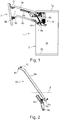
Figur 1- eine seitliche Schnittansicht eines Möbelfachs mit einer erfindungsgemäßen Vorrichtung,
Figur 2- eine schematische perspektivische Explosionsansicht eines Stellhebels,
- Figur 3
- eine vergrößerte Ansicht eines Ausschnitts aus der
Figur 2 Figur 4- eine vergrößerter Ausschnitt aus der
Figur 5 , - Figur 5
- eine schematische perspektivische Explosionsansicht eines Stellarms eines zweiten Ausführungsbeispiels der Erfindung,
- Figur 6
- eine schematische, perspektivische Ansicht des Stellarms im zusammengesetzten Zustand.
- Figure 1
- a side sectional view of a furniture compartment with a device according to the invention,
- Figure 2
- a schematic perspective exploded view of an adjusting lever,
- Figure 3
- an enlarged view of a portion of the
Figure 2 , - Figure 4
- an enlarged section from the
Figure 5 , - Figure 5
- a schematic perspective exploded view of an actuating arm of a second embodiment of the invention,
- Figure 6
- a schematic, perspective view of the actuating arm in the assembled state.
In der
Die Stellvorrichtung 4 umfasst ein Montageelement 4a sowie einen ersten Stellarm 6a und einen zweiten Stellarm 6b, wobei die beiden Stellarme 6a und 6b schwenkbar am Montageelement 4a gelagert sind. Am Montagelement 4a ist des Weiteren ein Energiespeicher 4b angebracht, der über eine Hebelmechanik Kräfte auf z.B. den Stellarm 6a übertragen kann.The adjusting
Das Montageelement 4a ist an einer Seitenwand 2c des Möbelfachs 2 nahe einer Möbeldecke 2a befestigt und zum Beispiel angeschraubt.The mounting
Der erste Stellarm 6a ist mit dem oberen Klappenelement 3a fest verbunden, wobei der Stellarm 6a vorzugsweise dazu ausgelegt ist, Gewichtskräfte der beiden Möbelplatten 3a und 3b sowie das Scharnier 5 auf das Montageelement 4a zu übertragen.The
Der zweite Stellarm 6b ist mit dem zweiten Klappenelement 3b über ein Drehlager 7 beweglich verbunden. Der Stellarm 6b ist dabei vorgesehen, das zweite Klappenelement 3b beim Schließen in eine vorgegebene Schließposition zu führen und dort zu halten. Eine weitere Aufgabe des Stellarms 6b besteht darin, beim Öffnen der Möbelklappe 3 ein unkontrolliertes Schwingen des Klappenelements 3b am Klappenelement 3a zu vermeiden, insbesondere wenn das zweite Klappenelement 3b frei schwenkbar, d.h. ohne eine Einwirkung eines dämpfenden Drehmoments durch das Scharnier 5 mit dem oberen Klappenelement 3a verbunden ist. Der Stellarm 6b ist hierbei derart ausgebildet und insbesondere verstellbar, dass das zweite Klappenelement 3b eine vorgegebene Schließposition wiederholbar erreichen kann und eine Bewegungsführung durch den Stellarm 6b sich gegebenenfalls nachjustieren lässt.The
Der Stellarm 6b des ersten Ausführungsbeispiels einer erfindungsgemäßen Vorrichtung ist in den
Am ersten Stellarmabschnitt 8b ist eine Aussparung 11 ausgebildet, in die sich ein Endabschnitt des zweiten Stellarmabschnittes 8a, an dem eine Bohrung 9a ausgebildet ist, einlegen lässt. Die Aussparung 11 ist dabei derart an einen Querschnitt des Stellarmabschnitts 8a angepasst, dass sich der Stellarmabschnitt 8a vorzugsweise bündig mit einem Oberflächenbereich 12 des Stellarmabschnitts 8b einlegen lässt und in der Aussparung 11 parallel zu einer Längsachse L des Stellarmabschnitts 8b verschiebbar ist. Dadurch ist der Stellarmabschnitt 8a zumindest teilweise formschlüssig mit dem Stellarmabschnitt 8b verbunden, um Stellkräfte vom Montageelement 4a auf das Klappenelement 3b zu übertragen.A
Zur Befestigung des zweiten Stellarmabschnitts 8a am ersten Stellarmabschnitt 8b ist eine Schraube 13 vorgesehen, die sich von einer in der Ansicht der
Das Verstellelement 16 mit der spiralförmigen Verstellkontur 17 ist in einer im Wesentlichen kreisförmigen Ausnehmung 18 gelagert, an der die Aussparung 11 am Stellarmabschnitt 8b zusätzlich vertieft ist. Von einem Mittelpunkt der Ausnehmung 18 ausgehend ist in Richtung der Längsachse die Ausnehmung 18 durch eine Ausbuchtung 18a erweitert, um den Vorsprüngen 14 bei einer Verstellung des Verstellelements 16 einen zusätzlichen Bewegungsraum bereitzustellen.The
Wenn die durch die längliche Bohrung 9b hindurchgesteckte Schraube 13 an der Bohrung 9a noch nicht festgezogen ist, liegt der Stellarmabschnitt 9a lose bzw. locker an dem Verstellelement 16 an. Dabei kann die stegförmige Verstellkontur 17 in den Bereich der Aussparung 11 in einer Höhe hineinragen, die sich durch ein Festziehen der Schraube 13 vorzugsweise derart reduzieren lässt, dass der Endabschnitt des Stellarmabschnitts 8a in der Aussparung 11 eingebettet liegt. Bei festgezogener Schraube 13 kann ein dem Verstellelement 16 zugewandter Oberflächenabschnitt des Stellarmabschnitts 8a, an dem die nockenförmigen Vorsprünge 14 ausgebildet sind, das Verstellelement 16 an der Verstellkontur 17 durch Reibungskraftschluss festsetzen. Dabei liegen die nockenförmigen Vorsprünge 14 seitlich an der stegförmigen Verstellkontur 17 an, wodurch sie in Richtung der Längsachse an der stegförmigen Verstellkontur 17 abgestützt sein können.If the
Bei gelöster Schraube 13 lässt sich das Verstellelements 16 innerhalb der Ausnehmung 18 um den Mittelpunkt 16a des Verstellelements 16 verdrehen und dadurch ein Bereich der stegförmigen Verstellkontur 17 für eine Abstützung der nockenförmigen Vorsprünge 14 einstellen. Dadurch ist stufenlos eine von mehreren verschiedenen Positionen des Stellarmabschnitts 8a gegenüber dem Stellarmabschnitt 8b entlang der Längsachse L wählbar, die sich durch ein Festziehen der Schraube 13 fixieren lässt.When the
Für ein Verstellen des Verstellelements 16 ist an der Ausnehmung 18 eine kreisförmig durchbrochene Öffnung 19 ausgebildet, durch die das Verstellelement 16 in einem zusammengesetzten Zustand des Stellarms 6b von außen erreichbar ist. Dabei kann an einer in den
Die Verbindung der Stellarmabschnitte 8a und 8b in der Aussparung 11 des ersten Stellarmabschnitts 8b bietet den Vorteil, dass dadurch Biegekräfte am Stellarm 6b vom Stellelement 16 und der Schraube 13 ferngehalten sind. Dadurch lässt sich vorteilhaft vermeiden, dass das Stellelement 16 und die Schraube 13 durch z.B. Scherkräfte beschädigt werden.The connection of the
Ein Stellarm 6b eines zweiten Ausführungsbeispiels einer erfindungsgemäßen Stellvorrichtung 4 ist in den
Der Stellarm 6b weist einen ersten Stellarmabschnitt 8b und einen separaten zweiten Stellarmabschnitt 8a auf. Am Stellarmabschnitt 8b ist eine Aussparung 11 ausgebildet, die an einen z.B. rechteckigen Querschnitt eines geraden Endabschnitts des Stellarmabschnitts 8a angepasst ist, um den Stellarmabschnitt 8a zumindest teilweise formschlüssig mit dem Stellarmabschnitt 8b zu verbinden. Durch die formschlüssig an den Stellarmabschnitt 8a angepasste Aussparung 11 sind Biegebelastung an der Verbindung der Stellarmabschnitte 8a und 8b entlang einer Längsachse L übertragbar, wodurch eine erhöhte Stabilität des Stellarms 6b erreichbar ist.The
Am Stellarmabschnitt 8b sind im Bereich der Aussparung 11 eine Vielzahl von Bohrungen 9b ausgebildet, wobei vorzugsweise jede Bohrung mit einem Innengewinde versehen ist, in das eine Fixierschraube 13 einschraubbar ist. Die Fixierschraube 16 weist eine solche Länge auf, dass sich die Fixierschraube 13 in einer der Bohrungen 9b am Stellarmabschnitt 8b festziehen lässt, wenn die Fixierschraube 13 durch eine Bohrung 9c einer Klemmplatte 20 sowie durch eine Bohrung 9a am geraden Endabschnitt des Stellarmabschnitts 8a durchgesteckt ist.A plurality of
Die Klemmplatte 20 ist des Weiteren für eine Aufnahme des Verstellelements 16 ausgebildet, das mit einem zylindrischen Vorsprung 16b durch eine Öffnung 19 der Klemmplatte 20 hindurch reicht. Der zylindrische Vorsprung 16b und die Öffnung 19 für eine ortsfeste, drehbare Lagerung des Verstellelements 16 zwischen der Klemmplatte 20 und dem Stellarmabschnitt 8a ausgebildet, wenn die Klemmplatte 20 mit der Fixierschraube 13 am Stellarmabschnitt 8b locker verbunden ist. Durch ein Festziehen der Fixierschraube 13 ist das Verstellelement 16 zwischen der Klemmplatte 20 und dem Stellarmabschnitt 8a eingespannt und reibschlüssig gegen Veränderungen einer Stellung, insbesondere einer Drehstellung festgesetzt. An einer dem Stellarmabschnitt 8a zugewandten Seite weist das Stellelement 16 eine spiralförmige Verstellkontur 17 auf, die beispielsweise wie die in
Entlang einer Längsachse L' sind am Stellarmabschnitt 8a nockenförmige Vorspünge 14 als Eingreifstruktur neben der Bohrung 9a ausgebildet. Die nockenförmigen Vorsprünge sind zum Eingriff in die Verstellkontur 17 des Verstellelements 16 vorgesehen, wenn der Stellarm 6b wie z.B. in
- 11
- Möbelfurniture
- 22
- StaufachStorage compartment
- 2a2a
- DeckenplatteCeiling plate
- 2b2 B
- Bodenfloor
- 2c2c
- StaufachwandStorage compartment wall
- 33
- MöbelklappeFurniture flap
- 3a3a
- KlappenelementFlap element
- 3b3b
- KlappenelementFlap element
- 44th
- StellvorrichtungAdjusting device
- 4a4a
- MontageelementMounting element
- 4b4b
- EnergiespeicherEnergy storage
- 55
- Scharnierhinge
- 6a6a
- StellarmControl arm
- 6b6b
- StellarmControl arm
- 77th
- DrehlagerPivot bearing
- 8a8a
- StellarmabschnittActuator arm section
- 8b8b
- StellarmabschnittActuator arm section
- 8c8c
- Bohrungdrilling
- 8d8d
- Bohrungdrilling
- 9a9a
- Bohrungdrilling
- 9b9b
- Bohrungdrilling
- 9c9c
- Bohrungdrilling
- 1010
- DrehlagerzapfenPivot pin
- 1111
- AussparungRecess
- 1212th
- SeitenflächeSide face
- 1313th
- Schraubescrew
- 1414th
- Vorsprunghead Start
- 1515th
- SeitenflächeSide face
- 1616
- VerstellelementAdjustment element
- 16a16a
- MittelpunktFocus
- 16b16b
- Vorsprunghead Start
- 1717th
- VerstellkonturAdjustment contour
- 1818th
- AusnehmungRecess
- 18a18a
- Ausbuchtungbulge
- 1919th
- Öffnungopening
- 2020th
- KlemmplatteClamping plate
Claims (14)
- Apparatus (4) for moving a folding flap (3) which is movably received on a furniture carcass (2) and which is composed of at least two flap elements (3a, 3b) that are connected in an articulated manner, having a force unit (4b) which by means of a first actuating arm (6a) of the apparatus, said first actuating arm being arranged on a first flap element (3a) in the assembled state, at least assists the opening of the folding flap by action of force, and having a second actuating arm (6b) which is connected to a second flap element (3b) in the assembled state, wherein at least one of the two actuating arms (6a, 6b) comprises two actuating arm portions (8a, 8b) which are connected to one another by means of an adjustment device (14, 16), characterized in that an adjustment element (16) with a spiral-shaped adjustment contour (17) is rotatably mounted on the first actuating arm portion (8b), and in that an engagement structure (14) which is configured for engagement into the adjustment contour (17) is configured on the second actuating arm portion (8a).
- Apparatus (4) according to Claim 1, characterized in that the adjustment contour (17) is configured on an end side of the adjustment element (16) between two parallel planes which are situated perpendicularly with respect to an axis of rotary adjustment.
- Apparatus (4) according to either of the preceding claims, characterized in that the adjustment element (16) comprises a disc on which the spiral-shaped adjustment contour (17) is configured so as to protrude on an end side in a web-like manner.
- Apparatus (4) according to Claim 2 or 3, characterized in that the adjustment element (16) comprises a disc on which the spiral-shaped adjustment contour (17) is configured in the form of a groove-like recess on an end side.
- Apparatus (4) according to one of Claims 2-4, characterized in that a bearing pin (16b) is configured so as to protrude centrally on an end side of the adjustment element (16), said end side being arranged oppositely to the end side of the adjustment contour (17) .
- Apparatus (4) according to one of Claims 2-5, characterized in that an engagement means for an adjustment tool is configured on an end side of the adjustment element (16), said end side being situated oppositely to the end side of the adjustment contour (17), and in particular on the bearing pin (16b).
- Apparatus (4) according to one of Claims 2-6, characterized in that, on that end side of the adjustment element (16) on which the adjustment contour (17) is configured, a bearing pin protrudes centrally from the end side.
- Apparatus (4) according to one of the preceding claims, characterized in that an angular position of the adjustment element (16) can be fixed by way of a screw connection (9a, 9b, 9c, 13) of the two actuating arm portions (8a, 8b).
- Apparatus (4) according to one of the preceding claims, characterized in that a threadless push-through opening (9a, 9b, 9c) of the screw connection (9a, 9b, 9c, 13) is configured in the form of a slot on one of the actuating arm portions (8a, 8b), said slot extending in particular in a longitudinal direction of the corresponding actuating arm (6a, 6b).
- Apparatus (4) according to one of the preceding claims, characterized in that a row of several bores (9b) for at least one screw connection (9a, 9b, 9c, 13) of the actuating arm portions (8a, 8b) is configured on one of the actuating arm portions (8a, 8b), said bores being provided in particular with an internal thread adapted to the fixing screw (13).
- Apparatus (4) according to one of the preceding claims, characterized in that the adjustment device (14, 16) comprises a bearing body (8b, 20) which surrounds the adjustment element (16) perpendicularly with respect to the axis of rotary adjustment, wherein the bearing body is provided for arrangement on the actuating arm portions (8a, 8b).
- Apparatus (4) according to Claim 11, characterized in that the adjustment element (16) is mounted in the bearing body (8b, 20) in such a way that the adjustment element (16) projects, in the direction of the axis of rotary adjustment, beyond the surface of the bearing body (20) on at least one side thereof.
- Apparatus (4) according to one of the preceding claims, characterized in that the actuating arm portions (8a, 8b) can be adjusted relative to one another along a straight longitudinal axis L of the actuating arm (6a, 6b) by way of the adjustment device (14, 16).
- Item of furniture (1) having an apparatus (4) according to one of the preceding claims.
Applications Claiming Priority (1)
| Application Number | Priority Date | Filing Date | Title |
|---|---|---|---|
| DE202014102477.8U DE202014102477U1 (en) | 2014-05-27 | 2014-05-27 | Adjustable control lever |
Publications (2)
| Publication Number | Publication Date |
|---|---|
| EP2949847A1 EP2949847A1 (en) | 2015-12-02 |
| EP2949847B1 true EP2949847B1 (en) | 2021-09-01 |
Family
ID=53177262
Family Applications (1)
| Application Number | Title | Priority Date | Filing Date |
|---|---|---|---|
| EP15167918.0A Active EP2949847B1 (en) | 2014-05-27 | 2015-05-18 | Adjustable control lever |
Country Status (2)
| Country | Link |
|---|---|
| EP (1) | EP2949847B1 (en) |
| DE (1) | DE202014102477U1 (en) |
Families Citing this family (2)
| Publication number | Priority date | Publication date | Assignee | Title |
|---|---|---|---|---|
| EP3625417B1 (en) * | 2017-05-15 | 2021-08-25 | Samet Kalip Ve Madeni Esya San. Ve Tic. A.S. | Length-adjustable control arm |
| PL3625415T3 (en) | 2017-05-15 | 2023-12-27 | Samet Kalip Ve Madeni Esya San. Ve Tic. A.S. | Flap bearing with an adjustment aid |
Family Cites Families (6)
| Publication number | Priority date | Publication date | Assignee | Title |
|---|---|---|---|---|
| DE9109033U1 (en) * | 1991-07-22 | 1991-09-12 | Heinrich Brinkmann Gmbh & Co Kg, 4520 Melle, De | |
| AT1214U1 (en) * | 1995-12-18 | 1996-12-27 | Blum Gmbh Julius | HINGE |
| AT407277B (en) * | 1998-08-11 | 2001-02-26 | Blum Gmbh Julius | HINGE |
| AT414257B (en) * | 2004-10-12 | 2006-10-15 | Blum Gmbh Julius | HOLDING AND ADJUSTMENT DEVICE FOR MOVING FURNITURE PARTS |
| AT501396B1 (en) * | 2004-10-28 | 2007-10-15 | Blum Gmbh Julius | FALTTÜRENSCHARNIER |
| ITMI20050181A1 (en) * | 2005-02-09 | 2006-08-10 | Effegi Brevetti Srl | OPENING-CLOSING DEVICE OF A FURNITURE DOOR OF A FURNITURE |
-
2014
- 2014-05-27 DE DE202014102477.8U patent/DE202014102477U1/en not_active Expired - Lifetime
-
2015
- 2015-05-18 EP EP15167918.0A patent/EP2949847B1/en active Active
Also Published As
| Publication number | Publication date |
|---|---|
| DE202014102477U1 (en) | 2015-08-28 |
| EP2949847A1 (en) | 2015-12-02 |
Similar Documents
| Publication | Publication Date | Title |
|---|---|---|
| EP2527576B1 (en) | Moving device for pivotable partition elements and furniture | |
| EP3177839B1 (en) | Bolt for bracing parts lying on one another | |
| EP2880334B1 (en) | Ring nut | |
| EP0774324A2 (en) | Pliers with two plierarms | |
| DE102009025890A1 (en) | Device for attaching a front panel to a side frame of a movable furniture part of a piece of furniture, drawer and furniture | |
| AT6962U1 (en) | HINGE | |
| EP3088645B1 (en) | Connection device for a sliding door | |
| WO2012116777A2 (en) | Fastening element for a solar module frame | |
| EP2265784B1 (en) | Adjusting device for furniture | |
| EP4013969B1 (en) | Tightening element | |
| EP2949847B1 (en) | Adjustable control lever | |
| EP3359826B1 (en) | Furniture fitting | |
| EP2217409B1 (en) | Hand power tool with a handle | |
| EP0708219A1 (en) | Fitting or the like, preferably hinge part, with fastening device | |
| DE10006587C2 (en) | Adjustable hinge | |
| DE4436199C1 (en) | Radius actuator e.g for machinery safety switches | |
| EP2949845B1 (en) | Adjustable flap bearing | |
| DE4342683C2 (en) | Safety device for struts | |
| EP1777363B1 (en) | Stop device for a door of a housing | |
| EP3808997B1 (en) | Dowel device | |
| DE10216478B4 (en) | Articulated arm awning | |
| EP1022502A1 (en) | Quick-fastening nut and a pipe clamp with such a nut | |
| EP2740872B1 (en) | Corner bearing for concealed assembly | |
| EP3291395B1 (en) | Installation box for ceiling selection | |
| EP1640541A2 (en) | Device for stopping a swingable apparatus, in particular a door or window |
Legal Events
| Date | Code | Title | Description |
|---|---|---|---|
| AK | Designated contracting states |
Kind code of ref document: A1 Designated state(s): AL AT BE BG CH CY CZ DE DK EE ES FI FR GB GR HR HU IE IS IT LI LT LU LV MC MK MT NL NO PL PT RO RS SE SI SK SM TR |
|
| AX | Request for extension of the european patent |
Extension state: BA ME |
|
| PUAI | Public reference made under article 153(3) epc to a published international application that has entered the european phase |
Free format text: ORIGINAL CODE: 0009012 |
|
| 17P | Request for examination filed |
Effective date: 20160602 |
|
| RBV | Designated contracting states (corrected) |
Designated state(s): AL AT BE BG CH CY CZ DE DK EE ES FI FR GB GR HR HU IE IS IT LI LT LU LV MC MK MT NL NO PL PT RO RS SE SI SK SM TR |
|
| STAA | Information on the status of an ep patent application or granted ep patent |
Free format text: STATUS: EXAMINATION IS IN PROGRESS |
|
| 17Q | First examination report despatched |
Effective date: 20170906 |
|
| RAP1 | Party data changed (applicant data changed or rights of an application transferred) |
Owner name: GRASS GMBH |
|
| STAA | Information on the status of an ep patent application or granted ep patent |
Free format text: STATUS: EXAMINATION IS IN PROGRESS |
|
| RIC1 | Information provided on ipc code assigned before grant |
Ipc: E05F 1/10 20060101ALI20210216BHEP Ipc: E05D 15/26 20060101AFI20210216BHEP |
|
| GRAP | Despatch of communication of intention to grant a patent |
Free format text: ORIGINAL CODE: EPIDOSNIGR1 |
|
| STAA | Information on the status of an ep patent application or granted ep patent |
Free format text: STATUS: GRANT OF PATENT IS INTENDED |
|
| INTG | Intention to grant announced |
Effective date: 20210413 |
|
| GRAS | Grant fee paid |
Free format text: ORIGINAL CODE: EPIDOSNIGR3 |
|
| GRAA | (expected) grant |
Free format text: ORIGINAL CODE: 0009210 |
|
| STAA | Information on the status of an ep patent application or granted ep patent |
Free format text: STATUS: THE PATENT HAS BEEN GRANTED |
|
| AK | Designated contracting states |
Kind code of ref document: B1 Designated state(s): AL AT BE BG CH CY CZ DE DK EE ES FI FR GB GR HR HU IE IS IT LI LT LU LV MC MK MT NL NO PL PT RO RS SE SI SK SM TR |
|
| REG | Reference to a national code |
Ref country code: GB Ref legal event code: FG4D Free format text: NOT ENGLISH |
|
| REG | Reference to a national code |
Ref country code: CH Ref legal event code: EP Ref country code: AT Ref legal event code: REF Ref document number: 1426428 Country of ref document: AT Kind code of ref document: T Effective date: 20210915 |
|
| REG | Reference to a national code |
Ref country code: DE Ref legal event code: R096 Ref document number: 502015015127 Country of ref document: DE |
|
| REG | Reference to a national code |
Ref country code: IE Ref legal event code: FG4D Free format text: LANGUAGE OF EP DOCUMENT: GERMAN |
|
| REG | Reference to a national code |
Ref country code: LT Ref legal event code: MG9D |
|
| REG | Reference to a national code |
Ref country code: NL Ref legal event code: MP Effective date: 20210901 |
|
| PG25 | Lapsed in a contracting state [announced via postgrant information from national office to epo] |
Ref country code: HR Free format text: LAPSE BECAUSE OF FAILURE TO SUBMIT A TRANSLATION OF THE DESCRIPTION OR TO PAY THE FEE WITHIN THE PRESCRIBED TIME-LIMIT Effective date: 20210901 Ref country code: SE Free format text: LAPSE BECAUSE OF FAILURE TO SUBMIT A TRANSLATION OF THE DESCRIPTION OR TO PAY THE FEE WITHIN THE PRESCRIBED TIME-LIMIT Effective date: 20210901 Ref country code: RS Free format text: LAPSE BECAUSE OF FAILURE TO SUBMIT A TRANSLATION OF THE DESCRIPTION OR TO PAY THE FEE WITHIN THE PRESCRIBED TIME-LIMIT Effective date: 20210901 Ref country code: ES Free format text: LAPSE BECAUSE OF FAILURE TO SUBMIT A TRANSLATION OF THE DESCRIPTION OR TO PAY THE FEE WITHIN THE PRESCRIBED TIME-LIMIT Effective date: 20210901 Ref country code: FI Free format text: LAPSE BECAUSE OF FAILURE TO SUBMIT A TRANSLATION OF THE DESCRIPTION OR TO PAY THE FEE WITHIN THE PRESCRIBED TIME-LIMIT Effective date: 20210901 Ref country code: NO Free format text: LAPSE BECAUSE OF FAILURE TO SUBMIT A TRANSLATION OF THE DESCRIPTION OR TO PAY THE FEE WITHIN THE PRESCRIBED TIME-LIMIT Effective date: 20211201 Ref country code: BG Free format text: LAPSE BECAUSE OF FAILURE TO SUBMIT A TRANSLATION OF THE DESCRIPTION OR TO PAY THE FEE WITHIN THE PRESCRIBED TIME-LIMIT Effective date: 20211201 Ref country code: LT Free format text: LAPSE BECAUSE OF FAILURE TO SUBMIT A TRANSLATION OF THE DESCRIPTION OR TO PAY THE FEE WITHIN THE PRESCRIBED TIME-LIMIT Effective date: 20210901 |
|
| PG25 | Lapsed in a contracting state [announced via postgrant information from national office to epo] |
Ref country code: PL Free format text: LAPSE BECAUSE OF FAILURE TO SUBMIT A TRANSLATION OF THE DESCRIPTION OR TO PAY THE FEE WITHIN THE PRESCRIBED TIME-LIMIT Effective date: 20210901 Ref country code: LV Free format text: LAPSE BECAUSE OF FAILURE TO SUBMIT A TRANSLATION OF THE DESCRIPTION OR TO PAY THE FEE WITHIN THE PRESCRIBED TIME-LIMIT Effective date: 20210901 Ref country code: GR Free format text: LAPSE BECAUSE OF FAILURE TO SUBMIT A TRANSLATION OF THE DESCRIPTION OR TO PAY THE FEE WITHIN THE PRESCRIBED TIME-LIMIT Effective date: 20211202 |
|
| PG25 | Lapsed in a contracting state [announced via postgrant information from national office to epo] |
Ref country code: IS Free format text: LAPSE BECAUSE OF FAILURE TO SUBMIT A TRANSLATION OF THE DESCRIPTION OR TO PAY THE FEE WITHIN THE PRESCRIBED TIME-LIMIT Effective date: 20220101 Ref country code: SM Free format text: LAPSE BECAUSE OF FAILURE TO SUBMIT A TRANSLATION OF THE DESCRIPTION OR TO PAY THE FEE WITHIN THE PRESCRIBED TIME-LIMIT Effective date: 20210901 Ref country code: SK Free format text: LAPSE BECAUSE OF FAILURE TO SUBMIT A TRANSLATION OF THE DESCRIPTION OR TO PAY THE FEE WITHIN THE PRESCRIBED TIME-LIMIT Effective date: 20210901 Ref country code: RO Free format text: LAPSE BECAUSE OF FAILURE TO SUBMIT A TRANSLATION OF THE DESCRIPTION OR TO PAY THE FEE WITHIN THE PRESCRIBED TIME-LIMIT Effective date: 20210901 Ref country code: PT Free format text: LAPSE BECAUSE OF FAILURE TO SUBMIT A TRANSLATION OF THE DESCRIPTION OR TO PAY THE FEE WITHIN THE PRESCRIBED TIME-LIMIT Effective date: 20220103 Ref country code: NL Free format text: LAPSE BECAUSE OF FAILURE TO SUBMIT A TRANSLATION OF THE DESCRIPTION OR TO PAY THE FEE WITHIN THE PRESCRIBED TIME-LIMIT Effective date: 20210901 Ref country code: EE Free format text: LAPSE BECAUSE OF FAILURE TO SUBMIT A TRANSLATION OF THE DESCRIPTION OR TO PAY THE FEE WITHIN THE PRESCRIBED TIME-LIMIT Effective date: 20210901 Ref country code: CZ Free format text: LAPSE BECAUSE OF FAILURE TO SUBMIT A TRANSLATION OF THE DESCRIPTION OR TO PAY THE FEE WITHIN THE PRESCRIBED TIME-LIMIT Effective date: 20210901 Ref country code: AL Free format text: LAPSE BECAUSE OF FAILURE TO SUBMIT A TRANSLATION OF THE DESCRIPTION OR TO PAY THE FEE WITHIN THE PRESCRIBED TIME-LIMIT Effective date: 20210901 |
|
| REG | Reference to a national code |
Ref country code: DE Ref legal event code: R097 Ref document number: 502015015127 Country of ref document: DE |
|
| PLBE | No opposition filed within time limit |
Free format text: ORIGINAL CODE: 0009261 |
|
| STAA | Information on the status of an ep patent application or granted ep patent |
Free format text: STATUS: NO OPPOSITION FILED WITHIN TIME LIMIT |
|
| PG25 | Lapsed in a contracting state [announced via postgrant information from national office to epo] |
Ref country code: DK Free format text: LAPSE BECAUSE OF FAILURE TO SUBMIT A TRANSLATION OF THE DESCRIPTION OR TO PAY THE FEE WITHIN THE PRESCRIBED TIME-LIMIT Effective date: 20210901 |
|
| 26N | No opposition filed |
Effective date: 20220602 |
|
| PG25 | Lapsed in a contracting state [announced via postgrant information from national office to epo] |
Ref country code: SI Free format text: LAPSE BECAUSE OF FAILURE TO SUBMIT A TRANSLATION OF THE DESCRIPTION OR TO PAY THE FEE WITHIN THE PRESCRIBED TIME-LIMIT Effective date: 20210901 |
|
| REG | Reference to a national code |
Ref country code: CH Ref legal event code: PL |
|
| REG | Reference to a national code |
Ref country code: BE Ref legal event code: MM Effective date: 20220531 |
|
| GBPC | Gb: european patent ceased through non-payment of renewal fee |
Effective date: 20220518 |
|
| PG25 | Lapsed in a contracting state [announced via postgrant information from national office to epo] |
Ref country code: MC Free format text: LAPSE BECAUSE OF FAILURE TO SUBMIT A TRANSLATION OF THE DESCRIPTION OR TO PAY THE FEE WITHIN THE PRESCRIBED TIME-LIMIT Effective date: 20210901 Ref country code: LU Free format text: LAPSE BECAUSE OF NON-PAYMENT OF DUE FEES Effective date: 20220518 Ref country code: LI Free format text: LAPSE BECAUSE OF NON-PAYMENT OF DUE FEES Effective date: 20220531 Ref country code: CH Free format text: LAPSE BECAUSE OF NON-PAYMENT OF DUE FEES Effective date: 20220531 |
|
| PG25 | Lapsed in a contracting state [announced via postgrant information from national office to epo] |
Ref country code: IE Free format text: LAPSE BECAUSE OF NON-PAYMENT OF DUE FEES Effective date: 20220518 Ref country code: FR Free format text: LAPSE BECAUSE OF NON-PAYMENT OF DUE FEES Effective date: 20220531 |
|
| PG25 | Lapsed in a contracting state [announced via postgrant information from national office to epo] |
Ref country code: GB Free format text: LAPSE BECAUSE OF NON-PAYMENT OF DUE FEES Effective date: 20220518 Ref country code: BE Free format text: LAPSE BECAUSE OF NON-PAYMENT OF DUE FEES Effective date: 20220531 |
|
| PGFP | Annual fee paid to national office [announced via postgrant information from national office to epo] |
Ref country code: IT Payment date: 20230329 Year of fee payment: 9 |
|
| PGFP | Annual fee paid to national office [announced via postgrant information from national office to epo] |
Ref country code: DE Payment date: 20230508 Year of fee payment: 9 |
|
| PGFP | Annual fee paid to national office [announced via postgrant information from national office to epo] |
Ref country code: AT Payment date: 20230404 Year of fee payment: 9 |
|
| PG25 | Lapsed in a contracting state [announced via postgrant information from national office to epo] |
Ref country code: HU Free format text: LAPSE BECAUSE OF FAILURE TO SUBMIT A TRANSLATION OF THE DESCRIPTION OR TO PAY THE FEE WITHIN THE PRESCRIBED TIME-LIMIT; INVALID AB INITIO Effective date: 20150518 |