EP2949563A1 - Straddle-type vehicle - Google Patents
Straddle-type vehicle Download PDFInfo
- Publication number
- EP2949563A1 EP2949563A1 EP15169158.1A EP15169158A EP2949563A1 EP 2949563 A1 EP2949563 A1 EP 2949563A1 EP 15169158 A EP15169158 A EP 15169158A EP 2949563 A1 EP2949563 A1 EP 2949563A1
- Authority
- EP
- European Patent Office
- Prior art keywords
- frame
- seat frame
- seat
- straddle
- main frame
- Prior art date
- Legal status (The legal status is an assumption and is not a legal conclusion. Google has not performed a legal analysis and makes no representation as to the accuracy of the status listed.)
- Granted
Links
Images



Classifications
-
- B—PERFORMING OPERATIONS; TRANSPORTING
- B62—LAND VEHICLES FOR TRAVELLING OTHERWISE THAN ON RAILS
- B62K—CYCLES; CYCLE FRAMES; CYCLE STEERING DEVICES; RIDER-OPERATED TERMINAL CONTROLS SPECIALLY ADAPTED FOR CYCLES; CYCLE AXLE SUSPENSIONS; CYCLE SIDECARS, FORECARS, OR THE LIKE
- B62K11/00—Motorcycles, engine-assisted cycles or motor scooters with one or two wheels
- B62K11/02—Frames
- B62K11/04—Frames characterised by the engine being between front and rear wheels
-
- F—MECHANICAL ENGINEERING; LIGHTING; HEATING; WEAPONS; BLASTING
- F02—COMBUSTION ENGINES; HOT-GAS OR COMBUSTION-PRODUCT ENGINE PLANTS
- F02M—SUPPLYING COMBUSTION ENGINES IN GENERAL WITH COMBUSTIBLE MIXTURES OR CONSTITUENTS THEREOF
- F02M35/00—Combustion-air cleaners, air intakes, intake silencers, or induction systems specially adapted for, or arranged on, internal-combustion engines
- F02M35/16—Combustion-air cleaners, air intakes, intake silencers, or induction systems specially adapted for, or arranged on, internal-combustion engines characterised by use in vehicles
- F02M35/162—Motorcycles; All-terrain vehicles, e.g. quads, snowmobiles; Small vehicles, e.g. forklifts
Definitions
- the present invention relates to a straddle-type vehicle.
- the underbone straddle-type vehicle is equipped with a head pipe, and a body frame having a main frame extending rearward and obliquely downward from the head pipe, and an engine disposed below the body frame.
- space is formed in front of the seat, and the height of the region between the handlebar and the seat is set low.
- JP 2006-088892 A discloses an underbone straddle-type vehicle including a head pipe, left and right subframes extending rearward and obliquely downward, left and right seat rails respectively extending rearward and obliquely upward from the left and right subframes, a seat supported by the left and right seat rails, an engine, and an air cleaner.
- the engine is supported by a main frame and the left and right subframes.
- the air cleaner is disposed between the left and right subframes and between the left and right seat rails.
- the left and right subframes As a means to increase the rigidity of the left and right subframes, it appears possible to form the left and right subframes to be thicker. However, forming the left and right subframes to be thicker results in a smaller volumetric capacity of the air cleaner, which is disposed between the left and right subframes. Consequently, the air cleaner cannot have a sufficient volumetric capacity. Particularly when the left and right subframes extend inward in a vehicle lateral direction, the distance between the left and right subframes becomes smaller, and the volumetric capacity of the air cleaner becomes smaller.
- the present invention has been accomplished in view of the foregoing and other problems. It is an object of the invention to provide a straddle-type vehicle that can ensure sufficient rigidity of the frame that supports the engine and that can increase the volumetric capacity of the air cleaner. According to the present invention said object is solved by a straddle-type vehicle having the features of independent claim 1. Preferred embodiments are laid down in the dependent claims.
- a straddle-type vehicle comprising: a head pipe; a main frame connected to the head pipe, extending rearward and obliquely downward from the head pipe, and having a rectangular cross-sectional shape; a left seat frame being connected to the main frame and comprising a left first portion and a left second portion, the left first portion extending rearward and obliquely downward from the main frame, and the left second portion formed integrally with the left first portion and extending rearward and obliquely upward from the left first portion; a right seat frame being connected to the main frame and comprising a right first portion and a right second portion, the right first portion extending rearward and obliquely downward from the main frame, and the right second portion formed integrally with the right first portion and extending rearward and obliquely upward from the right first portion, and the right seat frame being disposed rightward of the left seat frame; a left down frame, being connected to the left first portion of the left seat frame, extending rearward and obliquely downward from
- the left first portion of the left seat frame is connected to the main frame
- the right first portion of the right seat frame is connected to the main frame, so part of the load applied to the seat, which is supported by the left and right seat frames, is transmitted to the main frame.
- the cross-sectional shape of the main frame is a rectangular shape
- the main frame has higher rigidity than when the cross-sectional shape is a circular shape.
- joining is easier than when its cross-sectional shape is a circular shape.
- higher bonding strength can be obtained when the main frame is joined to the left seat frame and the right seat frame by welding or the like.
- the left and right down frames have sufficient rigidity even when the left and right down frames are formed thinner, in contrast to the case where the left and right seat frames are not connected to the main frame.
- the left and right down frames are connected to the main frame, which has high rigidity. Therefore, even when the left and right down frames are thinner than the left and right seat frames, the rigidity of the frame as a whole can be ensured sufficiently.
- the left down frame and the right down frame extending laterally inward can reduce the volumetric capacity of the air cleaner, which is disposed between the left down frame and the right down frame.
- the left down frame can be formed thinner than the left seat frame and the right down frame can also be formed thinner than the right seat frame, the volumetric capacity of the air cleaner, which is disposed between the left down frame and the right down frame, can be made larger than the case where the left down frame and the right down frame are formed thicker.
- the main frame includes a joint portion joined to the engine, and the left first portion of the left seat frame and the right first portion of the right seat frame are connected to the main frame at respective positions that are frontward relative to the joint portion.
- the just-mentioned preferred embodiment can increase the rigidity of the main frame, the left seat frame, and the right seat frame.
- the left down frame is connected to the left first portion of the left seat frame at a position upward relative to the joint portion
- the right down frame is connected to the right first portion of the right seat frame at a position upward relative to the joint portion
- the just-mentioned preferred embodiment can increase the rigidity of the left down frame and the right down frame.
- each of the left seat frame and the right seat frame has a lower end positioned upward relative to the joint portion.
- the just-mentioned preferred embodiment makes it possible to support the air cleaner stably, even when a portion of the air cleaner is positioned upward relative to the left seat frame and the right seat frame while the engine is disposed at a low position.
- the straddle-type vehicle may further include: a fuel tank disposed rearward of the air cleaner; a left backstay joining the left down frame and the left second portion of the left seat frame to each other; and a right backstay joining the right down frame and the right second portion of the right seat frame to each other, wherein, as viewed from a side of the vehicle, a left joint portion joining the left backstay and the left second portion of the left seat frame to each other overlaps the fuel tank, and a right joint portion joining the right backstay and the right second portion of the right seat frame to each other overlaps the fuel tank.
- part of the seat load applied to the left seat frame and the right seat frame is transmitted to the main frame.
- the left seat frame and the right seat frame can withstand the load from the seat even when they have relatively low rigidity.
- the left joint portion joining the left backstay and the left seat frame to each other and the right joint portion joining the right backstay and the right seat frame to each other need not be positioned rearward relative to the fuel tank in order to increase the rigidity of the left seat frame and the right seat frame. Therefore, the left backstay and the right backstay can be made shorter. In other words, a weight reduction of the left backstay and the right backstay can be achieved.
- the straddle-type vehicle may further include: a left reinforcing frame being disposed frontward relative to the left backstay and joining the left seat frame and the left down frame to each other; and a right reinforcing frame being disposed frontward relative to the right backstay and rightward of the left reinforcing frame, and joining the right seat frame and the right down frame to each other.
- the left reinforcing frame and the right reinforcing frame respectively join the left seat frame and the left down frame to each other and the right seat frame and the right down frame to each other. This makes it possible to form the left down frame and the right down frame to be thinner while ensuring sufficient rigidity of the left down frame and the right down frame.
- an axial midpoint of the head pipe is positioned upward relative to a vertical midpoint of a portion of the main frame that is connected to the head pipe.
- the just-mentioned preferred embodiment enables the head pipe and the main frame to have an appropriate level of rigidity.
- the straddle-type vehicle may further comprise a first reinforcing member connecting the head pipe and an upper surface of the main frame to each other, and a second reinforcing member connecting the head pipe and a lower surface of the main frame to each other.
- the just-mentioned preferred embodiment enables the head pipe and the main frame to have higher rigidity.
- the engine may be directly supported by the main frame.
- the just-described preferred embodiment can achieve a reduction in the number of members that are necessary in connecting the engine to the main frame. As a result, a reduction in the overall weight of the straddle-type vehicle and simplification of the structure are achieved.
- the present invention makes it possible to provide an underbone straddle-type vehicle that can ensure sufficient rigidity of a frame that supports an engine and that can increase the volumetric capacity of an air cleaner.
- the straddle-type vehicle is an underbone type motorcycle 1.
- the straddle-type vehicle means a vehicle such that the rider straddles the vehicle when riding.
- front respectively refer to front, rear, left, right, up, and down as defined based on the perspective of the rider seated on the seat 10 of the motorcycle 1, unless specifically indicated otherwise.
- the terms “above/up” and “below/down” respectively mean the relative vertical positions above/up and below/down as used when the motorcycle 1 is stationary on a horizontal plane.
- Reference characters F, Re, L, R, Up, and Dn in the drawings indicate front, rear, left, right, up, and down, respectively.
- the motorcycle 1 has a head pipe 20, a body frame 30 connected to the head pipe 20, a seat 10 for the rider to sit on, and an engine 90.
- a steering shaft (not shown) is supported by the head pipe 20.
- a handlebar 24 is provided on an upper portion of the steering shaft.
- a front fork 26 is provided on a lower portion of the steering shaft.
- a front wheel 5 is supported rotatably at the lower end of the front fork 26.
- the body frame 30 has a main frame 32, a left seat frame 40L, a right seat frame 40R (see also Fig. 3 ), a left down frame 50L, a right down frame 50R (see also Fig. 4 ), a left backstay 56L, a right backstay 56R (see also Fig. 3 ), a left reinforcing frame 58L, and a right reinforcing frame 58R (see also Fig. 4 ).
- the motorcycle 1 has a body cover 28.
- the body cover 28 is provided over at least one side of each of the left seat frame 40L and the right seat frame 40R.
- the body cover 28 is provided over the sides of the head pipe 20.
- the body cover 28 is provided over the sides of the main frame 32.
- the body cover 28 is provided over the sides of the left seat frame 40L and the right seat frame 40R.
- the body cover 28 includes an upper surface portion 28U being located rearward of the head pipe 20 and frontward of the seat 10 and extending rearward and obliquely downward to a position downward relative to the seat 10.
- the vehicle body 28 has a recessed portion 29 recessed downward as viewed from the side of the vehicle.
- the recessed portion 29 is formed behind the head pipe 20.
- the recessed portion 29 is formed in front of the seat 10.
- the recessed portion 29 is formed downward relative to the seat 10.
- the recessed portion 29 is formed above the engine 90. Because the body cover 28 is provided with the recessed portion 29, a space is formed between the head pipe 20 and the seat 10.
- the engine 90 has a crankcase 92, a cylinder body 94, a cylinder head 96, and a cylinder head cover 98.
- the cylinder body 94 extends upward from a front portion of the crankcase 92.
- the cylinder head 96 is disposed above the cylinder body 94 and joined to the cylinder body 94.
- the cylinder head cover 98 is disposed above the cylinder head 96 and joined to the cylinder head 96.
- the engine 90 is disposed below the main frame 32.
- the engine 90 is directly supported by the main frame 32.
- the engine 90 may be indirectly supported by the main frame 32.
- the engine 90 is supported by the left down frame 50L and the right down frame 50R.
- the engine 90 is supported by a later-described engine bracket 55, which is provided on the left down frame 50L and the right down frame 50R (see also Fig. 4 ). More specifically, the main frame 32 has a first joint portion 34. The first joint portion 34 joins the main frame 32 and the engine 90 to each other. The first joint portion 34 joins the main frame 32 and the cylinder head 96 to each other.
- the engine bracket 55 includes a second joint portion 55A positioned downward and rearward relative to the first joint portion 34, and a third joint portion 55B positioned downward relative to the second joint portion 55A.
- the second joint portion 55A and the third joint portion 55B join the engine 55 and the engine bracket 55 to each other.
- the second joint portion 55A and the third joint portion 55B join the crankcase 92 to the engine bracket 55.
- the engine 90 may be directly supported by the left down frame 50L and the right down frame 50R.
- the main frame 32 is connected to the head pipe 20.
- the main frame 32 and the head pipe 20 are connected to each other by, for example, welding.
- the main frame 32 extends rearward and obliquely downward from the head pipe 20.
- the main frame 32 is formed so that its cross-sectional shape is a rectangular shape.
- a rear end portion of the main frame 32 includes a left vertical wall 32L and a right vertical wall 32R.
- the left vertical wall 32L extends downward.
- the first joint portion 34 is formed in the left vertical wall 32L.
- the right vertical wall 32R extends downward.
- the first joint portion 34 is also formed in the right vertical wall 32R.
- a reinforcing member 35L is fitted to the left vertical wall 32L.
- the reinforcing member 35L is positioned to the left of the left vertical wall 32L.
- a reinforcing member 35R is fitted to the right vertical wall 32R.
- the reinforcing member 35R is positioned to the right of the right vertical wall 32R.
- a vertical midpoint A1 of a portion of the main frame 32 that is connected to the head pipe 20 is positioned downward relative to an axial midpoint A2 of the head pipe 20.
- a reinforcing member 33 is fitted to a rear end portion of the main frame 32.
- the reinforcing member 33 is fitted to a front end portion of the left seat frame 40L and a front end portion of the right seat frame 40R. As illustrated in Fig. 2 , the engine 90 is not disposed on the extension line of an axial line A3 of the main frame 32.
- the body frame 30 includes a first reinforcing member 21 and a second reinforcing member 22.
- the first reinforcing member 21 extends rearward and obliquely downward from the head pipe 20.
- the first reinforcing member 21 is connected to the head pipe 20 and an upper surface 32U of the main frame 32.
- the second reinforcing member 22 extends horizontally from the head pipe 20.
- the second reinforcing member 22 is connected to the head pipe 20 and a lower surface 32B of the main frame 32.
- the second reinforcing member 22 may extend rearward and obliquely upward from the head pipe 20.
- the left seat frame 40L is connected to the main frame 32.
- the left seat frame 40L and the main frame 32 are connected to each other by welding.
- the left seat frame 40L and the main frame 32 may be connected to each other by a bolt or the like.
- the left seat frame 40L is formed in a pipe shape.
- the left seat frame 40L is formed so that its cross-sectional shape is circular.
- the left seat frame 40L includes a left first portion 41L and a left second portion 42L.
- the left first portion 41 L and the left second portion 42L are integrally formed with each other.
- the left first portion 41 L extends rearward and obliquely downward from the main frame 32.
- the inclination angle of the left first portion 41 L from the horizontal line is substantially the same as the inclination angle of the main frame 32 from the horizontal line.
- the left second portion 42L extends rearward and obliquely upward from the left first portion 41 L.
- the left first portion 41 L of the left seat frame 40L is connected to the main frame 32 at a position that is frontward relative to the first joint portion 34.
- a lower end 40LB of the left seat frame 40L is positioned upward relative to the first joint portion 34.
- the left seat frame 40L includes a left third portion 43L, a left fourth portion 44L, and a left fifth portion 45L.
- the left third portion 43L, the left fourth portion 44L, and the left fifth portion 45L are integrally formed with each other.
- the left third portion 43L extends rearward and obliquely leftward from the main frame 32.
- the left fourth portion 44L extends rearward from the left third portion 43L.
- the left fifth portion 45L extends rearward and obliquely rightward from the left fourth portion 44L
- the right seat frame 40R is connected to the main frame 32.
- the right seat frame 40R and the main frame 32 are connected to each other by welding.
- the right seat frame 40R and the main frame 32 may be connected to each other by a bolt or the like.
- the right seat frame 40R is formed in a pipe shape.
- the right seat frame 40R is formed so that its cross-sectional shape is circular.
- the right seat frame 40R is disposed rightward of the left seat frame 40L.
- the right seat frame 40R includes a right first portion 41 R and a right second portion 42R.
- the right first portion 41 R and the right second portion 42R are integrally formed with each other.
- the right first portion 41 R extends rearward and obliquely downward from the main frame 32.
- the inclination angle of the right first portion 41 R from the horizontal line is substantially the same as the inclination angle of the main frame 32 from the horizontal line.
- the right second portion 42R extends rearward and obliquely upward from the right first portion 41 R.
- the right first portion 41 R of the right seat frame 40R is connected to the main frame 32 at a position that is frontward relative to the first joint portion 34.
- a lower end 40RB of the right seat frame 40R is positioned upward relative to the first joint portion 34.
- the right seat frame 40R includes a right third portion 43R, a right fourth portion 44R, and a right fifth portion 45R.
- the right third portion 43R, the right fourth portion 44R, and the right fifth portion 45R are integrally formed with each other.
- the right third portion 43R extends rearward and obliquely rightward from the main frame 32.
- the right fourth portion 44R extends rearward from the right third portion 43R.
- the right fifth portion 45R extends rearward and obliquely leftward from the right fourth portion 44R.
- the body frame 30 includes a first cross member 38.
- the first cross member 38 extends laterally, i.e., in a left-to-right/right-to-left direction.
- the first cross member 38 is connected to the left seat frame 40L and the right seat frame 40R.
- the first cross member 38 is connected to the left third portion 43L of the left seat frame 40L and the right third portion 43R of the right seat frame 40R.
- the first cross member 38 is also connected to the left second portion 42L of the left seat frame 40L and the right second portion 42R of the right seat frame 40R.
- the left down frame 50L is connected to the left first portion 41 L of the left seat frame 40L.
- the left down frame 50L and the left seat frame 40L are connected to each other by, for example, welding.
- the left down frame 50L is connected to the left first portion 41 L of the left seat frame 40L at a position upward relative to the first joint portion 34.
- the left down frame 50L is formed in a pipe shape.
- the left down frame 50L is formed so that its cross-sectional shape is circular.
- the left down frame 50L is thinner than the left seat frame 40L.
- the diameter of the left down frame 50L is smaller than the diameter of the left seat frame 40L.
- the left down frame 50L extends rearward and obliquely downward from the left seat frame 40L.
- the left down frame 50L extends inward in a vehicle lateral direction from the left first portion 41 L (see Fig. 5 ) of the left seat frame 40L.
- the left down frame 50L extends rearward and obliquely rightward from the left first portion 41 L of the left seat frame 40L.
- a rear end portion 50LR of the left down frame 50L is positioned between the left seat frame 40L and the right seat frame 40R.
- the left down frame 50L may extend rearward, or rearward and obliquely leftward, from the left seat frame 40L.
- the right down frame 50R is connected to the right first portion 41 R of the right seat frame 40R.
- the right down frame 50R and the right seat frame 40R are connected to each other by, for example, welding.
- the right down frame 50R is connected to the right first portion 41 R of the right seat frame 40R at a position upward relative to the first joint portion 34.
- the right down frame 50R is formed in a pipe shape.
- the right down frame 50R is formed so that its cross-sectional shape is circular.
- the right down frame 50R is thinner than the right seat frame 40R.
- the diameter of the right down frame 50R is smaller than the diameter of the right seat frame 40R.
- the right down frame 50R extends rearward and obliquely downward from the right seat frame 40R.
- the right down frame 50R is positioned to the right of the left down frame 50L.
- the right down frame 50R extends inward in a vehicle lateral direction from the right first portion 41 R (see Fig. 5 ) of the right seat frame 40R.
- the right down frame 50R extends rearward and obliquely leftward from the right first portion 41 R of the right seat frame 40R.
- a rear end portion 50RR of the right down frame 50R is positioned between the left seat frame 40L and the right seat frame 40R.
- the right down frame 50R may extend rearward, or rearward and obliquely rightward, from the right seat frame 40R.
- the body frame 30 includes a second cross member 39.
- the second cross member 39 extends laterally, i.e., in a left-to-right/right-to-left direction.
- the second cross member 39 is connected to the left down frame 50L and the right down frame 50R.
- the second cross member 39 is positioned below the first cross member 38.
- the second cross member 39 is thinner than the first cross member 38.
- the body frame 30 has the engine bracket 55.
- the engine bracket 55 is provided on the left down frame 50L and the right down frame 50R.
- the engine bracket 55 supports a rear end portion of the engine 90 (see Fig. 2 ).
- the engine bracket 55 includes a left plate member 55X, a right plate member 55Y (see also Fig. 6 ), and a rear plate member 55Z.
- the left plate member 55X is connected to the left down frame 50L.
- the left plate member 55X extends downward from the left down frame 50L.
- the right plate member 55Y is connected to the right down frame 50R.
- the right plate member 55Y extends downward from the right down frame 50R.
- the right plate member 55Y is positioned to the right of the left plate member 55X.
- the rear plate member 55Z joins the rear end of the left plate member 55X and the rear end of the right plate member 55Y.
- the rear plate member 55Z extends in a vertical direction.
- Each of the left plate member 55X and the right plate member 55Y has a second joint portion 55A and a third joint portion 55B.
- the motorcycle 1 has a rear arm 60 joined to the engine bracket 55.
- the engine bracket 55 and the rear arm 60 are joined to each other via a pivot shaft 62.
- the rear arm 60 is joined swingably to the engine bracket 55.
- the rear arm 60 may be joined swingably to the body frame 30 or to the engine 90.
- a rear wheel 7 is supported rotatably at the rear end of the rear arm 60.
- the seat 10 is positioned above the left seat frame 40L and the right seat frame 40R.
- the seat 10 is supported by the left seat frame 40L and the right seat frame 40R.
- the seat 10 has a bracket 12.
- the bracket 12 is disposed on a back surface 11 of the seat 10.
- the bracket 12 engages with a later-described seat support portion 73.
- the bracket 12 has a through-hole 13 that penetrates through the bracket 12 in a lateral direction.
- the bracket 12 of the seat 10 is joined to the seat support portion 73 by a shaft 78.
- the shaft 78 passes through the through-hole 13 (see Fig.
- the shaft 78, the bracket 12, and the seat support portion 73 together form a hinge mechanism 15.
- the seat 10 is pivotable about the shaft 78.
- the hinge mechanism 15 allows the seat 10 to open and close.
- the seat 10 is pivotable about its front end portion.
- the bracket 12 may be formed integrally with the seat 10.
- the motorcycle 1 has an air cleaner 70.
- the air cleaner 70 is disposed below the seat 10.
- the air cleaner 70 is disposed rearward of the main frame 32.
- the air cleaner 70 is disposed between the left seat frame 40L and the right seat frame 40R.
- the air cleaner 70 is disposed between the left down frame 50L and the right down frame 50R.
- the air cleaner 70 is disposed between the left reinforcing frame 58L and the right reinforcing frame 58R.
- the air cleaner 70 is disposed rearward relative to at least a portion of the engine 90.
- the air cleaner 70 is disposed rearward relative to the cylinder body 94.
- the air cleaner 70 includes an upper air cleaner case 71, a lower air cleaner case 81, and an element 85.
- the element 85 cleans the air.
- the element 85 is disposed in the lower air cleaner case 81.
- the element 85 may be disposed in the upper air cleaner case 71.
- the element 85 may be either a dry-type element, that is, an element not impregnated with oil, or a wet-type element, that is, an element impregnated with oil.
- the upper air cleaner case 71 is formed of a material that is harder and more rigid than the material that forms the lower air cleaner case 81. As illustrated in Fig. 3 , the upper air cleaner case 71 is disposed between the left seat frame 40L and the right seat frame 40R, as viewed in plan of the vehicle. As illustrated in Fig. 2 , the lower air cleaner case 81 is disposed below the upper air cleaner case 71. The lower air cleaner case 81 is joined to the upper air cleaner case 71. The lower air cleaner case 81 is disposed between the left seat frame 40L and the right seat frame 40R. The lower air cleaner case 81 is disposed between the left down frame 50L and the right down frame 50R.
- the lower air cleaner case 81 is disposed between the left reinforcing frame 58L and the right reinforcing frame 58R.
- a joined position 70L between the upper air cleaner case 71 and the lower air cleaner case 81 is positioned upward relative to a first portion P of each of the left seat frame 40L and the right seat frame 40R.
- the first portion P of the left seat frame 40L is a portion of the left seat frame 40L in which the left seat frame 40L overlaps with the air cleaner 70 as viewed from a side of the vehicle.
- the first portion P of the right seat frame 40R is a portion of the right seat frame 40R in which the right seat frame 40R overlaps with the air cleaner 70 as viewed from a side of the vehicle.
- the joined position 70L is positioned upward relative to the cylinder head cover 98.
- the joined position 70L is positioned upward relative to the first joint portion 34.
- a front end portion 71 F of an upper surface 71 U of the upper air cleaner case 71 is recessed downward.
- the front end portion 71 F of the upper surface 71 U of the upper air cleaner case 71 is disposed rearward of the recessed portion 29 of the body cover 28.
- the upper air cleaner case 71 has a recessed portion 72, which is recessed across its entire lateral width.
- the recessed portion 72 is disposed rearward of the recessed portion 29 of the body cover 28.
- the motorcycle 1 has a seat support portion 73.
- the seat support portion 73 is formed of a material that is harder and more rigid than the material that forms the lower air cleaner case 81. It is preferable that the material that forms the seat support portion 73 and the material that forms the lower air cleaner case 71 be the same.
- the seat support portion 73 supports the seat 10 so as to be openable and closable.
- the seat support portion 73 is formed integrally with the upper air cleaner case 71. As illustrated in Fig. 3 , the seat support portion 73 extends laterally, i.e., in a left-to-right/right-to-left direction.
- the lateral width L1 of the seat support portion 73 is smaller than the lateral width L2 of the front end portion 71 F of the upper surface 71 U of the upper air cleaner case 71.
- a plurality of ribs 75 extending in a vehicle longitudinal direction are formed on the seat support portion 73.
- the ribs 75 are formed over the seat support portion 73 and the upper air cleaner case 71.
- the seat support portion 73 is disposed so as to be spaced from the front end portion 71 F of the upper surface 71 U of the upper air cleaner case 71.
- the seat support portion 73 overlaps with the front end portion 71 F of the upper surface 71U of the upper air cleaner case 71 as viewed in plan of the vehicle.
- the seat support portion 73 has through-holes 71 each penetrating through the seat support portion 73 in a lateral direction.
- the motorcycle 1 has a left seat load bearing portion 76L and a right seat load bearing portion 76R.
- the left seat load bearing portion 76L extends downward from the left end of the seat support portion 73.
- the left seat load bearing portion 76L inclines from the left end of the seat support portion 73 toward the left seat frame 40L.
- the left seat load bearing portion 76L extends leftward from the left end of the seat support portion 73.
- the left seat load bearing portion 76L is supported by the left seat frame 40L.
- the left seat load bearing portion 76L is supported by a left first support portion 40LX (see Fig. 4 ) provided on the left seat frame 40L.
- Fig. 4 left first support portion 40LX
- the left first support portion 40LX is positioned below the seat support portion 73 as viewed from a side of the vehicle.
- the left first support portion 40LX is disposed on the above-mentioned first portion P.
- the body cover 28 (see Fig. 1 ) is provided over a side of the left seat load bearing portion 76L.
- the body cover 28 is provided leftward of the left seat load bearing portion 76L.
- the left seat load bearing portion 76L may be supported either directly or indirectly by the left seat frame 40L.
- the right seat load bearing portion 76R is disposed rightward of the left seat load bearing portion 76L.
- the right seat load bearing portion 76R extends downward from the right end of the seat support portion 73.
- the right seat load bearing portion 76R inclines from the right end of the seat support portion 73 toward the right seat frame 40R.
- the right seat load bearing portion 76R extends rightward from the right end of the seat support portion 73.
- the right seat load bearing portion 76R is supported by the right seat frame 40R.
- the right seat load bearing portion 76R is supported by a right first support portion 40RX (see Fig. 4 ) provided on the right seat frame 40R.
- a right first support portion 40RX see Fig. 4
- the right first support portion 40RX is positioned below the seat support portion 73 as viewed from a side of the vehicle.
- the right first support portion 40RX is disposed on the above-mentioned first portion P.
- the body cover 28 (see Fig. 1 ) is provided over a side of the right seat load bearing portion 76R.
- the body cover 28 is provided rightward of the right seat load bearing portion 76R.
- the right seat load bearing portion 76R may be supported either directly or indirectly by the right seat frame 40R.
- the upper air cleaner case 71 has a left securing portion 77L and a right securing portion 77R.
- the left securing portion 77L is disposed rearward of the left seat load bearing portion 76L.
- the left securing portion 77L is supported by the left seat frame 40L.
- the left securing portion 77L is supported by a left second support portion 40LY (see Fig. 4 ) provided on the left seat frame 40L.
- the left second support portion 40LY is disposed on the above-mentioned first portion P.
- the right securing portion 77R is disposed rearward of the right seat load bearing portion 76R.
- the right securing portion 77R is supported by the right seat frame 40R.
- the right securing portion 77R is supported by a right second support portion 40RY (see Fig. 4 ) provided on the right seat frame 40R.
- the right second support portion 40RY is disposed on the above-mentioned first portion P.
- the left securing portion 77L is disposed upward relative to the lower end 76LB of the left seat load bearing portion 76L.
- the right securing portion 77R is disposed upward relative to the lower end 76RB of the right seat load bearing portion 76R.
- Fig. 8 is a plan view of the lower air cleaner case 81.
- the lower air cleaner case 81 has a drain hole 84.
- the drain hole 84 is formed in a bottom wall 81 B of the lower air cleaner case 81.
- the water that has accumulated in the air cleaner 70 is discharged out of the lower air cleaner case 81 through the drain hole 84.
- the lower air cleaner case 81 has a first rib 82 and a second rib 83.
- the first rib 82 is formed on an inner wall 81W of the lower air cleaner case 81.
- the first rib 82 extends in a vehicle longitudinal direction and in a vertical direction.
- the second rib 83 is formed on the inner wall 81W of the lower air cleaner case 81.
- the second rib 83 extends in a vehicle lateral direction and in a vertical direction.
- the air cleaner 70 is provided with a first intake pipe 86.
- the first intake pipe 86 is provided on the upper air cleaner case 71.
- the first intake pipe 86 extends upward.
- the first intake pipe 86 has an opening facing rearward and obliquely leftward.
- the air cleaner 70 is provided with a second intake pipe 88.
- the second intake pipe 88 guides the air within the air cleaner 70 toward the engine 90.
- the second intake pipe 88 is provided on the lower air cleaner case 81.
- the second intake pipe 88 extends in a vehicle longitudinal direction.
- the second intake pipe 88 is connected to the cylinder head 96 via a throttle body 89.
- the motorcycle 1 has a fuel tank 64.
- the fuel tank 64 is disposed rearward of the air cleaner 70.
- the fuel tank 64 is disposed below the seat 10.
- the top end 71T of the upper air cleaner case 71 is positioned upward relative to the vertically central position 64C of the fuel tank 64.
- the height difference H1 between the top end 71T of the upper air cleaner case 71 and the top end 64T of the fuel tank 64 is smaller than the height difference H2 between the top end 71T of the upper air cleaner case 71 and the vertically central position 64C of the fuel tank 64.
- the bottom end 64B of the fuel tank 64 is positioned downward relative to the top end 81T of the lower air cleaner case 81.
- the left backstay 56L extends rearward and obliquely upward from the left down frame 50L.
- the left backstay 56L extends rearward and obliquely leftward from the left down frame 50L.
- the left backstay 56L joins the left down frame 50L and the left second portion 42L of the left seat frame 40L to each other.
- a left joint portion 57L joining the left backstay 56L and the left second portion 42L of the left seat frame 40L to each other overlaps with the fuel tank 64.
- the right backstay 56R extends rearward and obliquely upward from the right down frame 50R. As illustrated in Fig. 4 , the right backstay 56R extends rearward and obliquely rightward from the right down frame 50R. The right backstay 56R is positioned rightward of the left backstay 56L. As illustrated in Fig. 2 , the right backstay 56R joins the right down frame 50R and the right second portion 42R of the right seat frame 40R to each other. As viewed from a side of the vehicle, a right joint portion 57R joining the right backstay 56R and the right second portion 42R of the right seat frame 40R to each other overlaps with the fuel tank 64.
- the left reinforcing frame 58L is disposed frontward relative to the left backstay 56L.
- the left reinforcing frame 58L joins the left down frame 50L and the left second portion 42L of the left seat frame 40L to each other.
- the left reinforcing frame 58L extends rearward and obliquely upward from the left down frame 50L.
- the left reinforcing frame 58L extends rearward and obliquely leftward from the left down frame 50L.
- the left reinforcing frame 58L may join the left down frame 50L and the left first portion 41 L (see Fig. 2 ) of the left seat frame 40L to each other.
- the right reinforcing frame 58R is positioned rightward of the left reinforcing frame 58L. As illustrated in Fig. 2 , the right reinforcing frame 58R is disposed frontward relative to the right backstay 56R. The right reinforcing frame 58R joins the right down frame 50R and the right second portion 42R of the right seat frame 40R to each other. The right reinforcing frame 58R extends rearward and obliquely upward from the right down frame 50R. As illustrated in Fig. 4 , the right reinforcing frame 58R extends rearward and obliquely rightward from the right down frame 50R. The right reinforcing frame 58R may join the right down frame 50R and the right first portion 41 R (see Fig. 2 ) of the right seat frame 40R to each other.
- the left first portion 41 L of the left seat frame 40L is connected to the main frame 32
- the right first portion 41 R of the right seat frame 40R is connected to the main frame 32, as illustrated in Fig. 2 . Therefore, part of the load applied to the seat 10, which is supported by the left and right seat frames 40L and 40R, is transmitted to the main frame 32.
- the cross-sectional shape of the main frame 32 is a rectangular shape
- the main frame 32 has higher rigidity than when its cross-sectional shape is a circular shape.
- the main frame 32 has a rectangular cross-sectional shape, it is easier to join the main frame 32 to the left and right seat frames 40L and 40R than when its cross-sectional shape is a circular shape.
- the main frame 32 is joined to the left seat frame 40L and the right seat frame 40R by welding or the like. Furthermore, because part of the load applied to the seat 10 is transmitted to the main frame 32, the load applied to the left down frame 50L, which is connected to the left first portion 41 L of the left seat frame 40L, and the load applied to the right down frame 50R, which is connected to the right first portion 41 R of the right seat frame 40, are reduced. As a result, the left and right down frames 50L and 50R have sufficient rigidity even when the left and right down frames 50L and 50R are formed thinner, in contrast to the case where the left and right seat frames 40L and 40R are not connected to the main frame 32. As described above, in the motorcycle 1.
- the left seat frame 40L and the right seat frame 40R are connected to the main frame 32 with high rigidity. For this reason, even when the left and right down frames 50L and 50R, which are connected respectively to the left and right first portions 41 L and 41 R of the left and right seat frames 40L and 40R, are thinner than the left and right seat frames 40L and 40R, the rigidity of the body frame 30 as a whole can be ensured sufficiently. As a result, it becomes possible to provide the motorcycle 1 in which the engine 90 of a relatively large size is supported by the left and right down frames 50R and 50L.
- the left down frame 50L and the right down frame 50R extending laterally inward can reduce the volumetric capacity of the air cleaner 70, which is disposed between the left down frame 50L and the right down frame 50R.
- the left down frame 50L can be formed thinner than the left seat frame 40L and the right down frame 50R can also be formed thinner than the right seat frame 40R
- the volumetric capacity of the air cleaner 70, which is disposed between the left down frame 50L and the right down frame 50R can be made larger than the case where the left down frame 50L and the right down frame 50R are formed thicker.
- the left first portion 41L of the left seat frame 40L and the right first portion 41 R of the right seat frame 40R are connected to the main frame 32 at respective positions frontward relative to the first joint portion 34, as illustrated in Fig. 2 .
- the left down frame 50L is connected to the left first portion 41 L at a position upward relative to the first joint portion 34
- the right down frame 50R is connected to the right first portion 41 R of the right seat frame 40R at a position upward relative to the first joint portion 34, as illustrated in Fig. 2 .
- the lower end 40LB of the left seat frame 40L and the lower end 40RB of the right seat frame 40R are positioned upward relative to the first joint portion 34, as illustrated in Fig. 2 .
- the left joint portion 57L joining the left backstay 56L and the left second portion 42L of the left seat frame 40L to each other overlaps the fuel tank 64
- the right joint portion 57R joining the right backstay 56R and the right second portion 42R of the right seat frame 40R to each other overlaps the fuel tank 64, as illustrated in Fig. 2 .
- Part of the seat load applied to the left seat frame 40L and the right seat frame 40R is transmitted to the main frame 32. For this reason, the left seat frame 40L and the right seat frame 40R can withstand the load from the seat 10 even when they have relatively low rigidity.
- the left joint portion 57L and the right joint portion 57R need not be positioned rearward relative to the fuel tank 64 in order to increase the rigidity of the left seat frame 40L and the right seat frame 40R. Therefore, the left backstay 56L and the right backstay 56R can be made shorter. In other words, a weight reduction of the left backstay 56L and the right backstay 56R can be achieved. Moreover, it is possible to provide a space behind the left backstay 56L and the right backstay 56R.
- the left reinforcing frame 58L and the right reinforcing frame 58R respectively join the left seat frame 40L and the left down frame 50L to each other and the right seat frame 40R and the right down frame 50R to each other, as illustrated in Fig. 2 .
- the axial midpoint A2 of the head pipe 20 is positioned upward relative to the vertical midpoint A1 of the portion of the main frame 32 that is connected to the head pipe 20, as illustrated in Fig. 5 . This enables the head pipe 20 and the main frame 32 to have an appropriate level of rigidity.
- the motorcycle 1 has the first reinforcing member 21 connecting the head pipe 20 and the upper surface 32U of the main frame 32 to each other and the second reinforcing member 22 connecting the head pipe 20 and the lower surface 32B of the main frame 32 to each other. This enables the head pipe 20 and the main frame 32 to have higher rigidity.
- the engine 90 is directly supported by the main frame 32, as illustrated in Fig. 2 .
- This achieves a reduction in the number of members that are necessary in connecting the engine 90 to the main frame 32.
- a reduction in the overall weight of the motorcycle 1 and simplification of the structure are achieved.
Landscapes
- Engineering & Computer Science (AREA)
- Mechanical Engineering (AREA)
- Chemical & Material Sciences (AREA)
- Combustion & Propulsion (AREA)
- General Engineering & Computer Science (AREA)
- Automatic Cycles, And Cycles In General (AREA)
Abstract
Description
- The present invention relates to a straddle-type vehicle.
- Conventionally, what is called an underbone straddle-type vehicle is known. The underbone straddle-type vehicle is equipped with a head pipe, and a body frame having a main frame extending rearward and obliquely downward from the head pipe, and an engine disposed below the body frame. In the underbone straddle-type vehicle, space is formed in front of the seat, and the height of the region between the handlebar and the seat is set low.
-
JP 2006-088892 A - There is a need for an underbone straddle-type vehicle equipped with a larger engine displacement. When the engine displacement is increased, the engine tends to be bigger and heavier. Moreover, the increase in engine displacement tends to result in an increase in the size of the air cleaner, which supplies air to the engine. When the straddle-type vehicle disclosed in
JP 2006-088892 A - The present invention has been accomplished in view of the foregoing and other problems. It is an object of the invention to provide a straddle-type vehicle that can ensure sufficient rigidity of the frame that supports the engine and that can increase the volumetric capacity of the air cleaner. According to the present invention said object is solved by a straddle-type vehicle having the features of independent claim 1. Preferred embodiments are laid down in the dependent claims.
- Accordingly it is provided a straddle-type vehicle comprising: a head pipe; a main frame connected to the head pipe, extending rearward and obliquely downward from the head pipe, and having a rectangular cross-sectional shape; a left seat frame being connected to the main frame and comprising a left first portion and a left second portion, the left first portion extending rearward and obliquely downward from the main frame, and the left second portion formed integrally with the left first portion and extending rearward and obliquely upward from the left first portion; a right seat frame being connected to the main frame and comprising a right first portion and a right second portion, the right first portion extending rearward and obliquely downward from the main frame, and the right second portion formed integrally with the right first portion and extending rearward and obliquely upward from the right first portion, and the right seat frame being disposed rightward of the left seat frame; a left down frame, being connected to the left first portion of the left seat frame, extending rearward and obliquely downward from the left seat frame, and being thinner than the left seat frame; a right down frame, being connected to the right first portion of the right seat frame, extending rearward and obliquely downward from the right seat frame, being disposed rightward of the left down frame, and being thinner than the right seat frame; a seat supported by the left seat frame and the right seat frame; a body cover being provided over at least one side of each of the left seat frame and the right seat frame, and including an upper surface portion being located rearward of the head pipe and frontward of the seat and extending rearward and obliquely downward to a position downward relative to the seat; an engine disposed below the left down frame and the right down frame and supported by the left down frame and the right down frame; and an air cleaner disposed rearward relative to at least a portion of the engine and disposed between the left seat frame and the right seat frame and between the left down frame and the right down frame, wherein: the left down frame extends inward in a vehicle lateral direction from the left first portion of the left seat frame; a rear end portion of the left down frame is positioned between the left seat frame and the right seat frame as viewed in plan of the vehicle; the right down frame extends inward in a vehicle lateral direction from the right first portion of the right seat frame; and a rear end portion of the right down frame is positioned between the left seat frame and the right seat frame as viewed in plan of the vehicle.
- In the straddle-type vehicle according to the present teaching, the left first portion of the left seat frame is connected to the main frame, and the right first portion of the right seat frame is connected to the main frame, so part of the load applied to the seat, which is supported by the left and right seat frames, is transmitted to the main frame. Because the cross-sectional shape of the main frame is a rectangular shape, the main frame has higher rigidity than when the cross-sectional shape is a circular shape. Moreover, because the main frame has a rectangular cross-sectional shape, joining is easier than when its cross-sectional shape is a circular shape. Also, higher bonding strength can be obtained when the main frame is joined to the left seat frame and the right seat frame by welding or the like. Furthermore, because part of the load applied to the seat is transmitted to the main frame, the load applied to the left down frame, which is connected to the left first portion of the left seat frame, and the load applied to the right down frame, which is connected to the right first portion of the right seat frame, are reduced. As a result, the left and right down frames have sufficient rigidity even when the left and right down frames are formed thinner, in contrast to the case where the left and right seat frames are not connected to the main frame. Thus, in the straddle-type vehicle according to the present teaching, the left and right down frames are connected to the main frame, which has high rigidity. Therefore, even when the left and right down frames are thinner than the left and right seat frames, the rigidity of the frame as a whole can be ensured sufficiently. As a result, it becomes possible to provide a straddle-type vehicle equipped with a relatively large engine that is supported by the left and right down frames. In addition, it might appear that the left down frame and the right down frame extending laterally inward can reduce the volumetric capacity of the air cleaner, which is disposed between the left down frame and the right down frame. However, because the left down frame can be formed thinner than the left seat frame and the right down frame can also be formed thinner than the right seat frame, the volumetric capacity of the air cleaner, which is disposed between the left down frame and the right down frame, can be made larger than the case where the left down frame and the right down frame are formed thicker.
- In another preferred embodiment of the present teaching, the main frame includes a joint portion joined to the engine, and the left first portion of the left seat frame and the right first portion of the right seat frame are connected to the main frame at respective positions that are frontward relative to the joint portion.
- The just-mentioned preferred embodiment can increase the rigidity of the main frame, the left seat frame, and the right seat frame.
- In another preferred embodiment of the present teaching, the left down frame is connected to the left first portion of the left seat frame at a position upward relative to the joint portion, and the right down frame is connected to the right first portion of the right seat frame at a position upward relative to the joint portion.
- The just-mentioned preferred embodiment can increase the rigidity of the left down frame and the right down frame.
- In another preferred embodiment of the present teaching, each of the left seat frame and the right seat frame has a lower end positioned upward relative to the joint portion.
- The just-mentioned preferred embodiment makes it possible to support the air cleaner stably, even when a portion of the air cleaner is positioned upward relative to the left seat frame and the right seat frame while the engine is disposed at a low position.
- In another preferred embodiment of the present teaching, the straddle-type vehicle may further include: a fuel tank disposed rearward of the air cleaner; a left backstay joining the left down frame and the left second portion of the left seat frame to each other; and a right backstay joining the right down frame and the right second portion of the right seat frame to each other, wherein, as viewed from a side of the vehicle, a left joint portion joining the left backstay and the left second portion of the left seat frame to each other overlaps the fuel tank, and a right joint portion joining the right backstay and the right second portion of the right seat frame to each other overlaps the fuel tank.
- With the just-described preferred embodiment, part of the seat load applied to the left seat frame and the right seat frame is transmitted to the main frame. For this reason, the left seat frame and the right seat frame can withstand the load from the seat even when they have relatively low rigidity. As a result, the left joint portion joining the left backstay and the left seat frame to each other and the right joint portion joining the right backstay and the right seat frame to each other need not be positioned rearward relative to the fuel tank in order to increase the rigidity of the left seat frame and the right seat frame. Therefore, the left backstay and the right backstay can be made shorter. In other words, a weight reduction of the left backstay and the right backstay can be achieved. Moreover, it is possible to provide a space behind the left backstay and the right backstay.
- In another preferred embodiment of the present teaching, the straddle-type vehicle may further include: a left reinforcing frame being disposed frontward relative to the left backstay and joining the left seat frame and the left down frame to each other; and a right reinforcing frame being disposed frontward relative to the right backstay and rightward of the left reinforcing frame, and joining the right seat frame and the right down frame to each other.
- With the just-described preferred embodiment, the left reinforcing frame and the right reinforcing frame respectively join the left seat frame and the left down frame to each other and the right seat frame and the right down frame to each other. This makes it possible to form the left down frame and the right down frame to be thinner while ensuring sufficient rigidity of the left down frame and the right down frame.
- In another preferred embodiment of the present teaching, an axial midpoint of the head pipe is positioned upward relative to a vertical midpoint of a portion of the main frame that is connected to the head pipe.
- The just-mentioned preferred embodiment enables the head pipe and the main frame to have an appropriate level of rigidity.
- In another preferred embodiment of the present teaching, the straddle-type vehicle may further comprise a first reinforcing member connecting the head pipe and an upper surface of the main frame to each other, and a second reinforcing member connecting the head pipe and a lower surface of the main frame to each other.
- The just-mentioned preferred embodiment enables the head pipe and the main frame to have higher rigidity.
- In another preferred embodiment of the present teaching, the engine may be directly supported by the main frame.
- The just-described preferred embodiment can achieve a reduction in the number of members that are necessary in connecting the engine to the main frame. As a result, a reduction in the overall weight of the straddle-type vehicle and simplification of the structure are achieved.
- The present invention makes it possible to provide an underbone straddle-type vehicle that can ensure sufficient rigidity of a frame that supports an engine and that can increase the volumetric capacity of an air cleaner.
-
- [
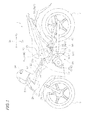
Fig. 1] Fig. 1 is a left side view illustrating a straddle-type vehicle according to one preferred embodiment. - [
Fig. 2] Fig. 2 is a left side view illustrating a body frame and a neighboring region thereof according to one preferred embodiment. - [
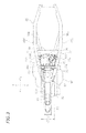
Fig. 3] Fig. 3 is a plan view illustrating the body frame and the neighboring region thereof according to one preferred embodiment. - [
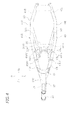
Fig. 4] Fig. 4 is a plan view illustrating the body frame according to one preferred embodiment. - [
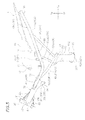
Fig. 5] Fig. 5 is a left side view illustrating the body frame according to one preferred embodiment. - [
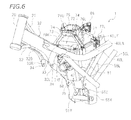
Fig. 6] Fig. 6 is a perspective view illustrating the body frame and the neighboring region thereof according to one preferred embodiment. - [
Fig. 7] Fig. 7 is a perspective view illustrating the body frame and the neighboring region thereof according to one preferred embodiment. - [
Fig. 8] Fig. 8 is a plan view illustrating a lower air cleaner according to one preferred embodiment. - [
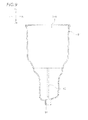
Fig. 9] Fig. 9 is a cross-sectional view taken along line IX-IX inFig. 8 . - [
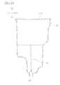
Fig. 10] Fig. 10 is a cross-sectional view taken along line X-X inFig. 8 . - Hereinbelow, preferred embodiments of the present teaching will be described. As illustrated in
Fig. 1 , the straddle-type vehicle according to the present preferred embodiment is an underbone type motorcycle 1. Note that the straddle-type vehicle means a vehicle such that the rider straddles the vehicle when riding. - In the following description, the terms "front," "rear," "left," "right," "up," and "down" respectively refer to front, rear, left, right, up, and down as defined based on the perspective of the rider seated on the
seat 10 of the motorcycle 1, unless specifically indicated otherwise. The terms "above/up" and "below/down" respectively mean the relative vertical positions above/up and below/down as used when the motorcycle 1 is stationary on a horizontal plane. Reference characters F, Re, L, R, Up, and Dn in the drawings indicate front, rear, left, right, up, and down, respectively. - As illustrated in
Fig. 1 , the motorcycle 1 has ahead pipe 20, abody frame 30 connected to thehead pipe 20, aseat 10 for the rider to sit on, and anengine 90. A steering shaft (not shown) is supported by thehead pipe 20. Ahandlebar 24 is provided on an upper portion of the steering shaft. Afront fork 26 is provided on a lower portion of the steering shaft. Afront wheel 5 is supported rotatably at the lower end of thefront fork 26. - As illustrated in
Fig. 2 , thebody frame 30 has amain frame 32, aleft seat frame 40L, aright seat frame 40R (see alsoFig. 3 ), a left downframe 50L, a right downframe 50R (see alsoFig. 4 ), aleft backstay 56L, aright backstay 56R (see alsoFig. 3 ), a left reinforcingframe 58L, and aright reinforcing frame 58R (see alsoFig. 4 ). - As illustrated in
Fig. 1 , the motorcycle 1 has abody cover 28. The body cover 28 is provided over at least one side of each of theleft seat frame 40L and theright seat frame 40R. The body cover 28 is provided over the sides of thehead pipe 20. The body cover 28 is provided over the sides of themain frame 32. The body cover 28 is provided over the sides of theleft seat frame 40L and theright seat frame 40R. The body cover 28 includes anupper surface portion 28U being located rearward of thehead pipe 20 and frontward of theseat 10 and extending rearward and obliquely downward to a position downward relative to theseat 10. Thevehicle body 28 has a recessedportion 29 recessed downward as viewed from the side of the vehicle. The recessedportion 29 is formed behind thehead pipe 20. The recessedportion 29 is formed in front of theseat 10. The recessedportion 29 is formed downward relative to theseat 10. The recessedportion 29 is formed above theengine 90. Because thebody cover 28 is provided with the recessedportion 29, a space is formed between thehead pipe 20 and theseat 10. - As illustrated in
Fig. 2 , theengine 90 has acrankcase 92, acylinder body 94, acylinder head 96, and acylinder head cover 98. Thecylinder body 94 extends upward from a front portion of thecrankcase 92. Thecylinder head 96 is disposed above thecylinder body 94 and joined to thecylinder body 94. Thecylinder head cover 98 is disposed above thecylinder head 96 and joined to thecylinder head 96. Theengine 90 is disposed below themain frame 32. Theengine 90 is directly supported by themain frame 32. Theengine 90 may be indirectly supported by themain frame 32. Theengine 90 is supported by the left downframe 50L and the right downframe 50R. Theengine 90 is supported by a later-describedengine bracket 55, which is provided on the left downframe 50L and the right downframe 50R (see alsoFig. 4 ). More specifically, themain frame 32 has a firstjoint portion 34. The firstjoint portion 34 joins themain frame 32 and theengine 90 to each other. The firstjoint portion 34 joins themain frame 32 and thecylinder head 96 to each other. Theengine bracket 55 includes a secondjoint portion 55A positioned downward and rearward relative to the firstjoint portion 34, and a thirdjoint portion 55B positioned downward relative to the secondjoint portion 55A. The secondjoint portion 55A and the thirdjoint portion 55B join theengine 55 and theengine bracket 55 to each other. The secondjoint portion 55A and the thirdjoint portion 55B join thecrankcase 92 to theengine bracket 55. Theengine 90 may be directly supported by the left downframe 50L and the right downframe 50R. - As illustrated in
Fig. 5 , themain frame 32 is connected to thehead pipe 20. Themain frame 32 and thehead pipe 20 are connected to each other by, for example, welding. Themain frame 32 extends rearward and obliquely downward from thehead pipe 20. Themain frame 32 is formed so that its cross-sectional shape is a rectangular shape. As illustrated inFig. 6 , a rear end portion of themain frame 32 includes a leftvertical wall 32L and a rightvertical wall 32R. The leftvertical wall 32L extends downward. The firstjoint portion 34 is formed in the leftvertical wall 32L. The rightvertical wall 32R extends downward. The firstjoint portion 34 is also formed in the rightvertical wall 32R. As illustrated inFig. 5 , a reinforcingmember 35L is fitted to the leftvertical wall 32L. The reinforcingmember 35L is positioned to the left of the leftvertical wall 32L. A reinforcingmember 35R is fitted to the rightvertical wall 32R. The reinforcingmember 35R is positioned to the right of the rightvertical wall 32R. A vertical midpoint A1 of a portion of themain frame 32 that is connected to thehead pipe 20 is positioned downward relative to an axial midpoint A2 of thehead pipe 20. As illustrated inFig. 3 , a reinforcingmember 33 is fitted to a rear end portion of themain frame 32. The reinforcingmember 33 is fitted to a front end portion of theleft seat frame 40L and a front end portion of theright seat frame 40R. As illustrated inFig. 2 , theengine 90 is not disposed on the extension line of an axial line A3 of themain frame 32. - As illustrated in
Fig. 5 , thebody frame 30 includes a first reinforcingmember 21 and a second reinforcingmember 22. The first reinforcingmember 21 extends rearward and obliquely downward from thehead pipe 20. The first reinforcingmember 21 is connected to thehead pipe 20 and anupper surface 32U of themain frame 32. The second reinforcingmember 22 extends horizontally from thehead pipe 20. The second reinforcingmember 22 is connected to thehead pipe 20 and alower surface 32B of themain frame 32. The second reinforcingmember 22 may extend rearward and obliquely upward from thehead pipe 20. - As illustrated in
Fig. 5 , theleft seat frame 40L is connected to themain frame 32. Theleft seat frame 40L and themain frame 32 are connected to each other by welding. Theleft seat frame 40L and themain frame 32 may be connected to each other by a bolt or the like. Theleft seat frame 40L is formed in a pipe shape. Theleft seat frame 40L is formed so that its cross-sectional shape is circular. Theleft seat frame 40L includes a leftfirst portion 41L and a leftsecond portion 42L. The leftfirst portion 41 L and the leftsecond portion 42L are integrally formed with each other. The leftfirst portion 41 L extends rearward and obliquely downward from themain frame 32. The inclination angle of the leftfirst portion 41 L from the horizontal line is substantially the same as the inclination angle of themain frame 32 from the horizontal line. The leftsecond portion 42L extends rearward and obliquely upward from the left first portion 41 L. The leftfirst portion 41 L of theleft seat frame 40L is connected to themain frame 32 at a position that is frontward relative to the firstjoint portion 34. A lower end 40LB of theleft seat frame 40L is positioned upward relative to the firstjoint portion 34. - As illustrated in
Fig. 4 , theleft seat frame 40L includes a leftthird portion 43L, a leftfourth portion 44L, and a leftfifth portion 45L. The leftthird portion 43L, the leftfourth portion 44L, and the leftfifth portion 45L are integrally formed with each other. The leftthird portion 43L extends rearward and obliquely leftward from themain frame 32. The leftfourth portion 44L extends rearward from the leftthird portion 43L. The leftfifth portion 45L extends rearward and obliquely rightward from the leftfourth portion 44L - As illustrated in
Fig. 5 , theright seat frame 40R is connected to themain frame 32. Theright seat frame 40R and themain frame 32 are connected to each other by welding. Theright seat frame 40R and themain frame 32 may be connected to each other by a bolt or the like. Theright seat frame 40R is formed in a pipe shape. Theright seat frame 40R is formed so that its cross-sectional shape is circular. Theright seat frame 40R is disposed rightward of theleft seat frame 40L. Theright seat frame 40R includes a rightfirst portion 41 R and a rightsecond portion 42R. The rightfirst portion 41 R and the rightsecond portion 42R are integrally formed with each other. The rightfirst portion 41 R extends rearward and obliquely downward from themain frame 32. The inclination angle of the rightfirst portion 41 R from the horizontal line is substantially the same as the inclination angle of themain frame 32 from the horizontal line. The rightsecond portion 42R extends rearward and obliquely upward from the rightfirst portion 41 R. The rightfirst portion 41 R of theright seat frame 40R is connected to themain frame 32 at a position that is frontward relative to the firstjoint portion 34. A lower end 40RB of theright seat frame 40R is positioned upward relative to the firstjoint portion 34. - As illustrated in
Fig. 4 , theright seat frame 40R includes a rightthird portion 43R, a rightfourth portion 44R, and a rightfifth portion 45R. The rightthird portion 43R, the rightfourth portion 44R, and the rightfifth portion 45R are integrally formed with each other. The rightthird portion 43R extends rearward and obliquely rightward from themain frame 32. The rightfourth portion 44R extends rearward from the rightthird portion 43R. The rightfifth portion 45R extends rearward and obliquely leftward from the rightfourth portion 44R. - As illustrated in
Fig. 3 , thebody frame 30 includes afirst cross member 38. Thefirst cross member 38 extends laterally, i.e., in a left-to-right/right-to-left direction. Thefirst cross member 38 is connected to theleft seat frame 40L and theright seat frame 40R. Thefirst cross member 38 is connected to the leftthird portion 43L of theleft seat frame 40L and the rightthird portion 43R of theright seat frame 40R. As illustrated inFig. 5 , thefirst cross member 38 is also connected to the leftsecond portion 42L of theleft seat frame 40L and the rightsecond portion 42R of theright seat frame 40R. - As illustrated in
Fig. 5 , the left downframe 50L is connected to the leftfirst portion 41 L of theleft seat frame 40L. The left downframe 50L and theleft seat frame 40L are connected to each other by, for example, welding. The left downframe 50L is connected to the leftfirst portion 41 L of theleft seat frame 40L at a position upward relative to the firstjoint portion 34. The left downframe 50L is formed in a pipe shape. The left downframe 50L is formed so that its cross-sectional shape is circular. The left downframe 50L is thinner than theleft seat frame 40L. The diameter of the left downframe 50L is smaller than the diameter of theleft seat frame 40L. The left downframe 50L extends rearward and obliquely downward from theleft seat frame 40L. As illustrated inFig. 4 , the left downframe 50L extends inward in a vehicle lateral direction from the leftfirst portion 41 L (seeFig. 5 ) of theleft seat frame 40L. The left downframe 50L extends rearward and obliquely rightward from the leftfirst portion 41 L of theleft seat frame 40L. As viewed in plan of the vehicle, a rear end portion 50LR of the left downframe 50L is positioned between theleft seat frame 40L and theright seat frame 40R. The left downframe 50L may extend rearward, or rearward and obliquely leftward, from theleft seat frame 40L. - As illustrated in
Fig. 5 , the right downframe 50R is connected to the rightfirst portion 41 R of theright seat frame 40R. The right downframe 50R and theright seat frame 40R are connected to each other by, for example, welding. The right downframe 50R is connected to the rightfirst portion 41 R of theright seat frame 40R at a position upward relative to the firstjoint portion 34. The right downframe 50R is formed in a pipe shape. The right downframe 50R is formed so that its cross-sectional shape is circular. The right downframe 50R is thinner than theright seat frame 40R. The diameter of the right downframe 50R is smaller than the diameter of theright seat frame 40R. The right downframe 50R extends rearward and obliquely downward from theright seat frame 40R. As illustrated inFig. 4 , the right downframe 50R is positioned to the right of the left downframe 50L. The right downframe 50R extends inward in a vehicle lateral direction from the rightfirst portion 41 R (seeFig. 5 ) of theright seat frame 40R. The right downframe 50R extends rearward and obliquely leftward from the rightfirst portion 41 R of theright seat frame 40R. As viewed in plan of the vehicle, a rear end portion 50RR of the right downframe 50R is positioned between theleft seat frame 40L and theright seat frame 40R. The right downframe 50R may extend rearward, or rearward and obliquely rightward, from theright seat frame 40R. - As illustrated in
Fig. 5 , thebody frame 30 includes asecond cross member 39. Thesecond cross member 39 extends laterally, i.e., in a left-to-right/right-to-left direction. Thesecond cross member 39 is connected to the left downframe 50L and the right downframe 50R. Thesecond cross member 39 is positioned below thefirst cross member 38. Thesecond cross member 39 is thinner than thefirst cross member 38. - As illustrated in
Fig. 5 , thebody frame 30 has theengine bracket 55. Theengine bracket 55 is provided on the left downframe 50L and the right downframe 50R. Theengine bracket 55 supports a rear end portion of the engine 90 (seeFig. 2 ). Theengine bracket 55 includes aleft plate member 55X, aright plate member 55Y (see alsoFig. 6 ), and arear plate member 55Z. Theleft plate member 55X is connected to the left downframe 50L. Theleft plate member 55X extends downward from the left downframe 50L. Theright plate member 55Y is connected to the right downframe 50R. Theright plate member 55Y extends downward from the right downframe 50R. Theright plate member 55Y is positioned to the right of theleft plate member 55X. Therear plate member 55Z joins the rear end of theleft plate member 55X and the rear end of theright plate member 55Y. Therear plate member 55Z extends in a vertical direction. Each of theleft plate member 55X and theright plate member 55Y has a secondjoint portion 55A and a thirdjoint portion 55B. - As illustrated in
Fig. 1 , the motorcycle 1 has arear arm 60 joined to theengine bracket 55. Theengine bracket 55 and therear arm 60 are joined to each other via apivot shaft 62. Therear arm 60 is joined swingably to theengine bracket 55. Therear arm 60 may be joined swingably to thebody frame 30 or to theengine 90. Arear wheel 7 is supported rotatably at the rear end of therear arm 60. - The
seat 10 is positioned above theleft seat frame 40L and theright seat frame 40R. Theseat 10 is supported by theleft seat frame 40L and theright seat frame 40R. As illustrated inFig. 7 , theseat 10 has abracket 12. Thebracket 12 is disposed on aback surface 11 of theseat 10. Thebracket 12 engages with a later-describedseat support portion 73. As illustrated inFig. 5 , thebracket 12 has a through-hole 13 that penetrates through thebracket 12 in a lateral direction. As illustrated inFig. 7 , thebracket 12 of theseat 10 is joined to theseat support portion 73 by ashaft 78. Theshaft 78 passes through the through-hole 13 (seeFig. 5 ) of thebracket 12 of theseat 10 and through a through-hole 74 of theseat support portion 73. Theshaft 78, thebracket 12, and theseat support portion 73 together form ahinge mechanism 15. Theseat 10 is pivotable about theshaft 78. Thehinge mechanism 15 allows theseat 10 to open and close. Theseat 10 is pivotable about its front end portion. Thebracket 12 may be formed integrally with theseat 10. - As illustrated in
Fig. 2 , the motorcycle 1 has anair cleaner 70. Theair cleaner 70 is disposed below theseat 10. Theair cleaner 70 is disposed rearward of themain frame 32. As illustrated inFig. 3 , theair cleaner 70 is disposed between theleft seat frame 40L and theright seat frame 40R. As illustrated inFig. 2 , theair cleaner 70 is disposed between the left downframe 50L and the right downframe 50R. Theair cleaner 70 is disposed between the left reinforcingframe 58L and theright reinforcing frame 58R. Theair cleaner 70 is disposed rearward relative to at least a portion of theengine 90. Theair cleaner 70 is disposed rearward relative to thecylinder body 94. - As illustrated in
Fig. 2 , theair cleaner 70 includes an upper aircleaner case 71, a lowerair cleaner case 81, and anelement 85. Theelement 85 cleans the air. Theelement 85 is disposed in the lowerair cleaner case 81. Theelement 85 may be disposed in the upper aircleaner case 71. Theelement 85 may be either a dry-type element, that is, an element not impregnated with oil, or a wet-type element, that is, an element impregnated with oil. - The upper air
cleaner case 71 is formed of a material that is harder and more rigid than the material that forms the lowerair cleaner case 81. As illustrated inFig. 3 , the upper aircleaner case 71 is disposed between theleft seat frame 40L and theright seat frame 40R, as viewed in plan of the vehicle. As illustrated inFig. 2 , the lowerair cleaner case 81 is disposed below the upper aircleaner case 71. The lowerair cleaner case 81 is joined to the upper aircleaner case 71. The lowerair cleaner case 81 is disposed between theleft seat frame 40L and theright seat frame 40R. The lowerair cleaner case 81 is disposed between the left downframe 50L and the right downframe 50R. The lowerair cleaner case 81 is disposed between the left reinforcingframe 58L and theright reinforcing frame 58R. A joinedposition 70L between the upper aircleaner case 71 and the lowerair cleaner case 81 is positioned upward relative to a first portion P of each of theleft seat frame 40L and theright seat frame 40R. The first portion P of theleft seat frame 40L is a portion of theleft seat frame 40L in which theleft seat frame 40L overlaps with theair cleaner 70 as viewed from a side of the vehicle. The first portion P of theright seat frame 40R is a portion of theright seat frame 40R in which theright seat frame 40R overlaps with theair cleaner 70 as viewed from a side of the vehicle. The joinedposition 70L is positioned upward relative to thecylinder head cover 98. The joinedposition 70L is positioned upward relative to the firstjoint portion 34. - A
front end portion 71 F of anupper surface 71 U of the upper aircleaner case 71 is recessed downward. Thefront end portion 71 F of theupper surface 71 U of the upper aircleaner case 71 is disposed rearward of the recessedportion 29 of thebody cover 28. The upper aircleaner case 71 has a recessedportion 72, which is recessed across its entire lateral width. The recessedportion 72 is disposed rearward of the recessedportion 29 of thebody cover 28. - As illustrated in
Fig. 2 , the motorcycle 1 has aseat support portion 73. Theseat support portion 73 is formed of a material that is harder and more rigid than the material that forms the lowerair cleaner case 81. It is preferable that the material that forms theseat support portion 73 and the material that forms the lowerair cleaner case 71 be the same. Theseat support portion 73 supports theseat 10 so as to be openable and closable. Theseat support portion 73 is formed integrally with the upper aircleaner case 71. As illustrated inFig. 3 , theseat support portion 73 extends laterally, i.e., in a left-to-right/right-to-left direction. The lateral width L1 of theseat support portion 73 is smaller than the lateral width L2 of thefront end portion 71 F of theupper surface 71 U of the upper aircleaner case 71. A plurality ofribs 75 extending in a vehicle longitudinal direction are formed on theseat support portion 73. Theribs 75 are formed over theseat support portion 73 and the upper aircleaner case 71. As illustrated inFig. 6 , theseat support portion 73 is disposed so as to be spaced from thefront end portion 71 F of theupper surface 71 U of the upper aircleaner case 71. As illustrated inFig. 3 , theseat support portion 73 overlaps with thefront end portion 71 F of theupper surface 71U of the upper aircleaner case 71 as viewed in plan of the vehicle. As illustrated inFig. 6 , theseat support portion 73 has through-holes 71 each penetrating through theseat support portion 73 in a lateral direction. - As illustrated in
Fig. 6 , the motorcycle 1 has a left seatload bearing portion 76L and a right seatload bearing portion 76R. The left seatload bearing portion 76L extends downward from the left end of theseat support portion 73. The left seatload bearing portion 76L inclines from the left end of theseat support portion 73 toward theleft seat frame 40L. As illustrated inFig. 3 , the left seatload bearing portion 76L extends leftward from the left end of theseat support portion 73. The left seatload bearing portion 76L is supported by theleft seat frame 40L. The left seatload bearing portion 76L is supported by a left first support portion 40LX (seeFig. 4 ) provided on theleft seat frame 40L. As illustrated inFig. 2 , the left first support portion 40LX is positioned below theseat support portion 73 as viewed from a side of the vehicle. The left first support portion 40LX is disposed on the above-mentioned first portion P. The body cover 28 (seeFig. 1 ) is provided over a side of the left seatload bearing portion 76L. The body cover 28 is provided leftward of the left seatload bearing portion 76L. The left seatload bearing portion 76L may be supported either directly or indirectly by theleft seat frame 40L. - As illustrated in
Fig. 3 , the right seatload bearing portion 76R is disposed rightward of the left seatload bearing portion 76L. The right seatload bearing portion 76R extends downward from the right end of theseat support portion 73. The right seatload bearing portion 76R inclines from the right end of theseat support portion 73 toward theright seat frame 40R. The right seatload bearing portion 76R extends rightward from the right end of theseat support portion 73. The right seatload bearing portion 76R is supported by theright seat frame 40R. The right seatload bearing portion 76R is supported by a right first support portion 40RX (seeFig. 4 ) provided on theright seat frame 40R. As illustrated inFig. 2 , the right first support portion 40RX is positioned below theseat support portion 73 as viewed from a side of the vehicle. The right first support portion 40RX is disposed on the above-mentioned first portion P. The body cover 28 (seeFig. 1 ) is provided over a side of the right seatload bearing portion 76R. The body cover 28 is provided rightward of the right seatload bearing portion 76R. The right seatload bearing portion 76R may be supported either directly or indirectly by theright seat frame 40R. - As illustrated in
Fig. 3 , the upper aircleaner case 71 has a left securingportion 77L and aright securing portion 77R. Theleft securing portion 77L is disposed rearward of the left seatload bearing portion 76L. Theleft securing portion 77L is supported by theleft seat frame 40L. Theleft securing portion 77L is supported by a left second support portion 40LY (seeFig. 4 ) provided on theleft seat frame 40L. As illustrated inFig. 2 , the left second support portion 40LY is disposed on the above-mentioned first portion P. As illustrated inFig. 3 , theright securing portion 77R is disposed rearward of the right seatload bearing portion 76R. Theright securing portion 77R is supported by theright seat frame 40R. Theright securing portion 77R is supported by a right second support portion 40RY (seeFig. 4 ) provided on theright seat frame 40R. As illustrated inFig. 2 , the right second support portion 40RY is disposed on the above-mentioned first portion P. Theleft securing portion 77L is disposed upward relative to the lower end 76LB of the left seatload bearing portion 76L. Theright securing portion 77R is disposed upward relative to the lower end 76RB of the right seatload bearing portion 76R. -
Fig. 8 is a plan view of the lowerair cleaner case 81. As illustrated inFig. 8 , the lowerair cleaner case 81 has adrain hole 84. Thedrain hole 84 is formed in abottom wall 81 B of the lowerair cleaner case 81. The water that has accumulated in theair cleaner 70 is discharged out of the lowerair cleaner case 81 through thedrain hole 84. The lowerair cleaner case 81 has afirst rib 82 and asecond rib 83. Thefirst rib 82 is formed on aninner wall 81W of the lowerair cleaner case 81. As illustrated inFig. 9 , thefirst rib 82 extends in a vehicle longitudinal direction and in a vertical direction. As illustrated inFig. 10 , thesecond rib 83 is formed on theinner wall 81W of the lowerair cleaner case 81. Thesecond rib 83 extends in a vehicle lateral direction and in a vertical direction. - As illustrated in
Fig. 2 , theair cleaner 70 is provided with afirst intake pipe 86. Thefirst intake pipe 86 is provided on the upper aircleaner case 71. Thefirst intake pipe 86 extends upward. Thefirst intake pipe 86 has an opening facing rearward and obliquely leftward. Theair cleaner 70 is provided with asecond intake pipe 88. Thesecond intake pipe 88 guides the air within theair cleaner 70 toward theengine 90. Thesecond intake pipe 88 is provided on the lowerair cleaner case 81. Thesecond intake pipe 88 extends in a vehicle longitudinal direction. Thesecond intake pipe 88 is connected to thecylinder head 96 via athrottle body 89. - As illustrated in
Fig. 2 , the motorcycle 1 has afuel tank 64. Thefuel tank 64 is disposed rearward of theair cleaner 70. Thefuel tank 64 is disposed below theseat 10. Thetop end 71T of the upper aircleaner case 71 is positioned upward relative to the verticallycentral position 64C of thefuel tank 64. The height difference H1 between thetop end 71T of the upper aircleaner case 71 and thetop end 64T of thefuel tank 64 is smaller than the height difference H2 between thetop end 71T of the upper aircleaner case 71 and the verticallycentral position 64C of thefuel tank 64. Thebottom end 64B of thefuel tank 64 is positioned downward relative to thetop end 81T of the lowerair cleaner case 81. - As illustrated in
Fig. 2 , theleft backstay 56L extends rearward and obliquely upward from the left downframe 50L. As illustrated inFig. 4 , theleft backstay 56L extends rearward and obliquely leftward from the left downframe 50L. As illustrated inFig. 2 , theleft backstay 56L joins the left downframe 50L and the leftsecond portion 42L of theleft seat frame 40L to each other. As viewed from a side of the vehicle, a leftjoint portion 57L joining theleft backstay 56L and the leftsecond portion 42L of theleft seat frame 40L to each other overlaps with thefuel tank 64. - As illustrated in
Fig. 2 , theright backstay 56R extends rearward and obliquely upward from the right downframe 50R. As illustrated inFig. 4 , theright backstay 56R extends rearward and obliquely rightward from the right downframe 50R. Theright backstay 56R is positioned rightward of theleft backstay 56L. As illustrated inFig. 2 , theright backstay 56R joins the right downframe 50R and the rightsecond portion 42R of theright seat frame 40R to each other. As viewed from a side of the vehicle, a rightjoint portion 57R joining theright backstay 56R and the rightsecond portion 42R of theright seat frame 40R to each other overlaps with thefuel tank 64. - As illustrated in
Fig. 2 , theleft reinforcing frame 58L is disposed frontward relative to theleft backstay 56L. The left reinforcingframe 58L joins the left downframe 50L and the leftsecond portion 42L of theleft seat frame 40L to each other. The left reinforcingframe 58L extends rearward and obliquely upward from the left downframe 50L. As illustrated inFig. 4 , theleft reinforcing frame 58L extends rearward and obliquely leftward from the left downframe 50L. The left reinforcingframe 58L may join the left downframe 50L and the leftfirst portion 41 L (seeFig. 2 ) of theleft seat frame 40L to each other. - As illustrated in
Fig. 4 , theright reinforcing frame 58R is positioned rightward of the left reinforcingframe 58L. As illustrated inFig. 2 , theright reinforcing frame 58R is disposed frontward relative to theright backstay 56R. Theright reinforcing frame 58R joins the right downframe 50R and the rightsecond portion 42R of theright seat frame 40R to each other. Theright reinforcing frame 58R extends rearward and obliquely upward from the right downframe 50R. As illustrated inFig. 4 , theright reinforcing frame 58R extends rearward and obliquely rightward from the right downframe 50R. Theright reinforcing frame 58R may join the right downframe 50R and the rightfirst portion 41 R (seeFig. 2 ) of theright seat frame 40R to each other. - As thus far described, in the motorcycle 1, the left
first portion 41 L of theleft seat frame 40L is connected to themain frame 32, and the rightfirst portion 41 R of theright seat frame 40R is connected to themain frame 32, as illustrated inFig. 2 . Therefore, part of the load applied to theseat 10, which is supported by the left and right seat frames 40L and 40R, is transmitted to themain frame 32. Because the cross-sectional shape of themain frame 32 is a rectangular shape, themain frame 32 has higher rigidity than when its cross-sectional shape is a circular shape. Moreover, because themain frame 32 has a rectangular cross-sectional shape, it is easier to join themain frame 32 to the left and right seat frames 40L and 40R than when its cross-sectional shape is a circular shape. Also, higher bonding strength is obtained when themain frame 32 is joined to theleft seat frame 40L and theright seat frame 40R by welding or the like. Furthermore, because part of the load applied to theseat 10 is transmitted to themain frame 32, the load applied to the left downframe 50L, which is connected to the leftfirst portion 41 L of theleft seat frame 40L, and the load applied to the right downframe 50R, which is connected to the rightfirst portion 41 R of the right seat frame 40, are reduced. As a result, the left and right down frames 50L and 50R have sufficient rigidity even when the left and right down frames 50L and 50R are formed thinner, in contrast to the case where the left and right seat frames 40L and 40R are not connected to themain frame 32. As described above, in the motorcycle 1. theleft seat frame 40L and theright seat frame 40R are connected to themain frame 32 with high rigidity. For this reason, even when the left and right down frames 50L and 50R, which are connected respectively to the left and rightfirst portions body frame 30 as a whole can be ensured sufficiently. As a result, it becomes possible to provide the motorcycle 1 in which theengine 90 of a relatively large size is supported by the left and right down frames 50R and 50L. In addition, it may appear that the left downframe 50L and the right downframe 50R extending laterally inward can reduce the volumetric capacity of theair cleaner 70, which is disposed between the left downframe 50L and the right downframe 50R. However, because the left downframe 50L can be formed thinner than theleft seat frame 40L and the right downframe 50R can also be formed thinner than theright seat frame 40R, the volumetric capacity of theair cleaner 70, which is disposed between the left downframe 50L and the right downframe 50R, can be made larger than the case where the left downframe 50L and the right downframe 50R are formed thicker. - In the motorcycle 1 according to the present preferred embodiment, the left
first portion 41L of theleft seat frame 40L and the rightfirst portion 41 R of theright seat frame 40R are connected to themain frame 32 at respective positions frontward relative to the firstjoint portion 34, as illustrated inFig. 2 . This makes it possible to increase the rigidity of themain frame 32, theleft seat frame 40L, and theright seat frame 40R. - In the motorcycle 1 according to the present preferred embodiment, the left down
frame 50L is connected to the leftfirst portion 41 L at a position upward relative to the firstjoint portion 34, and the right downframe 50R is connected to the rightfirst portion 41 R of theright seat frame 40R at a position upward relative to the firstjoint portion 34, as illustrated inFig. 2 . This makes it possible to increase the rigidity of the left downframe 50L and the right downframe 50R. - In the motorcycle 1 according to the present preferred embodiment, the lower end 40LB of the
left seat frame 40L and the lower end 40RB of theright seat frame 40R are positioned upward relative to the firstjoint portion 34, as illustrated inFig. 2 . This makes it possible to support theair cleaner 70 stably, even when a portion of theair cleaner 70 is positioned upward relative to theleft seat frame 40L and theright seat frame 40R while theengine 90 is disposed at a low position. - In the motorcycle 1 according to the present preferred embodiment, as viewed from a side of the vehicle, the left
joint portion 57L joining theleft backstay 56L and the leftsecond portion 42L of theleft seat frame 40L to each other overlaps thefuel tank 64, and the rightjoint portion 57R joining theright backstay 56R and the rightsecond portion 42R of theright seat frame 40R to each other overlaps thefuel tank 64, as illustrated inFig. 2 . Part of the seat load applied to theleft seat frame 40L and theright seat frame 40R is transmitted to themain frame 32. For this reason, theleft seat frame 40L and theright seat frame 40R can withstand the load from theseat 10 even when they have relatively low rigidity. As a result, the leftjoint portion 57L and the rightjoint portion 57R need not be positioned rearward relative to thefuel tank 64 in order to increase the rigidity of theleft seat frame 40L and theright seat frame 40R. Therefore, theleft backstay 56L and theright backstay 56R can be made shorter. In other words, a weight reduction of theleft backstay 56L and theright backstay 56R can be achieved. Moreover, it is possible to provide a space behind theleft backstay 56L and theright backstay 56R. - In the motorcycle 1 according to the present preferred embodiment, the
left reinforcing frame 58L and theright reinforcing frame 58R respectively join theleft seat frame 40L and the left downframe 50L to each other and theright seat frame 40R and the right downframe 50R to each other, as illustrated inFig. 2 . This makes it possible to form the left downframe 50L and the right downframe 50R to be thinner while ensuring sufficient rigidity of the left downframe 50L and the right downframe 50R. - In the motorcycle 1 according to the present preferred embodiment, the axial midpoint A2 of the
head pipe 20 is positioned upward relative to the vertical midpoint A1 of the portion of themain frame 32 that is connected to thehead pipe 20, as illustrated inFig. 5 . This enables thehead pipe 20 and themain frame 32 to have an appropriate level of rigidity. - The motorcycle 1 according to the present preferred embodiment has the first reinforcing
member 21 connecting thehead pipe 20 and theupper surface 32U of themain frame 32 to each other and the second reinforcingmember 22 connecting thehead pipe 20 and thelower surface 32B of themain frame 32 to each other. This enables thehead pipe 20 and themain frame 32 to have higher rigidity. - In the motorcycle 1 according to the present preferred embodiment, the
engine 90 is directly supported by themain frame 32, as illustrated inFig. 2 . This achieves a reduction in the number of members that are necessary in connecting theengine 90 to themain frame 32. As a result, a reduction in the overall weight of the motorcycle 1 and simplification of the structure are achieved. -
- 32
- Main frame
- 34
- First joint portion
- 40L
- Left seat frame
- 40R
- Right seat frame
- 41L
- Left first portion
- 41R
- Right first portion
- 42L
- Left second portion
- 42R
- Right second portion
- 50L
- Left down frame
- 50R
- Right down frame
- 70
- Air cleaner
- 90
- Engine
Claims (9)
- A straddle-type vehicle (1) comprising:a head pipe (20);a main frame (32) being connected to the head pipe (20), extending rearward andobliquely downward from the head pipe (20), and having a rectangular cross-sectional shape;a left seat frame (40L) being connected to the main frame (32) and comprising a left first portion (41 L) and a left second portion (42L), the left first portion (41 L) extending rearward and obliquely downward from the main frame (32), and the left second portion (42L) formed integrally with the left first portion (41 L) and extending rearward and obliquely upward from the left first portion (41L);a right seat frame (40R) being connected to the main frame (32) and comprising a right first portion (41R) and a right second portion (42R), the right first portion (41 R) extending rearward and obliquely downward from the main frame (32), and the right second portion (42R) formed integrally with the right first portion (41R) and extending rearward and obliquely upward from the right first portion (41 R), the right seat frame (40R) being disposed rightward of the left seat frame (40L);a left down frame (50L), being connected to the left first portion (41 L) of the left seat frame (40L), extending rearward and obliquely downward from the left seat frame (40L), and being thinner than the left seat frame (40L);a right down frame (50R), being connected to the right first portion (41 R) of the right seat frame (40R), extending rearward and obliquely downward from the right seat frame (40R), being disposed rightward of the left down frame (50L), and being thinner than the right seat frame (40R);a seat (10) supported by the left seat frame (40L) and the right seat frame (40R);a body cover (28) being provided over at least one side of each of the left seat frame (40L) and the right seat frame (40R), and including an upper surface portion (28U) being located rearward of the head pipe (20) and frontward of the seat (10) andextending rearward and obliquely downward to a position downward relative to the seat (10);an engine (90) disposed below the left down frame (50L) and the right down frame (50R) and supported by the left down frame (50L) and the right down frame (50R); andan air cleaner (70) disposed rearward relative to at least a portion of the engine (90) and disposed between the left seat frame (40L) and the right seat frame (40R) and between the left down frame (50L) and the right down frame (50R), whereinthe left down frame (50L) extends inward in a vehicle lateral direction from the left first portion (41 L) of the left seat frame (40L);a rear end portion (50LR) of the left down frame (50L) is positioned between the left seat frame (40L) and the right seat frame (40R) as viewed in plan of the vehicle;the right down frame (50R) extends inward in a vehicle lateral direction from the right first portion (41 R) of the right seat frame (40R); anda rear end portion (50RR) of the right down frame (50R) is positioned between the left seat frame (40L) and the right seat frame (40R) as viewed in plan of the vehicle.
- A straddle-type vehicle according to claim 1, wherein the main frame (32) includes a joint portion (34) joined to the engine (90); and
the left first portion (41 L) of the left seat frame (40L) and the right first portion (41 R) of the right seat frame (40R) are connected to the main frame (32) at respective positions frontward relative to the joint portion (34). - A straddle-type vehicle according to claim 2, wherein the left down frame (50L) is connected to the left first portion (41 L) of the left seat frame (40L) at a position upward relative to the joint portion (34); and
the right down frame (50R) is connected to the right first portion (41 R) of the right seat frame (40R) at a position upward relative to the joint portion (34). - A straddle-type vehicle according to claim 2 or 3, wherein the left seat frame (40L) has a lower end (40LB) positioned upward relative to the joint portion (34), and the right seat frame (40R) has a lower end (40RB) positioned upward relative to the joint portion (34).
- A straddle-type vehicle according to any one of claims 1 to 4, further comprising:a fuel tank (64) disposed rearward of the air cleaner (70);a left backstay (56L) joining the left down frame (50L) and the left second portion (42L) of the left seat frame (40L) to each other; anda right backstay (56R) joining the right down frame (50R) and the right second portion (42R) of the right seat frame (40R) to each other, whereinas viewed from a side of the vehicle, a left joint portion (57L) joining the left backstay (56L) and the left second portion (42L) of the left seat frame (40L) to each other overlaps the fuel tank (64), and a right joint portion (57R) joining the right backstay (56R) and the right second portion (42R) of the right seat frame (40R) to each other overlaps the fuel tank (64).
- A straddle-type vehicle according to claim 5, further comprising:a left reinforcing frame (58L) being disposed frontward relative to the left backstay (56L) and joining the left seat frame (40L) and the left down frame (50L) to each other; anda right reinforcing frame (58R) being disposed frontward relative to the right backstay (56R) and rightward of the left reinforcing frame (58L), and joining the right seat frame (40R) and the right down frame (50R) to each other.
- A straddle-type vehicle according to any one of claims 1 to 6, wherein an axial midpoint (A2) of the head pipe (20) is positioned upward relative to a vertical midpoint (A1) of a portion of the main frame (32) that is connected to the head pipe (20).
- A straddle-type vehicle according to any one of claims 1 to 7, further comprising:a first reinforcing member (21) connecting the head pipe (20) and an upper surface (32U) of the main frame (32) to each other; anda second reinforcing member (22) connecting the head pipe (20) and a lower surface (32B) of the main frame (32) to each other.
- A straddle-type vehicle according to any one of claims 1 to 8, wherein the engine (90) is supported directly by the main frame (32).
Applications Claiming Priority (1)
| Application Number | Priority Date | Filing Date | Title |
|---|---|---|---|
| JP2014108808A JP2015223899A (en) | 2014-05-27 | 2014-05-27 | Saddle riding type vehicle |
Publications (2)
| Publication Number | Publication Date |
|---|---|
| EP2949563A1 true EP2949563A1 (en) | 2015-12-02 |
| EP2949563B1 EP2949563B1 (en) | 2016-06-01 |
Family
ID=53269322
Family Applications (1)
| Application Number | Title | Priority Date | Filing Date |
|---|---|---|---|
| EP15169158.1A Active EP2949563B1 (en) | 2014-05-27 | 2015-05-26 | Straddle-type vehicle |
Country Status (3)
| Country | Link |
|---|---|
| EP (1) | EP2949563B1 (en) |
| JP (1) | JP2015223899A (en) |
| ES (1) | ES2576194T3 (en) |
Citations (3)
| Publication number | Priority date | Publication date | Assignee | Title |
|---|---|---|---|---|
| JP2006088892A (en) | 2004-09-24 | 2006-04-06 | Yamaha Motor Co Ltd | Saddle riding vehicle |
| TW200804128A (en) * | 2006-07-06 | 2008-01-16 | Kwang Yang Motor Co | Motorcycle frame device |
| WO2013008815A1 (en) * | 2011-07-11 | 2013-01-17 | 本田技研工業株式会社 | Saddle-riding-type motorcycle |
-
2014
- 2014-05-27 JP JP2014108808A patent/JP2015223899A/en active Pending
-
2015
- 2015-05-26 EP EP15169158.1A patent/EP2949563B1/en active Active
- 2015-05-26 ES ES15169158.1T patent/ES2576194T3/en active Active
Patent Citations (3)
| Publication number | Priority date | Publication date | Assignee | Title |
|---|---|---|---|---|
| JP2006088892A (en) | 2004-09-24 | 2006-04-06 | Yamaha Motor Co Ltd | Saddle riding vehicle |
| TW200804128A (en) * | 2006-07-06 | 2008-01-16 | Kwang Yang Motor Co | Motorcycle frame device |
| WO2013008815A1 (en) * | 2011-07-11 | 2013-01-17 | 本田技研工業株式会社 | Saddle-riding-type motorcycle |
Also Published As
| Publication number | Publication date |
|---|---|
| JP2015223899A (en) | 2015-12-14 |
| ES2576194T3 (en) | 2016-07-06 |
| EP2949563B1 (en) | 2016-06-01 |
Similar Documents
| Publication | Publication Date | Title |
|---|---|---|
| JP5969232B2 (en) | Radiator hose layout structure for saddle-ride type vehicles | |
| JP5916456B2 (en) | Wind exhaust structure for radiators of saddle-ride type vehicles | |
| JP5925547B2 (en) | Wind guide structure for saddle-ride type vehicles | |
| EP2457815B1 (en) | Saddle-ride type vehicle | |
| EP2974948B1 (en) | Straddle-type vehicle | |
| EP2949564B1 (en) | Vehicle | |
| EP2955088B1 (en) | Straddle-type vehicle | |
| EP2679476B1 (en) | Motorcycle | |
| JP2007326505A (en) | Motorcycle | |
| US9428238B2 (en) | Body frame structure for saddle type vehicle | |
| JP5893459B2 (en) | Fuel tank and radiator arrangement structure for saddle-ride type vehicles | |
| EP2949563B1 (en) | Straddle-type vehicle | |
| JP2016020182A (en) | Saddle-riding type vehicle | |
| EP2543581A1 (en) | Cowl structure of saddle-ride type vehicle | |
| JP6159604B2 (en) | Motorcycle body frame | |
| JP6535764B2 (en) | Fuel tank structure of straddle type vehicle | |
| JP5894826B2 (en) | Lift-up support structure for saddle-ride type vehicles | |
| EP2639145B1 (en) | Straddle-type vehicle | |
| EP3000702A1 (en) | Saddle-riding type vehicle | |
| EP3305639B1 (en) | Straddled vehicle | |
| JP7178392B2 (en) | saddle-riding vehicle | |
| EP2878523A1 (en) | Straddle-type vehicle | |
| EP2679477B1 (en) | Motorcycle |
Legal Events
| Date | Code | Title | Description |
|---|---|---|---|
| AK | Designated contracting states |
Kind code of ref document: A1 Designated state(s): AL AT BE BG CH CY CZ DE DK EE ES FI FR GB GR HR HU IE IS IT LI LT LU LV MC MK MT NL NO PL PT RO RS SE SI SK SM TR |
|
| AX | Request for extension of the european patent |
Extension state: BA ME |
|
| PUAI | Public reference made under article 153(3) epc to a published international application that has entered the european phase |
Free format text: ORIGINAL CODE: 0009012 |
|
| 17P | Request for examination filed |
Effective date: 20151223 |
|
| RBV | Designated contracting states (corrected) |
Designated state(s): AL AT BE BG CH CY CZ DE DK EE ES FI FR GB GR HR HU IE IS IT LI LT LU LV MC MK MT NL NO PL PT RO RS SE SI SK SM TR |
|
| GRAP | Despatch of communication of intention to grant a patent |
Free format text: ORIGINAL CODE: EPIDOSNIGR1 |
|
| RIC1 | Information provided on ipc code assigned before grant |
Ipc: B62K 11/04 20060101AFI20160209BHEP Ipc: F02M 35/16 20060101ALI20160209BHEP |
|
| INTG | Intention to grant announced |
Effective date: 20160302 |
|
| GRAS | Grant fee paid |
Free format text: ORIGINAL CODE: EPIDOSNIGR3 |
|
| GRAA | (expected) grant |
Free format text: ORIGINAL CODE: 0009210 |
|
| AK | Designated contracting states |
Kind code of ref document: B1 Designated state(s): AL AT BE BG CH CY CZ DE DK EE ES FI FR GB GR HR HU IE IS IT LI LT LU LV MC MK MT NL NO PL PT RO RS SE SI SK SM TR |
|
| REG | Reference to a national code |
Ref country code: GB Ref legal event code: FG4D |
|
| REG | Reference to a national code |
Ref country code: CH Ref legal event code: EP Ref country code: AT Ref legal event code: REF Ref document number: 803701 Country of ref document: AT Kind code of ref document: T Effective date: 20160615 |
|
| REG | Reference to a national code |
Ref country code: IE Ref legal event code: FG4D |
|
| REG | Reference to a national code |
Ref country code: ES Ref legal event code: FG2A Ref document number: 2576194 Country of ref document: ES Kind code of ref document: T3 Effective date: 20160706 |
|
| REG | Reference to a national code |
Ref country code: DE Ref legal event code: R096 Ref document number: 602015000056 Country of ref document: DE |
|
| REG | Reference to a national code |
Ref country code: LT Ref legal event code: MG4D |
|
| REG | Reference to a national code |
Ref country code: NL Ref legal event code: MP Effective date: 20160601 |
|
| PG25 | Lapsed in a contracting state [announced via postgrant information from national office to epo] |
Ref country code: NO Free format text: LAPSE BECAUSE OF FAILURE TO SUBMIT A TRANSLATION OF THE DESCRIPTION OR TO PAY THE FEE WITHIN THE PRESCRIBED TIME-LIMIT Effective date: 20160901 Ref country code: LT Free format text: LAPSE BECAUSE OF FAILURE TO SUBMIT A TRANSLATION OF THE DESCRIPTION OR TO PAY THE FEE WITHIN THE PRESCRIBED TIME-LIMIT Effective date: 20160601 Ref country code: FI Free format text: LAPSE BECAUSE OF FAILURE TO SUBMIT A TRANSLATION OF THE DESCRIPTION OR TO PAY THE FEE WITHIN THE PRESCRIBED TIME-LIMIT Effective date: 20160601 |
|
| REG | Reference to a national code |
Ref country code: AT Ref legal event code: MK05 Ref document number: 803701 Country of ref document: AT Kind code of ref document: T Effective date: 20160601 |
|
| PG25 | Lapsed in a contracting state [announced via postgrant information from national office to epo] |
Ref country code: HR Free format text: LAPSE BECAUSE OF FAILURE TO SUBMIT A TRANSLATION OF THE DESCRIPTION OR TO PAY THE FEE WITHIN THE PRESCRIBED TIME-LIMIT Effective date: 20160601 Ref country code: RS Free format text: LAPSE BECAUSE OF FAILURE TO SUBMIT A TRANSLATION OF THE DESCRIPTION OR TO PAY THE FEE WITHIN THE PRESCRIBED TIME-LIMIT Effective date: 20160601 Ref country code: LV Free format text: LAPSE BECAUSE OF FAILURE TO SUBMIT A TRANSLATION OF THE DESCRIPTION OR TO PAY THE FEE WITHIN THE PRESCRIBED TIME-LIMIT Effective date: 20160601 Ref country code: GR Free format text: LAPSE BECAUSE OF FAILURE TO SUBMIT A TRANSLATION OF THE DESCRIPTION OR TO PAY THE FEE WITHIN THE PRESCRIBED TIME-LIMIT Effective date: 20160902 Ref country code: SE Free format text: LAPSE BECAUSE OF FAILURE TO SUBMIT A TRANSLATION OF THE DESCRIPTION OR TO PAY THE FEE WITHIN THE PRESCRIBED TIME-LIMIT Effective date: 20160601 Ref country code: NL Free format text: LAPSE BECAUSE OF FAILURE TO SUBMIT A TRANSLATION OF THE DESCRIPTION OR TO PAY THE FEE WITHIN THE PRESCRIBED TIME-LIMIT Effective date: 20160601 |
|
| PG25 | Lapsed in a contracting state [announced via postgrant information from national office to epo] |
Ref country code: SK Free format text: LAPSE BECAUSE OF FAILURE TO SUBMIT A TRANSLATION OF THE DESCRIPTION OR TO PAY THE FEE WITHIN THE PRESCRIBED TIME-LIMIT Effective date: 20160601 Ref country code: RO Free format text: LAPSE BECAUSE OF FAILURE TO SUBMIT A TRANSLATION OF THE DESCRIPTION OR TO PAY THE FEE WITHIN THE PRESCRIBED TIME-LIMIT Effective date: 20160601 Ref country code: EE Free format text: LAPSE BECAUSE OF FAILURE TO SUBMIT A TRANSLATION OF THE DESCRIPTION OR TO PAY THE FEE WITHIN THE PRESCRIBED TIME-LIMIT Effective date: 20160601 Ref country code: CZ Free format text: LAPSE BECAUSE OF FAILURE TO SUBMIT A TRANSLATION OF THE DESCRIPTION OR TO PAY THE FEE WITHIN THE PRESCRIBED TIME-LIMIT Effective date: 20160601 Ref country code: IS Free format text: LAPSE BECAUSE OF FAILURE TO SUBMIT A TRANSLATION OF THE DESCRIPTION OR TO PAY THE FEE WITHIN THE PRESCRIBED TIME-LIMIT Effective date: 20161001 |
|
| PG25 | Lapsed in a contracting state [announced via postgrant information from national office to epo] |
Ref country code: PL Free format text: LAPSE BECAUSE OF FAILURE TO SUBMIT A TRANSLATION OF THE DESCRIPTION OR TO PAY THE FEE WITHIN THE PRESCRIBED TIME-LIMIT Effective date: 20160601 Ref country code: SM Free format text: LAPSE BECAUSE OF FAILURE TO SUBMIT A TRANSLATION OF THE DESCRIPTION OR TO PAY THE FEE WITHIN THE PRESCRIBED TIME-LIMIT Effective date: 20160601 Ref country code: BE Free format text: LAPSE BECAUSE OF FAILURE TO SUBMIT A TRANSLATION OF THE DESCRIPTION OR TO PAY THE FEE WITHIN THE PRESCRIBED TIME-LIMIT Effective date: 20160601 Ref country code: PT Free format text: LAPSE BECAUSE OF FAILURE TO SUBMIT A TRANSLATION OF THE DESCRIPTION OR TO PAY THE FEE WITHIN THE PRESCRIBED TIME-LIMIT Effective date: 20161003 Ref country code: AT Free format text: LAPSE BECAUSE OF FAILURE TO SUBMIT A TRANSLATION OF THE DESCRIPTION OR TO PAY THE FEE WITHIN THE PRESCRIBED TIME-LIMIT Effective date: 20160601 |
|
| REG | Reference to a national code |
Ref country code: DE Ref legal event code: R097 Ref document number: 602015000056 Country of ref document: DE |
|
| PLBE | No opposition filed within time limit |
Free format text: ORIGINAL CODE: 0009261 |
|
| STAA | Information on the status of an ep patent application or granted ep patent |
Free format text: STATUS: NO OPPOSITION FILED WITHIN TIME LIMIT |
|
| 26N | No opposition filed |
Effective date: 20170302 |
|
| PG25 | Lapsed in a contracting state [announced via postgrant information from national office to epo] |
Ref country code: DK Free format text: LAPSE BECAUSE OF FAILURE TO SUBMIT A TRANSLATION OF THE DESCRIPTION OR TO PAY THE FEE WITHIN THE PRESCRIBED TIME-LIMIT Effective date: 20160601 Ref country code: SI Free format text: LAPSE BECAUSE OF FAILURE TO SUBMIT A TRANSLATION OF THE DESCRIPTION OR TO PAY THE FEE WITHIN THE PRESCRIBED TIME-LIMIT Effective date: 20160601 |
|
| PG25 | Lapsed in a contracting state [announced via postgrant information from national office to epo] |
Ref country code: LU Free format text: LAPSE BECAUSE OF NON-PAYMENT OF DUE FEES Effective date: 20170531 |
|
| REG | Reference to a national code |
Ref country code: DE Ref legal event code: R119 Ref document number: 602015000056 Country of ref document: DE |
|
| PG25 | Lapsed in a contracting state [announced via postgrant information from national office to epo] |
Ref country code: MC Free format text: LAPSE BECAUSE OF FAILURE TO SUBMIT A TRANSLATION OF THE DESCRIPTION OR TO PAY THE FEE WITHIN THE PRESCRIBED TIME-LIMIT Effective date: 20160601 |
|
| REG | Reference to a national code |
Ref country code: IE Ref legal event code: MM4A |
|
| REG | Reference to a national code |
Ref country code: FR Ref legal event code: ST Effective date: 20180131 |
|
| PG25 | Lapsed in a contracting state [announced via postgrant information from national office to epo] |
Ref country code: LU Free format text: LAPSE BECAUSE OF NON-PAYMENT OF DUE FEES Effective date: 20170526 |
|
| PG25 | Lapsed in a contracting state [announced via postgrant information from national office to epo] |
Ref country code: DE Free format text: LAPSE BECAUSE OF NON-PAYMENT OF DUE FEES Effective date: 20171201 Ref country code: IE Free format text: LAPSE BECAUSE OF NON-PAYMENT OF DUE FEES Effective date: 20170526 |
|
| PG25 | Lapsed in a contracting state [announced via postgrant information from national office to epo] |
Ref country code: FR Free format text: LAPSE BECAUSE OF NON-PAYMENT OF DUE FEES Effective date: 20170531 |
|
| PG25 | Lapsed in a contracting state [announced via postgrant information from national office to epo] |
Ref country code: MT Free format text: LAPSE BECAUSE OF NON-PAYMENT OF DUE FEES Effective date: 20170526 |
|
| PG25 | Lapsed in a contracting state [announced via postgrant information from national office to epo] |
Ref country code: AL Free format text: LAPSE BECAUSE OF FAILURE TO SUBMIT A TRANSLATION OF THE DESCRIPTION OR TO PAY THE FEE WITHIN THE PRESCRIBED TIME-LIMIT Effective date: 20160601 |
|
| REG | Reference to a national code |
Ref country code: CH Ref legal event code: PL |
|
| PG25 | Lapsed in a contracting state [announced via postgrant information from national office to epo] |
Ref country code: CH Free format text: LAPSE BECAUSE OF NON-PAYMENT OF DUE FEES Effective date: 20180531 Ref country code: LI Free format text: LAPSE BECAUSE OF NON-PAYMENT OF DUE FEES Effective date: 20180531 |
|
| PG25 | Lapsed in a contracting state [announced via postgrant information from national office to epo] |
Ref country code: HU Free format text: LAPSE BECAUSE OF FAILURE TO SUBMIT A TRANSLATION OF THE DESCRIPTION OR TO PAY THE FEE WITHIN THE PRESCRIBED TIME-LIMIT; INVALID AB INITIO Effective date: 20150526 |
|
| PG25 | Lapsed in a contracting state [announced via postgrant information from national office to epo] |
Ref country code: BG Free format text: LAPSE BECAUSE OF FAILURE TO SUBMIT A TRANSLATION OF THE DESCRIPTION OR TO PAY THE FEE WITHIN THE PRESCRIBED TIME-LIMIT Effective date: 20160601 |
|
| PG25 | Lapsed in a contracting state [announced via postgrant information from national office to epo] |
Ref country code: CY Free format text: LAPSE BECAUSE OF FAILURE TO SUBMIT A TRANSLATION OF THE DESCRIPTION OR TO PAY THE FEE WITHIN THE PRESCRIBED TIME-LIMIT Effective date: 20160601 |
|
| PG25 | Lapsed in a contracting state [announced via postgrant information from national office to epo] |
Ref country code: MK Free format text: LAPSE BECAUSE OF FAILURE TO SUBMIT A TRANSLATION OF THE DESCRIPTION OR TO PAY THE FEE WITHIN THE PRESCRIBED TIME-LIMIT Effective date: 20160601 |
|
| GBPC | Gb: european patent ceased through non-payment of renewal fee |
Effective date: 20190526 |
|
| PG25 | Lapsed in a contracting state [announced via postgrant information from national office to epo] |
Ref country code: GB Free format text: LAPSE BECAUSE OF NON-PAYMENT OF DUE FEES Effective date: 20190526 |
|
| P01 | Opt-out of the competence of the unified patent court (upc) registered |
Effective date: 20230527 |
|
| PGFP | Annual fee paid to national office [announced via postgrant information from national office to epo] |
Ref country code: ES Payment date: 20250627 Year of fee payment: 11 |
|
| PGFP | Annual fee paid to national office [announced via postgrant information from national office to epo] |
Ref country code: IT Payment date: 20250527 Year of fee payment: 11 |
|
| PGFP | Annual fee paid to national office [announced via postgrant information from national office to epo] |
Ref country code: TR Payment date: 20250520 Year of fee payment: 11 |