EP2949549A1 - Vehicle body front structure - Google Patents
Vehicle body front structure Download PDFInfo
- Publication number
- EP2949549A1 EP2949549A1 EP14742925.2A EP14742925A EP2949549A1 EP 2949549 A1 EP2949549 A1 EP 2949549A1 EP 14742925 A EP14742925 A EP 14742925A EP 2949549 A1 EP2949549 A1 EP 2949549A1
- Authority
- EP
- European Patent Office
- Prior art keywords
- front side
- vehicle
- spacer
- coupling member
- longitudinal direction
- Prior art date
- Legal status (The legal status is an assumption and is not a legal conclusion. Google has not performed a legal analysis and makes no representation as to the accuracy of the status listed.)
- Granted
Links
Images







Classifications
-
- B—PERFORMING OPERATIONS; TRANSPORTING
- B60—VEHICLES IN GENERAL
- B60R—VEHICLES, VEHICLE FITTINGS, OR VEHICLE PARTS, NOT OTHERWISE PROVIDED FOR
- B60R19/00—Wheel guards; Radiator guards, e.g. grilles; Obstruction removers; Fittings damping bouncing force in collisions
- B60R19/02—Bumpers, i.e. impact receiving or absorbing members for protecting vehicles or fending off blows from other vehicles or objects
- B60R19/24—Arrangements for mounting bumpers on vehicles
- B60R19/26—Arrangements for mounting bumpers on vehicles comprising yieldable mounting means
- B60R19/34—Arrangements for mounting bumpers on vehicles comprising yieldable mounting means destroyed upon impact, e.g. one-shot type
-
- B—PERFORMING OPERATIONS; TRANSPORTING
- B60—VEHICLES IN GENERAL
- B60R—VEHICLES, VEHICLE FITTINGS, OR VEHICLE PARTS, NOT OTHERWISE PROVIDED FOR
- B60R19/00—Wheel guards; Radiator guards, e.g. grilles; Obstruction removers; Fittings damping bouncing force in collisions
- B60R19/02—Bumpers, i.e. impact receiving or absorbing members for protecting vehicles or fending off blows from other vehicles or objects
- B60R19/04—Bumpers, i.e. impact receiving or absorbing members for protecting vehicles or fending off blows from other vehicles or objects formed from more than one section in a side-by-side arrangement
- B60R19/12—Bumpers, i.e. impact receiving or absorbing members for protecting vehicles or fending off blows from other vehicles or objects formed from more than one section in a side-by-side arrangement vertically spaced
-
- B—PERFORMING OPERATIONS; TRANSPORTING
- B62—LAND VEHICLES FOR TRAVELLING OTHERWISE THAN ON RAILS
- B62D—MOTOR VEHICLES; TRAILERS
- B62D21/00—Understructures, i.e. chassis frame on which a vehicle body may be mounted
- B62D21/15—Understructures, i.e. chassis frame on which a vehicle body may be mounted having impact absorbing means, e.g. a frame designed to permanently or temporarily change shape or dimension upon impact with another body
- B62D21/152—Front or rear frames
-
- B—PERFORMING OPERATIONS; TRANSPORTING
- B62—LAND VEHICLES FOR TRAVELLING OTHERWISE THAN ON RAILS
- B62D—MOTOR VEHICLES; TRAILERS
- B62D25/00—Superstructure or monocoque structure sub-units; Parts or details thereof not otherwise provided for
- B62D25/08—Front or rear portions
- B62D25/082—Engine compartments
-
- F—MECHANICAL ENGINEERING; LIGHTING; HEATING; WEAPONS; BLASTING
- F16—ENGINEERING ELEMENTS AND UNITS; GENERAL MEASURES FOR PRODUCING AND MAINTAINING EFFECTIVE FUNCTIONING OF MACHINES OR INSTALLATIONS; THERMAL INSULATION IN GENERAL
- F16F—SPRINGS; SHOCK-ABSORBERS; MEANS FOR DAMPING VIBRATION
- F16F7/00—Vibration-dampers; Shock-absorbers
- F16F7/12—Vibration-dampers; Shock-absorbers using plastic deformation of members
Definitions
- the present invention relates to a vehicle body front section structure.
- a load transmission path is formed to transmit load input to the face portion through the coupling member to the apron reinforcement in a small overlap collision.
- configurations which load is simply transmitted toward the vehicle rear leave room for improvement from the perspective of suppressing cabin deformation in a small overlap collision.
- An object of the present invention is to obtain a vehicle body front section structure capable of suppressing deformation of a vehicle body in a small overlap collision.
- a vehicle body front section structure includes: a front side member, with a crash box attached to a vehicle longitudinal direction front side; a coupling member that is interposed between and joined to the crash box and the front side member at a vehicle longitudinal direction front side, and that is joined to a fender apron section at a vehicle longitudinal direction rear side; and a spacer that is disposed overlapping with the front side member and the coupling member in a vehicle vertical direction at a portion positioned between the front side member and the coupling member in plan view.
- collision load is input to the coupling member in, for example, a frontal collision mode in which load is input at the vehicle width direction outside of the front side member (referred to below as a "small overlap collision").
- a front end portion of the front side member is pulled toward the vehicle width direction outside since a front end side of the coupling member is interposed between and joined to the crash box and the front side member.
- the front side member is pushed toward the vehicle width direction inside by the spacer positioned between the coupling member and the front side member accompanying the deformation or displacement of the coupling member described above.
- the front side member accordingly folds, and the vehicle and its collision counterpart are displaced in the vehicle width direction, thereby suppressing the collision counterpart from intruding into the vehicle body of the vehicle.
- the vehicle body front section structure of the above aspect can accordingly suppress deformation of the vehicle body in a small overlap collision.
- configuration may be made wherein the spacer is provided at a vehicle width direction outside side portion of the front side member.
- the spacer is provided to the front side member, such that a specific location of the front side member (the installation location) is pushed toward the vehicle width direction inside by the spacer in a small overlap collision.
- the front side member can accordingly be folded at an appropriate location in a small overlap collision.
- the coupling member includes a horizontal portion extending along the length direction of the front side member from a portion interposed between the crash box and the front side member toward the vehicle longitudinal direction rear as viewed from the side so as to overlap with the front side member and the spacer in the vehicle vertical direction.
- the horizontal portion of the coupling member extends from the portion of the coupling member interposed between the crash box and the front side member toward the rear, namely, substantially horizontally.
- the spacer transmits load from the horizontal portion as force to push the front side member toward the vehicle width direction inside. Since the horizontal portion extends substantially in the horizontal direction as described above, when collision load is transmitted to the spacer, namely to the front side member, component force is suppressed from arising in the vehicle vertical direction. This thereby enables collision load to be efficiently transmitted to the front side member.
- the coupling member is configured including a main body extending from the fender apron section toward a vehicle longitudinal direction front side portion of the front side member, and a joining plate that is joined to a vehicle longitudinal direction front side of the main body, and is interposed between and joined to the crash box and the front side member; and an opposing face portion is formed at a location of the joining plate that is joined to the main body, such that the opposing face portion juts out in the vehicle vertical direction with respect to the main body and opposes the spacer while overlapping with the spacer in the vehicle vertical direction.
- the opposing face portion that juts out in the vehicle vertical direction with respect to the main body at the joining plate opposes the spacer, thereby enabling load to be transmitted through the spacer to the front side member over a wider range in the vehicle vertical direction. Namely, collision load can be efficiently transmitted to the front side member.
- the coupling member is configured including a main body extending from the fender apron section toward a vehicle longitudinal direction front side portion of the front side member, and a joining plate that is joined to a vehicle longitudinal direction front side of the main body, and is interposed between and joined to the crash box and the front side member; a horizontal portion, extending along the length direction of the front side member from a portion interposed between the crash box and the front side member toward the vehicle longitudinal direction rear as viewed from the side so as to overlap with the front side member and the spacer in the vehicle vertical direction, is configured including a vehicle longitudinal direction front side portion of the main body; an opposing face portion is formed to a location of the joining plate that is joined to the main body, such that the opposing face portion juts out in the vehicle vertical direction with respect to the main body and opposes the spacer while overlapping with the spacer in the vehicle vertical direction; and the joining plate includes a pair of plate portions that sandwich the horizontal portion, and the pair of plate portions
- the pair of plate portions that sandwich the horizontal portion of the main body are respectively joined to the horizontal portion by arc welding, thus firmly joining the joining plate and the main body together. Accordingly, the action of the coupling member to pull the front end side of the front side member toward the vehicle width direction outside is effectively exhibited in a small overlap collision.
- configuration may be made wherein the spacer projects out to the vehicle width direction outside of the front side member, and further including a support member that supports the spacer from the vehicle longitudinal direction rear as the spacer undergoes displacement or deformation toward the vehicle longitudinal direction rear together with the coupling member when load toward the vehicle longitudinal direction rear acts on the spacer from the coupling member.
- the spacer is supported from the vehicle rear by the support member when the coupling member undergoes deformation or displacement and pushes the front side member through the spacer.
- a vehicle body front section structure includes a front side member, with a crash box attached to a vehicle longitudinal direction front side; a coupling member that is interposed between and joined to the crash box and the front side member at a vehicle longitudinal direction front side, and that is joined to a fender apron section at a vehicle longitudinal direction rear side; a spacer that projects out to the vehicle width direction outside of the front side member, and that is provided to the front side member so as to overlap with a portion of the coupling member, and with the front side member, in the vehicle vertical direction; and a support member that supports the spacer from the vehicle longitudinal direction rear as the spacer undergoes displacement or deformation toward the vehicle longitudinal direction rear together with the coupling member when load toward the vehicle longitudinal direction rear acts on the spacer from the coupling member.
- collision load is input to the coupling member in, for example, a frontal collision mode in which load is input at the vehicle width direction outside of the front side member (referred to below as a "small overlap collision").
- a front end portion of the front side member is pulled toward the vehicle width direction outside since a front end side of the coupling member is interposed between and joined to the crash box and the front side member.
- the front side member is pushed toward the vehicle width direction inside by the spacer positioned between the coupling member and the front side member accompanying the deformation or displacement of the coupling member described above.
- the front side member accordingly folds, and the vehicle and its collision counterpart are displaced in the vehicle width direction, thereby suppressing the collision counterpart from intruding into the vehicle body of the vehicle.
- the vehicle body front section structure of the above aspect can accordingly suppress deformation of the vehicle body in a small overlap collision. Moreover, due to providing the support member, the spacer is supported by the support member from the vehicle rear when the coupling member undergoes deformation or displacement and pushes the front side member through the spacer.
- configuration may be made wherein the support member is configured including a projection portion that projects out from the coupling member toward a vehicle longitudinal direction rear portion of the spacer.
- the spacer is supported from the vehicle rear by the projection portion provided to the coupling member when the coupling member undergoes deformation or displacement and pushes the front side member through the spacer. Namely, (a portion moving integrally together with) the coupling member pushes the front side member through the spacer while supporting the spacer from the vehicle rear.
- the spacer can accordingly be supported while eliminating, or suppressing to a small level, any detriment to collision performance in a small overlap collision.
- a vehicle body front section structure of a third aspect of the present invention includes a front side member, with a crash box attached to a vehicle longitudinal direction front side; a coupling member that is interposed between and joined to the crash box and the front side member at a vehicle longitudinal direction front side, with a vehicle longitudinal direction rear side of the coupling member joined to a fender apron section, and with an angled portion that is configured by a vehicle longitudinal direction front side of a portion of the coupling member positioned on the vehicle width direction outside of the front side member, and that is angled such that a rear side of the angled portion is separated further to the vehicle width direction outside of the front side member than a vehicle longitudinal direction front side of the angled portion in plan view; a spacer that projects out to the vehicle width direction outside of the front side member, and that is provided to the front side member so as to overlap with a portion of the coupling member, and with the front side member, in the vehicle vertical direction; and a projection portion that projects out from the angled portion of the coupling member toward
- collision load is input to the coupling member in, for example, a frontal collision mode in which load is input at the vehicle width direction outside of the front side member (referred to below as a "small overlap collision").
- a front end portion of the front side member is pulled toward the vehicle width direction outside since a front end side of the coupling member is interposed between and joined to the crash box and the front side member.
- the front side member is pushed toward the vehicle width direction inside by the spacer positioned between the coupling member and the front side member accompanying the deformation or displacement of the coupling member described above.
- the front side member accordingly folds, and the vehicle and its collision counterpart are displaced in the vehicle width direction, thereby suppressing the collision counterpart from intruding into the vehicle body of the vehicle.
- the vehicle body front section structure of the above aspect can accordingly suppress deformation of the vehicle body in a small overlap collision.
- the angled portion of the coupling member undergoes deformation or displacement so as to rotate about a portion joined to the front end of the front side member in plan view.
- the projection portion projecting out from the angled portion moves (swings around) to the vehicle rear of the spacer.
- the projection portion supports the spacer from the vehicle rear.
- configuration may be made wherein in the coupling member, a vehicle longitudinal direction front side of a portion positioned on the vehicle width direction outside of the front side member configures an angled portion that is angled such that a rear side of the angled portion is separated further to the vehicle width direction outside of the front side member than a vehicle longitudinal direction front side of the angled portion in plan view, and further including a projection portion that projects out from the angled portion of the coupling member toward a vehicle longitudinal direction rear portion of the spacer.
- the angled portion of the coupling member undergoes deformation or displacement so as to rotate about a portion joined to the front end of the front side member in plan view.
- the projection portion projecting out from the angled portion moves (swings around) to the vehicle rear of the spacer.
- the projection portion supports the spacer from the vehicle rear.
- configuration may be made wherein the projection portion and the coupling member are disposed at a separation to the spacer.
- the projection portion and the coupling member are separated from the spacer. Accordingly, in a collision mode other than a small overlap collision, such as a full overlap frontal collision, restraint or obstruction of the behavior of the spacer, namely the front side member, by the support member and the coupling member is prevented or effectively suppressed.
- configuration may be made wherein the projection portion is integrally formed to the coupling member by bending a portion of the coupling member.
- the projection portion is formed by bending the coupling member, thereby enabling the projection portion (support member) to be provided without entailing an increase in the number of components.
- a vehicle body front section structure according to the present invention exhibits the excellent advantageous effect of enabling deformation of a vehicle body to be suppressed in a small overlap collision.
- the arrow FR indicates the front direction in the vehicle longitudinal direction
- the arrow UP indicates the upward direction in the vehicle vertical direction
- the arrow RH indicates the right hand (one vehicle width direction) side when facing in the front direction
- the arrow LH indicates the left hand (the other vehicle width direction) side when facing in the front direction, as appropriate.
- the longitudinal, vertical, and lateral directions refer to front and rear in the vehicle longitudinal direction, up and down in the vehicle vertical direction, and left and right when facing in the direction of travel.
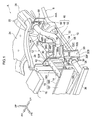
- Fig. 2 is a perspective view illustrating a schematic configuration of a front section of a car A applied with the vehicle body front section structure.
- a vehicle body B of the car A includes a pair of left and right front side members 12.
- the front side members 12 are respectively disposed with their length direction in the longitudinal direction, and are disposed side-by-side in the vehicle width direction.
- Each of the front side members 12 is joined through a crash box 14 to bumper reinforcement 16 that is configured with its length direction in the vehicle width direction. Namely, the bumper reinforcement 16 spans between front ends of the left and right crash boxes 14.
- the bumper reinforcement 16 of the present exemplary embodiment has a B-shaped cross-section profile as taken orthogonally to its length direction.
- the bumper reinforcement 16 is configured with a B-shaped cross-section profile by joining a front panel 16F to respective flanges of a rear panel 16R that is configured by a pair of upper and lower recessed portions that are open toward the front, the recessed portions being formed between three flanges, namely an upper, an intermediate, and a lower flange, so as to configure two closed cross-section portions in a row above and below each other.
- a recessed portion that opens toward the rear is configured between the upper and lower closed cross-section portions.
- beads that project out toward the rear (toward the insides of the closed cross-sections) so as to open toward the front may be formed across the vehicle width direction of the front panel 16F at portions configuring front walls of the upper and lower closed cross-sections.
- the bumper reinforcement 16 is configured with high rigidity and strength with respect to bending due to employing a structure such as in this example.
- a radiator support 18 is attached between front portions of the left and right front side members 12.
- both vehicle width direction ends of an upper member 18U and a lower member 18L that face each other from above and below are joined together by a pair of left and right side members 18S, such that the radiator support 18 is configured including a portion formed with a rectangular frame shape as viewed from the front.
- a center member 18C is provided to couple together vehicle width direction center portions of the upper member 18U and the lower member 18L.
- the side members 18S of the present exemplary embodiment each include a jutting out portion that juts out toward the vehicle width direction outside, and together with a flange 52F, described later, the jutting out portion is interposed between and fastened together with a front flange 30 and a rear flange 40, described later (see Fig. 5 ).
- a dash panel 20 that partitions an engine compartment E from a cabin C is joined to a rear end side of each of the front side members 12. More specifically, rear portions of the front side members 12 are each configured with a kick portion 12K inclined such that a rear side is positioned lower than a front side thereof. Each kick portion 12K is joined to a front face side of the dash panel 20. A rear lower end of each kick portion 12K is connected to underfloor reinforcement that is joined to the underneath of a floor panel, not illustrated in the drawings.
- a vehicle width direction central portion of the dash panel 20 is formed with a tunnel section 20T that is connected to a floor tunnel T.
- each fender apron 22 is provided at the vehicle width direction outside of each of the front side members 12.
- each fender apron 22 forms a wheel house H that accommodates a front wheel, not illustrated in the drawings, in a manner allowing the front wheel to be steered, and is also integrally formed with a suspension tower 22S.
- Each suspension tower 22S is configured to support an upper end portion of a suspension, not illustrated in the drawings, supporting the front wheels accommodated in the wheel houses H.
- a suspension member 24 that supports the suspension is attached to each front side member 12.
- the suspension member 24 is an I-shaped suspension member with length in the vehicle width direction, and both ends of the suspension member 24 in the vehicle width direction support a lower arm, not illustrated in the drawings, configuring the suspension, such that the lower arm is rotatable about an axis running along the vehicle longitudinal direction.
- the suspension member 24 is joined to the front side members 12 at plural locations separated from each other to the front and rear. Specifically, front portions of both vehicle width direction outer ends of the suspension member 24 are joined through arm members 24A to longitudinal direction intermediate portions of the front side members 12 from below. Although not illustrated in the drawings, rear portions of both vehicle width direction outer ends of the suspension member 24 are joined, either directly or indirectly, to the rear lower end portions of the kick portions 12K of the front side members 12.
- a portion at a vehicle width direction inner end and vertical direction lower end of each fender apron 22 is joined to the corresponding front side member 12.
- a portion at a vehicle width direction outer end and vertical direction upper end of each fender apron 22 is joined to an apron upper member 26, this being a framework member with length direction in the longitudinal direction.
- Each apron upper member 26 is disposed following a vehicle width direction outer end of a front upper section of the vehicle body B, and a rear end portion of each apron upper member 26 is joined to a cowl portion, not illustrated in the drawings. In other words, a rear end of the apron upper member 26 is supported by the dash panel 20 through the cowl portion.
- a front end side of each apron upper member 26 is coupled through an extension 28 to an upper end of the side member 18S (a vehicle width direction outer end portion of the upper member 18U) configuring the radiator support 18.
- the front flange 30 for joining to the crash box 14 is provided at a front end of each front side member 12.
- the front flange 30 is a member formed substantially in a hat shape opening toward the rear in plan view, and with its length running in the vertical direction.
- the front flange 30 projects out downward with respect to the front side member 12.
- a lower member 32 this being a member with length running from front to rear, couples between a lower portion of each front flange 30 and a vehicle width direction outside end portion of a front portion of the suspension member 24.
- a flange 34F provided to a rear end of a pipe member 34 with length in the longitudinal direction is joined by fastening in the longitudinal direction to a front-facing face of the lower portion of each front flange 30.
- Each pipe member 34 is joined by fastening with fasteners 39, such as nuts and bolts as illustrated in Fig. 1 , in a state in which the flange 34F formed at the rear end of the pipe member 34 is in face-to-face contact with a lower portion of a flange body 30F.
- Lower side bumper reinforcement 36 spans between front ends of the left and right pipe members 34.
- a power unit P (see Fig. 3 ), this being a drive source of the car A, is installed inside the engine compartment E.
- the power unit P is directly or indirectly supported by locations configuring the vehicle body B, such as the left and right front side members 12 and the suspension member 24.
- the power unit P is disposed between the left and right front side members.
- the relevant portions of the vehicle body front section structure 10 are basically configured with lateral symmetry, and so the following explanation focuses mainly on the structure on the left side.
- the front flange 30 described above is joined to the front end of the front side member 12.
- the front flange 30 is configured including at least the forward-facing flange body 30F, a pair of side walls 30S extending from both left and right ends of the flange body 30F toward the rear, and a bottom wall 30B connecting the flange body 30F together with lower ends of the pair of side walls 30S.
- plural weld nuts 38 are provided at a back face of the flange body 30F.
- the side wall 30S on the vehicle width direction inside of the front flange 30 is disposed either in contact with, or extremely close to, a side face 12S1, this being a vehicle width direction inside-facing inside face of the front side member 12.
- the vehicle width direction inside side wall 30S corresponds to a side wall portion.
- the rear flange 40 is provided to a rear end of the crash box 14.
- the rear flange 40 is configured with peripheral walls 40S projecting out a short distance toward the front from peripheral edges of a flange body 40F.
- bolt insertion holes are formed in the flange body 40F at positions corresponding to the weld nuts 38 of the flange body 30F.
- the crash box 14 is joined to the front end of the front side member 12 by fastening the rear flange 40 to the front flange 30 by screwing bolts 42 together with the weld nuts 38.
- the flange 52F serving as a joining plate of a coupling member 46, described later, is interposed between and fastened together with the rear flange 40 of the crash box 14 and the front flange 30 of the front side member 12.
- the four fastening positions where the weld nuts 38 and the bolts 42 are screwed together are respectively disposed so as to be on both the upper and lower sides of a center line splitting a cross-section orthogonal to the length direction of the front side member 12 into top and bottom, and on both the left and right sides of a center line splitting the cross-section into left and right.
- a forward facing plate shaped end plate 44 is joined to a front end of the apron upper member 26.
- the end plate 44 extends along a front edge of the fender apron 22 from a join portion with the apron upper member 26 toward the vehicle width direction inside, and is also joined to the front edge of the fender apron 22.
- a vehicle width direction outer end of the end plate 44 configures a rectangular plate portion 44A that is substantially square shaped as viewed from the front.
- a location where the end plate 44 is also joined to the front edge of the fender apron 22 forms a substantially arc shape as viewed from the front, and is connected to a vehicle width direction inside and a lower side end portion of the rectangular plate portion 44A.
- a structural body configured by joining together the fender apron 22, the apron upper member 26, and the end plate 44, or any one or two of these members in isolation, corresponds to a fender apron of the present invention.
- the vehicle body front section structure 10 includes the coupling member 46 that couples the front end of the apron upper member 26 to the front end of the front side member 12.
- the coupling member 46 is configured with main portions of a pipe 48, serving as a main body having a closed cross-section structure, a rear flange 50 provided to a rear end of the pipe 48, and a front side join portion 52 provided at a front end of the pipe 48.
- the rear flange 50 is joined to the front end of the apron upper member 26 by being joined by fastening to the rectangular plate portion 44A of the end plate 44 by screwing together bolts 58 and weld nuts 59.
- the coupling member 46 is joined to the apron upper member 26 through the end plate 44. Accordingly, the fastening direction of the coupling member 46 to the apron upper member 26, namely to the end plate 44, is substantially aligned with the longitudinal direction.
- the pipe 48 is, for example, formed by bending a pipe member, and is curved in the manner described below so as to couple together the front end of the apron upper member 26 and the front end of the front side member 12, these being at different positions to each other in the longitudinal direction, the vertical direction, and the vehicle width direction.
- the pipe 48 is formed such that a rear portion 48R, an intermediate portion 48C, and a front portion 48F are connected together in this sequence from the rear.
- the rear portion 48R is formed in a circular arc shape as viewed from the side, is disposed such that an upper rear end thereof is in a direction tangential to the longitudinal direction, and is joined to the rear flange 50.
- the front portion 48F is formed in a straight line shape angled such that a rear side of the front portion 48F is separated further to the vehicle width direction outside of the front side member 12 than a front side of the front portion 48F in plan view.
- a front end 48FF of the front portion 48F configures an open end opening toward the front and the vehicle width direction inside at the vehicle width direction outside of the crash box 14.
- the intermediate portion 48C is formed to connect the rear portion 48R and the front portion 48F together.
- the intermediate portion 48C is configured by a straight portion extending downward toward the front along a direction tangential to a front lower end of the rear portion 48R, and a circular arc shaped portion smoothly connecting a front lower end of the straight portion to a rear end of the front portion 48F (so as to form boundaries thereto along respective tangential directions).
- the rear portion 48R mainly has a straight line shape running along the longitudinal direction, and the intermediate portion 48C and the front portion 48F are formed in a straight line shape angled such that the rear side is separated further to the vehicle width direction outside of the front side member 12 than the front side.
- a vehicle width direction inside end portion of the front end 48FF of the front portion 48F (hidden by the flange 52F, described later, in Fig. 1 ) is positioned at (in the vicinity of) the vehicle width direction outside of the join portion between the front side member 12 and the crash box 14.
- the front portion 48F (a portion mainly hidden by the flange 52F, described later, in Fig. 4 ) configures a horizontal portion running in a substantially horizontal plane (along the length direction of the front side member 12).
- the front side join portion 52 is joined to the substantially horizontal front portion 48F.
- a portion of the main body extending rearward from the front side join portion 52 along the length direction of the front side member 12 (the horizontal direction) configures the front portion 48F, and the front portion 48F corresponds to a horizontal portion of the present invention.
- the front side join portion 52 is configured including the flange 52F that is fastened together with the rear flange 40 of the crash box 14 and the front flange 30 of the front side member 12, and a pipe-joined portion 52C that is joined to the front portion 48F of the pipe 48.
- the front side join portion 52 has a two-member configuration including a main panel 54 and a reinforcement panel 55, both of which serve as plate members.
- the flange 52F is configured by the main panel 54, is formed in a forward-facing flat plate shape, and is formed with four bolt insertion holes (not illustrated in the drawings) through which the bolts are inserted.
- Peripheral walls 54S project out a short distance toward the front from peripheral edges of the main panel 54.
- a portion of the main panel 54 at the vehicle width direction outside of the portion configuring the flange 52F is angled to follow the length direction of the front portion 48F of the pipe 48, and is formed with a recess 54N that is recessed in a semicircular shape so as to cover the rear of the front portion.
- the reinforcement panel 55 is formed with a hat shaped cross-section that encloses the pipe 48 that fits into the recess 54N. Accordingly, in the pipe-joined portion 52C, both the main panel 54 and the reinforcement panel 55 jut out along the vertical direction on both sides of the pipe 48.
- the pipe 48 and the front side join portion 52 are joined together by welding at respective portions in a state in which the front portion 48F is fitted into the recess 54N and the pipe 48 is covered by the reinforcement panel 55. More specifically, the reinforcement panel 55 and the main panel 54 are joined together by performing a long weld (either continuously or intermittently; the same applies below) along the length direction of the front portion 48F (a direction orthogonal to the cross-section illustrated in Fig. 7 ) at arc weld portions AW1 illustrated in Fig. 7 .
- the main panel 54 and the front portion 48F of the pipe 48 are joined together by performing a long weld along the length direction of the front portion 48F at arc weld portions AW2.
- the reinforcement panel 55 and the front portion 48F of the pipe 48 are also joined together by performing a long weld along the length direction of the front portion 48F at an arc weld portion AW3.
- the reinforcement panel 55 is superimposed with the main panel 54 at two locations straddling the recess 54N in the vertical direction, and the arc weld portions AW1 are configured by fillet welds (superimposed joints) along upper and lower edge portions of the reinforcement panel 55.
- the arc weld portions AW2 are formed by arc welding open ends of the recess 54N and a peripheral face of (the front portion 48F of) the pipe 48 along the length direction of the front portion 48F.
- the front side join portion 52 may be understood as a configuration in which the flange 52F is a single-member configuration of the main panel 54, and the pipe-joined portion 52C is a two-member configuration of the main panel 54 and the reinforcement panel 55.
- the rear flange 50 is joined to the end plate 44 by fastening from the front, and the flange 52F of the front side join portion 52 is fastened together with the rear flange 40 and the front flange 30 in an interposed state therebetween.
- the coupling member 46 is thereby configured to couple the front end of the apron upper member 26 and the front end of the front side member 12 together.
- the coupling member 46 of the present exemplary embodiment may be understood as a framework member supported by the front side member 12 and the apron upper member 26 in a state in which the coupling member 46 juts out toward the vehicle width direction outside with respect to the front side member 12.
- the coupling member 46 is also configured jutting out by a large amount to the vehicle width direction outside with respect to the bumper reinforcement 16.
- the coupling member 46 may accordingly be understood as being, in effect, an input location of collision load in a collision mode at the vehicle width direction outside of the front side member 12.
- a portion on the front end side of the coupling member 46 namely the front portion 48F and the intermediate portion 48C of the pipe 48, and the pipe-joined portion 52C of the front side join portion 52, are angled such that the rear side is separated further from the front side member 12 than the front side in plan view.
- the front end 48FF of the pipe 48 configuring the coupling member 46 projects out further to the front than the front end of the front side member 12.
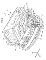
- a spacer 56 is provided to a portion of a vehicle width direction outward-facing side face 12S2 of the front side member 12 that is at the vehicle width direction inside of the coupling member 46.
- the spacer 56 is disposed at a portion positioned between the front side member 12 and the coupling member 46 in plan view.
- the spacer 56 is disposed overlapping in the vertical direction with the front side member 12 and a portion on the front end side of the coupling member 46.
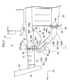
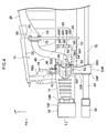
- the spacer 56 overlaps with the front portion 48F of the pipe 48 configuring the coupling member 46 in the vehicle width direction and the vertical direction as viewed from the front (as viewed along arrow X in Fig. 3 ), and overlaps with the front portion 48F of the pipe 48 configuring the coupling member 46 in the longitudinal direction and the vertical direction as viewed from the side (as viewed along arrow Y in Fig. 3 , see also Fig. 4 ).
- the spacer 56 is disposed facing the front portion 48F of the coupling member 46.
- the spacer 56 may also be understood as being disposed facing the pipe-joined portion 52C that serves as an opposing face portion of the front side join portion 52 of the coupling member 46.
- the coupling member 46 When the coupling member 46 receives load toward the rear and deforms, (a portion of the front side join portion 52 that fits together with) the front portion 48F of the pipe 48 configuring the coupling member 46 is configured to impinge on the spacer 56. A portion of the spacer 56 on which the thus deformed coupling member 46 impinges configures an angled face 56C that is angled so as to face toward the vehicle width direction outside and the front in plan view.
- the spacer 56 is joined to a portion of the front side member 12 positioned slightly in front of the power unit P, and projects out from the side face 12S2 of the front side member 12 toward the vehicle width direction outside at this portion.
- the joining structure of the spacer 56 to the front side member 12 employs fastening with fasteners including bolts 60 at flanges 56F jutting out to the front and rear of the spacer 56.
- the spacer 56 is configured to function as a load transmission member that transmits load from the coupling member 46 to the front side member 12 when the coupling member 46 impinges on the spacer 56 as described above. This load transmission promotes folding of the front side member 12 in the vicinity of the power unit P, as will be explained later under Operation of the present exemplary embodiment.
- the spacer 56 may be configured employing a lightweight (low density) material such as aluminum (or an alloy thereof) or resin, as long as it functions as a load transmission member as described above.
- a lightweight (low density) material such as aluminum (or an alloy thereof) or resin
- a load Fy toward the vehicle width direction inside is generated in the front portion 48F, where the pipe 48 of the coupling member 46 is angled in plan view.
- the load Fy acts as a force in a direction to move the car A and the barrier Br apart in the vehicle width direction. Namely, the car A and the barrier Br are displaced in the vehicle width direction due to the barrier Br impinging on the coupling member 46, promoting the car A and the barrier Br to slide past one another. The barrier Br is thereby suppressed from intruding into the car A.
- the front side member 12 pushes the power unit P toward the vehicle width direction inside due to this folding. Lateral force (force due to inertia) input to the power unit P, this being (one) section where mass is concentrated in the car A, moves the car A itself toward a collision opposite side (away from the barrier Br in the vehicle width direction). The car A and the barrier Br are thus further promoted to slide past one another, and localized deformation of a collision side end section of the vehicle body B is prevented or effectively suppressed.
- a portion on the front end side of the coupling member 46 namely the front portion 48F and the intermediate portion 48C of the pipe 48, and the pipe-joined portion 52C of the front side join portion 52, is angled such that a rear side is separated further from the front side member 12 than a front side in plan view.
- the angled portion converts a portion of the collision load into the load Fy toward the collision opposite side.
- the coupling member 46 accordingly promotes displacement in the vehicle width direction with respect to the barrier Br, namely promotes sliding past the barrier Br described above.
- the portion on the front end side of the coupling member 46 is angled as described above, such that the coupling route between the front side member 12 and the end plate 44 is shorter than in an L-shaped coupling member with a portion jutting out along the vehicle width direction and an extension portion extending from the jutting out portion toward the rear in plan view.
- the coupling member 46 accordingly acts to pull the front end of the front side member 12 toward the vehicle width direction outside with less play (free movement distance) than the coupling member of the above comparative example.
- the coupling member 46 accordingly works together with the spacer 56 to greatly promote folding of the front side member 12.
- the front flange 30 that is joined to the front side join portion 52 of the coupling member 46 includes the side walls 30S.
- the side walls 30S function to push the front end of the front side member 12 in the vehicle width direction when the front end of the front side member 12 is pulled toward the vehicle width direction outside due to the barrier Br pushing the coupling member 46 toward the rear. Accordingly, when the front end of the front side member 12 is being pulled toward the vehicle width direction outside, there is no reliance on shear of the bolts 42 alone, as there would be in a comparative example not including the side walls 30S. Accordingly, in the vehicle body front section structure 10, force to pull the front end of the front side member 12 toward the vehicle width direction outside can efficiently be caused to act in a small overlap collision.
- the weld nuts 38 and the bolts 42 that fasten the flange 52F of the coupling member together with the front flange 30 of the front side member 12 and the like include those positioned further to the vehicle width direction inside than a center line dividing the front side member 12 into left and right. Accordingly, in a small overlap collision, the (entire cross-section of the) entire front end of the front side member 12 is pulled toward the vehicle width direction outside, in contrast to in a configuration in which the flange 52F is only fastened together with the front flange 30 at the vehicle width direction outside of the center line. Moreover, in the coupling member 46 described above, the flange 52F is fastened together with the front flange 30 on both vehicle width direction sides.
- a concentration of load (stress) at a specific join location out of plural join portions that are fastened together can accordingly be better suppressed than in a configuration in which the flange 52F is only fastened together with the front flange 30 on one side of the center line.
- the front end of the front side member 12 is efficiently pulled toward the vehicle width direction outside in a small overlap collision, contributing to folding of the front side member 12 at an appropriate location and an appropriate timing.
- the front end 48FF of the pipe 48 configuring the coupling member 46 projects out further to the front than the front end of the front side member 12. Accordingly, the coupling member 46 is able to start pulling the front end of the front side member 12 toward the vehicle width direction outside after the crash box 14 has been compressed, and before the front side member 12 is compressed by the collision load.
- the front side member 12 can accordingly be made to fold stably toward the vehicle width direction inside (the folding direction of the front side member 12 is stabilized).
- the front side join portion 52 that is joined to the pipe 48 has the two-member configuration of the main panel 54 and the reinforcement panel 55. This enables more arc welding portions with the pipe 48 than in a comparative example employing a front flange configured by a single member. This thereby enables the weld between the pipe 48 and the front side join portion 52 to be prevented or thoroughly suppressed from coming apart in a small overlap collision, and enables the coupling member 46 to efficiently pull the front end of the front side member 12 toward the vehicle width direction outside.
- the coupling member 46 the flange 52F of the front side join portion 52 is joined to the front end of the front side member 12 in a state interposed between the front flange 30 of the front side member 12 and the rear flange 40 of the crash box 14. This thereby enables the coupling member 46 to be provided to counter small overlap collisions, while preventing or suppressing any detriment to energy absorption characteristics during a collision (collision performance in frontal collisions) due to the front side member 12 and the like in the vehicle body front section structure 10.
- the vehicle body front section structure 10 enables deformation of the vehicle body in a small overlap collision to be suppressed using the coupling member 46 that couples together the front side member 12 and the end plate 44, while preventing or suppressing any detriment to collision performance due to the front side member 12.
- the vehicle body front section structure 10 enables the front side member 12 and the crash box 14 to be made common to vehicles in which the coupling member 46 is not provided (such as vehicles that have a different structure for countering small overlap collisions), while suppressing any detriment to collision performance in frontal collisions. Namely, a configuration in which the coupling member 46 is provided to suppress deformation of the vehicle body in a small overlap collision can be made common to a vehicle body structure of a vehicle not provided with the coupling member 46.
- the rear flange 50 on the rear end side of the coupling member 46 is fastened to the apron upper member 26 using the bolts 58 and the weld nuts 59, and the front side join portion 52 on the front end side is fastened together with the front flanges 30, 40 using the bolts 42 and the weld nuts 38.
- This thereby facilitates achieving a structure common to vehicles not provided with the coupling member 46, or provided with structures other than the coupling member 46, compared to a comparative example in which, for example, one or both of the front and rear ends of a coupling member are joined to the vehicle body B by welding or the like.
- the coupling member 46 is joined to the end plate 44 by fastening along the longitudinal direction using the bolts 58 and the weld nuts 59.
- collision load is borne by the shear of the bolts.
- the fastening direction to the end plate 44 is the longitudinal direction, the collision load can be borne as axial force by the coupling member 46 (the rear portion 48R of the pipe 48).
- the coupling member 46 can accordingly efficiently receive load from the barrier Bumper reinforcement, without relying on the shear strength of the bolts 58.
- the spacer 56 is provided between the front side member 12 and the coupling member 46, and overlaps with the front side member 12 and the coupling member 46 in the vertical direction. Accordingly, when the coupling member 46 that has been deformed or displaced toward the rear due to collision load in a small overlap collision impinges on the spacer 56, the spacer 56 pushes the front side member 12 toward the vehicle width direction inside as described above. This operation, together with the operation of the coupling member 46 to pull the front end of the front side member 12 toward the vehicle width direction outside, promotes folding of the front side member 12 at the side of the power unit, and promotes vehicle width direction displacement between the car A and the barrier Br.
- the spacer 56 is provided at the vehicle width direction outside facing side face 12S2 of the front side member 12. Accordingly, a specific location of the front side member 12 (the location where the spacer 56 is installed) is pushed toward the vehicle width direction inside by the spacer 56 in a small overlap collision. This thereby enables the front side member 12 to be folded at an appropriate location in a small overlap collision.
- the front portion 48F of the pipe 48 of the coupling member 46 extends substantially horizontally from the front side join portion 52 toward the rear as viewed from the side.
- the front portion 48H is accordingly suppressed from being displaced or deformed in the vertical direction by rearward load from the barrier Br, and is displaced or deformed along a substantially horizontal plane. Load from the front portion 48H is transmitted by the spacer 56 as force to push the front side member 12 toward the vehicle width direction inside.
- Component force in the vertical direction can accordingly be suppressed when transmitting this load, thereby improving load transmission efficiency from the coupling member 46, through the spacer 56, and into the front side member 12 compared to a configuration in which load is transmitted to the spacer from a coupling member that is at an incline as viewed from the side.
- Folding of the front side member 12 is accordingly promoted, and moreover, load can be efficiently transmitted to the power unit P after the front side member 12 has folded, thus promoting vehicle width direction movement of the car A away from the barrier Br.
- the pipe-joined portion 52C of the front side join portion 52 of the coupling member 46 juts out in the vertical direction with respect to the front portion 48F, and faces the spacer 56. Load from the barrier Br is accordingly also transmitted through the spacer 56 to the front side member 12 through the pipe-joined portion 52C. This thereby enables collision load to be efficiently transmitted to the front side member 12 through the pipe-joined portion 52C and the spacer 56 over a wider vertical range than in a configuration in which the join portion does not jut out to the top and bottom of the front portion 48F of the pipe 48.
- Fig. 9 is a perspective view of the vehicle body front section structure 65, corresponding to Fig. 2 .
- Fig. 10 is a perspective view of the vehicle body front section structure 65, corresponding to Fig. 3 .
- Fig. 11 is a perspective view of the vehicle body front section structure 65, corresponding to Fig. 4 .
- the vehicle body front section structure 65 differs from the vehicle body front section structure 10 in the provision of a support member 62.
- an apex portion 56T where the spacer 56 juts out furthest in the vehicle width direction is positioned substantially at the longitudinal direction center of the spacer 56.
- the spacer 56 is formed with a supported face 56S, this being an angled face angled so as to face toward the vehicle width direction outside and the rear in plan view, at the rear of the apex portion 56T.
- the support member 62 is provided projecting out toward the spacer 56 side at the front portion 48F (which may encompass a portion of the intermediate portion 48C positioned in the vicinity of a boundary therewith), this being the angled portion of the pipe 48 configuring the coupling member 46.
- the support member 62 has a narrow width at a leading end 62P side positioned further to the spacer 56 side than a base end 62B on the side joined to the pipe 48.
- the support member 62 has a wedge shaped outer profile in plan view.
- a structure for joining the support member 62 to the pipe 48 employs fastening using fastenings including bolts 64.
- the support member 62 projects out from the pipe 48 to the spacer 56 side such that the leading end 62P faces the supported face 56S side of the spacer 56, and corresponds to a projection portion of the present invention. Together with the coupling member 46, the support member 62 is disposed in a state separated from the spacer 56. Namely, the support member 62 is not restrained by the spacer 56. In the present exemplary embodiment, the leading end 62P of the support member 62 is positioned further to the vehicle width direction outside than the apex portion 56T of the spacer 56. Namely, the entire support member 62 is disposed offset to the vehicle width direction outside with respect to the spacer 56 across a gap G, illustrated in Fig. 10 .
- the support member 62 provided to the coupling member 46 swings around to the rear of the supported face 56S of the spacer 56 while undergoing displacement toward the rear together with the coupling member 46. Namely, the support member 62 swings around to the vicinity of the rear side of the spacer 56 accompanying rotation about the front end side of the coupling member 46. Accordingly, as illustrated in Fig. 12D , the spacer 56 transmits load from the coupling member 46 to the front side member 12 while the supported face 56S is supported from the rear by the support member 62.
- the spacer 56 is subjected to shear load between the spacer 56 and the front side member 12 (the side face 12S2) due to the load from the coupling member 46.
- this shear load is supported by the support member 62, such that positional displacement of the spacer 56 with respect to the front side member 12 in the longitudinal direction, and decoupling of the spacer 56 from the front side member 12, is prevented or effectively suppressed.
- the support member 62 provided to the coupling member 46 is displaced toward the rear together with the coupling member 46 (spacer 56). Accordingly, positional displacement and decoupling of the spacer 56 with respect to the front side member 12 are prevented or effectively suppressed due to obstructing movement of the spacer 56 toward the rear.
- the support member 62 and the coupling member 46 are disposed at a separation to the spacer 56. Accordingly, the movement of the spacer 56 is prevented or effectively suppressed from being restrained or impeded by the support member 62 and the coupling member 46 in collision modes other than a small overlap collision, such as a full overlap frontal collision. Namely, in a collision mode other than a small overlap collision, restraint of or interference with the behavior of the front side member 12 by the support member 62 and the coupling member 46 is prevented or effectively suppressed due to the spacer 56.
- the support member 62 is accordingly provided so as not to be detrimental to collision performance in collision modes other than a small overlap collision, and also enables improved collision performance in a small overlap collision.
- the entire support member 62 is offset to the vehicle width direction outside with respect to the spacer 56. The support member 62 therefore does not impinge during simple rearward movement of the spacer 56, enabling any detriment to collision performance to be kept small in collision modes other than a small overlap collision.
- a vehicle body front section structure 70 of a third exemplary embodiment of the present invention with reference to Fig. 13 and Fig. 14 .
- components and portions that are basically the same as those of the first or the second exemplary embodiment are allocated the same reference numerals as in the first or the second exemplary embodiment, and explanation and illustration thereof is omitted as appropriate.
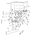
- Fig. 13 is a plan view corresponding to Fig. 10 , and illustrates relevant portions of the vehicle body front section structure 70.
- a coupling member 72 configuring the vehicle body front section structure 70 is configured with main portions of a pipe 74 serving as a main body, the front side join portion 52, and the rear flange 50.
- the pipe 74 differs from the pipe 48 in the point that it is formed with a projection portion 74P, serving as a support member, by bending the pipe member from which it is made. Specific explanation follows thereof.
- the pipe 74 includes a rear portion 74R formed similarly to the rear portion 48R, and a front portion 74F that is configured similarly to the front portion 48F at least at a location joined to the pipe-joined portion 52C of the front side join portion 52.
- the pipe 74 further includes an intermediate portion 74C connecting between the rear portion 74R and the front portion 74F.
- the projection portion 74P is formed to a portion including part of the intermediate portion 74C on the front portion 74F side, or including a rear end side of the front portion 74F and part of the intermediate portion 74C on the front portion 74F side.
- the projection portion 74P projects out to the spacer 56 side of a hypothetical line IL connecting between a boundary of the intermediate portion 74C with the rear portion 74R, and the front portion 74F, in plan view.
- the projection portion 74P is configured projecting out to the spacer 56 side of an angled portion formed by the front portion 74F and the intermediate portion 74C.
- the projection portion 74P is an inflected portion (bent portion) formed in a substantially V shape opening forward and toward the vehicle width direction outside in plan view by bending at three bending locations 74B1, 74B2, and 74B3.
- the projection portion 74P overlaps with the spacer 56 in the vertical direction at least in a region from the boundary with the front portion 74F to an apex portion 74PP at the bend of the V shape.
- the position of the apex portion 74PP with respect to the spacer 56 is similar to the position of the leading end 62P of the support member 62.
- the projection portion 74P is accordingly disposed at a separation to the spacer 56, and the entire projection portion 74P is disposed offset to the vehicle width direction outside with respect to the spacer 56.
- the projection portion 74P configured as described above swings around to the rear of the supported face 56S of the spacer 56 (see Fig. 14 ).
- the projection portion 74P contacts or becomes extremely close to the supported face 56S in this swung around state.
- the projection portion 74P of the third exemplary embodiment As illustrated in Fig. 14 , when the coupling member 72 deforms until it impinges on the spacer 56, the projection portion 74P that is integrally formed to the coupling member 72 swings around to the rear of the supported face 56S of the spacer 56. Namely, the projection portion 74P swings around to the vicinity of the rear side of the spacer 56 accompanying rotation of the coupling member 72 about its front end side. The spacer 56 accordingly transmits load from the coupling member 72 to the front side member 12 while the supported face 56S is supported from the rear by the projection portion 74P.
- the vehicle body front section structure 70 according to the third exemplary embodiment thereby exhibits similar operation to the vehicle body front section structure 10 according to the first exemplary embodiment, and can accordingly obtain similar operation to the vehicle body front section structure 10 according to the first exemplary embodiment.
- Operation of the coupling member 46, and operation and advantageous effects of the spacer 56 are also basically the same as those in the vehicle body front section structure 10, enabling similar operation to the vehicle body front section structure 10 to be obtained.
- the projection portion 74P is integrally formed by bending the pipe 74 configuring the coupling member 72, thereby enabling the projection portion 74P, serving as a support member, to be provided without entailing an increase in the number of components.
- a vehicle body front section structure 80 according to a fourth exemplary embodiment of the present invention, with reference to Fig. 15 .
- components and portions that are basically the same as those of the first or the second exemplary embodiment are allocated the same reference numerals as in the first or the second exemplary embodiment, and explanation and illustration thereof is omitted as appropriate.
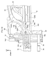
- Fig. 15 is a plan view corresponding to Fig. 10 , illustrating relevant portions of the vehicle body front section structure 80. As illustrated in Fig. 15 , the vehicle body front section structure 80 differs from the first exemplary embodiment in the point that a support member 82 is provided in place of the support member 62. Specific explanation follows thereof.
- the support member 82 is formed as a substantially L shaped member in plan view. More specifically, the support member 82 is configured by a support plate 82S that stands out from an end portion of a base plate 82B. In the present exemplary embodiment, the support member 82 is formed in an L shape as described above by bending (pressing) sheet metal such as a steel sheet or an aluminum sheet.
- the base plate 82B is joined to the front portion 48F (encompassing a portion in the vicinity of the boundary between the front portion 48F and the intermediate portion 48C) of the pipe 48, and the support plate 82S is superimposed with the supported face 56S of the spacer 56 and joined to the spacer 56.
- the joining structures employ fastening using fasteners including bolts 84.
- the support member 82 of the fourth exemplary embodiment couples the coupling member 46 and the spacer 56 together.
- the spacer 56 accordingly transmits load from the coupling member 46 to the front side member 12 while the supported face 56S is supported from the rear by the support member 82.
- the vehicle body front section structure 80 according to the fourth exemplary embodiment accordingly exhibits similar operation and advantageous effects to the vehicle body front section structure 10 according to the first exemplary embodiment, with the exception of operation due to disposing the support member 62 at a separation to the spacer 56. Due to sharing common operation with the vehicle body front section structure 10, similar advantageous effects can also be obtained to those of the vehicle body front section structure 10. Operation of the coupling member 46, and operation and advantageous effects of the spacer 56, are also basically the same as those of the vehicle body front section structure 10, thereby enabling similar operation to the vehicle body front section structure 10 to be obtained.
- a coupling member may be employed with a rear end joined to the apron upper member 26 or the fender apron 22.
- a front side join portion 52 includes the main panel 54 and the reinforcement panel 55; however, the present invention is not limited thereto.
- a front side join portion may be employed with a structure in which the pipe 48 (main body) is enclosed by bending a single panel (a structure in which a single panel configures a pair of plate portions).
- a front side join portion may be employed that is only joined to the pipe 48 (main body) from one side.
- a front side join portion configured from three or more panels may be employed. Namely, it is sufficient that the front side join portion is joined to the pipe 48 (main body) with the necessary strength for the load received in a small overlap collision.
- the pipe 48 of the coupling member 46 includes the front portion 48F serving as a horizontal portion; however, the present invention is not limited thereto.
- configuration may be made with a coupling member in which a front portion, namely a portion overlapping with the spacer 56 in the vertical direction, includes a pipe that is angled or curved with respect to the length direction of the front side member 12 as viewed from the side.
- the spacer 56 provided to the side face 12S2 of the front side member 12 is fastened thereto; however, the present invention is not limited thereto.
- the spacer 56 may be joined to the front side member 12 by joining structures using welding, brazing, bonding, or the like.
- the present invention in which the spacer is supported from the rear by a support member (projection portion) in a small overlap collision, enables the joining structure to be simplified.
- Fig. 16 is a perspective view illustrating configuration of relevant portions of a vehicle body front section structure 100 according to a fifth exemplary embodiment of the present invention.
- Fig. 17 is a plan view illustrating the vehicle body front section structure 100
- Fig. 18 is a side view illustrating the vehicle body front section structure 100.
- the vehicle body front section structure 100 includes a coupling member 102 with a rectangular closed cross-section in place of the coupling member 46 including the pipe 48 with a circular closed cross-section.
- the vehicle body front section structure 100 moreover includes a spacer (projection member) 104 joined to the coupling member 102 in place of the spacer 56 disposed at a separation to the coupling member 46. Specific explanation follows thereof.
- the coupling member 102 extends out integrally from a front end portion of the apron upper member 26, and a front end portion of the coupling member 102 is fixed to a front portion of the front side member 12.
- the coupling member 102 is formed with a rear portion 102R, an intermediate portion 102M, and a front portion 102F connected in sequence from the rear.
- the rear portion 102R of the coupling member 102 extends downward and toward the front from the front end portion of the apron upper member 26.
- the rear portion 102R of the present exemplary embodiment is inclined at an angle closer to the vertical than to the horizontal, as illustrated in Fig. 18 .
- the intermediate portion 102M extends downward and toward the front from a front end portion of the rear portion 102R.
- the intermediate portion 102M has an angle of inclination closer to the horizontal than the rear portion 102R as viewed from the side, and is set at an angle of inclination of approximately 45° in the present exemplary embodiment.
- the intermediate portion 102M is angled such that in plan view, a front side is closer to the front side member 12 than a rear side in the vehicle width direction.
- the front portion 102F of the coupling member 102 is disposed at the same height as the front side member 12 (overlapping in the vertical direction), and is positioned at the vehicle width direction outside of a front portion of the front side member 12.
- a front end side of the front portion 102F extends toward the vehicle width direction inside, and reaches between the front side member 12 and the crash box 14.
- a vehicle width direction outside face of the coupling member 102 (in particular of the front portion 102F and the intermediate portion 102M) configures a curved face 102C that curves such that a rear side faces more toward the vehicle width direction outside than a front side.
- the outer panel 108 is configured with a hat shaped cross-section opening in a substantially rear-facing direction, and the inner panel 110 has a flat plate shape joined to the upper and lower flanges of the outer panel 108.
- a flat plate shaped flange 110F extends out toward the vehicle width direction inside from a vehicle width direction inside end portion of the front portion 102F of the inner panel 110.
- a flange 108F extending out from a vehicle width direction inside end portion of the outer panel 108 is joined to a portion on the vehicle width direction outer end side of the flange 110F from the front.
- the plate thickness direction of the flange 110F runs in the longitudinal direction, and an vertical direction intermediate portion of the flange 110F is cut away from the vehicle width direction inside.
- the flange 110F is interposed between the flange body 30F of the front flange 30 provided to the front side member 12 and the flange body 40F of the rear flange 40 provided to the crash box 14.
- the flange 110F is joined between the flange body 30F and the flange body 40F by fastening together at four fastening locations by screwing together the weld nuts 38 and the bolts 42.
- the flange 110F of the coupling member 102 corresponds to a joining plate.
- a front end of the coupling member 102 described above is positioned further to the front than the front end of the front side member 12.
- the outer panel 108 includes a projection portion 102P projecting out to the front of the flange 108F.
- a front end of the projection portion 102P is positioned further to the front than the front end of the front side member 12.
- the vehicle body front section structure 100 includes the spacer 104 that is joined to the front side member 12 and the coupling member 102 respectively.
- the spacer 104 is, for example, formed in a vertically flattened hollow triangular column shape by joining together plural members formed from sheet metal material.
- the spacer 104 projects out from the front portion of the front side member 12 toward the vehicle width direction outside.
- the spacer 104 is, for example, joined to the side face 12S2, this being a vehicle width direction outside wall portion of the front side member 12, by means such as welding or the like.
- the spacer 104 includes a load transmission portion 106 angled such that a rear side is further toward the vehicle width direction inside than a front side.
- the load transmission portion 106 configures a vehicle width direction outside (rear side) wall of the spacer 104.
- the spacer 104 is configured from main portions of an inner panel 112 that is joined to the front side member 12, and an outer panel 114 that is joined to the inner panel 112 and forms a closed cross-section with the inner panel 112. As illustrated in Fig.
- the outer panel 114 extends from a high rigidity portion (a location installed with a bulkhead 116), described later, of the coupling member 102, and reaches as far as the location of a join between a rear portion of the spacer 104 and the side face 12S2 of the front side member 12.
- the outer panel 114 is configured as a portion of the spacer 104 with high rigidity with respect to rearward load by, for example, configuring the outer panel 114 from a material with greater thickness, or with higher tensile strength, than the inner panel 112. Accordingly, in the present exemplary embodiment, the load transmission portion 106 is configured mainly at the outer panel 114.
- a front side join portion 106A is provided at a front end portion of the load transmission portion 106.
- the front side join portion 106A is bent so as to follow a back face 102B of the front portion 102F of the coupling member 102 (a rear wall portion 116R of the bulkhead 116, described later), and is joined to the back face 102B by means such as welding or bolt fastening.
- a rear side join portion 106B is provided at a rear end portion of the load transmission portion 106.
- the rear side join portion 106B is bent so as to follow the side face 12S2 of the front side member 12, and is joined to the side face 12S2 by means such as welding or bolt fastening.
- the bulkhead 116 serving as a reinforcement member, is provided inside the cross-section of the front portion 102F of the coupling member 102.
- the bulkhead 116 is formed in a hat shape, opening toward the rear in plan view.
- the bulkhead 116 includes the rear wall portion 116R forming the bottom of the hat shape, a pair of arms 116A extending from both vehicle width direction ends of the rear wall portion 116R toward the front, and a pair of left and right front flanges 116F extending from front ends of both arms so as to head away from each other in the vehicle width direction.
- the rear wall portion 116R is joined to an inner face (front face) of a portion of the inner panel 110 forming the back face 102B of the coupling member 102 by means such as welding.
- the pair of front flanges 116F are joined to an inner face (rear face) of a portion of the outer panel 108 configuring the front portion 102F by means such as welding. More specifically, the front flange 116F on the vehicle width direction inside is joined to the inner face at a portion of the outer panel 108 configuring the projection portion 102P. The front flange 116F on the vehicle width direction outside is joined to the inner face at a portion of the outer panel 108 configuring a front portion of the curved face 102C.
- the vehicle body front section structure 100 is thus formed with a path along which rearward load input to a front end portion of the coupling member 102 passes through the bulkhead 116 and the load transmission portion 106 of the spacer 104, and is transmitted into the front side member 12.
- the bulkhead 116 configures a reinforcement structure at a portion where the front portion 102F of the coupling member 102 transmits load to the spacer 104.
- the bulkhead 116 forms the high rigidity portion at the front portion 102F of the coupling member 102.
- the bulkhead 116 may be understood as a portion of the spacer 104 (a front side extension portion of the load transmission portion 106) that transmits load input to the projection portion 102P to the front side member 12, and is independent of the coupling member 102 that transmits load to the apron upper member 26.
- the front portion 102F of the coupling member 102, the bulkhead 116, and the spacer 104 may also be collectively understood as a member (gusset) for transmitting rearward load input at the vehicle width direction outside of the front side member 12 to the front side member 12.
- vehicle body front section structure 100 has basically the same configuration as in the vehicle body front section structure 10 according to the first exemplary embodiment. Accordingly, the vehicle body front section structure 100 enables basically the same advantageous effects to be obtained from the same operation as in the vehicle body front section structure 10.
- the load transmission portion 106 of the spacer 104 is joined to the back face 102B of the coupling member 102.
- Load can accordingly be transmitted from the barrier Br to a side portion of the front side member 12 through the coupling member 102 (bulkhead 116) and the spacer 104 from before the coupling member 102 starts to deform.
- the spacer 104 since the spacer 104 includes the load transmission portion 106 as described above, when collision load is input to the projection portion 102P of the coupling member 102 from the front, the load can be efficiently transmitted through the load transmission portion 106 to the front side member 12.
- a fold toward the vehicle width direction inside can be induced in the front side member 12 since stress can be concentrated in the front side member 12 in the vicinity of a rear end of the load transmission portion 106 (at the side of the power unit P).
- the projection portion 102P of the coupling member 102 is positioned further toward the front than the front end of the front side member 12, and so collision load accordingly acts on the coupling member 102 before acting on the front side member 12 after the crash box 14 has been compressed.
- the projection portion 102P of the coupling member 102 is positioned further to the vehicle width direction outside than the front side member 12, and so the collision load causes moment acting in a direction to fold the front side member toward the vehicle width direction inside. Folding of the front side member 12 toward the vehicle width direction inside is accordingly promoted.
- a stable displacement mode of the car A with respect to the barrier Br in the vehicle width direction can accordingly be achieved in a short time following the start of a small overlap collision, and this displacement can be further promoted.
- the coupling member 102 and the load transmission portion 106 can be prevented from unintentionally moving apart from each other due to collision load since the front end portion of the load transmission portion 106 of the spacer 104 is joined to the back face 102B of the coupling member 102 (the rear wall portion 116R of the bulkhead 116).
- the spacer 104 and the coupling member 102 are not joined together, there is concern of noise being caused by unintended interference between the coupling member and the load transmission portion 106 due to vibration of the vehicle during normal travel.
- the front end portion of the load transmission portion 106 of the spacer 104 is joined to the back face 102B of the coupling member 102 (the rear wall portion 116R of the bulkhead 116) as described above.
- the coupling member and the load transmission portion 106 due to vibration of the vehicle during normal travel, enabling the occurrence of noise caused by such interference to be prevented.
- the spacer 104 is formed in a triangular shape in plan view; however, the present invention is not limited thereto, and the shape settings of the projection member may be modified as appropriate.
- the projection member may be formed in a trapezoid or semicircle protruding toward the vehicle width direction outside in plan view.
- the crash box 14, serving as a shock absorbing section is fixed to the front side member 12 of the front side member 12; however, the present invention is not limited thereto, and a shock absorbing section may be provided integrally to a front portion of a front side member. In such cases, a front end portion of the coupling member is fixed to a portion of the front side member further to the rear side than the shock absorbing section.
- the bulkhead 116 is attached inside the cross-section of the front portion 102F of the hollow shaped 102 as a reinforcement member, thereby reinforcing the front portion 102F; however, the present invention is not limited thereto, and configuration may be made without a reinforcement member.
- a front portion of the coupling member may be formed thicker (the plate thickness of the material may be set thicker) than at other locations of the coupling member (at least a location adjacent to the front portion of the coupling member), thereby reinforcing the front portion of the coupling member.
- the front portion of the coupling member is preferably configured with higher rigidity at least with respect to load in the longitudinal direction, configuration may be made in which one or plural beads extending in the longitudinal direction, for example, are formed to a front portion of the coupling member.
- the vehicle width direction outside face of the front portion 102F of the coupling member 102 configures the curved face 102C that curves such that the rear side is positioned further to the vehicle width direction outside than the front side.
- the present invention is not limited thereto, and configuration may be made in which the vehicle width direction outside face of the front portion of the coupling member runs along the longitudinal direction, or is angled so as to face more toward the vehicle width direction outside on progression toward the rear side.
- the vehicle body front section structure 10 includes the coupling member 46, 102, and the spacer 56, 104 on both sides in the vehicle width direction; however, the present invention is not limited thereto.
- configuration may be made in which the coupling member 46, 102, and the spacer 56, 104 are provided on only one side in the vehicle width direction.
- a vehicle-mounted component may, for example, double as a spacer, or another structure may be employed to counter small overlap collisions.
- front flange 30 extends downward and supports the rear end of the pipe member 34 and the front end of the lower member 32.
- the present invention is not limited thereto.
- the front flange 30 includes a pair of side walls including the vehicle width direction inside side wall 30S; however, the present invention is not limited thereto. Configuration may be made in which the front flange 30 or an equivalent front flange is not provided with one or both of the pair of side walls.
Landscapes
- Engineering & Computer Science (AREA)
- Mechanical Engineering (AREA)
- General Engineering & Computer Science (AREA)
- Chemical & Material Sciences (AREA)
- Combustion & Propulsion (AREA)
- Transportation (AREA)
- Body Structure For Vehicles (AREA)
Abstract
Description
- The present invention relates to a vehicle body front section structure.
- Structures are known in which a coupling member is attached to a front end portion of apron reinforcement, and a face portion attached to a front end of the coupling member is interposed between and fastened together with a front side frame and a crash can (for example, see Japanese Patent Application Laid-Open (JP-A) No.
2005-231435 - In the above configuration, a load transmission path is formed to transmit load input to the face portion through the coupling member to the apron reinforcement in a small overlap collision. However, configurations which load is simply transmitted toward the vehicle rear leave room for improvement from the perspective of suppressing cabin deformation in a small overlap collision.
- An object of the present invention is to obtain a vehicle body front section structure capable of suppressing deformation of a vehicle body in a small overlap collision.
- A vehicle body front section structure according to a first aspect of the present invention includes: a front side member, with a crash box attached to a vehicle longitudinal direction front side; a coupling member that is interposed between and joined to the crash box and the front side member at a vehicle longitudinal direction front side, and that is joined to a fender apron section at a vehicle longitudinal direction rear side; and a spacer that is disposed overlapping with the front side member and the coupling member in a vehicle vertical direction at a portion positioned between the front side member and the coupling member in plan view.
- According to the above aspect, collision load is input to the coupling member in, for example, a frontal collision mode in which load is input at the vehicle width direction outside of the front side member (referred to below as a "small overlap collision"). When the coupling member undergoes deformation or displacement under this load, a front end portion of the front side member is pulled toward the vehicle width direction outside since a front end side of the coupling member is interposed between and joined to the crash box and the front side member. Moreover, the front side member is pushed toward the vehicle width direction inside by the spacer positioned between the coupling member and the front side member accompanying the deformation or displacement of the coupling member described above. The front side member accordingly folds, and the vehicle and its collision counterpart are displaced in the vehicle width direction, thereby suppressing the collision counterpart from intruding into the vehicle body of the vehicle.
- The vehicle body front section structure of the above aspect can accordingly suppress deformation of the vehicle body in a small overlap collision.
- In the above aspect, configuration may be made wherein the spacer is provided at a vehicle width direction outside side portion of the front side member.
- According to the above aspect, the spacer is provided to the front side member, such that a specific location of the front side member (the installation location) is pushed toward the vehicle width direction inside by the spacer in a small overlap collision. The front side member can accordingly be folded at an appropriate location in a small overlap collision.
- In the above aspect, configuration may be made wherein the coupling member includes a horizontal portion extending along the length direction of the front side member from a portion interposed between the crash box and the front side member toward the vehicle longitudinal direction rear as viewed from the side so as to overlap with the front side member and the spacer in the vehicle vertical direction.
- According to the above aspect, the horizontal portion of the coupling member extends from the portion of the coupling member interposed between the crash box and the front side member toward the rear, namely, substantially horizontally. The spacer transmits load from the horizontal portion as force to push the front side member toward the vehicle width direction inside. Since the horizontal portion extends substantially in the horizontal direction as described above, when collision load is transmitted to the spacer, namely to the front side member, component force is suppressed from arising in the vehicle vertical direction. This thereby enables collision load to be efficiently transmitted to the front side member.
- In the above aspect, configuration may be made wherein the coupling member is configured including a main body extending from the fender apron section toward a vehicle longitudinal direction front side portion of the front side member, and a joining plate that is joined to a vehicle longitudinal direction front side of the main body, and is interposed between and joined to the crash box and the front side member; and an opposing face portion is formed at a location of the joining plate that is joined to the main body, such that the opposing face portion juts out in the vehicle vertical direction with respect to the main body and opposes the spacer while overlapping with the spacer in the vehicle vertical direction.
- According to the above aspect, the opposing face portion that juts out in the vehicle vertical direction with respect to the main body at the joining plate opposes the spacer, thereby enabling load to be transmitted through the spacer to the front side member over a wider range in the vehicle vertical direction. Namely, collision load can be efficiently transmitted to the front side member.
- In the above aspect, configuration may be made wherein: the coupling member is configured including a main body extending from the fender apron section toward a vehicle longitudinal direction front side portion of the front side member, and a joining plate that is joined to a vehicle longitudinal direction front side of the main body, and is interposed between and joined to the crash box and the front side member; a horizontal portion, extending along the length direction of the front side member from a portion interposed between the crash box and the front side member toward the vehicle longitudinal direction rear as viewed from the side so as to overlap with the front side member and the spacer in the vehicle vertical direction, is configured including a vehicle longitudinal direction front side portion of the main body; an opposing face portion is formed to a location of the joining plate that is joined to the main body, such that the opposing face portion juts out in the vehicle vertical direction with respect to the main body and opposes the spacer while overlapping with the spacer in the vehicle vertical direction; and the joining plate includes a pair of plate portions that sandwich the horizontal portion, and the pair of plate portions are respectively joined to the horizontal portion by arc welding.
- According to the above aspect, the pair of plate portions that sandwich the horizontal portion of the main body are respectively joined to the horizontal portion by arc welding, thus firmly joining the joining plate and the main body together. Accordingly, the action of the coupling member to pull the front end side of the front side member toward the vehicle width direction outside is effectively exhibited in a small overlap collision.
- In the above aspect, configuration may be made wherein the spacer projects out to the vehicle width direction outside of the front side member, and further including a support member that supports the spacer from the vehicle longitudinal direction rear as the spacer undergoes displacement or deformation toward the vehicle longitudinal direction rear together with the coupling member when load toward the vehicle longitudinal direction rear acts on the spacer from the coupling member.
- According to the above aspect, due to providing the support member, the spacer is supported from the vehicle rear by the support member when the coupling member undergoes deformation or displacement and pushes the front side member through the spacer.
- A vehicle body front section structure according to a second aspect of the present invention includes a front side member, with a crash box attached to a vehicle longitudinal direction front side; a coupling member that is interposed between and joined to the crash box and the front side member at a vehicle longitudinal direction front side, and that is joined to a fender apron section at a vehicle longitudinal direction rear side; a spacer that projects out to the vehicle width direction outside of the front side member, and that is provided to the front side member so as to overlap with a portion of the coupling member, and with the front side member, in the vehicle vertical direction; and a support member that supports the spacer from the vehicle longitudinal direction rear as the spacer undergoes displacement or deformation toward the vehicle longitudinal direction rear together with the coupling member when load toward the vehicle longitudinal direction rear acts on the spacer from the coupling member.
- According to the above aspect, collision load is input to the coupling member in, for example, a frontal collision mode in which load is input at the vehicle width direction outside of the front side member (referred to below as a "small overlap collision"). When the coupling member undergoes deformation or displacement under this load, a front end portion of the front side member is pulled toward the vehicle width direction outside since a front end side of the coupling member is interposed between and joined to the crash box and the front side member. Moreover, the front side member is pushed toward the vehicle width direction inside by the spacer positioned between the coupling member and the front side member accompanying the deformation or displacement of the coupling member described above. The front side member accordingly folds, and the vehicle and its collision counterpart are displaced in the vehicle width direction, thereby suppressing the collision counterpart from intruding into the vehicle body of the vehicle.
- The vehicle body front section structure of the above aspect can accordingly suppress deformation of the vehicle body in a small overlap collision. Moreover, due to providing the support member, the spacer is supported by the support member from the vehicle rear when the coupling member undergoes deformation or displacement and pushes the front side member through the spacer.
- In the above aspect, configuration may be made wherein the support member is configured including a projection portion that projects out from the coupling member toward a vehicle longitudinal direction rear portion of the spacer.
- According to the above aspect, the spacer is supported from the vehicle rear by the projection portion provided to the coupling member when the coupling member undergoes deformation or displacement and pushes the front side member through the spacer. Namely, (a portion moving integrally together with) the coupling member pushes the front side member through the spacer while supporting the spacer from the vehicle rear. The spacer can accordingly be supported while eliminating, or suppressing to a small level, any detriment to collision performance in a small overlap collision.
- A vehicle body front section structure of a third aspect of the present invention includes a front side member, with a crash box attached to a vehicle longitudinal direction front side; a coupling member that is interposed between and joined to the crash box and the front side member at a vehicle longitudinal direction front side, with a vehicle longitudinal direction rear side of the coupling member joined to a fender apron section, and with an angled portion that is configured by a vehicle longitudinal direction front side of a portion of the coupling member positioned on the vehicle width direction outside of the front side member, and that is angled such that a rear side of the angled portion is separated further to the vehicle width direction outside of the front side member than a vehicle longitudinal direction front side of the angled portion in plan view; a spacer that projects out to the vehicle width direction outside of the front side member, and that is provided to the front side member so as to overlap with a portion of the coupling member, and with the front side member, in the vehicle vertical direction; and a projection portion that projects out from the angled portion of the coupling member toward a vehicle longitudinal direction rear portion of the spacer.
- According to the above aspect, collision load is input to the coupling member in, for example, a frontal collision mode in which load is input at the vehicle width direction outside of the front side member (referred to below as a "small overlap collision"). When the coupling member undergoes deformation or displacement under this load, a front end portion of the front side member is pulled toward the vehicle width direction outside since a front end side of the coupling member is interposed between and joined to the crash box and the front side member. Moreover, the front side member is pushed toward the vehicle width direction inside by the spacer positioned between the coupling member and the front side member accompanying the deformation or displacement of the coupling member described above. The front side member accordingly folds, and the vehicle and its collision counterpart are displaced in the vehicle width direction, thereby suppressing the collision counterpart from intruding into the vehicle body of the vehicle.
- The vehicle body front section structure of the above aspect can accordingly suppress deformation of the vehicle body in a small overlap collision. Moreover, in a small overlap collision, the angled portion of the coupling member undergoes deformation or displacement so as to rotate about a portion joined to the front end of the front side member in plan view. Accompanying this action, the projection portion projecting out from the angled portion moves (swings around) to the vehicle rear of the spacer. The projection portion supports the spacer from the vehicle rear.
- In the above aspect, configuration may be made wherein in the coupling member, a vehicle longitudinal direction front side of a portion positioned on the vehicle width direction outside of the front side member configures an angled portion that is angled such that a rear side of the angled portion is separated further to the vehicle width direction outside of the front side member than a vehicle longitudinal direction front side of the angled portion in plan view, and further including a projection portion that projects out from the angled portion of the coupling member toward a vehicle longitudinal direction rear portion of the spacer.
- According to the above aspect, in a small overlap collision, the angled portion of the coupling member undergoes deformation or displacement so as to rotate about a portion joined to the front end of the front side member in plan view. Accompanying this action, the projection portion projecting out from the angled portion moves (swings around) to the vehicle rear of the spacer. The projection portion supports the spacer from the vehicle rear.
- In the above aspect, configuration may be made wherein the projection portion and the coupling member are disposed at a separation to the spacer.
- According to the above aspect, the projection portion and the coupling member are separated from the spacer. Accordingly, in a collision mode other than a small overlap collision, such as a full overlap frontal collision, restraint or obstruction of the behavior of the spacer, namely the front side member, by the support member and the coupling member is prevented or effectively suppressed.
- In the above aspect, configuration may be made wherein the projection portion is integrally formed to the coupling member by bending a portion of the coupling member.
- According to the above aspect, the projection portion is formed by bending the coupling member, thereby enabling the projection portion (support member) to be provided without entailing an increase in the number of components.
- As explained above, a vehicle body front section structure according to the present invention exhibits the excellent advantageous effect of enabling deformation of a vehicle body to be suppressed in a small overlap collision.
-
-
Fig. 1 is an enlarged perspective view illustrating relevant portions of a vehicle body front section structure according to a first exemplary embodiment of the present invention. -
Fig. 2 is a perspective view schematically illustrating an overall configuration of a vehicle body front section structure according to the first exemplary embodiment of the present invention. -
Fig. 3 is an enlarged plan view illustrating relevant portions of a vehicle body front section structure according to the first exemplary embodiment of the present invention. -
Fig. 4 is an enlarged side view illustrating relevant portions of a vehicle body front section structure according to the first exemplary embodiment of the present invention. -
Fig. 5 is a cross-section taken along line 5-5 inFig. 4 . -
Fig. 6 is a cross-section taken along line 6-6 inFig. 3 . -
Fig. 7 is a cross-section taken along line 7-7 inFig. 3 . -
Fig. 8A is a plan view schematically illustrating operation during an initial stage of a small overlap collision to a vehicle body front section structure according to the first exemplary embodiment of the present invention. -
Fig. 8B is a plan view schematically illustrating a compressed state of a crash box during a small overlap collision to a vehicle body front section structure according to the first exemplary embodiment of the present invention. -
Fig. 8C is a plan view schematically illustrating a state in which a barrier impinges on a coupling member during a small overlap collision to a vehicle body front section structure according to the first exemplary embodiment of the present invention. -
Fig. 8D is a plan view schematically illustrating a state in which load from a coupling member acts on a front side member during a small overlap collision to a vehicle body front section structure according to the first exemplary embodiment of the present invention. -
Fig. 8E is a plan view schematically illustrating a state in which a front side member is folded due to load from a coupling member during a small overlap collision to a vehicle body front section structure according to the first exemplary embodiment of the present invention. -
Fig. 9 is an enlarged perspective view illustrating relevant portions of a vehicle body front section structure according to a second exemplary embodiment of the present invention. -
Fig. 10 is an enlarged plan view illustrating relevant portions of a vehicle body front section structure according to the second exemplary embodiment of the present invention. -
Fig. 11 is an enlarged side view illustrating relevant portions of a vehicle body front section structure according to the second exemplary embodiment of the present invention. -
Fig. 12A is a plan view schematically illustrating operation during an initial stage of a small overlap collision to a vehicle body front section structure according to the second exemplary embodiment of the present invention. -
Fig. 12B is a plan view schematically illustrating a compressed state of a crash box during a small overlap collision to a vehicle body front section structure according to the second exemplary embodiment of the present invention. -
Fig. 12C is a plan view schematically illustrating a state in which a barrier impinges on a coupling member during a small overlap collision to a vehicle body front section structure according to the second exemplary embodiment of the present invention. -
Fig. 12D is a plan view schematically illustrating a state in which load from a coupling member acts on a front side member during a small overlap collision to a vehicle body front section structure according to the second exemplary embodiment of the present invention. -
Fig. 12E is a plan view schematically illustrating a state in which a front side member is folded due to load from a coupling member during a small overlap collision to a vehicle body front section structure according to the second exemplary embodiment of the present invention. -
Fig. 13 is an enlarged plan view illustrating relevant portions of a vehicle body front section structure according to a third exemplary embodiment of the present invention. -
Fig. 14 is a plan view schematically illustrating a state in which a projection portion supports a spacer during a small overlap collision to a vehicle body front section structure according to the third exemplary embodiment of the present invention. -
Fig. 15 is an enlarged plan view illustrating relevant portions of a vehicle body front section structure according to a fourth exemplary embodiment of the present invention. -
Fig. 16 is an enlarged perspective view illustrating relevant portions of a vehicle body front section structure according to a fifth exemplary embodiment of the present invention. -
Fig. 17 is an enlarged plan view illustrating relevant portions of a vehicle body front section structure according to the fifth exemplary embodiment of the present invention. -
Fig. 18 is an enlarged side view illustrating relevant portions of a vehicle body front section structure according to the fifth exemplary embodiment of the present invention. -
Fig. 19 is a perspective view illustrating relevant portions of a vehicle body front section structure according to the fifth exemplary embodiment of the present invention, from which bumper reinforcement, a crash box, and the like have been removed. - Explanation follows regarding a vehicle body
front section structure 10 according to a first exemplary embodiment of the present invention, with reference toFig. 1 to Fig. 8 . In the drawings, the arrow FR indicates the front direction in the vehicle longitudinal direction, the arrow UP indicates the upward direction in the vehicle vertical direction, the arrow RH indicates the right hand (one vehicle width direction) side when facing in the front direction, and the arrow LH indicates the left hand (the other vehicle width direction) side when facing in the front direction, as appropriate. In the following explanation, unless specifically stated otherwise, the longitudinal, vertical, and lateral directions refer to front and rear in the vehicle longitudinal direction, up and down in the vehicle vertical direction, and left and right when facing in the direction of travel. -
Fig. 2 is a perspective view illustrating a schematic configuration of a front section of a car A applied with the vehicle body front section structure. As illustrated inFig. 2 , a vehicle body B of the car A includes a pair of left and rightfront side members 12. Thefront side members 12 are respectively disposed with their length direction in the longitudinal direction, and are disposed side-by-side in the vehicle width direction. Each of thefront side members 12 is joined through acrash box 14 tobumper reinforcement 16 that is configured with its length direction in the vehicle width direction. Namely, thebumper reinforcement 16 spans between front ends of the left andright crash boxes 14. - The
bumper reinforcement 16 of the present exemplary embodiment has a B-shaped cross-section profile as taken orthogonally to its length direction. Specifically, thebumper reinforcement 16 is configured with a B-shaped cross-section profile by joining afront panel 16F to respective flanges of arear panel 16R that is configured by a pair of upper and lower recessed portions that are open toward the front, the recessed portions being formed between three flanges, namely an upper, an intermediate, and a lower flange, so as to configure two closed cross-section portions in a row above and below each other. Note that a recessed portion that opens toward the rear is configured between the upper and lower closed cross-section portions. Although not illustrated in the drawings, beads that project out toward the rear (toward the insides of the closed cross-sections) so as to open toward the front may be formed across the vehicle width direction of thefront panel 16F at portions configuring front walls of the upper and lower closed cross-sections. Thebumper reinforcement 16 is configured with high rigidity and strength with respect to bending due to employing a structure such as in this example. - A
radiator support 18 is attached between front portions of the left and rightfront side members 12. In theradiator support 18, both vehicle width direction ends of anupper member 18U and alower member 18L that face each other from above and below are joined together by a pair of left andright side members 18S, such that theradiator support 18 is configured including a portion formed with a rectangular frame shape as viewed from the front. In the present exemplary embodiment, acenter member 18C is provided to couple together vehicle width direction center portions of theupper member 18U and thelower member 18L. Note that theside members 18S of the present exemplary embodiment each include a jutting out portion that juts out toward the vehicle width direction outside, and together with aflange 52F, described later, the jutting out portion is interposed between and fastened together with afront flange 30 and arear flange 40, described later (seeFig. 5 ). - A
dash panel 20 that partitions an engine compartment E from a cabin C is joined to a rear end side of each of thefront side members 12. More specifically, rear portions of thefront side members 12 are each configured with akick portion 12K inclined such that a rear side is positioned lower than a front side thereof. Eachkick portion 12K is joined to a front face side of thedash panel 20. A rear lower end of eachkick portion 12K is connected to underfloor reinforcement that is joined to the underneath of a floor panel, not illustrated in the drawings. A vehicle width direction central portion of thedash panel 20 is formed with atunnel section 20T that is connected to a floor tunnel T. - A
fender apron 22 is provided at the vehicle width direction outside of each of thefront side members 12. In the present exemplary embodiment, eachfender apron 22 forms a wheel house H that accommodates a front wheel, not illustrated in the drawings, in a manner allowing the front wheel to be steered, and is also integrally formed with asuspension tower 22S. Eachsuspension tower 22S is configured to support an upper end portion of a suspension, not illustrated in the drawings, supporting the front wheels accommodated in the wheel houses H. Moreover, asuspension member 24 that supports the suspension is attached to eachfront side member 12. In the present exemplary embodiment, thesuspension member 24 is an I-shaped suspension member with length in the vehicle width direction, and both ends of thesuspension member 24 in the vehicle width direction support a lower arm, not illustrated in the drawings, configuring the suspension, such that the lower arm is rotatable about an axis running along the vehicle longitudinal direction. - The
suspension member 24 is joined to thefront side members 12 at plural locations separated from each other to the front and rear. Specifically, front portions of both vehicle width direction outer ends of thesuspension member 24 are joined througharm members 24A to longitudinal direction intermediate portions of thefront side members 12 from below. Although not illustrated in the drawings, rear portions of both vehicle width direction outer ends of thesuspension member 24 are joined, either directly or indirectly, to the rear lower end portions of thekick portions 12K of thefront side members 12. - A portion at a vehicle width direction inner end and vertical direction lower end of each
fender apron 22 is joined to the correspondingfront side member 12. A portion at a vehicle width direction outer end and vertical direction upper end of eachfender apron 22 is joined to an apronupper member 26, this being a framework member with length direction in the longitudinal direction. Each apronupper member 26 is disposed following a vehicle width direction outer end of a front upper section of the vehicle body B, and a rear end portion of each apronupper member 26 is joined to a cowl portion, not illustrated in the drawings. In other words, a rear end of the apronupper member 26 is supported by thedash panel 20 through the cowl portion. A front end side of each apronupper member 26 is coupled through anextension 28 to an upper end of theside member 18S (a vehicle width direction outer end portion of theupper member 18U) configuring theradiator support 18. - Although described in more detail later, the
front flange 30 for joining to thecrash box 14 is provided at a front end of eachfront side member 12. Thefront flange 30 is a member formed substantially in a hat shape opening toward the rear in plan view, and with its length running in the vertical direction. Thefront flange 30 projects out downward with respect to thefront side member 12. Alower member 32, this being a member with length running from front to rear, couples between a lower portion of eachfront flange 30 and a vehicle width direction outside end portion of a front portion of thesuspension member 24. - A
flange 34F provided to a rear end of apipe member 34 with length in the longitudinal direction is joined by fastening in the longitudinal direction to a front-facing face of the lower portion of eachfront flange 30. Eachpipe member 34 is joined by fastening withfasteners 39, such as nuts and bolts as illustrated inFig. 1 , in a state in which theflange 34F formed at the rear end of thepipe member 34 is in face-to-face contact with a lower portion of aflange body 30F. Lowerside bumper reinforcement 36 spans between front ends of the left andright pipe members 34. - In the configuration described above, a power unit P (see
Fig. 3 ), this being a drive source of the car A, is installed inside the engine compartment E. The power unit P is directly or indirectly supported by locations configuring the vehicle body B, such as the left and rightfront side members 12 and thesuspension member 24. The power unit P is disposed between the left and right front side members. - The relevant portions of the vehicle body
front section structure 10 are basically configured with lateral symmetry, and so the following explanation focuses mainly on the structure on the left side. As illustrated inFig. 1 , thefront flange 30 described above is joined to the front end of thefront side member 12. Thefront flange 30 is configured including at least the forward-facingflange body 30F, a pair ofside walls 30S extending from both left and right ends of theflange body 30F toward the rear, and abottom wall 30B connecting theflange body 30F together with lower ends of the pair ofside walls 30S. - As illustrated
Fig. 3 ,Fig. 6 , and so on, plural weld nuts 38 (four in the present exemplary embodiment, forming a rectangular shape with its length running from top to bottom as viewed from the front) are provided at a back face of theflange body 30F. As illustrated inFig. 3 andFig 5 , theside wall 30S on the vehicle width direction inside of thefront flange 30 is disposed either in contact with, or extremely close to, a side face 12S1, this being a vehicle width direction inside-facing inside face of thefront side member 12. The vehicle width direction insideside wall 30S corresponds to a side wall portion. - As illustrated in
Fig. 1 , therear flange 40 is provided to a rear end of thecrash box 14. Therear flange 40 is configured withperipheral walls 40S projecting out a short distance toward the front from peripheral edges of aflange body 40F. Although not illustrated in the drawings, bolt insertion holes are formed in theflange body 40F at positions corresponding to theweld nuts 38 of theflange body 30F. - The
crash box 14 is joined to the front end of thefront side member 12 by fastening therear flange 40 to thefront flange 30 by screwingbolts 42 together with the weld nuts 38. Theflange 52F, serving as a joining plate of acoupling member 46, described later, is interposed between and fastened together with therear flange 40 of thecrash box 14 and thefront flange 30 of thefront side member 12. - The four fastening positions where the weld nuts 38 and the
bolts 42 are screwed together are respectively disposed so as to be on both the upper and lower sides of a center line splitting a cross-section orthogonal to the length direction of thefront side member 12 into top and bottom, and on both the left and right sides of a center line splitting the cross-section into left and right. - A forward facing plate shaped
end plate 44 is joined to a front end of the apronupper member 26. Theend plate 44 extends along a front edge of thefender apron 22 from a join portion with the apronupper member 26 toward the vehicle width direction inside, and is also joined to the front edge of thefender apron 22. A vehicle width direction outer end of theend plate 44, this being the join portion with the apron upper member, configures arectangular plate portion 44A that is substantially square shaped as viewed from the front. A location where theend plate 44 is also joined to the front edge of thefender apron 22 forms a substantially arc shape as viewed from the front, and is connected to a vehicle width direction inside and a lower side end portion of therectangular plate portion 44A. - In the present exemplary embodiment, a structural body configured by joining together the
fender apron 22, the apronupper member 26, and theend plate 44, or any one or two of these members in isolation, corresponds to a fender apron of the present invention. - The vehicle body
front section structure 10 includes thecoupling member 46 that couples the front end of the apronupper member 26 to the front end of thefront side member 12. Thecoupling member 46 is configured with main portions of apipe 48, serving as a main body having a closed cross-section structure, arear flange 50 provided to a rear end of thepipe 48, and a front side joinportion 52 provided at a front end of thepipe 48. - As illustrated in
Fig. 3 andFig. 4 , therear flange 50 is joined to the front end of the apronupper member 26 by being joined by fastening to therectangular plate portion 44A of theend plate 44 by screwing togetherbolts 58 and weld nuts 59. Namely, thecoupling member 46 is joined to the apronupper member 26 through theend plate 44. Accordingly, the fastening direction of thecoupling member 46 to the apronupper member 26, namely to theend plate 44, is substantially aligned with the longitudinal direction. - As illustrated in
Fig. 1 , thepipe 48 is, for example, formed by bending a pipe member, and is curved in the manner described below so as to couple together the front end of the apronupper member 26 and the front end of thefront side member 12, these being at different positions to each other in the longitudinal direction, the vertical direction, and the vehicle width direction. In the present exemplary embodiment, thepipe 48 is formed such that arear portion 48R, anintermediate portion 48C, and afront portion 48F are connected together in this sequence from the rear. - The
rear portion 48R is formed in a circular arc shape as viewed from the side, is disposed such that an upper rear end thereof is in a direction tangential to the longitudinal direction, and is joined to therear flange 50. Thefront portion 48F is formed in a straight line shape angled such that a rear side of thefront portion 48F is separated further to the vehicle width direction outside of thefront side member 12 than a front side of thefront portion 48F in plan view. A front end 48FF of thefront portion 48F configures an open end opening toward the front and the vehicle width direction inside at the vehicle width direction outside of thecrash box 14. Theintermediate portion 48C is formed to connect therear portion 48R and thefront portion 48F together. Specifically, theintermediate portion 48C is configured by a straight portion extending downward toward the front along a direction tangential to a front lower end of therear portion 48R, and a circular arc shaped portion smoothly connecting a front lower end of the straight portion to a rear end of thefront portion 48F (so as to form boundaries thereto along respective tangential directions). - As illustrated in
Fig. 3 , in plan view of thepipe 48, therear portion 48R mainly has a straight line shape running along the longitudinal direction, and theintermediate portion 48C and thefront portion 48F are formed in a straight line shape angled such that the rear side is separated further to the vehicle width direction outside of thefront side member 12 than the front side. In plan view, a vehicle width direction inside end portion of the front end 48FF of thefront portion 48F (hidden by theflange 52F, described later, inFig. 1 ) is positioned at (in the vicinity of) the vehicle width direction outside of the join portion between thefront side member 12 and thecrash box 14. - As illustrated in
Fig. 4 , in side view of thepipe 48, thefront portion 48F (a portion mainly hidden by theflange 52F, described later, inFig. 4 ) configures a horizontal portion running in a substantially horizontal plane (along the length direction of the front side member 12). The front side joinportion 52 is joined to the substantially horizontalfront portion 48F. In other words, as viewed from the side, a portion of the main body extending rearward from the front side joinportion 52 along the length direction of the front side member 12 (the horizontal direction) configures thefront portion 48F, and thefront portion 48F corresponds to a horizontal portion of the present invention. - The front side join
portion 52 is configured including theflange 52F that is fastened together with therear flange 40 of thecrash box 14 and thefront flange 30 of thefront side member 12, and a pipe-joinedportion 52C that is joined to thefront portion 48F of thepipe 48. Specifically, as illustrated inFig. 1 , and inFig. 3 to Fig. 5 , the front side joinportion 52 has a two-member configuration including amain panel 54 and areinforcement panel 55, both of which serve as plate members. Theflange 52F is configured by themain panel 54, is formed in a forward-facing flat plate shape, and is formed with four bolt insertion holes (not illustrated in the drawings) through which the bolts are inserted.Peripheral walls 54S project out a short distance toward the front from peripheral edges of themain panel 54. - A portion of the
main panel 54 at the vehicle width direction outside of the portion configuring theflange 52F is angled to follow the length direction of thefront portion 48F of thepipe 48, and is formed with arecess 54N that is recessed in a semicircular shape so as to cover the rear of the front portion. As illustrated inFig. 7 , thereinforcement panel 55 is formed with a hat shaped cross-section that encloses thepipe 48 that fits into therecess 54N. Accordingly, in the pipe-joinedportion 52C, both themain panel 54 and thereinforcement panel 55 jut out along the vertical direction on both sides of thepipe 48. - In the pipe-joined
portion 52C, thepipe 48 and the front side joinportion 52 are joined together by welding at respective portions in a state in which thefront portion 48F is fitted into therecess 54N and thepipe 48 is covered by thereinforcement panel 55. More specifically, thereinforcement panel 55 and themain panel 54 are joined together by performing a long weld (either continuously or intermittently; the same applies below) along the length direction of thefront portion 48F (a direction orthogonal to the cross-section illustrated inFig. 7 ) at arc weld portions AW1 illustrated inFig. 7 . Themain panel 54 and thefront portion 48F of thepipe 48 are joined together by performing a long weld along the length direction of thefront portion 48F at arc weld portions AW2. Thereinforcement panel 55 and thefront portion 48F of thepipe 48 are also joined together by performing a long weld along the length direction of thefront portion 48F at an arc weld portion AW3. - The
reinforcement panel 55 is superimposed with themain panel 54 at two locations straddling therecess 54N in the vertical direction, and the arc weld portions AW1 are configured by fillet welds (superimposed joints) along upper and lower edge portions of thereinforcement panel 55. Anelongated hole 55H, with its length along the length direction of thefront portion 48F, is formed at an vertical direction intermediate portion of thereinforcement panel 55, and the arc weld portion AW3 is configured by a fillet weld (a superimposed joint) along a lower edge of theelongated hole 55H. The arc weld portions AW2 are formed by arc welding open ends of therecess 54N and a peripheral face of (thefront portion 48F of) thepipe 48 along the length direction of thefront portion 48F. - The front side join
portion 52 may be understood as a configuration in which theflange 52F is a single-member configuration of themain panel 54, and the pipe-joinedportion 52C is a two-member configuration of themain panel 54 and thereinforcement panel 55. - In the
coupling member 46 described above, therear flange 50 is joined to theend plate 44 by fastening from the front, and theflange 52F of the front side joinportion 52 is fastened together with therear flange 40 and thefront flange 30 in an interposed state therebetween. Thecoupling member 46 is thereby configured to couple the front end of the apronupper member 26 and the front end of thefront side member 12 together. - In other words, the
coupling member 46 of the present exemplary embodiment may be understood as a framework member supported by thefront side member 12 and the apronupper member 26 in a state in which thecoupling member 46 juts out toward the vehicle width direction outside with respect to thefront side member 12. As illustrated inFig. 3 , thecoupling member 46 is also configured jutting out by a large amount to the vehicle width direction outside with respect to thebumper reinforcement 16. Thecoupling member 46 may accordingly be understood as being, in effect, an input location of collision load in a collision mode at the vehicle width direction outside of thefront side member 12. - In the present exemplary embodiment, as described above, a portion on the front end side of the
coupling member 46, namely thefront portion 48F and theintermediate portion 48C of thepipe 48, and the pipe-joinedportion 52C of the front side joinportion 52, are angled such that the rear side is separated further from thefront side member 12 than the front side in plan view. As illustrated inFig. 3 , the front end 48FF of thepipe 48 configuring thecoupling member 46 projects out further to the front than the front end of thefront side member 12. - As illustrated in
Fig. 1 andFig. 3 , aspacer 56 is provided to a portion of a vehicle width direction outward-facing side face 12S2 of thefront side member 12 that is at the vehicle width direction inside of thecoupling member 46. In other words, thespacer 56 is disposed at a portion positioned between thefront side member 12 and thecoupling member 46 in plan view. Moreover, as illustrated inFig. 4 , viewed from the side, thespacer 56 is disposed overlapping in the vertical direction with thefront side member 12 and a portion on the front end side of thecoupling member 46. - More specifically, the
spacer 56 overlaps with thefront portion 48F of thepipe 48 configuring thecoupling member 46 in the vehicle width direction and the vertical direction as viewed from the front (as viewed along arrow X inFig. 3 ), and overlaps with thefront portion 48F of thepipe 48 configuring thecoupling member 46 in the longitudinal direction and the vertical direction as viewed from the side (as viewed along arrow Y inFig. 3 , see alsoFig. 4 ). Namely, thespacer 56 is disposed facing thefront portion 48F of thecoupling member 46. Thespacer 56 may also be understood as being disposed facing the pipe-joinedportion 52C that serves as an opposing face portion of the front side joinportion 52 of thecoupling member 46. - When the
coupling member 46 receives load toward the rear and deforms, (a portion of the front side joinportion 52 that fits together with) thefront portion 48F of thepipe 48 configuring thecoupling member 46 is configured to impinge on thespacer 56. A portion of thespacer 56 on which the thusdeformed coupling member 46 impinges configures anangled face 56C that is angled so as to face toward the vehicle width direction outside and the front in plan view. - The
spacer 56 is joined to a portion of thefront side member 12 positioned slightly in front of the power unit P, and projects out from the side face 12S2 of thefront side member 12 toward the vehicle width direction outside at this portion. In the present exemplary embodiment, as illustrated inFig. 3 andFig. 4 , the joining structure of thespacer 56 to thefront side member 12 employs fastening withfasteners including bolts 60 atflanges 56F jutting out to the front and rear of thespacer 56. - The
spacer 56 is configured to function as a load transmission member that transmits load from thecoupling member 46 to thefront side member 12 when thecoupling member 46 impinges on thespacer 56 as described above. This load transmission promotes folding of thefront side member 12 in the vicinity of the power unit P, as will be explained later under Operation of the present exemplary embodiment. - The
spacer 56 may be configured employing a lightweight (low density) material such as aluminum (or an alloy thereof) or resin, as long as it functions as a load transmission member as described above. - Explanation follows regarding operation of the present exemplary embodiment.
- Explanation follows with reference to
Figs. 8 , regarding operation of the car A applied with the vehicle bodyfront section structure 10 configured as described above in the event of a small overlap collision, this being a collision mode in which a colliding body (barrier Br) collides at the vehicle width direction outside of thefront side member 12. The illustrated example shows a case in which the barrier Br has collided at the vehicle width direction outside of thefront side member 12 on the left side. Note that the bumper reinforcement and the like are not illustrated inFig. 8B to Fig. 8E following the collision. - In an initial stage of the small overlap collision described above, as illustrated in
Fig. 8A , rearward load is input from the barrier Br to a portion of thebumper reinforcement 16 at the vehicle width direction outside of thefront side member 12. When the highstrength bumper reinforcement 16 with a B-shaped cross-section transmits collision load to thecrash box 14, thecrash box 14 is compressed in the longitudinal direction, as illustrated inFig. 8B . Energy is accordingly absorbed in the initial stage of the collision. - Next, when the barrier Br reaches a location impinging on the
coupling member 46, as illustrated inFig. 8C , a load Fy toward the vehicle width direction inside is generated in thefront portion 48F, where thepipe 48 of thecoupling member 46 is angled in plan view. The load Fy acts as a force in a direction to move the car A and the barrier Br apart in the vehicle width direction. Namely, the car A and the barrier Br are displaced in the vehicle width direction due to the barrier Br impinging on thecoupling member 46, promoting the car A and the barrier Br to slide past one another. The barrier Br is thereby suppressed from intruding into the car A. - When the barrier Br pushes the
coupling member 46 toward the rear, the front end of thefront side member 12 is pulled toward the vehicle width direction outside (the force Fo inFig. 8D ) by rearward deformation or displacement of thecoupling member 46. As illustrated inFig. 8D , when thecoupling member 46 undergoes further deformation due to the load from the barrier Br and impinges on thespacer 56, thespacer 56 pushes thefront side member 12 toward the vehicle width direction inside (the force Fi inFig. 8D ). Accordingly, as illustrated inFig. 8E , folding of thefront side member 12 toward the vehicle width direction inside occurs at a portion positioned at the vehicle width direction outside of the power unit P. - The
front side member 12 pushes the power unit P toward the vehicle width direction inside due to this folding. Lateral force (force due to inertia) input to the power unit P, this being (one) section where mass is concentrated in the car A, moves the car A itself toward a collision opposite side (away from the barrier Br in the vehicle width direction). The car A and the barrier Br are thus further promoted to slide past one another, and localized deformation of a collision side end section of the vehicle body B is prevented or effectively suppressed. - A portion on the front end side of the
coupling member 46, namely thefront portion 48F and theintermediate portion 48C of thepipe 48, and the pipe-joinedportion 52C of the front side joinportion 52, is angled such that a rear side is separated further from thefront side member 12 than a front side in plan view. When the barrier Br (another car or the like) collides with this angled portion, the angled portion converts a portion of the collision load into the load Fy toward the collision opposite side. Thecoupling member 46 accordingly promotes displacement in the vehicle width direction with respect to the barrier Br, namely promotes sliding past the barrier Br described above. - The portion on the front end side of the
coupling member 46 is angled as described above, such that the coupling route between thefront side member 12 and theend plate 44 is shorter than in an L-shaped coupling member with a portion jutting out along the vehicle width direction and an extension portion extending from the jutting out portion toward the rear in plan view. Under rearward deformation or displacement accompanying a small overlap collision, thecoupling member 46 accordingly acts to pull the front end of thefront side member 12 toward the vehicle width direction outside with less play (free movement distance) than the coupling member of the above comparative example. Thecoupling member 46 accordingly works together with thespacer 56 to greatly promote folding of thefront side member 12. - The
front flange 30 that is joined to the front side joinportion 52 of thecoupling member 46 includes theside walls 30S. Theside walls 30S function to push the front end of thefront side member 12 in the vehicle width direction when the front end of thefront side member 12 is pulled toward the vehicle width direction outside due to the barrier Br pushing thecoupling member 46 toward the rear. Accordingly, when the front end of thefront side member 12 is being pulled toward the vehicle width direction outside, there is no reliance on shear of thebolts 42 alone, as there would be in a comparative example not including theside walls 30S. Accordingly, in the vehicle bodyfront section structure 10, force to pull the front end of thefront side member 12 toward the vehicle width direction outside can efficiently be caused to act in a small overlap collision. - Moreover, the weld nuts 38 and the
bolts 42 that fasten theflange 52F of the coupling member together with thefront flange 30 of thefront side member 12 and the like include those positioned further to the vehicle width direction inside than a center line dividing thefront side member 12 into left and right. Accordingly, in a small overlap collision, the (entire cross-section of the) entire front end of thefront side member 12 is pulled toward the vehicle width direction outside, in contrast to in a configuration in which theflange 52F is only fastened together with thefront flange 30 at the vehicle width direction outside of the center line. Moreover, in thecoupling member 46 described above, theflange 52F is fastened together with thefront flange 30 on both vehicle width direction sides. A concentration of load (stress) at a specific join location out of plural join portions that are fastened together can accordingly be better suppressed than in a configuration in which theflange 52F is only fastened together with thefront flange 30 on one side of the center line. - In the vehicle body
front section structure 10, the front end of thefront side member 12 is efficiently pulled toward the vehicle width direction outside in a small overlap collision, contributing to folding of thefront side member 12 at an appropriate location and an appropriate timing. Moreover, the front end 48FF of thepipe 48 configuring thecoupling member 46 projects out further to the front than the front end of thefront side member 12. Accordingly, thecoupling member 46 is able to start pulling the front end of thefront side member 12 toward the vehicle width direction outside after thecrash box 14 has been compressed, and before thefront side member 12 is compressed by the collision load. Thefront side member 12 can accordingly be made to fold stably toward the vehicle width direction inside (the folding direction of thefront side member 12 is stabilized). - Moreover, with the
coupling member 46 in a comparative example with through holes for joining the coupling member formed in the front side member, if collision design is performed for a coupling member-attached state, there could be a concern that the through holes would be detrimental to collision performance in configurations in which a coupling member is not actually provided. Namely, there is a concern of variation in frontal collision performance between cases in which a coupling member is joined to the through holes, and cases in which a coupling member is not joined to the through holes. In the comparative example, in which the front side member is formed with through holes for the above purpose, it is accordingly difficult to develop common structures for vehicles not provided with a coupling member. - However, in the
coupling member 46, theflange 52F of the front side joinportion 52 is joined to the front end of thefront side member 12 in a state interposed between thefront flange 30 of thefront side member 12 and therear flange 40 of thecrash box 14. This thereby enables thecoupling member 46 to be provided to counter small overlap collisions, while preventing or suppressing any detriment to energy absorption characteristics during a collision (collision performance in frontal collisions) due to thefront side member 12 and the like in the vehicle bodyfront section structure 10. - Accordingly, the vehicle body
front section structure 10 enables deformation of the vehicle body in a small overlap collision to be suppressed using thecoupling member 46 that couples together thefront side member 12 and theend plate 44, while preventing or suppressing any detriment to collision performance due to thefront side member 12. - The vehicle body
front section structure 10 enables thefront side member 12 and thecrash box 14 to be made common to vehicles in which thecoupling member 46 is not provided (such as vehicles that have a different structure for countering small overlap collisions), while suppressing any detriment to collision performance in frontal collisions. Namely, a configuration in which thecoupling member 46 is provided to suppress deformation of the vehicle body in a small overlap collision can be made common to a vehicle body structure of a vehicle not provided with thecoupling member 46. - In particular, the
rear flange 50 on the rear end side of thecoupling member 46 is fastened to the apronupper member 26 using thebolts 58 and the weld nuts 59, and the front side joinportion 52 on the front end side is fastened together with thefront flanges bolts 42 and the weld nuts 38. This thereby facilitates achieving a structure common to vehicles not provided with thecoupling member 46, or provided with structures other than thecoupling member 46, compared to a comparative example in which, for example, one or both of the front and rear ends of a coupling member are joined to the vehicle body B by welding or the like. - The
coupling member 46 is joined to theend plate 44 by fastening along the longitudinal direction using thebolts 58 and the weld nuts 59. In a comparative example in which, for example, a coupling member is fastened using bolts or the like that penetrate in the vehicle width direction through a wall portion of the apronupper member 26 with its length in the longitudinal direction, collision load is borne by the shear of the bolts. In contrast, since the fastening direction to theend plate 44 is the longitudinal direction, the collision load can be borne as axial force by the coupling member 46 (therear portion 48R of the pipe 48). Thecoupling member 46 can accordingly efficiently receive load from the barrier Bumper reinforcement, without relying on the shear strength of thebolts 58. - Moreover, the
spacer 56 is provided between thefront side member 12 and thecoupling member 46, and overlaps with thefront side member 12 and thecoupling member 46 in the vertical direction. Accordingly, when thecoupling member 46 that has been deformed or displaced toward the rear due to collision load in a small overlap collision impinges on thespacer 56, thespacer 56 pushes thefront side member 12 toward the vehicle width direction inside as described above. This operation, together with the operation of thecoupling member 46 to pull the front end of thefront side member 12 toward the vehicle width direction outside, promotes folding of thefront side member 12 at the side of the power unit, and promotes vehicle width direction displacement between the car A and the barrier Br. - In particular, the
spacer 56 is provided at the vehicle width direction outside facing side face 12S2 of thefront side member 12. Accordingly, a specific location of the front side member 12 (the location where thespacer 56 is installed) is pushed toward the vehicle width direction inside by thespacer 56 in a small overlap collision. This thereby enables thefront side member 12 to be folded at an appropriate location in a small overlap collision. - The
front portion 48F of thepipe 48 of thecoupling member 46 extends substantially horizontally from the front side joinportion 52 toward the rear as viewed from the side. The front portion 48H is accordingly suppressed from being displaced or deformed in the vertical direction by rearward load from the barrier Br, and is displaced or deformed along a substantially horizontal plane. Load from the front portion 48H is transmitted by thespacer 56 as force to push thefront side member 12 toward the vehicle width direction inside. Component force in the vertical direction can accordingly be suppressed when transmitting this load, thereby improving load transmission efficiency from thecoupling member 46, through thespacer 56, and into thefront side member 12 compared to a configuration in which load is transmitted to the spacer from a coupling member that is at an incline as viewed from the side. Folding of thefront side member 12 is accordingly promoted, and moreover, load can be efficiently transmitted to the power unit P after thefront side member 12 has folded, thus promoting vehicle width direction movement of the car A away from the barrier Br. - The pipe-joined
portion 52C of the front side joinportion 52 of thecoupling member 46 juts out in the vertical direction with respect to thefront portion 48F, and faces thespacer 56. Load from the barrier Br is accordingly also transmitted through thespacer 56 to thefront side member 12 through the pipe-joinedportion 52C. This thereby enables collision load to be efficiently transmitted to thefront side member 12 through the pipe-joinedportion 52C and thespacer 56 over a wider vertical range than in a configuration in which the join portion does not jut out to the top and bottom of thefront portion 48F of thepipe 48. - Explanation follows regarding a vehicle body
front section structure 65 according to a second exemplary embodiment of the present invention, with reference toFig. 9 to Fig. 12 . Note that components and portions that are basically the same as those of the first exemplary embodiment are allocated the same reference numerals as in the first exemplary embodiment, and explanation and illustration thereof is omitted as appropriate. -
Fig. 9 is a perspective view of the vehicle bodyfront section structure 65, corresponding toFig. 2 .Fig. 10 is a perspective view of the vehicle bodyfront section structure 65, corresponding toFig. 3 .Fig. 11 is a perspective view of the vehicle bodyfront section structure 65, corresponding toFig. 4 . As illustrated in these drawings, the vehicle bodyfront section structure 65 differs from the vehicle bodyfront section structure 10 in the provision of asupport member 62. - Note that as illustrated in
Fig. 3 , in the present exemplary embodiment anapex portion 56T where thespacer 56 juts out furthest in the vehicle width direction is positioned substantially at the longitudinal direction center of thespacer 56. Thespacer 56 is formed with a supportedface 56S, this being an angled face angled so as to face toward the vehicle width direction outside and the rear in plan view, at the rear of theapex portion 56T. - As illustrated in
Fig. 10 , thesupport member 62 is provided projecting out toward thespacer 56 side at thefront portion 48F (which may encompass a portion of theintermediate portion 48C positioned in the vicinity of a boundary therewith), this being the angled portion of thepipe 48 configuring thecoupling member 46. Thesupport member 62 has a narrow width at aleading end 62P side positioned further to thespacer 56 side than a base end 62B on the side joined to thepipe 48. Thesupport member 62 has a wedge shaped outer profile in plan view. A structure for joining thesupport member 62 to thepipe 48 employs fastening usingfastenings including bolts 64. - The
support member 62 projects out from thepipe 48 to thespacer 56 side such that theleading end 62P faces the supportedface 56S side of thespacer 56, and corresponds to a projection portion of the present invention. Together with thecoupling member 46, thesupport member 62 is disposed in a state separated from thespacer 56. Namely, thesupport member 62 is not restrained by thespacer 56. In the present exemplary embodiment, theleading end 62P of thesupport member 62 is positioned further to the vehicle width direction outside than theapex portion 56T of thespacer 56. Namely, theentire support member 62 is disposed offset to the vehicle width direction outside with respect to thespacer 56 across a gap G, illustrated inFig. 10 . - When the
pipe 48 of thecoupling member 46 rotates (is deformed or displaced) about its front end (a vehicle width direction outer end of theflange 52F) in the direction of arrow R inFig. 10 in plan view, thesupport member 62 described above swings around toward the rear of the supportedface 56S of thespacer 56. Thesupport member 62 contacts or becomes extremely close to the supportedface 56S in this swung around state. - Next, explanation follows regarding operation of the second exemplary embodiment.
- Note that operation of the coupling member and operation of the spacer in a small overlap collision are similar to the operation of the coupling member and the operation of the spacer in a small overlap collision in the vehicle body front section structure of the first exemplary embodiment, and so explanation thereof is omitted.
- As illustrated in
Fig. 12A to Fig. 12C , when thecoupling member 46 deforms until it impinges on thespacer 56, thesupport member 62 provided to thecoupling member 46 swings around to the rear of the supportedface 56S of thespacer 56 while undergoing displacement toward the rear together with thecoupling member 46. Namely, thesupport member 62 swings around to the vicinity of the rear side of thespacer 56 accompanying rotation about the front end side of thecoupling member 46. Accordingly, as illustrated inFig. 12D , thespacer 56 transmits load from thecoupling member 46 to thefront side member 12 while the supportedface 56S is supported from the rear by thesupport member 62. - Note that the
spacer 56 is subjected to shear load between thespacer 56 and the front side member 12 (the side face 12S2) due to the load from thecoupling member 46. In the vehicle bodyfront section structure 65, this shear load is supported by thesupport member 62, such that positional displacement of thespacer 56 with respect to thefront side member 12 in the longitudinal direction, and decoupling of thespacer 56 from thefront side member 12, is prevented or effectively suppressed. Thesupport member 62 provided to thecoupling member 46 is displaced toward the rear together with the coupling member 46 (spacer 56). Accordingly, positional displacement and decoupling of thespacer 56 with respect to thefront side member 12 are prevented or effectively suppressed due to obstructing movement of thespacer 56 toward the rear. - In a small overlap collision, load transmission to the
front side member 12 is accordingly promoted in comparison to a comparative example in which thesupport member 62 is not provided. Namely, the operation of thesupport member 62 to support thespacer 56 enables thespacer 56 to fold thefront side member 12 at an appropriate location. As illustrated inFig. 12E , after folding of thefront side member 12, a joined state to thefront side member 12 is maintained at an appropriate location. Load toward the collision opposite side can accordingly be efficiently transmitted to the power unit P through thespacer 56 and thefront side member 12. - In the vehicle body
front section structure 65, thesupport member 62 and thecoupling member 46 are disposed at a separation to thespacer 56. Accordingly, the movement of thespacer 56 is prevented or effectively suppressed from being restrained or impeded by thesupport member 62 and thecoupling member 46 in collision modes other than a small overlap collision, such as a full overlap frontal collision. Namely, in a collision mode other than a small overlap collision, restraint of or interference with the behavior of thefront side member 12 by thesupport member 62 and thecoupling member 46 is prevented or effectively suppressed due to thespacer 56. - The
support member 62 is accordingly provided so as not to be detrimental to collision performance in collision modes other than a small overlap collision, and also enables improved collision performance in a small overlap collision. In particular, theentire support member 62 is offset to the vehicle width direction outside with respect to thespacer 56. Thesupport member 62 therefore does not impinge during simple rearward movement of thespacer 56, enabling any detriment to collision performance to be kept small in collision modes other than a small overlap collision. - Explanation follows regarding a vehicle body
front section structure 70 of a third exemplary embodiment of the present invention, with reference toFig. 13 andFig. 14 . Note that components and portions that are basically the same as those of the first or the second exemplary embodiment are allocated the same reference numerals as in the first or the second exemplary embodiment, and explanation and illustration thereof is omitted as appropriate. -
Fig. 13 is a plan view corresponding toFig. 10 , and illustrates relevant portions of the vehicle bodyfront section structure 70. As illustrated inFig. 13 , acoupling member 72 configuring the vehicle bodyfront section structure 70 is configured with main portions of apipe 74 serving as a main body, the front side joinportion 52, and therear flange 50. Thepipe 74 differs from thepipe 48 in the point that it is formed with aprojection portion 74P, serving as a support member, by bending the pipe member from which it is made. Specific explanation follows thereof. - The
pipe 74 includes arear portion 74R formed similarly to therear portion 48R, and afront portion 74F that is configured similarly to thefront portion 48F at least at a location joined to the pipe-joinedportion 52C of the front side joinportion 52. Thepipe 74 further includes anintermediate portion 74C connecting between therear portion 74R and thefront portion 74F. Theprojection portion 74P is formed to a portion including part of theintermediate portion 74C on thefront portion 74F side, or including a rear end side of thefront portion 74F and part of theintermediate portion 74C on thefront portion 74F side. - In plan view, the
projection portion 74P projects out to thespacer 56 side of a hypothetical line IL connecting between a boundary of theintermediate portion 74C with therear portion 74R, and thefront portion 74F, in plan view. Namely, in the present exemplary embodiment, theprojection portion 74P is configured projecting out to thespacer 56 side of an angled portion formed by thefront portion 74F and theintermediate portion 74C. More specifically, theprojection portion 74P is an inflected portion (bent portion) formed in a substantially V shape opening forward and toward the vehicle width direction outside in plan view by bending at three bending locations 74B1, 74B2, and 74B3. - Although not illustrated in the drawings, the
projection portion 74P overlaps with thespacer 56 in the vertical direction at least in a region from the boundary with thefront portion 74F to an apex portion 74PP at the bend of the V shape. In theprojection portion 74P, the position of the apex portion 74PP with respect to thespacer 56 is similar to the position of theleading end 62P of thesupport member 62. Together with thecoupling member 72, theprojection portion 74P is accordingly disposed at a separation to thespacer 56, and theentire projection portion 74P is disposed offset to the vehicle width direction outside with respect to thespacer 56. - When the
pipe 74 of thecoupling member 72 rotates (is deformed or displaced) about a front end (a vehicle width direction outer end of theflange 52F) in the direction of arrow R inFig. 13 in plan view, theprojection portion 74P configured as described above swings around to the rear of the supportedface 56S of the spacer 56 (seeFig. 14 ). Theprojection portion 74P contacts or becomes extremely close to the supportedface 56S in this swung around state. - Explanation follows regarding operation of the
projection portion 74P of the third exemplary embodiment. As illustrated inFig. 14 , when thecoupling member 72 deforms until it impinges on thespacer 56, theprojection portion 74P that is integrally formed to thecoupling member 72 swings around to the rear of the supportedface 56S of thespacer 56. Namely, theprojection portion 74P swings around to the vicinity of the rear side of thespacer 56 accompanying rotation of thecoupling member 72 about its front end side. Thespacer 56 accordingly transmits load from thecoupling member 72 to thefront side member 12 while the supportedface 56S is supported from the rear by theprojection portion 74P. - In a small overlap collision, shear load on the
spacer 56 caused by load received from thecoupling member 72 is accordingly supported from the rear by theprojection portion 74P. Accordingly, positional displacement of thespacer 56 in the longitudinal direction with respect to thefront side member 12, and decoupling of thespacer 56 from thefront side member 12, are prevented or effectively suppressed. - The vehicle body
front section structure 70 according to the third exemplary embodiment thereby exhibits similar operation to the vehicle bodyfront section structure 10 according to the first exemplary embodiment, and can accordingly obtain similar operation to the vehicle bodyfront section structure 10 according to the first exemplary embodiment. Operation of thecoupling member 46, and operation and advantageous effects of thespacer 56 are also basically the same as those in the vehicle bodyfront section structure 10, enabling similar operation to the vehicle bodyfront section structure 10 to be obtained. - In the vehicle body
front section structure 70, theprojection portion 74P is integrally formed by bending thepipe 74 configuring thecoupling member 72, thereby enabling theprojection portion 74P, serving as a support member, to be provided without entailing an increase in the number of components. - Explanation follows regarding a vehicle body
front section structure 80 according to a fourth exemplary embodiment of the present invention, with reference toFig. 15 . Note that components and portions that are basically the same as those of the first or the second exemplary embodiment are allocated the same reference numerals as in the first or the second exemplary embodiment, and explanation and illustration thereof is omitted as appropriate. -
Fig. 15 is a plan view corresponding toFig. 10 , illustrating relevant portions of the vehicle bodyfront section structure 80. As illustrated inFig. 15 , the vehicle bodyfront section structure 80 differs from the first exemplary embodiment in the point that a support member 82 is provided in place of thesupport member 62. Specific explanation follows thereof. - The support member 82 is formed as a substantially L shaped member in plan view. More specifically, the support member 82 is configured by a
support plate 82S that stands out from an end portion of abase plate 82B. In the present exemplary embodiment, the support member 82 is formed in an L shape as described above by bending (pressing) sheet metal such as a steel sheet or an aluminum sheet. - The
base plate 82B is joined to thefront portion 48F (encompassing a portion in the vicinity of the boundary between thefront portion 48F and theintermediate portion 48C) of thepipe 48, and thesupport plate 82S is superimposed with the supportedface 56S of thespacer 56 and joined to thespacer 56. The joining structures employ fastening usingfasteners including bolts 84. - Explanation follows regarding operation of the support member 82 of the fourth exemplary embodiment. In the vehicle body
front section structure 80, the support member 82 couples thecoupling member 46 and thespacer 56 together. Thespacer 56 accordingly transmits load from thecoupling member 46 to thefront side member 12 while the supportedface 56S is supported from the rear by the support member 82. - Shear load on the
spacer 56 due to load received from thecoupling member 46 in a small overlap collision is accordingly supported from the rear by the support member 82. Accordingly, positional displacement of thespacer 56 in the longitudinal direction with respect to thefront side member 12, and decoupling of thespacer 56 from thefront side member 12, are prevented or effectively suppressed. - The vehicle body
front section structure 80 according to the fourth exemplary embodiment accordingly exhibits similar operation and advantageous effects to the vehicle bodyfront section structure 10 according to the first exemplary embodiment, with the exception of operation due to disposing thesupport member 62 at a separation to thespacer 56. Due to sharing common operation with the vehicle bodyfront section structure 10, similar advantageous effects can also be obtained to those of the vehicle bodyfront section structure 10. Operation of thecoupling member 46, and operation and advantageous effects of thespacer 56, are also basically the same as those of the vehicle bodyfront section structure 10, thereby enabling similar operation to the vehicle bodyfront section structure 10 to be obtained. - In the first to the fourth exemplary embodiments described above, explanation has been given regarding examples in which the
pipe 48 configures the main body of thecoupling member 46; however, the present invention is not limited thereto. For example, in place of thepipe portion 46, a coupling member with a main body configured with a closed cross-section structure by joining together plural members, such as acoupling member 102, described later, or a coupling member with a main body configured by (bending) an extrusion molded component, may be employed. - In each of the exemplary embodiments described above, explanation has been given regarding examples in which the rear end of the
coupling member 46 is joined to theend plate 44; however the present invention is not limited thereto. For example, as in thecoupling member 102, a coupling member may be employed with a rear end joined to the apronupper member 26 or thefender apron 22. - In each of the exemplary embodiments described above, explanation has been given regarding examples in which the front side join
portion 52 includes themain panel 54 and thereinforcement panel 55; however, the present invention is not limited thereto. For example, a front side join portion may be employed with a structure in which the pipe 48 (main body) is enclosed by bending a single panel (a structure in which a single panel configures a pair of plate portions). Moreover, for example, a front side join portion may be employed that is only joined to the pipe 48 (main body) from one side. As another example, a front side join portion configured from three or more panels may be employed. Namely, it is sufficient that the front side join portion is joined to the pipe 48 (main body) with the necessary strength for the load received in a small overlap collision. - Moreover, in each of the exemplary embodiments described above, explanation has been given regarding examples in which the
pipe 48 of thecoupling member 46 includes thefront portion 48F serving as a horizontal portion; however, the present invention is not limited thereto. For example, configuration may be made with a coupling member in which a front portion, namely a portion overlapping with thespacer 56 in the vertical direction, includes a pipe that is angled or curved with respect to the length direction of thefront side member 12 as viewed from the side. - In each of the exemplary embodiments described above, explanation has been given regarding examples in which the
spacer 56 provided to the side face 12S2 of thefront side member 12 is fastened thereto; however, the present invention is not limited thereto. For example, thespacer 56 may be joined to thefront side member 12 by joining structures using welding, brazing, bonding, or the like. The present invention, in which the spacer is supported from the rear by a support member (projection portion) in a small overlap collision, enables the joining structure to be simplified. -
Fig. 16 is a perspective view illustrating configuration of relevant portions of a vehicle bodyfront section structure 100 according to a fifth exemplary embodiment of the present invention.Fig. 17 is a plan view illustrating the vehicle bodyfront section structure 100, andFig. 18 is a side view illustrating the vehicle bodyfront section structure 100. - As illustrated in
Fig. 16 to Fig. 18 , the vehicle bodyfront section structure 100 includes acoupling member 102 with a rectangular closed cross-section in place of thecoupling member 46 including thepipe 48 with a circular closed cross-section. The vehicle bodyfront section structure 100 moreover includes a spacer (projection member) 104 joined to thecoupling member 102 in place of thespacer 56 disposed at a separation to thecoupling member 46. Specific explanation follows thereof. - The
coupling member 102 extends out integrally from a front end portion of the apronupper member 26, and a front end portion of thecoupling member 102 is fixed to a front portion of thefront side member 12. Specifically, thecoupling member 102 is formed with arear portion 102R, anintermediate portion 102M, and afront portion 102F connected in sequence from the rear. - The
rear portion 102R of thecoupling member 102 extends downward and toward the front from the front end portion of the apronupper member 26. Therear portion 102R of the present exemplary embodiment is inclined at an angle closer to the vertical than to the horizontal, as illustrated inFig. 18 . Theintermediate portion 102M extends downward and toward the front from a front end portion of therear portion 102R. Theintermediate portion 102M has an angle of inclination closer to the horizontal than therear portion 102R as viewed from the side, and is set at an angle of inclination of approximately 45° in the present exemplary embodiment. As illustrated inFig. 17 , theintermediate portion 102M is angled such that in plan view, a front side is closer to thefront side member 12 than a rear side in the vehicle width direction. - The
front portion 102F of thecoupling member 102 is disposed at the same height as the front side member 12 (overlapping in the vertical direction), and is positioned at the vehicle width direction outside of a front portion of thefront side member 12. A front end side of thefront portion 102F extends toward the vehicle width direction inside, and reaches between thefront side member 12 and thecrash box 14. A vehicle width direction outside face of the coupling member 102 (in particular of thefront portion 102F and theintermediate portion 102M) configures acurved face 102C that curves such that a rear side faces more toward the vehicle width direction outside than a front side. - Supplementary explanation is given regarding the overall structure of the
coupling member 102, before proceeding to explanation regarding a joining structure between thefront portion 102F and thefront side member 12 and thecrash box 14. In thecoupling member 102, anouter panel 108 with a hat shaped cross-section opening toward the vehicle width direction inside, and aninner panel 110 with a hat shaped cross-section opening toward the vehicle width direction outside (seeFig. 17 ) are joined together at respective upper and lower flanges. Thecoupling member 102 is thus formed with a closed cross-section structure with a rectangular cross-section, as described above. At thefront portion 102F side of thecoupling member 102, theouter panel 108 is configured with a hat shaped cross-section opening in a substantially rear-facing direction, and theinner panel 110 has a flat plate shape joined to the upper and lower flanges of theouter panel 108. - As illustrated in
Fig. 12 , a flat plate shapedflange 110F extends out toward the vehicle width direction inside from a vehicle width direction inside end portion of thefront portion 102F of theinner panel 110. Aflange 108F extending out from a vehicle width direction inside end portion of theouter panel 108 is joined to a portion on the vehicle width direction outer end side of theflange 110F from the front. - The plate thickness direction of the
flange 110F runs in the longitudinal direction, and an vertical direction intermediate portion of theflange 110F is cut away from the vehicle width direction inside. Theflange 110F is interposed between theflange body 30F of thefront flange 30 provided to thefront side member 12 and theflange body 40F of therear flange 40 provided to thecrash box 14. Moreover, theflange 110F is joined between theflange body 30F and theflange body 40F by fastening together at four fastening locations by screwing together the weld nuts 38 and thebolts 42. Theflange 110F of thecoupling member 102 corresponds to a joining plate. - A front end of the
coupling member 102 described above is positioned further to the front than the front end of thefront side member 12. Specifically, as illustrated inFig. 9 andFig. 12 , theouter panel 108 includes aprojection portion 102P projecting out to the front of theflange 108F. A front end of theprojection portion 102P is positioned further to the front than the front end of thefront side member 12. - The vehicle body
front section structure 100 includes thespacer 104 that is joined to thefront side member 12 and thecoupling member 102 respectively. Thespacer 104 is, for example, formed in a vertically flattened hollow triangular column shape by joining together plural members formed from sheet metal material. Thespacer 104 projects out from the front portion of thefront side member 12 toward the vehicle width direction outside. Thespacer 104 is, for example, joined to the side face 12S2, this being a vehicle width direction outside wall portion of thefront side member 12, by means such as welding or the like. - The
spacer 104 includes aload transmission portion 106 angled such that a rear side is further toward the vehicle width direction inside than a front side. Theload transmission portion 106 configures a vehicle width direction outside (rear side) wall of thespacer 104. Specifically, thespacer 104 is configured from main portions of aninner panel 112 that is joined to thefront side member 12, and anouter panel 114 that is joined to theinner panel 112 and forms a closed cross-section with theinner panel 112. As illustrated inFig. 17 , in plan view theouter panel 114 extends from a high rigidity portion (a location installed with a bulkhead 116), described later, of thecoupling member 102, and reaches as far as the location of a join between a rear portion of thespacer 104 and the side face 12S2 of thefront side member 12. - The
outer panel 114 is configured as a portion of thespacer 104 with high rigidity with respect to rearward load by, for example, configuring theouter panel 114 from a material with greater thickness, or with higher tensile strength, than theinner panel 112. Accordingly, in the present exemplary embodiment, theload transmission portion 106 is configured mainly at theouter panel 114. - A front side join
portion 106A is provided at a front end portion of theload transmission portion 106. The front side joinportion 106A is bent so as to follow aback face 102B of thefront portion 102F of the coupling member 102 (arear wall portion 116R of thebulkhead 116, described later), and is joined to theback face 102B by means such as welding or bolt fastening. A rear side joinportion 106B is provided at a rear end portion of theload transmission portion 106. The rear side joinportion 106B is bent so as to follow the side face 12S2 of thefront side member 12, and is joined to the side face 12S2 by means such as welding or bolt fastening. - As illustrated in
Fig. 16 andFig. 17 , thebulkhead 116, serving as a reinforcement member, is provided inside the cross-section of thefront portion 102F of thecoupling member 102. Thebulkhead 116 is formed in a hat shape, opening toward the rear in plan view. Specifically, thebulkhead 116 includes therear wall portion 116R forming the bottom of the hat shape, a pair ofarms 116A extending from both vehicle width direction ends of therear wall portion 116R toward the front, and a pair of left and rightfront flanges 116F extending from front ends of both arms so as to head away from each other in the vehicle width direction. Therear wall portion 116R is joined to an inner face (front face) of a portion of theinner panel 110 forming theback face 102B of thecoupling member 102 by means such as welding. - The pair of
front flanges 116F are joined to an inner face (rear face) of a portion of theouter panel 108 configuring thefront portion 102F by means such as welding. More specifically, thefront flange 116F on the vehicle width direction inside is joined to the inner face at a portion of theouter panel 108 configuring theprojection portion 102P. Thefront flange 116F on the vehicle width direction outside is joined to the inner face at a portion of theouter panel 108 configuring a front portion of thecurved face 102C. - The vehicle body
front section structure 100 is thus formed with a path along which rearward load input to a front end portion of thecoupling member 102 passes through thebulkhead 116 and theload transmission portion 106 of thespacer 104, and is transmitted into thefront side member 12. Thebulkhead 116 configures a reinforcement structure at a portion where thefront portion 102F of thecoupling member 102 transmits load to thespacer 104. Thebulkhead 116 forms the high rigidity portion at thefront portion 102F of thecoupling member 102. - The
bulkhead 116 may be understood as a portion of the spacer 104 (a front side extension portion of the load transmission portion 106) that transmits load input to theprojection portion 102P to thefront side member 12, and is independent of thecoupling member 102 that transmits load to the apronupper member 26. Thefront portion 102F of thecoupling member 102, thebulkhead 116, and thespacer 104 may also be collectively understood as a member (gusset) for transmitting rearward load input at the vehicle width direction outside of thefront side member 12 to thefront side member 12. - Other configurations of the vehicle body
front section structure 100 according to the present exemplary embodiment, including portions that are not illustrated, have basically the same configuration as in the vehicle bodyfront section structure 10 according to the first exemplary embodiment. Accordingly, the vehicle bodyfront section structure 100 enables basically the same advantageous effects to be obtained from the same operation as in the vehicle bodyfront section structure 10. - In the vehicle body
front section structure 100, theload transmission portion 106 of thespacer 104 is joined to theback face 102B of thecoupling member 102. Load can accordingly be transmitted from the barrier Br to a side portion of thefront side member 12 through the coupling member 102 (bulkhead 116) and thespacer 104 from before thecoupling member 102 starts to deform. In particular, since thespacer 104 includes theload transmission portion 106 as described above, when collision load is input to theprojection portion 102P of thecoupling member 102 from the front, the load can be efficiently transmitted through theload transmission portion 106 to thefront side member 12. A fold toward the vehicle width direction inside can be induced in thefront side member 12 since stress can be concentrated in thefront side member 12 in the vicinity of a rear end of the load transmission portion 106 (at the side of the power unit P). - Moreover, the
projection portion 102P of thecoupling member 102 is positioned further toward the front than the front end of thefront side member 12, and so collision load accordingly acts on thecoupling member 102 before acting on thefront side member 12 after thecrash box 14 has been compressed. Theprojection portion 102P of thecoupling member 102, this being a load input portion, is positioned further to the vehicle width direction outside than thefront side member 12, and so the collision load causes moment acting in a direction to fold the front side member toward the vehicle width direction inside. Folding of thefront side member 12 toward the vehicle width direction inside is accordingly promoted. - In the vehicle body
front section structure 100, a stable displacement mode of the car A with respect to the barrier Br in the vehicle width direction can accordingly be achieved in a short time following the start of a small overlap collision, and this displacement can be further promoted. - The
coupling member 102 and theload transmission portion 106 can be prevented from unintentionally moving apart from each other due to collision load since the front end portion of theload transmission portion 106 of thespacer 104 is joined to theback face 102B of the coupling member 102 (therear wall portion 116R of the bulkhead 116). In a comparative example in which thespacer 104 and thecoupling member 102 are not joined together, there is concern of noise being caused by unintended interference between the coupling member and theload transmission portion 106 due to vibration of the vehicle during normal travel. However, in the present exemplary embodiment, the front end portion of theload transmission portion 106 of thespacer 104 is joined to theback face 102B of the coupling member 102 (therear wall portion 116R of the bulkhead 116) as described above. There is accordingly no unintended interference between the coupling member and theload transmission portion 106 due to vibration of the vehicle during normal travel, enabling the occurrence of noise caused by such interference to be prevented. - In the fifth exemplary embodiment, the
spacer 104 is formed in a triangular shape in plan view; however, the present invention is not limited thereto, and the shape settings of the projection member may be modified as appropriate. For example, the projection member may be formed in a trapezoid or semicircle protruding toward the vehicle width direction outside in plan view. - In the fifth exemplary embodiment, the
crash box 14, serving as a shock absorbing section, is fixed to thefront side member 12 of thefront side member 12; however, the present invention is not limited thereto, and a shock absorbing section may be provided integrally to a front portion of a front side member. In such cases, a front end portion of the coupling member is fixed to a portion of the front side member further to the rear side than the shock absorbing section. - In the fifth exemplary embodiment, the
bulkhead 116 is attached inside the cross-section of thefront portion 102F of the hollow shaped 102 as a reinforcement member, thereby reinforcing thefront portion 102F; however, the present invention is not limited thereto, and configuration may be made without a reinforcement member. In such cases, for example, a front portion of the coupling member may be formed thicker (the plate thickness of the material may be set thicker) than at other locations of the coupling member (at least a location adjacent to the front portion of the coupling member), thereby reinforcing the front portion of the coupling member. Moreover, since the front portion of the coupling member is preferably configured with higher rigidity at least with respect to load in the longitudinal direction, configuration may be made in which one or plural beads extending in the longitudinal direction, for example, are formed to a front portion of the coupling member. - In the fifth exemplary embodiment, the vehicle width direction outside face of the
front portion 102F of thecoupling member 102 configures thecurved face 102C that curves such that the rear side is positioned further to the vehicle width direction outside than the front side. However, the present invention is not limited thereto, and configuration may be made in which the vehicle width direction outside face of the front portion of the coupling member runs along the longitudinal direction, or is angled so as to face more toward the vehicle width direction outside on progression toward the rear side. - In each of the exemplary embodiments described above, explanation has been given regarding examples in which the vehicle body
front section structure 10 includes thecoupling member spacer coupling member spacer coupling member spacer - In each of the exemplary embodiments described above, explanation has been given regarding examples in which the
front flange 30 extends downward and supports the rear end of thepipe member 34 and the front end of thelower member 32. However, the present invention is not limited thereto. In the present invention, explanation has been given regarding examples in which thefront flange 30 includes a pair of side walls including the vehicle width direction insideside wall 30S; however, the present invention is not limited thereto. Configuration may be made in which thefront flange 30 or an equivalent front flange is not provided with one or both of the pair of side walls. - Obviously, various modifications may be implemented within a range not departing from the spirit of the present invention.
- Correspondence relationships between the reference numerals employed in the present specification and the names of each component are shown below.
- 10
- vehicle body front section structure
- 12
- front side member
- 14
- crash box
- 22
- fender apron (fender apron section)
- 26
- apron upper member (fender apron section)
- 30
- front flange
- 40
- rear flange
- 44
- end plate (fender apron section)
- 46
- coupling member
- 48
- pipe (main body)
- 48F
- front portion (horizontal portion)
- 52
- front side join portion (joining plate)
- 52C
- pipe-joined portion (opposing face portion)
- 54
- main panel (plate member)
- 55
- reinforcement panel (plate member)
- 62
- support member
- 65, 70, 80, 100
- vehicle body front section structure
- 72
- coupling member
- 74
- pipe (main body)
- 74F
- front portion (horizontal portion)
- 74P
- projection portion (support member)
- 82
- support member
- 102
- coupling member
- 104
- spacer
Claims (12)
- A vehicle body front section structure comprising:a front side member, with a crash box attached to a vehicle longitudinal direction front side;a coupling member that is interposed between and joined to the crash box and the front side member at a vehicle longitudinal direction front side, and that is joined to a fender apron section at a vehicle longitudinal direction rear side; anda spacer that is disposed overlapping with the front side member and the coupling member in a vehicle vertical direction at a portion positioned between the front side member and the coupling member in plan view.
- The vehicle body front section structure of claim 1, wherein the spacer is provided at a vehicle width direction outside side portion of the front side member.
- The vehicle body front section structure of either claim 1 or claim 2, wherein the coupling member includes a horizontal portion extending along the length direction of the front side member from a portion interposed between the crash box and the front side member toward the vehicle longitudinal direction rear as viewed from the side so as to overlap with the front side member and the spacer in the vehicle vertical direction.
- The vehicle body front section structure of any one of claim 1 to claim 3, wherein:the coupling member is configured including a main body extending from the fender apron section toward a vehicle longitudinal direction front side portion of the front side member, and a joining plate that is joined to a vehicle longitudinal direction front side of the main body, and is interposed between and joined to the crash box and the front side member; andan opposing face portion is formed at a location of the joining plate that is joined to the main body, such that the opposing face portion juts out in the vehicle vertical direction with respect to the main body and opposes the spacer while overlapping with the spacer in the vehicle vertical direction.
- The vehicle body front section structure of either claim 1 or claim 2, wherein:the coupling member is configured including a main body extending from the fender apron section toward a vehicle longitudinal direction front side portion of the front side member, and a joining plate that is joined to a vehicle longitudinal direction front side of the main body, and is interposed between and joined to the crash box and the front side member;a horizontal portion, extending along the length direction of the front side member from a portion interposed between the crash box and the front side member toward the vehicle longitudinal direction rear as viewed from the side so as to overlap with the front side member and the spacer in the vehicle vertical direction, is configured including a vehicle longitudinal direction front side portion of the main body;an opposing face portion is formed to a location of the joining plate that is joined to the main body, such that the opposing face portion juts out in the vehicle vertical direction with respect to the main body and opposes the spacer while overlapping with the spacer in the vehicle vertical direction; andthe joining plate includes a pair of plate portions that sandwich the horizontal portion, and the pair of plate portions are respectively joined to the horizontal portion by arc welding.
- The vehicle body front section structure of any one of claim 1 to claim 5, wherein
the spacer projects out to the vehicle width direction outside of the front side member, and further comprising
a support member that supports the spacer from the vehicle longitudinal direction rear as the spacer undergoes displacement or deformation toward the vehicle longitudinal direction rear together with the coupling member when load toward the vehicle longitudinal direction rear acts on the spacer from the coupling member. - A vehicle body front section structure comprising:a front side member, with a crash box attached to a vehicle longitudinal direction front side;a coupling member that is interposed between and joined to the crash box and the front side member at a vehicle longitudinal direction front side, and that is joined to a fender apron section at a vehicle longitudinal direction rear side;a spacer that projects out to the vehicle width direction outside of the front side member, and that is provided to the front side member so as to overlap with a portion of the coupling member, and with the front side member, in the vehicle vertical direction; anda support member that supports the spacer from the vehicle longitudinal direction rear as the spacer undergoes displacement or deformation toward the vehicle longitudinal direction rear together with the coupling member when load toward the vehicle longitudinal direction rear acts on the spacer from the coupling member.
- The vehicle body front section structure of either claim 6 or claim 7, wherein the support member is configured including a projection portion that projects out from the coupling member toward a vehicle longitudinal direction rear portion of the spacer.
- A vehicle body front section structure comprising:a front side member, with a crash box attached to a vehicle longitudinal direction front side;a coupling member that is interposed between and joined to the crash box and the front side member at a vehicle longitudinal direction front side, with a vehicle longitudinal direction rear side of the coupling member joined to a fender apron section, and with an angled portion that is configured by a vehicle longitudinal direction front side of a portion of the coupling member positioned on the vehicle width direction outside of the front side member, and that is angled such that a rear side of the angled portion is separated further to the vehicle width direction outside of the front side member than a vehicle longitudinal direction front side of the angled portion in plan view;a spacer that projects out to the vehicle width direction outside of the front side member, and that is provided to the front side member so as to overlap with a portion of the coupling member, and with the front side member, in the vehicle vertical direction; anda projection portion that projects out from the angled portion of the coupling member toward a vehicle longitudinal direction rear portion of the spacer.
- The vehicle body front section structure of any one of claim 1 to claim 5, wherein
in the coupling member, a vehicle longitudinal direction front side of a portion positioned on the vehicle width direction outside of the front side member configures an angled portion that is angled such that a rear side of the angled portion is separated further to the vehicle width direction outside of the front side member than a vehicle longitudinal direction front side of the angled portion in plan view, and further comprising
a projection portion that projects out from the angled portion of the coupling member toward a vehicle longitudinal direction rear portion of the spacer. - The vehicle body front section structure of any one of claim 8 to claim 10, wherein the projection portion and the coupling member are disposed at a separation to the spacer.
- The vehicle body front section structure of any one of claim 8 to claim 11, wherein the projection portion is integrally formed to the coupling member by bending a portion of the coupling member.
Applications Claiming Priority (3)
| Application Number | Priority Date | Filing Date | Title |
|---|---|---|---|
| JP2013012622 | 2013-01-25 | ||
| JP2013012621 | 2013-01-25 | ||
| PCT/JP2014/050169 WO2014115580A1 (en) | 2013-01-25 | 2014-01-08 | Vehicle body front structure |
Publications (3)
| Publication Number | Publication Date |
|---|---|
| EP2949549A1 true EP2949549A1 (en) | 2015-12-02 |
| EP2949549A4 EP2949549A4 (en) | 2016-08-10 |
| EP2949549B1 EP2949549B1 (en) | 2018-02-28 |
Family
ID=51227372
Family Applications (1)
| Application Number | Title | Priority Date | Filing Date |
|---|---|---|---|
| EP14742925.2A Active EP2949549B1 (en) | 2013-01-25 | 2014-01-08 | Vehicle body front structure |
Country Status (7)
| Country | Link |
|---|---|
| US (1) | US9663050B2 (en) |
| EP (1) | EP2949549B1 (en) |
| JP (1) | JP6102948B2 (en) |
| CN (1) | CN105050888B (en) |
| BR (1) | BR112015017579B1 (en) |
| MX (1) | MX358946B (en) |
| WO (1) | WO2014115580A1 (en) |
Cited By (2)
| Publication number | Priority date | Publication date | Assignee | Title |
|---|---|---|---|---|
| US10336369B2 (en) | 2014-09-22 | 2019-07-02 | Arcelormittal | Vehicle front body structure |
| WO2024088638A1 (en) * | 2022-10-28 | 2024-05-02 | Volkswagen Aktiengesellschaft | Body structure for the front end of a vehicle, and vehicle |
Families Citing this family (33)
| Publication number | Priority date | Publication date | Assignee | Title |
|---|---|---|---|---|
| US8789877B2 (en) | 2012-03-19 | 2014-07-29 | Honda Motor Co., Ltd. | Vehicle body front structure |
| CN105008213B (en) * | 2013-01-25 | 2017-09-26 | 丰田自动车株式会社 | Vehicle body front structure |
| CN105073562B (en) * | 2013-04-04 | 2018-07-27 | 丰田自动车株式会社 | Vehicle body end construction |
| JP5907126B2 (en) | 2013-08-02 | 2016-04-20 | トヨタ自動車株式会社 | Auto body front structure |
| JP6020497B2 (en) * | 2014-03-24 | 2016-11-02 | トヨタ自動車株式会社 | Vehicle energy absorption structure and energy absorption member |
| KR101534751B1 (en) | 2014-09-30 | 2015-07-07 | 현대자동차 주식회사 | Vehicle body reinforcing structure for coping with front collision |
| JP6387817B2 (en) * | 2014-12-08 | 2018-09-12 | トヨタ自動車株式会社 | Vehicle front structure |
| JP6522981B2 (en) * | 2015-02-18 | 2019-05-29 | 本田技研工業株式会社 | Front body structure |
| JP6178361B2 (en) * | 2015-05-12 | 2017-08-09 | トヨタ自動車株式会社 | Vehicle front structure |
| DE102015112506A1 (en) * | 2015-07-30 | 2017-02-02 | Dr. Ing. H.C. F. Porsche Aktiengesellschaft | front end module |
| JP6265342B2 (en) * | 2015-09-29 | 2018-01-24 | 本田技研工業株式会社 | Body front structure |
| JP6228180B2 (en) * | 2015-12-01 | 2017-11-08 | 本田技研工業株式会社 | Body front structure |
| JP6636866B2 (en) * | 2016-06-24 | 2020-01-29 | 本田技研工業株式会社 | Body front structure |
| JP6284056B1 (en) * | 2016-09-13 | 2018-02-28 | マツダ株式会社 | Vehicle frame structure |
| KR102429004B1 (en) * | 2016-12-15 | 2022-08-03 | 현대자동차 주식회사 | Vehicle body reinforcement strucure that corresponds to small over lap collision |
| JP6769390B2 (en) * | 2017-05-16 | 2020-10-14 | トヨタ自動車株式会社 | Vehicle front structure |
| US10214243B2 (en) * | 2017-07-11 | 2019-02-26 | Ford Global Technologies, Llc | Vehicle frame |
| JP6943164B2 (en) * | 2017-12-08 | 2021-09-29 | トヨタ自動車株式会社 | Vanparin force mounting structure |
| US10518811B2 (en) * | 2018-01-18 | 2019-12-31 | Honda Motor Co., Ltd. | Front side frame member for a vehicle front frame assembly |
| FR3083511B1 (en) * | 2018-07-05 | 2020-09-11 | Psa Automobiles Sa | MOTOR VEHICLE WITH CROSS-SLIDING FACADE SUPPORT |
| JP7014092B2 (en) * | 2018-08-07 | 2022-02-01 | トヨタ自動車株式会社 | Vehicle front structure |
| JP7052628B2 (en) * | 2018-08-07 | 2022-04-12 | トヨタ自動車株式会社 | Vehicle front structure |
| JP7035908B2 (en) * | 2018-08-29 | 2022-03-15 | トヨタ自動車株式会社 | Vehicle front structure |
| JP7022841B2 (en) | 2018-09-27 | 2022-02-18 | 本田技研工業株式会社 | Subframe structure |
| JP7180294B2 (en) * | 2018-11-08 | 2022-11-30 | スズキ株式会社 | Body front structure |
| KR102552507B1 (en) | 2018-11-14 | 2023-07-06 | 현대자동차주식회사 | Vehicle front structure |
| DE102018129724B4 (en) * | 2018-11-26 | 2022-08-04 | Benteler Automobiltechnik Gmbh | Vehicle component for a vehicle |
| KR102663542B1 (en) * | 2019-05-07 | 2024-05-03 | 현대자동차주식회사 | Front end module frame of vehicle |
| CN110979227B (en) * | 2019-12-26 | 2023-03-28 | 重庆长安汽车股份有限公司 | Front end structure of automobile longitudinal beam |
| US11292523B2 (en) | 2020-06-25 | 2022-04-05 | Rivian Ip Holdings, Llc | Vehicle structure for managing lateral loads in front crash events |
| US11851104B2 (en) | 2020-06-25 | 2023-12-26 | Rivian Ip Holdings, Llc | Lower control arm mechanism for a small overlap crash |
| US11505251B2 (en) | 2020-06-25 | 2022-11-22 | Rivian Ip Holdings, Llc | Vehicle structure for managing lateral loads in front crash events |
| US11827167B2 (en) | 2020-06-25 | 2023-11-28 | Rivian Ip Holdings, Llc | Wheel deflector for a small overlap crash |
Family Cites Families (25)
| Publication number | Priority date | Publication date | Assignee | Title |
|---|---|---|---|---|
| JP3599327B2 (en) | 2001-08-01 | 2004-12-08 | 本田技研工業株式会社 | Front body structure of vehicle |
| JP3866677B2 (en) | 2003-04-18 | 2007-01-10 | 本田技研工業株式会社 | Body front structure |
| JP3974567B2 (en) | 2003-10-08 | 2007-09-12 | 本田技研工業株式会社 | Front body structure of automobile |
| JP4547931B2 (en) | 2004-02-18 | 2010-09-22 | マツダ株式会社 | Front body structure of automobile |
| JP4617681B2 (en) | 2004-02-18 | 2011-01-26 | マツダ株式会社 | Front body structure of automobile |
| JP4077433B2 (en) * | 2004-07-07 | 2008-04-16 | 本田技研工業株式会社 | Body front structure |
| JP4810234B2 (en) * | 2006-01-11 | 2011-11-09 | 本田技研工業株式会社 | Front body structure of automobile |
| JP4680784B2 (en) | 2006-01-17 | 2011-05-11 | 本田技研工業株式会社 | Front body structure of automobile |
| JP2009107445A (en) * | 2007-10-29 | 2009-05-21 | Honda Motor Co Ltd | Body front structure |
| JP4728370B2 (en) | 2007-12-04 | 2011-07-20 | 本田技研工業株式会社 | Body front structure |
| MY155636A (en) | 2007-12-04 | 2015-11-13 | Honda Motor Co Ltd | Vehicle front body structure |
| JP5029328B2 (en) * | 2007-12-05 | 2012-09-19 | マツダ株式会社 | Front body structure of automobile |
| JP5086816B2 (en) | 2008-01-11 | 2012-11-28 | 本田技研工業株式会社 | Body front structure |
| WO2010038598A1 (en) | 2008-10-02 | 2010-04-08 | 本田技研工業株式会社 | Structure for vehicle body front portion |
| JP4695176B2 (en) | 2008-11-25 | 2011-06-08 | 本田技研工業株式会社 | Body front structure |
| JP5162428B2 (en) | 2008-12-04 | 2013-03-13 | 本田技研工業株式会社 | Body front structure |
| JP5012949B2 (en) | 2010-04-26 | 2012-08-29 | マツダ株式会社 | Front body structure of automobile |
| EP2415643B1 (en) | 2010-08-05 | 2012-11-28 | Honda Motor Co., Ltd. | Front vehicle body structure |
| JP5817137B2 (en) | 2011-02-16 | 2015-11-18 | マツダ株式会社 | Vehicle front structure |
| JP5357953B2 (en) | 2011-04-01 | 2013-12-04 | 本田技研工業株式会社 | Body front structure |
| JP5776885B2 (en) * | 2011-04-25 | 2015-09-09 | マツダ株式会社 | Vehicle front structure |
| US8789877B2 (en) | 2012-03-19 | 2014-07-29 | Honda Motor Co., Ltd. | Vehicle body front structure |
| JP5537583B2 (en) * | 2012-03-19 | 2014-07-02 | 本田技研工業株式会社 | Body front structure |
| JP5509242B2 (en) | 2012-03-26 | 2014-06-04 | 本田技研工業株式会社 | Body front structure |
| US8857902B2 (en) * | 2012-03-26 | 2014-10-14 | Honda Motor Co., Ltd. | Front vehicle body structure |
-
2014
- 2014-01-08 MX MX2015009576A patent/MX358946B/en active IP Right Grant
- 2014-01-08 BR BR112015017579-1A patent/BR112015017579B1/en active IP Right Grant
- 2014-01-08 WO PCT/JP2014/050169 patent/WO2014115580A1/en not_active Ceased
- 2014-01-08 EP EP14742925.2A patent/EP2949549B1/en active Active
- 2014-01-08 JP JP2014558520A patent/JP6102948B2/en active Active
- 2014-01-08 US US14/763,323 patent/US9663050B2/en active Active
- 2014-01-08 CN CN201480011293.1A patent/CN105050888B/en active Active
Cited By (2)
| Publication number | Priority date | Publication date | Assignee | Title |
|---|---|---|---|---|
| US10336369B2 (en) | 2014-09-22 | 2019-07-02 | Arcelormittal | Vehicle front body structure |
| WO2024088638A1 (en) * | 2022-10-28 | 2024-05-02 | Volkswagen Aktiengesellschaft | Body structure for the front end of a vehicle, and vehicle |
Also Published As
| Publication number | Publication date |
|---|---|
| BR112015017579B1 (en) | 2022-10-25 |
| MX358946B (en) | 2018-09-07 |
| MX2015009576A (en) | 2016-03-09 |
| CN105050888B (en) | 2017-05-17 |
| CN105050888A (en) | 2015-11-11 |
| BR112015017579A2 (en) | 2021-05-04 |
| WO2014115580A1 (en) | 2014-07-31 |
| EP2949549A4 (en) | 2016-08-10 |
| JP6102948B2 (en) | 2017-03-29 |
| US20150360632A1 (en) | 2015-12-17 |
| JPWO2014115580A1 (en) | 2017-01-26 |
| EP2949549B1 (en) | 2018-02-28 |
| US9663050B2 (en) | 2017-05-30 |
Similar Documents
| Publication | Publication Date | Title |
|---|---|---|
| EP2949549B1 (en) | Vehicle body front structure | |
| EP2949550B1 (en) | Vehicle body front structure | |
| US10160494B2 (en) | Vehicle body front section structure | |
| US9676353B2 (en) | Vehicle body end section structure | |
| KR101761764B1 (en) | Structure for front part of vehicle body | |
| JP5999134B2 (en) | Vehicle front structure | |
| JP5907156B2 (en) | Vehicle front structure | |
| US20150298634A1 (en) | Vehicle body end section structure | |
| EP2700568B1 (en) | Vehicle body structure | |
| JP2013203111A (en) | Vehicle body structure | |
| JP6299832B2 (en) | Body front structure | |
| WO2016208409A1 (en) | Vehicle body front structure | |
| JP6597072B2 (en) | Vehicle front structure | |
| JP2015227167A (en) | Vehicle body front structure of automobile |
Legal Events
| Date | Code | Title | Description |
|---|---|---|---|
| PUAI | Public reference made under article 153(3) epc to a published international application that has entered the european phase |
Free format text: ORIGINAL CODE: 0009012 |
|
| 17P | Request for examination filed |
Effective date: 20150724 |
|
| AK | Designated contracting states |
Kind code of ref document: A1 Designated state(s): AL AT BE BG CH CY CZ DE DK EE ES FI FR GB GR HR HU IE IS IT LI LT LU LV MC MK MT NL NO PL PT RO RS SE SI SK SM TR |
|
| AX | Request for extension of the european patent |
Extension state: BA ME |
|
| DAX | Request for extension of the european patent (deleted) | ||
| A4 | Supplementary search report drawn up and despatched |
Effective date: 20160708 |
|
| RIC1 | Information provided on ipc code assigned before grant |
Ipc: B62D 25/08 20060101AFI20160704BHEP Ipc: B62D 21/15 20060101ALI20160704BHEP |
|
| REG | Reference to a national code |
Ref country code: DE Ref legal event code: R079 Ref document number: 602014021641 Country of ref document: DE Free format text: PREVIOUS MAIN CLASS: B62D0025200000 Ipc: B62D0025080000 |
|
| RIC1 | Information provided on ipc code assigned before grant |
Ipc: B62D 25/08 20060101AFI20170630BHEP Ipc: B62D 21/15 20060101ALI20170630BHEP |
|
| GRAP | Despatch of communication of intention to grant a patent |
Free format text: ORIGINAL CODE: EPIDOSNIGR1 |
|
| STAA | Information on the status of an ep patent application or granted ep patent |
Free format text: STATUS: GRANT OF PATENT IS INTENDED |
|
| INTG | Intention to grant announced |
Effective date: 20170825 |
|
| GRAS | Grant fee paid |
Free format text: ORIGINAL CODE: EPIDOSNIGR3 |
|
| GRAA | (expected) grant |
Free format text: ORIGINAL CODE: 0009210 |
|
| STAA | Information on the status of an ep patent application or granted ep patent |
Free format text: STATUS: THE PATENT HAS BEEN GRANTED |
|
| AK | Designated contracting states |
Kind code of ref document: B1 Designated state(s): AL AT BE BG CH CY CZ DE DK EE ES FI FR GB GR HR HU IE IS IT LI LT LU LV MC MK MT NL NO PL PT RO RS SE SI SK SM TR |
|
| REG | Reference to a national code |
Ref country code: GB Ref legal event code: FG4D Ref country code: CH Ref legal event code: EP |
|
| REG | Reference to a national code |
Ref country code: AT Ref legal event code: REF Ref document number: 973783 Country of ref document: AT Kind code of ref document: T Effective date: 20180315 |
|
| REG | Reference to a national code |
Ref country code: IE Ref legal event code: FG4D |
|
| REG | Reference to a national code |
Ref country code: DE Ref legal event code: R096 Ref document number: 602014021641 Country of ref document: DE |
|
| REG | Reference to a national code |
Ref country code: NL Ref legal event code: MP Effective date: 20180228 |
|
| REG | Reference to a national code |
Ref country code: LT Ref legal event code: MG4D |
|
| REG | Reference to a national code |
Ref country code: AT Ref legal event code: MK05 Ref document number: 973783 Country of ref document: AT Kind code of ref document: T Effective date: 20180228 |
|
| PG25 | Lapsed in a contracting state [announced via postgrant information from national office to epo] |
Ref country code: NL Free format text: LAPSE BECAUSE OF FAILURE TO SUBMIT A TRANSLATION OF THE DESCRIPTION OR TO PAY THE FEE WITHIN THE PRESCRIBED TIME-LIMIT Effective date: 20180228 Ref country code: HR Free format text: LAPSE BECAUSE OF FAILURE TO SUBMIT A TRANSLATION OF THE DESCRIPTION OR TO PAY THE FEE WITHIN THE PRESCRIBED TIME-LIMIT Effective date: 20180228 Ref country code: CY Free format text: LAPSE BECAUSE OF FAILURE TO SUBMIT A TRANSLATION OF THE DESCRIPTION OR TO PAY THE FEE WITHIN THE PRESCRIBED TIME-LIMIT Effective date: 20180228 Ref country code: LT Free format text: LAPSE BECAUSE OF FAILURE TO SUBMIT A TRANSLATION OF THE DESCRIPTION OR TO PAY THE FEE WITHIN THE PRESCRIBED TIME-LIMIT Effective date: 20180228 Ref country code: ES Free format text: LAPSE BECAUSE OF FAILURE TO SUBMIT A TRANSLATION OF THE DESCRIPTION OR TO PAY THE FEE WITHIN THE PRESCRIBED TIME-LIMIT Effective date: 20180228 Ref country code: NO Free format text: LAPSE BECAUSE OF FAILURE TO SUBMIT A TRANSLATION OF THE DESCRIPTION OR TO PAY THE FEE WITHIN THE PRESCRIBED TIME-LIMIT Effective date: 20180528 Ref country code: FI Free format text: LAPSE BECAUSE OF FAILURE TO SUBMIT A TRANSLATION OF THE DESCRIPTION OR TO PAY THE FEE WITHIN THE PRESCRIBED TIME-LIMIT Effective date: 20180228 |
|
| PG25 | Lapsed in a contracting state [announced via postgrant information from national office to epo] |
Ref country code: AT Free format text: LAPSE BECAUSE OF FAILURE TO SUBMIT A TRANSLATION OF THE DESCRIPTION OR TO PAY THE FEE WITHIN THE PRESCRIBED TIME-LIMIT Effective date: 20180228 Ref country code: SE Free format text: LAPSE BECAUSE OF FAILURE TO SUBMIT A TRANSLATION OF THE DESCRIPTION OR TO PAY THE FEE WITHIN THE PRESCRIBED TIME-LIMIT Effective date: 20180228 Ref country code: LV Free format text: LAPSE BECAUSE OF FAILURE TO SUBMIT A TRANSLATION OF THE DESCRIPTION OR TO PAY THE FEE WITHIN THE PRESCRIBED TIME-LIMIT Effective date: 20180228 Ref country code: BG Free format text: LAPSE BECAUSE OF FAILURE TO SUBMIT A TRANSLATION OF THE DESCRIPTION OR TO PAY THE FEE WITHIN THE PRESCRIBED TIME-LIMIT Effective date: 20180528 Ref country code: GR Free format text: LAPSE BECAUSE OF FAILURE TO SUBMIT A TRANSLATION OF THE DESCRIPTION OR TO PAY THE FEE WITHIN THE PRESCRIBED TIME-LIMIT Effective date: 20180529 Ref country code: RS Free format text: LAPSE BECAUSE OF FAILURE TO SUBMIT A TRANSLATION OF THE DESCRIPTION OR TO PAY THE FEE WITHIN THE PRESCRIBED TIME-LIMIT Effective date: 20180228 |
|
| REG | Reference to a national code |
Ref country code: DE Ref legal event code: R084 Ref document number: 602014021641 Country of ref document: DE |
|
| REG | Reference to a national code |
Ref country code: GB Ref legal event code: 746 Effective date: 20180918 |
|
| PG25 | Lapsed in a contracting state [announced via postgrant information from national office to epo] |
Ref country code: AL Free format text: LAPSE BECAUSE OF FAILURE TO SUBMIT A TRANSLATION OF THE DESCRIPTION OR TO PAY THE FEE WITHIN THE PRESCRIBED TIME-LIMIT Effective date: 20180228 Ref country code: EE Free format text: LAPSE BECAUSE OF FAILURE TO SUBMIT A TRANSLATION OF THE DESCRIPTION OR TO PAY THE FEE WITHIN THE PRESCRIBED TIME-LIMIT Effective date: 20180228 Ref country code: PL Free format text: LAPSE BECAUSE OF FAILURE TO SUBMIT A TRANSLATION OF THE DESCRIPTION OR TO PAY THE FEE WITHIN THE PRESCRIBED TIME-LIMIT Effective date: 20180228 Ref country code: RO Free format text: LAPSE BECAUSE OF FAILURE TO SUBMIT A TRANSLATION OF THE DESCRIPTION OR TO PAY THE FEE WITHIN THE PRESCRIBED TIME-LIMIT Effective date: 20180228 |
|
| REG | Reference to a national code |
Ref country code: DE Ref legal event code: R097 Ref document number: 602014021641 Country of ref document: DE |
|
| PG25 | Lapsed in a contracting state [announced via postgrant information from national office to epo] |
Ref country code: SM Free format text: LAPSE BECAUSE OF FAILURE TO SUBMIT A TRANSLATION OF THE DESCRIPTION OR TO PAY THE FEE WITHIN THE PRESCRIBED TIME-LIMIT Effective date: 20180228 Ref country code: DK Free format text: LAPSE BECAUSE OF FAILURE TO SUBMIT A TRANSLATION OF THE DESCRIPTION OR TO PAY THE FEE WITHIN THE PRESCRIBED TIME-LIMIT Effective date: 20180228 Ref country code: CZ Free format text: LAPSE BECAUSE OF FAILURE TO SUBMIT A TRANSLATION OF THE DESCRIPTION OR TO PAY THE FEE WITHIN THE PRESCRIBED TIME-LIMIT Effective date: 20180228 Ref country code: SK Free format text: LAPSE BECAUSE OF FAILURE TO SUBMIT A TRANSLATION OF THE DESCRIPTION OR TO PAY THE FEE WITHIN THE PRESCRIBED TIME-LIMIT Effective date: 20180228 |
|
| PLBE | No opposition filed within time limit |
Free format text: ORIGINAL CODE: 0009261 |
|
| STAA | Information on the status of an ep patent application or granted ep patent |
Free format text: STATUS: NO OPPOSITION FILED WITHIN TIME LIMIT |
|
| 26N | No opposition filed |
Effective date: 20181129 |
|
| PG25 | Lapsed in a contracting state [announced via postgrant information from national office to epo] |
Ref country code: IT Free format text: LAPSE BECAUSE OF FAILURE TO SUBMIT A TRANSLATION OF THE DESCRIPTION OR TO PAY THE FEE WITHIN THE PRESCRIBED TIME-LIMIT Effective date: 20180228 Ref country code: SI Free format text: LAPSE BECAUSE OF FAILURE TO SUBMIT A TRANSLATION OF THE DESCRIPTION OR TO PAY THE FEE WITHIN THE PRESCRIBED TIME-LIMIT Effective date: 20180228 |
|
| PG25 | Lapsed in a contracting state [announced via postgrant information from national office to epo] |
Ref country code: MC Free format text: LAPSE BECAUSE OF FAILURE TO SUBMIT A TRANSLATION OF THE DESCRIPTION OR TO PAY THE FEE WITHIN THE PRESCRIBED TIME-LIMIT Effective date: 20180228 |
|
| REG | Reference to a national code |
Ref country code: CH Ref legal event code: PL |
|
| PG25 | Lapsed in a contracting state [announced via postgrant information from national office to epo] |
Ref country code: LU Free format text: LAPSE BECAUSE OF NON-PAYMENT OF DUE FEES Effective date: 20190108 |
|
| REG | Reference to a national code |
Ref country code: BE Ref legal event code: MM Effective date: 20190131 |
|
| REG | Reference to a national code |
Ref country code: IE Ref legal event code: MM4A |
|
| PG25 | Lapsed in a contracting state [announced via postgrant information from national office to epo] |
Ref country code: BE Free format text: LAPSE BECAUSE OF NON-PAYMENT OF DUE FEES Effective date: 20190131 |
|
| PG25 | Lapsed in a contracting state [announced via postgrant information from national office to epo] |
Ref country code: CH Free format text: LAPSE BECAUSE OF NON-PAYMENT OF DUE FEES Effective date: 20190131 Ref country code: LI Free format text: LAPSE BECAUSE OF NON-PAYMENT OF DUE FEES Effective date: 20190131 |
|
| PG25 | Lapsed in a contracting state [announced via postgrant information from national office to epo] |
Ref country code: IE Free format text: LAPSE BECAUSE OF NON-PAYMENT OF DUE FEES Effective date: 20190108 |
|
| PG25 | Lapsed in a contracting state [announced via postgrant information from national office to epo] |
Ref country code: TR Free format text: LAPSE BECAUSE OF FAILURE TO SUBMIT A TRANSLATION OF THE DESCRIPTION OR TO PAY THE FEE WITHIN THE PRESCRIBED TIME-LIMIT Effective date: 20180228 |
|
| PG25 | Lapsed in a contracting state [announced via postgrant information from national office to epo] |
Ref country code: MT Free format text: LAPSE BECAUSE OF NON-PAYMENT OF DUE FEES Effective date: 20190108 Ref country code: PT Free format text: LAPSE BECAUSE OF FAILURE TO SUBMIT A TRANSLATION OF THE DESCRIPTION OR TO PAY THE FEE WITHIN THE PRESCRIBED TIME-LIMIT Effective date: 20180628 |
|
| PG25 | Lapsed in a contracting state [announced via postgrant information from national office to epo] |
Ref country code: IS Free format text: LAPSE BECAUSE OF FAILURE TO SUBMIT A TRANSLATION OF THE DESCRIPTION OR TO PAY THE FEE WITHIN THE PRESCRIBED TIME-LIMIT Effective date: 20180628 |
|
| PG25 | Lapsed in a contracting state [announced via postgrant information from national office to epo] |
Ref country code: HU Free format text: LAPSE BECAUSE OF FAILURE TO SUBMIT A TRANSLATION OF THE DESCRIPTION OR TO PAY THE FEE WITHIN THE PRESCRIBED TIME-LIMIT; INVALID AB INITIO Effective date: 20140108 |
|
| PG25 | Lapsed in a contracting state [announced via postgrant information from national office to epo] |
Ref country code: MK Free format text: LAPSE BECAUSE OF FAILURE TO SUBMIT A TRANSLATION OF THE DESCRIPTION OR TO PAY THE FEE WITHIN THE PRESCRIBED TIME-LIMIT Effective date: 20180228 |
|
| P01 | Opt-out of the competence of the unified patent court (upc) registered |
Effective date: 20230427 |
|
| PGFP | Annual fee paid to national office [announced via postgrant information from national office to epo] |
Ref country code: GB Payment date: 20251127 Year of fee payment: 13 |
|
| PGFP | Annual fee paid to national office [announced via postgrant information from national office to epo] |
Ref country code: FR Payment date: 20251128 Year of fee payment: 13 |
|
| PGFP | Annual fee paid to national office [announced via postgrant information from national office to epo] |
Ref country code: DE Payment date: 20251203 Year of fee payment: 13 |