EP2949531A2 - Method and driver assistance system for determining dynamic driving states in a commercial vehicle - Google Patents
Method and driver assistance system for determining dynamic driving states in a commercial vehicle Download PDFInfo
- Publication number
- EP2949531A2 EP2949531A2 EP15000865.4A EP15000865A EP2949531A2 EP 2949531 A2 EP2949531 A2 EP 2949531A2 EP 15000865 A EP15000865 A EP 15000865A EP 2949531 A2 EP2949531 A2 EP 2949531A2
- Authority
- EP
- European Patent Office
- Prior art keywords
- trailer
- vehicle
- determined
- camera
- semitrailer
- Prior art date
- Legal status (The legal status is an assumption and is not a legal conclusion. Google has not performed a legal analysis and makes no representation as to the accuracy of the status listed.)
- Granted
Links
- 238000000034 method Methods 0.000 title claims abstract description 23
- 238000006073 displacement reaction Methods 0.000 claims description 13
- 238000005452 bending Methods 0.000 claims description 12
- 230000003287 optical effect Effects 0.000 claims description 8
- 238000005096 rolling process Methods 0.000 claims description 5
- 238000011156 evaluation Methods 0.000 claims description 4
- 238000001514 detection method Methods 0.000 claims description 3
- 238000009434 installation Methods 0.000 claims description 3
- 239000013598 vector Substances 0.000 claims description 3
- 230000003370 grooming effect Effects 0.000 claims 1
- 238000003708 edge detection Methods 0.000 description 3
- 239000000463 material Substances 0.000 description 2
- 230000006641 stabilisation Effects 0.000 description 2
- 238000011105 stabilization Methods 0.000 description 2
- 229910003460 diamond Inorganic materials 0.000 description 1
- 239000010432 diamond Substances 0.000 description 1
- 238000005259 measurement Methods 0.000 description 1
- 230000000007 visual effect Effects 0.000 description 1
Images


Classifications
-
- B—PERFORMING OPERATIONS; TRANSPORTING
- B60—VEHICLES IN GENERAL
- B60W—CONJOINT CONTROL OF VEHICLE SUB-UNITS OF DIFFERENT TYPE OR DIFFERENT FUNCTION; CONTROL SYSTEMS SPECIALLY ADAPTED FOR HYBRID VEHICLES; ROAD VEHICLE DRIVE CONTROL SYSTEMS FOR PURPOSES NOT RELATED TO THE CONTROL OF A PARTICULAR SUB-UNIT
- B60W40/00—Estimation or calculation of non-directly measurable driving parameters for road vehicle drive control systems not related to the control of a particular sub unit, e.g. by using mathematical models
- B60W40/10—Estimation or calculation of non-directly measurable driving parameters for road vehicle drive control systems not related to the control of a particular sub unit, e.g. by using mathematical models related to vehicle motion
-
- B—PERFORMING OPERATIONS; TRANSPORTING
- B60—VEHICLES IN GENERAL
- B60W—CONJOINT CONTROL OF VEHICLE SUB-UNITS OF DIFFERENT TYPE OR DIFFERENT FUNCTION; CONTROL SYSTEMS SPECIALLY ADAPTED FOR HYBRID VEHICLES; ROAD VEHICLE DRIVE CONTROL SYSTEMS FOR PURPOSES NOT RELATED TO THE CONTROL OF A PARTICULAR SUB-UNIT
- B60W30/00—Purposes of road vehicle drive control systems not related to the control of a particular sub-unit, e.g. of systems using conjoint control of vehicle sub-units
- B60W30/02—Control of vehicle driving stability
-
- B—PERFORMING OPERATIONS; TRANSPORTING
- B60—VEHICLES IN GENERAL
- B60W—CONJOINT CONTROL OF VEHICLE SUB-UNITS OF DIFFERENT TYPE OR DIFFERENT FUNCTION; CONTROL SYSTEMS SPECIALLY ADAPTED FOR HYBRID VEHICLES; ROAD VEHICLE DRIVE CONTROL SYSTEMS FOR PURPOSES NOT RELATED TO THE CONTROL OF A PARTICULAR SUB-UNIT
- B60W30/00—Purposes of road vehicle drive control systems not related to the control of a particular sub-unit, e.g. of systems using conjoint control of vehicle sub-units
- B60W30/06—Automatic manoeuvring for parking
-
- B—PERFORMING OPERATIONS; TRANSPORTING
- B60—VEHICLES IN GENERAL
- B60W—CONJOINT CONTROL OF VEHICLE SUB-UNITS OF DIFFERENT TYPE OR DIFFERENT FUNCTION; CONTROL SYSTEMS SPECIALLY ADAPTED FOR HYBRID VEHICLES; ROAD VEHICLE DRIVE CONTROL SYSTEMS FOR PURPOSES NOT RELATED TO THE CONTROL OF A PARTICULAR SUB-UNIT
- B60W40/00—Estimation or calculation of non-directly measurable driving parameters for road vehicle drive control systems not related to the control of a particular sub unit, e.g. by using mathematical models
- B60W40/10—Estimation or calculation of non-directly measurable driving parameters for road vehicle drive control systems not related to the control of a particular sub unit, e.g. by using mathematical models related to vehicle motion
- B60W40/105—Speed
-
- B—PERFORMING OPERATIONS; TRANSPORTING
- B60—VEHICLES IN GENERAL
- B60W—CONJOINT CONTROL OF VEHICLE SUB-UNITS OF DIFFERENT TYPE OR DIFFERENT FUNCTION; CONTROL SYSTEMS SPECIALLY ADAPTED FOR HYBRID VEHICLES; ROAD VEHICLE DRIVE CONTROL SYSTEMS FOR PURPOSES NOT RELATED TO THE CONTROL OF A PARTICULAR SUB-UNIT
- B60W40/00—Estimation or calculation of non-directly measurable driving parameters for road vehicle drive control systems not related to the control of a particular sub unit, e.g. by using mathematical models
- B60W40/10—Estimation or calculation of non-directly measurable driving parameters for road vehicle drive control systems not related to the control of a particular sub unit, e.g. by using mathematical models related to vehicle motion
- B60W40/112—Roll movement
-
- B—PERFORMING OPERATIONS; TRANSPORTING
- B60—VEHICLES IN GENERAL
- B60W—CONJOINT CONTROL OF VEHICLE SUB-UNITS OF DIFFERENT TYPE OR DIFFERENT FUNCTION; CONTROL SYSTEMS SPECIALLY ADAPTED FOR HYBRID VEHICLES; ROAD VEHICLE DRIVE CONTROL SYSTEMS FOR PURPOSES NOT RELATED TO THE CONTROL OF A PARTICULAR SUB-UNIT
- B60W40/00—Estimation or calculation of non-directly measurable driving parameters for road vehicle drive control systems not related to the control of a particular sub unit, e.g. by using mathematical models
- B60W40/10—Estimation or calculation of non-directly measurable driving parameters for road vehicle drive control systems not related to the control of a particular sub unit, e.g. by using mathematical models related to vehicle motion
- B60W40/114—Yaw movement
-
- B—PERFORMING OPERATIONS; TRANSPORTING
- B60—VEHICLES IN GENERAL
- B60W—CONJOINT CONTROL OF VEHICLE SUB-UNITS OF DIFFERENT TYPE OR DIFFERENT FUNCTION; CONTROL SYSTEMS SPECIALLY ADAPTED FOR HYBRID VEHICLES; ROAD VEHICLE DRIVE CONTROL SYSTEMS FOR PURPOSES NOT RELATED TO THE CONTROL OF A PARTICULAR SUB-UNIT
- B60W2300/00—Indexing codes relating to the type of vehicle
- B60W2300/14—Tractor-trailers, i.e. combinations of a towing vehicle and one or more towed vehicles, e.g. caravans; Road trains
- B60W2300/145—Semi-trailers
-
- B—PERFORMING OPERATIONS; TRANSPORTING
- B60—VEHICLES IN GENERAL
- B60W—CONJOINT CONTROL OF VEHICLE SUB-UNITS OF DIFFERENT TYPE OR DIFFERENT FUNCTION; CONTROL SYSTEMS SPECIALLY ADAPTED FOR HYBRID VEHICLES; ROAD VEHICLE DRIVE CONTROL SYSTEMS FOR PURPOSES NOT RELATED TO THE CONTROL OF A PARTICULAR SUB-UNIT
- B60W2420/00—Indexing codes relating to the type of sensors based on the principle of their operation
- B60W2420/40—Photo, light or radio wave sensitive means, e.g. infrared sensors
- B60W2420/403—Image sensing, e.g. optical camera
-
- B—PERFORMING OPERATIONS; TRANSPORTING
- B60—VEHICLES IN GENERAL
- B60W—CONJOINT CONTROL OF VEHICLE SUB-UNITS OF DIFFERENT TYPE OR DIFFERENT FUNCTION; CONTROL SYSTEMS SPECIALLY ADAPTED FOR HYBRID VEHICLES; ROAD VEHICLE DRIVE CONTROL SYSTEMS FOR PURPOSES NOT RELATED TO THE CONTROL OF A PARTICULAR SUB-UNIT
- B60W2520/00—Input parameters relating to overall vehicle dynamics
- B60W2520/14—Yaw
-
- B—PERFORMING OPERATIONS; TRANSPORTING
- B60—VEHICLES IN GENERAL
- B60W—CONJOINT CONTROL OF VEHICLE SUB-UNITS OF DIFFERENT TYPE OR DIFFERENT FUNCTION; CONTROL SYSTEMS SPECIALLY ADAPTED FOR HYBRID VEHICLES; ROAD VEHICLE DRIVE CONTROL SYSTEMS FOR PURPOSES NOT RELATED TO THE CONTROL OF A PARTICULAR SUB-UNIT
- B60W2520/00—Input parameters relating to overall vehicle dynamics
- B60W2520/22—Articulation angle, e.g. between tractor and trailer
-
- B—PERFORMING OPERATIONS; TRANSPORTING
- B60—VEHICLES IN GENERAL
- B60W—CONJOINT CONTROL OF VEHICLE SUB-UNITS OF DIFFERENT TYPE OR DIFFERENT FUNCTION; CONTROL SYSTEMS SPECIALLY ADAPTED FOR HYBRID VEHICLES; ROAD VEHICLE DRIVE CONTROL SYSTEMS FOR PURPOSES NOT RELATED TO THE CONTROL OF A PARTICULAR SUB-UNIT
- B60W2720/00—Output or target parameters relating to overall vehicle dynamics
- B60W2720/22—Articulation angle, e.g. between tractor and trailer
-
- B—PERFORMING OPERATIONS; TRANSPORTING
- B60—VEHICLES IN GENERAL
- B60Y—INDEXING SCHEME RELATING TO ASPECTS CROSS-CUTTING VEHICLE TECHNOLOGY
- B60Y2200/00—Type of vehicle
- B60Y2200/10—Road Vehicles
- B60Y2200/14—Trucks; Load vehicles, Busses
- B60Y2200/147—Trailers, e.g. full trailers or caravans
-
- B—PERFORMING OPERATIONS; TRANSPORTING
- B60—VEHICLES IN GENERAL
- B60Y—INDEXING SCHEME RELATING TO ASPECTS CROSS-CUTTING VEHICLE TECHNOLOGY
- B60Y2300/00—Purposes or special features of road vehicle drive control systems
- B60Y2300/28—Purposes or special features of road vehicle drive control systems related to towing or towed situations
Definitions
- the invention relates to a method and a driver assistance system for determining the driving dynamics of a commercial vehicle.
- Information on driving dynamic conditions of a commercial vehicle, in particular a utility vehicle combination of towing vehicle and trailer / semitrailer are important parameters for a functional and safe driving. Such information may be displayed to a driver in conjunction with driver assistance systems and / or used for immediate self-intervention in vehicle dynamics.
- the object of the invention is to propose a method and a driver assistance system, with the vehicle dynamic information about the commercial vehicle can be obtained relatively easily, safely and inexpensively.
- This object is achieved with respect to the method according to claim 1, characterized in that from the camera image of at least one, in particular vehicle longitudinal direction aligned, camera of the commercial vehicle by means of an image processing device at least a vehicle dynamics information about the commercial vehicle, in particular via a trailer / semitrailer and / or a Towing vehicle of a commercial vehicle team, is extracted.
- one or more cameras are expediently attached to the towing vehicle of a commercial vehicle combination such that a trailer / semitrailer is at least partially captured in the image, at least in at least part of the possible driving positions.
- Such cameras are often arranged on utility vehicles as part of shunting assistance systems anyway and can thus be used cost-effectively in a further function for determining the driving dynamics of the invention by evaluating video image material with regard to its vehicle-dynamic information content.
- the terminology camera is here to be understood explicitly in a broad sense, so that the camera can be embodied as any type of image capture device by means of which images can be captured.
- the relative yaw angle also called kink angle
- kink angle between towing vehicle and trailer / semitrailer of a commercial vehicle combination is a significant information of a driving dynamic state while driving.
- the relative yaw angle can be determined by recognizing and detecting a front, vertical outer edge of a trailer / semitrailer viewed in the vehicle longitudinal direction from at least one camera per vehicle side, viewed in the vehicle longitudinal direction.
- a relative yaw angle occurs as a kink angle between towing vehicle and trailer / semitrailer, the current edge position of the forward outer edge shifts with respect to the edge position in a longitudinally aligned haul position.
- the size of such a displacement section can be determined by evaluating the camera image. From the respective current edge position or the size of the displacement path and invariable geometric values, in particular the position of the trailer / trailer pivot point and the trailer / trailer width, then the relative yaw angle can be calculated easily, for example by trigonometric relationships.
- the respectively current relative yaw angle can thus be calculated quickly, easily and reliably and can be displayed directly to a driver as a yaw angle value in a driver assistance system and / or used for driving stabilization measures.
- the relative yaw angle as the bending angle can also be determined by an edge detection of a rear vertical outer edge viewed in the vehicle longitudinal direction in a similar manner. Again, therefore, from the deviation of the current edge position of the edge position in a longitudinally aligned combination with knowledge of the fixed position of the trailer / semi-trailer pivot point and the dimensions, in particular the length and width of the trailer / trailer in conjunction with the camera position of the relative yaw be calculated as a bending angle.
- both methods can be combined so that the determination of the relative yaw angle is achieved by the detection of the positions of the front and rear edges of the trailer / semitrailer. This can possibly increase the measurement accuracy and provide redundancy for reliable detection.
- the relative roll angle of a trailer / semitrailer that is its lateral inclination with respect to a vertical perpendicular to the ground plane is a driving dynamic essential information.
- the video image material is also suitably evaluated: for this purpose, viewed in the vehicle longitudinal direction, the rear and / or front vertical outer edge of a trailer / trailer of at least one per vehicle side, seen in the vehicle longitudinal direction, rear-facing camera detected and determines a perpendicularity to the ground level.
- the current relative roll angle is determined as the angle between the vertical row perpendicular and the rear and / or front vertical outer edge of the trailer / semitrailer.
- the roll angle value thus obtained is then used for further processing in a driver assistance system for display or corrective engagement.
- the position of the vertical perpendiculars to the ground level can be determined from a known installation position and orientation of a camera arranged on the towing vehicle, in particular on the driver's cab, whereby possibly a roll of the driver's cab is detected and taken into account correctively.
- the ground plane and thus an associated vertical perpendicular can also be determined, for example, by means of a stereo camera and / or a monocamera and suitable image processing algorithms.
- the driving speed and the standstill of a commercial vehicle, in particular a commercial vehicle combination can be determined in a generally known manner relatively inexpensively by means of speed sensors.
- these sensors do not work to the extent of a complete standstill but only up to a lower speed limit, so that a very slow rolling away of the vehicle is not reliably detected.
- the direction of rotation and thus the direction of travel of a vehicle rolling away slowly can not be determined with such rotational speed sensors.
- a relative movement or a standstill between the commercial vehicle team and a detected background, in particular a roadway When a relative movement is detected, the direction of movement of the optical flow can also be determined by evaluating motion vectors of the optical flow Commercial vehicle forward or backward be determined.
- the corresponding signals can then be utilized in a driver assistance system, for example for a visual display on a display for the driver or for an automatic braking.
- driver assistance systems are claimed that have components with which the above method features and method steps can be performed.
- FIG. 1 is a highly schematic plan view of a commercial vehicle combination 1 from a towing vehicle 2 and a trailer 3 shown.
- the commercial vehicle combination 1 is in a cornering movement, whereby the semitrailer 3 is pulled by the towing vehicle 2 about the trailer pivot point 4 by a relative yaw angle as articulated angle 5.
- a respective camera 6 and 7 is arranged on the towing vehicle 2.
- the cameras 6, 7 are aligned so that they capture the trailer 3 in its different driving positions in the side area.
- the commercial vehicle combination 1 is here in a left turn, so that seen in the vehicle longitudinal direction x, rear vertical outer edge 8 of the trailer 3 is swung out on the driver side and is detected by the driver-side camera 7.
- a virtual, vertical camera image 9 (or image section) is shown schematically in a transverse plane through the rear vertical outer edge 8, which is shown folded over it as a horizontal camera image 10 in the plane of the drawing.
- the rear vertical outer edge 8 With a dashed line 11 of the semi-trailer 3 is shown in a straight ahead or in a longitudinally aligned commercial vehicle combination 1.
- the rear vertical outer edge 8 In this driving state, the rear vertical outer edge 8 'would be seen and detected by the driver-side camera 7 on the left side edge of the camera images 9 and 10, respectively.
- the rear vertical outer edge 8 in the illustrated cornering, lies about the lateral displacement distance 12, as seen in the vehicle transverse direction y, offset to the right in the camera image. From the size of the variable displacement section 12, in conjunction with the invariable geometric dimensions, in particular the arrangement and orientation of the camera 7, the position of the trailer pivot point 4 and the known dimensions of the trailer 3, the bending angle 5 can be calculated and extracted.
- the bending angle 5 can also be determined by an edge detection of a front vertical outer edge 13 seen in the vehicle longitudinal direction x.
- the right front vertical outer edge 13 is detected, which pivots out on the passenger side and is detected by the passenger-side camera 6.
- a corresponding vertical camera image 14 is shown here in the same vertical transverse plane, which is folded over horizontally as a horizontal camera image 15 into the plane of the drawing.
- the current outer edge position 13 is offset from the position of the front vertical outer edge 13 'in a longitudinally aligned commercial vehicle combination about the displacement path 16. From the size of the displacement section 16, the respectively associated current bending angle 5 can also be determined here in conjunction with the known semitrailer dimensions and the known position of the semitrailer pivot point 4.
- Fig. 2 is a more concrete representation of the camera image 10 from Fig. 1 reproduced, from which it can be seen that in particular a, seen in the vehicle longitudinal direction x, rear vertical outer edge 8 in the upper region of the trailer for the image processing algorithms used to determine the bending angle 5 is relevant.
- Fig. 3 a camera image of the driver-side camera 7 is shown, in which the position of the rear vertical outer edge 8 of the semi-trailer 3 is evaluated to determine a roll angle of the trailer 3.
- a vertical perpendicular 17 to the ground plane 18 is erected transversely to the rear vertical outer edge 8 virtually.
- the resulting angle between the outer edge 8 and the perpendicular vertical 17 is the current relative roll angle 19.
- Fig. 3 or even further down to the roadway oriented camera can also be a vehicle standstill and / or a low roll speed in connection with the direction of movement forward or backward by an evaluation of, for example, the camera image after Fig. 2 be determined.
- image processing algorithms while the optical flow is analyzed and there is a relative movement or a standstill between the commercial vehicle team and a detected background, in particular the roadway 18 including the direction of movement detected.
- the determined information about the dynamic driving conditions of the bending angle, the roll angle and a tread stall or rolling away can be used in corresponding driver assistance systems for warning signals for the driver and / or for automatic driving interventions for a driving stabilization.
Landscapes
- Engineering & Computer Science (AREA)
- Automation & Control Theory (AREA)
- Transportation (AREA)
- Mechanical Engineering (AREA)
- Physics & Mathematics (AREA)
- Mathematical Physics (AREA)
- Traffic Control Systems (AREA)
- Image Processing (AREA)
- Image Analysis (AREA)
- Control Of Driving Devices And Active Controlling Of Vehicle (AREA)
- Steering Control In Accordance With Driving Conditions (AREA)
Abstract
Die Erfindung betrifft ein Verfahren und ein Fahrerassistenzsystem zur Ermittlung fahrdynamischer Zustände eines Nutzfahrzeugs. Erfindungsgemäß wird aus dem Kamerabild (10, 15) wenigstens einer, insbesondere in Fahrzeug-Längsrichtung (x) ausgerichteten, Kamera (6, 7) des Nutzfahrzeugs mittels einer Bildverarbeitungsvorrichtung wenigstens eine fahrdynamische Information über das Nutzfahrzeug, insbesondere über einen Anhänger/Auflieger (3) und/oder ein Zugfahrzeug (2) eines Nutzfahrzeug-Gespanns (1), extrahiert.The invention relates to a method and a driver assistance system for determining the driving dynamics of a commercial vehicle. According to the invention, from the camera image (10, 15) of at least one camera (6, 7) of the commercial vehicle, in particular in the vehicle longitudinal direction (x), by means of an image processing device at least one vehicle dynamics information about the commercial vehicle, in particular a trailer / semitrailer (3 ) and / or a towing vehicle (2) of a commercial vehicle combination (1) extracted.
Description
Die Erfindung betrifft ein Verfahren und ein Fahrerassistenzsystem zur Ermittlung fahrdynamischer Zustände eines Nutzfahrzeugs.The invention relates to a method and a driver assistance system for determining the driving dynamics of a commercial vehicle.
Informationen zu fahrdynamischen Zuständen eines Nutzfahrzeugs, insbesondere eines Nutzfahrzeuggespanns aus Zugfahrzeug und Anhänger/Auflieger sind wichtige Parameter für einen funktionellen und sicheren Fahrbetrieb. Solche Informationen können in Verbindung mit Fahrerassistenzsystemen einem Fahrer angezeigt und/oder für einen unmittelbaren selbsttätigen Eingriff in die Fahrdynamik verwendet werden.Information on driving dynamic conditions of a commercial vehicle, in particular a utility vehicle combination of towing vehicle and trailer / semitrailer are important parameters for a functional and safe driving. Such information may be displayed to a driver in conjunction with driver assistance systems and / or used for immediate self-intervention in vehicle dynamics.
Es ist allgemein bekannt fahrdynamische Zustände, wie zum Beispiel einen relativen Gierwinkel (Knickwinkel) zwischen Zugfahrzeug und Anhänger/Auflieger eines Gespanns oder einen Wankwinkel eines Anhängers/Aufliegers oder einen Fahrzeugstillstand mittels speziell ausgebildeter und angeordneter Sensoren zur ermitteln. Dies ist meist aufwendig und kostenintensiv.It is well-known driving dynamic conditions, such as a relative yaw angle (buckling angle) between towing vehicle and trailer / semitrailer of a team or a roll angle of a trailer / trailer or a vehicle standstill using specially trained and arranged sensors to determine. This is usually expensive and expensive.
Aufgabe der Erfindung ist, ein Verfahren und ein Fahrerassistenzsystem vorzuschlagen, mit dem fahrdynamische Informationen über das Nutzfahrzeug relativ einfach, sicher und kostengünstig erhalten werden können.The object of the invention is to propose a method and a driver assistance system, with the vehicle dynamic information about the commercial vehicle can be obtained relatively easily, safely and inexpensively.
Diese Aufgabe wird hinsichtlich des Verfahrens gemäß Anspruch 1 dadurch gelöst, dass aus dem Kamerabild wenigstens einer, insbesondere in Fahrzeug-Längsrichtung ausgerichteten, Kamera des Nutzfahrzeugs mittels einer Bildverarbeitungsvorrichtung wenigstens eine fahrdynamische Informationen über das Nutzfahrzeug, insbesondere über einen Anhänger/Auflieger und/oder ein Zugfahrzeug eines Nutzfahrzeug-Gespanns, extrahiert wird.This object is achieved with respect to the method according to claim 1, characterized in that from the camera image of at least one, in particular vehicle longitudinal direction aligned, camera of the commercial vehicle by means of an image processing device at least a vehicle dynamics information about the commercial vehicle, in particular via a trailer / semitrailer and / or a Towing vehicle of a commercial vehicle team, is extracted.
Zweckmäßig sind dazu eine oder mehrere Kameras am Zugfahrzeug eines Nutzfahrzeuggespanns so angebracht, dass ein Anhänger/Auflieger zumindest in wenigstens einem Teil der möglichen Fahrstellungen zumindest teilweise im Bild erfasst wird. Solche Kameras sind beispielsweise als Bestandteil von Rangier-Assistenzsystemen ohnehin häufig an Nutzfahrzeugen angeordnet und können damit in einer weiteren Funktion für die erfindungsgemäße Ermittlung fahrdynamischer Zustände kostengünstig genutzt werden, indem Videobildmaterial hinsichtlich seines fahrdynamischen Informationsgehalts ausgewertet wird. Des Weiteren ist die Begrifflichkeit Kamera hier ausdrücklich in einem weiten Sinn zu verstehen, so dass die Kamera als jegliche Art von Bild-Erfassungseinrichtung ausgebildet sein kann, mittels der Bilder erfasst werden können.For this purpose, one or more cameras are expediently attached to the towing vehicle of a commercial vehicle combination such that a trailer / semitrailer is at least partially captured in the image, at least in at least part of the possible driving positions. Such cameras, for example, are often arranged on utility vehicles as part of shunting assistance systems anyway and can thus be used cost-effectively in a further function for determining the driving dynamics of the invention by evaluating video image material with regard to its vehicle-dynamic information content. Furthermore The terminology camera is here to be understood explicitly in a broad sense, so that the camera can be embodied as any type of image capture device by means of which images can be captured.
Der relative Gierwinkel, auch Knickwinkel genannt, zwischen Zugfahrzeug und Anhänger/Auflieger eines Nutzfahrzeug-Gespanns ist eine maßgebliche Information eines fahrdynamischen Zustands im Fahrbetrieb. Erfindungsgemäß kann der relative Gierwinkel dadurch ermittelt werden, dass eine, in Fahrzeug-Längsrichtung gesehen, vordere, vertikale Außenkante eines Anhängers/Aufliegers von mindestens einer je Fahrzeugseite, in Fahrzeug-Längsrichtung gesehen, nach hinten gerichteten Kamera erkannt und erfasst wird. Bei einer längs ausgerichteten Gespannstellung ist der Gierwinkel 0. Wenn jedoch beispielsweise bei einer Kurvenfahrt ein relativer Gierwinkel als Knickwinkel zwischen Zugfahrzeug und Anhänger/Auflieger auftritt, verschiebt sich die aktuelle Kantenposition der vorderen Außenkante bezüglich der Kantenposition bei einer längs ausgerichteten Gespannstellung. Die Größe einer solchen Verschiebungsstrecke kann durch Auswertung des Kamerabildes ermittelt werden. Aus der jeweils aktuellen Kantenposition bzw. der Größe der Verschiebungsstrecke sowie unveränderlichen geometrischen Werten, insbesondere der Lage des Anhänger/Auflieger-Drehpunkts und der Anhänger/Auflieger-Breite, kann dann der relative Gierwinkel einfach, beispielsweise durch trigonometrische Beziehungen berechnet werden.The relative yaw angle, also called kink angle, between towing vehicle and trailer / semitrailer of a commercial vehicle combination is a significant information of a driving dynamic state while driving. According to the invention, the relative yaw angle can be determined by recognizing and detecting a front, vertical outer edge of a trailer / semitrailer viewed in the vehicle longitudinal direction from at least one camera per vehicle side, viewed in the vehicle longitudinal direction. However, if, for example, during cornering, a relative yaw angle occurs as a kink angle between towing vehicle and trailer / semitrailer, the current edge position of the forward outer edge shifts with respect to the edge position in a longitudinally aligned haul position. The size of such a displacement section can be determined by evaluating the camera image. From the respective current edge position or the size of the displacement path and invariable geometric values, in particular the position of the trailer / trailer pivot point and the trailer / trailer width, then the relative yaw angle can be calculated easily, for example by trigonometric relationships.
Vorteilhaft kann somit der jeweils aktuelle relative Gierwinkel schnell, einfach und funktionssicher berechnet werden und als Gierwinkelwert in einem Fahrerassistenzsystem einem Fahrer unmittelbar angezeigt und/oder für Fahrstabilisierungsmaßnahmen verwendet werden.Advantageously, the respectively current relative yaw angle can thus be calculated quickly, easily and reliably and can be displayed directly to a driver as a yaw angle value in a driver assistance system and / or used for driving stabilization measures.
Anstelle einer Kantendetektion einer, in Fahrzeug-Längsrichtung gesehen, vorderen vertikalen Außenkante kann der relative Gierwinkel als Knickwinkel auch durch eine Kantendetektion einer, in Fahrzeug-Längsrichtung gesehen, hinteren vertikalen Außenkante in ähnlicher Weise ermittelt werden. Auch hier kann somit aus der Abweichung der aktuellen Kantenposition von der Kantenposition bei einem längs ausgerichteten Gespann bei Kenntnis der unveränderlichen Lage des Anhänger/Auflieger-Drehpunkts sowie der Abmessungen, insbesondere der Länge und Breite des Anhängers/Aufliegers in Verbindung mit der Kameraposition der relative Gierwinkel als Knickwinkel berechnet werden.Instead of an edge detection of a front vertical outer edge seen in the vehicle longitudinal direction, the relative yaw angle as the bending angle can also be determined by an edge detection of a rear vertical outer edge viewed in the vehicle longitudinal direction in a similar manner. Again, therefore, from the deviation of the current edge position of the edge position in a longitudinally aligned combination with knowledge of the fixed position of the trailer / semi-trailer pivot point and the dimensions, in particular the length and width of the trailer / trailer in conjunction with the camera position of the relative yaw be calculated as a bending angle.
Beide Verfahren können gegebenenfalls kombiniert werden, so dass die Ermittlung des relativen Gierwinkels durch die Detektion der Positionen der Vorder- und Hinterkante des Anhängers/Aufliegers erfolgt. Damit können gegebenenfalls die Messgenauigkeit gesteigert und eine Redundanz für eine sichere Erfassung hergestellt werden.If appropriate, both methods can be combined so that the determination of the relative yaw angle is achieved by the detection of the positions of the front and rear edges of the trailer / semitrailer. This can possibly increase the measurement accuracy and provide redundancy for reliable detection.
Auch der relative Wankwinkel eines Anhängers/Aufliegers, das heißt seine seitliche Neigung bezüglich einer Lotsenkrechten zur Bodenebene ist eine fahrdynamisch wesentliche Information. Zur Ermittlung des relativen Wankwinkels wird ebenfalls das Videobildmaterial geeignet ausgewertet: dazu wird eine, in Fahrzeug-Längsrichtung gesehen, hintere und/oder vordere vertikale Außenkante eines Anhängers/Aufliegers von mindestens einer je Fahrzeugseite, in Fahrzeug-Längsrichtung gesehen, nach hinten gerichteten Kamera erfasst und eine Lotsenkrechte zur Bodenebene bestimmt. Mit einer Winkelauswertung wird der aktuelle relative Wankwinkel als Winkel zwischen der Lotsenkrechten und der hinteren und/oder vorderen vertikalen Außenkante des Anhängers/Aufliegers ermittelt. Der damit erhaltene Wankwinkelwert wird dann für eine weitere Verarbeitung in einem Fahrerassistenzsystem für eine Anzeige oder einen korrigierenden Eingriff verwendet. Die Lage der Lotsenkrechten zur Bodenebene kann aus einer bekannten Einbauposition und Ausrichtung einer am Zugfahrzeug, insbesondere am Fahrerhaus angeordneten Kamera bestimmt werden, wobei gegebenenfalls ein Wanken des Fahrerhauses festgestellt und korrigierend berücksichtigt wird. Alternativ oder zusätzlich kann die Bodenebene und damit eine zugeordnete Lotsenkrechte auch beispielsweise mittels einer Stereokamera und/oder einer Monokamera und geeigneten Bildverarbeitungsalgorithmen bestimmt werden.The relative roll angle of a trailer / semitrailer, that is its lateral inclination with respect to a vertical perpendicular to the ground plane is a driving dynamic essential information. To determine the relative roll angle, the video image material is also suitably evaluated: for this purpose, viewed in the vehicle longitudinal direction, the rear and / or front vertical outer edge of a trailer / trailer of at least one per vehicle side, seen in the vehicle longitudinal direction, rear-facing camera detected and determines a perpendicularity to the ground level. With an angle evaluation, the current relative roll angle is determined as the angle between the vertical row perpendicular and the rear and / or front vertical outer edge of the trailer / semitrailer. The roll angle value thus obtained is then used for further processing in a driver assistance system for display or corrective engagement. The position of the vertical perpendiculars to the ground level can be determined from a known installation position and orientation of a camera arranged on the towing vehicle, in particular on the driver's cab, whereby possibly a roll of the driver's cab is detected and taken into account correctively. Alternatively or additionally, the ground plane and thus an associated vertical perpendicular can also be determined, for example, by means of a stereo camera and / or a monocamera and suitable image processing algorithms.
Nach dem Stand der Technik können in allgemein bekannter Weise die Fahrgeschwindigkeit und der Stillstand eines Nutzfahrzeugs, insbesondere eines Nutzfahrzeug-Gespanns relativ kostengünstig mittels Drehzahlsensoren bestimmt werden. Nachteilig funktionieren aber diese Sensoren nicht bis zum völligen Stillstand sondern nur bis zu einer unteren Geschwindigkeitsgrenze, so dass ein sehr langsames Wegrollen des Fahrzeugs nicht sicher detektiert wird. Nachteilig kann auch die Drehrichtung und somit die Fahrtrichtung eines langsam wegrollenden Fahrzeugs nicht mit solchen Drehzahlsensoren bestimmt werden.According to the prior art, the driving speed and the standstill of a commercial vehicle, in particular a commercial vehicle combination can be determined in a generally known manner relatively inexpensively by means of speed sensors. However, these sensors do not work to the extent of a complete standstill but only up to a lower speed limit, so that a very slow rolling away of the vehicle is not reliably detected. Disadvantageously, the direction of rotation and thus the direction of travel of a vehicle rolling away slowly can not be determined with such rotational speed sensors.
Daher wird vorgeschlagen, aus einem Kamerabild mittels der Bildverarbeitungsvorrichtung, zum Beispiel aus einem optischen Fluss eine Relativbewegung oder einen Stillstand zwischen dem Nutzfahrzeug-Gespann und einem erfassten Hintergrund, insbesondere einer Fahrbahn zu erkennen. Wenn eine Relativbewegung festgestellt wird, kann zudem durch Auswertung von Bewegungsvektoren des optischen Flusses die Bewegungsrichtung des Nutzfahrzeugs vorwärts oder rückwärts festgestellt werden. Die entsprechenden Signale können dann in einem Fahrerassistenzsystem, zum Beispiel für eine optische Darstellung auf einem Display für den Fahrer oder für eine selbsttätige Bremsung verwertet werden.It is therefore proposed to detect from a camera image by means of the image processing apparatus, for example from an optical flow, a relative movement or a standstill between the commercial vehicle team and a detected background, in particular a roadway. When a relative movement is detected, the direction of movement of the optical flow can also be determined by evaluating motion vectors of the optical flow Commercial vehicle forward or backward be determined. The corresponding signals can then be utilized in a driver assistance system, for example for a visual display on a display for the driver or for an automatic braking.
Weiter werden Fahrerassistenzsysteme beansprucht, die Komponenten aufweisen, mit denen die vorstehenden Verfahrensmerkmale und Verfahrensschritte ausführbar sind.Furthermore, driver assistance systems are claimed that have components with which the above method features and method steps can be performed.
Anhand einer Zeichnung wird die Erfindung weiter erläutert.Reference to a drawing, the invention will be further explained.
Es zeigen:
- Fig. 1
- eine schematische Draufsicht auf ein Nutzfahrzeug-Gespann mit zwei schematischen Kamerabildern zur Ermittlung eines relativen Gierwinkels,
- Fig. 2
- eine beispielhafte konkretere Darstellung des rechten oberen Kamerabildes aus
Fig. 1 , - Fig. 3
- eine Kamerabilddarstellung zur Ermittlung eines relativen Wankwinkels, und
- Fig. 4
- ein Flussdiagramm zum Verfahren zur Ermittlung eines relativen Gierwinkels.
- Fig. 1
- a schematic plan view of a commercial vehicle combination with two schematic camera images for determining a relative yaw angle,
- Fig. 2
- an exemplary more concrete representation of the right upper camera image
Fig. 1 . - Fig. 3
- a camera image representation for determining a relative roll angle, and
- Fig. 4
- a flowchart of the method for determining a relative yaw angle.
In
Das Nutzfahrzeug-Gespann 1 befindet sich in einer Kurvenfahrt, wodurch der Auflieger 3 vom Zugfahrzeug 2 um den Aufliegerdrehpunkt 4 um einen relativen Gierwinkel als Knickwinkel 5 verschwenkt gezogen wird.The commercial vehicle combination 1 is in a cornering movement, whereby the
An beiden Längsseiten des Fahrerhauses ist am Zugfahrzeug 2 jeweils eine gleiche Kamera 6 und 7 angeordnet. Die Kameras 6, 7 sind so ausgerichtet, dass sie den Auflieger 3 in seinen unterschiedlichen Fahrstellungen im Seitenbereich erfassen. Das Nutzfahrzeug-Gespann 1 befindet sich hier in einer Linkskurve, so dass die, in Fahrzeug-Längsrichtung x gesehen, hintere vertikale Außenkante 8 des Aufliegers 3 fahrerseitig ausgeschwenkt ist und von der fahrerseitigen Kamera 7 erfasst wird. Dazu ist in einer Querebene durch die hintere vertikale Außenkante 8 schematisch ein virtuelles, vertikales Kamerabild 9 (oder Bildausschnitt) dargestellt, welches darüber als horizontales Kamerabild 10 in die Zeichenebene geklappt dargestellt ist.On both longitudinal sides of the cab a
Mit einer strichlierten Linie 11 ist der Auflieger 3 bei einer Geradeausfahrt bzw. bei einem längs ausgerichteten Nutzfahrzeug-Gespann 1 dargestellt. Bei diesem Fahrzustand würde die hintere vertikale Außenkante 8' von der fahrerseitigen Kamera 7 am linken Seitenrand der Kamerabilder 9 bzw. 10 gesehen und erfasst werden. Bei der dargestellten Kurvenfahrt liegt dagegen die hintere vertikale Außenkante 8 demgegenüber um die, in FahrzeugQuerrichtung y gesehen, seitliche Verschiebestrecke 12 nach rechts versetzt im Kamerabild. Aus der Größe der variablen Verschiebestrecke 12 kann in Verbindung mit den unveränderlichen geometrischen Abmessungen, insbesondere der Anordnung und Ausrichtung der Kamera 7, der Lage des Aufliegerdrehpunkts 4 und der bekannten Abmessungen des Aufliegers 3, der Knickwinkel 5 berechnet und extrahiert werden.With a dashed
In analoger Weise kann alternativ oder zusätzlich der Knickwinkel 5 auch durch eine Kantendetektion einer, in Fahrzeug-Längsrichtung x gesehen, vorderen vertikalen Außenkante 13 ermittelt werden. Dabei wird bei der dargestellten Kurvenfahrt die rechte vordere vertikale Außenkante 13 detektiert, welche beifahrerseitig ausschwenkt und durch die beifahrerseitige Kamera 6 erfasst wird. Für einen Vergleich mit dem vorbeschriebenen Kamerabild 9 ist hier in der selben vertikalen Querebene ein entsprechendes vertikales Kamerabild 14 dargestellt, der darüberliegend als horizontales Kamerabild 15 in die Zeichenebene geklappt ist. Auch hier ist die aktuellen Außenkantenposition 13 gegenüber der Lage der vorderen vertikalen Außenkante 13' bei einem längs ausgerichteten Nutzfahrzeug-Gespann um die Verschiebestrecke 16 versetzt. Aus der Größe der Verschiebestrecke 16 kann auch hier in Verbindung mit den bekannten Aufliegerabmessungen und der bekannten Lage des Aufliegerdrehpunkts 4 der jeweils zugeordnete aktuelle Knickwinkel 5 ermittelt werden.In an analogous manner, alternatively or additionally, the bending
In
In
Mit einer Kameraausrichtung entsprechend
Die ermittelten Informationen zu den fahrdynamischen Zuständen des Knickwinkels, des Wankwinkels und eines Gespannstillstands oder Wegrollens können in entsprechenden Fahrerassistenzsystemen zu Warnsignalen für den Fahrer und/oder zu selbsttätigen Fahreingriffen für eine Fahrstabilisierung verwendet werden.The determined information about the dynamic driving conditions of the bending angle, the roll angle and a tread stall or rolling away can be used in corresponding driver assistance systems for warning signals for the driver and / or for automatic driving interventions for a driving stabilization.
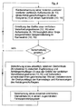
In
- In einem ersten Verfahrensschritt erfolgt eine Kantenerkennung einer, in Fahrzeug-Längsrichtung x gesehen, hinteren und/oder vorderen vertikalen Außenkante 8, 13 des
Aufliegers 3 des Gespannes 1 ineinem Kamerabild seitlichen Verschiebungsstrecke einer Außenkante im Kamerabild Wenn eine Verschiebungsstrecke
- In a first method step, an edge recognition of a rear and / or front vertical
outer edge trailer 3 of the trailer 1 in avehicle image lateral displacement distance outer edge camera image displacement path displacement distance
- 11
- Nutzfahrzeug-GespannCommercial vehicle trailer
- 22
- Zugfahrzeugtowing vehicle
- 33
- Aufliegersemitrailer
- 44
- Auflieger-DrehpunktSemi-fulcrum
- 55
- Knickwinkel (relativer Gierwinkel)Bending angle (relative yaw angle)
- 66
- Kameracamera
- 77
- Kameracamera
- 8, 8'8, 8 '
- hintere, vertikale Außenkanterear, vertical outer edge
- 99
- vertikales Kamerabildvertical camera image
- 1010
- horizontales Kamerabildhorizontal camera image
- 1111
- strichlierte Liniedashed line
- 1212
- Verschiebestreckedisplacement distance
- 13, 13'13, 13 '
- vordere, vertikale Außenkantefront, vertical outer edge
- 1414
- vertikales Kamerabildvertical camera image
- 1515
- horizontales Kamerabildhorizontal camera image
- 1616
- Verschiebestreckedisplacement distance
- 1717
- Lotsenkrechteplumb
- 1818
- Bodenebeneground level
- 1919
- relativer Wankwinkelrelative roll angle
Claims (15)
dadurch gekennzeichnet,
dass aus dem Kamerabild (10, 15) wenigstens einer, insbesondere in Fahrzeug-Längsrichtung (x) ausgerichteten, Kamera (6, 7) des Nutzfahrzeugs mittels einer Bildverarbeitungsvorrichtung wenigstens eine fahrdynamische Information über das Nutzfahrzeug, insbesondere über einen Anhänger/Auflieger (3) und/oder ein Zugfahrzeug (2) eines Nutzfahrzeug-Gespanns (1) extrahiert wird.Method for determining the driving dynamics of a commercial vehicle,
characterized,
in that from the camera image (10, 15) of at least one camera (6, 7) of the utility vehicle, in particular in the vehicle longitudinal direction (x), at least one vehicle dynamics information about the commercial vehicle, in particular a trailer / semitrailer (3), by means of an image processing device. and / or a towing vehicle (2) of a commercial vehicle combination (1) is extracted.
dass eine Information der relative Gierwinkel als Knickwinkel (5) zwischen Zugfahrzeug (2) und Anhänger/Auflieger (3) ist und dieser dergestalt ermittelt wird,
dass eine, in Fahrzeug-Längsrichtung (x) gesehen, vordere, vertikale Außenkante (13) eines Anhängers/Aufliegers (3) von mindestens einer je Fahrzeugseite, in Fahrzeug-Längsrichtung (x) gesehen, nach hinten gerichteten Kamera (6) erfasst wird,
dass die aktuelle Kantenposition der vorderen Außenkante (13), insbesondere die Größe einer, in Fahrzeugquerrichtung (y) gesehen, seitlichen Verschiebungsstrecke (16), bezüglich einer Kantenposition (13') bei einer längs ausgerichteten Gespannstellung ermittelt wird, und
dass aus dieser aktuellen Kantenposition (13) und unveränderlichen geometrischen Werten, insbesondere der Lage des Anhänger/Auflieger-Drehpunkts (4) und der Anhänger/Auflieger-Breite, der relative Gierwinkel zwischen Zugfahrzeug (2) und Anhänger/Auflieger (3) als Knickwinkel (5) berechnet wird.Method according to claim 1 or claim 2, characterized
that information is the relative yaw angle as the bending angle (5) between towing vehicle (2) and trailer / semitrailer (3) and this is determined in such a way,
in that a front, vertical outer edge (13) of a trailer / semi-trailer (3) seen in the vehicle longitudinal direction (x) is detected by at least one rear-facing camera (6) per vehicle side, viewed in the vehicle longitudinal direction (x) .
that the current edge position of the front outer edge (13), in particular the size of a, in the vehicle transverse direction (y) seen, lateral displacement distance (16), with respect to an edge position (13 ') is determined in a longitudinally aligned Gespannstellung, and
that from this current edge position (13) and invariable geometric values, in particular the position of the trailer / semi-trailer pivot point (4) and the trailer / semi-trailer width, the relative yaw angle between towing vehicle (2) and trailer / semitrailer (3) as a bending angle (5) is calculated.
dass eine, in Fahrzeug-Längsrichtung (x) gesehen, hintere, vertikale Außenkante (8) eines Anhängers/Aufliegers (5) von mindestens einer, in Fahrzeug-Längsrichtung (x) gesehen, nach hinten gerichteten Kamera (7) je Fahrzeugseite erfasst wird,
dass die aktuelle Kantenposition der hinteren Außenkante (8) ermittelt wird, und
dass aus dieser aktuellen Kantenposition (8) sowie der Lage des Anhänger/Auflieger-Drehpunkts (4) sowie Länge und Breite des Anhängers/Aufliegers (3) der eine Information ausbildende relative Gierwinkel als Knickwinkel (5) berechnet wird.Method according to one of claims 1 to 3, characterized
in that a rear, vertical outer edge (8) of a trailer / semi-trailer (5) seen in the vehicle longitudinal direction (x) is detected by at least one camera (7) per vehicle side viewed in the vehicle longitudinal direction (x) .
that the current edge position of the rear outer edge (8) is determined, and
that from this current edge position (8) and the position of the trailer / semitrailer pivot point (4) and length and width of the trailer / semitrailer (3) of an information forming relative yaw angle is calculated as kink angle (5).
dass eine Information der relative Wankwinkel (19) eines Anhängers/Aufliegers (3) ist und dieser dergestalt ermittelt wird,
dass eine, in Fahrzeug-Längsrichtung (x) gesehen, hintere und/oder vordere vertikale Außenkante (8) eines Anhänger/Aufliegers (3) von mindestens einer je Fahrzeugseite, in Fahrzeug-Längsrichtung (x) gesehen, nach hinten gerichteten Kamera (7) erfasst wird,
dass eine Lotsenkrechte (17) zur Bodenebene (18) bestimmt wird, und
dass in einer Winkelauswertung der aktuelle, relative Wankwinkel (19) als Winkel zwischen der Lotsenkrechten (17) und der hinteren und/oder vorderen vertikalen Außenkante (8) des Anhängers/Aufliegers (3) bestimmt wird.Method according to claim 1 or claim 2, characterized
that information is the relative roll angle (19) of a trailer / semitrailer (3) and this is determined in such a way that
in that a rear and / or front vertical outer edge (8) of a trailer / semitrailer (3) seen in the vehicle longitudinal direction (x) extends from at least one rear-facing camera (7) in the vehicle longitudinal direction (x) ) is detected,
that a vertical perpendicular (17) to the ground plane (18) is determined, and
that as the angle between vertical in in an angular evaluation of the current, relative roll angle (19) (17) and the rear and / or front vertical outer edge (8) of the trailer / semi-trailer (3) is determined.
dass aus einer bekannten Einbauposition und Ausrichtung einer am Zugfahrzeug (2), insbesondere am Fahrerhaus angeordneten Kamera (6, 7) die Lage der Lotsenkrechten (17) zur Bodenebene (18) bestimmt wird, wobei gegebenenfalls ein Wanken des Fahrerhauses festgestellt und korrigierend berücksichtigt wird, und/oder
dass die Bodenebene (18) bestimmt wird, insbesondere mittels einer Stereokamera.Method according to Claim 6, characterized
in that the position of the vertical perpendicular (17) to the ground plane (18) is determined from a known installation position and orientation of a camera (6, 7) arranged on the towing vehicle (2), in particular on the driver's cab, optionally detecting a roll of the driver's cab and taking corrective action into account , and or
that the ground plane (18) is determined, in particular by means of a stereo camera.
dass eine Information ein Fahrzeugstillstand und/oder eine geringe Rollgeschwindigkeit ist und diese/r gegebenenfalls in Verbindung mit der Bewegungsrichtung dergestalt ermittelt wird,
dass aus einem Kamerabild (10, 15) mittels der Bildverarbeitungsvorrichtung, insbesondere einen optischen Fluss, eine Relativbewegung oder ein Stillstand zwischen dem Nutzfahrzeug-Gespann (1) und einem erfassten Hintergrund, insbesondere einer Fahrbahn (18), erkannt und der ermittelte Zustand in einem Fahrerassistenzsystem verwendet wird.Method according to claim 1 or claim 2, characterized
that information is a vehicle standstill and / or a low rolling speed and this is optionally determined in connection with the direction of movement,
that from a camera image (10, 15) by means of the image processing device, in particular an optical flow, a relative movement or a standstill between the commercial vehicle team (1) and a detected background, in particular a roadway (18), recognized and the determined state in one Driver assistance system is used.
dass aus dem Kamerabild (10, 15) wenigstens einer, insbesondere in Fahrzeug-Längsrichtung (x) ausgerichteten, Kamera (6, 7) des Nutzfahrzeugs mittels einer Bildverarbeitungsvorrichtung wenigstens eine fahrdynamische Information über das Nutzfahrzeug, insbesondere über einen Anhänger/Auflieger (3) und/oder ein Zugfahrzeug (2) eines Nutzfahrzeug-Gespanns (1) extrahierbar ist.Driver assistance system for determining the driving dynamics of a commercial vehicle, characterized in that
in that from the camera image (10, 15) of at least one camera (6, 7) of the utility vehicle, in particular in the vehicle longitudinal direction (x), at least one vehicle dynamics information about the commercial vehicle, in particular a trailer / semitrailer (3), by means of an image processing device. and / or a towing vehicle (2) of a commercial vehicle combination (1) can be extracted.
dass eine Information ein relativer Gierwinkel als Knickwinkel (5) zwischen Zugfahrzeug (2) und Anhänger/Auflieger (3) ist und dieser dergestalt ermittelbar ist,
dass eine, in Fahrzeug-Längsrichtung (x) gesehen, vordere, und/oder hintere vertikale Außenkante (13; 8) eines Anhängers/Aufliegers (3) von mindestens einer je Fahrzeugseite, in Fahrzeug-Längsrichtung (x) gesehen, nach hinten gerichteten Kamera (6; 7) erfassbar ist,
dass die aktuelle Kantenposition der vorderen und/oder hinteren Außenkante (13; 8), insbesondere die Größe einer, in Fahrzeug-Querrichtung (y) gesehen, seitlichen Verschiebungsstrecke (16; 22), bezüglich einer Kantenposition (13'; 8') bei einer längs ausgerichteten Gespannstellung ermittelbar ist,
dass aus der aktuellen Kantenposition (13; 8) und unveränderlichen geometrischen Werten, insbesondere der Lage des Anhänger/Auflieger-Drehpunkts (4) und der Anhänger/Auflieger-Breite, der relative Gierwinkel zwischen Zugfahrzeug (2) und Anhänger/Auflieger (3) als Knickwinkel (5) berechenbar ist.Driver assistance system according to claim 10, characterized in that
that information is a relative yaw angle as a bending angle (5) between towing vehicle (2) and trailer / semi-trailer (3) and can be determined in this way,
in that a front and / or rear vertical outer edge (13; 8) of a trailer / semitrailer (3) viewed in the vehicle longitudinal direction (x) faces backwards from at least one per vehicle side, viewed in the vehicle longitudinal direction (x) Camera (6; 7) is detectable,
in that the current edge position of the front and / or rear outer edge (13; 8), in particular the size of a lateral displacement path seen in the vehicle transverse direction (y) (16; 22), with respect to an edge position (13 ';8') can be determined in a longitudinally aligned Gespannstellung,
that the relative yaw angle between towing vehicle (2) and trailer / semi-trailer (3) is determined from the current edge position (13; 8) and invariable geometric values, in particular the position of the trailer / semitrailer pivot point (4) and the trailer / trailer width. as a bending angle (5) is calculable.
dass eine Information ein relativer Wankwinkel (19) eines Anhängers/Aufliegers (3) ist und dieser dergestalt ermittelbar ist,
dass eine, in Fahrzeug-Längsrichtung (x) gesehen, hintere und/oder vordere vertikale Außenkante (8) eines Anhänger/Aufliegers (3) von mindestens einer je Fahrzeugseite, in Fahrzeug-Längsrichtung (x) gesehen, nach hinten gerichteten Kamera (7) erfassbar ist,
dass eine Lotsenkrechte (17) zur Bodenebene (18) bestimmbar ist,
dass in einer Winkelauswertung der aktuelle, relative Wankwinkel (19) als Winkel zwischen der Lotsenkrechten (17) und der hinteren und/oder vorderen vertikalen Außenkante (8) des Anhängers/Aufliegers (3) bestimmbar ist.Driver assistance system according to claim 10, characterized in that
that information is a relative roll angle (19) of a trailer / semitrailer (3) and can be determined in this way,
in that a rear and / or front vertical outer edge (8) of a trailer / semitrailer (3) seen in the vehicle longitudinal direction (x) extends from at least one rear-facing camera (7) in the vehicle longitudinal direction (x) ) is detectable,
that a vertical perpendicular (17) to the ground plane (18) can be determined,
that as the angle between vertical in in an angular evaluation of the current, relative roll angle (19) (17) and the rear and / or front vertical outer edge (8) of the trailer / semi-trailer (3) can be determined.
dass damit aus einer bekannten Einbauposition und Ausrichtung einer am Zugfahrzeug (2), insbesondere am Fahrerhaus angeordneten Kamera (6, 7) die Lage der Lotsenkrechten (17) zur Bodenebene (18) bestimmbar ist, wobei gegebenenfalls ein Wanken des Fahrerhauses feststellbar und korrigierend berücksichtigbar ist, und/oder dass die Bodenebene (18) mittels einer Stereokamera bestimmbar ist.Driver assistance system according to claim 12, characterized in that
that is from a known installation position and orientation of the towing vehicle (2), in particular on the cab arranged camera (6, 7), the position of Lotsenkrechten (17) to the ground plane (18) can be determined, where appropriate, a roll of the cab detectable and corrective considered is, and / or that the ground plane (18) can be determined by means of a stereo camera.
dass eine Information ein Fahrzeugstillstand und/oder eine geringe Rollgeschwindigkeit ist und diese/r gegebenenfalls in Verbindung mit der Bewegungsrichtung dergestalt ermittelbar ist,
dass aus einem Kamerabild (10, 15) mittels der Bildverarbeitungsvorrichtung, insbesondere durch einen optischen Fluss eine Relativbewegung oder ein Stillstand zwischen dem Nutzfahrzeug-Gespann (1) und einem erfassten Hintergrund, insbesondere einer Fahrbahn (18) erkennbar ist, und/oder
dass bei Ermittlung einer Relativbewegung durch Auswertung von Bewegungsvektoren des optischen Flusses die Bewegungsrichtung des Nutfahrzeug-Gespanns (vorwärts oder rückwärts) extrahierbar ist.Driver assistance system according to claim 10, characterized in that
that information is a vehicle standstill and / or a low rolling speed and this can optionally be determined in connection with the direction of movement,
in that from a camera image (10, 15) by means of the image processing device, in particular by an optical flow, a relative movement or a standstill between the commercial vehicle team (1) and a detected background, in particular a roadway (18) is recognizable, and / or
that when determining a relative movement by evaluating motion vectors of the optical flow, the direction of movement of the grooming vehicle combination (forward or backward) can be extracted.
Priority Applications (2)
| Application Number | Priority Date | Filing Date | Title |
|---|---|---|---|
| EP18154740.7A EP3351451B1 (en) | 2014-05-27 | 2015-03-24 | Method and driver assistance system for determining dynamic driving states in a commercial vehicle |
| EP18154738.1A EP3351450B1 (en) | 2014-05-27 | 2015-03-24 | Method and driver assistance system for determining dynamic driving states in a commercial vehicle |
Applications Claiming Priority (1)
| Application Number | Priority Date | Filing Date | Title |
|---|---|---|---|
| DE102014007900.7A DE102014007900A1 (en) | 2014-05-27 | 2014-05-27 | Method and driver assistance system for determining the driving dynamics of a commercial vehicle |
Related Child Applications (4)
| Application Number | Title | Priority Date | Filing Date |
|---|---|---|---|
| EP18154738.1A Division-Into EP3351450B1 (en) | 2014-05-27 | 2015-03-24 | Method and driver assistance system for determining dynamic driving states in a commercial vehicle |
| EP18154738.1A Division EP3351450B1 (en) | 2014-05-27 | 2015-03-24 | Method and driver assistance system for determining dynamic driving states in a commercial vehicle |
| EP18154740.7A Division-Into EP3351451B1 (en) | 2014-05-27 | 2015-03-24 | Method and driver assistance system for determining dynamic driving states in a commercial vehicle |
| EP18154740.7A Division EP3351451B1 (en) | 2014-05-27 | 2015-03-24 | Method and driver assistance system for determining dynamic driving states in a commercial vehicle |
Publications (3)
| Publication Number | Publication Date |
|---|---|
| EP2949531A2 true EP2949531A2 (en) | 2015-12-02 |
| EP2949531A3 EP2949531A3 (en) | 2017-04-26 |
| EP2949531B1 EP2949531B1 (en) | 2021-06-30 |
Family
ID=52780756
Family Applications (3)
| Application Number | Title | Priority Date | Filing Date |
|---|---|---|---|
| EP15000865.4A Active EP2949531B1 (en) | 2014-05-27 | 2015-03-24 | Method and driver assistance system for determining dynamic driving states in a commercial vehicle |
| EP18154738.1A Active EP3351450B1 (en) | 2014-05-27 | 2015-03-24 | Method and driver assistance system for determining dynamic driving states in a commercial vehicle |
| EP18154740.7A Active EP3351451B1 (en) | 2014-05-27 | 2015-03-24 | Method and driver assistance system for determining dynamic driving states in a commercial vehicle |
Family Applications After (2)
| Application Number | Title | Priority Date | Filing Date |
|---|---|---|---|
| EP18154738.1A Active EP3351450B1 (en) | 2014-05-27 | 2015-03-24 | Method and driver assistance system for determining dynamic driving states in a commercial vehicle |
| EP18154740.7A Active EP3351451B1 (en) | 2014-05-27 | 2015-03-24 | Method and driver assistance system for determining dynamic driving states in a commercial vehicle |
Country Status (5)
| Country | Link |
|---|---|
| EP (3) | EP2949531B1 (en) |
| CN (3) | CN111469850A (en) |
| BR (1) | BR102015008484B1 (en) |
| DE (1) | DE102014007900A1 (en) |
| RU (1) | RU2689565C2 (en) |
Cited By (2)
| Publication number | Priority date | Publication date | Assignee | Title |
|---|---|---|---|---|
| WO2019084398A1 (en) * | 2017-10-26 | 2019-05-02 | Uber Technologies, Inc. | Systems and methods for determining tractor-trailer angles and distances |
| WO2024030550A1 (en) * | 2022-08-04 | 2024-02-08 | Caterpillar Trimble Control Technologies Llc | Yaw estimation systems and methods for rigid bodies of earthmoving machines connected by a revolute joint |
Families Citing this family (10)
| Publication number | Priority date | Publication date | Assignee | Title |
|---|---|---|---|---|
| DE102016222549B4 (en) * | 2016-11-16 | 2019-05-16 | Audi Ag | Method for determining trailer information and motor vehicle |
| DE102017011177A1 (en) | 2017-12-05 | 2019-06-06 | Wabco Gmbh | Method for determining a bending angle of a vehicle combination, determination device and vehicle combination |
| DE102018200861A1 (en) * | 2018-01-19 | 2019-07-25 | Robert Bosch Gmbh | Method and device for video-based monitoring of a component element of a freight motor vehicle |
| CN109348401B (en) * | 2018-09-21 | 2023-11-17 | 交通运输部公路科学研究所 | System and method for monitoring running gesture of automobile train based on wireless positioning technology |
| DE102019206985A1 (en) * | 2019-05-14 | 2020-11-19 | Robert Bosch Gmbh | Method for determining an operating angle between a tractor and a trailer of the tractor |
| DE102019217988A1 (en) * | 2019-11-21 | 2021-05-27 | Zf Friedrichshafen Ag | Camera-based detection of tilting movements |
| EP3922526B1 (en) * | 2020-06-09 | 2023-09-20 | Elektrobit Automotive GmbH | Determination of a roll angle or pitch angle of a mode of transport |
| CN112362055B (en) * | 2020-12-01 | 2022-12-30 | 苏州挚途科技有限公司 | Attitude estimation method and device and electronic equipment |
| DE102021208819A1 (en) | 2021-08-12 | 2023-02-16 | Robert Bosch Gesellschaft mit beschränkter Haftung | Method for determining a kink angle |
| DE102023114252A1 (en) | 2023-05-31 | 2023-09-14 | Daimler Truck AG | Driver assistance system for controlling a tractor-trailer and method |
Family Cites Families (19)
| Publication number | Priority date | Publication date | Assignee | Title |
|---|---|---|---|---|
| JP2003019984A (en) * | 2001-07-06 | 2003-01-21 | Nissan Diesel Motor Co Ltd | Relative roll angle detecting device for trailer and vehicle roll over preventive device |
| DE10326190A1 (en) * | 2003-06-06 | 2004-12-30 | Daimlerchrysler Ag | Apparatus and method for determining a spatial orientation of a hanger or trailer |
| DE102004009187A1 (en) * | 2004-02-25 | 2005-09-15 | Daimlerchrysler Ag | Control system for a team |
| DE102004022113A1 (en) * | 2004-05-05 | 2005-11-24 | Robert Bosch Gmbh | Monitoring a car trailer with a reversing camera |
| US7330861B2 (en) * | 2004-09-10 | 2008-02-12 | Hitachi, Ltd. | Remote copying system and method of controlling remote copying |
| DE102005042957A1 (en) * | 2005-09-09 | 2007-03-22 | Daimlerchrysler Ag | Drawbar angle and trailer angle determining method, involves determining geometric ratios and/or relative position of characteristics edges and lines of drawbar and front side of trailer to find drawbar angle and trailer angle |
| DE102004060402A1 (en) * | 2004-12-14 | 2006-07-13 | Adc Automotive Distance Control Systems Gmbh | Method and device for determining a vehicle speed |
| DE102005014114A1 (en) * | 2005-03-21 | 2006-10-05 | Valeo Schalter Und Sensoren Gmbh | Track recognition system and method |
| EP1921867B1 (en) * | 2006-10-17 | 2016-05-25 | Harman Becker Automotive Systems GmbH | Sensor assisted video compression |
| DE102006056408B4 (en) * | 2006-11-29 | 2013-04-18 | Universität Koblenz-Landau | Method for determining a position, device and computer program product |
| DE102007032720A1 (en) * | 2007-07-13 | 2009-01-15 | Daimler Ag | Driver assisting method for use during shunting or parking of vehicle e.g. vehicle with trailer, involves implementing simulation for determining optimal trajectory or motion sequence of vehicle and displaying trajectory or sequence |
| DE102009055776A1 (en) * | 2009-11-25 | 2011-05-26 | Conti Temic Microelectronic Gmbh | Method for estimating the roll angle in a moving vehicle |
| DE102010006323B4 (en) * | 2010-01-29 | 2013-07-04 | Continental Teves Ag & Co. Ohg | Stereo camera for vehicles with trailer |
| DE102011114977A1 (en) * | 2011-07-05 | 2013-01-10 | Wabco Gmbh | Device and method for controlling the driving dynamics of a vehicle and vehicle with such a device |
| DE102012003027A1 (en) * | 2012-02-15 | 2012-10-11 | Daimler Ag | Driver assistance system for signaling lane change warning to driver or for automatic tracking of vehicle, particularly commercial vehicle, has camera in front area of vehicle, whose vertical proximal detection area is predetermined |
| DE102012203037A1 (en) * | 2012-02-28 | 2013-08-29 | Continental Automotive Gmbh | Method for determining the speed and / or position of a vehicle |
| SE536571C2 (en) * | 2012-06-12 | 2014-02-25 | A method and system for lane assistance for a vehicle | |
| DE102012016708A1 (en) * | 2012-08-22 | 2014-05-15 | Wabco Gmbh | Method for monitoring inside curve of maneuver space of road train, during cornering, involves deflecting scanning beam from parallel output direction to associated side surface depending on inclination angles of road train to form base leg |
| CN103686083B (en) * | 2013-12-09 | 2017-01-11 | 北京理工大学 | Real-time speed measurement method based on vehicle-mounted sensor video streaming matching |
-
2014
- 2014-05-27 DE DE102014007900.7A patent/DE102014007900A1/en not_active Ceased
-
2015
- 2015-03-24 EP EP15000865.4A patent/EP2949531B1/en active Active
- 2015-03-24 EP EP18154738.1A patent/EP3351450B1/en active Active
- 2015-03-24 EP EP18154740.7A patent/EP3351451B1/en active Active
- 2015-04-15 BR BR102015008484-6A patent/BR102015008484B1/en active IP Right Grant
- 2015-04-27 RU RU2015115884A patent/RU2689565C2/en active
- 2015-05-27 CN CN201911355746.3A patent/CN111469850A/en active Pending
- 2015-05-27 CN CN201911357667.6A patent/CN111469851A/en active Pending
- 2015-05-27 CN CN201510276899.4A patent/CN105270408B/en active Active
Non-Patent Citations (1)
| Title |
|---|
| None |
Cited By (2)
| Publication number | Priority date | Publication date | Assignee | Title |
|---|---|---|---|---|
| WO2019084398A1 (en) * | 2017-10-26 | 2019-05-02 | Uber Technologies, Inc. | Systems and methods for determining tractor-trailer angles and distances |
| WO2024030550A1 (en) * | 2022-08-04 | 2024-02-08 | Caterpillar Trimble Control Technologies Llc | Yaw estimation systems and methods for rigid bodies of earthmoving machines connected by a revolute joint |
Also Published As
| Publication number | Publication date |
|---|---|
| RU2689565C2 (en) | 2019-05-28 |
| BR102015008484A2 (en) | 2016-01-26 |
| CN105270408A (en) | 2016-01-27 |
| CN105270408B (en) | 2020-01-21 |
| RU2015115884A (en) | 2016-11-20 |
| EP2949531B1 (en) | 2021-06-30 |
| EP3351451B1 (en) | 2024-05-01 |
| EP3351451A1 (en) | 2018-07-25 |
| BR102015008484B1 (en) | 2022-04-26 |
| EP2949531A3 (en) | 2017-04-26 |
| RU2015115884A3 (en) | 2018-11-14 |
| CN111469850A (en) | 2020-07-31 |
| CN111469851A (en) | 2020-07-31 |
| EP3351450A1 (en) | 2018-07-25 |
| DE102014007900A1 (en) | 2015-12-03 |
| EP3351450B1 (en) | 2021-11-03 |
Similar Documents
| Publication | Publication Date | Title |
|---|---|---|
| EP3351450B1 (en) | Method and driver assistance system for determining dynamic driving states in a commercial vehicle | |
| DE112012000466B4 (en) | System and method for maneuvering a vehicle-trailer combination when reversing | |
| EP1593552B1 (en) | System and method for monitoring a car trailer | |
| DE102005009814B4 (en) | Vehicle condition detection system and method | |
| DE102018129823A1 (en) | Monitor the orientation of the vehicle suspension system | |
| DE112010005448T5 (en) | Collision judgment device for a vehicle | |
| DE102010055583B4 (en) | Motor vehicle with a camera and method for operating a camera system in a motor vehicle | |
| DE102009032024A1 (en) | A method for determining a position of a trailer attached to a vehicle relative to the vehicle and driver assistance system for a vehicle | |
| WO2014041209A1 (en) | Method for determining the orientation of a parking space, parking assistance system, and motor vehicle | |
| DE102019112640A1 (en) | CONTROLLING A VEHICLE BASED ON TRAILER VIBRATION | |
| EP1327969A1 (en) | Vehicle with means for recognising traffic road signs | |
| DE102013022076A1 (en) | Method for determining a width of a target vehicle by means of a camera system of a motor vehicle, camera system and motor vehicle | |
| DE102008025773A1 (en) | Local and movement conditions estimating method for observed object i.e. vehicle, involves determining distance, detecting shifting of portion of object, and estimating parameter of local and movement condition | |
| AT518940A1 (en) | A method and apparatus for measuring a distance between a first vehicle and a second vehicle immediately ahead of the first vehicle | |
| EP2715666A1 (en) | Method for determining a pitching movement in a camera installed in a vehicle, and method for controlling a light emission from at least one headlamp on a vehicle | |
| DE102014218995A1 (en) | Method and device for bird-view display of a vehicle combination and retrofittable camera | |
| DE10125966A1 (en) | Curve warning system for drivers of long vehicles, such as buses or goods vehicles, has a rear facing sensor arrangement and a control computer for calculating if an impact will occur and warning the driver accordingly | |
| EP3520020B1 (en) | Road sign classification in a surrounding area of a motor vehicle | |
| DE102011080720A1 (en) | Method for predictive monitoring of track in driving assistance system of vehicle, involves detecting environmental data concerning to track section by environment sensor system of vehicle before detecting gradient change | |
| EP2287060A1 (en) | Method for determining whether a motor vehicle in front is changing lane | |
| EP2942253A2 (en) | Motor vehicle | |
| DE102018004110A1 (en) | Method and control arrangement for modeling a spatial movement of a trailer, which is hinged to a vehicle | |
| DE102018006758B4 (en) | Vehicle camera system and method for capturing images in front of a vehicle | |
| EP2688768A1 (en) | Driver assistance system and driver assistance method for a vehicle | |
| DE102018203203A1 (en) | Control of a motor vehicle team |
Legal Events
| Date | Code | Title | Description |
|---|---|---|---|
| AK | Designated contracting states |
Kind code of ref document: A2 Designated state(s): AL AT BE BG CH CY CZ DE DK EE ES FI FR GB GR HR HU IE IS IT LI LT LU LV MC MK MT NL NO PL PT RO RS SE SI SK SM TR |
|
| AX | Request for extension of the european patent |
Extension state: BA ME |
|
| PUAI | Public reference made under article 153(3) epc to a published international application that has entered the european phase |
Free format text: ORIGINAL CODE: 0009012 |
|
| RIN1 | Information on inventor provided before grant (corrected) |
Inventor name: KRAUS, SVEN Inventor name: SCHWERTBERGER, WALTER Inventor name: REULE, MICHAEL Inventor name: ROEMERSPERGER, XAVER Inventor name: DOERNER, KARLHEINZ |
|
| PUAL | Search report despatched |
Free format text: ORIGINAL CODE: 0009013 |
|
| AK | Designated contracting states |
Kind code of ref document: A3 Designated state(s): AL AT BE BG CH CY CZ DE DK EE ES FI FR GB GR HR HU IE IS IT LI LT LU LV MC MK MT NL NO PL PT RO RS SE SI SK SM TR |
|
| AX | Request for extension of the european patent |
Extension state: BA ME |
|
| RIC1 | Information provided on ipc code assigned before grant |
Ipc: B60W 40/10 20120101AFI20170323BHEP |
|
| STAA | Information on the status of an ep patent application or granted ep patent |
Free format text: STATUS: REQUEST FOR EXAMINATION WAS MADE |
|
| 17P | Request for examination filed |
Effective date: 20171026 |
|
| RAP1 | Party data changed (applicant data changed or rights of an application transferred) |
Owner name: MAN TRUCK & BUS SE |
|
| REG | Reference to a national code |
Ref country code: DE Ref legal event code: R079 Ref document number: 502015014864 Country of ref document: DE Free format text: PREVIOUS MAIN CLASS: B60W0040100000 Ipc: B60W0030020000 |
|
| RIC1 | Information provided on ipc code assigned before grant |
Ipc: B60W 40/10 20120101ALI20201127BHEP Ipc: B60W 30/06 20060101ALI20201127BHEP Ipc: B60W 30/02 20120101AFI20201127BHEP Ipc: B60W 40/105 20120101ALI20201127BHEP |
|
| GRAP | Despatch of communication of intention to grant a patent |
Free format text: ORIGINAL CODE: EPIDOSNIGR1 |
|
| STAA | Information on the status of an ep patent application or granted ep patent |
Free format text: STATUS: GRANT OF PATENT IS INTENDED |
|
| INTG | Intention to grant announced |
Effective date: 20210128 |
|
| GRAS | Grant fee paid |
Free format text: ORIGINAL CODE: EPIDOSNIGR3 |
|
| GRAA | (expected) grant |
Free format text: ORIGINAL CODE: 0009210 |
|
| STAA | Information on the status of an ep patent application or granted ep patent |
Free format text: STATUS: THE PATENT HAS BEEN GRANTED |
|
| AK | Designated contracting states |
Kind code of ref document: B1 Designated state(s): AL AT BE BG CH CY CZ DE DK EE ES FI FR GB GR HR HU IE IS IT LI LT LU LV MC MK MT NL NO PL PT RO RS SE SI SK SM TR |
|
| REG | Reference to a national code |
Ref country code: CH Ref legal event code: EP |
|
| REG | Reference to a national code |
Ref country code: AT Ref legal event code: REF Ref document number: 1406106 Country of ref document: AT Kind code of ref document: T Effective date: 20210715 |
|
| REG | Reference to a national code |
Ref country code: DE Ref legal event code: R096 Ref document number: 502015014864 Country of ref document: DE |
|
| REG | Reference to a national code |
Ref country code: IE Ref legal event code: FG4D Free format text: LANGUAGE OF EP DOCUMENT: GERMAN |
|
| REG | Reference to a national code |
Ref country code: NL Ref legal event code: FP |
|
| REG | Reference to a national code |
Ref country code: SE Ref legal event code: TRGR |
|
| REG | Reference to a national code |
Ref country code: LT Ref legal event code: MG9D |
|
| PG25 | Lapsed in a contracting state [announced via postgrant information from national office to epo] |
Ref country code: BG Free format text: LAPSE BECAUSE OF FAILURE TO SUBMIT A TRANSLATION OF THE DESCRIPTION OR TO PAY THE FEE WITHIN THE PRESCRIBED TIME-LIMIT Effective date: 20210930 Ref country code: FI Free format text: LAPSE BECAUSE OF FAILURE TO SUBMIT A TRANSLATION OF THE DESCRIPTION OR TO PAY THE FEE WITHIN THE PRESCRIBED TIME-LIMIT Effective date: 20210630 Ref country code: HR Free format text: LAPSE BECAUSE OF FAILURE TO SUBMIT A TRANSLATION OF THE DESCRIPTION OR TO PAY THE FEE WITHIN THE PRESCRIBED TIME-LIMIT Effective date: 20210630 |
|
| PG25 | Lapsed in a contracting state [announced via postgrant information from national office to epo] |
Ref country code: LV Free format text: LAPSE BECAUSE OF FAILURE TO SUBMIT A TRANSLATION OF THE DESCRIPTION OR TO PAY THE FEE WITHIN THE PRESCRIBED TIME-LIMIT Effective date: 20210630 Ref country code: GR Free format text: LAPSE BECAUSE OF FAILURE TO SUBMIT A TRANSLATION OF THE DESCRIPTION OR TO PAY THE FEE WITHIN THE PRESCRIBED TIME-LIMIT Effective date: 20211001 Ref country code: RS Free format text: LAPSE BECAUSE OF FAILURE TO SUBMIT A TRANSLATION OF THE DESCRIPTION OR TO PAY THE FEE WITHIN THE PRESCRIBED TIME-LIMIT Effective date: 20210630 Ref country code: NO Free format text: LAPSE BECAUSE OF FAILURE TO SUBMIT A TRANSLATION OF THE DESCRIPTION OR TO PAY THE FEE WITHIN THE PRESCRIBED TIME-LIMIT Effective date: 20210930 |
|
| PG25 | Lapsed in a contracting state [announced via postgrant information from national office to epo] |
Ref country code: CZ Free format text: LAPSE BECAUSE OF FAILURE TO SUBMIT A TRANSLATION OF THE DESCRIPTION OR TO PAY THE FEE WITHIN THE PRESCRIBED TIME-LIMIT Effective date: 20210630 Ref country code: EE Free format text: LAPSE BECAUSE OF FAILURE TO SUBMIT A TRANSLATION OF THE DESCRIPTION OR TO PAY THE FEE WITHIN THE PRESCRIBED TIME-LIMIT Effective date: 20210630 Ref country code: SK Free format text: LAPSE BECAUSE OF FAILURE TO SUBMIT A TRANSLATION OF THE DESCRIPTION OR TO PAY THE FEE WITHIN THE PRESCRIBED TIME-LIMIT Effective date: 20210630 Ref country code: SM Free format text: LAPSE BECAUSE OF FAILURE TO SUBMIT A TRANSLATION OF THE DESCRIPTION OR TO PAY THE FEE WITHIN THE PRESCRIBED TIME-LIMIT Effective date: 20210630 Ref country code: ES Free format text: LAPSE BECAUSE OF FAILURE TO SUBMIT A TRANSLATION OF THE DESCRIPTION OR TO PAY THE FEE WITHIN THE PRESCRIBED TIME-LIMIT Effective date: 20210630 Ref country code: RO Free format text: LAPSE BECAUSE OF FAILURE TO SUBMIT A TRANSLATION OF THE DESCRIPTION OR TO PAY THE FEE WITHIN THE PRESCRIBED TIME-LIMIT Effective date: 20210630 Ref country code: PT Free format text: LAPSE BECAUSE OF FAILURE TO SUBMIT A TRANSLATION OF THE DESCRIPTION OR TO PAY THE FEE WITHIN THE PRESCRIBED TIME-LIMIT Effective date: 20211102 |
|
| PG25 | Lapsed in a contracting state [announced via postgrant information from national office to epo] |
Ref country code: PL Free format text: LAPSE BECAUSE OF FAILURE TO SUBMIT A TRANSLATION OF THE DESCRIPTION OR TO PAY THE FEE WITHIN THE PRESCRIBED TIME-LIMIT Effective date: 20210630 |
|
| REG | Reference to a national code |
Ref country code: DE Ref legal event code: R097 Ref document number: 502015014864 Country of ref document: DE |
|
| PG25 | Lapsed in a contracting state [announced via postgrant information from national office to epo] |
Ref country code: DK Free format text: LAPSE BECAUSE OF FAILURE TO SUBMIT A TRANSLATION OF THE DESCRIPTION OR TO PAY THE FEE WITHIN THE PRESCRIBED TIME-LIMIT Effective date: 20210630 |
|
| PLBE | No opposition filed within time limit |
Free format text: ORIGINAL CODE: 0009261 |
|
| STAA | Information on the status of an ep patent application or granted ep patent |
Free format text: STATUS: NO OPPOSITION FILED WITHIN TIME LIMIT |
|
| PG25 | Lapsed in a contracting state [announced via postgrant information from national office to epo] |
Ref country code: AL Free format text: LAPSE BECAUSE OF FAILURE TO SUBMIT A TRANSLATION OF THE DESCRIPTION OR TO PAY THE FEE WITHIN THE PRESCRIBED TIME-LIMIT Effective date: 20210630 |
|
| 26N | No opposition filed |
Effective date: 20220331 |
|
| PG25 | Lapsed in a contracting state [announced via postgrant information from national office to epo] |
Ref country code: MC Free format text: LAPSE BECAUSE OF FAILURE TO SUBMIT A TRANSLATION OF THE DESCRIPTION OR TO PAY THE FEE WITHIN THE PRESCRIBED TIME-LIMIT Effective date: 20210630 |
|
| REG | Reference to a national code |
Ref country code: CH Ref legal event code: PL |
|
| GBPC | Gb: european patent ceased through non-payment of renewal fee |
Effective date: 20220324 |
|
| REG | Reference to a national code |
Ref country code: BE Ref legal event code: MM Effective date: 20220331 |
|
| PG25 | Lapsed in a contracting state [announced via postgrant information from national office to epo] |
Ref country code: LU Free format text: LAPSE BECAUSE OF NON-PAYMENT OF DUE FEES Effective date: 20220324 Ref country code: LI Free format text: LAPSE BECAUSE OF NON-PAYMENT OF DUE FEES Effective date: 20220331 Ref country code: IE Free format text: LAPSE BECAUSE OF NON-PAYMENT OF DUE FEES Effective date: 20220324 Ref country code: GB Free format text: LAPSE BECAUSE OF NON-PAYMENT OF DUE FEES Effective date: 20220324 Ref country code: CH Free format text: LAPSE BECAUSE OF NON-PAYMENT OF DUE FEES Effective date: 20220331 |
|
| PG25 | Lapsed in a contracting state [announced via postgrant information from national office to epo] |
Ref country code: BE Free format text: LAPSE BECAUSE OF NON-PAYMENT OF DUE FEES Effective date: 20220331 |
|
| PG25 | Lapsed in a contracting state [announced via postgrant information from national office to epo] |
Ref country code: LT Free format text: LAPSE BECAUSE OF FAILURE TO SUBMIT A TRANSLATION OF THE DESCRIPTION OR TO PAY THE FEE WITHIN THE PRESCRIBED TIME-LIMIT Effective date: 20210630 |
|
| REG | Reference to a national code |
Ref country code: AT Ref legal event code: MM01 Ref document number: 1406106 Country of ref document: AT Kind code of ref document: T Effective date: 20220324 |
|
| PG25 | Lapsed in a contracting state [announced via postgrant information from national office to epo] |
Ref country code: AT Free format text: LAPSE BECAUSE OF NON-PAYMENT OF DUE FEES Effective date: 20220324 |
|
| PG25 | Lapsed in a contracting state [announced via postgrant information from national office to epo] |
Ref country code: HU Free format text: LAPSE BECAUSE OF FAILURE TO SUBMIT A TRANSLATION OF THE DESCRIPTION OR TO PAY THE FEE WITHIN THE PRESCRIBED TIME-LIMIT; INVALID AB INITIO Effective date: 20150324 |
|
| PGFP | Annual fee paid to national office [announced via postgrant information from national office to epo] |
Ref country code: NL Payment date: 20240326 Year of fee payment: 10 |
|
| PG25 | Lapsed in a contracting state [announced via postgrant information from national office to epo] |
Ref country code: MK Free format text: LAPSE BECAUSE OF FAILURE TO SUBMIT A TRANSLATION OF THE DESCRIPTION OR TO PAY THE FEE WITHIN THE PRESCRIBED TIME-LIMIT Effective date: 20210630 Ref country code: CY Free format text: LAPSE BECAUSE OF FAILURE TO SUBMIT A TRANSLATION OF THE DESCRIPTION OR TO PAY THE FEE WITHIN THE PRESCRIBED TIME-LIMIT Effective date: 20210630 |
|
| PGFP | Annual fee paid to national office [announced via postgrant information from national office to epo] |
Ref country code: DE Payment date: 20240328 Year of fee payment: 10 |
|
| PGFP | Annual fee paid to national office [announced via postgrant information from national office to epo] |
Ref country code: SE Payment date: 20240326 Year of fee payment: 10 Ref country code: IT Payment date: 20240321 Year of fee payment: 10 Ref country code: FR Payment date: 20240326 Year of fee payment: 10 |
|
| PG25 | Lapsed in a contracting state [announced via postgrant information from national office to epo] |
Ref country code: TR Free format text: LAPSE BECAUSE OF FAILURE TO SUBMIT A TRANSLATION OF THE DESCRIPTION OR TO PAY THE FEE WITHIN THE PRESCRIBED TIME-LIMIT Effective date: 20210630 |