EP2949358A1 - Catheter - Google Patents
Catheter Download PDFInfo
- Publication number
- EP2949358A1 EP2949358A1 EP15163480.5A EP15163480A EP2949358A1 EP 2949358 A1 EP2949358 A1 EP 2949358A1 EP 15163480 A EP15163480 A EP 15163480A EP 2949358 A1 EP2949358 A1 EP 2949358A1
- Authority
- EP
- European Patent Office
- Prior art keywords
- catheter
- coil body
- wires
- thick wires
- thick
- Prior art date
- Legal status (The legal status is an assumption and is not a legal conclusion. Google has not performed a legal analysis and makes no representation as to the accuracy of the status listed.)
- Granted
Links
Images



Classifications
-
- A—HUMAN NECESSITIES
- A61—MEDICAL OR VETERINARY SCIENCE; HYGIENE
- A61M—DEVICES FOR INTRODUCING MEDIA INTO, OR ONTO, THE BODY; DEVICES FOR TRANSDUCING BODY MEDIA OR FOR TAKING MEDIA FROM THE BODY; DEVICES FOR PRODUCING OR ENDING SLEEP OR STUPOR
- A61M25/00—Catheters; Hollow probes
- A61M25/0043—Catheters; Hollow probes characterised by structural features
- A61M25/0045—Catheters; Hollow probes characterised by structural features multi-layered, e.g. coated
-
- A—HUMAN NECESSITIES
- A61—MEDICAL OR VETERINARY SCIENCE; HYGIENE
- A61M—DEVICES FOR INTRODUCING MEDIA INTO, OR ONTO, THE BODY; DEVICES FOR TRANSDUCING BODY MEDIA OR FOR TAKING MEDIA FROM THE BODY; DEVICES FOR PRODUCING OR ENDING SLEEP OR STUPOR
- A61M25/00—Catheters; Hollow probes
- A61M25/0043—Catheters; Hollow probes characterised by structural features
- A61M25/005—Catheters; Hollow probes characterised by structural features with embedded materials for reinforcement, e.g. wires, coils, braids
-
- A—HUMAN NECESSITIES
- A61—MEDICAL OR VETERINARY SCIENCE; HYGIENE
- A61M—DEVICES FOR INTRODUCING MEDIA INTO, OR ONTO, THE BODY; DEVICES FOR TRANSDUCING BODY MEDIA OR FOR TAKING MEDIA FROM THE BODY; DEVICES FOR PRODUCING OR ENDING SLEEP OR STUPOR
- A61M25/00—Catheters; Hollow probes
- A61M25/0043—Catheters; Hollow probes characterised by structural features
- A61M2025/006—Catheters; Hollow probes characterised by structural features having a special surface topography or special surface properties, e.g. roughened or knurled surface
-
- A—HUMAN NECESSITIES
- A61—MEDICAL OR VETERINARY SCIENCE; HYGIENE
- A61M—DEVICES FOR INTRODUCING MEDIA INTO, OR ONTO, THE BODY; DEVICES FOR TRANSDUCING BODY MEDIA OR FOR TAKING MEDIA FROM THE BODY; DEVICES FOR PRODUCING OR ENDING SLEEP OR STUPOR
- A61M25/00—Catheters; Hollow probes
- A61M25/0043—Catheters; Hollow probes characterised by structural features
- A61M2025/0062—Catheters; Hollow probes characterised by structural features having features to improve the sliding of one part within another by using lubricants or surfaces with low friction
-
- A—HUMAN NECESSITIES
- A61—MEDICAL OR VETERINARY SCIENCE; HYGIENE
- A61M—DEVICES FOR INTRODUCING MEDIA INTO, OR ONTO, THE BODY; DEVICES FOR TRANSDUCING BODY MEDIA OR FOR TAKING MEDIA FROM THE BODY; DEVICES FOR PRODUCING OR ENDING SLEEP OR STUPOR
- A61M2210/00—Anatomical parts of the body
- A61M2210/12—Blood circulatory system
Definitions
- the present invention relates to a catheter inserted in a blood vessel, etc. for use.
- a catheter inserted in a lumen of a blood vessel, etc. for use.
- a physician injects liquid chemicals or a contrast agent into a blood vessel or sends various devices (a stent or an embolic coil, for example) to a lesion of a blood vessel.
- the catheter is constituted by a resin tube and various reinforcing bodies reinforcing the tube.
- European Unexamined Patent Application No. 1120127 describes that a coil body formed by winding a plurality of single-strand wires into a helical coil structure is used as a reinforcing body of a catheter.
- a technique of improving rotation transmission performance and press-in performance (pushability) of a catheter by using, as some of a plurality of single-strand wires constituting the coil body, thicker element wires (thick wires) than other element wires (thin wires) U.S. Unexamined Patent Application No. 2007/0208368 , for example).
- the conventional catheter described above has a problem of unevenness occurring on an outer peripheral surface or an inner peripheral surface of the coil body because the thin wires and the thick wires constitute the coil body. This consequently causes a problem of increasing sliding resistance between the outer peripheral surface of the catheter and an inner wall of a blood vessel or a lesion, for example, or increasing sliding resistance between the inner peripheral surface of the catheter and a combined device such as a guide wire.
- the occurrence of unevenness on the outer peripheral surface (or the inner peripheral surface) of the catheter makes it difficult, when covering the outer peripheral surface (or the inner peripheral surface) of the catheter with coating, to sufficiently adhere the coating.
- the present invention aims at preventing occurrence of unevenness on an outer peripheral surface or an inner peripheral surface of a catheter including a coil body constituted by large-diameter or thick wires and small-diameter or thin wires.
- the catheter of the invention adopts the following structure. That is, the catheter includes a tube body including an inner layer, a reinforcing layer covering the inner layer, and an outer layer covering the reinforcing layer.
- the tube body may form a catheter shaft extending from a proximal end to a distal end.
- the reinforcing layer is a coil body formed by winding a plurality of single-strand wires comprising small-diameter or thin wires and large-diameter or thick wires into a helical coil structure.
- the coil body includes a length part in which the thick wires are ground so that the cross-sectional shape of the thick wires is formed to have a substantially semicircular shape, i.e. to have the shape of a circular segment, and an inner diameter and an outer diameter of the coil body are constant in the part in which the thick wires are ground.
- Such a catheter of the invention includes a length part in which the thick wires are ground so that the cross-sectional shape thereof is formed to have a substantially semicircular shape, and an inner diameter and an outer diameter of the coil body in this part are constant. Thus, no unevenness occurs on the outer surface (or the inner surface) of the coil body. Therefore, it is possible to suppress sliding resistance on the surfaces of the catheter and secure adhesion of coating.
- the thin wires move along the circular arc portion of the thick wires, which allows the catheter to bend largely. As a result, it is possible to exert favorable following properties even for a largely bent blood vessel.
- a straight portion of the substantially semicircular shape of the thick wires may be disposed on the inner side of the coil body or on the outer side of the coil body.
- the straight portion of the section (substantially semicircular shape) of the thick wires is disposed on the outer side of the coil body, it is possible to easily produce the catheter of the invention only by forming the coil body by wiring thick wires and thin wires and then grinding the thick wires from the outer side of the coil body.
- the coil body has a proximal end and a distal end, wherein the length part in which the thick wires are ground may be provided at a distal end portion of the coil body, and another length part of the coil body, in which the thick wires are not ground may be provided at a proximal end portion of the coil body.
- the thick wires may project on the outer side of the coil body.
- the length part in which the thick wires are ground (a length part with a smooth surface) is provided at the distal end portion of the coil body, and the other length part in which the thick wires are not ground and project on the outer peripheral side (a length part with an uneven surface) is provided at the proximal end portion of the coil body. Therefore, it is possible to easily fix the catheter at a desired position by suppressing sliding resistance at the distal end portion of the catheter particularly requiring sliding properties and moderately securing sliding resistance at the proximal end of the catheter, in addition to the effects of the invention described above.
- a braid layer may be disposed between the inner layer and the coil body to increase a rigidity of the tube body.
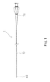
- FIG. 1 is an explanatory diagram illustrating a structure of a catheter 1 according to a first embodiment of the invention.
- the catheter 1 of the first embodiment is constituted by a catheter shaft 10, a tip 60 provided at the distal end of the catheter shaft 10, and a connector 70 provided at the proximal end of the catheter shaft 10, for example.
- FIG. 2 is an explanatory diagram illustrating the detail of the catheter shaft 10 of the catheter 1 according to the first embodiment of the invention.
- the catheter shaft 10 of the first embodiment is a tubular structural body, and is constituted by an inner layer 20, a coil body 30 as a reinforcing layer covering the inner layer 20, and an outer layer 50 covering the coil body 30, for example.
- the inner layer 20 is formed of resin.
- the resin material forming the inner layer 20 is not especially limited. However, considering slidability with an inserted instrument (a guide wire or a catheter, for example), polytetrafluoroethylene (PTFE) is preferable.
- PTFE polytetrafluoroethylene
- the outer layer 50 is also formed of resin.
- the resin material forming the outer layer 50 is not especially limited, and there can be used polyamide, polyamide elastomer, polyester, and polyurethane, for example.
- the coil body 30 is formed by winding two kinds of single-strand wires having different wire diameters (small-diameter or thin wires 41, large-diameter or thick wires 42) into a helical coil structure.
- the material of single-strand wires constituting the coil body 30 is not especially limited, and there can be used stainless steel (SUS304, SUS316, etc.), gold, white gold, tungsten, platinum, nickel, and an alloy of such elements, for example.
- the resin tip 60 is provided at the distal end of the catheter shaft 10.
- the resin forming the tip 60 is not especially limited. However, polyurethane, polyurethane elastomer, etc. are used preferably.
- the tip 60 may contain radiopaque powder (tungsten powder, for example). This enables a technician such as a physician to accurately grasp a position of the catheter in coronary angiography.
- the thick wires 42 of the coil body 30 are ground so that the cross-sectional shape thereis is formed to have a substantially semicircular shape. Then, the grinding of the thick wires 42 makes the inner diameter ID and the outer diameter OD of the coil body 30 constant.
- the thick wires 42 are ground so that the cross-sectional shape thereof is formed to have a substantially semicircular shape, i.e. to have the shape of a circular segment, whereby the inner diameter ID and the outer diameter OD of the coil body 30 become constant, and no unevenness occurs on the outer surface (or the inner surface) of the coil body 30. Therefore, it is possible to prevent increase of sliding resistance between the outer surface of the catheter 1 and an inner wall of a blood vessel or a lesion, for example, and an increase of sliding resistance between the inner surface of the catheter 1 and a combined device such as a guide wire.
- FIG. 3 is an explanatory diagram illustrating a situation when the coil body 30 of the catheter 1 according to the first embodiment of the invention is bent.
- force is added to the element wires on the bent side (the lower side in FIG. 3 ) in a direction compressing the coil body 30.
- the thin wires 41 adjacent to the thick wires 42 slightly move to the lumen side of the coil body 30 as the thin wires 41 are pushed out along the circular arc portion of the thick wires 42.
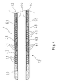
- FIG. 4 is an explanatory diagram illustrating the detail of a catheter shaft 12 of a catheter 2 according to a second embodiment of the invention.
- the illustrated catheter 2 of the second embodiment is different from the catheter 1 of the above-described first embodiment in the following aspect. That is, in the catheter 1 of the first embodiment, the straight portion of the substantially semicircular shape of the thick wires 42 is disposed on the outer side of the coil body 30 (see FIG. 2 ). By contrast, in the catheter 2 of the second embodiment, the straight portion of the semicircular shape of the thick wires 43 is disposed on the inner side of a coil body 32, as illustrated in FIG. 4 .
- the catheter 1 of the first embodiment and the catheter 2 of the second embodiment have the same structure. That is, the catheter shaft 12 is constituted by the inner layer 20, the coil body 32 covering the inner layer 20, and an outer layer 52 covering the coil body 32, and the coil body 32 is constituted by the thin wires 41 and the thick wires 43. Moreover, the tip 60 is provided at the distal end of the catheter shaft 12.
- the catheter 1 of above-described first embodiment can be produced more easily. That is, this is because, in the catheter 1 of the first embodiment, the straight portion of the substantially semicircular shape of the thick wires 42 is disposed on the outer side of the coil body 30 (see FIG. 2 ), and thus it is possible to easily produce the coil body 30 only by forming the coil body by wiring the thick wires 42 and the thin wires 41 into a helical coil structure and then grinding the thick wires 42 from the outer side of the coil body.
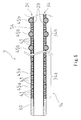
- FIG. 5 is an explanatory diagram illustrating the detail of a catheter shaft 14 of a catheter 3 according to a third embodiment of the invention.
- the illustrated catheter 3 of the third embodiment is different from the catheter 1 of the above-described first embodiment in the following aspect. That is, in the catheter 3, thick wires 45a are ground at a distal end portion 34a, i.e. at a length part, of a coil body 34 so that the cross-sectional shape thereof is formed to have a substantially semicircular shape, while thick wires 45b are not ground at a proximal end portion 34b, i.e. at another length part, of the coil body 34. Then, in the length part in which the thick wires 45b are not ground, the thick wires 45b project on the outer side of the coil body 34, thus forming unevenness on the outer surface.
- the catheter 3 of the third embodiment has the same structure as the catheter 1 of the above-described first embodiment. That is, the catheter shaft 14 is constituted by the inner layer 20, the coil body 34 covering the inner layer 20, and an outer layer 54 covering the coil body 34, and the coil body 34 is constituted by the thin wires 41 and the thick wires 45. Moreover, the tip 60 is provided at the distal end of the catheter shaft 14.
- the catheter 3 of the third embodiment can exert, at the distal end portion of the catheter 3 inserted in a curved peripheral blood vessel, favorable sliding properties relative to an inner wall of a blood vessel and favorable following properties for a blood vessel.
- the thick wires 45b are not ground at the proximal end portion of the catheter 3, and thus unevenness is formed on the outer peripheral surface of the coil body 34. This moderately secures sliding resistance at the proximal end portion of the catheter 3, which makes it possible to easily fix the catheter 3 inserted in a lumen of a blood vessel, etc. at a desired position.
- FIG. 6 is an explanatory diagram illustrating the detail of a catheter shaft 16 of a catheter 4 according to a fourth embodiment of the invention.
- the inner layer 20 is covered by a braid layer 80 formed by braiding metal wires, and the braid layer 80 is covered by a coil body 36. Then, the coil body 36 is covered by an outer layer 56.
- the catheter 4 of the fourth embodiment has the same structure as the catheter 3 of the above-described third embodiment. That is, the coil body 36 is constituted by the thin wires 41 and the thick wires 45, and the thick wires 45 are ground at a distal end portion 36a of the coil body 36 (the thick wires 45a) and are not ground at a proximal end portion 36b of the coil body 36 (the thick wires 45b). Moreover, the tip 60 is provided at the distal end of the catheter shaft 16.
- the braid layer 80 is provided as a reinforcing layer of the catheter 4 in addition to the coil body 36, which increases the rigidity of the catheter shaft 16.
- the rigidity reduced by grinding of the thick wires 45 can be compensated by the braid layer 80. As a result, it is possible to easily transmit push-in force added by a technician in a distal end direction to the tip 60.
Landscapes
- Health & Medical Sciences (AREA)
- Life Sciences & Earth Sciences (AREA)
- Biophysics (AREA)
- Pulmonology (AREA)
- Engineering & Computer Science (AREA)
- Anesthesiology (AREA)
- Biomedical Technology (AREA)
- Heart & Thoracic Surgery (AREA)
- Hematology (AREA)
- Animal Behavior & Ethology (AREA)
- General Health & Medical Sciences (AREA)
- Public Health (AREA)
- Veterinary Medicine (AREA)
- Media Introduction/Drainage Providing Device (AREA)
- Materials For Medical Uses (AREA)
Abstract
Description
- The present invention relates to a catheter inserted in a blood vessel, etc. for use.
- There is known a catheter inserted in a lumen of a blood vessel, etc. for use. With the use of a catheter, a physician injects liquid chemicals or a contrast agent into a blood vessel or sends various devices (a stent or an embolic coil, for example) to a lesion of a blood vessel.
- The catheter is constituted by a resin tube and various reinforcing bodies reinforcing the tube. For example, European Unexamined Patent Application No.
1120127 describes that a coil body formed by winding a plurality of single-strand wires into a helical coil structure is used as a reinforcing body of a catheter. Moreover, there is proposed a technique of improving rotation transmission performance and press-in performance (pushability) of a catheter by using, as some of a plurality of single-strand wires constituting the coil body, thicker element wires (thick wires) than other element wires (thin wires) (U.S. Unexamined Patent Application No. 2007/0208368 , for example). - However, the conventional catheter described above has a problem of unevenness occurring on an outer peripheral surface or an inner peripheral surface of the coil body because the thin wires and the thick wires constitute the coil body. This consequently causes a problem of increasing sliding resistance between the outer peripheral surface of the catheter and an inner wall of a blood vessel or a lesion, for example, or increasing sliding resistance between the inner peripheral surface of the catheter and a combined device such as a guide wire. Moreover, the occurrence of unevenness on the outer peripheral surface (or the inner peripheral surface) of the catheter makes it difficult, when covering the outer peripheral surface (or the inner peripheral surface) of the catheter with coating, to sufficiently adhere the coating.
- In view of the above problems of the conventional technique, the present invention aims at preventing occurrence of unevenness on an outer peripheral surface or an inner peripheral surface of a catheter including a coil body constituted by large-diameter or thick wires and small-diameter or thin wires.
- In order to solve the problems described above, the catheter of the invention adopts the following structure. That is, the catheter includes a tube body including an inner layer, a reinforcing layer covering the inner layer, and an outer layer covering the reinforcing layer. The tube body may form a catheter shaft extending from a proximal end to a distal end. The reinforcing layer is a coil body formed by winding a plurality of single-strand wires comprising small-diameter or thin wires and large-diameter or thick wires into a helical coil structure. The coil body includes a length part in which the thick wires are ground so that the cross-sectional shape of the thick wires is formed to have a substantially semicircular shape, i.e. to have the shape of a circular segment, and an inner diameter and an outer diameter of the coil body are constant in the part in which the thick wires are ground.
- Such a catheter of the invention includes a length part in which the thick wires are ground so that the cross-sectional shape thereof is formed to have a substantially semicircular shape, and an inner diameter and an outer diameter of the coil body in this part are constant. Thus, no unevenness occurs on the outer surface (or the inner surface) of the coil body. Therefore, it is possible to suppress sliding resistance on the surfaces of the catheter and secure adhesion of coating.
- Moreover, as described in detail later, in the catheter of the invention, when the catheter is bent, the thin wires move along the circular arc portion of the thick wires, which allows the catheter to bend largely. As a result, it is possible to exert favorable following properties even for a largely bent blood vessel.
- Moreover, in the catheter of the invention described above, a straight portion of the substantially semicircular shape of the thick wires may be disposed on the inner side of the coil body or on the outer side of the coil body.
- In such a catheter of the invention, if the straight portion of the section (substantially semicircular shape) of the thick wires is disposed on the outer side of the coil body, it is possible to easily produce the catheter of the invention only by forming the coil body by wiring thick wires and thin wires and then grinding the thick wires from the outer side of the coil body.
- Moreover, in the catheter of the invention described above, the coil body has a proximal end and a distal end, wherein the length part in which the thick wires are ground may be provided at a distal end portion of the coil body, and another length part of the coil body, in which the thick wires are not ground may be provided at a proximal end portion of the coil body. In the length part in which the thick wires are not ground, the thick wires may project on the outer side of the coil body.
- In such a catheter of the invention, the length part in which the thick wires are ground (a length part with a smooth surface) is provided at the distal end portion of the coil body, and the other length part in which the thick wires are not ground and project on the outer peripheral side (a length part with an uneven surface) is provided at the proximal end portion of the coil body. Therefore, it is possible to easily fix the catheter at a desired position by suppressing sliding resistance at the distal end portion of the catheter particularly requiring sliding properties and moderately securing sliding resistance at the proximal end of the catheter, in addition to the effects of the invention described above.
- Moreover, in the catheter of the invention described above, a braid layer may be disposed between the inner layer and the coil body to increase a rigidity of the tube body.
-
-
FIG. 1 is an explanatory diagram illustrating a structure of a catheter according to a first embodiment of the invention; -
FIG. 2 is an explanatory diagram illustrating the detail of a catheter shaft of the catheter according to the first embodiment of the invention; -
FIG. 3 is an explanatory diagram illustrating a situation when a coil body of the catheter according to the first embodiment of the invention is bent; -
FIG. 4 is an explanatory diagram illustrating the detail of a catheter shaft of a catheter according to a second embodiment of the invention; -
FIG. 5 is an explanatory diagram illustrating the detail of a catheter shaft of a catheter according to a third embodiment of the invention; and -
FIG. 6 is an explanatory diagram illustrating the detail of a catheter shaft of a catheter according to a fourth embodiment of the invention. - In the following, various embodiments of the catheter of the invention will be described so as to clarify the subject matter of the above-described invention.
-
FIG. 1 is an explanatory diagram illustrating a structure of a catheter 1 according to a first embodiment of the invention. As illustrated inFIG. 1 , the catheter 1 of the first embodiment is constituted by acatheter shaft 10, atip 60 provided at the distal end of thecatheter shaft 10, and aconnector 70 provided at the proximal end of thecatheter shaft 10, for example. - Note that the "catheter shaft" in the specification corresponds to the "tube body" of the invention.
-
FIG. 2 is an explanatory diagram illustrating the detail of thecatheter shaft 10 of the catheter 1 according to the first embodiment of the invention. As illustrated inFIG. 2 , thecatheter shaft 10 of the first embodiment is a tubular structural body, and is constituted by aninner layer 20, acoil body 30 as a reinforcing layer covering theinner layer 20, and anouter layer 50 covering thecoil body 30, for example. - The
inner layer 20 is formed of resin. The resin material forming theinner layer 20 is not especially limited. However, considering slidability with an inserted instrument (a guide wire or a catheter, for example), polytetrafluoroethylene (PTFE) is preferable. - The
outer layer 50 is also formed of resin. The resin material forming theouter layer 50 is not especially limited, and there can be used polyamide, polyamide elastomer, polyester, and polyurethane, for example. - The
coil body 30 is formed by winding two kinds of single-strand wires having different wire diameters (small-diameter orthin wires 41, large-diameter or thick wires 42) into a helical coil structure. - Note that the material of single-strand wires constituting the
coil body 30 is not especially limited, and there can be used stainless steel (SUS304, SUS316, etc.), gold, white gold, tungsten, platinum, nickel, and an alloy of such elements, for example. - The
resin tip 60 is provided at the distal end of thecatheter shaft 10. The resin forming thetip 60 is not especially limited. However, polyurethane, polyurethane elastomer, etc. are used preferably. Moreover, thetip 60 may contain radiopaque powder (tungsten powder, for example). This enables a technician such as a physician to accurately grasp a position of the catheter in coronary angiography. - Here, in the catheter 1 of the first embodiment, the
thick wires 42 of thecoil body 30 are ground so that the cross-sectional shape thereis is formed to have a substantially semicircular shape. Then, the grinding of thethick wires 42 makes the inner diameter ID and the outer diameter OD of thecoil body 30 constant. - In such a catheter 1 of the first embodiment, the
thick wires 42 are ground so that the cross-sectional shape thereof is formed to have a substantially semicircular shape, i.e. to have the shape of a circular segment, whereby the inner diameter ID and the outer diameter OD of thecoil body 30 become constant, and no unevenness occurs on the outer surface (or the inner surface) of thecoil body 30. Therefore, it is possible to prevent increase of sliding resistance between the outer surface of the catheter 1 and an inner wall of a blood vessel or a lesion, for example, and an increase of sliding resistance between the inner surface of the catheter 1 and a combined device such as a guide wire. - Moreover, no unevenness occurs on the surface of the
coil body 30, which makes it possible to sufficiently secure adhesion of coating (theouter layer 50 in the first embodiment) on thecoil body 30. -
FIG. 3 is an explanatory diagram illustrating a situation when thecoil body 30 of the catheter 1 according to the first embodiment of the invention is bent. When thecoil body 30 is bent, force is added to the element wires on the bent side (the lower side inFIG. 3 ) in a direction compressing thecoil body 30. Here, as illustrated by white arrows inFIG. 3 , thethin wires 41 adjacent to thethick wires 42 slightly move to the lumen side of thecoil body 30 as thethin wires 41 are pushed out along the circular arc portion of thethick wires 42. - In this manner, when the
coil body 30 is bent, thethin wires 41 move along the circular arc portion of thethick wires 42, which prevents stretching of thecoil body 30 and allows the coil body 30 (and then the catheter 1) to bend largely. As a result, it is possible to exert favorable following properties even for a largely bent blood vessel. -
FIG. 4 is an explanatory diagram illustrating the detail of acatheter shaft 12 of a catheter 2 according to a second embodiment of the invention. The illustrated catheter 2 of the second embodiment is different from the catheter 1 of the above-described first embodiment in the following aspect. That is, in the catheter 1 of the first embodiment, the straight portion of the substantially semicircular shape of thethick wires 42 is disposed on the outer side of the coil body 30 (seeFIG. 2 ). By contrast, in the catheter 2 of the second embodiment, the straight portion of the semicircular shape of thethick wires 43 is disposed on the inner side of acoil body 32, as illustrated inFIG. 4 . - Regarding aspects other than the above, the catheter 1 of the first embodiment and the catheter 2 of the second embodiment have the same structure. That is, the
catheter shaft 12 is constituted by theinner layer 20, thecoil body 32 covering theinner layer 20, and anouter layer 52 covering thecoil body 32, and thecoil body 32 is constituted by thethin wires 41 and thethick wires 43. Moreover, thetip 60 is provided at the distal end of thecatheter shaft 12. - Also in such a catheter 2 of the second embodiment, it is possible to prevent occurrence of unevenness on the surface of the coil body 32 (and then the catheter 2), similarly to the catheter 1 of the above-described first embodiment. Moreover, when the
coil body 32 is bent, thethin wires 41 move along the circular arc portion of thethick wires 43, which enables the catheter 2 to bend largely. - In fact, the catheter 1 of above-described first embodiment can be produced more easily. That is, this is because, in the catheter 1 of the first embodiment, the straight portion of the substantially semicircular shape of the
thick wires 42 is disposed on the outer side of the coil body 30 (seeFIG. 2 ), and thus it is possible to easily produce thecoil body 30 only by forming the coil body by wiring thethick wires 42 and thethin wires 41 into a helical coil structure and then grinding thethick wires 42 from the outer side of the coil body. -
FIG. 5 is an explanatory diagram illustrating the detail of acatheter shaft 14 of acatheter 3 according to a third embodiment of the invention. The illustratedcatheter 3 of the third embodiment is different from the catheter 1 of the above-described first embodiment in the following aspect. That is, in thecatheter 3,thick wires 45a are ground at adistal end portion 34a, i.e. at a length part, of acoil body 34 so that the cross-sectional shape thereof is formed to have a substantially semicircular shape, whilethick wires 45b are not ground at aproximal end portion 34b, i.e. at another length part, of thecoil body 34. Then, in the length part in which thethick wires 45b are not ground, thethick wires 45b project on the outer side of thecoil body 34, thus forming unevenness on the outer surface. - Regarding aspects other than the above, the
catheter 3 of the third embodiment has the same structure as the catheter 1 of the above-described first embodiment. That is, thecatheter shaft 14 is constituted by theinner layer 20, thecoil body 34 covering theinner layer 20, and anouter layer 54 covering thecoil body 34, and thecoil body 34 is constituted by thethin wires 41 and the thick wires 45. Moreover, thetip 60 is provided at the distal end of thecatheter shaft 14. - Also in such a
catheter 3 of the third embodiment, it is possible to prevent occurrence of unevenness on the surface of thedistal end portion 34a of the coil body 34 (and then the catheter 3), similarly to the catheters of the above-described various embodiments. Moreover, when thedistal end portion 34a of thecoil body 34 is bent, thethin wires 41 move along the circular arc portion of thethick wires 45a, which allows thecatheter 3 to bend largely. In this manner, thecatheter 3 of the third embodiment can exert, at the distal end portion of thecatheter 3 inserted in a curved peripheral blood vessel, favorable sliding properties relative to an inner wall of a blood vessel and favorable following properties for a blood vessel. - Meanwhile, in the
catheter 3 of the third embodiment, thethick wires 45b are not ground at the proximal end portion of thecatheter 3, and thus unevenness is formed on the outer peripheral surface of thecoil body 34. This moderately secures sliding resistance at the proximal end portion of thecatheter 3, which makes it possible to easily fix thecatheter 3 inserted in a lumen of a blood vessel, etc. at a desired position. -
FIG. 6 is an explanatory diagram illustrating the detail of acatheter shaft 16 of acatheter 4 according to a fourth embodiment of the invention. In thecatheter 4 of the fourth embodiment, theinner layer 20 is covered by abraid layer 80 formed by braiding metal wires, and thebraid layer 80 is covered by acoil body 36. Then, thecoil body 36 is covered by anouter layer 56. - Regarding aspects other than the above, the
catheter 4 of the fourth embodiment has the same structure as thecatheter 3 of the above-described third embodiment. That is, thecoil body 36 is constituted by thethin wires 41 and the thick wires 45, and the thick wires 45 are ground at adistal end portion 36a of the coil body 36 (thethick wires 45a) and are not ground at aproximal end portion 36b of the coil body 36 (thethick wires 45b). Moreover, thetip 60 is provided at the distal end of thecatheter shaft 16. - Also in such a
catheter 4 of the fourth embodiment, it is possible to prevent occurrence of unevenness on the surface of thedistal end portion 36a of the coil body 36 (and then the catheter 4), and allow thedistal end portion 36a of thecoil body 36 to bend largely, similarly to the catheters of the above-described various embodiments. - Furthermore, in the
catheter 4 of the fourth embodiment, thebraid layer 80 is provided as a reinforcing layer of thecatheter 4 in addition to thecoil body 36, which increases the rigidity of thecatheter shaft 16. In particular, at thedistal end portion 36a of thecoil body 36, the rigidity reduced by grinding of the thick wires 45 can be compensated by thebraid layer 80. As a result, it is possible to easily transmit push-in force added by a technician in a distal end direction to thetip 60.
Claims (6)
- A catheter (1; 2; 3; 4), comprising:a tube body (10) including an inner layer (20), a reinforcing layer covering the inner layer (20), and an outer layer (50) covering the reinforcing layer, wherein
the reinforcing layer is a coil body (30; 32) formed by winding a plurality of single-strand wires comprising thin wires (41) and thick wires (42; 43; 45a) into a helical coil structure, characterized in thatthe coil body (30; 32) includes a length part in which the thick wires (42; 43; 45a) are ground so that the cross-sectional shape of the thick wires (42; 43; 45a) is formed to have a substantially semicircular shape, andan inner diameter (ID) and an outer diameter (OD) of the coil body (30; 32) are constant in the part in which the thick wires (42; 43; 45a) are ground. - The catheter (1; 3; 4) according to claim 1, wherein
a straight portion of the substantially semicircular shape of the thick wires (42; 45a) is disposed on an outer side of the coil body (30). - The catheter (2) according to claim 1, wherein
a straight portion of the substantially semicircular shape of the thick wires (43) is disposed on an inner side of the coil body (32). - The catheter (3; 4) according to any one of claims 1 to 3, wherein
the coil body (34; 36) has a proximal end and a distal end,
the length part in which the thick wires (45a) are ground is at a distal end portion of the coil body (34; 36), and
the coil body (34; 36) further has a length part in which the thick wires (45b) are not ground, at its proximal end portion. - The catheter (3; 4) according to claim 4, wherein
the thick wires (45b) project on the outer side of the coil body (34; 36) in the length part in which the thick wires (45b) are not ground. - The catheter (4) according to any one of claims 1 to 5, wherein
a braid layer (80) is disposed between the inner layer (20) and the coil body (36).
Applications Claiming Priority (1)
| Application Number | Priority Date | Filing Date | Title |
|---|---|---|---|
| JP2014104918A JP6344762B2 (en) | 2014-05-21 | 2014-05-21 | catheter |
Publications (2)
| Publication Number | Publication Date |
|---|---|
| EP2949358A1 true EP2949358A1 (en) | 2015-12-02 |
| EP2949358B1 EP2949358B1 (en) | 2017-05-31 |
Family
ID=53008285
Family Applications (1)
| Application Number | Title | Priority Date | Filing Date |
|---|---|---|---|
| EP15163480.5A Active EP2949358B1 (en) | 2014-05-21 | 2015-04-14 | Catheter |
Country Status (4)
| Country | Link |
|---|---|
| US (1) | US9597481B2 (en) |
| EP (1) | EP2949358B1 (en) |
| JP (1) | JP6344762B2 (en) |
| CN (1) | CN105079939B (en) |
Families Citing this family (44)
| Publication number | Priority date | Publication date | Assignee | Title |
|---|---|---|---|---|
| US9265512B2 (en) | 2013-12-23 | 2016-02-23 | Silk Road Medical, Inc. | Transcarotid neurovascular catheter |
| US11065019B1 (en) | 2015-02-04 | 2021-07-20 | Route 92 Medical, Inc. | Aspiration catheter systems and methods of use |
| CA2983072A1 (en) | 2015-02-04 | 2016-08-11 | Route 92 Medical, Inc. | Rapid aspiration thrombectomy system and method |
| WO2017019563A1 (en) | 2015-07-24 | 2017-02-02 | Route 92 Medical, Inc. | Anchoring delivery system and methods |
| US20170028167A1 (en) | 2015-07-30 | 2017-02-02 | Jeffrey M. Welch | Coronary guide catheter |
| US10716915B2 (en) | 2015-11-23 | 2020-07-21 | Mivi Neuroscience, Inc. | Catheter systems for applying effective suction in remote vessels and thrombectomy procedures facilitated by catheter systems |
| JP7012655B2 (en) | 2016-02-24 | 2022-01-28 | インセプト、リミテッド、ライアビリティ、カンパニー | Flexible enhanced neurovascular catheter |
| EP4032578A1 (en) | 2016-07-13 | 2022-07-27 | Perfuze Limited | High flexibility, kink resistant catheter shaft |
| EP3508246B1 (en) * | 2016-09-05 | 2021-08-11 | Asahi Intecc Co., Ltd. | Guide wire |
| DK3551271T3 (en) | 2016-12-08 | 2023-10-02 | Abiomed Inc | OVERMOLDING TECHNIQUE FOR DESIGNING PEEL-AWAY INTRODUCING |
| EP3565511B1 (en) | 2017-01-06 | 2023-10-18 | Incept, LLC | Thromboresistant coatings for aneurysm treatment devices |
| EP4134120A1 (en) | 2017-01-10 | 2023-02-15 | Route 92 Medical, Inc. | Aspiration catheter systems |
| US10864350B2 (en) | 2017-01-20 | 2020-12-15 | Route 92 Medical, Inc. | Single operator intracranial medical device delivery systems and methods of use |
| CN110312542B (en) * | 2017-03-10 | 2022-03-18 | 朝日英达科株式会社 | Probe needle |
| IL301505B2 (en) | 2017-11-06 | 2024-08-01 | Abiomed Inc | Peel away hemostasis valve |
| CN111465420B (en) | 2017-12-15 | 2023-04-18 | 佩尔福兹有限公司 | Improved catheter and apparatus and system incorporating same |
| EP3787523A4 (en) | 2018-05-01 | 2022-02-23 | Incept, LLC | DEVICES AND METHODS FOR REMOVING OBSTRUCTIVE MATERIAL FROM AN INTRAVASCULAR SITE |
| US11395665B2 (en) | 2018-05-01 | 2022-07-26 | Incept, Llc | Devices and methods for removing obstructive material, from an intravascular site |
| SG11202011175QA (en) | 2018-05-16 | 2020-12-30 | Abiomed Inc | Peel-away sheath assembly |
| CN115999019B (en) | 2018-05-17 | 2025-05-27 | 92号医疗公司 | Aspiration catheter system and method of use |
| US10953195B2 (en) | 2018-06-01 | 2021-03-23 | Covidien Lp | Flexible tip catheter |
| US11471582B2 (en) | 2018-07-06 | 2022-10-18 | Incept, Llc | Vacuum transfer tool for extendable catheter |
| WO2020010310A1 (en) | 2018-07-06 | 2020-01-09 | Imperative Care, Inc. | Sealed neurovascular extendable catheter |
| JP7089994B2 (en) * | 2018-09-05 | 2022-06-23 | 朝日インテック株式会社 | Tubular body |
| EP3866897A4 (en) * | 2018-10-15 | 2022-08-03 | ResMed Pty Ltd | WIRE HEATED TUBE FOR BREATHING APPARATUS |
| JP7279466B2 (en) * | 2019-03-28 | 2023-05-23 | 住友ベークライト株式会社 | catheter |
| US11766539B2 (en) | 2019-03-29 | 2023-09-26 | Incept, Llc | Enhanced flexibility neurovascular catheter |
| EP3967356A4 (en) * | 2019-05-07 | 2023-06-07 | Asahi Intecc Co., Ltd. | Guide wire |
| WO2021076642A1 (en) | 2019-10-15 | 2021-04-22 | Imperative Care, Inc. | Systems and methods for multivariate stroke detection |
| KR20220071259A (en) * | 2019-11-08 | 2022-05-31 | 아사히 인텍크 가부시키가이샤 | catheter |
| EP4076611A4 (en) | 2019-12-18 | 2023-11-15 | Imperative Care, Inc. | METHODS AND SYSTEMS FOR TREATING VENOUS THROMBOEMBOLIC DISEASES |
| US20230248498A1 (en) | 2019-12-18 | 2023-08-10 | Imperative Care, Inc. | Manually rotatable thrombus engagement tool |
| US11439799B2 (en) | 2019-12-18 | 2022-09-13 | Imperative Care, Inc. | Split dilator aspiration system |
| US11638637B2 (en) | 2019-12-18 | 2023-05-02 | Imperative Care, Inc. | Method of removing embolic material with thrombus engagement tool |
| JP7398293B2 (en) * | 2020-02-13 | 2023-12-14 | 日本発條株式会社 | Endoscope insert and endoscope using the same |
| CN118925025A (en) | 2020-03-10 | 2024-11-12 | 因普瑞缇夫护理公司 | Neurovascular catheters with enhanced flexibility |
| US11207497B1 (en) | 2020-08-11 | 2021-12-28 | Imperative Care, Inc. | Catheter with enhanced tensile strength |
| US12582802B2 (en) | 2020-10-09 | 2026-03-24 | Route 92 Medical, Inc. | Aspiration catheter systems and methods of use |
| CN113208709B (en) * | 2021-07-08 | 2021-11-02 | 上海介入医疗器械有限公司 | Visualization-enhanced puncture sheath and puncture assembly |
| US12558175B2 (en) | 2021-08-12 | 2026-02-24 | Imperative Care, Inc. | Multi catheter method of performing a robotic neurovascular procedure |
| USD1077996S1 (en) | 2021-10-18 | 2025-06-03 | Imperative Care, Inc. | Inline fluid filter |
| JP7693567B2 (en) * | 2022-01-25 | 2025-06-17 | 朝日インテック株式会社 | Coil body |
| CN115462832A (en) * | 2022-10-24 | 2022-12-13 | 苏州冰晶智能医疗科技有限公司 | Ultrasonic catheters and processing methods |
| US12171917B1 (en) | 2024-01-08 | 2024-12-24 | Imperative Care, Inc. | Devices for blood capture and reintroduction during aspiration procedure |
Citations (6)
| Publication number | Priority date | Publication date | Assignee | Title |
|---|---|---|---|---|
| EP1120127A1 (en) | 2000-01-28 | 2001-08-01 | William Cook Europe A/S | Catheter made of a multifilar row of wires |
| US20070208368A1 (en) | 2006-02-13 | 2007-09-06 | Osamu Katoh | Recanalizing occluded vessels using controlled antegrade and retrograde tracking |
| JP2007236472A (en) * | 2006-03-06 | 2007-09-20 | Terumo Corp | Catheter |
| US20090281610A1 (en) * | 2008-05-07 | 2009-11-12 | Cook Incorporated | Delivery system with low longitudinal compressibility |
| EP2174685A1 (en) * | 2008-10-11 | 2010-04-14 | Asahi Intecc Co., Ltd. | Catheter |
| US20110245775A1 (en) * | 2010-04-01 | 2011-10-06 | Cook Incorporated | Tapered sheath |
Family Cites Families (14)
| Publication number | Priority date | Publication date | Assignee | Title |
|---|---|---|---|---|
| US6673025B1 (en) * | 1993-12-01 | 2004-01-06 | Advanced Cardiovascular Systems, Inc. | Polymer coated guidewire |
| US6142975A (en) * | 1998-12-31 | 2000-11-07 | Advanced Cardiovascular Systems, Inc. | Guidewire having braided wire over drawn tube construction |
| US20040082879A1 (en) * | 2000-01-28 | 2004-04-29 | Klint Henrik S. | Endovascular medical device with plurality of wires |
| CA2397697C (en) * | 2000-01-28 | 2008-04-15 | William Cook, Europe Aps | Endovascular medical device with plurality of wires |
| US8113916B2 (en) * | 2003-01-17 | 2012-02-14 | Boston Scientific Scimed, Inc. | Straightening and centerless grinding of wire for use with medical devices |
| US8382739B2 (en) * | 2003-12-02 | 2013-02-26 | Boston Scientific Scimed, Inc. | Composite medical device and method of forming |
| CN1689657B (en) * | 2004-04-28 | 2010-09-22 | 加藤修 | Hollow tube applied for medical instrument and conduit containing the same |
| JP4693091B2 (en) * | 2004-12-21 | 2011-06-01 | 朝日インテック株式会社 | Catheter and manufacturing method thereof |
| JP2011110144A (en) * | 2009-11-25 | 2011-06-09 | Sumitomo Bakelite Co Ltd | Catheter for intravascular treatment |
| JP4931260B2 (en) * | 2009-12-10 | 2012-05-16 | 朝日インテック株式会社 | Guide wire |
| JP2012061070A (en) * | 2010-09-15 | 2012-03-29 | Sumitomo Bakelite Co Ltd | Catheter |
| JP2013039305A (en) * | 2011-08-19 | 2013-02-28 | Asahi Intecc Co Ltd | Guidewire |
| CN103721337B (en) * | 2012-10-16 | 2017-02-22 | 上海微创医疗器械(集团)有限公司 | Catheter pushed into blood vessel in cooperation with guide wire and manufacturing method thereof |
| JP5901078B2 (en) * | 2014-03-25 | 2016-04-06 | 朝日インテック株式会社 | catheter |
-
2014
- 2014-05-21 JP JP2014104918A patent/JP6344762B2/en active Active
-
2015
- 2015-02-26 CN CN201510088160.0A patent/CN105079939B/en active Active
- 2015-04-14 EP EP15163480.5A patent/EP2949358B1/en active Active
- 2015-05-13 US US14/711,114 patent/US9597481B2/en active Active
Patent Citations (6)
| Publication number | Priority date | Publication date | Assignee | Title |
|---|---|---|---|---|
| EP1120127A1 (en) | 2000-01-28 | 2001-08-01 | William Cook Europe A/S | Catheter made of a multifilar row of wires |
| US20070208368A1 (en) | 2006-02-13 | 2007-09-06 | Osamu Katoh | Recanalizing occluded vessels using controlled antegrade and retrograde tracking |
| JP2007236472A (en) * | 2006-03-06 | 2007-09-20 | Terumo Corp | Catheter |
| US20090281610A1 (en) * | 2008-05-07 | 2009-11-12 | Cook Incorporated | Delivery system with low longitudinal compressibility |
| EP2174685A1 (en) * | 2008-10-11 | 2010-04-14 | Asahi Intecc Co., Ltd. | Catheter |
| US20110245775A1 (en) * | 2010-04-01 | 2011-10-06 | Cook Incorporated | Tapered sheath |
Also Published As
| Publication number | Publication date |
|---|---|
| CN105079939A (en) | 2015-11-25 |
| EP2949358B1 (en) | 2017-05-31 |
| JP6344762B2 (en) | 2018-06-20 |
| US9597481B2 (en) | 2017-03-21 |
| US20150335857A1 (en) | 2015-11-26 |
| CN105079939B (en) | 2021-05-25 |
| JP2015217237A (en) | 2015-12-07 |
Similar Documents
| Publication | Publication Date | Title |
|---|---|---|
| EP2949358B1 (en) | Catheter | |
| EP2937108B1 (en) | Catheter | |
| US12070558B2 (en) | Catheter shaft and associated devices, systems, and methods | |
| US10010698B2 (en) | Catheter | |
| EP3120890B1 (en) | Catheter | |
| EP3347079B1 (en) | Catheter | |
| US20170072163A1 (en) | Catheter shaft and associated devices, systems, and methods | |
| EP3347078B1 (en) | Polymeric catheter shaft with reinforcement | |
| EP2881136B1 (en) | Guidewire | |
| KR20120027116A (en) | Medical guide wire | |
| JP2007236472A (en) | Catheter | |
| JP2024500098A (en) | Medical catheter and its manufacturing method | |
| US11027094B2 (en) | Tubular body and catheter having tubular body | |
| JP4790349B2 (en) | catheter | |
| JP3179894U (en) | catheter | |
| JP6754270B2 (en) | Catheter assembly | |
| JP6685116B2 (en) | Catheter assembly | |
| JP6076855B2 (en) | Microcatheter and catheter apparatus | |
| JP6754271B2 (en) | Catheter assembly | |
| WO2018074074A1 (en) | Catheter assembly | |
| WO2023062983A1 (en) | Extension guide catheter | |
| JP2024162903A (en) | Medical Devices | |
| WO2015141280A1 (en) | Guide wire |
Legal Events
| Date | Code | Title | Description |
|---|---|---|---|
| AK | Designated contracting states |
Kind code of ref document: A1 Designated state(s): AL AT BE BG CH CY CZ DE DK EE ES FI FR GB GR HR HU IE IS IT LI LT LU LV MC MK MT NL NO PL PT RO RS SE SI SK SM TR |
|
| AX | Request for extension of the european patent |
Extension state: BA ME |
|
| PUAI | Public reference made under article 153(3) epc to a published international application that has entered the european phase |
Free format text: ORIGINAL CODE: 0009012 |
|
| 17P | Request for examination filed |
Effective date: 20160226 |
|
| RBV | Designated contracting states (corrected) |
Designated state(s): AL AT BE BG CH CY CZ DE DK EE ES FI FR GB GR HR HU IE IS IT LI LT LU LV MC MK MT NL NO PL PT RO RS SE SI SK SM TR |
|
| RIC1 | Information provided on ipc code assigned before grant |
Ipc: A61M 25/00 20060101AFI20160812BHEP |
|
| GRAP | Despatch of communication of intention to grant a patent |
Free format text: ORIGINAL CODE: EPIDOSNIGR1 |
|
| INTG | Intention to grant announced |
Effective date: 20161102 |
|
| GRAS | Grant fee paid |
Free format text: ORIGINAL CODE: EPIDOSNIGR3 |
|
| GRAA | (expected) grant |
Free format text: ORIGINAL CODE: 0009210 |
|
| AK | Designated contracting states |
Kind code of ref document: B1 Designated state(s): AL AT BE BG CH CY CZ DE DK EE ES FI FR GB GR HR HU IE IS IT LI LT LU LV MC MK MT NL NO PL PT RO RS SE SI SK SM TR |
|
| REG | Reference to a national code |
Ref country code: CH Ref legal event code: EP Ref country code: GB Ref legal event code: FG4D |
|
| REG | Reference to a national code |
Ref country code: AT Ref legal event code: REF Ref document number: 896874 Country of ref document: AT Kind code of ref document: T Effective date: 20170615 |
|
| REG | Reference to a national code |
Ref country code: IE Ref legal event code: FG4D |
|
| REG | Reference to a national code |
Ref country code: DE Ref legal event code: R096 Ref document number: 602015002875 Country of ref document: DE |
|
| REG | Reference to a national code |
Ref country code: NL Ref legal event code: MP Effective date: 20170531 |
|
| REG | Reference to a national code |
Ref country code: LT Ref legal event code: MG4D |
|
| REG | Reference to a national code |
Ref country code: AT Ref legal event code: MK05 Ref document number: 896874 Country of ref document: AT Kind code of ref document: T Effective date: 20170531 |
|
| PG25 | Lapsed in a contracting state [announced via postgrant information from national office to epo] |
Ref country code: LT Free format text: LAPSE BECAUSE OF FAILURE TO SUBMIT A TRANSLATION OF THE DESCRIPTION OR TO PAY THE FEE WITHIN THE PRESCRIBED TIME-LIMIT Effective date: 20170531 Ref country code: HR Free format text: LAPSE BECAUSE OF FAILURE TO SUBMIT A TRANSLATION OF THE DESCRIPTION OR TO PAY THE FEE WITHIN THE PRESCRIBED TIME-LIMIT Effective date: 20170531 Ref country code: AT Free format text: LAPSE BECAUSE OF FAILURE TO SUBMIT A TRANSLATION OF THE DESCRIPTION OR TO PAY THE FEE WITHIN THE PRESCRIBED TIME-LIMIT Effective date: 20170531 Ref country code: FI Free format text: LAPSE BECAUSE OF FAILURE TO SUBMIT A TRANSLATION OF THE DESCRIPTION OR TO PAY THE FEE WITHIN THE PRESCRIBED TIME-LIMIT Effective date: 20170531 Ref country code: GR Free format text: LAPSE BECAUSE OF FAILURE TO SUBMIT A TRANSLATION OF THE DESCRIPTION OR TO PAY THE FEE WITHIN THE PRESCRIBED TIME-LIMIT Effective date: 20170901 Ref country code: NO Free format text: LAPSE BECAUSE OF FAILURE TO SUBMIT A TRANSLATION OF THE DESCRIPTION OR TO PAY THE FEE WITHIN THE PRESCRIBED TIME-LIMIT Effective date: 20170831 Ref country code: ES Free format text: LAPSE BECAUSE OF FAILURE TO SUBMIT A TRANSLATION OF THE DESCRIPTION OR TO PAY THE FEE WITHIN THE PRESCRIBED TIME-LIMIT Effective date: 20170531 |
|
| PG25 | Lapsed in a contracting state [announced via postgrant information from national office to epo] |
Ref country code: LV Free format text: LAPSE BECAUSE OF FAILURE TO SUBMIT A TRANSLATION OF THE DESCRIPTION OR TO PAY THE FEE WITHIN THE PRESCRIBED TIME-LIMIT Effective date: 20170531 Ref country code: NL Free format text: LAPSE BECAUSE OF FAILURE TO SUBMIT A TRANSLATION OF THE DESCRIPTION OR TO PAY THE FEE WITHIN THE PRESCRIBED TIME-LIMIT Effective date: 20170531 Ref country code: SE Free format text: LAPSE BECAUSE OF FAILURE TO SUBMIT A TRANSLATION OF THE DESCRIPTION OR TO PAY THE FEE WITHIN THE PRESCRIBED TIME-LIMIT Effective date: 20170531 Ref country code: IS Free format text: LAPSE BECAUSE OF FAILURE TO SUBMIT A TRANSLATION OF THE DESCRIPTION OR TO PAY THE FEE WITHIN THE PRESCRIBED TIME-LIMIT Effective date: 20170930 Ref country code: RS Free format text: LAPSE BECAUSE OF FAILURE TO SUBMIT A TRANSLATION OF THE DESCRIPTION OR TO PAY THE FEE WITHIN THE PRESCRIBED TIME-LIMIT Effective date: 20170531 Ref country code: BG Free format text: LAPSE BECAUSE OF FAILURE TO SUBMIT A TRANSLATION OF THE DESCRIPTION OR TO PAY THE FEE WITHIN THE PRESCRIBED TIME-LIMIT Effective date: 20170831 |
|
| PG25 | Lapsed in a contracting state [announced via postgrant information from national office to epo] |
Ref country code: RO Free format text: LAPSE BECAUSE OF FAILURE TO SUBMIT A TRANSLATION OF THE DESCRIPTION OR TO PAY THE FEE WITHIN THE PRESCRIBED TIME-LIMIT Effective date: 20170531 Ref country code: EE Free format text: LAPSE BECAUSE OF FAILURE TO SUBMIT A TRANSLATION OF THE DESCRIPTION OR TO PAY THE FEE WITHIN THE PRESCRIBED TIME-LIMIT Effective date: 20170531 Ref country code: DK Free format text: LAPSE BECAUSE OF FAILURE TO SUBMIT A TRANSLATION OF THE DESCRIPTION OR TO PAY THE FEE WITHIN THE PRESCRIBED TIME-LIMIT Effective date: 20170531 Ref country code: SK Free format text: LAPSE BECAUSE OF FAILURE TO SUBMIT A TRANSLATION OF THE DESCRIPTION OR TO PAY THE FEE WITHIN THE PRESCRIBED TIME-LIMIT Effective date: 20170531 Ref country code: CZ Free format text: LAPSE BECAUSE OF FAILURE TO SUBMIT A TRANSLATION OF THE DESCRIPTION OR TO PAY THE FEE WITHIN THE PRESCRIBED TIME-LIMIT Effective date: 20170531 |
|
| PG25 | Lapsed in a contracting state [announced via postgrant information from national office to epo] |
Ref country code: PL Free format text: LAPSE BECAUSE OF FAILURE TO SUBMIT A TRANSLATION OF THE DESCRIPTION OR TO PAY THE FEE WITHIN THE PRESCRIBED TIME-LIMIT Effective date: 20170531 Ref country code: SM Free format text: LAPSE BECAUSE OF FAILURE TO SUBMIT A TRANSLATION OF THE DESCRIPTION OR TO PAY THE FEE WITHIN THE PRESCRIBED TIME-LIMIT Effective date: 20170531 Ref country code: IT Free format text: LAPSE BECAUSE OF FAILURE TO SUBMIT A TRANSLATION OF THE DESCRIPTION OR TO PAY THE FEE WITHIN THE PRESCRIBED TIME-LIMIT Effective date: 20170531 |
|
| REG | Reference to a national code |
Ref country code: DE Ref legal event code: R097 Ref document number: 602015002875 Country of ref document: DE |
|
| PLBE | No opposition filed within time limit |
Free format text: ORIGINAL CODE: 0009261 |
|
| STAA | Information on the status of an ep patent application or granted ep patent |
Free format text: STATUS: NO OPPOSITION FILED WITHIN TIME LIMIT |
|
| 26N | No opposition filed |
Effective date: 20180301 |
|
| PG25 | Lapsed in a contracting state [announced via postgrant information from national office to epo] |
Ref country code: SI Free format text: LAPSE BECAUSE OF FAILURE TO SUBMIT A TRANSLATION OF THE DESCRIPTION OR TO PAY THE FEE WITHIN THE PRESCRIBED TIME-LIMIT Effective date: 20170531 |
|
| PG25 | Lapsed in a contracting state [announced via postgrant information from national office to epo] |
Ref country code: MC Free format text: LAPSE BECAUSE OF FAILURE TO SUBMIT A TRANSLATION OF THE DESCRIPTION OR TO PAY THE FEE WITHIN THE PRESCRIBED TIME-LIMIT Effective date: 20170531 |
|
| REG | Reference to a national code |
Ref country code: CH Ref legal event code: PL |
|
| REG | Reference to a national code |
Ref country code: BE Ref legal event code: MM Effective date: 20180430 |
|
| REG | Reference to a national code |
Ref country code: IE Ref legal event code: MM4A |
|
| PG25 | Lapsed in a contracting state [announced via postgrant information from national office to epo] |
Ref country code: LU Free format text: LAPSE BECAUSE OF NON-PAYMENT OF DUE FEES Effective date: 20180414 |
|
| PG25 | Lapsed in a contracting state [announced via postgrant information from national office to epo] |
Ref country code: BE Free format text: LAPSE BECAUSE OF NON-PAYMENT OF DUE FEES Effective date: 20180430 Ref country code: CH Free format text: LAPSE BECAUSE OF NON-PAYMENT OF DUE FEES Effective date: 20180430 Ref country code: LI Free format text: LAPSE BECAUSE OF NON-PAYMENT OF DUE FEES Effective date: 20180430 |
|
| PG25 | Lapsed in a contracting state [announced via postgrant information from national office to epo] |
Ref country code: IE Free format text: LAPSE BECAUSE OF NON-PAYMENT OF DUE FEES Effective date: 20180414 Ref country code: FR Free format text: LAPSE BECAUSE OF NON-PAYMENT OF DUE FEES Effective date: 20180430 |
|
| PG25 | Lapsed in a contracting state [announced via postgrant information from national office to epo] |
Ref country code: MT Free format text: LAPSE BECAUSE OF NON-PAYMENT OF DUE FEES Effective date: 20180414 |
|
| PG25 | Lapsed in a contracting state [announced via postgrant information from national office to epo] |
Ref country code: TR Free format text: LAPSE BECAUSE OF FAILURE TO SUBMIT A TRANSLATION OF THE DESCRIPTION OR TO PAY THE FEE WITHIN THE PRESCRIBED TIME-LIMIT Effective date: 20170531 |
|
| PG25 | Lapsed in a contracting state [announced via postgrant information from national office to epo] |
Ref country code: PT Free format text: LAPSE BECAUSE OF FAILURE TO SUBMIT A TRANSLATION OF THE DESCRIPTION OR TO PAY THE FEE WITHIN THE PRESCRIBED TIME-LIMIT Effective date: 20170531 |
|
| PG25 | Lapsed in a contracting state [announced via postgrant information from national office to epo] |
Ref country code: CY Free format text: LAPSE BECAUSE OF FAILURE TO SUBMIT A TRANSLATION OF THE DESCRIPTION OR TO PAY THE FEE WITHIN THE PRESCRIBED TIME-LIMIT Effective date: 20170531 Ref country code: HU Free format text: LAPSE BECAUSE OF FAILURE TO SUBMIT A TRANSLATION OF THE DESCRIPTION OR TO PAY THE FEE WITHIN THE PRESCRIBED TIME-LIMIT; INVALID AB INITIO Effective date: 20150414 Ref country code: MK Free format text: LAPSE BECAUSE OF NON-PAYMENT OF DUE FEES Effective date: 20170531 |
|
| PG25 | Lapsed in a contracting state [announced via postgrant information from national office to epo] |
Ref country code: AL Free format text: LAPSE BECAUSE OF FAILURE TO SUBMIT A TRANSLATION OF THE DESCRIPTION OR TO PAY THE FEE WITHIN THE PRESCRIBED TIME-LIMIT Effective date: 20170531 |
|
| PGFP | Annual fee paid to national office [announced via postgrant information from national office to epo] |
Ref country code: DE Payment date: 20250422 Year of fee payment: 11 |
|
| PGFP | Annual fee paid to national office [announced via postgrant information from national office to epo] |
Ref country code: GB Payment date: 20260306 Year of fee payment: 12 |