EP2949238B1 - Bracket assembly for slide - Google Patents
Bracket assembly for slide Download PDFInfo
- Publication number
- EP2949238B1 EP2949238B1 EP14170151.6A EP14170151A EP2949238B1 EP 2949238 B1 EP2949238 B1 EP 2949238B1 EP 14170151 A EP14170151 A EP 14170151A EP 2949238 B1 EP2949238 B1 EP 2949238B1
- Authority
- EP
- European Patent Office
- Prior art keywords
- arm
- bracket
- elastic
- hook
- rack
- Prior art date
- Legal status (The legal status is an assumption and is not a legal conclusion. Google has not performed a legal analysis and makes no representation as to the accuracy of the status listed.)
- Active
Links
Images


Classifications
-
- H—ELECTRICITY
- H05—ELECTRIC TECHNIQUES NOT OTHERWISE PROVIDED FOR
- H05K—PRINTED CIRCUITS; CASINGS OR CONSTRUCTIONAL DETAILS OF ELECTRIC APPARATUS; MANUFACTURE OF ASSEMBLAGES OF ELECTRICAL COMPONENTS
- H05K7/00—Constructional details common to different types of electric apparatus
- H05K7/14—Mounting supporting structure in casing or on frame or rack
- H05K7/1485—Servers; Data center rooms, e.g. 19-inch computer racks
- H05K7/1488—Cabinets therefor, e.g. chassis or racks or mechanical interfaces between blades and support structures
- H05K7/1489—Cabinets therefor, e.g. chassis or racks or mechanical interfaces between blades and support structures characterized by the mounting of blades therein, e.g. brackets, rails, trays
-
- A—HUMAN NECESSITIES
- A47—FURNITURE; DOMESTIC ARTICLES OR APPLIANCES; COFFEE MILLS; SPICE MILLS; SUCTION CLEANERS IN GENERAL
- A47B—TABLES; DESKS; OFFICE FURNITURE; CABINETS; DRAWERS; GENERAL DETAILS OF FURNITURE
- A47B88/00—Drawers for tables, cabinets or like furniture; Guides for drawers
- A47B88/40—Sliding drawers; Slides or guides therefor
- A47B88/423—Fastening devices for slides or guides
- A47B88/43—Fastening devices for slides or guides at cabinet side
Definitions
- the present invention relates to a bracket assembly for a slide which can be manually operated.
- a rack device is assembled on a rack by means of a pair of slide assemblies. That is to say, the rack usually comprises a first pair of supports and a second pair of supports. Wherein, the first pair of supports corresponds in position to the second pair of supports.
- One side of the rack device is assembled on the first pair of supports by a slide assembly; the other side of the rack device is assembled on the second pair of supports by another slide assembly.
- the supports of the rack each generally include at least one mounting hole; two opposite ends of each slide assembly respectively include a bracket.
- the bracket has an inserting member which can be inserted into the mounting holes of the supports, whereby the two opposite ends of each slide assembly can be respectively assembled on the supports of the rack for positioning the slide assembly on the rack.
- U.S. Patent No. 7,357,362 discloses a bracket positioning structure for a slide, in which, as shown in FIGS.2 , 3 , and 5 , the bracket positioning structure for a slide is assembled on holes 71 of a support 7 via a pair of studs 2 formed on an end plate 11. Wherein, as shown in FIG.3 , the studs 2 on the end plate 11 of the bracket 1 are respectively inserted into the holes 71 of the support 7 while the bracket positioning structure is assembled on the support 7. Moreover, a tooth 43 of an arm 42 of the bracket 1 is allowed to slide along an edge of the support 7 by means of a bevel edge 431 for shifting the arm 42.
- the present invention relates to a manually-operable bracket assembly for a slide.
- a bracket assembly comprises a bracket, at least one inserting member, a first arm, and an elastic member.
- the bracket includes a longitudinal body and an end plate disposed on the longitudinal body.
- the inserting member is disposed on the end plate of the bracket.
- the first arm is movably connected to the bracket and has an end portion corresponding in position to the end plate of the bracket, wherein the end portion of the first arm is provided with a first hook portion.
- the elastic member is configured to urge the first hook portion of the first arm towards the bracket
- the bracket further includes a first connecting base and a second connecting base which are disposed on the longitudinal body of the bracket; the first arm is pivotally connected to the first connecting base; the bracket assembly further comprises a second arm pivotally connected to the second connecting base, characterised in that the elastic member is disposed on the bracket and located between the first connecting base and the second connecting base; the second arm has an end portion corresponding in position to the end plate of the bracket, wherein the end portion of the second arm is provided with a second hook portion; the elastic member is also configured to urge the second hook portion of the second arm towards the bracket.
- the elastic member further includes a base plate, a first elastic portion, and a second elastic portion, wherein at least one of the first elastic portion and the second elastic portion is uplifted from one end of the base plate.
- the bracket assembly further comprises an operation member connected between the first arm and the second arm.
- the bracket assembly is adapted to a rack which includes at least one hole, and the bracket assembly further comprises a second arm and an operation member.
- the elastic member is disposed on the bracket and includes a first elastic portion and a second elastic portion.
- the first arm includes a first portion and a second portion opposite to the first portion, wherein the first portion of the first arm includes a first contact portion abutting against the first elastic portion of the elastic member, and wherein the second portion of the first arm is the end portion corresponding in position to the end plate of the bracket and being provided with the first hook portion.
- the second arm is movably connected to the bracket and includes a first portion and a second portion opposite to the first portion, wherein the first portion of the second arm includes a second contact portion abutting against the second elastic portion of the elastic member, and wherein the second portion of the second arm corresponds in position to the end plate of the bracket and includes a second hook portion.
- the operation member is connected between the first arm and the second arm.
- the elastic member further includes a base plate, wherein the first elastic portion and the second elastic portion are uplifted from two opposite ends of the base plate, respectively.
- the bracket assembly further comprises a second arm and an operation member.
- the bracket further includes a first connecting base and a second connecting base corresponding in position to the first connecting base, wherein the first connecting base and the second connecting base are disposed on the longitudinal body.
- the elastic member is disposed on the bracket and located between the first connecting base and the second connecting base of the bracket and includes a first elastic portion and a second elastic portion.
- the first arm is pivotally connected to the first connecting base of the bracket and includes a first portion and a second portion opposite to the first portion, wherein the first portion of the first arm includes a first contact portion abutting against the first elastic portion of the elastic member, wherein the second portion of the first arm is the end portion corresponding in position to the end plate of the bracket and being provided with the first hook portion, and wherein the second portion of the first arm is further provided with a first connecting portion disposed close to the first hook portion.
- the second arm is pivotally connected to the second connecting base of the bracket and includes a first portion and a second portion opposite to the first portion, wherein the first portion of the second arm includes a second contact portion abutting against the second elastic portion of the elastic member, and wherein the second portion of the second arm corresponds in position to the end plate of the bracket and includes a second hook portion and a second connecting portion disposed close to the second hook portion.
- the operation member is connected between the first connecting portion of the first arm and the second connecting portion of the second arm.
- the elastic member further includes a base plate, wherein the first elastic portion and the second elastic portion are uplifted from two opposite ends of the base plate, respectively.
- the bracket assembly is adapted to a slide assembly and can be assembled on a rack; moreover, when a user operates the operation member and does not release it until an inserting member of the bracket assembly is inserted into a hole of the rack, a hook portion of a arm can be driven to clasp the rack due to the elastic force provided by an elastic member, thus assembling the bracket assembly on the rack.
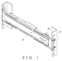
- FIG.1 shows an embodiment of a bracket assembly 10 adapted to a slide assembly 12 and a rack 14, wherein the slide assembly 12 can be mounted to the rack 14 by means of the bracket assembly 10.
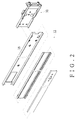
- the bracket assembly 10 can be disposed adjacent to an end of a first rail 16 (e.g., the outer rail) of the slide assembly 12.
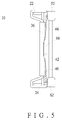
- the bracket assembly 10 comprises a bracket 18, an elastic member 20, a first arm 22, a second arm 24, and at least one inserting member 40.
- the first arm 22 is provided with a first hook portion 54
- the second arm 24 is provided with a second hook portion 64.
- the bracket 18 includes a first wall 28, a second wall 30 disposed opposite to the first wall 28, and a longitudinal body 32 connected between the first wall 28 and the second wall 30, wherein the longitudinal body 32 includes at least one assembling portion 33.
- the bracket 18 includes a first connecting base 34, a second connecting base 36 corresponding in position to the first connecting base 34, and an end plate 38 disposed on the longitudinal body 32.
- the end plate 38 is perpendicularly disposed adjacent to an end portion of the longitudinal body 32 of the bracket 18.
- the first connecting base 34 and the second connecting base 36 are disposed on the longitudinal body 32 of the bracket 18, wherein the first connecting base 34 is disposed adjacent to the first wall 28, and the second connecting base 36 is disposed adjacent to the second wall 30.
- the assembling portion 33 is preferably located between the first connecting base 34 and the second connecting base 36.
- the elastic member 20 is configured to urge at least one of the first hook portion 54 of the first arm 22 and the second hook portion 64 of the second arm 24 towards the bracket 18.
- the elastic member 20 includes a base plate 42, a first elastic portion 44, and a second elastic portion 46.
- the base plate 42 is correspondingly fit with the assembling portion 33 of the longitudinal body 32 of the bracket 18 so that the elastic member 20 can be disposed on the longitudinal body 32 of the bracket 18 and located between the first connecting base 34 and the second connecting base 36.
- the first elastic portion 44 and the second elastic portion 46 are uplifted from two opposite ends of the base plate 42, respectively.
- a predetermined included angle is formed between the first elastic portion 44 and the longitudinal body 32 of the bracket 18 for allowing the first elastic portion 44 to be pressed down elastically and thereby generate a first elastic force; also, a predetermined included angle is formed between the second elastic portion 46 and the longitudinal body 32 of the bracket 18 for allowing the second elastic portion 46 to be pressed down elastically and thereby generate a second elastic force.
- the first arm 22 is movably connected to the bracket 18.
- the first arm 22 is pivotally connected to the first connecting base 34 of the bracket 18 via a connecting element 47 and is rotatable in response to the first elastic force of the first elastic portion 44 of the elastic member 20.
- the first arm 22 includes a first portion 48 and a second portion 50 opposite to the first portion 48.
- the first portion 48 of the first arm 22 includes a first contact portion 52 correspondingly abutting against the first elastic portion 44 of the elastic member 20, wherein the first contact portion 52 can be bent to form an L-shape, but is not limited thereto.
- the second portion 50 of the first arm 22 corresponds in position to the end plate 38 of the bracket 18 and includes a first connecting portion 56, wherein the first hook portion 54 is also disposed on the second portion 50 of the first arm 22 and located close to the first connecting portion 56.
- the first hook portion 54 of the first arm 22 includes a hook surface 57 and extends in a horizontal direction, while the first connecting portion 56 extends in a vertical direction. It is noted that the second portion 50 of the first arm 22 can be moved toward and away from the end plate 38 of the bracket 18 in response to rotation of the first arm 22.
- the second arm 24 is movably connected to the bracket 18.
- the second arm 24 is pivotally connected to the second connecting base 36 of the bracket 18 via the connecting element 47 and is rotatable in response to the second elastic force of the second elastic portion 46 of the elastic member 20.
- the second arm 24 includes a first portion 58 and a second portion 60 opposite to the first portion 58.
- the first portion 58 of the second arm 24 includes a second contact portion 62 correspondingly abutting against the second elastic portion 46 of the elastic member 20, wherein the second contact portion 62 is bent to form an L-shape, but is not limited thereto.
- the second portion 60 of the second arm 24 corresponds in position to the end plate 38 of the bracket 18 and includes a second connecting portion 66, wherein the second hook portion 64 is also disposed on the second portion 60 of the second arm 24 and located close to the second connecting portion 66.
- the second hook portion 64 of the second arm 24 includes a hook surface 67 and extends in a horizontal direction, while the second connecting portion 66 extends in a vertical direction. It is noted that the second portion 60 of the second arm 24 can be moved toward and away from the end plate 38 of the bracket 18 in response to rotation of the second arm 24.
- the inserting member 40 is disposed on the end plate 38 of the bracket 18, wherein the inserting member 40 can be a circular stud, a square stud, or stud formed in other shapes. In other words, the inserting member 40 is not restricted to be formed as the circular stud illustrated in this embodiment.
- the bracket assembly 10 further comprises an operation member 26.
- the operation member 26 is assembled to or integrally formed with the first connecting portion 56 of the first arm 22 and the second connecting portion 66 of the second arm 24 and thus extends between the first connecting portion 56 of the first arm 22 and the second connecting portion 66 of the second arm 24.
- the operation member 26 can be formed into a rod-like shank with a slightly curved operating surface 68, whereby user can simply operate the operation member 26 by fingers to rotate the first arm 22 and the second arm 24, for example, from a first position (as shown in FIG.3 ) to a second position (as shown in FIG.6 ).
- the operation member 26 when the operation member 26 is not operated any more (i.e., when the force F is removed from the operating surface 68 of the operation member 26 ), the accumulated first elastic force and second elastic force are released to allow the first elastic portion 44 and the second elastic portion 46 to push against the first contact portion 52 of the first arm 22 and the second contact portion 62 of the second arm 24, respectively. Therefore, the first arm 22 and the second arm 24 are rotated back and drive the second portion 50 of the first arm 22 and the second portion 60 of the second arm 24 to move toward the end plate 38 of the bracket 18. Namely, the first arm 22 and the second arm 24 are rotated back from the second position (as shown in FIGS.6 and 7 ) to the first position (as shown in FIGS. 3 and 5 ). Simultaneously, the first elastic portion 44 and the second elastic portion 46 of the elastic member 20 return to their respect original states, i.e., uplifted from two opposite ends of the base plate 42 respectively.
- FIGS. 8 and 9 are schematic views showing how the bracket assembly 10 is assembled on the rack 14.
- the bracket assembly 10 is adapted to the rack 14 which includes at least one hole 15, wherein the hole 15 can be formed in a circle, square, or other shapes. That is to say that the hole 15 is not restricted to be formed in a circle as shown in this embodiment.
- the user To assemble the bracket 18 on the rack 14, the user initially operates the operation member 26 (as shown in FIG. 6 ) to move the second portion 50 of the first arm 22 and the second portion 60 of the second arm 24 away from the end plate 38 of the bracket 18, and simultaneously, the user moves the bracket assembly 10 toward the rack 14 in a direction D for allowing the inserting member 40 to be aligned with and received in the hole 15 of the rack 14. Consequently, the second portion 50 of the first arm 22 and the second portion 60 of the second arm 24 are spaced apart from the rack 14 by a distance during the insertion of the inserting member 40 into the hole 15 of the rack 14.
- the user stops operating the operation member 26 i.e., releases the operation member 26
- the first elastic portion 44 and the second elastic portion 46 return to their respect original states (as shown in FIG.3 ) due to their elasticity, and thus the first contact portion 52 and the second contact portion 62 are pushed against by the first elastic portion 44 and the second elastic portion 46, respectively, and thereby drive the first hook portion 54 of the second portion 50 of the first arm 22 and the second hook portion 64 of the second portion 60 of the second arm 24 to clasp the rack 14 by means of the hook surface 57 of the first hook portion 54 and the hook surface 67 of the second hook portion 64. Therefore, the bracket 18 is firmly assembled on the rack 14.
Description
- The present invention relates to a bracket assembly for a slide which can be manually operated.
- In general, a rack device is assembled on a rack by means of a pair of slide assemblies. That is to say, the rack usually comprises a first pair of supports and a second pair of supports. Wherein, the first pair of supports corresponds in position to the second pair of supports. One side of the rack device is assembled on the first pair of supports by a slide assembly; the other side of the rack device is assembled on the second pair of supports by another slide assembly. Moreover, the supports of the rack each generally include at least one mounting hole; two opposite ends of each slide assembly respectively include a bracket. The bracket has an inserting member which can be inserted into the mounting holes of the supports, whereby the two opposite ends of each slide assembly can be respectively assembled on the supports of the rack for positioning the slide assembly on the rack.
-
U.S. Patent No. 7,357,362 discloses a bracket positioning structure for a slide, in which, as shown inFIGS.2 ,3 , and5 , the bracket positioning structure for a slide is assembled on holes 71 of a support 7 via a pair of studs 2 formed on an end plate 11. Wherein, as shown inFIG.3 , the studs 2 on the end plate 11 of the bracket 1 are respectively inserted into the holes 71 of the support 7 while the bracket positioning structure is assembled on the support 7. Moreover, a tooth 43 of anarm 42 of the bracket 1 is allowed to slide along an edge of the support 7 by means of a bevel edge 431 for shifting thearm 42. While the bracket 1 is moved to a position, as shown inFIG.5 , the tooth 43 of thearm 42 of the bracket 1 will hooks the support 7 and is secured thereat, whereby the bracket 1 can be firmly positioned on the support 7. However, the bracket positioning structure does not have an operation member by which a user can control the movements of thearm 42 of the bracket 1. As a consequence, the convenience in assembling the bracket 1 on the support 7 and disassembling the bracket 1 from the support 7 is still wanted.US2013/0112638 A1 discloses the preamble of claim 1. - The present invention relates to a manually-operable bracket assembly for a slide.
- In one aspect of the present invention, a bracket assembly comprises a bracket, at least one inserting member, a first arm, and an elastic member. The bracket includes a longitudinal body and an end plate disposed on the longitudinal body. The inserting member is disposed on the end plate of the bracket. The first arm is movably connected to the bracket and has an end portion corresponding in position to the end plate of the bracket, wherein the end portion of the first arm is provided with a first hook portion. The elastic member is configured to urge the first hook portion of the first arm towards the bracket, wherein the bracket further includes a first connecting base and a second connecting base which are disposed on the longitudinal body of the bracket; the first arm is pivotally connected to the first connecting base; the bracket assembly further comprises a second arm pivotally connected to the second connecting base, characterised in that the elastic member is disposed on the bracket and located between the first connecting base and the second connecting base; the second arm has an end portion corresponding in position to the end plate of the bracket, wherein the end portion of the second arm is provided with a second hook portion; the elastic member is also configured to urge the second hook portion of the second arm towards the bracket.
- Preferably, the elastic member further includes a base plate, a first elastic portion, and a second elastic portion, wherein at least one of the first elastic portion and the second elastic portion is uplifted from one end of the base plate.
- Preferably, the bracket assembly further comprises an operation member connected between the first arm and the second arm.
- Preferably, the bracket assembly is adapted to a rack which includes at least one hole, and the bracket assembly further comprises a second arm and an operation member. The elastic member is disposed on the bracket and includes a first elastic portion and a second elastic portion. The first arm includes a first portion and a second portion opposite to the first portion, wherein the first portion of the first arm includes a first contact portion abutting against the first elastic portion of the elastic member, and wherein the second portion of the first arm is the end portion corresponding in position to the end plate of the bracket and being provided with the first hook portion. The second arm is movably connected to the bracket and includes a first portion and a second portion opposite to the first portion, wherein the first portion of the second arm includes a second contact portion abutting against the second elastic portion of the elastic member, and wherein the second portion of the second arm corresponds in position to the end plate of the bracket and includes a second hook portion. The operation member is connected between the first arm and the second arm. When the bracket assembly is mounted on the rack, the at least one inserting member is inserted into the at least one hole of the rack, and meanwhile, the first hook portion of the second portion of the first arm and the second hook portion of the second portion of the second arm clasp the rack due to elastic force against the first contact portion and the second contact portion provided by the first elastic portion and the second elastic portion.
- Preferably, the elastic member further includes a base plate, wherein the first elastic portion and the second elastic portion are uplifted from two opposite ends of the base plate, respectively.
- Preferably, the bracket assembly further comprises a second arm and an operation member. The bracket further includes a first connecting base and a second connecting base corresponding in position to the first connecting base, wherein the first connecting base and the second connecting base are disposed on the longitudinal body. The elastic member is disposed on the bracket and located between the first connecting base and the second connecting base of the bracket and includes a first elastic portion and a second elastic portion. The first arm is pivotally connected to the first connecting base of the bracket and includes a first portion and a second portion opposite to the first portion, wherein the first portion of the first arm includes a first contact portion abutting against the first elastic portion of the elastic member, wherein the second portion of the first arm is the end portion corresponding in position to the end plate of the bracket and being provided with the first hook portion, and wherein the second portion of the first arm is further provided with a first connecting portion disposed close to the first hook portion. The second arm is pivotally connected to the second connecting base of the bracket and includes a first portion and a second portion opposite to the first portion, wherein the first portion of the second arm includes a second contact portion abutting against the second elastic portion of the elastic member, and wherein the second portion of the second arm corresponds in position to the end plate of the bracket and includes a second hook portion and a second connecting portion disposed close to the second hook portion. The operation member is connected between the first connecting portion of the first arm and the second connecting portion of the second arm.
- Preferably, the elastic member further includes a base plate, wherein the first elastic portion and the second elastic portion are uplifted from two opposite ends of the base plate, respectively.
- One characteristic of the embodiment of the present invention is that the bracket assembly is adapted to a slide assembly and can be assembled on a rack; moreover, when a user operates the operation member and does not release it until an inserting member of the bracket assembly is inserted into a hole of the rack, a hook portion of a arm can be driven to clasp the rack due to the elastic force provided by an elastic member, thus assembling the bracket assembly on the rack.
-
-
FIG.1 is a perspective view showing a bracket assembly which is disposed on a slide assembly and assembled on a rack; -
FIG.2 is an exploded view ofFIG.1 showing the bracket assembly which is disposed adjacent to one end of the slide assembly; -
FIG.3 is a perspective view showing a bracket assembly in accordance with an embodiment of the present invention; -
FIG.4 is an exploded view showing a bracket assembly in accordance with the embodiment of the present invention; -
FIG.5 is schematic view showing a first contact portion and a second contact portion abut against a first elastic portion and a second elastic portion, respectively, while an operation member has not yet been operated; -
FIG.6 is a schematic view showing a second portion of a first arm and a second portion of a second arm are moved away from an end plate of the bracket while the operation member is operated; -
FIG.7 is a schematic view showing the first contact portion and the second contact portion press against the first elastic portion and the second elastic portion, respectively, while the operation member is operated; -
FIG. 8 is a schematic view showing operations of assembling the bracket assembly on the rack; -
FIG.9 is another schematic view showing operations of assembling the bracket assembly on the rack; and -
FIG.10 is a perspective showing the bracket assembly positioned on the rack, wherein the first hook portion of the first arm and the second hook portion of the second arm clasp the rack. -
FIG.1 shows an embodiment of abracket assembly 10 adapted to aslide assembly 12 and arack 14, wherein theslide assembly 12 can be mounted to therack 14 by means of thebracket assembly 10. As shown inFIG.2 , thebracket assembly 10 can be disposed adjacent to an end of a first rail 16 (e.g., the outer rail) of theslide assembly 12. - Referring to
FIGS.3 to 5 , thebracket assembly 10 comprises abracket 18, anelastic member 20, afirst arm 22, asecond arm 24, and at least oneinserting member 40. Thefirst arm 22 is provided with afirst hook portion 54, and thesecond arm 24 is provided with asecond hook portion 64. - The
bracket 18 includes afirst wall 28, asecond wall 30 disposed opposite to thefirst wall 28, and alongitudinal body 32 connected between thefirst wall 28 and thesecond wall 30, wherein thelongitudinal body 32 includes at least one assemblingportion 33. - In more detail, the
bracket 18 includes a first connectingbase 34, a second connectingbase 36 corresponding in position to the first connectingbase 34, and anend plate 38 disposed on thelongitudinal body 32. Preferably, theend plate 38 is perpendicularly disposed adjacent to an end portion of thelongitudinal body 32 of thebracket 18. The first connectingbase 34 and the second connectingbase 36 are disposed on thelongitudinal body 32 of thebracket 18, wherein the first connectingbase 34 is disposed adjacent to thefirst wall 28, and the second connectingbase 36 is disposed adjacent to thesecond wall 30. The assemblingportion 33 is preferably located between the first connectingbase 34 and the second connectingbase 36. - The
elastic member 20 is configured to urge at least one of thefirst hook portion 54 of thefirst arm 22 and thesecond hook portion 64 of thesecond arm 24 towards thebracket 18. In one preferred embodiment, theelastic member 20 includes abase plate 42, a firstelastic portion 44, and a secondelastic portion 46. Thebase plate 42 is correspondingly fit with the assemblingportion 33 of thelongitudinal body 32 of thebracket 18 so that theelastic member 20 can be disposed on thelongitudinal body 32 of thebracket 18 and located between the first connectingbase 34 and the second connectingbase 36. The firstelastic portion 44 and the secondelastic portion 46 are uplifted from two opposite ends of thebase plate 42, respectively. Accordingly, a predetermined included angle is formed between the firstelastic portion 44 and thelongitudinal body 32 of thebracket 18 for allowing the firstelastic portion 44 to be pressed down elastically and thereby generate a first elastic force; also, a predetermined included angle is formed between the secondelastic portion 46 and thelongitudinal body 32 of thebracket 18 for allowing the secondelastic portion 46 to be pressed down elastically and thereby generate a second elastic force. - The
first arm 22 is movably connected to thebracket 18. Preferably, thefirst arm 22 is pivotally connected to the first connectingbase 34 of thebracket 18 via a connectingelement 47 and is rotatable in response to the first elastic force of the firstelastic portion 44 of theelastic member 20. Further, thefirst arm 22 includes afirst portion 48 and asecond portion 50 opposite to thefirst portion 48. Thefirst portion 48 of thefirst arm 22 includes afirst contact portion 52 correspondingly abutting against the firstelastic portion 44 of theelastic member 20, wherein thefirst contact portion 52 can be bent to form an L-shape, but is not limited thereto. Thesecond portion 50 of thefirst arm 22 corresponds in position to theend plate 38 of thebracket 18 and includes a first connectingportion 56, wherein thefirst hook portion 54 is also disposed on thesecond portion 50 of thefirst arm 22 and located close to the first connectingportion 56. Thefirst hook portion 54 of thefirst arm 22 includes ahook surface 57 and extends in a horizontal direction, while the first connectingportion 56 extends in a vertical direction. It is noted that thesecond portion 50 of thefirst arm 22 can be moved toward and away from theend plate 38 of thebracket 18 in response to rotation of thefirst arm 22. - The
second arm 24 is movably connected to thebracket 18. Preferably, thesecond arm 24 is pivotally connected to the second connectingbase 36 of thebracket 18 via the connectingelement 47 and is rotatable in response to the second elastic force of the secondelastic portion 46 of theelastic member 20. Thesecond arm 24 includes afirst portion 58 and asecond portion 60 opposite to thefirst portion 58. Thefirst portion 58 of thesecond arm 24 includes asecond contact portion 62 correspondingly abutting against the secondelastic portion 46 of theelastic member 20, wherein thesecond contact portion 62 is bent to form an L-shape, but is not limited thereto. Thesecond portion 60 of thesecond arm 24 corresponds in position to theend plate 38 of thebracket 18 and includes a second connectingportion 66, wherein thesecond hook portion 64 is also disposed on thesecond portion 60 of thesecond arm 24 and located close to the second connectingportion 66. Thesecond hook portion 64 of thesecond arm 24 includes a hook surface 67 and extends in a horizontal direction, while the second connectingportion 66 extends in a vertical direction. It is noted that thesecond portion 60 of thesecond arm 24 can be moved toward and away from theend plate 38 of thebracket 18 in response to rotation of thesecond arm 24. - The inserting
member 40 is disposed on theend plate 38 of thebracket 18, wherein the insertingmember 40 can be a circular stud, a square stud, or stud formed in other shapes. In other words, the insertingmember 40 is not restricted to be formed as the circular stud illustrated in this embodiment. - Preferably, the
bracket assembly 10 further comprises anoperation member 26. Theoperation member 26 is assembled to or integrally formed with the first connectingportion 56 of thefirst arm 22 and the second connectingportion 66 of thesecond arm 24 and thus extends between the first connectingportion 56 of thefirst arm 22 and the second connectingportion 66 of thesecond arm 24. Theoperation member 26 can be formed into a rod-like shank with a slightlycurved operating surface 68, whereby user can simply operate theoperation member 26 by fingers to rotate thefirst arm 22 and thesecond arm 24, for example, from a first position (as shown inFIG.3 ) to a second position (as shown inFIG.6 ). - Referring to
FIGS.6 and7 , when a user exerts a force F on the operatingsurface 68 of theoperation member 26, thefirst arm 22 and thesecond arm 24 are driven to rotate from the first position (as shown inFIGS.3 and5 ) to the second position (as shown inFIGS. 6 and7 ) and make thesecond portion 50 of thefirst arm 22 and thesecond portion 60 of thesecond arm 24 be moved away from theend plate 38 of thebracket 18 due to the fact that thefirst arm 22 and thesecond arm 24 are pivotally connected to the first connectingbase 34 and the second connectingbase 36, respectively; meanwhile, the firstelastic portion 44 is pressed against by thefirst contact portion 52 of thefirst arm 22 to accumulate the first elastic force, and the secondelastic portion 46 of theelastic member 20 is pressed against by thesecond contact portion 62 of thesecond arm 24 to accumulate the second elastic force. - Further, when the
operation member 26 is not operated any more (i.e., when the force F is removed from the operatingsurface 68 of the operation member 26), the accumulated first elastic force and second elastic force are released to allow the firstelastic portion 44 and the secondelastic portion 46 to push against thefirst contact portion 52 of thefirst arm 22 and thesecond contact portion 62 of thesecond arm 24, respectively. Therefore, thefirst arm 22 and thesecond arm 24 are rotated back and drive thesecond portion 50 of thefirst arm 22 and thesecond portion 60 of thesecond arm 24 to move toward theend plate 38 of thebracket 18. Namely, thefirst arm 22 and thesecond arm 24 are rotated back from the second position (as shown inFIGS.6 and7 ) to the first position (as shown inFIGS. 3 and5 ). Simultaneously, the firstelastic portion 44 and the secondelastic portion 46 of theelastic member 20 return to their respect original states, i.e., uplifted from two opposite ends of thebase plate 42 respectively. -
FIGS. 8 and 9 are schematic views showing how thebracket assembly 10 is assembled on therack 14. - Specifically, the
bracket assembly 10 is adapted to therack 14 which includes at least onehole 15, wherein thehole 15 can be formed in a circle, square, or other shapes. That is to say that thehole 15 is not restricted to be formed in a circle as shown in this embodiment. - To assemble the
bracket 18 on therack 14, the user initially operates the operation member 26 (as shown inFIG. 6 ) to move thesecond portion 50 of thefirst arm 22 and thesecond portion 60 of thesecond arm 24 away from theend plate 38 of thebracket 18, and simultaneously, the user moves thebracket assembly 10 toward therack 14 in a direction D for allowing the insertingmember 40 to be aligned with and received in thehole 15 of therack 14. Consequently, thesecond portion 50 of thefirst arm 22 and thesecond portion 60 of thesecond arm 24 are spaced apart from therack 14 by a distance during the insertion of the insertingmember 40 into thehole 15 of therack 14. - Subsequently, referring to
FIG.10 , the user stops operating the operation member 26 (i.e., releases the operation member 26) after the insertingmember 40 is inserted into thehole 15 of therack 14. As a result, the firstelastic portion 44 and the secondelastic portion 46 return to their respect original states (as shown inFIG.3 ) due to their elasticity, and thus thefirst contact portion 52 and thesecond contact portion 62 are pushed against by the firstelastic portion 44 and the secondelastic portion 46, respectively, and thereby drive thefirst hook portion 54 of thesecond portion 50 of thefirst arm 22 and thesecond hook portion 64 of thesecond portion 60 of thesecond arm 24 to clasp therack 14 by means of thehook surface 57 of thefirst hook portion 54 and the hook surface 67 of thesecond hook portion 64. Therefore, thebracket 18 is firmly assembled on therack 14.
Claims (7)
- A bracket assembly (10) for a slide, comprising:a bracket (18) including a longitudinal body (32) and an end plate (38) disposed on the longitudinal body (32);at least one inserting member (40) disposed on the end plate (38) of the bracket (18);a first arm (22) movably connected to the bracket (18), the first arm (22) having an end portion corresponding in position to the end plate (38) of the bracket (18), the end portion of the first arm (22) being provided with a first hook portion (54); andan elastic member (20) configured to urge the first hook portion (54) of the first arm (22) towards the bracket (18), wherein the bracket (18) further includes a first connecting base (34) and a second connecting base (36) which are disposed on the longitudinal body (32) of the bracket (18), wherein the first arm (22) is pivotally connected to the first connecting base (34), and wherein the bracket assembly (10) further comprises a second arm (24) pivotally connected to the second connecting base (36), characterised in thatthe elastic member (20) is disposed on the bracket (18) and located between the first connecting base (34) and the second connecting base (36), wherein the second arm (24) has an end portion corresponding in position to the end plate (38) of the bracket (18), wherein the end portion of the second arm (24) is provided with a second hook portion (64), and wherein the elastic member (20) is also configured to urge the second hook portion (64) of the second arm (24) towards the bracket (18).
- The bracket assembly (10) as claimed in claim 1, wherein the elastic member (20) further includes a base plate (42), a first elastic portion (44), and a second elastic portion (46), and wherein at least one of the first elastic portion (44) and the second elastic portion (46) is uplifted from one end of the base plate (42).
- The bracket assembly (10) as claimed in claim 1, further comprising an operation member (26) connected between the first arm (22) and the second arm (24).
- The bracket assembly (10) as claimed in claim 1, wherein the bracket assembly (10) is adapted to a rack (14) which includes at least one hole (15), and the bracket assembly (10) further comprises an operation member (26) connected between the first arm (22) and the second arm (24);
wherein the elastic member (20) includes a first elastic portion (44) and a second elastic portion (46);
wherein the first arm (22) includes a first portion (48) and a second portion (50) opposite to the first portion (48), wherein the first portion (48) of the first arm (22) includes a first contact portion (52) abutting against the first elastic portion (44) of the elastic member (20), and wherein the second portion (50) of the first arm (22) is the end portion corresponding in position to the end plate (38) of the bracket (18) and being provided with the first hook portion (54);
wherein the second arm (24) includes a first portion (58) and a second portion (60) opposite to the first portion (58), wherein the first portion (58) of the second arm (24) includes a second contact portion (62) abutting against the second elastic portion (46) of the elastic member (20), and wherein the second portion (60) of the second arm (24) is the end portion corresponding in position to the end plate (38) of the bracket (18) and being provided with the second hook portion (64); and
wherein, when the bracket assembly (10) is mounted on the rack (14), the at least one inserting member (40) is inserted into the at least one hole (15) of the rack (14), and meanwhile, the first hook portion (54) of the second portion (50) of the first arm (22) and the second hook portion (64) of the second portion (60) of the second arm (24) clasp the rack (14) due to elastic force against the first contact portion (52) and the second contact portion (62) provided by the first elastic portion (44) and the second elastic portion (46). - The bracket assembly (10) as claimed in claim 4 , wherein the elastic member (20) further includes a base plate (42), and the first elastic portion (44) and the second elastic portion (46) are uplifted from two opposite ends of the base plate (42), respectively.
- The bracket assembly (10) as claimed in claim 1, further comprising an operation member (26);
wherein the elastic member (20) includes a first elastic portion (44) and a second elastic portion (46);
wherein the first arm (22) includes a first portion (48) and a second portion (50) opposite to the first portion (48), wherein the first portion (48) of the first arm (22) includes a first contact portion (52) abutting against the first elastic portion (44) of the elastic member (20), wherein the second portion (50) of the first arm (22) is the end portion corresponding in position to the end plate (38) of the bracket (18) and being provided with the first hook portion (54), and wherein the second portion (50) of the first arm (22) is further provided with a first connecting portion (56) disposed close to the first hook portion (54);
wherein the second arm (24) includes a first portion (58) and a second portion (60) opposite to the first portion (58), wherein the first portion (58) of the second arm (24) includes a second contact portion (62) abutting against the second elastic portion (46) of the elastic member (20), wherein the second portion (60) of the second arm (24) is the end portion corresponding in position to the end plate (38) of the bracket (18) and being provided with the second hook portion (64), and wherein the second portion (60) of the second arm (24) is further provided with a second connecting portion (66) disposed close to the second hook portion (64); and
wherein the operation member (26) is connected between the first connecting portion (56) of the first arm (22) and the second connecting portion (66) of the second arm (24). - The bracket assembly (10) as claimed in claim 6, wherein the elastic member (20) further includes a base plate (42), and wherein the first elastic portion (44) and the second elastic portion (46) are uplifted from two opposite ends of the base plate (42), respectively.
Priority Applications (1)
| Application Number | Priority Date | Filing Date | Title |
|---|---|---|---|
| EP14170151.6A EP2949238B1 (en) | 2014-05-28 | 2014-05-28 | Bracket assembly for slide |
Applications Claiming Priority (1)
| Application Number | Priority Date | Filing Date | Title |
|---|---|---|---|
| EP14170151.6A EP2949238B1 (en) | 2014-05-28 | 2014-05-28 | Bracket assembly for slide |
Publications (2)
| Publication Number | Publication Date |
|---|---|
| EP2949238A1 EP2949238A1 (en) | 2015-12-02 |
| EP2949238B1 true EP2949238B1 (en) | 2016-07-06 |
Family
ID=50897370
Family Applications (1)
| Application Number | Title | Priority Date | Filing Date |
|---|---|---|---|
| EP14170151.6A Active EP2949238B1 (en) | 2014-05-28 | 2014-05-28 | Bracket assembly for slide |
Country Status (1)
| Country | Link |
|---|---|
| EP (1) | EP2949238B1 (en) |
Families Citing this family (1)
| Publication number | Priority date | Publication date | Assignee | Title |
|---|---|---|---|---|
| TWI640277B (en) * | 2017-09-15 | 2018-11-11 | 川湖科技股份有限公司 | Slide rail assembly and bracket device thereof |
Family Cites Families (4)
| Publication number | Priority date | Publication date | Assignee | Title |
|---|---|---|---|---|
| TWM255624U (en) | 2003-12-30 | 2005-01-11 | King Slide Works Co Ltd | Positioning device for sliding track bracket |
| TWI354528B (en) * | 2008-09-01 | 2011-12-11 | King Slide Works Co Ltd | Bracket assembly |
| TW201249310A (en) * | 2011-05-18 | 2012-12-01 | Hon Hai Prec Ind Co Ltd | Fixing apparatus for slide rail |
| US8727138B2 (en) * | 2011-11-04 | 2014-05-20 | International Business Machines Corporation | Toolless rail enabling simplified installation and removal |
-
2014
- 2014-05-28 EP EP14170151.6A patent/EP2949238B1/en active Active
Also Published As
| Publication number | Publication date |
|---|---|
| EP2949238A1 (en) | 2015-12-02 |
Similar Documents
| Publication | Publication Date | Title |
|---|---|---|
| US9237808B2 (en) | Bracket assembly for slide | |
| US10455938B2 (en) | Slide rail assembly | |
| US9375087B1 (en) | Bracket and mounting device thereof | |
| US10935179B2 (en) | Wire pressing and holding device for an extension arm support mechanism | |
| US9480183B2 (en) | Slide rail assembly | |
| US9066591B2 (en) | Fixing device for a slide assembly | |
| CN204729406U (en) | Clamping fastener device | |
| TWI590783B (en) | Bracket positioning device of slide | |
| US8695682B2 (en) | Pull bar device for a sunshade assembly | |
| US20170232493A1 (en) | Bending tool and gripping device for manipulating the bending tool | |
| EP2949238B1 (en) | Bracket assembly for slide | |
| JP3192322U (en) | Positioning device | |
| JP6595394B2 (en) | Nut holder, nut member, fastener, mounting tool and manufacturing method | |
| JP3191618U (en) | Slide rail system and connecting device used for the slide rail system | |
| EP2612572A1 (en) | Installation device for slide assembly | |
| EP3032930B1 (en) | Bracket and mounting device thereof | |
| EP2813161A1 (en) | Fixing device for a slide assembly | |
| EP2979582A1 (en) | Slide rail assembly | |
| JP4713527B2 (en) | Support device | |
| EP2412578A1 (en) | Device for detachably attaching a holder for an electronic device | |
| US20140305271A1 (en) | Paper punch with adjustable punch seats | |
| EP2813160B1 (en) | Fixing device for a slide assembly | |
| JP2008188361A (en) | Stopper device for transfer utensil | |
| JP4427369B2 (en) | Panel furniture with armbands | |
| EP2937017A1 (en) | Mounting device for drawer system |
Legal Events
| Date | Code | Title | Description |
|---|---|---|---|
| 17P | Request for examination filed |
Effective date: 20150521 |
|
| AK | Designated contracting states |
Kind code of ref document: A1 Designated state(s): AL AT BE BG CH CY CZ DE DK EE ES FI FR GB GR HR HU IE IS IT LI LT LU LV MC MK MT NL NO PL PT RO RS SE SI SK SM TR |
|
| AX | Request for extension of the european patent |
Extension state: BA ME |
|
| PUAI | Public reference made under article 153(3) epc to a published international application that has entered the european phase |
Free format text: ORIGINAL CODE: 0009012 |
|
| GRAP | Despatch of communication of intention to grant a patent |
Free format text: ORIGINAL CODE: EPIDOSNIGR1 |
|
| INTG | Intention to grant announced |
Effective date: 20160115 |
|
| GRAS | Grant fee paid |
Free format text: ORIGINAL CODE: EPIDOSNIGR3 |
|
| GRAA | (expected) grant |
Free format text: ORIGINAL CODE: 0009210 |
|
| AK | Designated contracting states |
Kind code of ref document: B1 Designated state(s): AL AT BE BG CH CY CZ DE DK EE ES FI FR GB GR HR HU IE IS IT LI LT LU LV MC MK MT NL NO PL PT RO RS SE SI SK SM TR |
|
| REG | Reference to a national code |
Ref country code: GB Ref legal event code: FG4D |
|
| REG | Reference to a national code |
Ref country code: AT Ref legal event code: REF Ref document number: 810073 Country of ref document: AT Kind code of ref document: T Effective date: 20160715 Ref country code: CH Ref legal event code: EP |
|
| REG | Reference to a national code |
Ref country code: IE Ref legal event code: FG4D |
|
| REG | Reference to a national code |
Ref country code: DE Ref legal event code: R096 Ref document number: 602014002554 Country of ref document: DE |
|
| REG | Reference to a national code |
Ref country code: NL Ref legal event code: FP |
|
| REG | Reference to a national code |
Ref country code: LT Ref legal event code: MG4D |
|
| REG | Reference to a national code |
Ref country code: DE Ref legal event code: R079 Ref document number: 602014002554 Country of ref document: DE Free format text: PREVIOUS MAIN CLASS: A47B0088040000 Ipc: A47B0088400000 |
|
| REG | Reference to a national code |
Ref country code: AT Ref legal event code: MK05 Ref document number: 810073 Country of ref document: AT Kind code of ref document: T Effective date: 20160706 |
|
| PG25 | Lapsed in a contracting state [announced via postgrant information from national office to epo] |
Ref country code: IS Free format text: LAPSE BECAUSE OF FAILURE TO SUBMIT A TRANSLATION OF THE DESCRIPTION OR TO PAY THE FEE WITHIN THE PRESCRIBED TIME-LIMIT Effective date: 20161106 Ref country code: IT Free format text: LAPSE BECAUSE OF FAILURE TO SUBMIT A TRANSLATION OF THE DESCRIPTION OR TO PAY THE FEE WITHIN THE PRESCRIBED TIME-LIMIT Effective date: 20160706 Ref country code: NO Free format text: LAPSE BECAUSE OF FAILURE TO SUBMIT A TRANSLATION OF THE DESCRIPTION OR TO PAY THE FEE WITHIN THE PRESCRIBED TIME-LIMIT Effective date: 20161006 Ref country code: LT Free format text: LAPSE BECAUSE OF FAILURE TO SUBMIT A TRANSLATION OF THE DESCRIPTION OR TO PAY THE FEE WITHIN THE PRESCRIBED TIME-LIMIT Effective date: 20160706 Ref country code: HR Free format text: LAPSE BECAUSE OF FAILURE TO SUBMIT A TRANSLATION OF THE DESCRIPTION OR TO PAY THE FEE WITHIN THE PRESCRIBED TIME-LIMIT Effective date: 20160706 Ref country code: RS Free format text: LAPSE BECAUSE OF FAILURE TO SUBMIT A TRANSLATION OF THE DESCRIPTION OR TO PAY THE FEE WITHIN THE PRESCRIBED TIME-LIMIT Effective date: 20160706 Ref country code: FI Free format text: LAPSE BECAUSE OF FAILURE TO SUBMIT A TRANSLATION OF THE DESCRIPTION OR TO PAY THE FEE WITHIN THE PRESCRIBED TIME-LIMIT Effective date: 20160706 |
|
| PG25 | Lapsed in a contracting state [announced via postgrant information from national office to epo] |
Ref country code: PL Free format text: LAPSE BECAUSE OF FAILURE TO SUBMIT A TRANSLATION OF THE DESCRIPTION OR TO PAY THE FEE WITHIN THE PRESCRIBED TIME-LIMIT Effective date: 20160706 Ref country code: BE Free format text: LAPSE BECAUSE OF FAILURE TO SUBMIT A TRANSLATION OF THE DESCRIPTION OR TO PAY THE FEE WITHIN THE PRESCRIBED TIME-LIMIT Effective date: 20160706 Ref country code: LV Free format text: LAPSE BECAUSE OF FAILURE TO SUBMIT A TRANSLATION OF THE DESCRIPTION OR TO PAY THE FEE WITHIN THE PRESCRIBED TIME-LIMIT Effective date: 20160706 Ref country code: PT Free format text: LAPSE BECAUSE OF FAILURE TO SUBMIT A TRANSLATION OF THE DESCRIPTION OR TO PAY THE FEE WITHIN THE PRESCRIBED TIME-LIMIT Effective date: 20161107 Ref country code: AT Free format text: LAPSE BECAUSE OF FAILURE TO SUBMIT A TRANSLATION OF THE DESCRIPTION OR TO PAY THE FEE WITHIN THE PRESCRIBED TIME-LIMIT Effective date: 20160706 Ref country code: SE Free format text: LAPSE BECAUSE OF FAILURE TO SUBMIT A TRANSLATION OF THE DESCRIPTION OR TO PAY THE FEE WITHIN THE PRESCRIBED TIME-LIMIT Effective date: 20160706 Ref country code: ES Free format text: LAPSE BECAUSE OF FAILURE TO SUBMIT A TRANSLATION OF THE DESCRIPTION OR TO PAY THE FEE WITHIN THE PRESCRIBED TIME-LIMIT Effective date: 20160706 |
|
| REG | Reference to a national code |
Ref country code: DE Ref legal event code: R097 Ref document number: 602014002554 Country of ref document: DE |
|
| PG25 | Lapsed in a contracting state [announced via postgrant information from national office to epo] |
Ref country code: EE Free format text: LAPSE BECAUSE OF FAILURE TO SUBMIT A TRANSLATION OF THE DESCRIPTION OR TO PAY THE FEE WITHIN THE PRESCRIBED TIME-LIMIT Effective date: 20160706 Ref country code: RO Free format text: LAPSE BECAUSE OF FAILURE TO SUBMIT A TRANSLATION OF THE DESCRIPTION OR TO PAY THE FEE WITHIN THE PRESCRIBED TIME-LIMIT Effective date: 20160706 |
|
| PLBE | No opposition filed within time limit |
Free format text: ORIGINAL CODE: 0009261 |
|
| STAA | Information on the status of an ep patent application or granted ep patent |
Free format text: STATUS: NO OPPOSITION FILED WITHIN TIME LIMIT |
|
| PG25 | Lapsed in a contracting state [announced via postgrant information from national office to epo] |
Ref country code: SK Free format text: LAPSE BECAUSE OF FAILURE TO SUBMIT A TRANSLATION OF THE DESCRIPTION OR TO PAY THE FEE WITHIN THE PRESCRIBED TIME-LIMIT Effective date: 20160706 Ref country code: BG Free format text: LAPSE BECAUSE OF FAILURE TO SUBMIT A TRANSLATION OF THE DESCRIPTION OR TO PAY THE FEE WITHIN THE PRESCRIBED TIME-LIMIT Effective date: 20161006 Ref country code: DK Free format text: LAPSE BECAUSE OF FAILURE TO SUBMIT A TRANSLATION OF THE DESCRIPTION OR TO PAY THE FEE WITHIN THE PRESCRIBED TIME-LIMIT Effective date: 20160706 Ref country code: CZ Free format text: LAPSE BECAUSE OF FAILURE TO SUBMIT A TRANSLATION OF THE DESCRIPTION OR TO PAY THE FEE WITHIN THE PRESCRIBED TIME-LIMIT Effective date: 20160706 Ref country code: SM Free format text: LAPSE BECAUSE OF FAILURE TO SUBMIT A TRANSLATION OF THE DESCRIPTION OR TO PAY THE FEE WITHIN THE PRESCRIBED TIME-LIMIT Effective date: 20160706 |
|
| 26N | No opposition filed |
Effective date: 20170407 |
|
| PG25 | Lapsed in a contracting state [announced via postgrant information from national office to epo] |
Ref country code: LU Free format text: LAPSE BECAUSE OF NON-PAYMENT OF DUE FEES Effective date: 20170531 Ref country code: SI Free format text: LAPSE BECAUSE OF FAILURE TO SUBMIT A TRANSLATION OF THE DESCRIPTION OR TO PAY THE FEE WITHIN THE PRESCRIBED TIME-LIMIT Effective date: 20160706 |
|
| REG | Reference to a national code |
Ref country code: CH Ref legal event code: PL |
|
| PG25 | Lapsed in a contracting state [announced via postgrant information from national office to epo] |
Ref country code: MC Free format text: LAPSE BECAUSE OF FAILURE TO SUBMIT A TRANSLATION OF THE DESCRIPTION OR TO PAY THE FEE WITHIN THE PRESCRIBED TIME-LIMIT Effective date: 20160706 |
|
| REG | Reference to a national code |
Ref country code: IE Ref legal event code: MM4A |
|
| PG25 | Lapsed in a contracting state [announced via postgrant information from national office to epo] |
Ref country code: LI Free format text: LAPSE BECAUSE OF NON-PAYMENT OF DUE FEES Effective date: 20170531 Ref country code: CH Free format text: LAPSE BECAUSE OF NON-PAYMENT OF DUE FEES Effective date: 20170531 |
|
| REG | Reference to a national code |
Ref country code: FR Ref legal event code: ST Effective date: 20180131 |
|
| PG25 | Lapsed in a contracting state [announced via postgrant information from national office to epo] |
Ref country code: LU Free format text: LAPSE BECAUSE OF NON-PAYMENT OF DUE FEES Effective date: 20170528 |
|
| PG25 | Lapsed in a contracting state [announced via postgrant information from national office to epo] |
Ref country code: IE Free format text: LAPSE BECAUSE OF NON-PAYMENT OF DUE FEES Effective date: 20170528 |
|
| PG25 | Lapsed in a contracting state [announced via postgrant information from national office to epo] |
Ref country code: FR Free format text: LAPSE BECAUSE OF NON-PAYMENT OF DUE FEES Effective date: 20170531 |
|
| PG25 | Lapsed in a contracting state [announced via postgrant information from national office to epo] |
Ref country code: MT Free format text: LAPSE BECAUSE OF NON-PAYMENT OF DUE FEES Effective date: 20170528 |
|
| PG25 | Lapsed in a contracting state [announced via postgrant information from national office to epo] |
Ref country code: AL Free format text: LAPSE BECAUSE OF FAILURE TO SUBMIT A TRANSLATION OF THE DESCRIPTION OR TO PAY THE FEE WITHIN THE PRESCRIBED TIME-LIMIT Effective date: 20160706 |
|
| PG25 | Lapsed in a contracting state [announced via postgrant information from national office to epo] |
Ref country code: HU Free format text: LAPSE BECAUSE OF FAILURE TO SUBMIT A TRANSLATION OF THE DESCRIPTION OR TO PAY THE FEE WITHIN THE PRESCRIBED TIME-LIMIT; INVALID AB INITIO Effective date: 20140528 |
|
| PG25 | Lapsed in a contracting state [announced via postgrant information from national office to epo] |
Ref country code: CY Free format text: LAPSE BECAUSE OF FAILURE TO SUBMIT A TRANSLATION OF THE DESCRIPTION OR TO PAY THE FEE WITHIN THE PRESCRIBED TIME-LIMIT Effective date: 20160706 |
|
| PG25 | Lapsed in a contracting state [announced via postgrant information from national office to epo] |
Ref country code: MK Free format text: LAPSE BECAUSE OF FAILURE TO SUBMIT A TRANSLATION OF THE DESCRIPTION OR TO PAY THE FEE WITHIN THE PRESCRIBED TIME-LIMIT Effective date: 20160706 |
|
| PG25 | Lapsed in a contracting state [announced via postgrant information from national office to epo] |
Ref country code: TR Free format text: LAPSE BECAUSE OF FAILURE TO SUBMIT A TRANSLATION OF THE DESCRIPTION OR TO PAY THE FEE WITHIN THE PRESCRIBED TIME-LIMIT Effective date: 20160706 |
|
| PG25 | Lapsed in a contracting state [announced via postgrant information from national office to epo] |
Ref country code: GR Free format text: LAPSE BECAUSE OF FAILURE TO SUBMIT A TRANSLATION OF THE DESCRIPTION OR TO PAY THE FEE WITHIN THE PRESCRIBED TIME-LIMIT Effective date: 20160706 |
|
| PGFP | Annual fee paid to national office [announced via postgrant information from national office to epo] |
Ref country code: NL Payment date: 20230510 Year of fee payment: 10 Ref country code: DE Payment date: 20230510 Year of fee payment: 10 |
|
| PGFP | Annual fee paid to national office [announced via postgrant information from national office to epo] |
Ref country code: GB Payment date: 20230508 Year of fee payment: 10 |