EP2948647B1 - Système volumétrique de récupération d'énergie par détente à trois étages - Google Patents
Système volumétrique de récupération d'énergie par détente à trois étages Download PDFInfo
- Publication number
- EP2948647B1 EP2948647B1 EP14704724.5A EP14704724A EP2948647B1 EP 2948647 B1 EP2948647 B1 EP 2948647B1 EP 14704724 A EP14704724 A EP 14704724A EP 2948647 B1 EP2948647 B1 EP 2948647B1
- Authority
- EP
- European Patent Office
- Prior art keywords
- working fluid
- heat
- fluid
- heat exchanger
- stream
- Prior art date
- Legal status (The legal status is an assumption and is not a legal conclusion. Google has not performed a legal analysis and makes no representation as to the accuracy of the status listed.)
- Not-in-force
Links
Images


Classifications
-
- F—MECHANICAL ENGINEERING; LIGHTING; HEATING; WEAPONS; BLASTING
- F01—MACHINES OR ENGINES IN GENERAL; ENGINE PLANTS IN GENERAL; STEAM ENGINES
- F01K—STEAM ENGINE PLANTS; STEAM ACCUMULATORS; ENGINE PLANTS NOT OTHERWISE PROVIDED FOR; ENGINES USING SPECIAL WORKING FLUIDS OR CYCLES
- F01K7/00—Steam engine plants characterised by the use of specific types of engine; Plants or engines characterised by their use of special steam systems, cycles or processes; Control means specially adapted for such systems, cycles or processes; Use of withdrawn or exhaust steam for feed-water heating
- F01K7/16—Steam engine plants characterised by the use of specific types of engine; Plants or engines characterised by their use of special steam systems, cycles or processes; Control means specially adapted for such systems, cycles or processes; Use of withdrawn or exhaust steam for feed-water heating the engines being only of turbine type
- F01K7/22—Steam engine plants characterised by the use of specific types of engine; Plants or engines characterised by their use of special steam systems, cycles or processes; Control means specially adapted for such systems, cycles or processes; Use of withdrawn or exhaust steam for feed-water heating the engines being only of turbine type the turbines having inter-stage steam heating
-
- F—MECHANICAL ENGINEERING; LIGHTING; HEATING; WEAPONS; BLASTING
- F01—MACHINES OR ENGINES IN GENERAL; ENGINE PLANTS IN GENERAL; STEAM ENGINES
- F01K—STEAM ENGINE PLANTS; STEAM ACCUMULATORS; ENGINE PLANTS NOT OTHERWISE PROVIDED FOR; ENGINES USING SPECIAL WORKING FLUIDS OR CYCLES
- F01K23/00—Plants characterised by more than one engine delivering power external to the plant, the engines being driven by different fluids
- F01K23/02—Plants characterised by more than one engine delivering power external to the plant, the engines being driven by different fluids the engine cycles being thermally coupled
- F01K23/06—Plants characterised by more than one engine delivering power external to the plant, the engines being driven by different fluids the engine cycles being thermally coupled combustion heat from one cycle heating the fluid in another cycle
- F01K23/10—Plants characterised by more than one engine delivering power external to the plant, the engines being driven by different fluids the engine cycles being thermally coupled combustion heat from one cycle heating the fluid in another cycle with exhaust fluid of one cycle heating the fluid in another cycle
-
- F—MECHANICAL ENGINEERING; LIGHTING; HEATING; WEAPONS; BLASTING
- F01—MACHINES OR ENGINES IN GENERAL; ENGINE PLANTS IN GENERAL; STEAM ENGINES
- F01D—NON-POSITIVE DISPLACEMENT MACHINES OR ENGINES, e.g. STEAM TURBINES
- F01D13/00—Combinations of two or more machines or engines
- F01D13/003—Combinations of two or more machines or engines with at least two independent shafts, i.e. cross-compound
-
- F—MECHANICAL ENGINEERING; LIGHTING; HEATING; WEAPONS; BLASTING
- F01—MACHINES OR ENGINES IN GENERAL; ENGINE PLANTS IN GENERAL; STEAM ENGINES
- F01D—NON-POSITIVE DISPLACEMENT MACHINES OR ENGINES, e.g. STEAM TURBINES
- F01D25/00—Component parts, details, or accessories, not provided for in, or of interest apart from, other groups
-
- F—MECHANICAL ENGINEERING; LIGHTING; HEATING; WEAPONS; BLASTING
- F01—MACHINES OR ENGINES IN GENERAL; ENGINE PLANTS IN GENERAL; STEAM ENGINES
- F01K—STEAM ENGINE PLANTS; STEAM ACCUMULATORS; ENGINE PLANTS NOT OTHERWISE PROVIDED FOR; ENGINES USING SPECIAL WORKING FLUIDS OR CYCLES
- F01K23/00—Plants characterised by more than one engine delivering power external to the plant, the engines being driven by different fluids
- F01K23/12—Plants characterised by more than one engine delivering power external to the plant, the engines being driven by different fluids the engines being mechanically coupled
- F01K23/16—Plants characterised by more than one engine delivering power external to the plant, the engines being driven by different fluids the engines being mechanically coupled all the engines being turbines
-
- F—MECHANICAL ENGINEERING; LIGHTING; HEATING; WEAPONS; BLASTING
- F01—MACHINES OR ENGINES IN GENERAL; ENGINE PLANTS IN GENERAL; STEAM ENGINES
- F01K—STEAM ENGINE PLANTS; STEAM ACCUMULATORS; ENGINE PLANTS NOT OTHERWISE PROVIDED FOR; ENGINES USING SPECIAL WORKING FLUIDS OR CYCLES
- F01K7/00—Steam engine plants characterised by the use of specific types of engine; Plants or engines characterised by their use of special steam systems, cycles or processes; Control means specially adapted for such systems, cycles or processes; Use of withdrawn or exhaust steam for feed-water heating
- F01K7/02—Steam engine plants characterised by the use of specific types of engine; Plants or engines characterised by their use of special steam systems, cycles or processes; Control means specially adapted for such systems, cycles or processes; Use of withdrawn or exhaust steam for feed-water heating the engines being of multiple-expansion type
-
- F—MECHANICAL ENGINEERING; LIGHTING; HEATING; WEAPONS; BLASTING
- F01—MACHINES OR ENGINES IN GENERAL; ENGINE PLANTS IN GENERAL; STEAM ENGINES
- F01K—STEAM ENGINE PLANTS; STEAM ACCUMULATORS; ENGINE PLANTS NOT OTHERWISE PROVIDED FOR; ENGINES USING SPECIAL WORKING FLUIDS OR CYCLES
- F01K7/00—Steam engine plants characterised by the use of specific types of engine; Plants or engines characterised by their use of special steam systems, cycles or processes; Control means specially adapted for such systems, cycles or processes; Use of withdrawn or exhaust steam for feed-water heating
- F01K7/16—Steam engine plants characterised by the use of specific types of engine; Plants or engines characterised by their use of special steam systems, cycles or processes; Control means specially adapted for such systems, cycles or processes; Use of withdrawn or exhaust steam for feed-water heating the engines being only of turbine type
-
- F—MECHANICAL ENGINEERING; LIGHTING; HEATING; WEAPONS; BLASTING
- F01—MACHINES OR ENGINES IN GENERAL; ENGINE PLANTS IN GENERAL; STEAM ENGINES
- F01K—STEAM ENGINE PLANTS; STEAM ACCUMULATORS; ENGINE PLANTS NOT OTHERWISE PROVIDED FOR; ENGINES USING SPECIAL WORKING FLUIDS OR CYCLES
- F01K7/00—Steam engine plants characterised by the use of specific types of engine; Plants or engines characterised by their use of special steam systems, cycles or processes; Control means specially adapted for such systems, cycles or processes; Use of withdrawn or exhaust steam for feed-water heating
- F01K7/34—Steam engine plants characterised by the use of specific types of engine; Plants or engines characterised by their use of special steam systems, cycles or processes; Control means specially adapted for such systems, cycles or processes; Use of withdrawn or exhaust steam for feed-water heating the engines being of extraction or non-condensing type; Use of steam for feed-water heating
- F01K7/36—Steam engine plants characterised by the use of specific types of engine; Plants or engines characterised by their use of special steam systems, cycles or processes; Control means specially adapted for such systems, cycles or processes; Use of withdrawn or exhaust steam for feed-water heating the engines being of extraction or non-condensing type; Use of steam for feed-water heating the engines being of positive-displacement type
-
- F—MECHANICAL ENGINEERING; LIGHTING; HEATING; WEAPONS; BLASTING
- F01—MACHINES OR ENGINES IN GENERAL; ENGINE PLANTS IN GENERAL; STEAM ENGINES
- F01K—STEAM ENGINE PLANTS; STEAM ACCUMULATORS; ENGINE PLANTS NOT OTHERWISE PROVIDED FOR; ENGINES USING SPECIAL WORKING FLUIDS OR CYCLES
- F01K9/00—Plants characterised by condensers arranged or modified to co-operate with the engines
- F01K9/02—Arrangements or modifications of condensate or air pumps
Definitions
- the present disclosure relates to a volumetric fluid expander used for power generation in the Rankine cycle.
- the Rankine cycle is a power generation cycle that converts thermal energy to mechanical work.
- the Rankine cycle is typically used in heat engines, and accomplishes the above conversion by bringing a working substance from a higher temperature state to a lower temperature state.
- the classical Rankine cycle is the fundamental thermodynamic process underlying the operation of a steam engine.
- a heat "source” In the Rankine cycle a heat "source” generates thermal energy that brings the working substance to the higher temperature state.
- the working substance generates work in the "working body” of the engine while transferring heat to the colder “sink” until the working substance reaches the lower temperature state. During this process, some of the thermal energy is converted into work by exploiting the properties of the working substance.
- the heat is supplied externally to the working substance in a closed loop, wherein the working substance is a fluid that has a non-zero heat capacity, which may be either a gas or a liquid, such as water.
- the efficiency of the Rankine cycle is usually limited by the working fluid.
- the Rankine cycle typically employs individual subsystems, such as a condenser, a fluid pump, a heat exchanger such as a boiler, and an expander turbine.
- the pump is frequently used to pressurize the working fluid that is received from the condenser as a liquid rather than a gas.
- all of the energy is lost in pumping the working fluid through the complete cycle, as is most of the energy of vaporization of the working fluid in the boiler. This energy is thus lost to the cycle mainly because the condensation that can take place in the turbine is limited to about 10% in order to minimize erosion of the turbine blades, while the vaporization energy is rejected from the cycle through the condenser.
- the pumping of the working fluid through the cycle as a liquid requires a relatively small fraction of the energy needed to transport the fluid as compared to compressing the fluid as a gas in a compressor.
- ORC Organic Rankine cycle
- the working fluid in the ORC may be a solvent, such as n-pentane or toluene.
- the ORC working fluid allows Rankine cycle heat recovery from lower temperature sources such as biomass combustion, industrial waste heat, geothermal heat, solar ponds, etc. The low-temperature heat may then be converted into useful work, which may in turn be converted into electricity.
- GB 2010 974 A there is disclosed a method for generating mechanical work via a closed-loop Rankine cycle as it is defined in the pre-characterizing portion of claim 1 and a system used to generate mechanical work via a closed-loop Rankine cycle as it is defined in the pre-characterizing portion of claim 8.
- this disclosure is directed to a volumetric energy recovery system with a three stage expansion system.
- the present invention is a method for generating mechanical work via a closed-loop Rankine cycle as it is defined in claim 1 and a system used to generate mechanical work via a closed-loop Rankine cycle as it is defined in claim 8.
- volumetric fluid expansion stages 20 having dual interleaved rotors extracts energy from a waste heat stream from a power source, which is also referred to herein as a power plant, that would otherwise be wasted.
- the rotors can be configured to be either straight or twisted.
- the volumetric fluid expansion stage 20 may also be referred to herein as an expander, expansion device or volumetric energy recovery device.
- An energy recovery system can be formed by coupling components with the output of the volumetric fluid expansion stage that transfers energy back to the power plant directly or indirectly.
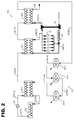
- Figure 1 is a schematic depiction of a system 100 employing a Rankine cycle using a three stage expansion system in accordance with the principles of the present disclosure.
- the system 100 employs a working fluid 12 as the working substance for closed loop circulation while using the Rankine cycle to generate mechanical work.
- the working fluid 12 can be of any type suitable for the Rankine cycle.
- the working fluid is ethanol, n-pentane, or toluene.
- the working fluid 12 is designated as different reference numerals, such as 13, 14, 17, 22, 23, 16, 27, 28, 30 and 32, to represent different phases, temperatures and/or pressures or the fluid 12.
- the system 100 includes an engine 52; a plurality of heat exchangers 18-1, 18-2, 18-3, and 18-4 (collectively designated as 18); a three stage expansion system having a plurality of expansion stages 20-1, 20-2, and 20-3 (collectively designated as 20); a condenser 25; and a fluid pump 16.
- the engine 52 can be an internal combustion engine that operates on combustion of a chemical fuel, such as diesel fuel or gasoline, and produces a great quantity of heat and exhaust gases.
- the engine 52 can include a supercharger or turbocharger 102 to use forced induction.
- the plurality of heat exchangers 18 is configured to transfer heat to and from the working fluid 12 passing therein.
- the expansion stages 20 are configured to receive the working fluid 12 and generate mechanical work. In operation, as the working fluid 12 passes through the expansion stage 20, the temperature and pressure of the fluid 12 drop. In general, the expansion stages 20 rely upon the pressure of the fluid 12 to rotate an output shaft, thereby creating mechanical energy.
- the mechanical energy can be used or stored in several ways. For example, the torque created by the expansion stages 20 can be used by the engine 52. Each of the expansion stages 20 can return the extracted energy back to the engine 52 via an output shaft 38 of the device 20 ( FIGS. 3-6 ). In other examples, the mechanical energy can be accumulated in a load storage device for subsequent release on demand.
- the mechanical energy can also be used for an electrical generator that is associated with the system 100 or for a hydraulic pump used by the engine 52, Accordingly, the volumetric fluid expansion stages 20 operate to increase the overall efficiency of the engine 52, to create useful mechanical work, and to recirculate the fluid 12. Examples of the expansion stages 20 are discussed below in further detail with reference to Figures 3-6 .
- the condenser 25 operates to condense the working fluid 12 from its gaseous state to a liquid state by cooling it.
- the fluid pump 16 is configured to pump the working fluid 12 from low to high pressure while maintaining the working fluid 12 in its liquid state.
- the engine 52 receives air through the turbo 102.
- the turbo 102 receives atmospheric air 103 at temperature T1 and a charge air cooler 104 cools the air 103 to air 106 at temperature T2 that is lower than temperature T1.
- the air 106 at temperature T2 is then delivered to and used by the engine 52 which thereafter emits exhaust gas 108 at temperature T3 that is higher than temperature T2.
- the exhaust gas 108 at temperature T3 enters a first heat exchanger 18-1.
- the heat exchanger 18-1 utilizes a fluid 14 at temperature T9 flowing therein as a cooling fluid.
- the temperature T9 is lower than the temperature T3.
- the fluid 14 is discharged from a first expansion stage 20-1.
- the first heat exchanger 18-1 circulates the fluid 14 through its coils, thereby cooling the exhaust gas 108 as it flows past the coils and simultaneously heating the fluid 14 to produce a fluid 13 at temperature T11 that is higher than the temperature T9.
- the heated fluid 13 at the temperature T11 then passes through a second expansion stage 20-2.
- the second expansion stage 20-2 receives the fluid 13 at the temperature T11 and discharges a fluid 17 at temperature T12 that is lower than T11. Furthermore, the fluid 17 has a lower pressure than the fluid 12. While reducing the temperature and pressure of the fluid 13 into the fluid 17, the second expansion stage 20-2 generates mechanical work that can be used or stored in various ways as discussed above.
- the fluid 21 at the temperature T4 then passes through a second heat exchanger 18-2, which is typically referred to as a recuperator, before flowing into the condenser 25.
- the recuperator 18-2 is placed between the third expansion stage 20-3 and the condenser 25 to further reclaim waste heat from the fluid 21 released from the third expansion stage 20-3.
- a fluid 23 exiting the recuperator 18-2 has temperature T10 that is lower than the temperature T4.
- the fluid 23 is then sent to the condenser 25 that is used to convert the fluid 23, which, in some examples, can be a mixture of gas and liquid, to a saturated liquid 31 at temperature T5.
- the temperature T5 remains substantially the same at the condenser 25, and thus the temperature T5 is substantially the same as T10.
- the fluid 31 at the temperature T5 is pumped from low to high pressure by the pump 16.
- the temperature T5 of the fluid 31 increases, as shown in the Rankine cycle of Figure 7 . Therefore, a fluid 27 discharged from the pump 16 has the temperature T13 that is higher than the temperature T5 of the fluid 31, and flows into the recuperator 18-2.
- the recuperator 18-2 utilizes the fluid 27 at the temperature T13 to take heat from the fluid 21, which is released from the third expansion stage 20-3. Accordingly, the recuperator 18-2 transfers heat from the fluid 21 at the temperature T4 to the fluid 27 at the temperature T13, thereby producing a fluid 33 at temperature T6 that is higher than the temperature T13.
- the fluid 33 flows to a third heat exchanger 18-3.
- the third heat exchanger 18-3 transfers heat from the exhaust gas 108, which is released from the first heat exchanger 18-1, to the fluid 33, thereby producing a fluid 35 at temperature T7 that is higher than T6.
- the fluid 35 thereafter flows to a fourth heat exchanger 18-4.
- the fourth heat exchanger 18-4 transfers heat from the exhaust gas 108 at the temperature T3, which flows through the fourth heat exchanger 18-4 from the engine 52, to the fluid 35 at the temperature T7. As a result, the fourth heat exchanger 18-4 produces a fluid 36 at temperature T8 that is greater than T7.
- the exhaust gas 108 is simultaneously cooled to a lower temperature than T3 as it flows through the fourth heat exchanger 18-4 and released to the atmosphere.
- the fluid 36 at the temperature T8 is received by the first expansion stage 20-1 that discharges a fluid 14 at temperature T9 that is lower than T8 and generates mechanical work as described above.
- the fluid 14 has a lower pressure than the fluid 36.
- the fluid 14 leaving the first expansion stage 20-1 at temperature T9 flows directly to the first heat exchanger 18-1 where it is re-heated directly by exhaust gas 108 supplied from the engine 52. The entire process is then repeated in a cycle as described above.
- the second heat exchanger 18-2 which is also referred to as the recuperator, the third heat exchanger 18-3, and the fourth heat exchanger 18-4 are connected in series.
- the second, third and fourth heat exchangers 18-2, 18-3 and 18-4 are replaced by one or two heat exchanger devices, which operate the same as the combination of the first, second and third heat exchangers 18-2, 18-3 and 18-4.
- FIG 2 is a schematic depiction of a second exemplary system 100 employing a Rankine cycle using a three stage expansion system in accordance with the principles of the present disclosure.
- the description for the first example is hereby incorporated by reference for the second example. Where like or similar features or elements are shown, the same reference numbers will be used where possible.
- the following description for the second example will be limited primarily to the differences between the first and second examples.
- the system 100 removes the first heat exchanger 18-1.
- the fluid 14 at the temperature T9 is discharged from the first expansion stage 20-1 and enters the first heat exchanger 18-1 before flowing into the second expansion stage 20-2.
- the fluid 14 at the temperature T9 discharged from the first expansion stage 20-1 is directly delivered to the second expansion stage 20-2.
- the exhaust gas 108 at the temperature T3 supplied from the engine 52 passes through the first heat exchanger 18-1 and the third heat exchanger 18-3 in series.
- the exhaust gas 108 at the temperature T3 flows directly from the engine 52 to the third heat exchanger 18-3.
- FIG 3 is a schematic depiction of a third exemplary system 100 employing a Rankine cycle using a three stage expansion system in accordance with the principles of the present disclosure.
- the description for the second example is hereby incorporated by reference for the third example. Where like or similar features or elements are shown, the same reference numbers will be used where possible.
- the following description for the third example will be limited primarily to the differences between the second and third examples.
- the recuperator 18-2 is directly connected to both the third heat exchanger 18-3 and the fourth heat exchanger 18-4 while the third heat exchanger 18-3 and the fourth heat exchanger 18-4 are arranged in parallel.
- the system 100 can include a splitter valve 19 (also known as a distributor valve), which operates to divide the fluid discharged from the recuperator 18-2 to flow into both the third heat exchanger 18-3 and the fourth heat exchanger 18-4 at the same time. Therefore, the fluid 33 at the temperature T6 discharged from the recuperator 18-2 is drawn into both the third heat exchanger 18-3 and the fourth heat exchanger 18-4.
- the third heat exchanger 18-3 transfers heat from the exhaust gas 108 of the engine 52 to the fluid 33, and discharges the fluid 29 at temperature T14, which is greater than the temperature T6.
- the fluid 29 flows directly to the first expansion stage 20-1.
- the fourth heat exchanger 18-4 transfers heat from the exhaust gas 108 of the engine 52 to the fluid 33, and discharges the fluid 36, which is then drawn to the first expansion stage 20-1.
- Additional examples are directed to a method of using a three stage expansion system in a Rankine cycle as described in Figures 1 and 2 .
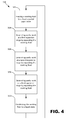
- FIG. 4 is a flowchart of an exemplary method 300 for circulating the working fluid 12 in a Rankine cycle with a three stage expansion system.
- the working fluid 12 is heated to at least a partial vapor state.
- the process can be performed by a heat exchanging device, such as the first heat exchanger 18-1, the second heat exchanger 18-2, the third heat exchanger 18-3, or the fourth heat exchanger 18-4, or any combination thereof.
- the working fluid 12 passes through the first expansion stage 20-1, which expands the working fluid 12 and generates useful work from expansion.
- the working fluid 12 discharged from the first expansion stage 20-1 passes through the second expansion stage 20-2.
- the second expansion stage 20-2 generates useful work by expanding the working fluid 12.
- the working fluid 12 is then discharged from the second expansion stage 20-2.
- the working fluid 12 passes the third expansion stage 20-3, which generates useful work by expanding the working fluid 12.
- the working fluid 14, which has been used to generate useful work by the first, second and third expansion stages 20-1, 20-2 and 20-3, is then condensed to a liquid state, and returns to the process 302.
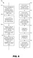
- FIG 5 is a flowchart of an exemplary method 200 for circulating the working fluid 12 in a Rankine cycle with a three stage expansion system.
- the process 200 can be performed in the system 100 in accordance with the second example described above with reference to Figure 2 .
- the working fluid 36 at the temperature T8 enters the first expansion stage 20-1 (202).
- the pressure and temperature of the working fluid 36 decrease as the working fluid 36 passes through the first expansion stage 20-1 that simultaneously generates mechanical energy, which is also referred to herein as useful work.
- the first expansion stage 20-1 then discharges the working fluid 14 at the temperature T9.
- the working fluid 14 flows into the second expansion stage 20-1 (204).
- the pressure and temperature of the working fluid 14 decrease as the working fluid 14 passes through the second expansion stage 20-2 that simultaneously generates mechanical energy.
- the second expansion stage 20-2 then discharges the working fluid 17 at the temperature T12.
- the working fluid 17 flows into the third expansion stage 20-3 (206).
- the pressure and temperature of the working fluid 17 decrease as the working fluid 17 passes through the third expansion stage 20-3 that simultaneously generates mechanical energy.
- the third expansion stage 20-3 then discharges the working fluid 21 at the temperature T4.
- the working fluid 21 enters the second heat exchanger or recuperator 18-2 (208).
- the temperature of the working fluid 21 is reduced to the temperature T10 by the recuperator 18-2.
- the working fluid 23 at the temperature T10 then enters the condenser 25, which liquidizes the fluid 23 and discharges the working fluid 31 at the temperature T5 (210).
- the temperature T5 of the fluid 31 is substantially the same as the temperature T10 of the fluid 23.
- the working fluid 31 is pumped by the pump 16.
- the working fluid 27 pumped from the pump 16 has the temperature T13 that is higher than the temperature T5 of the fluid 31, as shown in Figure 7 .
- the working fluid 27 is heated by the recuperator 18-2 to have increased temperature.
- the recuperator 18-2 produces the working fluid 33 at the temperature T6 that is higher than T13.
- the working fluid 33 is further heated by the third heat exchanger 18-3 to have increased temperature.
- the third heat exchanger 18-3 discharges the working fluid 35 at the temperature T7 higher than T6.
- the working fluid 35 is again heated by the fourth exchanger 18-4 to have increased temperature.
- the fourth heat exchanger 18-4 discharges the working fluid 36 at the temperature T8 higher than T7.
- the working fluid 36 is fed back into the third expansion stage 18-3 at process 202, as described above.
- Figure 6 is a flowchart of another exemplary method 200 for circulating a working fluid 12 in a Rankine cycle with a three stage expansion system.
- the process 200 can be performed in the system 200 in accordance with the first example described above with reference to Figure 1 .
- the description for the first example is hereby incorporated by reference for this example.
- the same reference numbers will be used where possible. The following description will be limited primarily to the differences between the first and second examples.
- the method 200 further includes a step of increasing the temperature of the working fluid at the first heat exchanger 18-1 between processes 202 and 204 (220).
- the working fluid 14 which has passed the first expansion stage 20-1, is drawn into the first heat exchanger 18-1 to increase its temperature before entering the second expansion stage 20-2.
- the temperature increases from T9 to T11.
- the first heat exchanger 18-1 discharges the working fluid 13 at the temperature T11, which subsequently flows into the second expansion stage 20-2 for process 204.
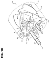
- Figures 7-12 illustrate an expander used in the system shown in Figures 1-3 .
- Figure 7 is a side perspective view of an example of a volumetric fluid expander having features that are examples of aspects in accordance with the principles of the present disclosure.
- Figure 8 is a cross-sectional side perspective view of the volumetric fluid expander shown in Figure 7 .
- Figure 9 is a cross-sectional side view of another example of a volumetric fluid expander having features that are examples of aspects in accordance with the principles of the present disclosure.
- the volumetric energy recovery device 20 relies upon the kinetic energy and static pressure of the working fluid 12-1 to rotate an output shaft 38. Where the device 20 is used in an expansion application, such as with a Rankine cycle, additional energy is extracted from the working fluid via fluid expansion. In such instances, the device 20 may be referred to as an expander or expansion device, as so presented in the following paragraphs. However, it is to be understood that the device 20 is not limited to applications where a working fluid is expanded across the device.
- the expansion device 20 has a housing 22 with a fluid inlet 24 and a fluid outlet 26 through which the working fluid 12-1 undergoes a pressure drop to transfer energy to the output shaft 38.
- the inlet port 24 is configured to admit the working fluid 12-1 at a first pressure from the heat exchanger 18 (shown in Figures 1-3 ), whereas the outlet port 26 is configured to discharge the working fluid 12-2 at a second pressure lower than the first pressure.
- the output shaft 38 is driven by synchronously connected first and second interleaved counter-rotating rotors 30, 32 which are disposed in a cavity 28 of the housing 22. Each of the rotors 30, 32 has lobes that are twisted or helically disposed along the length of the rotors 30, 32.
- the lobes Upon rotation of the rotors 30, 32, the lobes at least partially seal the working fluid 12-1 against an interior side of the housing at which point expansion of the working fluid 12-1 only occurs to the extent allowed by leakage which represents and inefficiency in the system.
- the volume defined between the lobes and the interior side of the housing 22 of device 20 is constant as the working fluid 12-1 traverses the length of the rotors 30, 32. Accordingly, the expansion device 20 may be referred to as a "volumetric device" as the sealed or partially sealed working fluid volume does not change.
- each rotor 30, 32 has four lobes, 30-1, 30-2, 30-3, and 30-4 in the case of the rotor 30, and 32-1, 32-2, 32-3, and 32-4 in the case of the rotor 32.
- each of the two rotors may have any number of lobes that is equal to or greater than two. Additionally, the number of lobes is the same for both rotors 30 and 32. This is in contrast to the construction of typical rotary screw devices and other similarly configured rotating equipment which have a dissimilar number of lobes (e.g.
- the rotors 30 and 32 are identical, wherein the rotors 30, 32 are oppositely arranged so that, as viewed from one axial end, the lobes of one rotor are twisted clockwise while the lobes of the meshing rotor are twisted counter-clockwise.
- a lobe of the rotor 32 is trailing with respect to the inlet port 24, and, therefore with respect to a stream of the high-pressure working fluid 12-1.
- first and second rotors 30 and 32 are fixed to respective rotor shafts, the first rotor being fixed to an output shaft 38 and the second rotor being fixed to a shaft 40.
- Each of the rotor shafts 38, 40 is mounted for rotation on a set of bearings (not shown) about an axis X1, X2, respectively. It is noted that axes X1 and X2 are generally parallel to each other.
- the first and second rotors 30 and 32 are interleaved and continuously meshed for unitary rotation with each other.
- the first and second rotors 30 and 32 are interleaved and continuously meshed for unitary rotation with each other.
- the expander 20 also includes meshed timing gears 42 and 44, wherein the timing gear 42 is fixed for rotation with the rotor 30, while the timing gear 44 is fixed for rotation with the rotor 32.
- the timing gears 42, 44 are also configured to maintain the relative position of the rotors 30, 32 such that contact between the rotors is entirely prevented between the rotors 30, 32 which could cause extensive damage to the rotors 30, 32. Rather, a close tolerance between the rotors 30, 32 is maintained during rotation by the timing gears 42, 44.
- a lubricant in the fluid 12 is not required for operation of the expansion device 20, in contrast to typical rotary screw devices and other similarly configured rotating equipment having rotor lobes that contact each other.
- the output shaft 38 is rotated by the working fluid 12 as the working fluid undergoes expansion from the higher first pressure working fluid 12-1 to the lower second pressure working fluid 12-2. As may additionally be seen in both Figures 9 and 10 , the output shaft 38 extends beyond the boundary of the housing 22. Accordingly, the output shaft 38 is configured to capture the work or power generated by the expander 20 during the expansion of the working fluid 12 that takes place in the rotor cavity 28 between the inlet port 24 and the outlet port 26 and transfer such work as output torque from the expander 20. Although the output shaft 38 is shown as being operatively connected to the first rotor 30, in the alternative the output shaft 38 may be operatively connected to the second rotor 32. The output shaft 38 can be coupled to the engine 52 such that the energy from the exhaust can be recaptured.
- each of the rotor lobes 30-1 to 30-4 and 32-1 to 32-4 has a lobe geometry in which the twist of each of the first and second rotors 30 and 32 is constant along their substantially matching length 34.
- one parameter of the lobe geometry is the helix angle HA.
- helix angle of the rotor lobes is meant to refer to the helix angle at the pitch diameter PD (or pitch circle) of the rotors 30 and 32.
- pitch diameter and its identification are well understood to those skilled in the gear and rotor art and will not be further discussed herein.
- the twist angle is known to those skilled in the art to be the angular displacement of the lobe, in degrees, which occurs in "traveling" the length of the lobe from the rearward end of the rotor to the forward end of the rotor. As shown, the twist angle is about 120 degrees, although the twist angle may be fewer or more degrees, such as 160 degrees.
- the inlet port 24 includes an inlet angle 24-1, as can be seen schematically at Figure 9 .
- the inlet angle 24-1 is defined as the general or average angle of an inner surface 24a of the inlet port 24, for example an anterior inner surface.
- the inlet angle 24-1 is defined as the angle of the general centerline of the inlet port 24, for example as shown at Figure 9 .
- the inlet angle 24-1 is defined as the general resulting direction of the working fluid 12-1 entering the rotors 30, 32 due to contact with the anterior inner surface 24a, as can be seen at Figure 9 .
- the inlet angle 24-1 is neither perpendicular nor parallel to the rotational axes X1, X2 of the rotors 30, 32. Accordingly, the anterior inner surface 24a of the inlet port 24 causes a substantial portion of the working fluid 12-1 to be shaped in a direction that is at an oblique angle with respect to the rotational axes X1, X2 of the rotors 30, 32, and thus generally parallel to the inlet angle 24-1.
- the inlet port 24 may be shaped such that the working fluid 12-1 is directed to the first axial ends 30a, 32a of the rotors 30, 32 and directed to the rotor lobe leading and trailing surfaces (discussed below) from a lateral direction.
- the inlet angle 24-1 may be generally parallel or generally perpendicular to axes X1, X2, although an efficiency loss may be anticipated for certain rotor configurations.
- the inlet port 24 may be shaped to narrow towards the inlet opening 24b, as shown in Figure 9 .
- the inlet port 24 has a width W that is slightly less than the combined diameter distance of the rotors 30, 32.
- the combined rotor diameter is equal to the distance between the axes X1 and X2 plus the twice the distance from the centerline axis X1 or X2 to the tip of the respective lobe.
- width W is the same as or more than the combined rotor diameter.
- the outlet port 26 includes an outlet angle 26-1, as can be seen schematically at Figure 9 .
- the outlet angle 26-1 is defined as the general or average angle of an inner surface 26a of the outlet port 26.
- the outlet angle 26-1 is defined as the angle of the general centerline of the outlet port 26, for example as shown at Figure 9 .
- the outlet angle 26-1 is defined as the general resulting direction of the working fluid 12-2 leaving the rotors 30, 32 due to contact with the inner surface 26a, as can be seen at Figure 9 .
- the outlet angle 26-1 is neither perpendicular nor parallel to the rotational axes X1, X2 of the rotors 30, 32.
- the inner surface 26a of the outlet port 26 receives the leaving working fluid 12-2 from the rotors 30, 32 at an oblique angle which can reduce backpressure at the outlet port 26.
- the inlet angle 24-1 and the outlet angle 26-1 are generally equal or parallel, as shown in Figure 9 .
- the inlet angle 24-1 and the outlet angle 26-1 are oblique with respect to each other. It is to be understood that the outlet angle 26-1 may be generally perpendicular to axes X1, X2, although an efficiency loss may be anticipated for certain rotor configurations. It is further noted that the outlet angle 26-1 may be perpendicular to the axes X1, X2.
- the orientation and size of the outlet port 26-1 are established such that the leaving working fluid 12-2 can evacuate each rotor cavity 28 as easily and rapidly as possible so that backpressure is reduced as much as possible.
- the output power of the shaft 38 is maximized to the extent that backpressure caused by the outlet can be minimized such that the working fluid can be rapidly discharged into the lower pressure working fluid at the condenser.
- the efficiency of the expander 20 can be optimized by coordinating the geometry of the inlet angle 24-1 and the geometry of the rotors 30, 32.
- the helix angle HA of the rotors 30, 32 and the inlet angle 24-1 can be configured together in a complementary fashion. Because the inlet port 24 introduces the working fluid 12-1 to both the leading and trailing faces of each rotor 30, 32, the working fluid 12-1 performs both positive and negative work on the expander 20.
- Figure 10 shows that lobes 30-1, 30-4, 32-1, and 32-2 are each exposed to the working fluid 12-1 through the inlet port opening 24b.
- Each of the lobes has a leading surface and a trailing surface, both of which are exposed to the working fluid at various points of rotation of the associated rotor.
- the leading surface is the side of the lobe that is forward most as the rotor is rotating in a direction R1, R2 while the trailing surface is the side of the lobe opposite the leading surface.
- rotor 30 rotates in direction R1 thereby resulting in side 30-1a as being the leading surface of lobe 30-1 and side 30-1b being the trailing surface.
- the leading and trailing surfaces are mirrored such that side 32-2a is the leading surface of lobe 32-2 while side 32-2b is the trailing surface.
- the working fluid 12-1 impinges on the trailing surfaces of the lobes as they pass through the inlet port opening 24b and positive work is performed on each rotor 30, 32.
- positive work it is meant that the working fluid 12-1 causes the rotors to rotate in the desired direction: direction R1 for rotor 30 and direction R2 for rotor 32.
- working fluid 12-1 will operate to impart positive work on the trailing surface 32-2b of rotor 32-2, for example on surface portion 47.
- the working fluid 12-1 is also imparting positive work on the trailing surface 30-4b of rotor 30-1, for example of surface portion 46.
- the working fluid 12-1 also impinges on the leading surfaces of the lobes, for example surfaces 30-1 and 32-1, as they pass through the inlet port opening 24b thereby causing negative work to be performed on each rotor 30, 32.
- negative work it is meant that the working fluid 12-1 causes the rotors to rotate opposite to the desired direction, R1, R2.
- One advantageous configuration for optimizing the efficiency and net positive work of the expander 20 is a rotor lobe helix angle HA of about 35 degrees and an inlet angle 24-1 of about 30 degrees.
- Such a configuration operates to maximize the impingement area of the trailing surfaces on the lobes while minimizing the impingement area of the leading surfaces of the lobes.
- the helix angle is between about 25 degrees and about 40 degrees.
- the inlet angle 24-1 is set to be within (plus or minus) 15 degrees of the helix angle.
- the helix angle is between about 25 degrees and about 40 degrees.
- the inlet angle 24-1 is set to be within (plus or minus) 15 degrees of the helix angle HA.
- the inlet angle is within (plus or minus) 10 degrees of the helix angle. In one example, the inlet angle 24-1 is set to be within (plus or minus) 5 degrees of the helix angle HA. In one example, the inlet angle 24-1 is set to be within (plus or minus) fifteen percent of the helix angle HA while in one example, the inlet angle 24-1 is within ten percent of the helix angle.
- Other inlet angle and helix angle values are possible without departing from the concepts presented herein. However, it has been found that where the values for the inlet angle and the helix angle are not sufficiently close, a significant drop in efficiency (e.g. 10-15% drop) can occur.
- Figure 13 shows a diagram 48 depicting a representative Rankine cycle applicable to the system 100, as described with respect to Figures 1-6 .
- the diagram 48 depicts different stages of the Rankine cycle showing temperature in Celsius plotted against entropy "S", wherein entropy is defined as energy in kilojoules divided by temperature in Kelvin and further divided by a kilogram of mass (kJ/kg*K).
- the Rankine cycle shown in Figure 7 is specifically a closed-loop Organic Rankine Cycle (ORC) that may use an organic, high molecular mass working fluid, with a liquid-vapor phase change, or boiling point, occurring at a lower temperature than the water-steam phase change of the classical Rankine cycle.
- the working fluid 12 may be a solvent, such as ethanol, n-pentane or toluene.
- the term " Q ⁇ " represents the heat flow to or from the system 100, and is typically expressed in energy per unit time.
- the term " ⁇ " represents mechanical power consumed by or provided to the system 100, and is also typically expressed in energy per unit time.
- stage 48-1 the working fluid 12 in the form of a wet vapor enters and passes through the condenser 25, in which the working fluid is condensed at a constant temperature to become a saturated liquid.
- the working fluid 12 is pumped from low to high pressure by the pump 16 during the stage 48-2.
- stage 48-2 the working fluid 12 is in a liquid state.
- stage 48-3 the pressurized working fluid 12 enters and passes through the heat exchanger 18 where it is heated at constant pressure by an external heat source to become a two-phase fluid, i.e., liquid together with vapor.
- stage 48-3 the working fluid 12 is transferred to stage 48-4.
- stage 48-4 the working fluid 12 in the form of the two-phase fluid expands through the expander 20, generating useful work or power. The expansion of the partially vaporized working fluid 12 through the expander 20 decreases the temperature and pressure of the two-phase fluid, such that some additional condensation of the two-phase working fluid 12 may occur.
- the working fluid 12 is returned to the condenser 25 at stage 48-1, at which point the cycle is then complete and will typically restart.
- a Rankine cycle employs a turbine configured to expand the working fluid during the stage 48-4.
- a practical Rankine cycle additionally requires a superheat boiler to take the working fluid into superheated range in order to remove or evaporate all liquid therefrom.
- a superheat boiler to take the working fluid into superheated range in order to remove or evaporate all liquid therefrom.
- Such an additional superheating process is generally required so that any liquid remaining within the working fluid will not collect at the turbine causing corrosion, pitting, and eventual failure of the turbine blades.
- the ORC of Figure 13 is characterized by the absence of such a superheat boiler and the attendant superheating process needed to evaporate all liquid from the working fluid.
- the expander 20 is configured as a twin interleafed rotor device which is not detrimentally impacted by the presence of a liquid in the working fluid 12. Furthermore, the expander 20 benefits from the presence of such a liquid, primarily because the remaining liquid tends to enhance the operational efficiency of the expander by sealing clearances between the first and second rotors 30, 32, and between the rotors and the housing 22. Accordingly, when useful work is generated by the expander 20 in the system 100, the working fluid 12 within the expander is present in two phases, i.e., as a liquid-vapor, such that conversion efficiency of the ORC is increased. However, it is to be understood that the recovery device 20 can be used in configurations involving a superheated gas.
- a smaller size expander may be used in the system 100 to achieve the required work output.
- the working fluid will likely be ethanol which has a max temp of 350c before it starts to break down.
- the expander efficiency will be less than the peak efficiency of a turbo but the efficiency islands are considerably larger over a greater flow range then than the turbo expander so an overall efficiency for a cycle is larger.
Landscapes
- Engineering & Computer Science (AREA)
- Mechanical Engineering (AREA)
- General Engineering & Computer Science (AREA)
- Chemical & Material Sciences (AREA)
- Combustion & Propulsion (AREA)
- Engine Equipment That Uses Special Cycles (AREA)
- Applications Or Details Of Rotary Compressors (AREA)
- Hydraulic Motors (AREA)
Claims (15)
- Procédé pour générer une énergie mécanique via un cycle de Rankine à boucle fermée, le procédé comprenant les étapes consistant à :faire passer un fluide de travail par un dispositif d'échange de chaleur (18) pour augmenter la température du fluide de travail ;faire passer le fluide de travail par un premier étage de détente de fluide volumétrique (20-1) pour diminuer une température et la pression du fluide de travail et pour créer une troisième énergie mécanique ;faire passer le fluide de travail par un deuxième étage de détente de fluide volumétrique (20-2) pour diminuer la température et la pression du fluide de travail et pour créer une première énergie mécanique ;faire passer le fluide de travail par un troisième étage de détente de fluide volumétrique (20-3) pour diminuer la température et la pression du fluide de travail et pour créer une deuxième énergie mécanique ;condenser le fluide de travail ; etramener le fluide de travail au premier étage de détente de fluide volumétrique (20-1) ;caractérisé en ce que chacun des premier, deuxième et troisième étages de détente de fluide volumétrique (20-1, 20-2, 20-3) comprend :un boîtier (22) avec une entrée de fluide (24) et une sortie de fluide (26) ;des premier et second rotors intercalés sans contact à rotation inverse (30, 32) disposés dans une cavité (28) du boîtier (22), chacun des rotors (30, 32) ayant des lobes qui sont droits, torsadés ou disposés de manière hélicoïdale le long de la longueur des rotors, chacun des rotors (30, 32) ayant le même nombre de lobes ; etun arbre de sortie (38) entraîné par lesdits premier et second rotors (30, 32) ;dans lequel le flux de fluide de travail est admis au niveau de l'entrée de fluide (24) à une première pression et est déchargé par l'orifice de sortie (26) à une seconde pression inférieure à la première pression, dans lequel l'écoulement du flux de fluide de travail à travers le boîtier (22) fournit la rotation des rotors (30, 32).
- Procédé selon la revendication 1, dans lequel l'étape consistant à faire passer le fluide de travail par le dispositif d'échange de chaleur comprend les étapes consistant à :recevoir, par le dispositif d'échange de chaleur (18), un flux de chaleur d'une installation électrique ; ettransférer, par le dispositif d'échange de chaleur (18), la chaleur du flux de chaleur au fluide de travail.
- Procédé selon la revendication 1, dans lequel l'étape consistant à faire passer le fluide de travail par le dispositif d'échange de chaleur comprend l'étape consistant à prévoir un premier échangeur de chaleur (18-1) agencé entre le premier étage de détente de fluide volumétrique (20-1) et le deuxième étage de détente de fluide volumétrique (20-2),
le procédé comprenant en outre l'étape consistant à :faire passer le fluide de travail par le premier échangeur de chaleur (18-1) pour augmenter la température du fluide de travail, dans lequel le premier échangeur de chaleur est configuré pour recevoir un flux de chaleur d'une installation électrique et transférer la chaleur du flux de chaleur au fluide de travail. - Procédé selon la revendication 3, comprenant en outre, après avoir condensé le fluide de travail, l'étape consistant à faire passer le fluide de travail par un deuxième échangeur de chaleur (18-2) pour augmenter la température du fluide de travail.
- Procédé selon la revendication 4, dans lequel l'étape consistant à faire passer le fluide de travail par le dispositif d'échange de chaleur comprend l'étape consistant à prévoir un troisième échangeur de chaleur (18-3) agencé en aval du deuxième échangeur de chaleur (18-2) pour recevoir le fluide de travail du deuxième échangeur de chaleur,
le procédé comprenant en outre l'étape consistant à :faire passer le fluide de travail par le troisième échangeur de chaleur (18-3) pour augmenter la température du fluide de travail, dans lequel le troisième échangeur de chaleur est configuré pour recevoir un flux de chaleur d'une installation électrique et transférer la chaleur du flux de chaleur au fluide de travail. - Procédé selon la revendication 4, dans lequel l'étape consistant à faire passer le fluide de travail par le dispositif d'échange de chaleur comprend l'étape consistant à prévoir un troisième échangeur de chaleur (18-3) agencé en aval du deuxième échangeur de chaleur (18-2) pour recevoir le fluide de travail du deuxième échangeur de chaleur,
le procédé comprenant en outre l'étape consistant à :faire passer le fluide de travail par le troisième échangeur de chaleur (18-3) pour augmenter la température du fluide de travail, dans lequel le troisième échangeur de chaleur est configuré pour recevoir le flux de chaleur du premier échangeur de chaleur (18-1) et transférer la chaleur du flux de chaleur au fluide de travail. - Procédé selon la revendication 5, dans lequel l'étape consistant à faire passer le fluide de travail par le dispositif d'échange de chaleur comprend l'étape consistant à prévoir un quatrième échangeur de chaleur (18-4) agencé en aval du troisième échangeur de chaleur (18-3) pour recevoir le fluide de travail du troisième échangeur de chaleur,
le procédé comprenant en outre l'étape consistant à :faire passer le fluide de travail par le quatrième échangeur de chaleur (18-4) pour augmenter la température du fluide de travail, dans lequel le quatrième échangeur de chaleur est configuré pour recevoir un flux de chaleur provenant d'une installation électrique et transférer la chaleur du flux de chaleur au fluide de travail. - Système utilisé pour générer de l'énergie mécanique via un cycle de Rankine à boucle fermée, le système comprenant :une installation électrique produisant un flux de chaleur et ayant une sortie de chaleur par laquelle le flux de chaleur sort ;un dispositif d'échange de chaleur (18) configuré pour transférer la chaleur du flux de chaleur à une vapeur de fluide de travail ;un premier étage de détente de fluide volumétrique (20-1) configuré pour recevoir le flux de fluide de travail du dispositif d'échange de chaleur (18) ;un deuxième étage de détente de fluide volumétrique (20-2) configuré pour recevoir le flux de fluide de travail du premier étage de détente de fluide volumétrique (20-1) ; etun troisième étage de détente de fluide volumétrique (20-3) configuré pour recevoir le flux de fluide de travail du deuxième étage de détente de fluide volumétrique (20-2) ;dans lequel chacun parmi les premier, deuxième et troisième étages de détente de fluide volumétrique (20-1, 20-2, 20-3) est configuré pour générer de l'énergie mécanique à partir du flux de fluide de travail ;caractérisé en ce que chacun des premier, deuxième et troisième étages de détente de fluide volumétrique (20-1, 20-2, 20-3) comprend :un boîtier (22) avec une entrée de fluide (24) et une sortie de fluide (26) ;des premier et second rotors entrelacés sans contact à rotation inverse (30, 32) disposés dans une cavité (28) du boîtier (22), chacun des rotors (30, 32) ayant des lobes qui sont droits, torsadés ou disposés de manière hélicoïdale le long de la longueur des rotors, chacun des rotors (30, 32) ayant le même nombre de lobes ; etun arbre de sortie (38) entraîné par lesdits premier et second rotors (30, 32) ;dans lequel le flux de fluide de travail est admis au niveau de l'entrée de fluide (24) à une première pression et est déchargé de l'orifice de sortie (26) à une seconde pression inférieure à la première pression, dans lequel l'écoulement du flux de fluide de travail par le boîtier (22) fournit la rotation des rotors (30, 32).
- Système selon la revendication 8, comprenant en outre un condenseur (25) configuré pour recevoir le fluide de travail du troisième étage de détente de fluide volumétrique (20-3) et pour condenser le fluide de travail.
- Système selon la revendication 9, comprenant en outre une pompe (16) configurée pour recevoir le fluide de travail du condenseur (25) et pour pomper le fluide de travail dans le cycle.
- Système selon la revendication 9, dans lequel le dispositif d'échange de chaleur (18) comprend un premier échangeur de chaleur (18-1) configuré pour recevoir le flux de chaleur de l'installation électrique, recevoir le fluide de travail du premier étage de détente de fluide volumétrique (20-1), transférer la chaleur du flux de chaleur à la vapeur de fluide de travail, et amener le flux de fluide de travail au deuxième étage de détente de fluide volumétrique (20-2).
- Système selon la revendication 9, dans lequel le dispositif d'échange de chaleur (18) comprend un deuxième échangeur de chaleur (18-2) configuré pour recevoir le fluide de travail déchargé du deuxième étage de détente de fluide volumétrique (20-2), dans lequel le fluide de travail sortant du deuxième échangeur de chaleur s'écoule dans le condenseur (25), le deuxième échangeur de chaleur étant en outre configuré pour recevoir le fluide de travail déchargé du condenseur et pour transférer la chaleur du fluide de travail déchargé du troisième étage de détente de fluide volumétrique (20-3) au fluide de travail déchargé du condenseur.
- Système selon la revendication 12, dans lequel le dispositif d'échange de chaleur (18) comprend un troisième échangeur de chaleur (18-3) configuré pour recevoir le flux de chaleur du premier échangeur de chaleur (18-1) et le fluide de travail du deuxième échangeur de chaleur (18-2), le troisième échangeur de chaleur étant configuré pour transférer la chaleur du flux de chaleur au fluide de travail déchargé du deuxième échangeur de chaleur.
- Système selon la revendication 13, dans lequel le dispositif d'échange de chaleur (18) comprend un quatrième échangeur de chaleur (18-4) configuré pour recevoir le flux de chaleur de l'installation électrique et le fluide de travail du troisième échangeur de chaleur (18-3), le quatrième échangeur de chaleur étant configuré pour transférer la chaleur du flux de chaleur au fluide de travail déchargé du troisième échangeur de chaleur.
- Système selon la revendication 14, dans lequel le premier étage de détente de fluide volumétrique (20-1) est agencé entre le quatrième échangeur de chaleur (18-4) et le premier échangeur de chaleur (18-1) et configuré pour recevoir le fluide de travail déchargé du quatrième échangeur de chaleur et décharger le fluide de travail dans le premier échangeur de chaleur.
Applications Claiming Priority (4)
| Application Number | Priority Date | Filing Date | Title |
|---|---|---|---|
| US201361757533P | 2013-01-28 | 2013-01-28 | |
| US201361810579P | 2013-04-10 | 2013-04-10 | |
| US201361816143P | 2013-04-25 | 2013-04-25 | |
| PCT/US2014/013393 WO2014117152A1 (fr) | 2013-01-28 | 2014-01-28 | Système volumétrique de récupération d'énergie par détente à trois étages |
Publications (2)
| Publication Number | Publication Date |
|---|---|
| EP2948647A1 EP2948647A1 (fr) | 2015-12-02 |
| EP2948647B1 true EP2948647B1 (fr) | 2016-11-16 |
Family
ID=50070725
Family Applications (2)
| Application Number | Title | Priority Date | Filing Date |
|---|---|---|---|
| EP14704724.5A Not-in-force EP2948647B1 (fr) | 2013-01-28 | 2014-01-28 | Système volumétrique de récupération d'énergie par détente à trois étages |
| EP14703515.8A Withdrawn EP2981684A1 (fr) | 2013-01-28 | 2014-01-28 | Dispositif de détente de fluide volumétrique à plusieurs étages |
Family Applications After (1)
| Application Number | Title | Priority Date | Filing Date |
|---|---|---|---|
| EP14703515.8A Withdrawn EP2981684A1 (fr) | 2013-01-28 | 2014-01-28 | Dispositif de détente de fluide volumétrique à plusieurs étages |
Country Status (4)
| Country | Link |
|---|---|
| US (2) | US20150330257A1 (fr) |
| EP (2) | EP2948647B1 (fr) |
| CN (2) | CN105209724A (fr) |
| WO (2) | WO2014117159A1 (fr) |
Families Citing this family (11)
| Publication number | Priority date | Publication date | Assignee | Title |
|---|---|---|---|---|
| US20140260245A1 (en) * | 2013-03-15 | 2014-09-18 | Eaton Corporation | Volumetric energy recovery device with variable speed drive |
| EP3008298B1 (fr) * | 2013-09-25 | 2020-11-18 | Siemens Aktiengesellschaft | Agencement et procédé pour l'utilisation de chaleur perdue |
| WO2016032737A1 (fr) * | 2014-08-28 | 2016-03-03 | Eaton Corporation | Stratégie d'efficacité optimisée pour un détendeur volumétrique multi-étages |
| CA2962461C (fr) * | 2014-09-25 | 2022-06-21 | Nuhn Industries Ltd. | Pompe a fluide munie de plusieurs tetes de pompe |
| EP3032048A1 (fr) | 2014-12-09 | 2016-06-15 | Eaton Corporation | Système à cycle de rankine organique avec circuit de lubrification |
| DE112015005857T5 (de) * | 2014-12-30 | 2017-11-16 | Eaton Corporation | Optimale Expanderauslassportierung |
| WO2016187429A1 (fr) * | 2015-05-19 | 2016-11-24 | Eaton Corporation | Configuration pour récupération optimisée de chaleur perdue |
| EP3118424B1 (fr) * | 2015-07-16 | 2020-05-20 | Orcan Energy AG | Reglages de processus orc par pulverisation d'un fluide non evapore |
| US20190113035A1 (en) | 2016-03-09 | 2019-04-18 | Eaton Intelligent Power Limited | Optimized energy recovery device rotor |
| EP3330499B1 (fr) | 2016-12-05 | 2023-08-23 | Orcan Energy AG | Système et procédé de récupération d'énergie dans des installations industrielles |
| DE102017121954A1 (de) * | 2017-09-21 | 2019-03-21 | GasNet s.r.o. | Schraubenexpander und Verfahren zum Erzeugen von mechanischer Energie durch Expandieren eines Arbeitsfluids |
Family Cites Families (27)
| Publication number | Priority date | Publication date | Assignee | Title |
|---|---|---|---|---|
| US3611718A (en) * | 1970-05-05 | 1971-10-12 | Treadwell Corp | Waste heat steam generating cycle |
| US3908381A (en) * | 1974-11-20 | 1975-09-30 | Sperry Rand Corp | Geothermal energy conversion system for maximum energy extraction |
| US4300353A (en) * | 1975-07-24 | 1981-11-17 | Ridgway Stuart L | Vehicle propulsion system |
| US4090362A (en) * | 1976-08-23 | 1978-05-23 | Bourque Robert F | External combustion power cycle and engine with combustion air preheating |
| DE2852076A1 (de) * | 1977-12-05 | 1979-06-07 | Fiat Spa | Anlage zur erzeugung mechanischer energie aus waermequellen unterschiedlicher temperatur |
| US5000003A (en) * | 1989-08-28 | 1991-03-19 | Wicks Frank E | Combined cycle engine |
| US5241817A (en) * | 1991-04-09 | 1993-09-07 | George Jr Leslie C | Screw engine with regenerative braking |
| US5327987A (en) * | 1992-04-02 | 1994-07-12 | Abdelmalek Fawzy T | High efficiency hybrid car with gasoline engine, and electric battery powered motor |
| NL9401700A (nl) * | 1994-10-14 | 1996-05-01 | Albert Bakker | Heet-gasmotor en -/compressoreenheid. |
| US5555731A (en) * | 1995-02-28 | 1996-09-17 | Rosenblatt; Joel H. | Preheated injection turbine system |
| US5605124A (en) * | 1995-11-06 | 1997-02-25 | Morgan; Christopher K. | Rotary screw internal combustion engine |
| CZ288117B6 (cs) * | 2000-02-18 | 2001-04-11 | Perna Vratislav | Zařízení se šroubovými zuby ve vzájemné interakci |
| US20070157659A1 (en) * | 2006-01-10 | 2007-07-12 | Mcphail Richard Jr | Multi-stage refrigerant turbine |
| US20100192574A1 (en) * | 2006-01-19 | 2010-08-05 | Langson Richard K | Power compounder |
| US8561405B2 (en) * | 2007-06-29 | 2013-10-22 | General Electric Company | System and method for recovering waste heat |
| US8209951B2 (en) * | 2007-08-31 | 2012-07-03 | General Electric Company | Power generation system having an exhaust attemperating device |
| US7748210B2 (en) * | 2008-07-31 | 2010-07-06 | General Electric Company | System and method for use in a combined or rankine cycle power plant |
| US20110209473A1 (en) * | 2010-02-26 | 2011-09-01 | Jassin Fritz | System and method for waste heat recovery in exhaust gas recirculation |
| CN101852092B (zh) * | 2010-04-23 | 2012-05-23 | 马重芳 | 单螺杆膨胀机气动汽车发动机动力系统 |
| DE102010034230A1 (de) * | 2010-08-07 | 2012-02-09 | Daimler Ag | Expansionsvorrichtung zur Verwendung in einem Arbeitsmittelkreislauf und Verfahren zum Betrieb einer Expansionsvorrichtung |
| US8464697B2 (en) | 2010-08-13 | 2013-06-18 | Eaton Corporation | Integrated clutch supercharger |
| ITMI20110684A1 (it) * | 2011-04-21 | 2012-10-22 | Exergy Orc S R L | Impianto e processo per la produzione di energia tramite ciclo rankine organico |
| US8302399B1 (en) * | 2011-05-13 | 2012-11-06 | General Electric Company | Organic rankine cycle systems using waste heat from charge air cooling |
| CN202250242U (zh) * | 2011-09-08 | 2012-05-30 | 上海汉钟精机股份有限公司 | 开启式双螺杆膨胀机 |
| CN102434236A (zh) * | 2011-11-17 | 2012-05-02 | 重庆川然节能技术有限公司 | 螺杆膨胀/向心涡轮低参数余热联合发电机组 |
| CN202391502U (zh) * | 2011-11-17 | 2012-08-22 | 重庆川然节能技术有限公司 | 一种螺杆膨胀/向心涡轮低参数余热联合发电机组 |
| CN203547984U (zh) | 2012-02-29 | 2014-04-16 | 伊顿公司 | 用于产生有用功的系统、体积流体膨胀器和能量回收系统 |
-
2014
- 2014-01-28 EP EP14704724.5A patent/EP2948647B1/fr not_active Not-in-force
- 2014-01-28 WO PCT/US2014/013401 patent/WO2014117159A1/fr active Application Filing
- 2014-01-28 EP EP14703515.8A patent/EP2981684A1/fr not_active Withdrawn
- 2014-01-28 CN CN201480017926.XA patent/CN105209724A/zh active Pending
- 2014-01-28 CN CN201480017829.0A patent/CN105051329A/zh active Pending
- 2014-01-28 WO PCT/US2014/013393 patent/WO2014117152A1/fr active Application Filing
-
2015
- 2015-07-28 US US14/810,726 patent/US20150330257A1/en not_active Abandoned
- 2015-07-28 US US14/810,712 patent/US20150330258A1/en not_active Abandoned
Non-Patent Citations (1)
| Title |
|---|
| None * |
Also Published As
| Publication number | Publication date |
|---|---|
| EP2981684A1 (fr) | 2016-02-10 |
| EP2948647A1 (fr) | 2015-12-02 |
| US20150330257A1 (en) | 2015-11-19 |
| US20150330258A1 (en) | 2015-11-19 |
| CN105209724A (zh) | 2015-12-30 |
| WO2014117159A1 (fr) | 2014-07-31 |
| WO2014117152A4 (fr) | 2014-09-12 |
| WO2014117152A1 (fr) | 2014-07-31 |
| CN105051329A (zh) | 2015-11-11 |
Similar Documents
| Publication | Publication Date | Title |
|---|---|---|
| EP2948647B1 (fr) | Système volumétrique de récupération d'énergie par détente à trois étages | |
| US9587521B2 (en) | Volumetric energy recovery device and systems | |
| EP2262979B1 (fr) | Génération d'énergie à partir de sources de chaleur à température moyenne | |
| CA2714761C (fr) | Installation a cycle de rankine a double postcombustion et methode connexe | |
| Karellas et al. | Supercritical fluid parameters in organic Rankine cycle applications | |
| RU2551458C2 (ru) | Комбинированная тепловая система с замкнутым контуром для рекуперации отработанного тепла и способ ее эксплуатации | |
| US7637108B1 (en) | Power compounder | |
| EP3314096B1 (fr) | Systeme et procede de production d'energie utile a partir de la chaleur fournie par une source de chaleur | |
| US20100319346A1 (en) | System for recovering waste heat | |
| US9945289B2 (en) | Organic rankine cycle for mechanical drive applications | |
| WO2008125827A2 (fr) | Appareil et procédé à cycle de rankine organique | |
| WO2010048100A2 (fr) | Moteurs à ultra haut rendement et système thermodynamique correspondant | |
| US20140260245A1 (en) | Volumetric energy recovery device with variable speed drive | |
| EP3420201B1 (fr) | Cycle en cascade de récupération de chaleur perdue et procédé | |
| WO2021034221A1 (fr) | Installation de génération électrique à gaz et vapeur selon le cycle d'anthony | |
| RU2811448C2 (ru) | Газопаровая энергетическая установка | |
| Al-Hamadani et al. | Review Of Organic Rankine Cycle Used In Small-Scale Application | |
| WO2013042141A1 (fr) | Détendeur à palette | |
| RU2811729C2 (ru) | Парогазовая энергетическая установка |
Legal Events
| Date | Code | Title | Description |
|---|---|---|---|
| PUAI | Public reference made under article 153(3) epc to a published international application that has entered the european phase |
Free format text: ORIGINAL CODE: 0009012 |
|
| 17P | Request for examination filed |
Effective date: 20150825 |
|
| AK | Designated contracting states |
Kind code of ref document: A1 Designated state(s): AL AT BE BG CH CY CZ DE DK EE ES FI FR GB GR HR HU IE IS IT LI LT LU LV MC MK MT NL NO PL PT RO RS SE SI SK SM TR |
|
| AX | Request for extension of the european patent |
Extension state: BA ME |
|
| DAX | Request for extension of the european patent (deleted) | ||
| GRAP | Despatch of communication of intention to grant a patent |
Free format text: ORIGINAL CODE: EPIDOSNIGR1 |
|
| INTG | Intention to grant announced |
Effective date: 20160621 |
|
| GRAJ | Information related to disapproval of communication of intention to grant by the applicant or resumption of examination proceedings by the epo deleted |
Free format text: ORIGINAL CODE: EPIDOSDIGR1 |
|
| GRAR | Information related to intention to grant a patent recorded |
Free format text: ORIGINAL CODE: EPIDOSNIGR71 |
|
| GRAS | Grant fee paid |
Free format text: ORIGINAL CODE: EPIDOSNIGR3 |
|
| GRAA | (expected) grant |
Free format text: ORIGINAL CODE: 0009210 |
|
| INTC | Intention to grant announced (deleted) | ||
| AK | Designated contracting states |
Kind code of ref document: B1 Designated state(s): AL AT BE BG CH CY CZ DE DK EE ES FI FR GB GR HR HU IE IS IT LI LT LU LV MC MK MT NL NO PL PT RO RS SE SI SK SM TR |
|
| INTG | Intention to grant announced |
Effective date: 20161012 |
|
| REG | Reference to a national code |
Ref country code: GB Ref legal event code: FG4D |
|
| REG | Reference to a national code |
Ref country code: CH Ref legal event code: EP |
|
| REG | Reference to a national code |
Ref country code: IE Ref legal event code: FG4D |
|
| REG | Reference to a national code |
Ref country code: AT Ref legal event code: REF Ref document number: 846159 Country of ref document: AT Kind code of ref document: T Effective date: 20161215 |
|
| REG | Reference to a national code |
Ref country code: DE Ref legal event code: R096 Ref document number: 602014004902 Country of ref document: DE |
|
| PG25 | Lapsed in a contracting state [announced via postgrant information from national office to epo] |
Ref country code: LV Free format text: LAPSE BECAUSE OF FAILURE TO SUBMIT A TRANSLATION OF THE DESCRIPTION OR TO PAY THE FEE WITHIN THE PRESCRIBED TIME-LIMIT Effective date: 20161116 |
|
| REG | Reference to a national code |
Ref country code: NL Ref legal event code: MP Effective date: 20161116 |
|
| REG | Reference to a national code |
Ref country code: LT Ref legal event code: MG4D |
|
| REG | Reference to a national code |
Ref country code: AT Ref legal event code: MK05 Ref document number: 846159 Country of ref document: AT Kind code of ref document: T Effective date: 20161116 |
|
| PG25 | Lapsed in a contracting state [announced via postgrant information from national office to epo] |
Ref country code: LT Free format text: LAPSE BECAUSE OF FAILURE TO SUBMIT A TRANSLATION OF THE DESCRIPTION OR TO PAY THE FEE WITHIN THE PRESCRIBED TIME-LIMIT Effective date: 20161116 Ref country code: NO Free format text: LAPSE BECAUSE OF FAILURE TO SUBMIT A TRANSLATION OF THE DESCRIPTION OR TO PAY THE FEE WITHIN THE PRESCRIBED TIME-LIMIT Effective date: 20170216 Ref country code: GR Free format text: LAPSE BECAUSE OF FAILURE TO SUBMIT A TRANSLATION OF THE DESCRIPTION OR TO PAY THE FEE WITHIN THE PRESCRIBED TIME-LIMIT Effective date: 20170217 Ref country code: SE Free format text: LAPSE BECAUSE OF FAILURE TO SUBMIT A TRANSLATION OF THE DESCRIPTION OR TO PAY THE FEE WITHIN THE PRESCRIBED TIME-LIMIT Effective date: 20161116 Ref country code: NL Free format text: LAPSE BECAUSE OF FAILURE TO SUBMIT A TRANSLATION OF THE DESCRIPTION OR TO PAY THE FEE WITHIN THE PRESCRIBED TIME-LIMIT Effective date: 20161116 |
|
| PGFP | Annual fee paid to national office [announced via postgrant information from national office to epo] |
Ref country code: DE Payment date: 20170131 Year of fee payment: 4 |
|
| PG25 | Lapsed in a contracting state [announced via postgrant information from national office to epo] |
Ref country code: ES Free format text: LAPSE BECAUSE OF FAILURE TO SUBMIT A TRANSLATION OF THE DESCRIPTION OR TO PAY THE FEE WITHIN THE PRESCRIBED TIME-LIMIT Effective date: 20161116 Ref country code: HR Free format text: LAPSE BECAUSE OF FAILURE TO SUBMIT A TRANSLATION OF THE DESCRIPTION OR TO PAY THE FEE WITHIN THE PRESCRIBED TIME-LIMIT Effective date: 20161116 Ref country code: AT Free format text: LAPSE BECAUSE OF FAILURE TO SUBMIT A TRANSLATION OF THE DESCRIPTION OR TO PAY THE FEE WITHIN THE PRESCRIBED TIME-LIMIT Effective date: 20161116 Ref country code: PT Free format text: LAPSE BECAUSE OF FAILURE TO SUBMIT A TRANSLATION OF THE DESCRIPTION OR TO PAY THE FEE WITHIN THE PRESCRIBED TIME-LIMIT Effective date: 20170316 Ref country code: PL Free format text: LAPSE BECAUSE OF FAILURE TO SUBMIT A TRANSLATION OF THE DESCRIPTION OR TO PAY THE FEE WITHIN THE PRESCRIBED TIME-LIMIT Effective date: 20161116 Ref country code: FI Free format text: LAPSE BECAUSE OF FAILURE TO SUBMIT A TRANSLATION OF THE DESCRIPTION OR TO PAY THE FEE WITHIN THE PRESCRIBED TIME-LIMIT Effective date: 20161116 Ref country code: BE Free format text: LAPSE BECAUSE OF NON-PAYMENT OF DUE FEES Effective date: 20170131 Ref country code: RS Free format text: LAPSE BECAUSE OF FAILURE TO SUBMIT A TRANSLATION OF THE DESCRIPTION OR TO PAY THE FEE WITHIN THE PRESCRIBED TIME-LIMIT Effective date: 20161116 |
|
| PG25 | Lapsed in a contracting state [announced via postgrant information from national office to epo] |
Ref country code: DK Free format text: LAPSE BECAUSE OF FAILURE TO SUBMIT A TRANSLATION OF THE DESCRIPTION OR TO PAY THE FEE WITHIN THE PRESCRIBED TIME-LIMIT Effective date: 20161116 Ref country code: CZ Free format text: LAPSE BECAUSE OF FAILURE TO SUBMIT A TRANSLATION OF THE DESCRIPTION OR TO PAY THE FEE WITHIN THE PRESCRIBED TIME-LIMIT Effective date: 20161116 Ref country code: RO Free format text: LAPSE BECAUSE OF FAILURE TO SUBMIT A TRANSLATION OF THE DESCRIPTION OR TO PAY THE FEE WITHIN THE PRESCRIBED TIME-LIMIT Effective date: 20161116 Ref country code: SK Free format text: LAPSE BECAUSE OF FAILURE TO SUBMIT A TRANSLATION OF THE DESCRIPTION OR TO PAY THE FEE WITHIN THE PRESCRIBED TIME-LIMIT Effective date: 20161116 Ref country code: EE Free format text: LAPSE BECAUSE OF FAILURE TO SUBMIT A TRANSLATION OF THE DESCRIPTION OR TO PAY THE FEE WITHIN THE PRESCRIBED TIME-LIMIT Effective date: 20161116 |
|
| REG | Reference to a national code |
Ref country code: DE Ref legal event code: R097 Ref document number: 602014004902 Country of ref document: DE |
|
| PG25 | Lapsed in a contracting state [announced via postgrant information from national office to epo] |
Ref country code: BE Free format text: LAPSE BECAUSE OF FAILURE TO SUBMIT A TRANSLATION OF THE DESCRIPTION OR TO PAY THE FEE WITHIN THE PRESCRIBED TIME-LIMIT Effective date: 20161116 Ref country code: SM Free format text: LAPSE BECAUSE OF FAILURE TO SUBMIT A TRANSLATION OF THE DESCRIPTION OR TO PAY THE FEE WITHIN THE PRESCRIBED TIME-LIMIT Effective date: 20161116 Ref country code: BG Free format text: LAPSE BECAUSE OF FAILURE TO SUBMIT A TRANSLATION OF THE DESCRIPTION OR TO PAY THE FEE WITHIN THE PRESCRIBED TIME-LIMIT Effective date: 20170216 Ref country code: IT Free format text: LAPSE BECAUSE OF FAILURE TO SUBMIT A TRANSLATION OF THE DESCRIPTION OR TO PAY THE FEE WITHIN THE PRESCRIBED TIME-LIMIT Effective date: 20161116 |
|
| REG | Reference to a national code |
Ref country code: CH Ref legal event code: PL |
|
| PLBE | No opposition filed within time limit |
Free format text: ORIGINAL CODE: 0009261 |
|
| STAA | Information on the status of an ep patent application or granted ep patent |
Free format text: STATUS: NO OPPOSITION FILED WITHIN TIME LIMIT |
|
| PG25 | Lapsed in a contracting state [announced via postgrant information from national office to epo] |
Ref country code: MC Free format text: LAPSE BECAUSE OF FAILURE TO SUBMIT A TRANSLATION OF THE DESCRIPTION OR TO PAY THE FEE WITHIN THE PRESCRIBED TIME-LIMIT Effective date: 20161116 |
|
| 26N | No opposition filed |
Effective date: 20170817 |
|
| REG | Reference to a national code |
Ref country code: FR Ref legal event code: ST Effective date: 20170929 |
|
| PG25 | Lapsed in a contracting state [announced via postgrant information from national office to epo] |
Ref country code: FR Free format text: LAPSE BECAUSE OF NON-PAYMENT OF DUE FEES Effective date: 20170131 Ref country code: CH Free format text: LAPSE BECAUSE OF NON-PAYMENT OF DUE FEES Effective date: 20170131 Ref country code: LI Free format text: LAPSE BECAUSE OF NON-PAYMENT OF DUE FEES Effective date: 20170131 |
|
| REG | Reference to a national code |
Ref country code: IE Ref legal event code: MM4A |
|
| PG25 | Lapsed in a contracting state [announced via postgrant information from national office to epo] |
Ref country code: LU Free format text: LAPSE BECAUSE OF NON-PAYMENT OF DUE FEES Effective date: 20170128 Ref country code: SI Free format text: LAPSE BECAUSE OF FAILURE TO SUBMIT A TRANSLATION OF THE DESCRIPTION OR TO PAY THE FEE WITHIN THE PRESCRIBED TIME-LIMIT Effective date: 20161116 |
|
| PG25 | Lapsed in a contracting state [announced via postgrant information from national office to epo] |
Ref country code: IE Free format text: LAPSE BECAUSE OF NON-PAYMENT OF DUE FEES Effective date: 20170128 |
|
| REG | Reference to a national code |
Ref country code: DE Ref legal event code: R119 Ref document number: 602014004902 Country of ref document: DE |
|
| GBPC | Gb: european patent ceased through non-payment of renewal fee |
Effective date: 20180128 |
|
| PG25 | Lapsed in a contracting state [announced via postgrant information from national office to epo] |
Ref country code: MT Free format text: LAPSE BECAUSE OF NON-PAYMENT OF DUE FEES Effective date: 20170128 |
|
| PG25 | Lapsed in a contracting state [announced via postgrant information from national office to epo] |
Ref country code: DE Free format text: LAPSE BECAUSE OF NON-PAYMENT OF DUE FEES Effective date: 20180801 |
|
| PG25 | Lapsed in a contracting state [announced via postgrant information from national office to epo] |
Ref country code: GB Free format text: LAPSE BECAUSE OF NON-PAYMENT OF DUE FEES Effective date: 20180128 |
|
| PG25 | Lapsed in a contracting state [announced via postgrant information from national office to epo] |
Ref country code: HU Free format text: LAPSE BECAUSE OF FAILURE TO SUBMIT A TRANSLATION OF THE DESCRIPTION OR TO PAY THE FEE WITHIN THE PRESCRIBED TIME-LIMIT; INVALID AB INITIO Effective date: 20140128 |
|
| PG25 | Lapsed in a contracting state [announced via postgrant information from national office to epo] |
Ref country code: CY Free format text: LAPSE BECAUSE OF FAILURE TO SUBMIT A TRANSLATION OF THE DESCRIPTION OR TO PAY THE FEE WITHIN THE PRESCRIBED TIME-LIMIT Effective date: 20161116 |
|
| PG25 | Lapsed in a contracting state [announced via postgrant information from national office to epo] |
Ref country code: MK Free format text: LAPSE BECAUSE OF FAILURE TO SUBMIT A TRANSLATION OF THE DESCRIPTION OR TO PAY THE FEE WITHIN THE PRESCRIBED TIME-LIMIT Effective date: 20161116 |
|
| PG25 | Lapsed in a contracting state [announced via postgrant information from national office to epo] |
Ref country code: TR Free format text: LAPSE BECAUSE OF FAILURE TO SUBMIT A TRANSLATION OF THE DESCRIPTION OR TO PAY THE FEE WITHIN THE PRESCRIBED TIME-LIMIT Effective date: 20161116 |
|
| PG25 | Lapsed in a contracting state [announced via postgrant information from national office to epo] |
Ref country code: AL Free format text: LAPSE BECAUSE OF FAILURE TO SUBMIT A TRANSLATION OF THE DESCRIPTION OR TO PAY THE FEE WITHIN THE PRESCRIBED TIME-LIMIT Effective date: 20161116 Ref country code: IS Free format text: LAPSE BECAUSE OF FAILURE TO SUBMIT A TRANSLATION OF THE DESCRIPTION OR TO PAY THE FEE WITHIN THE PRESCRIBED TIME-LIMIT Effective date: 20170316 |