EP2948366B1 - Ship propulsion arrangement - Google Patents
Ship propulsion arrangement Download PDFInfo
- Publication number
- EP2948366B1 EP2948366B1 EP13805885.4A EP13805885A EP2948366B1 EP 2948366 B1 EP2948366 B1 EP 2948366B1 EP 13805885 A EP13805885 A EP 13805885A EP 2948366 B1 EP2948366 B1 EP 2948366B1
- Authority
- EP
- European Patent Office
- Prior art keywords
- bearing
- stator
- shaft
- rotor
- ship
- Prior art date
- Legal status (The legal status is an assumption and is not a legal conclusion. Google has not performed a legal analysis and makes no representation as to the accuracy of the status listed.)
- Active
Links
- XLYOFNOQVPJJNP-UHFFFAOYSA-N water Substances O XLYOFNOQVPJJNP-UHFFFAOYSA-N 0.000 claims description 5
- 230000005540 biological transmission Effects 0.000 claims description 2
- 238000005461 lubrication Methods 0.000 description 2
- 238000000034 method Methods 0.000 description 2
- 238000006243 chemical reaction Methods 0.000 description 1
- 238000001816 cooling Methods 0.000 description 1
- 230000008878 coupling Effects 0.000 description 1
- 238000010168 coupling process Methods 0.000 description 1
- 238000005859 coupling reaction Methods 0.000 description 1
- 238000007599 discharging Methods 0.000 description 1
- 239000007788 liquid Substances 0.000 description 1
- 238000012423 maintenance Methods 0.000 description 1
- 239000000463 material Substances 0.000 description 1
- 210000000056 organ Anatomy 0.000 description 1
Images


Classifications
-
- B—PERFORMING OPERATIONS; TRANSPORTING
- B63—SHIPS OR OTHER WATERBORNE VESSELS; RELATED EQUIPMENT
- B63H—MARINE PROPULSION OR STEERING
- B63H5/00—Arrangements on vessels of propulsion elements directly acting on water
- B63H5/07—Arrangements on vessels of propulsion elements directly acting on water of propellers
- B63H5/14—Arrangements on vessels of propulsion elements directly acting on water of propellers characterised by being mounted in non-rotating ducts or rings, e.g. adjustable for steering purpose
-
- B—PERFORMING OPERATIONS; TRANSPORTING
- B63—SHIPS OR OTHER WATERBORNE VESSELS; RELATED EQUIPMENT
- B63H—MARINE PROPULSION OR STEERING
- B63H23/00—Transmitting power from propulsion power plant to propulsive elements
- B63H23/32—Other parts
- B63H23/321—Bearings or seals specially adapted for propeller shafts
- B63H23/326—Water lubricated bearings
-
- B—PERFORMING OPERATIONS; TRANSPORTING
- B63—SHIPS OR OTHER WATERBORNE VESSELS; RELATED EQUIPMENT
- B63H—MARINE PROPULSION OR STEERING
- B63H5/00—Arrangements on vessels of propulsion elements directly acting on water
- B63H5/07—Arrangements on vessels of propulsion elements directly acting on water of propellers
- B63H5/14—Arrangements on vessels of propulsion elements directly acting on water of propellers characterised by being mounted in non-rotating ducts or rings, e.g. adjustable for steering purpose
- B63H5/15—Nozzles, e.g. Kort-type
Definitions
- the invention relates to a ship with a drive.
- the drive comprises an engine and a propulsion device.
- the Propulsionsorgan consists of three main components: rotor, stator, nozzle.
- the nozzle encloses the rotor and the stator, which follows in the flow direction. Due to the delay characteristic of the nozzle in the area of the rotor, the pressure level is raised and thus enables a higher power density while avoiding cavitation.
- the subsequent connection of the stator leads to a Entdrallung the flow and thus to increase the generated thrust at the same input power.
- Prime mover is any type of engine into consideration, such as a diesel engine or a gas turbine and an electric motor.
- the drive is intended for fast ships with a maximum speed in the range of 25 to 40 knots, such as mega-yachts or patrol boats.
- conventional screw propellers are subject to efficiency losses due to cavitation.
- Water jets also show low efficiencies in this area, as they have high inlet channel losses.
- WO 2012/052155 A1 describes a ship with a drive comprising an engine and a Propulsionsorgan consisting of three main components: rotor, stator, nozzle.
- the nozzle encloses the rotor and the stator, which follows in the flow direction, further comprises a shaft which carries the rotor and is connected to this rotationally and shear-resistant.
- the nozzle body is divided into a front and a rear nozzle part.
- the seen in the direction of travel front nozzle part is attached to the hull.
- the rear nozzle part seen in the direction of travel is releasably attached to the hull.
- FIG. 1 one recognizes the basic structure of a ship.
- a prime mover 1 is arranged, which is designed in the present case as a diesel engine with downstream gearbox 1.1.
- the prime mover 1 can be arranged in the stern area or in the bow area of the ship or in the middle of the ship.
- a gas turbine or an electric motor can be used as well.
- Other drives are conceivable.
- the gear 1.1 is a shaft 2 in drive connection, so that torque from the engine 1 to the shaft 2 is transferable.
- the shaft 2 may consist of several individual waves which are in driving connection with each other via couplings.
- braking devices or additional gear or devices for speed and / or torque conversion between these waves can be provided.
- the predominantly horizontal shaft 2 breaks through the ship's skin and emerges from the hull, so that it runs under water in the rear. In this case, the shaft 2 may already be mounted behind the exit area.
- Such an additional support is a bearing 3, namely a so-called stern tube bearing 3.
- the stern tube bearing 3 is firmly connected to the hull.
- a rotor 5 which is rotatably and shear-resistant connected to the shaft 2.
- a stator 6 which includes a number of vanes 6.1 and a stator hub 6.2.
- Rotor 5 and stator 6 are enclosed by a nozzle body 7. This one piece. It is firmly connected to the stator via its guide vanes 6.1.
- a console 6.3 In the upper region of the nozzle body 7 is a console 6.3. This is on the one hand firmly connected to the nozzle body 7, and on the other hand, it is firmly connected to the stern of the ship and indeed in a detachable manner. See the screws 6.4
- stator 6 with its guide vanes 6.1, the stator bearing 6.2, the nozzle body 7 and the console 6.3.
- This unit can be pre-assembled and mounted in the assembled state at the rear.
- the shaft 2 and the unit can be joined together and separated from each other.
- This can be realized in that the assembly is fixed, for example, is already mounted at the rear, and that the shaft is displaceable in the direction of its longitudinal axis to the bow.
- the shaft is slidable, so the assembly can first be mounted at the rear, by mounting the console 6.3.
- the design according to the invention is particularly advantageous during assembly, since the assembly can be aligned by means of fewer screws 6.4 at the rear. This ensures that all bearing points of the shaft 2 are aligned. If the assembly is positioned, then the gap between console 6.3 and rear can be potted with a hardening liquid. After curing, the remaining screws are clamped and the assembly is mounted and aligned.
- the shaft 2 is mounted in the region of the drive machine 1 by a thrust bearing 8.
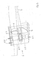
- FIG. 2 shows the stern of the ship. It can be seen again the shaft 2. Their discharging free end 2.1 is taken from the bearing bush 6.5 of the stator hub 6.2. The outer edges 5.1 of the rotor 5 are located close to the inner surface of the nozzle body 7. The vanes 6.1 are firmly connected to the inner wall of the nozzle body 7.
- Assembly and disassembly of the rotor can proceed as follows: By moving the shaft 2 in the direction of the bow, the rotor is positioned outside the nozzle. In this position, it is held in the vertical direction. By means of a corresponding device, the rotational and shear-resistant connection of the rotor 5 and shaft 2 is released. The shaft can now be moved further towards the bow and the rotor can be removed in the vertical direction. The assembly is carried out opposite to the described procedure.
- the stator hub 6.2 has a bearing bush 6.5 made of suitable material. Between the bearing bush 6.5 and the mantled surface of the shaft end 2.4 there is a bearing gap, not shown here.
- Rotor 5 generates a water flow in a known manner.
- the water flow which flows over the gap between the rotor 5 and the stator hub 6.2 induces a negative pressure.
- This negative pressure in turn generates a flow through the bearing gap in the opposite direction (internal flow) in the direction of travel. This achieves perfect lubrication and cooling.
Description
Die Erfindung betrifft ein Schiff mit einem Antrieb. Der Antrieb umfasst eine Antriebsmaschine und ein Propulsionsorgan. Das Propulsionsorgan besteht aus drei Hauptkomponenten: Rotor, Stator, Düse. Die Düse ummantelt den Rotor und den Stator, der in Strömungsrichtung folgt. Auf Grund der Verzögerungscharakteristik der Düse im Bereich des Rotors wird das Druckniveau angehoben und ermöglicht somit eine höhere Leistungsdichte bei Vermeidung von Kavitation. Die Nachschaltung des Stator führt zu einer Entdrallung der Strömung und damit zur Erhöhung des generierten Schubs bei gleicher Eingangsleistung.The invention relates to a ship with a drive. The drive comprises an engine and a propulsion device. The Propulsionsorgan consists of three main components: rotor, stator, nozzle. The nozzle encloses the rotor and the stator, which follows in the flow direction. Due to the delay characteristic of the nozzle in the area of the rotor, the pressure level is raised and thus enables a higher power density while avoiding cavitation. The subsequent connection of the stator leads to a Entdrallung the flow and thus to increase the generated thrust at the same input power.
Als Antriebsmaschine kommt dabei jede Art von Kraftmaschine in Betracht, beispielsweise ein Dieselmotor oder eine Gasturbine sowie ein Elektromotor.As a prime mover is any type of engine into consideration, such as a diesel engine or a gas turbine and an electric motor.
Der Antrieb ist für schnelle Schiffe mit einer maximalen Geschwindigkeit im Bereich von 25 bis 40 kn vorgesehen, wie beispielsweise Mega-Yachten oder Patrouillenboote. In diesem Bereich kommt es bei konventionellen Schraubenpropeller zu Wirkungsgradeinbußen im Zuge von Kavitation. Water Jets zeigen in diesem Bereich auch noch geringe Wirkungsgrade, da sie hohe Einlasskanalverluste haben.The drive is intended for fast ships with a maximum speed in the range of 25 to 40 knots, such as mega-yachts or patrol boats. In this area, conventional screw propellers are subject to efficiency losses due to cavitation. Water jets also show low efficiencies in this area, as they have high inlet channel losses.
Das in Fahrtrichtung gesehen vordere Düsenteil ist am Schiffsrumpf befestigt. Das in Fahrtrichtung gesehen hintere Düsenteil ist am Schiffsrumpf lösbar befestigt.The seen in the direction of travel front nozzle part is attached to the hull. The rear nozzle part seen in the direction of travel is releasably attached to the hull.
Sowohl bei der Erstmontage der Schiffswelle mit dem darauf sitzenden Rotor als auch bei Wartung und Inbetriebnahme muss das hintere Düsenteil zusammen mit dem von diesem getragenen Lager vom Heck her auf die Welle aufgeschoben werden. Hier muss der aus Leitschaufeln (Statorschaufeln) und Statornabe bestehende Stator in eine Position gebracht werden, dass das sich in der Statornabe befindende Statorlager mit der Welle fluchtet. Dies ist ein aufwändiges, schwieriges und zeitraubendes Manöver. Eine derartige Ausführung mit einem lösbaren, Austrittsschaufeln tragenden und von einer Düse entfernbaren Ring ist ferner aus der
- Stator, Statornabe mit integrierten Lager und der einteilige Düsenkörper bilden eine einzige vormontierte Baueinheit;
- Die Baueinheit ist mittelbar oder unmittelbar am Heck montierbar und demontierbar;
- Die Welle ist relativ zur Baueinheit in Richtung der Längsachse der Welle verfahrbar.
Figur 1- zeigt einen Längsschnitt durch den Rumpf eines Schiffes.
Figur 2- zeigt einen Längsschnitt durch den Heckbereich des Schiffes.
- Figur 3
- zeigt eine Heckansicht des Schiffes.
- Stator, stator hub with integrated bearings and the one-piece nozzle body form a single preassembled unit;
- The unit is directly or indirectly mounted and dismountable at the rear;
- The shaft is movable relative to the assembly in the direction of the longitudinal axis of the shaft.
- FIG. 1
- shows a longitudinal section through the hull of a ship.
- FIG. 2
- shows a longitudinal section through the stern of the ship.
- FIG. 3
- shows a rear view of the ship.
Aus
Im Heckbereich befindet sich ein Rotor 5, der mit der Welle 2 dreh- und schubfest verbunden ist. In Fahrrichtung gesehen hinter dem Rotor 5 befindet sich ein Stator 6. Dieser Umfasst eine Anzahl von Leitschaufeln 6.1 sowie eine Statornabe 6.2. Rotor 5 und Stator 6 sind von einem Düsenkörper 7 umschlossen. Dieser ist einteilig. Er ist mit dem Stator über dessen Leitschaufeln 6.1 fest verbunden. Im oberen Bereich des Düsenkörpers 7 befindet sich eine Konsole 6.3. Diese ist einerseits mit dem Düsenkörper 7 fest verbunden, und andererseits ist sie mit dem Heck des Schiffs fest verbindbar und zwar auf lösbare Weise. Siehe die Schrauben 6.4In the rear area is a
Die folgenden Bauteile bilden miteinander eine in montiertem Zustand feste Baueinheit: Der Stator 6 mit seinen Leitschaufeln 6.1, das Statorlager 6.2, der Düsenkörper 7 und die Konsole 6.3. Diese Baueinheit lässt sich vormontieren und in montiertem Zustand insgesamt am Heck montieren.The following components together form a fixed assembly in the assembled state: the
Außerdem sind die Welle 2 sowie die Baueinheit zusammenfügbar und voneinander trennbar. Dies kann dadurch verwirklicht werden, dass die Baueinheit fest steht, beispielsweise bereits am Heck montiert ist, und dass die Welle in Richtung ihrer Längsachse zum Bug hin verschiebbar ist. Die Welle ist verschiebbar, somit kann die Baueinheit zunächst am Heck montiert werden, und zwar durch Montage der Konsole 6.3.In addition, the
Die erfindungsgemäße Gestaltung ist bei der Montage besonders vorteilhaft, da die Baueinheit mittels weniger Schrauben 6.4 am Heck ausgerichtet werden kann. Damit wird sichergestellt, dass alle Lagerstellen der Welle 2 fluchten. Ist die Baueinheit positioniert, so kann der Zwischenraum zwischen Konsole 6.3 und Heck mit einer aushärtenden Flüssigkeit vergossen werden. Nach dem Aushärten werden die übrigen Schrauben verspannt und die Baueinheit ist montiert und ausgerichtet.The design according to the invention is particularly advantageous during assembly, since the assembly can be aligned by means of fewer screws 6.4 at the rear. This ensures that all bearing points of the
Die Welle 2 ist im Bereich der Antriebsmaschine 1 durch ein Schublager 8 gelagert.The
Montage und Demontage des Rotors können wie folgt ablaufen:
Durch Verschieben der Welle 2 in Richtung des Bugs wird der Rotor außerhalb der Düse positioniert. In dieser Position wird er in vertikaler Richtung gehalten. Mittels einer entsprechenden Vorrichtung wird die dreh- und schubfeste Verbindung von Rotor 5 und Welle 2 gelöst. Die Welle kann nun weiter in Richtung Bug verschoben werden und der Rotor in vertikaler Richtung entfernt werden.
Die Montage wird entgegengesetzt des beschriebenen Vorgangs durchgeführt.Assembly and disassembly of the rotor can proceed as follows:
By moving the
The assembly is carried out opposite to the described procedure.
Das Statornabe 6.2 weist eine Lagerbuchse 6.5 aus geeignetem Material auf. Zwischen der Lagerbuchse 6.5 und der Mantelfäche des Wellenendes 2.4 befindet sich ein her nicht gezeigter Lagerspalt.The stator hub 6.2 has a bearing bush 6.5 made of suitable material. Between the bearing bush 6.5 and the mantled surface of the shaft end 2.4 there is a bearing gap, not shown here.
Aufgrund der erfindungsgemäßen Anordnung findet ein äußerst vorteilhafter Schmiervorgang statt, der wie folgt abläuft: Rotor 5 erzeugt in bekannter Weise einen Wasserstrom. Der Wasserstrom der über den Spalt zwischen Rotor 5 und Statornabe 6.2 strömt, induziert einen Unterdruck. Dieser Unterdruck erzeugt wiederum eine Strömung durch den Lagerspalt in entgegengesetzter Richtung (Innenströmung) in Fahrtrichtung. Hierdurch wird eine perfekte Schmierung und Kühlung erreicht.Due to the arrangement according to the invention, an extremely advantageous lubrication process takes place, which proceeds as follows:
Schiffe werden klassisch mit ein bis vier Propulsionsorganen betrieben.Ships are classically operated with one to four propulsion organs.
- 11
- Antriebsmaschineprime mover
- 1.11.1
- Getriebetransmission
- 22
- Wellewave
- 2.12.1
- freies Wellenendefree shaft end
- 33
- StevenrohrlagerStern tube bearings
- 55
- Rotorrotor
- 66
- Statorstator
- 6.16.1
- Leitschaufelvane
- 6.26.2
- Statornabestator
- 6.36.3
- Konsoleconsole
- 6.46.4
- Schraubenscrew
- 6.56.5
- Lagerbuchsebearing bush
- 77
- Düsenkörpernozzle body
- 88th
- Schublagerthrust bearing
Claims (3)
- Ship, comprising the following features or components:1.1 a ship's hull, comprising a bow and a stern;1.2 a rotor (5) which is arranged in the stern region;1.3 a stator (6) which is assigned to the rotor (5), comprising a number of guide blades (6.1);1.4 a single-piece nozzle body (7);1.5 the nozzle body (7) encloses the rotor (5) and the stator (6);1.6 a propulsion machine (1) which is arranged in the bow region;1.7 a shaft (2) for the transmission of torque from the propulsion machine (1) to the rotor (5);1.8 the shaft (2) is mounted in a bearing bush (6.5) which is arranged in a stator hub (6.2), and, furthermore, in the thrust bearing (8) which is arranged in the region of the propulsion machine (1) ;characterized by the following features:1.9 the stator (6), the stator hub (6.2) and the nozzle body (7) form a single structural unit which can be pre-assembled;1.10 the structural unit can be mounted and dismantled indirectly or directly on the stern;1.11 the shaft (2) can be displaced in the direction of the longitudinal axis of the shaft (2) relative to the structural unit;1.12 the nozzle body (7) is connected fixedly to a bracket (6.3) or comprises a bracket of this type which can be mounted and dismantled on the stern of the ship's hull.
- Ship according to Claim 1, characterized in that a stern tube bearing (3) is provided as a further bearing for the shaft (2), which stern tube bearing (3) is situated between the stator bearing (6.2) and the thrust bearing (9).
- Ship according to either of Claims 1 and 2, characterized in that the stator bearing (6.2) is a water-lubricated and water-cooled bearing, comprising a bearing bush (6.5) which forms a bearing gap with the shell surface of the shaft (2), and in that the bearing gap is flushed during operation by a water stream which flows towards the bow.
Applications Claiming Priority (2)
| Application Number | Priority Date | Filing Date | Title |
|---|---|---|---|
| DE102013001372.0A DE102013001372B4 (en) | 2013-01-28 | 2013-01-28 | Assembly method for a ship propulsion |
| PCT/EP2013/076786 WO2014114410A1 (en) | 2013-01-28 | 2013-12-17 | Ship drive arrangement |
Publications (2)
| Publication Number | Publication Date |
|---|---|
| EP2948366A1 EP2948366A1 (en) | 2015-12-02 |
| EP2948366B1 true EP2948366B1 (en) | 2018-10-24 |
Family
ID=49766097
Family Applications (1)
| Application Number | Title | Priority Date | Filing Date |
|---|---|---|---|
| EP13805885.4A Active EP2948366B1 (en) | 2013-01-28 | 2013-12-17 | Ship propulsion arrangement |
Country Status (3)
| Country | Link |
|---|---|
| EP (1) | EP2948366B1 (en) |
| DE (1) | DE102013001372B4 (en) |
| WO (1) | WO2014114410A1 (en) |
Families Citing this family (1)
| Publication number | Priority date | Publication date | Assignee | Title |
|---|---|---|---|---|
| CN108929363B (en) * | 2017-05-26 | 2021-06-25 | 东莞中山大学研究院 | Preparation method of anti-cancer medicine lanosterol derivative |
Citations (3)
| Publication number | Priority date | Publication date | Assignee | Title |
|---|---|---|---|---|
| DE3508203A1 (en) * | 1985-03-08 | 1986-09-11 | Rudolf Dr. 6800 Mannheim Wieser | Marine propulsion |
| EP1878656A1 (en) * | 2006-07-10 | 2008-01-16 | Solas Science & Engineering Co., Ltd. | High efficiency watercraft propulsion system |
| WO2012052155A1 (en) * | 2010-10-19 | 2012-04-26 | Voith Patent Gmbh | Ship having a drive |
Family Cites Families (10)
| Publication number | Priority date | Publication date | Assignee | Title |
|---|---|---|---|---|
| DE1098390B (en) * | 1958-09-26 | 1961-01-26 | Muetzelfeldwerft G M B H | Surface rudder for screw ships |
| US3111108A (en) * | 1962-05-03 | 1963-11-19 | Bell Aerospace Corp | Propulsion unit |
| GB1131611A (en) * | 1964-10-27 | 1968-10-23 | Hydroconic Ltd | Improvements in or relating to the steering of vessels fitted with propulsion nozzles |
| US3336752A (en) * | 1965-07-16 | 1967-08-22 | Buehler Corp | Jet boat propulsion unit |
| US3849982A (en) * | 1972-04-03 | 1974-11-26 | Hall Marine Corp | Marine jet propulsion apparatus |
| DK0626918T3 (en) * | 1992-02-27 | 1999-06-07 | Indrive Corp | Jet propulsion unit with ship nozzle propeller |
| SE9203847L (en) * | 1992-12-21 | 1994-01-24 | Bofors Underwater Syst Ab | Propulsion device for vehicles in water |
| JPH1170894A (en) * | 1997-08-29 | 1999-03-16 | Kawasaki Heavy Ind Ltd | Shaft structure of water jet propeller |
| US6902452B1 (en) * | 2002-11-23 | 2005-06-07 | Richard S. Knight | Marine split bearings with right angle removeable grooved retainer covers |
| DE202009009899U1 (en) * | 2009-07-23 | 2010-12-02 | Becker Marine Systems Gmbh & Co. Kg | Nozzle propellers for ships |
-
2013
- 2013-01-28 DE DE102013001372.0A patent/DE102013001372B4/en active Active
- 2013-12-17 WO PCT/EP2013/076786 patent/WO2014114410A1/en active Application Filing
- 2013-12-17 EP EP13805885.4A patent/EP2948366B1/en active Active
Patent Citations (3)
| Publication number | Priority date | Publication date | Assignee | Title |
|---|---|---|---|---|
| DE3508203A1 (en) * | 1985-03-08 | 1986-09-11 | Rudolf Dr. 6800 Mannheim Wieser | Marine propulsion |
| EP1878656A1 (en) * | 2006-07-10 | 2008-01-16 | Solas Science & Engineering Co., Ltd. | High efficiency watercraft propulsion system |
| WO2012052155A1 (en) * | 2010-10-19 | 2012-04-26 | Voith Patent Gmbh | Ship having a drive |
Also Published As
| Publication number | Publication date |
|---|---|
| WO2014114410A1 (en) | 2014-07-31 |
| DE102013001372A1 (en) | 2014-07-31 |
| EP2948366A1 (en) | 2015-12-02 |
| DE102013001372B4 (en) | 2018-02-15 |
Similar Documents
| Publication | Publication Date | Title |
|---|---|---|
| DE602004012272T2 (en) | AIRCRAFT GAS TURBINE DEVICE | |
| EP2202152B1 (en) | Airplane with a rear propeller engine assembly | |
| DE102009040471B4 (en) | Mechanically propelled ship propulsor with high efficiency | |
| EP2152571B1 (en) | Rudder propeller drive, and rudder propeller driving method | |
| EP0935553B1 (en) | Dual propeller propulsion system for a water craft | |
| DE2801374C2 (en) | Gas turbine engine with tail fan | |
| DE1915533A1 (en) | Mixer arrangement | |
| DE3731463A1 (en) | AIR INLET FOR A TURBOPROP GAS TURBINE ENGINE | |
| DE1302418B (en) | ||
| EP2948366B1 (en) | Ship propulsion arrangement | |
| WO2012052155A1 (en) | Ship having a drive | |
| DE3722530A1 (en) | TURBINE ENGINE | |
| EP2223853A1 (en) | Fluid dynamic area with a turbine driven by the flow induced by the area subject to the flow | |
| DE1506372A1 (en) | Additional thrust generator on watercraft | |
| DE10158320A1 (en) | Drive system for ship has pod outside hull with central body held on flow straightening vanes and containing electric motor driving ducted propeller to produce water jet | |
| DE19541746C2 (en) | Drive device | |
| DE1808637A1 (en) | Propeller system | |
| EP1306301B1 (en) | Device for counteracting hub vortex cavitation of propellers and/or marine propulsion units | |
| DE10044101A1 (en) | Drive for fast watercraft | |
| DE2242320C3 (en) | Drive for an axial flow impeller pump | |
| DE2838392A1 (en) | Fan type thrust generator - has radial air ducts from hub through blades to gap inside shroud and vortex generator installed along shroud leading edge | |
| CH401626A (en) | Hydrodynamic torque converter | |
| DE2610257B1 (en) | Outdrive gearing for ship - with worm reduction gearing between high speed vertical shaft and horizontal hub | |
| DE1556835C (en) | Bow steering device for a ship | |
| DE1526801A1 (en) | Dual-circuit gas turbine jet engine, especially for propulsion for aircraft |
Legal Events
| Date | Code | Title | Description |
|---|---|---|---|
| PUAI | Public reference made under article 153(3) epc to a published international application that has entered the european phase |
Free format text: ORIGINAL CODE: 0009012 |
|
| 17P | Request for examination filed |
Effective date: 20150828 |
|
| AK | Designated contracting states |
Kind code of ref document: A1 Designated state(s): AL AT BE BG CH CY CZ DE DK EE ES FI FR GB GR HR HU IE IS IT LI LT LU LV MC MK MT NL NO PL PT RO RS SE SI SK SM TR |
|
| AX | Request for extension of the european patent |
Extension state: BA ME |
|
| RIN1 | Information on inventor provided before grant (corrected) |
Inventor name: PALM, MICHAEL Inventor name: JUERGENS, DIRK Inventor name: BENDL, DAVID |
|
| DAX | Request for extension of the european patent (deleted) | ||
| 17Q | First examination report despatched |
Effective date: 20170405 |
|
| GRAP | Despatch of communication of intention to grant a patent |
Free format text: ORIGINAL CODE: EPIDOSNIGR1 |
|
| INTG | Intention to grant announced |
Effective date: 20180614 |
|
| GRAJ | Information related to disapproval of communication of intention to grant by the applicant or resumption of examination proceedings by the epo deleted |
Free format text: ORIGINAL CODE: EPIDOSDIGR1 |
|
| GRAJ | Information related to disapproval of communication of intention to grant by the applicant or resumption of examination proceedings by the epo deleted |
Free format text: ORIGINAL CODE: EPIDOSDIGR1 |
|
| GRAP | Despatch of communication of intention to grant a patent |
Free format text: ORIGINAL CODE: EPIDOSNIGR1 |
|
| GRAR | Information related to intention to grant a patent recorded |
Free format text: ORIGINAL CODE: EPIDOSNIGR71 |
|
| GRAS | Grant fee paid |
Free format text: ORIGINAL CODE: EPIDOSNIGR3 |
|
| GRAA | (expected) grant |
Free format text: ORIGINAL CODE: 0009210 |
|
| INTC | Intention to grant announced (deleted) | ||
| INTG | Intention to grant announced |
Effective date: 20180912 |
|
| AK | Designated contracting states |
Kind code of ref document: B1 Designated state(s): AL AT BE BG CH CY CZ DE DK EE ES FI FR GB GR HR HU IE IS IT LI LT LU LV MC MK MT NL NO PL PT RO RS SE SI SK SM TR |
|
| REG | Reference to a national code |
Ref country code: CH Ref legal event code: EP |
|
| REG | Reference to a national code |
Ref country code: IE Ref legal event code: FG4D Free format text: LANGUAGE OF EP DOCUMENT: GERMAN |
|
| REG | Reference to a national code |
Ref country code: AT Ref legal event code: REF Ref document number: 1056360 Country of ref document: AT Kind code of ref document: T Effective date: 20181115 |
|
| REG | Reference to a national code |
Ref country code: DE Ref legal event code: R096 Ref document number: 502013011444 Country of ref document: DE |
|
| REG | Reference to a national code |
Ref country code: NL Ref legal event code: FP |
|
| REG | Reference to a national code |
Ref country code: LT Ref legal event code: MG4D |
|
| PG25 | Lapsed in a contracting state [announced via postgrant information from national office to epo] |
Ref country code: LV Free format text: LAPSE BECAUSE OF FAILURE TO SUBMIT A TRANSLATION OF THE DESCRIPTION OR TO PAY THE FEE WITHIN THE PRESCRIBED TIME-LIMIT Effective date: 20181024 Ref country code: FI Free format text: LAPSE BECAUSE OF FAILURE TO SUBMIT A TRANSLATION OF THE DESCRIPTION OR TO PAY THE FEE WITHIN THE PRESCRIBED TIME-LIMIT Effective date: 20181024 Ref country code: LT Free format text: LAPSE BECAUSE OF FAILURE TO SUBMIT A TRANSLATION OF THE DESCRIPTION OR TO PAY THE FEE WITHIN THE PRESCRIBED TIME-LIMIT Effective date: 20181024 Ref country code: PL Free format text: LAPSE BECAUSE OF FAILURE TO SUBMIT A TRANSLATION OF THE DESCRIPTION OR TO PAY THE FEE WITHIN THE PRESCRIBED TIME-LIMIT Effective date: 20181024 Ref country code: NO Free format text: LAPSE BECAUSE OF FAILURE TO SUBMIT A TRANSLATION OF THE DESCRIPTION OR TO PAY THE FEE WITHIN THE PRESCRIBED TIME-LIMIT Effective date: 20190124 Ref country code: BG Free format text: LAPSE BECAUSE OF FAILURE TO SUBMIT A TRANSLATION OF THE DESCRIPTION OR TO PAY THE FEE WITHIN THE PRESCRIBED TIME-LIMIT Effective date: 20190124 Ref country code: HR Free format text: LAPSE BECAUSE OF FAILURE TO SUBMIT A TRANSLATION OF THE DESCRIPTION OR TO PAY THE FEE WITHIN THE PRESCRIBED TIME-LIMIT Effective date: 20181024 Ref country code: IS Free format text: LAPSE BECAUSE OF FAILURE TO SUBMIT A TRANSLATION OF THE DESCRIPTION OR TO PAY THE FEE WITHIN THE PRESCRIBED TIME-LIMIT Effective date: 20190224 Ref country code: ES Free format text: LAPSE BECAUSE OF FAILURE TO SUBMIT A TRANSLATION OF THE DESCRIPTION OR TO PAY THE FEE WITHIN THE PRESCRIBED TIME-LIMIT Effective date: 20181024 |
|
| PG25 | Lapsed in a contracting state [announced via postgrant information from national office to epo] |
Ref country code: GR Free format text: LAPSE BECAUSE OF FAILURE TO SUBMIT A TRANSLATION OF THE DESCRIPTION OR TO PAY THE FEE WITHIN THE PRESCRIBED TIME-LIMIT Effective date: 20190125 Ref country code: PT Free format text: LAPSE BECAUSE OF FAILURE TO SUBMIT A TRANSLATION OF THE DESCRIPTION OR TO PAY THE FEE WITHIN THE PRESCRIBED TIME-LIMIT Effective date: 20190224 Ref country code: RS Free format text: LAPSE BECAUSE OF FAILURE TO SUBMIT A TRANSLATION OF THE DESCRIPTION OR TO PAY THE FEE WITHIN THE PRESCRIBED TIME-LIMIT Effective date: 20181024 Ref country code: SE Free format text: LAPSE BECAUSE OF FAILURE TO SUBMIT A TRANSLATION OF THE DESCRIPTION OR TO PAY THE FEE WITHIN THE PRESCRIBED TIME-LIMIT Effective date: 20181024 Ref country code: AL Free format text: LAPSE BECAUSE OF FAILURE TO SUBMIT A TRANSLATION OF THE DESCRIPTION OR TO PAY THE FEE WITHIN THE PRESCRIBED TIME-LIMIT Effective date: 20181024 |
|
| REG | Reference to a national code |
Ref country code: DE Ref legal event code: R097 Ref document number: 502013011444 Country of ref document: DE |
|
| PG25 | Lapsed in a contracting state [announced via postgrant information from national office to epo] |
Ref country code: CZ Free format text: LAPSE BECAUSE OF FAILURE TO SUBMIT A TRANSLATION OF THE DESCRIPTION OR TO PAY THE FEE WITHIN THE PRESCRIBED TIME-LIMIT Effective date: 20181024 Ref country code: DK Free format text: LAPSE BECAUSE OF FAILURE TO SUBMIT A TRANSLATION OF THE DESCRIPTION OR TO PAY THE FEE WITHIN THE PRESCRIBED TIME-LIMIT Effective date: 20181024 |
|
| REG | Reference to a national code |
Ref country code: CH Ref legal event code: PL |
|
| PG25 | Lapsed in a contracting state [announced via postgrant information from national office to epo] |
Ref country code: SM Free format text: LAPSE BECAUSE OF FAILURE TO SUBMIT A TRANSLATION OF THE DESCRIPTION OR TO PAY THE FEE WITHIN THE PRESCRIBED TIME-LIMIT Effective date: 20181024 Ref country code: EE Free format text: LAPSE BECAUSE OF FAILURE TO SUBMIT A TRANSLATION OF THE DESCRIPTION OR TO PAY THE FEE WITHIN THE PRESCRIBED TIME-LIMIT Effective date: 20181024 Ref country code: LU Free format text: LAPSE BECAUSE OF NON-PAYMENT OF DUE FEES Effective date: 20181217 Ref country code: SK Free format text: LAPSE BECAUSE OF FAILURE TO SUBMIT A TRANSLATION OF THE DESCRIPTION OR TO PAY THE FEE WITHIN THE PRESCRIBED TIME-LIMIT Effective date: 20181024 Ref country code: MC Free format text: LAPSE BECAUSE OF FAILURE TO SUBMIT A TRANSLATION OF THE DESCRIPTION OR TO PAY THE FEE WITHIN THE PRESCRIBED TIME-LIMIT Effective date: 20181024 Ref country code: RO Free format text: LAPSE BECAUSE OF FAILURE TO SUBMIT A TRANSLATION OF THE DESCRIPTION OR TO PAY THE FEE WITHIN THE PRESCRIBED TIME-LIMIT Effective date: 20181024 |
|
| PLBE | No opposition filed within time limit |
Free format text: ORIGINAL CODE: 0009261 |
|
| STAA | Information on the status of an ep patent application or granted ep patent |
Free format text: STATUS: NO OPPOSITION FILED WITHIN TIME LIMIT |
|
| REG | Reference to a national code |
Ref country code: IE Ref legal event code: MM4A |
|
| 26N | No opposition filed |
Effective date: 20190725 |
|
| REG | Reference to a national code |
Ref country code: BE Ref legal event code: MM Effective date: 20181231 |
|
| PG25 | Lapsed in a contracting state [announced via postgrant information from national office to epo] |
Ref country code: SI Free format text: LAPSE BECAUSE OF FAILURE TO SUBMIT A TRANSLATION OF THE DESCRIPTION OR TO PAY THE FEE WITHIN THE PRESCRIBED TIME-LIMIT Effective date: 20181024 Ref country code: FR Free format text: LAPSE BECAUSE OF NON-PAYMENT OF DUE FEES Effective date: 20181224 Ref country code: IE Free format text: LAPSE BECAUSE OF NON-PAYMENT OF DUE FEES Effective date: 20181217 |
|
| PG25 | Lapsed in a contracting state [announced via postgrant information from national office to epo] |
Ref country code: BE Free format text: LAPSE BECAUSE OF NON-PAYMENT OF DUE FEES Effective date: 20181231 |
|
| PG25 | Lapsed in a contracting state [announced via postgrant information from national office to epo] |
Ref country code: LI Free format text: LAPSE BECAUSE OF NON-PAYMENT OF DUE FEES Effective date: 20181231 Ref country code: CH Free format text: LAPSE BECAUSE OF NON-PAYMENT OF DUE FEES Effective date: 20181231 |
|
| PG25 | Lapsed in a contracting state [announced via postgrant information from national office to epo] |
Ref country code: MT Free format text: LAPSE BECAUSE OF FAILURE TO SUBMIT A TRANSLATION OF THE DESCRIPTION OR TO PAY THE FEE WITHIN THE PRESCRIBED TIME-LIMIT Effective date: 20181024 |
|
| REG | Reference to a national code |
Ref country code: AT Ref legal event code: MM01 Ref document number: 1056360 Country of ref document: AT Kind code of ref document: T Effective date: 20181217 |
|
| PG25 | Lapsed in a contracting state [announced via postgrant information from national office to epo] |
Ref country code: TR Free format text: LAPSE BECAUSE OF FAILURE TO SUBMIT A TRANSLATION OF THE DESCRIPTION OR TO PAY THE FEE WITHIN THE PRESCRIBED TIME-LIMIT Effective date: 20181024 |
|
| PG25 | Lapsed in a contracting state [announced via postgrant information from national office to epo] |
Ref country code: AT Free format text: LAPSE BECAUSE OF NON-PAYMENT OF DUE FEES Effective date: 20181217 |
|
| PGFP | Annual fee paid to national office [announced via postgrant information from national office to epo] |
Ref country code: GB Payment date: 20191220 Year of fee payment: 7 |
|
| PG25 | Lapsed in a contracting state [announced via postgrant information from national office to epo] |
Ref country code: MK Free format text: LAPSE BECAUSE OF NON-PAYMENT OF DUE FEES Effective date: 20181024 Ref country code: HU Free format text: LAPSE BECAUSE OF FAILURE TO SUBMIT A TRANSLATION OF THE DESCRIPTION OR TO PAY THE FEE WITHIN THE PRESCRIBED TIME-LIMIT; INVALID AB INITIO Effective date: 20131217 Ref country code: CY Free format text: LAPSE BECAUSE OF FAILURE TO SUBMIT A TRANSLATION OF THE DESCRIPTION OR TO PAY THE FEE WITHIN THE PRESCRIBED TIME-LIMIT Effective date: 20181024 |
|
| PGFP | Annual fee paid to national office [announced via postgrant information from national office to epo] |
Ref country code: IT Payment date: 20201224 Year of fee payment: 8 |
|
| GBPC | Gb: european patent ceased through non-payment of renewal fee |
Effective date: 20201217 |
|
| PG25 | Lapsed in a contracting state [announced via postgrant information from national office to epo] |
Ref country code: GB Free format text: LAPSE BECAUSE OF NON-PAYMENT OF DUE FEES Effective date: 20201217 |
|
| PG25 | Lapsed in a contracting state [announced via postgrant information from national office to epo] |
Ref country code: IT Free format text: LAPSE BECAUSE OF NON-PAYMENT OF DUE FEES Effective date: 20211217 |
|
| PGFP | Annual fee paid to national office [announced via postgrant information from national office to epo] |
Ref country code: NL Payment date: 20231220 Year of fee payment: 11 Ref country code: DE Payment date: 20231214 Year of fee payment: 11 |