EP2947784A1 - Appareil et procédé pour la transmission de signaux de données - Google Patents
Appareil et procédé pour la transmission de signaux de données Download PDFInfo
- Publication number
- EP2947784A1 EP2947784A1 EP15161524.2A EP15161524A EP2947784A1 EP 2947784 A1 EP2947784 A1 EP 2947784A1 EP 15161524 A EP15161524 A EP 15161524A EP 2947784 A1 EP2947784 A1 EP 2947784A1
- Authority
- EP
- European Patent Office
- Prior art keywords
- data signals
- pulsed
- electric
- signal
- transmission
- Prior art date
- Legal status (The legal status is an assumption and is not a legal conclusion. Google has not performed a legal analysis and makes no representation as to the accuracy of the status listed.)
- Withdrawn
Links
Images


Classifications
-
- H—ELECTRICITY
- H04—ELECTRIC COMMUNICATION TECHNIQUE
- H04B—TRANSMISSION
- H04B3/00—Line transmission systems
- H04B3/54—Systems for transmission via power distribution lines
-
- H—ELECTRICITY
- H04—ELECTRIC COMMUNICATION TECHNIQUE
- H04B—TRANSMISSION
- H04B1/00—Details of transmission systems, not covered by a single one of groups H04B3/00 - H04B13/00; Details of transmission systems not characterised by the medium used for transmission
- H04B1/69—Spread spectrum techniques
- H04B1/7163—Spread spectrum techniques using impulse radio
-
- H—ELECTRICITY
- H04—ELECTRIC COMMUNICATION TECHNIQUE
- H04B—TRANSMISSION
- H04B3/00—Line transmission systems
- H04B3/54—Systems for transmission via power distribution lines
- H04B3/542—Systems for transmission via power distribution lines the information being in digital form
-
- H—ELECTRICITY
- H04—ELECTRIC COMMUNICATION TECHNIQUE
- H04B—TRANSMISSION
- H04B2203/00—Indexing scheme relating to line transmission systems
- H04B2203/54—Aspects of powerline communications not already covered by H04B3/54 and its subgroups
- H04B2203/5404—Methods of transmitting or receiving signals via power distribution lines
- H04B2203/5425—Methods of transmitting or receiving signals via power distribution lines improving S/N by matching impedance, noise reduction, gain control
Definitions
- Forms of embodiment described here concern a method and an apparatus for transmitting data signals through electric lines.
- forms of embodiment described here can be used in various fields in the state of the art to generate an analog signal and to carry a stream of digital data in said analog signal to be transmitted by means of electric lines.
- Forms of embodiment described here can be applied, by way of non-restrictive example, in domestic, residential and industrial remote command and control systems with high robustness, such as for example domotic devices, or remote automation, or to control electric loads and the accurate management of lighting plants or electric actuation of accessories.
- the present invention is also applied in vehicles, in industrial fields, for the transmission of data on means of transport such as automobiles, trains, planes and ships.
- PLC power line communications
- PLC technologies provide to superimpose a telecommunication signal with high frequency and low amplitude over a high-voltage feed signal used to distribute the electric power, or network signal.
- Known PLC technologies also provide to use transceivers configured to reconstruct the information transmitted, filtering the feed signal and processing the telecommunication signal.
- the frequency of the feed signal is known to be equal to 50 Hz and the power of the signal supplied by PLC technologies is low, in order to satisfy legislative limits in terms of electromagnetic compatibility, to prevent interference with other devices connected to the electric network and to guarantee the correct functioning of the latter.
- Narrowband PLC technologies operate in the frequency range below 500 kHz
- broadband PLC technologies normally operate in the frequency range comprised between 1.6 MHz and 100 MHz. Extensions to bands above 100 MHz are possible, however.
- narrowband PLC technology is used for low speed communications, that is, with a data transmission speed, also known as "data rate", less than one Megabit per second, and possibly high robustness.
- data rate a data transmission speed
- An example of a narrowband PLC technology application is remote reading of meters. In the case of electric energy, remote reading allows the service provider to monitor consumption, interrogating the user's electricity meter remotely. The meter is read for example once or a few times per month and the quantity of data for every reading is limited to a few bits. Therefore, the data rate required for every user is very low.
- narrowband PLC technology application is the remote control of cut-off devices located in transformer substations of the electric network or renewable generation plants. In this case too, the transmission speed is very low, but low latencies and high robustness are required.
- narrowband PLC technology is suitable to satisfy needs of so-called “Smart Grid” applications, where Smart Grid means the combination of solutions intended for the smart management of devices for the production and consumption of electric energy.
- broadband PLC technology can offer transmission speeds of hundreds of Megabits per second, and therefore similar to those of other cabled communication solutions, such as the local network or Ethernet.
- Document WO-A-2004/021658 describes an information encoding method that uses a pair of bipolar pulses, with the same shape and amplitude but the opposite sign, which transmitted in defined and consecutive periods allow to decode and detect possible errors introduced by the communication mean.
- Broadband PLC technology can also be used in combination with wireless technologies, to obtain extensive cover.
- Attenuation is responsible for the reduction in amplitude of the signal received, and is imputable to the structure of the electric network and the nature of conductors. Fading phenomena are generated by disadaptations, such as the presence of joints, and lead to multiple copies of the signal transmitted being received, which are out of phase and distorted with respect to each other and to the original signal.
- noise is caused by a multitude of factors, such as the activity of household goods, radio disturbances captured by the electric network, etc. A loud noise can have destructive effects and make communication impossible if suitable strategies are not adopted to contrast it.
- Solutions based on currently standardized narrowband PLC technologies are based on multi-bearing modulation patterns, such as orthogonal frequency division multiplexing (OFDM), or single-bearer but narrowband modulations, such as frequency shift keying (FSK) modulation.
- OFDM orthogonal frequency division multiplexing
- FSK frequency shift keying
- One requirement of the transmitters used for generating signals in multi-bearer modulations is to have a linear behavior and low distortion. This entails high implementation costs and design complexity.
- narrowband PLC technologies are particularly sensitive to the strong criticalities of the mean in the band where they are obliged to operate.
- broadband technologies have the advantage that they can exploit the difference in frequency of the transmission mean and overcome the limits due to strong narrowband interferences or strongly attenuated spectrum windows, by transmitting in the remaining portions of the spectrum.
- document GB-A-2.393.370 proposes a method for UWB transmission at frequencies above GHz and such that the transmitter and the receiver can, in general, be antennas coupled with the conductors of the electric lines. In this case, propagation occurs between the conductors and the ground plane, exploiting signals in the common way.
- Document US-A-2010/0296550 is also known, which proposes to use block precoding techniques in combination with PAM-PPM modulation techniques for radio UWB applications or on optical guides.
- document GB-A-2.383.724 is also known, which describes a multi-conductor communication system that exploits the spatial diversity given by inductive couplings between adjacent conductors.
- one purpose of the present invention is to perfect a method for transmitting data signals, through electric lines, on a much bigger band than the data rate of the stream of digital information, which is able to guarantee transmission robustness and reliability even in the presence of strong attenuations and marked fading phenomena due to the imperfections of the transmission mean.
- Another purpose of the present invention is to exploit the phenomena of conducted propagation instead of radiated propagation which affect the highest frequencies, above GHz, and to exploit signals in differential mode instead of common mode.
- Another purpose of the present invention is to perfect a method for transmitting data signals through electric lines that is able to confer on the signals transmitted immunity both with respect to the background noise and also to the pulsed noise present in the electric lines themselves.
- Another purpose of the present invention is to perfect a transmission method that is able to adapt the data signals transmitted to the input impedance of an electric network, to limit possible losses due to disadaptation, that is usable for transmission both on alternate current (AC) networks and on direct current (DC) networks, and which is able to identify and exploit the spectrum portion most suitable for transmission.
- AC alternate current
- DC direct current
- Another purpose of the present invention is to obtain an apparatus that is able to generate data signals transmittable through electric networks and modulated according to the transmission method described above, and which, with respect to existing solutions, is simpler to make and advantageous from the point of view of implementation and costs.
- Another purpose of the present invention is to adapt the data signals transmitted to the input impedance of an electric network in order to maximize the transmission speed and robustness of the transmission system.
- Another purpose of the present invention is to transmit on several pairs of conductors, to obtain a multiple-input, multiple-output transmission that exploits temporal space precoding techniques.
- the Applicant has devised, tested and embodied the present invention to overcome the shortcomings of the state of the art and to obtain these and other purposes and advantages.
- a method according to the present invention is used for transmitting, through an electric network, one or more digital information streams containing data relating to information to be transmitted.
- the method comprises a signal generating step that generates one or more data signals and a coupling and transmission step of the one or more data signals.
- the signal generating step is a step of generating a pulsed signal that comprises one or more modulation operations and one or more filtering operations in which the digital information stream is converted into the one or more data signals, wherein the one or more data signals are generated as pulsed analog data signals defined by an alternate succession of pulsed wave forms and periods without a signal, and in which the one or more data signals are adapted to the characteristics of the transmission mean defined by the electric network.
- the information can therefore be transmitted through pulsed analog signals in which the periods without a signal allow to deal with the dispersion over time caused by the multiple path propagation phenomena that cause fading.
- the signal generating step provides to generate broadband pulsed data signals with respect to the data transmission speed of the one or more digital information streams and adapted to the conditions of the channel, the noise and the line impedance, in order to maximize performance, for example in terms of signal-noise ratio to a receiver.
- Using broadband advantageously allows to exploit the difference in frequency of the data signals to offer greater robustness to the transmission.
- the transmission method thus obtained allows very robust communications and lends itself to use, for example, for remote automation of transformer substations of the electric energy distribution network, or automation in an industrial context.
- the method according to the present invention includes a processing step of each digital information stream to obtain a corresponding encoded digital stream.
- the processing step also comprises at least one channel pre-coding step, which provides to increase the redundancy of the digital information streams. The redundancy thus obtained confers more robustness on the transmission of the pulsed data signals.
- the processing step comprises at least a power pre-coding and mapping stage, which provides to encode each information symbol of the digital information streams in a new sequence of several symbols from which each of the pulsed wave forms is obtainable.
- the at least one power pre-coding and mapping stage provides to reduce the ratio between peak value and mean value of the power of the signal associated to the pre-coded digital stream within a time interval comprised between two of the pulsed wave forms.
- the processing step of the method according to the present invention comprises at least a spatial pre-coding stage, that provides to apply to each digital information stream a space-time encoding processing so as to exploit the spatial diversity offered by the electric network provided with several electric conductors, each of which defining an input and/or an output for the transmission of the one or more pulsed data signals.
- the present invention also concerns an apparatus for transmitting, through an electric network, one or more digital information streams containing data relating to information to be transmitted, the apparatus comprising an electric feed device at input and being connected at output to electric conductors associated to the electric network.
- the apparatus comprises an electronic pulse signals generation device configured to generate one or more data signals as pulsed analog data signals defined by an alternate succession of pulsed wave forms and periods without a signal. Furthermore, the apparatus comprises a filtering device for the adaptation of the pulsed analog signals to the conditions of the transmission mean defined by the electric network, an adaptive coupler provided with an electronic coupling circuit of the adaptive type connected to the electric conductors and configured to physically adapt the pulsed data signals to the line impedance of the electric network and to superimpose the data signals, in the electric conductors, over a network signal transmitted by the latter.
- the apparatus also comprises a control unit configured to carry out at least a processing step, before the generation of the one or more data signals by means of the electronic generation device that comprises: at least a channel pre-coding step that provides to increase the redundancy of each digital information stream, in order to obtain a corresponding pre-coded digital stream; at least one power pre-coding and mapping stage, that provides to encode each information symbol of the digital information streams in a new sequence of several symbols from which each of the pulsed wave forms is obtainable, the at least one power pre-coding and mapping stage providing to reduce the ratio between peak value and mean value of the power of the signal associated to the pre-coded digital stream within a time interval comprised between two of the pulsed wave forms.
- the pulsed signal electronic generation device comprises a first switch connected to the electric feed device and to an electric accumulation element and configured to load the latter electrically, and a second switch connected to the electric accumulation element and configured to discharge the latter electrically.
- the first switch and second switch are able to be activated alternately to generate the one or more data signals.
- the pulsed signal electronic generation device comprises an electronic generation circuit provided with electronic components configured to implement the generation of pulsed signals on a digital platform.
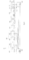
- Figs. 1a-1c are used to describe schematically possible applications of a transmission apparatus 10, or transmitter, for transmitting data signals according to the present invention, in which it can be associated with electric networks 11 of the distribution or industrial type ( fig. 1a ), the domestic type ( fig. 1b ), or combined domestic and distribution ( fig. 1c ).
- Each electric network 11 can include electric conductors 11 a through which the electric power signal or network signal is conducted and, for example in the case of distribution or industrial networks, it can include one or more transformer substations 12, 13.
- Fig. 1a is used to describe by way of example two transformer substations, in particular a first substation 12 and a second substation 13 which are connected to each other by the electric conductors 11a of an electric network 11.
- the transmission apparatus 10 is configured to transmit data signals through the electric conductors 11 a to a reception apparatus or receiver 15.
- the receiver 15 can be installed inside the second substation 13, and is configured to extract in a known manner the information contained in the signals transmitted by the transmission apparatus 10 and carried to the second substation 13 by the electric conductors 11a.
- the reciprocal communication between the substations 12 and 13 can allow to remotely execute operations to automate the electric networks 11.
- the transmission apparatus 10 and receiver 15 can be integrated in a single transceiver device able to establish a two-directional communication.
- the transmission apparatus 10 can be integrated inside a domestic appliance 16. It can be connected to the domestic electric network 11 to transmit through the corresponding electric conductors 11 a a data signal relating to the consumption of the domestic appliance 16.
- the data signal can be transmitted for example to a meter 17 or a domotic control unit 18, each provided with a receiver 15.
- Fig. 1c is used to describe another solution, in which it can be provided that each of a plurality of domestic users 19 includes a transmission apparatus 10 integrated inside its electric energy meter 17.
- Each transmission apparatus 10 can be connected to the electric network 11 to transmit, through the corresponding conductors 11 a, the consumption relating to the domestic user 19 to a concentrator 20, which can for example be located in one of the transformer substations 12, 13 of the distribution electric network 11.
- Data signals arriving from transmission apparatuses 10 integrated in respective domestic appliances 16 can be transmitted to the meter 17 of each domestic user 19.
- an example application of the transmission apparatus 10 can be to control, monitor and adjust the lighting devices in an anthropized structure, such as a commercial building, an airport, an industrial building or a home.
- Fig. 2a is used, using functional blocks, to describe forms of embodiment of a method for transmitting data signals, indicated in its entirety by the reference number 21.
- the method 21 provides to generate one or more pulsed data signals 30 starting from a digital information stream 22, in which the pulsed data signals 30 are broadband with respect to the data rate of the same digital information stream 22, and the transmission of the signals through an electric network 11, which functions as a transmission mean.
- the method 21 can provide a processing step 21 a of the digital information stream 22 containing one or more digital data signals comprising one or more symbols, each of which represents a piece of information to be transmitted.
- the data can come for example from instruments, sensors or detection devices, or measurement or control devices of various types.
- the digital information stream 22 can be encoded in a channel pre-coding step, stage or operation 23.
- the channel pre-coding step 23 provides to repeat, by means of known redundancy techniques, the signal or signals contained in the digital information stream 22, to strengthen the communication and obtain a pre-coded digital information stream 22a.
- a possible implementation of the channel pre-coding step 23 is given by the repetition of the symbols of the digital information stream 22, or information symbols, for a determinate number of times.
- the pre-coded digital stream 22a is subsequently processed in a power pre-coding and mapping step or stage or operation 24.
- the power pre-coding and mapping step provides to reduce the ratio between peak value and mean value of the power (PAPR - Peak to Average Power Ratio) of the signal associated to the pre-coded digital stream 22a within a time interval comprised between two successive wave forms or signatures, also known as epoch.
- the reduction in the ratio between maximum and average value, or PAPR can be made by introducing into the pre-coded digital stream 22a wave forms of increasing length but, for example, decreasing amplitude.
- each information symbol of the pre-coded digital stream 22a is encoded in a new sequence of several symbols, to obtain an encoded digital stream 22b.
- sequences of symbols thus obtained can be orthogonal.
- the average power of the signal data that defines the encoded digital stream 22b obtained with the power precoding and mapping 24 is kept low, because it is scaled down, also taking into account a possible period of inactivity or silent period during which no signals are transmitted, but the peak power goes down because it is calculated in correspondence with the maximum, decreasing, of each wave form or signature 31 of the pulsed signal 30.
- the use of the power precoding and mapping 24 and consequent reduction in the ratio between maximum and average values, or PAPR entails a simplification of the physical structure or hardware of the interface or front end of the transmission apparatus 10, and allows to further improve characteristics in terms of coexistence of a plurality of data signals.
- the power precoding and mapping 24 provides to map sequences of bits encoded by the channel pre-coding stage 23 into symbols that for example can belong to a multi-level alphabet.
- the method 21 includes a signal generating step 21b, which provides that the digital information stream 22 is modulated according to a modulation operation or stage 25, during which it is provided that the digital information stream 22 is converted into a pulsed data signal 30 of the analog type.
- the encoded digital stream 22b is modulated to be converted into the pulsed data signal 30 of the analog type.
- the method 21 also provides that the signal generating step 21b includes a filtering operation or stage 26 in which it is provided to adapt the spectrum of the pulsed data signal 30 to the conditions of the transmission mean defined by the electric network 11 with the corresponding electric conductors 11a.
- This adaptation is performed with the purpose, for example, of maximizing the signal to noise ratio (SNR) measured at the receiver 15, given a constraint of power spectral density (PSD) or overall power of the pulsed data signal 30 transmitted.
- SNR signal to noise ratio
- PSD power spectral density
- the adaptation performed in the filtering stage 26 can take into account the frequency response of the channel and the line impedance of the electric network 11.
- the line impedance is the impedance of the electric network 11 calculated at the gate to which the transmission apparatus 10 is connected.
- pulsed data signal 30 we mean a data signal having a trend defined by a succession of pulses, or a succession of groups of pulses.
- the pulsed data signal 30 obtained at the end of the signal generating step 21b is a broadband signal having a band spectrum much larger than the original digital information stream 22. This allows to exploit the difference in frequency so as to offer greater robustness to the pulsed data signal 30 transmitted and containing the information present in the digital information stream 22.
- Fig. 3 is used to describe forms of embodiment of the pulsed data signal 30 in which it is defined by a succession of signatures 31 alternated with periods without signal, also called silent periods 32.
- the pulsed wave forms or signatures 31 can include a single pulse or a plurality of consecutive pulses grouped together, as shown by way of example in fig. 3 .
- the time interval between the beginning of two consecutive signatures 31 is known as epoch 33.
- the pulsed wave forms or signatures 31 are therefore separated by silent periods 32 and are transmitted with periods equal to the epoch 33.
- successive signatures 31 associated with successive symbols of the encode digital stream 22b can vary in the form, so as to guarantee maximum adaptation to the characteristics of the transmission channel, interference and line impedance of the electric network 11 through which they are transmitted.
- the method 21 also includes a coupling and transmission step 21 c that allows to transmit the pulsed data signal 30 in the electric conductors 11a of the electric network 11 toward the receiver 15.
- Decoding may also be provided, by the receiver 15, of the pulsed data signal 30, to find the original digital information stream 22.
- the method 21 can include a step of assessing the line impedance 27 during which a resistive component and a reactive component of the line impedance of the electric network 11 are calculated, in order to calculate the disadaptation of the pulsed data signal 30 generated.
- an assessment of the frequency response of the channel can be provided at the receiver 15.
- the adaptation to the line impedance is obtained partly by means of software, in the modulation 25 and filtering 26 stages, on a programmable platform and partly by means of hardware in the coupling and transmission step 21c, with discrete electronic devices.
- programmable platforms are FPGA (Field Programmable Gate Array) or DSP (Digital Signal Processor).
- the pulsed data signal 30 can be transmitted at frequencies where the disadaptations are minimized.
- it may be provided to remodulate the power transmitted according to a scale factor that takes into account the disadaptations, so that the actual spectrum of the pulsed data signal 30 transmitted coincides exactly with the one desired, and is not significantly different due to the losses of disadaptation and reflection that arise at the point of connection of the transmission apparatus 10 to the electric network 11.
- the pulsed data signal 30 can be designed and hence modulated in the modulation stage 25 as the sum of pulsed wave forms 31 that are similar in form but distanced by a delay ⁇ i , where the subscript indicates the i-th wave form.
- the generic pulsed data signal 30 at output from the modulation stage 25 can be described, in the time domain, by the sum of as many components as there are epochs 33.
- the definition of the pulsed data signal 30 in the domain of continuous time and the corresponding transposition to the frequency domain, through Fourier transform, can allow to design the value of ⁇ to make the frequency intervals in which the pulsed data signal 30 behaves like a notch filter coincide with the frequencies where the transmission channel has greater attenuation or where it is not deemed appropriate to transmit the pulsed data signal 30.
- Fig. 2b is used to describe forms of embodiment of the method 21 in which the power precoding and mapping stage 24 can be followed by a spatial pre-coding step or stage 28.
- the spatial pre-coding stage 28 provides to implement known techniques to exploit the spatial diversity given by the electric network 11 to several inputs and outputs, or multiple-input, multiple-output, or MIMO. In fact, when more than two electric conductors 11a are present, it is possible to instantiate a MIMO communication by transmitting pulsed data signals 30 on different pairs of electric conductors 11a.
- a possible implementation of the spatial pre-coding stage 28 is given by, but is not limited to, so-called "space-time block codes".
- the method 21 can provide that the signal generating step 21b includes a plurality of modulation stages 25, for example equal in number to the number of inputs of the transmission mean, where the inputs are defined by the electric conductors 11 a and the transmission mean is defined by the electric network 11.
- Each modulation stage 25, performed after the spatial pre-coding step 28, provides to convert the encoded digital stream 22b into pulsed data signals 30 provided with signatures 31, followed by silent periods 32 and with a period equal to an epoch 33.
- the amplitude, step, number and position of the pulses of each signature 31, and also the duration of each epoch 33, are designed to maximize the signal noise ratio (SNR) to the receiver 15 on each of the channels that the transmission mean has available, to avoid the bands where the electric network 11 has strong attenuations or where there is strong interference, to minimize the energy and/or power spectrum density (PSD) of the pulsed data signals 30 transmitted, and possibly to prevent the transmission of said signals in prohibited bands.
- SNR signal noise ratio
- the pulsed data signals 30 may be provided to design the pulsed data signals 30 to contain the corresponding average PSD within a spectrum from a few MHz to a few dozen MHz or in other portions of the frequency spectrum.
- the modulation stage or stages 25 are implemented on a digital signal processing platform (FPGA or DSP).
- FPGA digital signal processing platform
- one or more modulation stages 25 can exploit known techniques to generate broadband signals with low peak power, such as for example radar pulse compression techniques.
- Each component of the pulsed data signal 30 is a function of the output from the spatial precoding stage 28 to the n-th epoch, the amplitude of the signature 31 to the n-th epoch 33, which allows to modulate the amplitude.
- Each component also depends on the duration of the epoch 33, on the instant in time, and on the trend of the pulsed wave form, taking into account the temporal shift or offset with which the signature 31 is transmitted in the n-th epoch 33, which allows to modulate the position.
- the amplitude modulation is not adaptive, that is, it does not vary as the characteristics of the channel vary, while the offset is equal to zero.
- the modulation can be of the amplitude, position or a combination of them both, and can be adaptive, both in the order of modulation and in the number of levels of amplitude and in the number of offsets, and in the form of the pulse.
- the pulse coincides with the pulse response of a band-pass filter with band B, and is flat in pass band.
- Fig. 4 is used to describe forms of embodiment of a transmission apparatus 10 for the transmission of pulsed data signals 30 in which it includes an electronic pulsed signal generation device 201 configured to generate the pulsed data signals 30 as pulsed analog data signals defined by an alternate succession of pulsed wave forms, or signatures 31 and periods without a signal or silent periods 32.
- an electronic pulsed signal generation device 201 configured to generate the pulsed data signals 30 as pulsed analog data signals defined by an alternate succession of pulsed wave forms, or signatures 31 and periods without a signal or silent periods 32.
- the electronic generation device 201 can include, as basic physical components or hardware, an electric accumulation element 101, a first load switch 103 and a second discharge switch 104, both connected to the electric accumulation element 101.
- the electric accumulation element 101 can be a capacitor or inductor or other passive element, or a battery of capacitors, inductors or other passive elements.
- the transmission apparatus 10 can also include an electric feed device 102 at input, to which the first load switch 103 is connected.
- the electric accumulation element 101 can be interposed between the two switches 103 and 104, to which it is connected.
- the discharge switch 104 can also be connected to a sign switch 105.
- the transmission apparatus 10 can include a control unit 106.
- control unit 106 can be configured to carry out at least the processing step 21a, before the generation of the one or more data signals 30 by means of the electronic generation device 201, which comprises:
- control unit 106 can be connected at least to the load and discharge switches 103, 104 and configured to control and command the functioning thereof (see fig. 4 ).
- the load switch 103 is activated during the silent period 32, while the discharge switch 104 is activated in the instants complementary to the epoch 33 with respect to the silent period 32, that is, during the execution of the corresponding signature 31.
- the two switches 103, 104 are never active at the same time.
- control unit 106 can be connected to the sign switch 105, to control the functioning thereof (see fig. 4 ).
- the electronic generation device 201 instead of being defined by the load switch 103, the discharge switch 104 and the electric accumulation element 101, can consist of electronic components configured for the implementation on a digital platform of the generation of pulsed signals and for the functional emulation via software of said hardware components.
- the electronic generation device 201 can allow to generate signatures 31 adapted to the frequency response of the transmission channel and the line impedance at input to the electric network 11. This can be intended, for example, to maximize the signal noise ratio to the receiver 15.
- the assessment of the frequency response is obtained at the receiver 15.
- an assessment module of the line impedance 107 is provided, configured to effect an assessment of the line impedance 27.
- the assessment module of the line impedance 107 is configured to calculate a resistive component and a reactive component of the corresponding line impedance.
- the assessment module of the line impedance 107 can be connected to the electric network 11.
- the assessment module of the line impedance 107 can also be connected to the control unit 106, to transmit to it the necessary information (see fig. 4 ).
- the control unit 106 can be configured to process the information relating to the frequency response of the channel and the line impedance thus calculated and/or assessed.
- the transmission apparatus 10 includes a filtering device 108 connected downstream of the sign switch 105.
- the filtering device 108 can be provided to adapt the pulsed analog signals to the conditions of the transmission mean defined by the electric network 11.
- the filtering device 108 can be a low pass or pass band filter made using only passive elements, or it can be an adaptive filter and can be designed and configured as a function of the line impedance or frequency response of the channel to occupy suitable spectral portions and to allocate there the available power.
- the filtering device 108 can be configured to adapt the pulsed data signals 30 to select suitable spectral portions occupied by the pulsed data signals 30.
- the control unit 106 can be connected to the filtering device 108, to control its functioning.
- the transmission apparatus 10 can comprise an adaptive coupler 110 connected between the filtering device 108 and the electric network 11.
- the transmission apparatus 10 is therefore connected to the electric network 11 through the adaptive coupler 110, which receives from the filtering device 108 the pulsed data signals 30 and injects them into the electric network 11 through the electric conductors 11a.
- the control unit 106 can also be connected to the adaptive coupler 110, to control its functioning.
- the adaptive coupler 110 can include an electronic coupling circuit 109 that connects, at output, the transmission apparatus 10 to the electric conductors 11a cited above.
- the coupling circuit 109 can be the adaptive type and configured to perform a physical or hardware adaptation, using discrete electronic components, of the pulsed data signals 30 to the line impedance of the electric network 11 on the band of the pulsed data signals 30, and hence allows to implement at least part of the filtering stage 26 described above. Furthermore, the coupling circuit 109 is configured to superimpose the pulsed data signals 30 generated by method 21 over the network signal carried by the electric conductors 11 a. It can also be provided that the coupling circuit 109 is configured to block the propagation of the pulsed data signal 30 to the filtering device 108.
- the coupling circuit 109 can include a transformer, including a center tapped transformer, capacitors, varistors and other passive protection elements.
- the coupling circuit 109 is always made with discrete electronic components, active or passive, in some forms of embodiment of the transmission apparatus 10 it may be provided that the electronic circuitry comprising the load switch 103, the discharge switch 104, the sign switch 105, the assessment module of the line impedance 107 and the filtering device 108, is partly or completely implemented on a digital platform and then, in practice, emulated by means of suitable computer programs and algorithms, that is, software.
- Some forms of embodiment can provide the execution of various steps, passages and operations, as described above.
- the steps, passages and operations can be done at least partly with instructions performed by a machine which cause the execution of certain steps by a general-purpose or special-purpose processor.
- these steps, passages and operations can be performed by specific hardware components that contain hardware logic to perform the steps, or by any combination of components for programmed computers and personalized hardware components.
- a machine-readable or computer-readable program can determine which tasks can be done in accordance with the method according to the present description.
- the program is a machine-readable or computer-readable software.
- the machine or computer includes a code to generate and memorize information and data introduced or generated during the course of the method according to the present description.
- Forms of embodiment of the method in accordance with the present description can be included in a program for computers that can be memorized in a computer-readable mean that includes the instructions that, once performed by the transmission apparatus 10, determine the execution of the method discussed here.
- elements according to the present invention can be given as machine-readable means to memorize the instructions which can be carried out by the machine.
- the machine-readable means can include, without being limited to, floppy disks, optical disks, CD-ROM, optical-magnetic disks, ROM, RAM, EPROM, EEPROM, optical or magnetic cards, propagation means or other types of machine-readable means suitable to memorize electronic information.
- at least parts of the present invention can be downloaded as a computer program that can be transferred from a remote computer (for example a server) to a requesting computer (for example a client), by means of data signals received with carrier waves or other propagation means, via a communication connection (for example a modem or a network connection).
Landscapes
- Engineering & Computer Science (AREA)
- Computer Networks & Wireless Communication (AREA)
- Signal Processing (AREA)
- Power Engineering (AREA)
- Cable Transmission Systems, Equalization Of Radio And Reduction Of Echo (AREA)
Applications Claiming Priority (1)
| Application Number | Priority Date | Filing Date | Title |
|---|---|---|---|
| ITUD20140088 | 2014-05-23 |
Publications (1)
| Publication Number | Publication Date |
|---|---|
| EP2947784A1 true EP2947784A1 (fr) | 2015-11-25 |
Family
ID=51230102
Family Applications (1)
| Application Number | Title | Priority Date | Filing Date |
|---|---|---|---|
| EP15161524.2A Withdrawn EP2947784A1 (fr) | 2014-05-23 | 2015-03-27 | Appareil et procédé pour la transmission de signaux de données |
Country Status (1)
| Country | Link |
|---|---|
| EP (1) | EP2947784A1 (fr) |
Cited By (2)
| Publication number | Priority date | Publication date | Assignee | Title |
|---|---|---|---|---|
| US20230126483A1 (en) * | 2021-10-27 | 2023-04-27 | Cisco Technology, Inc. | Systems and methods for reducing false radar detection |
| CN116684041A (zh) * | 2023-06-20 | 2023-09-01 | 深圳讯道实业股份有限公司 | 基于5g通讯线缆的数据传输方法及该线缆 |
Citations (7)
| Publication number | Priority date | Publication date | Assignee | Title |
|---|---|---|---|---|
| WO2003030397A1 (fr) | 2001-09-28 | 2003-04-10 | Siemens Aktiengesellschaft | Procede de reduction du rayonnement de signaux injectes dans des lignes d'alimentation en energie |
| GB2383724A (en) | 2001-12-15 | 2003-07-02 | Univ Lancaster | Space time coded data transmission via inductive effect between adjacent power lines |
| US20040022304A1 (en) | 2002-06-21 | 2004-02-05 | John Santhoff | Ultra-wideband communication though local power lines |
| WO2004021658A1 (fr) | 2000-12-14 | 2004-03-11 | Pulse-Link, Inc. | Codage et decodage d'informations en ultra-large bande |
| GB2393370A (en) | 2002-10-02 | 2004-03-24 | Artimi Ltd | Microwave frequency communication over cabling |
| US20040218688A1 (en) | 2002-06-21 | 2004-11-04 | John Santhoff | Ultra-wideband communication through a power grid |
| US20100296550A1 (en) | 2008-01-31 | 2010-11-25 | Commissar. A L'energ. Atom. Et Aux Energ. Altern. | Method of space time coding with low papr for multiple antenna communication system of the uwb pulse type |
-
2015
- 2015-03-27 EP EP15161524.2A patent/EP2947784A1/fr not_active Withdrawn
Patent Citations (7)
| Publication number | Priority date | Publication date | Assignee | Title |
|---|---|---|---|---|
| WO2004021658A1 (fr) | 2000-12-14 | 2004-03-11 | Pulse-Link, Inc. | Codage et decodage d'informations en ultra-large bande |
| WO2003030397A1 (fr) | 2001-09-28 | 2003-04-10 | Siemens Aktiengesellschaft | Procede de reduction du rayonnement de signaux injectes dans des lignes d'alimentation en energie |
| GB2383724A (en) | 2001-12-15 | 2003-07-02 | Univ Lancaster | Space time coded data transmission via inductive effect between adjacent power lines |
| US20040022304A1 (en) | 2002-06-21 | 2004-02-05 | John Santhoff | Ultra-wideband communication though local power lines |
| US20040218688A1 (en) | 2002-06-21 | 2004-11-04 | John Santhoff | Ultra-wideband communication through a power grid |
| GB2393370A (en) | 2002-10-02 | 2004-03-24 | Artimi Ltd | Microwave frequency communication over cabling |
| US20100296550A1 (en) | 2008-01-31 | 2010-11-25 | Commissar. A L'energ. Atom. Et Aux Energ. Altern. | Method of space time coding with low papr for multiple antenna communication system of the uwb pulse type |
Cited By (4)
| Publication number | Priority date | Publication date | Assignee | Title |
|---|---|---|---|---|
| US20230126483A1 (en) * | 2021-10-27 | 2023-04-27 | Cisco Technology, Inc. | Systems and methods for reducing false radar detection |
| US11910423B2 (en) * | 2021-10-27 | 2024-02-20 | Cisco Technology, Inc. | Systems and methods for reducing false radar detection |
| CN116684041A (zh) * | 2023-06-20 | 2023-09-01 | 深圳讯道实业股份有限公司 | 基于5g通讯线缆的数据传输方法及该线缆 |
| CN116684041B (zh) * | 2023-06-20 | 2024-02-06 | 深圳讯道实业股份有限公司 | 基于5g通讯线缆的数据传输方法及该线缆 |
Similar Documents
| Publication | Publication Date | Title |
|---|---|---|
| US8306090B2 (en) | Power line communication using frequency hopping | |
| Korki et al. | Performance evaluation of a narrowband power line communication for smart grid with noise reduction technique | |
| CN102355313B (zh) | 基于信道认知技术的电力线通信方法 | |
| Ndjiongue et al. | Power line communications (PLC) technology: More than 20 years of intense research | |
| Razazian et al. | G3-PLC field trials in US distribution grid: Initial results and requirements | |
| CN102437867B (zh) | 基于信道认知技术的电力线通信设备 | |
| CN101159449A (zh) | 低压配电网载波通信系统中的一种通信方法 | |
| CN104954311B (zh) | 基于ofdm调制的电力线载波通信系统前导信号生成方法 | |
| Aderibole et al. | Power line communication for low-bandwidth control and sensing | |
| EP2947784A1 (fr) | Appareil et procédé pour la transmission de signaux de données | |
| CN102025398B (zh) | 有线载波通信方法与装置 | |
| Ma et al. | Matlab based simulation of the efficiency of the complex ofdm on power line communication technology | |
| Kim et al. | Channel measurements and field tests of narrowband power line communication over Korean underground LV power lines | |
| CN202309702U (zh) | 基于信道认知技术的电力线通信设备 | |
| CN103326981B (zh) | 一种基于ofdm的电力线载波通信的控制信号调制方法 | |
| Poluektov et al. | Designing a power-line-communication-based LoM protection concept with application of software-defined radios | |
| de MBA Dib et al. | A discussion about hybrid PLC-wireless communication for smart grids | |
| Mishra et al. | A channel model for power line communication using 4PSK technology for diagnosis: Some lessons learned | |
| Bali et al. | S-FSK modem design and experimental validation for robust narrowband powerline communication | |
| Tiru et al. | Multipath effects and adaptive transmission in presence of indoor power line background noise | |
| Poluektov et al. | Sensitivity analysis of a PLC-based anti-islanding solution using DSSS | |
| Jagannathan et al. | Performance of OFDM-based power line communication under asynchronous noise | |
| Chandralekha et al. | A Survey on Narrow Band Power Line Carrier Communication for Efficient and Secure Data Transmission in Smart Grid Applications | |
| RU2491719C1 (ru) | Способ и устройство передачи и приема информации по электросетям | |
| Cortés-Arrabal | Modulation and multiple access techniques for indoor broadband power-line communications |
Legal Events
| Date | Code | Title | Description |
|---|---|---|---|
| PUAI | Public reference made under article 153(3) epc to a published international application that has entered the european phase |
Free format text: ORIGINAL CODE: 0009012 |
|
| AK | Designated contracting states |
Kind code of ref document: A1 Designated state(s): AL AT BE BG CH CY CZ DE DK EE ES FI FR GB GR HR HU IE IS IT LI LT LU LV MC MK MT NL NO PL PT RO RS SE SI SK SM TR |
|
| AX | Request for extension of the european patent |
Extension state: BA ME |
|
| STAA | Information on the status of an ep patent application or granted ep patent |
Free format text: STATUS: THE APPLICATION IS DEEMED TO BE WITHDRAWN |
|
| 18D | Application deemed to be withdrawn |
Effective date: 20160526 |