EP2947661A1 - Barrette de montage d'un panneau par serrage sur un cadre porteur - Google Patents
Barrette de montage d'un panneau par serrage sur un cadre porteur Download PDFInfo
- Publication number
- EP2947661A1 EP2947661A1 EP15167894.3A EP15167894A EP2947661A1 EP 2947661 A1 EP2947661 A1 EP 2947661A1 EP 15167894 A EP15167894 A EP 15167894A EP 2947661 A1 EP2947661 A1 EP 2947661A1
- Authority
- EP
- European Patent Office
- Prior art keywords
- clamping
- bar
- panel
- screws
- edge
- Prior art date
- Legal status (The legal status is an assumption and is not a legal conclusion. Google has not performed a legal analysis and makes no representation as to the accuracy of the status listed.)
- Granted
Links
Images


Classifications
-
- F—MECHANICAL ENGINEERING; LIGHTING; HEATING; WEAPONS; BLASTING
- F16—ENGINEERING ELEMENTS AND UNITS; GENERAL MEASURES FOR PRODUCING AND MAINTAINING EFFECTIVE FUNCTIONING OF MACHINES OR INSTALLATIONS; THERMAL INSULATION IN GENERAL
- F16B—DEVICES FOR FASTENING OR SECURING CONSTRUCTIONAL ELEMENTS OR MACHINE PARTS TOGETHER, e.g. NAILS, BOLTS, CIRCLIPS, CLAMPS, CLIPS OR WEDGES; JOINTS OR JOINTING
- F16B5/00—Joining sheets or plates, e.g. panels, to one another or to strips or bars parallel to them
- F16B5/06—Joining sheets or plates, e.g. panels, to one another or to strips or bars parallel to them by means of clamps or clips
- F16B5/0607—Joining sheets or plates, e.g. panels, to one another or to strips or bars parallel to them by means of clamps or clips joining sheets or plates to each other
- F16B5/0614—Joining sheets or plates, e.g. panels, to one another or to strips or bars parallel to them by means of clamps or clips joining sheets or plates to each other in angled relationship
-
- F—MECHANICAL ENGINEERING; LIGHTING; HEATING; WEAPONS; BLASTING
- F16—ENGINEERING ELEMENTS AND UNITS; GENERAL MEASURES FOR PRODUCING AND MAINTAINING EFFECTIVE FUNCTIONING OF MACHINES OR INSTALLATIONS; THERMAL INSULATION IN GENERAL
- F16B—DEVICES FOR FASTENING OR SECURING CONSTRUCTIONAL ELEMENTS OR MACHINE PARTS TOGETHER, e.g. NAILS, BOLTS, CIRCLIPS, CLAMPS, CLIPS OR WEDGES; JOINTS OR JOINTING
- F16B2/00—Friction-grip releasable fastenings
- F16B2/02—Clamps, i.e. with gripping action effected by positive means other than the inherent resistance to deformation of the material of the fastening
- F16B2/06—Clamps, i.e. with gripping action effected by positive means other than the inherent resistance to deformation of the material of the fastening external, i.e. with contracting action
- F16B2/065—Clamps, i.e. with gripping action effected by positive means other than the inherent resistance to deformation of the material of the fastening external, i.e. with contracting action using screw-thread elements
-
- G—PHYSICS
- G21—NUCLEAR PHYSICS; NUCLEAR ENGINEERING
- G21F—PROTECTION AGAINST X-RADIATION, GAMMA RADIATION, CORPUSCULAR RADIATION OR PARTICLE BOMBARDMENT; TREATING RADIOACTIVELY CONTAMINATED MATERIAL; DECONTAMINATION ARRANGEMENTS THEREFOR
- G21F7/00—Shielded cells or rooms
- G21F7/04—Shielded glove-boxes
-
- F—MECHANICAL ENGINEERING; LIGHTING; HEATING; WEAPONS; BLASTING
- F16—ENGINEERING ELEMENTS AND UNITS; GENERAL MEASURES FOR PRODUCING AND MAINTAINING EFFECTIVE FUNCTIONING OF MACHINES OR INSTALLATIONS; THERMAL INSULATION IN GENERAL
- F16B—DEVICES FOR FASTENING OR SECURING CONSTRUCTIONAL ELEMENTS OR MACHINE PARTS TOGETHER, e.g. NAILS, BOLTS, CIRCLIPS, CLAMPS, CLIPS OR WEDGES; JOINTS OR JOINTING
- F16B5/00—Joining sheets or plates, e.g. panels, to one another or to strips or bars parallel to them
- F16B5/06—Joining sheets or plates, e.g. panels, to one another or to strips or bars parallel to them by means of clamps or clips
- F16B5/0607—Joining sheets or plates, e.g. panels, to one another or to strips or bars parallel to them by means of clamps or clips joining sheets or plates to each other
- F16B5/0621—Joining sheets or plates, e.g. panels, to one another or to strips or bars parallel to them by means of clamps or clips joining sheets or plates to each other in parallel relationship
- F16B5/0635—Joining sheets or plates, e.g. panels, to one another or to strips or bars parallel to them by means of clamps or clips joining sheets or plates to each other in parallel relationship fastened over the edges of the sheets or plates
-
- Y—GENERAL TAGGING OF NEW TECHNOLOGICAL DEVELOPMENTS; GENERAL TAGGING OF CROSS-SECTIONAL TECHNOLOGIES SPANNING OVER SEVERAL SECTIONS OF THE IPC; TECHNICAL SUBJECTS COVERED BY FORMER USPC CROSS-REFERENCE ART COLLECTIONS [XRACs] AND DIGESTS
- Y10—TECHNICAL SUBJECTS COVERED BY FORMER USPC
- Y10T—TECHNICAL SUBJECTS COVERED BY FORMER US CLASSIFICATION
- Y10T403/00—Joints and connections
- Y10T403/70—Interfitted members
- Y10T403/7062—Clamped members
-
- Y—GENERAL TAGGING OF NEW TECHNOLOGICAL DEVELOPMENTS; GENERAL TAGGING OF CROSS-SECTIONAL TECHNOLOGIES SPANNING OVER SEVERAL SECTIONS OF THE IPC; TECHNICAL SUBJECTS COVERED BY FORMER USPC CROSS-REFERENCE ART COLLECTIONS [XRACs] AND DIGESTS
- Y10—TECHNICAL SUBJECTS COVERED BY FORMER USPC
- Y10T—TECHNICAL SUBJECTS COVERED BY FORMER US CLASSIFICATION
- Y10T403/00—Joints and connections
- Y10T403/70—Interfitted members
- Y10T403/7062—Clamped members
- Y10T403/7064—Clamped members by wedge or cam
- Y10T403/7066—Clamped members by wedge or cam having actuator
- Y10T403/7067—Threaded actuator
Definitions
- the invention relates to the assembly of a closed enclosure, such as a glove box for handling radioactive material, this enclosure comprising a structure carrying a flat panel which is applied to a frame of this structure and clamped on this frame by clamping means.
- a chamber 1 of the glove box type for handling radioactive material is formed of a rigid support structure 2 consisting of profiles arranged along the edges of a parallelepiped, on which are reported panels 3, which can be transparent. The panels are fixed to the supporting structure by clamps marked by 4.
- Each profile 6 has a cross section corresponding to the shape of the Omega letter: this section comprises an open concave main portion 7 oriented towards the outside of the enclosure, and which is terminated by two wings 8 and 9 which move away from each other. one of the other.
- the concave main portion 7 extends about three quarters of a turn around the axis of the profile 6. It has a global square shape comprising four consecutive sides 11, 12, 13 and 14 but without one of its vertices at its opening in the opposite direction to the enclosure.
- the sides 12 and 13 correspond to the bottom of the profile, while the sides 11 and 14 correspond to those which are the outermost with respect to the enclosure, and against which closure panels of the enclosure , identified by 16 and 17.
- the wing 8 extends the side 11 extending perpendicularly to this side 11 and in the opposite direction to the central region of the enclosure.
- the wing 9 extends the side 14 extending perpendicularly to this side in a direction opposite to the central region of the enclosure.
- the two wings 8 and 9 thus extend at right angles to each other, and jointly define an opening of the profile flaring outwardly.
- the panel 16 has its inner face 18 applied along its edge on the side 11 of the profile 6, via a seal 19 interposed between this panel 16 and the side 11.
- the edge 21 of this panel 16 is opposite the flange 8 of the profile 6, and the panel 16 is held pressed against the side 11 by a clamp 4.
- the clamp 4 has a fixed key 23 which is engaged in the concavity of the profile to bear on the inner face of the side 11, and a movable key 24 which is supported on the outer face 26 of the panel 16, via a clamping sleeve 27 called counter-frame. This counter frame evenly distributes the punctual clamping force of the various clamps, to limit the stresses in the panel which can be fragile when made of polymethacrylate.
- the clamps 4 are thus distributed around the entire periphery of the panel 16 to press tightly against the supporting structure, also called carcass, that jointly form the profiles assembled to each other.
- the number of clamps is important to ensure proper sealing, so that the mounting of such a glove box is necessarily long and tedious.
- the tightening of the first clamps while maintaining a counter frame tends to move the counter frame or to make it fall.
- the spacing between the clamps is determined by the operator so that it can be too random and fluctuate from one operator to another. Tightening a clamp tends to loosen the adjacent clamps, or even to move them.
- the threads of the clamping screw of each clamp are portions that may be difficult to decontaminate in case of contamination external to the box.
- the series of clamps that equip a glove box protrude, so that they hang clothes and / or combination of operators.
- the object of the invention is to propose a solution to overcome these disadvantages.
- the invention relates to a bar for mounting a panel by clamping the periphery of this panel on a profile of a supporting structure to form a closed enclosure, this bar comprising a body including a base extended by two flanks jointly defining a rectilinear channel for overlapping a panel edge and a profile edge to grip them, one of the flanks comprising a plurality of tapped holes, each tapped hole being provided with a clamping screw.
- This bar and has an elongated shape for easy gripping, and it carries several clamping screws regularly spaced, which significantly simplifies the mounting of a panel.
- the invention also relates to a bar thus defined, further comprising a bearing pad of the same length as the body and along the side which carries each clamping screw, at least one clamping screw being secured to the support pad while being free to turn relative to this support pad.
- the invention also relates to a bar thus defined, comprising two clamping screws secured to the support pad while each being free to rotate relative to this buffer, these two screws being the two screws closest to the ends of the body.
- the invention also relates to a bar thus defined, comprising a protective tab extending the side carrying the clamping screws to cover the space separating the sidewall of the panel when the bar is in place.
- the invention also relates to a bar thus defined, wherein the tongue is an insert fixed by interlocking and / or bonding on the outer face of the flank carrying the clamping screws.
- the invention also relates to a bar thus defined, wherein the insert member carrying the tongue is fitted into the tapped holes of the side which carries it.
- the idea underlying the invention is to replace the sets of spot clamps of the state of the art, by linear bars each comprising a linear body carrying several clamping screws and a counterframe element mounted in a captive way.
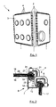
- FIG. 3 there is shown a section 28 of enclosure structure carrying a side panel 29 which is mounted on this structure by means of a bar according to the invention identified by 31.
- the profile 28 has a support side 32 of an inner face 33 of the panel 29, and which is extended by a flange 34 extending perpendicularly to this side.
- the panel 29 is applied against the support side 32 via a seal 36, being positioned so that the edge of this panel 29 is vis-à-vis and at a short distance from the wing 34.
- the bar 31 has a main body 37, visible in the figure 4 , approaching a profile having in cross section the shape of the letter C, and which is intended to overlap the edge of a panel 29 and the corresponding side of a profile to enclose.
- This main body 37 which is for example made of aluminum, thus delimits an internal channel 38 extending in the main direction of this body, denoted AX. It comprises two edges 39 and 41 each corresponding to a branch of the C section of this body and which are joined by a central base 42.
- the edge 41 of this main body here comprises four tapped holes 44 parallel to each other and perpendicular to the direction AX, and each opening into the channel 38 at the inner face of the edge 41.
- Each tapped hole is intended to receive a clamping screw such as the screw 46 Figures 3 and 5 , which is a so-called headless screw, the screw end has a footprint.
- This footprint is for example a hexagon socket imprint allowing the engagement of a key or a suitable tool for clamping.
- the edge 41 carrying the clamping screws has a sufficient thickness so that these screws, which are also provided relatively short, do not exceed the outer face of the edge 41 when they are in place.
- each screw 46 thus protrudes into the channel 38 of the inner face of the edge 41 so as to be opposite the opposite edge, namely the edge 39.
- the bar according to the invention also comprises a frame member, marked by 47, and which is secured to the rest of the bar to be captive so as to simplify the mounting operations of the box.
- two of the four screws 46 have tip-like or nipple-shaped clamping ends, and these ends are engaged and each crimped into a corresponding hole in the counter frame member.
- These two screws 46 which are here the screws located at the end of the body 37 are thus secured to the element of counterframe to make it captive, while being free to rotate with respect to this element.
- the other two screws 46 namely here the two central screws, can in turn be mounted normally.
- the counter-frame element 47 constitutes a bearing pad formed by a strip or plate with a rectangular contour whose length corresponds to the length of the barrette body, and whose width corresponds to the depth of the strip. the channel 38.
- the counter frame element 47 is captive relative to the rest of the bar, and it ensures the homogeneous distribution function of the clamping forces of the various screws 46 when the assembly is in place.
- a protective skirt in the form of a flexible tab flap which is marked by 48, extends the edge 41 of the barrel body 37 extending approximately parallel to the bottom of the channel 38.
- This flap can be manufactured metal or plastic.
- the flexible tongue 48 When the whole is in place, as visible on the Figures 3 and 5 , the flexible tongue 48 has its free edge resting on the outer face of the panel, so that it substantially covers the region of the bar comprising the threads of the screws 46, and which is located between the counter element -frame and the edge 41 of the barrette body.
- This tongue can be attached to the barrel body being attached to the outer face of its edge or flank 41 possibly being attached to the holes having the clamping screws.
- Each bar may be pre-equipped with a protective tab of the same length as the barrette body. But we can also provide to bring a same tongue on a set of bars in place to promote better protection against contamination, free of gaps.
- Each tongue may be in the form of a protective cover engaging and disconnecting without tools on the side of the barrel body and in the threaded holes of its screws, reversibly.
- the bar according to the invention makes it possible to grip a profile side 32 provided with a gasket 36 and a panel 29 to fix them to one another by compressing them between the frame element 47 pressed by the tight screws 46 and the edge or flank 39 of the barrette body.
- the mounting of the bar is significantly simplified since an operator can hold the bar body in one hand and the other hand tighten the screws. the bar in question. Moreover, the absence of relief and roughness of these bars facilitates their handling and cleaning.
- the bars 31 are mounted next to each other along the edge of the frame to tighten this frame all around its periphery to ensure proper sealing.
- the invention applies to closed enclosures consisting of a structure carrying tight panels on this structure, such enclosures existing in a hospital environment in incubators.
- Such enclosures may also correspond to spaces dedicated to the isolation of chemical and bacteriological agents in the medical or pharmaceutical field. They may also be fast-moving mobile speakers in theaters of civilian or military operations.
Landscapes
- Engineering & Computer Science (AREA)
- General Engineering & Computer Science (AREA)
- Mechanical Engineering (AREA)
- Physics & Mathematics (AREA)
- High Energy & Nuclear Physics (AREA)
- Clamps And Clips (AREA)
- Manipulator (AREA)
Abstract
Description
- L'invention concerne l'assemblage d'une enceinte fermée, telle qu'une boîte à gants pour la manipulation de matière radioactive, cette enceinte comprenant une structure portant un panneau plan qui est appliqué sur un cadre de cette structure et serré sur ce cadre par des moyens de serrage.
- Comme visible sur la
figure 1 , une enceinte 1 de type boîte à gants pour la manipulation de matière radioactive, est formée d'une structure porteuse rigide 2 constituée de profilés agencés selon les arêtes d'un parallélépipède, sur laquelle sont rapportés des panneaux 3, pouvant être transparents. Les panneaux sont fixés à la structure porteuse par des serre-joints repérés par 4. - La fixation des panneaux, qui est représentée de manière plus détaillée dans la vue en coupe de la
figure 2 est assurée grâce à la coopération des serre-joints 4 avec la section particulière, dite en Omega, des profilés 6 constitutifs de la structure porteuse. - Chaque profilé 6 présente une section transversale correspondant à la forme de la lettre Oméga : cette section comprend une portion principale 7 concave ouverte orientée vers l'extérieur de l'enceinte, et qui est terminée par deux ailes 8 et 9 qui s'éloignent l'une de l'autre.
- La portion principale concave 7 s'étend sur environ trois quarts de tour autour de l'axe du profilé 6. Elle a une forme globale de carré comprenant quatre côtés consécutifs 11, 12, 13 et 14 mais dépourvu de l'un de ses sommets au niveau de son ouverture en direction opposée à l'enceinte. Les côtés 12 et 13 correspondent au fond du profilé, alors que les côtés 11 et 14 correspondent à ceux qui sont le plus à l'extérieur par rapport à l'enceinte, et contre lesquels s'appliquent des panneaux de fermeture de l'enceinte, repérés par 16 et 17.
- L'aile 8 prolonge le côté 11 en s'étendant perpendiculairement à ce côté 11 et en direction opposée à la région centrale de l'enceinte. De manière analogue, l'aile 9 prolonge le côté 14 en s'étendant perpendiculairement à ce côté en direction opposée à la région centrale de l'enceinte. Les deux ailes 8 et 9 s'étendent ainsi à angle droit l'une par rapport à l'autre, et délimitent conjointement une ouverture du profilé s'évasant vers l'extérieur.
- Comme visible dans la
figure 2 , le panneau 16 a sa face interne 18 appliquée, le long de son bord, sur le côté 11 du profilé 6, par l'intermédiaire d'un joint d'étanchéité 19 interposé entre ce panneau 16 et le côté 11. - La tranche 21 de ce panneau 16 est en vis-à-vis de l'aile 8 du profilé 6, et le panneau 16 est maintenu pressé contre le côté 11 par un serre-joint 4. Le serre-joint 4 présente une touche fixe 23 qui est engagée dans la concavité du profilé pour être en appui sur la face interne du côté 11, et une touche mobile 24 qui est en appui sur la face externe 26 du panneau 16, par l'intermédiaire d'une garniture de serrage 27 appelée contre-cadre. Ce contre cadre répartit uniformément l'effort de serrage ponctuel des différents serre joints, pour limiter les contraintes dans le panneau qui peut être fragile lorsque fabriqué en polyméthacrylate.
- Les serre-joints 4 sont ainsi répartis sur tout le pourtour du panneau 16 pour le presser de manière étanche contre la structure porteuse, encore appelée carcasse, que forment conjointement les profilés assemblés les uns aux autres.
- En pratique, le nombre de serre-joints est important pour assurer une étanchéité correcte, de sorte que le montage d'une telle boîte à gants est nécessairement long et fastidieux. Le serrage des premiers serre-joints en maintenant un contre-cadre tend à faire bouger le contre-cadre voire à le faire tomber. Par ailleurs, l'écartement entre les serre-joints est déterminé par l'opérateur de sorte qu'il peut être trop aléatoire et fluctuer d'un opérateur à un autre. Le resserrage d'un serre-joint tend à desserrer les serre-joints adjacents, voire à les faire bouger. En outre, les filets de la vis de serrage de chaque serre-joint constituent des portions qui peuvent être difficiles à décontaminer en cas de contamination externe à la boîte. Enfin, les séries de serre-joints qui équipent une boîte à gants dépassent, de sorte qu'ils accrochent les vêtements et/ou la combinaison des opérateurs.
- Le but de l'invention est de proposer une solution pour remédier à ces inconvénients.
- A cet effet, l'invention a pour objet une barrette de montage d'un panneau par serrage du pourtour de ce panneau sur un profilé d'une structure porteuse pour constituer une enceinte fermée, cette barrette comprenant un corps incluant une base prolongée par deux flancs délimitant conjointement une rigole rectiligne destinée à chevaucher un bord de panneau et un bord de profilé pour les enserrer, l'un des flancs comprenant plusieurs trous taraudés, chaque trou taraudé étant équipé d'une vis de serrage.
- Cette barrette a ainsi une forme allongée facilitant sa préhension, et elle porte plusieurs vis de serrage régulièrement espacées, ce qui simplifie significativement le montage d'un panneau.
- L'invention concerne également une barrette ainsi définie, comprenant en outre un tampon d'appui de même longueur que le corps et longeant le flanc qui porte chaque vis de serrage, au moins une vis de serrage étant solidarisée au tampon d'appui tout en étant libre de tourner par rapport à ce tampon d'appui.
- L'invention concerne également une barrette ainsi définie, comprenant deux vis de serrage solidarisées au tampon d'appui tout en étant chacune libre de tourner par rapport à ce tampon, ces deux vis étant les deux vis les plus proches des extrémités du corps.
- L'invention concerne également une barrette ainsi définie, comprenant une languette protectrice prolongeant le flanc portant les vis de serrage pour couvrir l'espace séparant ce flanc du panneau lorsque la barrette est en place.
- L'invention concerne également une barrette ainsi définie, dans laquelle la languette est un élément rapporté fixé par emboîtement et/ou collage en face externe du flanc portant les vis de serrage.
- L'invention concerne également une barrette ainsi définie, dans laquelle l'élément rapporté portant la languette est emboîté dans les trous taraudés du flanc qui le porte.
-
- La
figure 1 est une vue en perspective d'une boîte à gants de l'Etat de la technique ; - La
figure 2 est une vue en coupe d'un profilé de structure de boîte à gants auquel sont fixés deux panneaux par des serre-joints conformément à l'Etat de la technique ; - La
figure 3 est une vue en perspective d'un corps de barrette de serrage selon l'invention ; - La
figure 4 est une vue en coupe transversale d'une barrette de serrage selon l'invention qui enserre un profilé et un panneau ; - La
figure 5 est une vue en coupe transversale d'une barrette de serrage selon l'invention qui enserre un profilé et un panneau ; - La
figure 6 est une vue partielle d'un panneau monté sur une structure au moyen de barrettes de serrage selon l'invention. - L'idée à la base de l'invention est de remplacer les séries de serre-joints ponctuels de l'Etat de la technique, par des barrettes linéaires comprenant chacune un corps linéaire portant plusieurs vis de serrage et un élément de contre-cadre monté de manière imperdable.
- Dans la
figure 3 , on a représenté un profilé 28 de structure d'enceinte portant un panneau latéral 29 qui est monté sur cette structure grâce à une barrette selon l'invention repérée par 31. - Le profilé 28 comporte un côté 32 d'appui d'une face interne 33 du panneau 29, et qui est prolongé par une aile 34 s'étendant perpendiculairement à ce côté. Le panneau 29 est appliqué contre le côté d'appui 32 par l'intermédiaire d'un joint d'étanchéité 36, en étant positionné de sorte que la tranche de ce panneau 29 est en vis-à-vis et à faible distance de l'aile 34.
- La barrette 31 comporte un corps principal 37, visible dans la
figure 4 , se rapprochant d'un profilé ayant en section transversale la forme de la lettre C, et qui est destiné à venir chevaucher le bord d'un panneau 29 et le côté correspondant d'un profilé pour les enserrer. - Ce corps principal 37, qui est par exemple fabriqué en aluminium, délimite ainsi une rigole interne 38 s'étendant selon la direction principale de ce corps, notée AX. II comprend deux bords 39 et 41 correspondant chacun à une branche de la section en C de ce corps et qui sont réunis par une base centrale 42.
- Le bord 41 de ce corps principal comporte ici quatre trous taraudés traversants 44 parallèles les uns aux autres et perpendiculaires à la direction AX, et débouchant chacun dans la rigole 38 au niveau de la face interne du bord 41. Chaque trou taraudé est destiné à recevoir une vis de serrage telle que la vis 46 des
figures 3 et 5 , qui est une vis dite sans tête, dont l'extrémité de vissage comporte une empreinte. Cette empreinte est par exemple une empreinte à six pans creux permettant l'engagement d'une clé ou d'un outil approprié pour procéder au serrage. - Comme visible dans la
figure 3 , le bord 41 portant les vis de serrage présente une épaisseur suffisante pour que ces vis, qui sont en outre prévues relativement courtes, ne dépassent pas de la face externe du bord 41 lorsqu'elles sont en place. - L'extrémité de serrage de chaque vis 46 dépasse ainsi dans la rigole 38 de la face interne du bord 41 pour être en vis-à-vis du bord opposé, à savoir le bord 39. Comme visible dans les
figures 3 et 5 , la barrette selon l'invention comporte encore un élément de contre-cadre, repéré par 47, et qui est solidarisé au reste de la barrette pour être imperdable de manière à simplifier les opérations de montage de la boîte. - Plus particulièrement, deux des quatre vis 46 ont des extrémités de serrage en forme d'embout ou de téton, et ces extrémités sont engagées et serties chacune dans un trou correspondant de l'élément de contre-cadre. Ces deux vis 46 qui sont ici les vis situées en extrémité du corps 37 sont ainsi solidarisées à l'élément de contre-cadre pour le rendre imperdable, tout en étant libres de tourner par rapport à cet élément. Les deux autres vis 46, à savoir ici les deux vis centrales, peuvent quant à elles être montées normalement.
- Comme il ressort des figures, l'élément de contre-cadre 47 constitue un tampon d'appui formé par une bande ou plaque à contour rectangulaire dont la longueur correspond à la longueur du corps de barrette, et dont la largeur correspond à la profondeur de la rigole 38.
- Grâce à ce montage, l'élément de contre-cadre 47 est imperdable par rapport au reste de la barrette, et il assure la fonction de répartition homogène des efforts de serrage des différentes vis 46 lorsque l'ensemble est en place.
- II importe de noter que le nombre de vis que comporte une barrette peut être adapté lors de la conception à l'application pour laquelle la barrette est destinée, en fonction notamment de l'intensité d'effort presseur moyen que l'on souhaite atteindre.
- Complémentairement, une jupe protectrice, sous forme d'une languette flexible formant bavette qui est repérée par 48, prolonge le bord 41 du corps de barrette 37 en s'étendant à peu près parallèlement au fond de la rigole 38. Cette bavette peut être fabriquée en métal ou en matière plastique.
- Lorsque l'ensemble est en place, comme visible sur les
figures 3 et 5 , la languette flexible 48 a son bord libre en appui sur la face externe du panneau, de sorte qu'elle recouvre de manière sensiblement étanche la région de la barrette comprenant les filets des vis 46, et qui est située entre l'élément de contre-cadre et le bord 41 du corps de barrette. - Cette languette peut être fixée au corps de barrette en étant rapportée à la face externe de son bord ou flanc 41 en étant éventuellement fixée aux trous comportant les vis de serrage.
- Chaque barrette peut être prééquipée d'une languette protectrice de même longueur que le corps de barrette. Mais on peut aussi prévoir de rapporter une même languette sur un ensemble de barrettes en place pour favoriser une meilleure protection contre la contamination, dépourvue d'interstice.
- Chaque languette peut se présenter sous forme d'un capot de protection s'emboitant et se déboîtant sans outil sur le flanc du corps de barrette et dans les trous filetés de ses vis, de manière réversible.
- Comme visible dans les figures, la barrette selon l'invention permet d'enserrer un côté 32 de profilé pourvu d'un joint 36 et un panneau 29 pour les fixer l'un à l'autre en les comprimant entre l'élément de cadre 47 pressé par les vis 46 serrées et le bord ou flanc 39 du corps de barrette.
- Grâce à l'élément de contre-cadre monté de manière à être imperdable, le montage de la barrette est significativement simplifié puisqu'un opérateur peut maintenir d'une main le corps de barrette en place et de l'autre main serrer les vis de la barrette en question. Par ailleurs, l'absence de relief et d'aspérités de ces barrettes facilite leur manipulation et leur nettoyage.
- Comme représenté sur la
figure 6 , les barrettes 31 sont montées les unes à côté des autres le long du bord du cadre pour serrer ce cadre sur tout son pourtour afin d'assurer une étanchéité appropriée. - D'une manière générale, l'invention s'applique aux enceintes fermées constituées d'une structure portant des panneaux serrés sur cette structure, de telles enceintes existant en milieu hospitalier dans les couveuses. De telles enceintes peuvent aussi correspondre à des espaces dédiés à l'isolement d'agents chimiques et bactériologique dans le domaine médical ou pharmaceutique. II peut également s'agir d'enceintes mobiles à montage rapide sur des théâtres d'opérations civils ou militaires.
Claims (6)
- Barrette (31) de montage d'un panneau (29) par serrage du pourtour de ce panneau sur un profilé (28) d'une structure porteuse pour constituer une enceinte fermée, cette barrette (31) comprenant un corps (37) incluant une base (42) prolongée par deux flancs (39, 41) délimitant conjointement une rigole rectiligne (38) destinée à chevaucher un bord de panneau (29) et un bord de profilé (32) pour les enserrer, l'un des flancs (41) comprenant plusieurs trous taraudés (44), chaque trou taraudé étant équipé d'une vis de serrage (46).
- Barrette (31) selon la revendication 1, comprenant en outre un tampon d'appui (47) de même longueur que le corps (37) et longeant le flanc (41) qui porte chaque vis de serrage (46), au moins une vis de serrage (46) étant solidarisée au tampon d'appui (47) tout en étant libre de tourner par rapport à ce tampon d'appui (47).
- Barrette selon la revendication 2, comprenant deux vis de serrage (46) solidarisées au tampon d'appui (47) tout en étant chacune libre de tourner par rapport à ce tampon (47), ces deux vis étant les deux vis les plus proches des extrémités du corps (37).
- Barrette selon l'une des revendications 1 à 3, comprenant une languette protectrice (48) prolongeant le flanc (41) portant les vis de serrage (46) pour couvrir l'espace séparant ce flanc du panneau (29) lorsque la barrette est en place.
- Barrette selon la revendication 4, dans laquelle la languette (48) est un élément rapporté fixé par emboîtement et/ou collage en face externe du flanc (41) portant les vis de serrage (46).
- Barrette selon la revendication 5, dans laquelle l'élément rapporté portant la languette est emboîté dans les trous taraudés (44) du flanc (41) qui le porte.
Applications Claiming Priority (1)
| Application Number | Priority Date | Filing Date | Title |
|---|---|---|---|
| FR1454458A FR3021076B1 (fr) | 2014-05-19 | 2014-05-19 | Barrette de montage d'un panneau par serrage sur un cadre porteur |
Publications (2)
| Publication Number | Publication Date |
|---|---|
| EP2947661A1 true EP2947661A1 (fr) | 2015-11-25 |
| EP2947661B1 EP2947661B1 (fr) | 2018-03-14 |
Family
ID=51417422
Family Applications (1)
| Application Number | Title | Priority Date | Filing Date |
|---|---|---|---|
| EP15167894.3A Active EP2947661B1 (fr) | 2014-05-19 | 2015-05-15 | Barrette de montage d'un panneau par serrage sur un cadre porteur |
Country Status (4)
| Country | Link |
|---|---|
| US (1) | US9429177B2 (fr) |
| EP (1) | EP2947661B1 (fr) |
| CA (1) | CA2889950C (fr) |
| FR (1) | FR3021076B1 (fr) |
Families Citing this family (4)
| Publication number | Priority date | Publication date | Assignee | Title |
|---|---|---|---|---|
| FR3067635B1 (fr) | 2017-06-16 | 2019-08-30 | Commissariat A L'energie Atomique Et Aux Energies Alternatives | Joint d'etancheite anti-retention pour panneau se fixant a un cadre porteur delimitant une enceinte confinee |
| FR3068403B1 (fr) * | 2017-06-29 | 2020-08-14 | Commissariat Energie Atomique | Barrette de montage d'un panneau se fixant a un cadre porteur a flancs plats delimitant une enceinte confinee |
| CN111051710B (zh) | 2017-07-11 | 2022-03-08 | 伊利诺斯工具制品有限公司 | 边缘保护器 |
| US10746209B2 (en) * | 2018-08-14 | 2020-08-18 | Retrax Holdings, Llc | Adjustable clamp |
Citations (4)
| Publication number | Priority date | Publication date | Assignee | Title |
|---|---|---|---|---|
| US2296782A (en) * | 1942-04-25 | 1942-09-22 | Herbert C Fischer | Panel coupling device |
| FR2273631A1 (fr) * | 1974-06-10 | 1976-01-02 | Barras Provence | Enceinte etanche du genre boite a gants |
| WO1984001984A1 (fr) * | 1982-11-17 | 1984-05-24 | Ericsson Telefon Ab L M | Agrafe de serrage |
| DE8913285U1 (de) * | 1989-11-10 | 1990-01-04 | Zirkel, Siegfried, 4650 Gelsenkirchen | Verbindungselement |
Family Cites Families (16)
| Publication number | Priority date | Publication date | Assignee | Title |
|---|---|---|---|---|
| US1897476A (en) * | 1932-01-07 | 1933-02-14 | Himmel Brothers Company | Cushion for mounting sheets of glass |
| US3088627A (en) * | 1961-03-08 | 1963-05-07 | Kewaunee Mfg Company | Window sealing structure |
| US3475808A (en) * | 1967-03-09 | 1969-11-04 | Atomic Energy Commission | Method of changing gloves in a controlled environment box |
| US3410619A (en) * | 1967-05-02 | 1968-11-12 | Atomic Energy Commission Usa | Fluorocarbon-lined glovebox |
| US4141609A (en) * | 1977-11-25 | 1979-02-27 | Central Research Laboratories, Inc. | System for effecting access into sealed enclosures |
| JPH0769462B2 (ja) * | 1989-12-01 | 1995-07-31 | 動力炉・核燃料開発事業団 | 放射線遮蔽構造 |
| US5242200A (en) * | 1989-09-12 | 1993-09-07 | Artur Kamm | Arrangement of molded parts such as bumpers or their trim in automotive vehicles |
| US5131780A (en) * | 1990-03-19 | 1992-07-21 | Grrreat Creations, Inc. | C-clamp |
| US5228739A (en) * | 1992-06-08 | 1993-07-20 | Grrreat Creations, Inc. | Truck cap clamp |
| US5662581A (en) * | 1995-01-05 | 1997-09-02 | Delaware Capital Formation, Inc. | Easily sterilizable glove system |
| US6368011B1 (en) * | 1999-04-28 | 2002-04-09 | Milliken Industries | Sign box joining device |
| FR2830236B1 (fr) * | 2001-10-02 | 2004-02-27 | Airbus France | Dispositif de fixation d'un pare-brise d'aeronef |
| US7257927B2 (en) * | 2003-08-15 | 2007-08-21 | Premier Technology, Inc. | Three-piece frame assembly for window of enclosure |
| US7780248B2 (en) * | 2005-07-19 | 2010-08-24 | Merrick & Company | Glovebox for a double wall containment module |
| CN101456185B (zh) * | 2007-12-12 | 2012-02-01 | 张德龙 | 手套箱 |
| US8910928B2 (en) * | 2011-05-27 | 2014-12-16 | Gregory A. Header | Flanged material and standing seam clamp |
-
2014
- 2014-05-19 FR FR1454458A patent/FR3021076B1/fr not_active Expired - Fee Related
-
2015
- 2015-04-30 CA CA2889950A patent/CA2889950C/fr active Active
- 2015-05-15 EP EP15167894.3A patent/EP2947661B1/fr active Active
- 2015-05-18 US US14/714,512 patent/US9429177B2/en not_active Expired - Fee Related
Patent Citations (4)
| Publication number | Priority date | Publication date | Assignee | Title |
|---|---|---|---|---|
| US2296782A (en) * | 1942-04-25 | 1942-09-22 | Herbert C Fischer | Panel coupling device |
| FR2273631A1 (fr) * | 1974-06-10 | 1976-01-02 | Barras Provence | Enceinte etanche du genre boite a gants |
| WO1984001984A1 (fr) * | 1982-11-17 | 1984-05-24 | Ericsson Telefon Ab L M | Agrafe de serrage |
| DE8913285U1 (de) * | 1989-11-10 | 1990-01-04 | Zirkel, Siegfried, 4650 Gelsenkirchen | Verbindungselement |
Also Published As
| Publication number | Publication date |
|---|---|
| CA2889950C (fr) | 2022-03-22 |
| CA2889950A1 (fr) | 2015-11-19 |
| US20150330429A1 (en) | 2015-11-19 |
| EP2947661B1 (fr) | 2018-03-14 |
| FR3021076B1 (fr) | 2017-06-02 |
| US9429177B2 (en) | 2016-08-30 |
| FR3021076A1 (fr) | 2015-11-20 |
Similar Documents
| Publication | Publication Date | Title |
|---|---|---|
| EP2947661B1 (fr) | Barrette de montage d'un panneau par serrage sur un cadre porteur | |
| MC1761A1 (fr) | Manchon pour proteger les epissures de cables et procede s'y rapportant | |
| FR2924867A1 (fr) | Accessoire d'angle pour goulottes | |
| EP4076753A1 (fr) | Conteneur à étanchéité renforcée | |
| EP3421820B1 (fr) | Barrette de montage d'un panneau se fixant a un cadre porteur a flancs plats delimitant une enceinte confinee | |
| EP3461601B1 (fr) | Joint d'étanchéité anti-rétention pour panneau se fixant à un cadre porteur délimitant une enceinte confinée | |
| LU82731A1 (fr) | Dispositif attendrisseur pour viande de boucherie | |
| EP0701032B1 (fr) | Ensemble de confinement modulaire délimitant un volume clos évolutif | |
| EP0222667B1 (fr) | Enceinte extensible à parois en panneaux assemblés | |
| FR2649433A1 (fr) | Baguette de fixation pour tenture murale | |
| FR3066363B1 (fr) | Outil destine a la scarification du pain | |
| EP3442852B1 (fr) | Agencement d'un bouclier et d'un élément de carrosserie d'un véhicule automobile, notamment d'un élément de carrosserie en tole | |
| BE1012418A6 (fr) | Appareil de montage pour la fixation serrante de bandes profilees. | |
| FR2703336A1 (fr) | Perfectionnements apportés aux emballages supports d'ampoules pharmaceutiques ou autres produits. | |
| FR2947692A1 (fr) | Architecture etanche pour variateur de vitesse | |
| FR3033846B1 (fr) | Assemblage a liaison souple et liaison souple pour un tel assemblage | |
| FR2499842A1 (fr) | Fixation pour trappe de visite du type a barres notamment pour habillage de baignoire | |
| FR3029675A1 (fr) | Panneau d'affichage lumineux | |
| EP3063346B1 (fr) | Jonc de protection d'un bord d'une plaque et son utilisation | |
| EP2985475B1 (fr) | Système de fermeture indémontable | |
| EP0985834A1 (fr) | Dispositif de fixation d'au moins une pièce sur une autre pièce, en forme de plaque ou analogue | |
| FR2544009A3 (fr) | Porte de securite constituee de plinthes metalliques et de panneaux de verre | |
| FR3042828A1 (fr) | Element d'assemblage de deux parois sans collage, systeme d'assemblage et application a la reproduction miniature d'une tour eiffel | |
| WO2022008461A1 (fr) | Hublot de vision anti-radiations | |
| FR2685039A1 (fr) | Dispositif de fixation d'un bloc de suspension a un abri technique mobile. |
Legal Events
| Date | Code | Title | Description |
|---|---|---|---|
| PUAI | Public reference made under article 153(3) epc to a published international application that has entered the european phase |
Free format text: ORIGINAL CODE: 0009012 |
|
| AK | Designated contracting states |
Kind code of ref document: A1 Designated state(s): AL AT BE BG CH CY CZ DE DK EE ES FI FR GB GR HR HU IE IS IT LI LT LU LV MC MK MT NL NO PL PT RO RS SE SI SK SM TR |
|
| AX | Request for extension of the european patent |
Extension state: BA ME |
|
| 17P | Request for examination filed |
Effective date: 20160414 |
|
| RBV | Designated contracting states (corrected) |
Designated state(s): AL AT BE BG CH CY CZ DE DK EE ES FI FR GB GR HR HU IE IS IT LI LT LU LV MC MK MT NL NO PL PT RO RS SE SI SK SM TR |
|
| GRAP | Despatch of communication of intention to grant a patent |
Free format text: ORIGINAL CODE: EPIDOSNIGR1 |
|
| STAA | Information on the status of an ep patent application or granted ep patent |
Free format text: STATUS: GRANT OF PATENT IS INTENDED |
|
| INTG | Intention to grant announced |
Effective date: 20171017 |
|
| GRAS | Grant fee paid |
Free format text: ORIGINAL CODE: EPIDOSNIGR3 |
|
| GRAA | (expected) grant |
Free format text: ORIGINAL CODE: 0009210 |
|
| STAA | Information on the status of an ep patent application or granted ep patent |
Free format text: STATUS: THE PATENT HAS BEEN GRANTED |
|
| AK | Designated contracting states |
Kind code of ref document: B1 Designated state(s): AL AT BE BG CH CY CZ DE DK EE ES FI FR GB GR HR HU IE IS IT LI LT LU LV MC MK MT NL NO PL PT RO RS SE SI SK SM TR |
|
| REG | Reference to a national code |
Ref country code: GB Ref legal event code: FG4D Free format text: NOT ENGLISH |
|
| REG | Reference to a national code |
Ref country code: CH Ref legal event code: EP Ref country code: AT Ref legal event code: REF Ref document number: 979597 Country of ref document: AT Kind code of ref document: T Effective date: 20180315 |
|
| REG | Reference to a national code |
Ref country code: IE Ref legal event code: FG4D Free format text: LANGUAGE OF EP DOCUMENT: FRENCH |
|
| REG | Reference to a national code |
Ref country code: DE Ref legal event code: R096 Ref document number: 602015008654 Country of ref document: DE |
|
| REG | Reference to a national code |
Ref country code: FR Ref legal event code: PLFP Year of fee payment: 4 |
|
| REG | Reference to a national code |
Ref country code: NL Ref legal event code: FP |
|
| REG | Reference to a national code |
Ref country code: LT Ref legal event code: MG4D |
|
| PG25 | Lapsed in a contracting state [announced via postgrant information from national office to epo] |
Ref country code: HR Free format text: LAPSE BECAUSE OF FAILURE TO SUBMIT A TRANSLATION OF THE DESCRIPTION OR TO PAY THE FEE WITHIN THE PRESCRIBED TIME-LIMIT Effective date: 20180314 Ref country code: LT Free format text: LAPSE BECAUSE OF FAILURE TO SUBMIT A TRANSLATION OF THE DESCRIPTION OR TO PAY THE FEE WITHIN THE PRESCRIBED TIME-LIMIT Effective date: 20180314 Ref country code: CY Free format text: LAPSE BECAUSE OF FAILURE TO SUBMIT A TRANSLATION OF THE DESCRIPTION OR TO PAY THE FEE WITHIN THE PRESCRIBED TIME-LIMIT Effective date: 20180314 Ref country code: NO Free format text: LAPSE BECAUSE OF FAILURE TO SUBMIT A TRANSLATION OF THE DESCRIPTION OR TO PAY THE FEE WITHIN THE PRESCRIBED TIME-LIMIT Effective date: 20180614 Ref country code: FI Free format text: LAPSE BECAUSE OF FAILURE TO SUBMIT A TRANSLATION OF THE DESCRIPTION OR TO PAY THE FEE WITHIN THE PRESCRIBED TIME-LIMIT Effective date: 20180314 |
|
| REG | Reference to a national code |
Ref country code: AT Ref legal event code: MK05 Ref document number: 979597 Country of ref document: AT Kind code of ref document: T Effective date: 20180314 |
|
| PG25 | Lapsed in a contracting state [announced via postgrant information from national office to epo] |
Ref country code: SE Free format text: LAPSE BECAUSE OF FAILURE TO SUBMIT A TRANSLATION OF THE DESCRIPTION OR TO PAY THE FEE WITHIN THE PRESCRIBED TIME-LIMIT Effective date: 20180314 Ref country code: LV Free format text: LAPSE BECAUSE OF FAILURE TO SUBMIT A TRANSLATION OF THE DESCRIPTION OR TO PAY THE FEE WITHIN THE PRESCRIBED TIME-LIMIT Effective date: 20180314 Ref country code: GR Free format text: LAPSE BECAUSE OF FAILURE TO SUBMIT A TRANSLATION OF THE DESCRIPTION OR TO PAY THE FEE WITHIN THE PRESCRIBED TIME-LIMIT Effective date: 20180615 Ref country code: RS Free format text: LAPSE BECAUSE OF FAILURE TO SUBMIT A TRANSLATION OF THE DESCRIPTION OR TO PAY THE FEE WITHIN THE PRESCRIBED TIME-LIMIT Effective date: 20180314 Ref country code: BG Free format text: LAPSE BECAUSE OF FAILURE TO SUBMIT A TRANSLATION OF THE DESCRIPTION OR TO PAY THE FEE WITHIN THE PRESCRIBED TIME-LIMIT Effective date: 20180614 |
|
| PG25 | Lapsed in a contracting state [announced via postgrant information from national office to epo] |
Ref country code: MT Free format text: LAPSE BECAUSE OF FAILURE TO SUBMIT A TRANSLATION OF THE DESCRIPTION OR TO PAY THE FEE WITHIN THE PRESCRIBED TIME-LIMIT Effective date: 20180314 |
|
| PG25 | Lapsed in a contracting state [announced via postgrant information from national office to epo] |
Ref country code: ES Free format text: LAPSE BECAUSE OF FAILURE TO SUBMIT A TRANSLATION OF THE DESCRIPTION OR TO PAY THE FEE WITHIN THE PRESCRIBED TIME-LIMIT Effective date: 20180314 Ref country code: AL Free format text: LAPSE BECAUSE OF FAILURE TO SUBMIT A TRANSLATION OF THE DESCRIPTION OR TO PAY THE FEE WITHIN THE PRESCRIBED TIME-LIMIT Effective date: 20180314 Ref country code: PL Free format text: LAPSE BECAUSE OF FAILURE TO SUBMIT A TRANSLATION OF THE DESCRIPTION OR TO PAY THE FEE WITHIN THE PRESCRIBED TIME-LIMIT Effective date: 20180314 Ref country code: EE Free format text: LAPSE BECAUSE OF FAILURE TO SUBMIT A TRANSLATION OF THE DESCRIPTION OR TO PAY THE FEE WITHIN THE PRESCRIBED TIME-LIMIT Effective date: 20180314 Ref country code: RO Free format text: LAPSE BECAUSE OF FAILURE TO SUBMIT A TRANSLATION OF THE DESCRIPTION OR TO PAY THE FEE WITHIN THE PRESCRIBED TIME-LIMIT Effective date: 20180314 |
|
| PG25 | Lapsed in a contracting state [announced via postgrant information from national office to epo] |
Ref country code: SK Free format text: LAPSE BECAUSE OF FAILURE TO SUBMIT A TRANSLATION OF THE DESCRIPTION OR TO PAY THE FEE WITHIN THE PRESCRIBED TIME-LIMIT Effective date: 20180314 Ref country code: SM Free format text: LAPSE BECAUSE OF FAILURE TO SUBMIT A TRANSLATION OF THE DESCRIPTION OR TO PAY THE FEE WITHIN THE PRESCRIBED TIME-LIMIT Effective date: 20180314 Ref country code: CZ Free format text: LAPSE BECAUSE OF FAILURE TO SUBMIT A TRANSLATION OF THE DESCRIPTION OR TO PAY THE FEE WITHIN THE PRESCRIBED TIME-LIMIT Effective date: 20180314 Ref country code: AT Free format text: LAPSE BECAUSE OF FAILURE TO SUBMIT A TRANSLATION OF THE DESCRIPTION OR TO PAY THE FEE WITHIN THE PRESCRIBED TIME-LIMIT Effective date: 20180314 |
|
| REG | Reference to a national code |
Ref country code: CH Ref legal event code: PL |
|
| REG | Reference to a national code |
Ref country code: DE Ref legal event code: R097 Ref document number: 602015008654 Country of ref document: DE |
|
| PG25 | Lapsed in a contracting state [announced via postgrant information from national office to epo] |
Ref country code: PT Free format text: LAPSE BECAUSE OF FAILURE TO SUBMIT A TRANSLATION OF THE DESCRIPTION OR TO PAY THE FEE WITHIN THE PRESCRIBED TIME-LIMIT Effective date: 20180716 |
|
| PLBE | No opposition filed within time limit |
Free format text: ORIGINAL CODE: 0009261 |
|
| STAA | Information on the status of an ep patent application or granted ep patent |
Free format text: STATUS: NO OPPOSITION FILED WITHIN TIME LIMIT |
|
| PG25 | Lapsed in a contracting state [announced via postgrant information from national office to epo] |
Ref country code: DK Free format text: LAPSE BECAUSE OF FAILURE TO SUBMIT A TRANSLATION OF THE DESCRIPTION OR TO PAY THE FEE WITHIN THE PRESCRIBED TIME-LIMIT Effective date: 20180314 Ref country code: MC Free format text: LAPSE BECAUSE OF FAILURE TO SUBMIT A TRANSLATION OF THE DESCRIPTION OR TO PAY THE FEE WITHIN THE PRESCRIBED TIME-LIMIT Effective date: 20180314 |
|
| 26N | No opposition filed |
Effective date: 20181217 |
|
| REG | Reference to a national code |
Ref country code: IE Ref legal event code: MM4A |
|
| PG25 | Lapsed in a contracting state [announced via postgrant information from national office to epo] |
Ref country code: CH Free format text: LAPSE BECAUSE OF NON-PAYMENT OF DUE FEES Effective date: 20180531 Ref country code: LI Free format text: LAPSE BECAUSE OF NON-PAYMENT OF DUE FEES Effective date: 20180531 Ref country code: SI Free format text: LAPSE BECAUSE OF FAILURE TO SUBMIT A TRANSLATION OF THE DESCRIPTION OR TO PAY THE FEE WITHIN THE PRESCRIBED TIME-LIMIT Effective date: 20180314 |
|
| PG25 | Lapsed in a contracting state [announced via postgrant information from national office to epo] |
Ref country code: LU Free format text: LAPSE BECAUSE OF NON-PAYMENT OF DUE FEES Effective date: 20180515 |
|
| PG25 | Lapsed in a contracting state [announced via postgrant information from national office to epo] |
Ref country code: IE Free format text: LAPSE BECAUSE OF NON-PAYMENT OF DUE FEES Effective date: 20180515 |
|
| PG25 | Lapsed in a contracting state [announced via postgrant information from national office to epo] |
Ref country code: TR Free format text: LAPSE BECAUSE OF FAILURE TO SUBMIT A TRANSLATION OF THE DESCRIPTION OR TO PAY THE FEE WITHIN THE PRESCRIBED TIME-LIMIT Effective date: 20180314 |
|
| PG25 | Lapsed in a contracting state [announced via postgrant information from national office to epo] |
Ref country code: HU Free format text: LAPSE BECAUSE OF FAILURE TO SUBMIT A TRANSLATION OF THE DESCRIPTION OR TO PAY THE FEE WITHIN THE PRESCRIBED TIME-LIMIT; INVALID AB INITIO Effective date: 20150515 Ref country code: MK Free format text: LAPSE BECAUSE OF NON-PAYMENT OF DUE FEES Effective date: 20180314 |
|
| PG25 | Lapsed in a contracting state [announced via postgrant information from national office to epo] |
Ref country code: IS Free format text: LAPSE BECAUSE OF FAILURE TO SUBMIT A TRANSLATION OF THE DESCRIPTION OR TO PAY THE FEE WITHIN THE PRESCRIBED TIME-LIMIT Effective date: 20180714 |
|
| PGFP | Annual fee paid to national office [announced via postgrant information from national office to epo] |
Ref country code: DE Payment date: 20230519 Year of fee payment: 9 |
|
| PGFP | Annual fee paid to national office [announced via postgrant information from national office to epo] |
Ref country code: NL Payment date: 20240527 Year of fee payment: 10 |
|
| PGFP | Annual fee paid to national office [announced via postgrant information from national office to epo] |
Ref country code: GB Payment date: 20240521 Year of fee payment: 10 |
|
| PGFP | Annual fee paid to national office [announced via postgrant information from national office to epo] |
Ref country code: BE Payment date: 20240521 Year of fee payment: 10 |
|
| PGFP | Annual fee paid to national office [announced via postgrant information from national office to epo] |
Ref country code: IT Payment date: 20240531 Year of fee payment: 10 |
|
| PGFP | Annual fee paid to national office [announced via postgrant information from national office to epo] |
Ref country code: FR Payment date: 20250526 Year of fee payment: 11 |
|
| REG | Reference to a national code |
Ref country code: DE Ref legal event code: R119 Ref document number: 602015008654 Country of ref document: DE |
|
| REG | Reference to a national code |
Ref country code: NL Ref legal event code: MM Effective date: 20250601 |
|
| GBPC | Gb: european patent ceased through non-payment of renewal fee |
Effective date: 20250515 |
|
| REG | Reference to a national code |
Ref country code: BE Ref legal event code: MM Effective date: 20250531 |
|
| PG25 | Lapsed in a contracting state [announced via postgrant information from national office to epo] |
Ref country code: NL Free format text: LAPSE BECAUSE OF NON-PAYMENT OF DUE FEES Effective date: 20250601 |
|
| PG25 | Lapsed in a contracting state [announced via postgrant information from national office to epo] |
Ref country code: GB Free format text: LAPSE BECAUSE OF NON-PAYMENT OF DUE FEES Effective date: 20250515 |
|
| PG25 | Lapsed in a contracting state [announced via postgrant information from national office to epo] |
Ref country code: DE Free format text: LAPSE BECAUSE OF NON-PAYMENT OF DUE FEES Effective date: 20251202 |
|
| PG25 | Lapsed in a contracting state [announced via postgrant information from national office to epo] |
Ref country code: BE Free format text: LAPSE BECAUSE OF NON-PAYMENT OF DUE FEES Effective date: 20250531 Ref country code: IT Free format text: LAPSE BECAUSE OF NON-PAYMENT OF DUE FEES Effective date: 20250515 |