EP2947528A2 - Method of calculating stable spindle rotation number capable of suppressing chatter vibration, method of informing the same, method of controlling spindle rotation number, and method of editing nc program, and apparatus therefor - Google Patents
Method of calculating stable spindle rotation number capable of suppressing chatter vibration, method of informing the same, method of controlling spindle rotation number, and method of editing nc program, and apparatus therefor Download PDFInfo
- Publication number
- EP2947528A2 EP2947528A2 EP15168448.7A EP15168448A EP2947528A2 EP 2947528 A2 EP2947528 A2 EP 2947528A2 EP 15168448 A EP15168448 A EP 15168448A EP 2947528 A2 EP2947528 A2 EP 2947528A2
- Authority
- EP
- European Patent Office
- Prior art keywords
- rotation number
- stable
- spindle
- vibration
- spindle rotation
- Prior art date
- Legal status (The legal status is an assumption and is not a legal conclusion. Google has not performed a legal analysis and makes no representation as to the accuracy of the status listed.)
- Granted
Links
Images



Classifications
-
- G—PHYSICS
- G05—CONTROLLING; REGULATING
- G05B—CONTROL OR REGULATING SYSTEMS IN GENERAL; FUNCTIONAL ELEMENTS OF SUCH SYSTEMS; MONITORING OR TESTING ARRANGEMENTS FOR SUCH SYSTEMS OR ELEMENTS
- G05B19/00—Program-control systems
- G05B19/02—Program-control systems electric
- G05B19/18—Numerical control [NC], i.e. automatically operating machines, in particular machine tools, e.g. in a manufacturing environment, so as to execute positioning, movement or co-ordinated operations by means of program data in numerical form
- G05B19/416—Numerical control [NC], i.e. automatically operating machines, in particular machine tools, e.g. in a manufacturing environment, so as to execute positioning, movement or co-ordinated operations by means of program data in numerical form characterised by control of velocity, acceleration or deceleration
-
- G—PHYSICS
- G05—CONTROLLING; REGULATING
- G05B—CONTROL OR REGULATING SYSTEMS IN GENERAL; FUNCTIONAL ELEMENTS OF SUCH SYSTEMS; MONITORING OR TESTING ARRANGEMENTS FOR SUCH SYSTEMS OR ELEMENTS
- G05B19/00—Program-control systems
- G05B19/02—Program-control systems electric
- G05B19/18—Numerical control [NC], i.e. automatically operating machines, in particular machine tools, e.g. in a manufacturing environment, so as to execute positioning, movement or co-ordinated operations by means of program data in numerical form
- G05B19/404—Numerical control [NC], i.e. automatically operating machines, in particular machine tools, e.g. in a manufacturing environment, so as to execute positioning, movement or co-ordinated operations by means of program data in numerical form characterised by control arrangements for compensation, e.g. for backlash, overshoot, tool offset, tool wear, temperature, machine construction errors, load, inertia
-
- G—PHYSICS
- G05—CONTROLLING; REGULATING
- G05B—CONTROL OR REGULATING SYSTEMS IN GENERAL; FUNCTIONAL ELEMENTS OF SUCH SYSTEMS; MONITORING OR TESTING ARRANGEMENTS FOR SUCH SYSTEMS OR ELEMENTS
- G05B2219/00—Program-control systems
- G05B2219/30—Nc systems
- G05B2219/37—Measurements
- G05B2219/37434—Measuring vibration of machine or workpiece or tool
-
- G—PHYSICS
- G05—CONTROLLING; REGULATING
- G05B—CONTROL OR REGULATING SYSTEMS IN GENERAL; FUNCTIONAL ELEMENTS OF SUCH SYSTEMS; MONITORING OR TESTING ARRANGEMENTS FOR SUCH SYSTEMS OR ELEMENTS
- G05B2219/00—Program-control systems
- G05B2219/30—Nc systems
- G05B2219/41—Servomotor, servo controller till figures
- G05B2219/41115—Compensation periodical disturbance, like chatter, non-circular workpiece
-
- G—PHYSICS
- G05—CONTROLLING; REGULATING
- G05B—CONTROL OR REGULATING SYSTEMS IN GENERAL; FUNCTIONAL ELEMENTS OF SUCH SYSTEMS; MONITORING OR TESTING ARRANGEMENTS FOR SUCH SYSTEMS OR ELEMENTS
- G05B2219/00—Program-control systems
- G05B2219/30—Nc systems
- G05B2219/41—Servomotor, servo controller till figures
- G05B2219/41256—Chattering control
-
- G—PHYSICS
- G05—CONTROLLING; REGULATING
- G05B—CONTROL OR REGULATING SYSTEMS IN GENERAL; FUNCTIONAL ELEMENTS OF SUCH SYSTEMS; MONITORING OR TESTING ARRANGEMENTS FOR SUCH SYSTEMS OR ELEMENTS
- G05B2219/00—Program-control systems
- G05B2219/30—Nc systems
- G05B2219/43—Speed, acceleration, deceleration control ADC
- G05B2219/43059—Accelerate, decelerate all axis as function of max, min, average speed axis
-
- G—PHYSICS
- G05—CONTROLLING; REGULATING
- G05B—CONTROL OR REGULATING SYSTEMS IN GENERAL; FUNCTIONAL ELEMENTS OF SUCH SYSTEMS; MONITORING OR TESTING ARRANGEMENTS FOR SUCH SYSTEMS OR ELEMENTS
- G05B2219/00—Program-control systems
- G05B2219/30—Nc systems
- G05B2219/49—Nc machine tool, till multiple
- G05B2219/49108—Spindle speed
-
- G—PHYSICS
- G05—CONTROLLING; REGULATING
- G05B—CONTROL OR REGULATING SYSTEMS IN GENERAL; FUNCTIONAL ELEMENTS OF SUCH SYSTEMS; MONITORING OR TESTING ARRANGEMENTS FOR SUCH SYSTEMS OR ELEMENTS
- G05B2219/00—Program-control systems
- G05B2219/30—Nc systems
- G05B2219/50—Machine tool, machine tool null till machine tool work handling
- G05B2219/50041—Measuring intensity of tool vibration
Definitions
- the present invention relates to a method of calculating a spindle rotation number capable of suppressing regenerative chatter vibration in cutting using a machine tool, a method of informing the spindle rotation number, a spindle rotation number controlling method, and an NC program editing method, and apparatus for performing these methods.
- chatter vibration is roughly classified into forced chatter vibration and self-exited chatter vibration, and it has been considered that forced chatter vibration occurs when an excessive external force is applied or when a frequency of an external force is synchronized with a resonant frequency of a vibrating system.
- self-exited chatter vibration includes regeneration type chatter vibration (regenerative chatter vibration) and mode-coupling type chatter vibration, and it has been considered that regenerative chatter vibration is caused by continuing cutting in which periodic variation of cutting resistance and periodic variation of thickness of cut are increased by interaction between them (the so-called "regeneration effect") and it has been considered that mode-coupling type chatter vibration is caused by the fact that vibration modes in two directions are coupled together when their resonant frequencies are close to each other.
- regeneration type chatter vibration regenerative chatter vibration
- mode-coupling type chatter vibration is caused by the fact that vibration modes in two directions are coupled together when their resonant frequencies are close to each other.
- stable pockets there are a plurality of areas called stable pockets (for example, a "stable pocket 1", a “stable pocket 2", and a “stable pocket 3") where no regenerative chatter vibration occurs even if the depth of cut is large, and spindle rotation numbers around the stable pockets are regarded as stable spindle rotation numbers.
- a spindle rotation number n 1 [min -1 ] at the "stable pocket 1" which is the largest spindle rotation number
- n 1 f r x 60 / N
- n m f r x 60 / (N x m) (m is a positive integer). Further, the higher the spindle rotation number is, the wider the stable area of the stable pocket is.
- Non-Patent Literature 1 A basic method of obtaining the stability limit diagram is explained in detail in Non-Patent Literature 1 and Non-Patent Literature 2 listed below.
- a stability limit in depth of cut a lim is calculated by the following equation.
- K f is a specific cutting resistance [N/mm 2 ]
- G( ⁇ c ) is a real part of a compliance transfer function (ratio of vibration displacement output to force input) of a machine structure
- ⁇ c is an angular frequency.
- the specific cutting resistance K f is a force in a cutting direction when cutting a workpiece so that a chip with the thickness of 1 mm and the cross-sectional area of 1 mm 2 is produced.
- the specific cutting resistance K f can be calculated from a value of current flowing through a spindle motor when performing a test cutting on an appropriate workpiece using a tool to be used.
- the real part G( ⁇ c ) of the compliance transfer function is obtained by attaching a vibration detector (acceleration sensor) to a tip end of a tool attached to a spindle of a machine tool and then striking the tip end portion of the tool with an impact hammer having a force sensor (load cell) attached to its striking portion, and processing the resultant output signal of the acceleration sensor (signal relating to free vibration of the tool) and output signal of the force sensor (signal relating to the striking force) using a dedicated processor, which is summarized and disclosed also in Patent Literature 1.
- a vibration detector acceleration sensor
- an impact hammer having a force sensor (load cell) attached to its striking portion
- a hammer tip to be attached to the striking portion of the impact hammer, it is necessary to calculate a period of a vibration frequency to be measured (a reciprocal of the frequency) and select a hammer tip by trial and error so that the time of contact of the hammer is within a range of about 0.3 to one times the period; therefore, the conventional method is troublesome also in this respect.
- the present invention has been achieved in view of the above-described circumstances, and an object thereof is to provide a method capable of, without performing a troublesome previous operation calculating a stable spindle rotation number that is capable of suppressing regenerative chatter vibration, an apparatus therefor, and so on.
- the present invention for solving the above-mentioned problems, relates to a method of calculating a stable spindle rotation number capable of suppressing regenerative chatter vibration in cutting using a machine tool, including: a vibration frequency calculating step of calculating a vibration frequency of a tool by obtaining data on vibration caused by the tool in cutting and analyzing the obtained vibration data; a regenerative chatter detecting step of detecting whether regenerative chatter vibration occurs in the tool by comparing the vibration frequency of the tool calculated in the vibration frequency calculating process with a spindle rotation number; a rotation number changing step of gradually decreasing or increasing the spindle rotation number in a case where occurrence of regenerative chatter vibration is detected in the regenerative chatter detecting process; and/or a stable rotation number calculating step of monitoring variation of the vibration frequency of the tool calculated in the vibration frequency calculating process and determining a spindle rotation number when the variation of the vibration frequency exceeds a predetermined reference value to be a stable spindle rotation number.
- the stable spindle rotation number calculating apparatus may be configured to include: a vibration data obtainer that obtains data on vibration caused by a tool in cutting; a vibration frequency calculator that calculates a vibration frequency of the tool by analyzing the vibration data obtained by the vibration data obtainer; a regenerative chatter detector that detects whether regenerative chatter vibration occurs in the tool by comparing the vibration frequency of the tool calculated by the vibration frequency calculator with a spindle rotation number; a spindle rotation controller that gradually decreases or increases the spindle rotation number in a case where occurrence of regenerative chatter vibration is detected by the regenerative chatter detector; and/or a stable rotation number calculator that monitors variation of the vibration frequency of the tool calculated by the vibration frequency calculator and determines a spindle rotation number when the variation of the vibration frequency exceeds a predetermined reference value to be a stable spindle rotation number.
- vibration data obtainer data on vibration caused by a tool in cutting can be obtained by the vibration data obtainer and the obtained vibration data is preferably analyzed by the vibration frequency calculator to calculate a vibration frequency of the tool, and the calculated vibration frequency is transmitted to the regenerative chatter detector (vibration frequency calculation step).
- the regenerative chatter detector preferably compares the vibration frequency of the tool calculated by the vibration frequency calculator with the then spindle rotation number and, when the vibration frequency of the tool is different from a frequency corresponding to the product of the spindle rotation number and the number of teeth of the tool, preferably determines that regenerative chatter vibration occurs in the tool (regenerative chatter detection step). It is noted that the obtaining of vibration data, the calculation of vibration frequency and the detection of regenerative chatter are preferably continuously executed at predetermined time intervals during cutting.
- the spindle rotation controller preferably gradually decreases or increases the spindle rotation number (rotation number change step) and the stable rotation number calculator preferably monitors variation of the vibration frequency of the tool calculated by the vibration frequency calculator and, when the variation of the vibration frequency exceeds a predetermined reference value, preferably determines the then spindle rotation number to be a stable spindle rotation number (stable rotation number calculation step). It is noted that the variation of the vibration frequency can be grasped by calculating differences between the vibration frequencies transmitted successively from the vibration frequency calculator.
- Fig. 4(b) is a diagram showing a relationship between spindle rotation number and frequency of regenerative chatter vibration, where a curve indicating the frequency of regenerative chatter vibration corresponding to the spindle rotation number is divided at several spindle rotation numbers and manners of variation of the divided curves are different from each other. That is, when regenerative chatter vibration occurs, if the variation of the vibration frequency of the tool calculated by the vibration frequency calculator is monitored while, for example, the spindle rotation number is gradually decreased, at a certain point, the vibration frequency suddenly increases, that is, the variation of the vibration frequency becomes extremely large, in other words, exceeds a predetermined reference value. For example, in Fig.
- the vibration frequency gradually decreases along the curve A and sharply increases from about 147 [Hz] to about 177 [Hz] around the spindle rotation number of 4600 [min -1 ], and then gradually decreases along the curve B.
- the spindle rotation number at which the variation exceeds the predetermined reference value is a rotation number that corresponds to a stable pocket, and the spindle rotation number at which the variation of the vibration frequency exceeds the predetermined reference value can be determined to be a stable spindle rotation number. It is noted that the spindle rotation number at which the variation of the vibration frequency exceeds the predetermined reference value can be checked also by gradually increasing the spindle rotation number. Therefore, in the present invention, in the case where occurrence of regenerative chatter vibration is detected by the regenerative chatter detector, the spindle rotation number is gradually decreased or increased by the spindle rotation controller. Further, the predetermined reference value is for detecting a singular point of the variation of the vibration frequency and is previously determined as appropriate to allow the singular point to be detected.
- a stable spindle rotation number can be determined by monitoring whether regenerative chatter vibration occurs during cutting and, when regenerative chatter vibration occurs, gradually decreasing or increasing the spindle rotation number and monitoring variation of the vibration frequency of the tool; therefore, a stable spindle rotation number can be obtained automatically and precisely without requiring a troublesome and unstable previous operation which has conventionally been required.
- a stable rotation number n i may preferably be calculated by using Equations 1 and 2 below.
- i b f x 60 / n x N ;
- i n f x 60 / N x i , where f [Hz] is a vibration frequency immediately before the variation of the vibration frequency exceeds the predetermined reference value in the case where the spindle rotation controller gradually decreases the spindle rotation number, or a vibration frequency immediately after the variation of the vibration frequency exceeds the predetermined reference value in the case where the spindle rotation controller gradually increases the spindle rotation number, n [min -1 ] is a spindle rotation number when the variation of the vibration frequency exceeds the predetermined reference value, N is the number of teeth of the tool, and i b is a positive integer.
- the integer i b is first approximately calculated by Equation 1 and then a stable rotation number n i is calculated by Equation 2 based on
- the vibration frequency f is a value close to a resonant frequency of the tool (the natural frequency f r ). Therefore, ((f x 60) / N) represents a spindle rotation number at the stable pocket 1 and the integer i b obtained by dividing ((f x 60) / N) by the then spindle rotation number is an index indicating the ordinal number of the stable pocket to which the spindle rotation number n corresponds. If i b is approximate to the integer "4", the spindle rotation number n is regarded as a spindle rotation number corresponding to the stable pocket 4.
- a spindle rotation number n 3 that is obtained by substituting "3", which is an integer smaller than "4", for i in Equation 2 is a spindle rotation number corresponding to the "stable pocket 3
- a spindle rotation number n 2 that is obtained by substituting "2" for i is a spindle rotation number corresponding to the "stable pocket 2
- a spindle rotation number n 1 that is obtained by substituting "1" for i is a spindle rotation number corresponding to the "stable pocket 1".
- an informer may preferably be further provided for informing the operator of the stable rotation number calculated by the stable rotation number calculator (informing step).
- the stable rotation number may be informed by displaying it on a display or may be informed by outputting it by voice through a speaker.
- the spindle rotation controller may preferably be configured to further correct the spindle rotation number for cutting to the stable rotation number calculated by the stable rotation number calculator (rotation number correction step).
- the spindle rotation controller may preferably be configured to further correct the spindle rotation number for cutting to the stable rotation number calculated by the stable rotation number calculator (rotation number correction step).
- the spindle rotation controller may preferably be configured to, in a case where a plurality of stable rotation numbers are calculated, in the rotation number correction step, sequentially correct the spindle rotation number for cutting in order starting with the smallest one of the calculated stable rotation numbers while referring to the detection results in the regenerative chatter detection step. In this configuration, it is possible to eliminate regenerative chatter vibration without lowering machining efficiency.
- an NC program editor may preferably be further provided for correcting a spindle rotation number set in an NC program to the stable rotation number calculated by the stable rotation number calculator (NC program correction step).
- NC program correction step in a case where a spindle rotation number set in an NC program is a rotation number that causes regenerative chatter vibration, the spindle rotation number is automatically corrected to a stable rotation number by the NC program editor; therefore, an appropriate NC program that does not cause regenerative chatter vibration can be automatically obtained without bothering the operator and the NC program is prevented from remaining uncorrected. Therefore, when machining is performed using the NC program thereafter, the machining is certainly stable.
- the NC program editor may, in the NC program correction step, preferably correct the spindle rotation number set in the NC program to the largest stable rotation number or freely select one of the calculated stable rotation numbers and correct the spindle rotation number set in the NC program to the selected stable rotation number.
- a stable spindle rotation number can be determined by monitoring whether regenerative chatter vibration occurs during cutting and, when regenerative chatter vibration occurs, gradually decreasing or increasing the spindle rotation number and monitoring variation of the vibration frequency of the tool; therefore, a stable spindle rotation number can be obtained automatically and precisely without requiring a troublesome and unstable previous operation which has conventionally been required.
- an informer provided for informing an operator of a stable rotation number, when regenerative chatter vibration occurs, the operator can easily obtain and recognize a stable spindle rotation number capable of eliminating the regenerative chatter vibration.
- the spindle rotation controller is configured to correct the spindle rotation number for cutting to a stable rotation number calculated by the stable rotation number calculator, even if regenerative chatter vibration occurs during cutting, the regenerative chatter vibration can be automatically eliminated without requiring the operator to take any action; therefore, stable machining is achieved.
- an NC program editor for correcting a spindle rotation number set in an NC program to a stable rotation number calculated by the stable rotation number calculator, in a case where a spindle rotation number set in an NC program is a rotation number that causes regenerative chatter vibration, the spindle rotation number is automatically corrected to a stable rotation number; therefore, an appropriate NC program that does not cause regenerative chatter vibration can be automatically obtained without bothering the operator.
- Fig. 1 is an explanatory diagram showing a schematic configuration of a spindle rotation number controller and an NC machine tool to which the spindle rotation number controller is attached according to a first embodiment
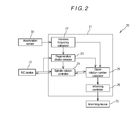
- Fig. 2 is a block diagram showing a configuration of the spindle rotation number controller.
- This NC machine tool 1 includes a bed 2, a column 3 erected on the bed 2, a spindle head 4 provided on a front surface (machining-area-side surface) of the column 3 to be movable in the Z-axis direction indicated by an arrow, a spindle 5 held by the spindle head 4 to be rotatable about its axis, a saddle 6 provided on the bed 2 below the spindle head 4 to be movable in the Y-axis direction indicated by an arrow, a table 7 arranged on the saddle 6 to be movable in the X-axis direction indicated by an arrow, a feed mechanism (not shown) moving the spindle head 4, the saddle 6 and the table 7 in their respective axis directions, a spindle motor (not shown) rotating the spindle 5, and an NC device 10 numerically controlling the feed mechanism (not shown), the spindle motor (not shown) and so on.
- the X axis the X axis
- the feed mechanism (not shown) and the spindle motor (not shown) are driven under control by the NC device 10, and thereby the spindle 5 is rotated about its axis and the spindle 5 and the table 7 are relatively moved in a three-dimensional space.
- the NC device 10 drives the feed mechanism (not shown) and the spindle motor (not shown) in accordance with an internally stored NC program, for example, a workpiece W placed and fixed on the table 7 is machined as appropriate by a tool T attached to the spindle 5.
- the spindle rotation number controller 20 of the present embodiment consists of a calculator 21, an acceleration sensor 30 installed on an outer peripheral surface of the spindle 5, and an informing device 35 connected to the calculator 21.
- the acceleration sensor 30 detects acceleration of the spindle 5, in other words, acceleration (i.e. vibration) transmitted from the tool T attached to the spindle 5.
- acceleration i.e. vibration
- the acceleration sensor 30 detects vibration transmitted to the spindle 5 from the tool T (vibration caused by the tool T) and outputs a signal corresponding to the vibration.
- the informing device 35 is composed of a display for displaying a screen and displays a screen relating to a stable rotation number.
- the calculator 21 consists of hardware such as CPU, ROM, and RAM, software stored in an appropriate memory such as ROM and RAM, and so on.
- the calculator 21 functions as various functional units: a vibration frequency calculator 22, a regenerative chatter detector 23, a stable rotation number calculator 25, a spindle rotation controller 24, and an informing controller 26.
- the vibration frequency calculator 22 inputs an output signal from the acceleration sensor 30 and performs the Fourier analysis thereon, and determines the most numerous frequency component to be a vibration frequency of the tool T and transmits it to the regenerative chatter detector 23 and the stable rotation number calculator 25. It is noted that this vibration frequency calculation process is continuously performed at predetermined sampling intervals during cutting.
- the regenerative chatter detector 23 receives the vibration frequency of the tool T calculated by the vibration frequency calculator 22 from the vibration frequency calculator 22 and receives the then rotation number of the spindle 5 from the NC device 10, and compares the vibration frequency of the tool T with the rotation number of the spindle 5 (hereinafter, referred to as "the spindle rotation number"), thereby determining whether regenerative chatter vibration occurs in the tool T.
- the regenerative chatter detector 23 compares the vibration frequency of the tool T with a frequency band (spindle rotation frequency band) obtained by adding a predetermined margin to a frequency corresponding to the product of multiplication of the spindle rotation number and the number of teeth of the tool T (spindle rotation frequency); when the vibration frequency of the tool T is out of the spindle rotation frequency band, the regenerative chatter detector 23 determines that regenerative chatter vibration occurs in the tool T, and transmits a regenerative chatter detection signal to the spindle rotation controller 24 and the stable rotation number calculator 25.
- a frequency band spindle rotation frequency band
- the frequency obtained by multiplying the spindle rotation number by the number of teeth of the tool T is a vibration frequency caused by contact of the teeth of the tool T with the workpiece W, and therefore it is a normal vibration frequency.
- other vibration frequencies can be regarded as abnormal vibration frequencies, that is, vibration frequencies related to regenerative chatter vibration.
- the spindle rotation controller 24 transmits to the NC device 10 a signal for gradually decreasing the spindle rotation number.
- the signal for gradually decreasing the spindle rotation number may be a special signal, it is preferred that the signal is an override signal for adjusting the spindle rotation number that follows a present command. Because a typical NC device 10 has an override function, if the spindle rotation number is decreased using this override function, it is not necessary to improve the NC device 10 and it is possible to prevent increase of the device cost.
- the spindle rotation controller 24 transmits gradually decreased override values (percentages), such as 99%, 98%, and 97%, to the NC device 10 at predetermined time intervals. Thereby, the spindle rotation number is gradually decreased under control by the NC device 10.
- the spindle rotation controller 24 cancels the above-described process of gradually decreasing the spindle rotation number, and transmits a correction signal to the NC device 10 in order to correct the spindle rotation number during cutting to the received stable rotation number n i , thereby correcting the rotation number of the spindle 5.
- the correction signal may be a special signal containing data relating to a correction rotation number; however, similarly to the above, it is preferred that it is an override signal for adjusting the spindle rotation number set in an NC program to the correction rotation number.
- the spindle rotation controller receives data relating to a plurality of stable rotation numbers n i , the spindle rotation number is corrected so that it becomes the largest one of the stable rotation numbers.
- the stable rotation number calculator 25 starts to operate after receiving the regenerative chatter detection signal from the regenerative chatter detector 23.
- the spindle rotation number calculator 25 monitors variation of the vibration frequency of the tool T transmitted from the vibration frequency calculator 22, and when the variation of the vibration frequency exceeds a predetermined reference value, the stable rotation number calculator 25 calculates a stable rotation number n i [min -1 ] as a candidate in accordance with Equations 1 and 2 below based on a frequency f [Hz] immediately before the variation of the vibration frequency exceeds the reference value and the then spindle rotation number n [min -1 ], and transmits data relating to the calculated stable rotation number n i to the spindle rotation controller 24 and the informing controller 26.
- the variation of the vibration frequency can be calculated by calculating the differences between the vibration frequencies successively transmitted from the vibration frequency calculator 22.
- the spindle rotation number n is received from the NC device 10 through the spindle rotation controller 24.
- the correspondence curve between spindle rotation number n and frequency of regenerative chatter vibration is divided at several spindle rotation numbers n as shown in Fig. 4(b) , and manners of variation of the divided curves are different from each other. That is, when regenerative chatter vibration occurs, if the variation of the vibration frequency of the tool T is monitored is monitored while, for example, the spindle rotation number is gradually decreased, at a certain point, the vibration frequency suddenly increases, that is, the variation of the vibration frequency becomes extremely large and exceeds a predetermined reference value.
- the spindle rotation number at which the variation of the vibration frequency exceeds the predetermined reference value is a rotation number that corresponds to a stable pocket
- the spindle rotation number at which the variation of the vibration frequency exceeds the predetermined reference value is a stable rotation number.
- the predetermined reference value is for detecting a singular point of the variation of the vibration frequency and is previously determined as appropriate to allow the singular point to be detected.
- the vibration frequency f immediately before the variation exceeds the predetermined reference value is a value close to a resonant frequency (natural frequency f r ) of the tool T. Therefore, ((f x 60) / N) in Equation 1 above can be regarded as ((f r x 60) / N) and corresponds to a spindle rotation number at the stable pocket 1. Therefore, the integer i b approximately calculated by dividing ((f x 60) / N) by the then spindle rotation number n is an index indicating the ordinal number of the stable pocket to which the spindle rotation number n corresponds.
- the stable rotation number calculator 25 monitors variation of the vibration frequency of the tool T transmitted from the vibration frequency calculator 22 (variation indicated by the curve D).
- 1125 [min -1 ] can be regarded as a stable rotation number at the 4th stable pocket.
- the stable rotation number calculator 25 calculates stable spindle rotation numbers n i as candidates in this matter and transmits data relating to the calculated stable rotation numbers n i to the spindle rotation controller 24 and the informing controller 26. It is noted that the integer i b can become 1 depending on the spindle rotation number n when regenerative chatter vibration occurs, and in this case, only the stable rotation number n 1 corresponding to the "stable pocket 1" is calculated.
- the informing controller 26 is a functional unit that controls for screen display on the informing device 35, and displays a screen showing information relating to the stable rotation number n i calculated by the stable rotation number calculator 25 on the informing device 35.
- a text screen showing the stable rotation number n i can be given as an example.
- vibration caused by the tool T is detected by the acceleration sensor 30 and a signal corresponding to the vibration is input to the vibration frequency calculator 22.
- the vibration frequency calculator 22 performs the Fourier analysis on the vibration signal input from the acceleration sensor 30 at least during cutting, determines the most numerous frequency component to be a vibration frequency of the tool T, and transmits the vibration frequency of the tool T to the regenerative chatter detector 23 and the stable rotation number calculator 25.
- the regenerative chatter detector 23 compares the vibration frequency of the tool T calculated by the vibration frequency calculator 22 with the then rotation number of the spindle 5 and determines whether regenerative chatter vibration occurs in the tool T. In the case where it is determined that regenerative chatter vibration occurs, the regenerative chatter detector 23 transmits a regenerative chatter detection signal to the spindle rotation controller 24 and the stable rotation number calculator 25.
- the spindle rotation controller 24 Upon receipt of the generative chatter detection signal from the regenerative chatter detector 23, the spindle rotation controller 24 transmits to the NC device 10 a signal for gradually decreasing the spindle rotation number to gradually decrease the spindle rotation number.
- the stable rotation number calculator 25 monitors variation of the vibration frequency of the tool T transmitted from the vibration frequency calculator 22, and when the variation of the vibration frequency exceeds a predetermined reference value, the stable rotation number calculator 25 calculates a stable rotation number n i [min -1 ] as a candidate in accordance with Equations 1 and 2 above based on a vibration frequency f [Hz] immediately before the vibration frequency exceeded a predetermined reference value and the then spindle rotation number n [min -1 ], and transmits data relating to the calculated stable rotation number n i to the spindle rotation controller 24 and the informing controller 26.
- the spindle rotation controller 24 Upon receipt of the data relating to the stable rotation number n i from the stable rotation number calculator 25, the spindle rotation controller 24 cancels the process of gradually decreasing the spindle rotation number and transmits a correction signal to the NC device 10 to correct the rotation number of the spindle 5 to the stable rotation number n i .
- the informing controller 26 displays a screen showing information relating to the stable rotation number n i received from the stable rotation number calculator 25 on the informing device 35.
- a stable spindle rotation number n i can be determined by causing the regenerative chatter detector 23 to monitor whether regenerative chatter vibration occurs during cutting, and when regenerative chatter vibration occurs, causing the spindle rotation controller 24 to gradually decrease the spindle rotation number and the stable rotation number calculator 25 to monitor variation of a vibration frequency of the tool T; therefore, a stable spindle rotation number n i can be obtained automatically and precisely without requiring a troublesome and unstable previous operation which has conventionally been required.
- the regenerative chatter vibration can be automatically eliminated without requiring an operator to take any action since the spindle rotation number during the cutting is automatically corrected to the stable spindle rotation number n i by the spindle rotation controller 24; therefore, stable machining is achieved. Further, this process enables a workpiece to be prevented from becoming a defective product due to regenerative chatter vibration.
- the stable rotation number n i calculated by the stable rotation number calculator 25 is displayed on the informing device 35, when regenerative chatter vibration occurs, the operator can easily recognize the stable spindle rotation number that is capable of eliminating the regenerative chatter vibration, and therefore can take actions such as changing a corresponding spindle rotation number provided in an NC program stored in the NC device 10 to the displayed stable rotation number n i .
- the spindle rotation controller 24 is configured to, in the case where a plurality of stable rotation numbers n i are calculated by the stable rotation number calculator 25, correct the spindle rotation number during cutting to the largest stable rotation number n i ; therefore, it is possible to eliminate the regenerative chatter vibration without lowering machining efficiency.
- the NC program editing apparatus 40 of the present embodiment is an apparatus obtained by embodying the present invention as an NC program editing apparatus, and, as shown in Fig. 3 , the configuration of a calculator 41 of the NC program editing apparatus 40 is different from that of the calculator 21 of the above-described spindle rotation number controller 20 only in that it has an NC program editor 42. Except for this, the NC program editing apparatus 40 has the same configuration as that of the above-described spindle rotation number controller 20. Therefore, the same components are denoted by the same reference numerals and detail explanation thereof is omitted.
- the NC program editor 42 is connected to the NC device 10. Upon receipt of data relating to the stable rotation number n i from the stable rotation number calculator 25, the NC program editor 42 changes the corresponding spindle rotation number in the NC program stored in the NC device 10 to the transmitted stable rotation number n i after the cutting operation being executed is finished.
- a corresponding NC program is read out from the NC device 10 and a corresponding S code in the NC program is detected, a numeral value for the spindle rotation number in the S code is replaced with a numeral value for the stable spindle rotation number n i , and then the corresponding NC program stored in the NC device 10 is overwritten with the edited NC program to store the edited NC program into the NC device 10.
- the NC program editor 42 may correct the corresponding spindle rotation number in the NC program to the largest one of the stable rotation numbers n i or to a stable rotation number which is freely selected from the rotation numbers.
- a spindle rotation number set in an NC program is a rotation number that causes regenerative chatter vibration
- the spindle rotation number is automatically corrected to a stable rotation number by the NC program editor 42; therefore, an appropriate NC program that does not cause regenerative chatter vibration can be automatically obtained without bothering an operator and the NC program is prevented from remaining uncorrected. Therefore, when machining is performed using the NC program thereafter, the machining is certainly stable.
- the spindle rotation controller 24 is configured to gradually decrease the spindle rotation number when regenerative chatter vibration has been detected by the regenerative chatter detector 23, the present invention is not limited thereto and the spindle rotation controller 24 may be configured to gradually increase the spindle rotation number when regenerative chatter vibration has been detected by the regenerative chatter detector 23.
- the spindle rotation number at which the variation of the vibration frequency exceeds the predetermined reference value can be also checked by gradually increasing the spindle rotation number. Therefore, also when the spindle rotation controller 24 is configured to gradually increase the spindle rotation number, a stable rotation number n i can be calculated by the stable rotation number calculator 25.
- the stable rotation number calculator 25 is configured to calculate a stable rotation number n i as a candidate in accordance with Equations 1 and 2 above based on a vibration frequency immediately after the variation of the vibration frequency exceeded the predetermined reference value.
- the spindle rotation controller 24 may be configured to, in the case where a plurality of stable rotation numbers n i are calculated by the stable rotation number calculator 25, sequentially correct the spindle rotation number for cutting in order starting with the smallest one of the calculated stable rotation numbers while referring to the results of the detection by the regenerative chatter detector 23.
- the stable rotation number n i is a spindle rotation number that does not cause regenerative chatter vibration; therefore, taking into account machining efficiency, it is preferred that the spindle rotation number is corrected to the largest stable rotation number n i However, if the spindle rotation number is suddenly corrected to the largest stable rotation number n i , an unexpected defect can occur; therefore, it is preferred that the spindle rotation number is sequentially corrected in order starting with the smallest one of the calculated stable rotation numbers while referring to the results of the detection by the regenerative chatter detector 23. Also in this configuration, it is possible to appropriately eliminate regenerative chatter vibration without lowering machining efficiency.
- the stable rotation number calculator 25 is configured to calculate a plurality of stable rotation numbers n i as candidates in accordance with Equations 1 and 2 above, the present invention is not limited thereto and the stable rotation number calculator 25 may be configured to simply determine a spindle rotation number at which the variation of the vibration frequency of the tool T exceeds the predetermined reference value to be a stable rotation number. In a case where machining efficiency is not regarded as important, regenerative chatter vibration can be eliminated also by this configuration.
- the informing device 35 is composed of a display
- the present invention is not limited thereto and the informing device 35 may be composed of an audio output device, such as a speaker.
- the informing controller 26 is configured to control the audio output device.
- the present invention is not limited thereto and the vibration data may be obtained by, for example, arranging a microphone at an upper position in the machining area of the NC machine tool and collecting cutting sounds during cutting by the microphone. Because the cutting sounds are caused by vibration of the tool T, the vibration state of the tool T can be detected by analyzing the cutting sounds.
Landscapes
- Engineering & Computer Science (AREA)
- Human Computer Interaction (AREA)
- Manufacturing & Machinery (AREA)
- Physics & Mathematics (AREA)
- General Physics & Mathematics (AREA)
- Automation & Control Theory (AREA)
- Automatic Control Of Machine Tools (AREA)
- Numerical Control (AREA)
Abstract
Description
- The present invention relates to a method of calculating a spindle rotation number capable of suppressing regenerative chatter vibration in cutting using a machine tool, a method of informing the spindle rotation number, a spindle rotation number controlling method, and an NC program editing method, and apparatus for performing these methods.
- It has conventionally been well known that machining accuracy (in particular, surface accuracy) deteriorates due to chatter vibration when machining a workpiece using a machine tool. Such chatter vibration is roughly classified into forced chatter vibration and self-exited chatter vibration, and it has been considered that forced chatter vibration occurs when an excessive external force is applied or when a frequency of an external force is synchronized with a resonant frequency of a vibrating system. On the other hand, self-exited chatter vibration includes regeneration type chatter vibration (regenerative chatter vibration) and mode-coupling type chatter vibration, and it has been considered that regenerative chatter vibration is caused by continuing cutting in which periodic variation of cutting resistance and periodic variation of thickness of cut are increased by interaction between them (the so-called "regeneration effect") and it has been considered that mode-coupling type chatter vibration is caused by the fact that vibration modes in two directions are coupled together when their resonant frequencies are close to each other.
- Further, conventionally, as a method of suppressing regenerative chatter vibration, which is one of the above-mentioned various type of chatter vibration, there has been proposed a method in which a stability limit diagram (diagram showing a stability limit in width of cut with respect to spindle rotation number; width of cut = depth of cut) as shown in
Fig. 4(a) is obtained and a spindle rotation number is adjusted so that it is positioned in a stable area. Further, a machining data correction method that is an improvement of the method is disclosed inPatent Literature 1 listed below. - As shown in
Fig. 4(a) , in the stability limit diagram, there are a plurality of areas called stable pockets (for example, a "stable pocket 1", a "stable pocket 2", and a "stable pocket 3") where no regenerative chatter vibration occurs even if the depth of cut is large, and spindle rotation numbers around the stable pockets are regarded as stable spindle rotation numbers. Further, when a natural frequency of a tool is represented by fr [Hz] and the number of teeth of the tool is represented by N, a spindle rotation number n1 [min-1] at the "stable pocket 1", which is the largest spindle rotation number, is represented as n1 = fr x 60 / N, a spindle rotation number n2 at the "stable pocket 2" is represented as n2 = fr x 60 / (N x 2), and a spindle rotation number n3 at the "stable pocket 3" is represented as n3 = fr x 60 / (N x 3). Thus, a spindle rotation number nm at a "stable pocket m" which is the mth stable pocket is represented as nm = fr x 60 / (N x m) (m is a positive integer). Further, the higher the spindle rotation number is, the wider the stable area of the stable pocket is. - A basic method of obtaining the stability limit diagram is explained in detail in Non-Patent
Literature 1 and Non-Patent Literature 2 listed below. According toNon-Patent Literatures 
It is noted that, in the equation, Kf is a specific cutting resistance [N/mm2], G(ωc) is a real part of a compliance transfer function (ratio of vibration displacement output to force input) of a machine structure, and ωc is an angular frequency. - Further, the specific cutting resistance Kf is a force in a cutting direction when cutting a workpiece so that a chip with the thickness of 1 mm and the cross-sectional area of 1 mm2 is produced. For example, as disclosed in
Patent Literature 1, the specific cutting resistance Kf can be calculated from a value of current flowing through a spindle motor when performing a test cutting on an appropriate workpiece using a tool to be used. - Further, the real part G(ωc) of the compliance transfer function is obtained by attaching a vibration detector (acceleration sensor) to a tip end of a tool attached to a spindle of a machine tool and then striking the tip end portion of the tool with an impact hammer having a force sensor (load cell) attached to its striking portion, and processing the resultant output signal of the acceleration sensor (signal relating to free vibration of the tool) and output signal of the force sensor (signal relating to the striking force) using a dedicated processor, which is summarized and disclosed also in
Patent Literature 1. -
- [Patent Literature 1] Japanese Unexamined Patent Application Publication No.
2013-43240 -
- [Non-Patent Literature 1] Eiji Shamoto: "Mechanism and Suppression of Chatter Vibrations in Cutting", Electric Furnace Steel, Vol. 82 No. 2, 2011
- [Non-Patent Literature 2] Norikazu Suzuki: "Chatter Vibration in Cutting,
- However, as described above, in the conventional method for suppressing regenerative chatter vibration, it is necessary to perform previous operations for obtaining a stability limit diagram, such as a test machining for obtaining a specific cutting resistance Kf and a striking test using an impact hammer for obtaining a real part G(ωc) of a compliance transfer function, and further, because the specific cutting resistance Kf and the real part G(ωc) of the compliance transfer function are values specific to a tool and a machine tool, it is necessary to perform the above-mentioned previous operations corresponding to a tool and a machine tool to be used; therefore, there is a problem that the operations are troublesome and very annoying.
- Further, artificial variation easily occurs in the striking test using an impact hammer because the striking test is performed by a human, and there is also a technical problem that technical skills are required in striking itself in order to obtain appropriate data.
- Furthermore, as for a hammer tip to be attached to the striking portion of the impact hammer, it is necessary to calculate a period of a vibration frequency to be measured (a reciprocal of the frequency) and select a hammer tip by trial and error so that the time of contact of the hammer is within a range of about 0.3 to one times the period; therefore, the conventional method is troublesome also in this respect.
- The present invention has been achieved in view of the above-described circumstances, and an object thereof is to provide a method capable of, without performing a troublesome previous operation calculating a stable spindle rotation number that is capable of suppressing regenerative chatter vibration, an apparatus therefor, and so on.
- The present invention, for solving the above-mentioned problems, relates to a method of calculating a stable spindle rotation number capable of suppressing regenerative chatter vibration in cutting using a machine tool, including: a vibration frequency calculating step of calculating a vibration frequency of a tool by obtaining data on vibration caused by the tool in cutting and analyzing the obtained vibration data; a regenerative chatter detecting step of detecting whether regenerative chatter vibration occurs in the tool by comparing the vibration frequency of the tool calculated in the vibration frequency calculating process with a spindle rotation number; a rotation number changing step of gradually decreasing or increasing the spindle rotation number in a case where occurrence of regenerative chatter vibration is detected in the regenerative chatter detecting process; and/or a stable rotation number calculating step of monitoring variation of the vibration frequency of the tool calculated in the vibration frequency calculating process and determining a spindle rotation number when the variation of the vibration frequency exceeds a predetermined reference value to be a stable spindle rotation number.
- Further, this method is suitably performed by a stable spindle rotation number calculating apparatus having a configuration described below. That is, the stable spindle rotation number calculating apparatus may be configured to include: a vibration data obtainer that obtains data on vibration caused by a tool in cutting; a vibration frequency calculator that calculates a vibration frequency of the tool by analyzing the vibration data obtained by the vibration data obtainer; a regenerative chatter detector that detects whether regenerative chatter vibration occurs in the tool by comparing the vibration frequency of the tool calculated by the vibration frequency calculator with a spindle rotation number; a spindle rotation controller that gradually decreases or increases the spindle rotation number in a case where occurrence of regenerative chatter vibration is detected by the regenerative chatter detector; and/or a stable rotation number calculator that monitors variation of the vibration frequency of the tool calculated by the vibration frequency calculator and determines a spindle rotation number when the variation of the vibration frequency exceeds a predetermined reference value to be a stable spindle rotation number.
- According to this calculating apparatus, first, data on vibration caused by a tool in cutting can be obtained by the vibration data obtainer and the obtained vibration data is preferably analyzed by the vibration frequency calculator to calculate a vibration frequency of the tool, and the calculated vibration frequency is transmitted to the regenerative chatter detector (vibration frequency calculation step).
- The regenerative chatter detector preferably compares the vibration frequency of the tool calculated by the vibration frequency calculator with the then spindle rotation number and, when the vibration frequency of the tool is different from a frequency corresponding to the product of the spindle rotation number and the number of teeth of the tool, preferably determines that regenerative chatter vibration occurs in the tool (regenerative chatter detection step). It is noted that the obtaining of vibration data, the calculation of vibration frequency and the detection of regenerative chatter are preferably continuously executed at predetermined time intervals during cutting.
- Further, once occurrence of regenerative chatter vibration is detected by the regenerative chatter detector, the spindle rotation controller preferably gradually decreases or increases the spindle rotation number (rotation number change step) and the stable rotation number calculator preferably monitors variation of the vibration frequency of the tool calculated by the vibration frequency calculator and, when the variation of the vibration frequency exceeds a predetermined reference value, preferably determines the then spindle rotation number to be a stable spindle rotation number (stable rotation number calculation step). It is noted that the variation of the vibration frequency can be grasped by calculating differences between the vibration frequencies transmitted successively from the vibration frequency calculator.
-
Fig. 4(b) is a diagram showing a relationship between spindle rotation number and frequency of regenerative chatter vibration, where a curve indicating the frequency of regenerative chatter vibration corresponding to the spindle rotation number is divided at several spindle rotation numbers and manners of variation of the divided curves are different from each other. That is, when regenerative chatter vibration occurs, if the variation of the vibration frequency of the tool calculated by the vibration frequency calculator is monitored while, for example, the spindle rotation number is gradually decreased, at a certain point, the vibration frequency suddenly increases, that is, the variation of the vibration frequency becomes extremely large, in other words, exceeds a predetermined reference value. For example, inFig. 4(b) , if the spindle rotation number is gradually decreased from 5000 [min-1], the vibration frequency gradually decreases along the curve A and sharply increases from about 147 [Hz] to about 177 [Hz] around the spindle rotation number of 4600 [min-1], and then gradually decreases along the curve B. - As understood by referring to
Figs. 4(a) and 4(b) , the spindle rotation number at which the variation exceeds the predetermined reference value is a rotation number that corresponds to a stable pocket, and the spindle rotation number at which the variation of the vibration frequency exceeds the predetermined reference value can be determined to be a stable spindle rotation number. It is noted that the spindle rotation number at which the variation of the vibration frequency exceeds the predetermined reference value can be checked also by gradually increasing the spindle rotation number. Therefore, in the present invention, in the case where occurrence of regenerative chatter vibration is detected by the regenerative chatter detector, the spindle rotation number is gradually decreased or increased by the spindle rotation controller. Further, the predetermined reference value is for detecting a singular point of the variation of the vibration frequency and is previously determined as appropriate to allow the singular point to be detected. - Thus, according to the present invention, a stable spindle rotation number can be determined by monitoring whether regenerative chatter vibration occurs during cutting and, when regenerative chatter vibration occurs, gradually decreasing or increasing the spindle rotation number and monitoring variation of the vibration frequency of the tool; therefore, a stable spindle rotation number can be obtained automatically and precisely without requiring a troublesome and unstable previous operation which has conventionally been required.
- Further, in the present invention, in the stable rotation number calculation step executed by the stable rotation number calculator, a stable rotation number ni may preferably be calculated by using
Equations 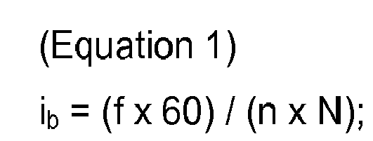

where f [Hz] is a vibration frequency immediately before the variation of the vibration frequency exceeds the predetermined reference value in the case where the spindle rotation controller gradually decreases the spindle rotation number, or a vibration frequency immediately after the variation of the vibration frequency exceeds the predetermined reference value in the case where the spindle rotation controller gradually increases the spindle rotation number, n [min-1] is a spindle rotation number when the variation of the vibration frequency exceeds the predetermined reference value, N is the number of teeth of the tool, and ib is a positive integer. The integer ib is first approximately calculated byEquation 1 and then a stable rotation number ni is calculated byEquation 2 based on a positive integer i equal to or smaller than the calculated integer ib. - As seen from
Fig. 4(b) , the vibration frequency f is a value close to a resonant frequency of the tool (the natural frequency fr). Therefore, ((f x 60) / N) represents a spindle rotation number at thestable pocket 1 and the integer ib obtained by dividing ((f x 60) / N) by the then spindle rotation number is an index indicating the ordinal number of the stable pocket to which the spindle rotation number n corresponds. If ib is approximate to the integer "4", the spindle rotation number n is regarded as a spindle rotation number corresponding to thestable pocket 4. Then, a spindle rotation number n3 that is obtained by substituting "3", which is an integer smaller than "4", for i inEquation 2 is a spindle rotation number corresponding to the "stable pocket 3", a spindle rotation number n2 that is obtained by substituting "2" for i is a spindle rotation number corresponding to the "stable pocket 2", and a spindle rotation number n1 that is obtained by substituting "1" for i is a spindle rotation number corresponding to the "stable pocket 1". Thus, a stable spindle rotation number ni can be calculated by usingEquations - Further, in the present invention, an informer may preferably be further provided for informing the operator of the stable rotation number calculated by the stable rotation number calculator (informing step). When thus configured, in a case where regenerative chatter vibration occurs, the operator can easily obtain and recognize a stable spindle rotation number capable of eliminating the regenerative chatter vibration. It is noted that the stable rotation number may be informed by displaying it on a display or may be informed by outputting it by voice through a speaker.
- Further, in the present invention, the spindle rotation controller may preferably be configured to further correct the spindle rotation number for cutting to the stable rotation number calculated by the stable rotation number calculator (rotation number correction step). In this configuration, even if regenerative chatter vibration occurs during cutting, the regenerative chatter vibration can be automatically eliminated without requiring the operator to take any action; therefore, stable machining is achieved. Further, it is possible to prevent a workpiece from becoming a defective product due to regenerative chatter vibration.
- Further, in the present invention, the spindle rotation controller may preferably be configured to, in a case where a plurality of stable rotation numbers are calculated, in the rotation number correction step, sequentially correct the spindle rotation number for cutting in order starting with the smallest one of the calculated stable rotation numbers while referring to the detection results in the regenerative chatter detection step. In this configuration, it is possible to eliminate regenerative chatter vibration without lowering machining efficiency.
- Further, in the present invention, an NC program editor may preferably be further provided for correcting a spindle rotation number set in an NC program to the stable rotation number calculated by the stable rotation number calculator (NC program correction step). According to this configuration, in a case where a spindle rotation number set in an NC program is a rotation number that causes regenerative chatter vibration, the spindle rotation number is automatically corrected to a stable rotation number by the NC program editor; therefore, an appropriate NC program that does not cause regenerative chatter vibration can be automatically obtained without bothering the operator and the NC program is prevented from remaining uncorrected. Therefore, when machining is performed using the NC program thereafter, the machining is certainly stable.
- It is noted that, in the case where a plurality of stable rotation numbers are calculated by the stable rotation number calculator in the stable rotation number calculation step, the NC program editor may, in the NC program correction step, preferably correct the spindle rotation number set in the NC program to the largest stable rotation number or freely select one of the calculated stable rotation numbers and correct the spindle rotation number set in the NC program to the selected stable rotation number.
- As described above, according to the present invention, a stable spindle rotation number can be determined by monitoring whether regenerative chatter vibration occurs during cutting and, when regenerative chatter vibration occurs, gradually decreasing or increasing the spindle rotation number and monitoring variation of the vibration frequency of the tool; therefore, a stable spindle rotation number can be obtained automatically and precisely without requiring a troublesome and unstable previous operation which has conventionally been required.
- Additionally, if an informer provided for informing an operator of a stable rotation number, when regenerative chatter vibration occurs, the operator can easily obtain and recognize a stable spindle rotation number capable of eliminating the regenerative chatter vibration.
- Further, if the spindle rotation controller is configured to correct the spindle rotation number for cutting to a stable rotation number calculated by the stable rotation number calculator, even if regenerative chatter vibration occurs during cutting, the regenerative chatter vibration can be automatically eliminated without requiring the operator to take any action; therefore, stable machining is achieved.
- Further, if an NC program editor is provided for correcting a spindle rotation number set in an NC program to a stable rotation number calculated by the stable rotation number calculator, in a case where a spindle rotation number set in an NC program is a rotation number that causes regenerative chatter vibration, the spindle rotation number is automatically corrected to a stable rotation number; therefore, an appropriate NC program that does not cause regenerative chatter vibration can be automatically obtained without bothering the operator.
-
-
Fig. 1 is an explanatory diagram showing a schematic configuration of an NC machine tool and a spindle rotation number controller according to a first embodiment of the present invention; -
Fig. 2 is a block diagram showing a schematic configuration of the spindle rotation number controller according to the first embodiment of the present invention; -
Fig. 3 is a block diagram showing a schematic configuration of an NC program editing apparatus according to a second embodiment of the present invention; and -
Fig. 4 shows explanatory diagrams for explaining a stable spindle rotation number; (a) is a stability limit diagram showing a stability limit in width of cut with respect to spindle rotation number and (b) is a diagram showing a relationship between spindle rotation number and frequency of regenerative chatter vibration. - Specific exemplary preferred embodiments of the present invention will be described below with reference to the drawings. That is, in the following, preferred aspects and exemplary embodiments will be described in more detail with reference to the accompanying figures. Same or similar features in different drawings and embodiments are sometimes referred to by similar reference numerals. It is to be understood that the detailed description below relating to various preferred aspects and preferred embodiments are not to be meant as limiting the scope of the present invention.
-
Fig. 1 is an explanatory diagram showing a schematic configuration of a spindle rotation number controller and an NC machine tool to which the spindle rotation number controller is attached according to a first embodiment, andFig. 2 is a block diagram showing a configuration of the spindle rotation number controller. - First, a summary of the
NC machine tool 1 is described. ThisNC machine tool 1 includes abed 2, acolumn 3 erected on thebed 2, aspindle head 4 provided on a front surface (machining-area-side surface) of thecolumn 3 to be movable in the Z-axis direction indicated by an arrow, aspindle 5 held by thespindle head 4 to be rotatable about its axis, asaddle 6 provided on thebed 2 below thespindle head 4 to be movable in the Y-axis direction indicated by an arrow, a table 7 arranged on thesaddle 6 to be movable in the X-axis direction indicated by an arrow, a feed mechanism (not shown) moving thespindle head 4, thesaddle 6 and the table 7 in their respective axis directions, a spindle motor (not shown) rotating thespindle 5, and anNC device 10 numerically controlling the feed mechanism (not shown), the spindle motor (not shown) and so on. It is noted that the X axis, the Y axis, and the Z axis are orthogonal to one another. - Thus, in this
NC machine tool 1, the feed mechanism (not shown) and the spindle motor (not shown) are driven under control by theNC device 10, and thereby thespindle 5 is rotated about its axis and thespindle 5 and the table 7 are relatively moved in a three-dimensional space. Further, for example, when theNC device 10 drives the feed mechanism (not shown) and the spindle motor (not shown) in accordance with an internally stored NC program, for example, a workpiece W placed and fixed on the table 7 is machined as appropriate by a tool T attached to thespindle 5. - Next, the spindle
rotation number controller 20 of the present embodiment is described. As shown inFigs. 1 and2 , the spindlerotation number controller 20 of the present embodiment consists of acalculator 21, anacceleration sensor 30 installed on an outer peripheral surface of thespindle 5, and an informingdevice 35 connected to thecalculator 21. - The
acceleration sensor 30 detects acceleration of thespindle 5, in other words, acceleration (i.e. vibration) transmitted from the tool T attached to thespindle 5. When cutting the workpiece W using the rotating tool T, vibration occurs in the tool T due to cutting resistance in the cutting; theacceleration sensor 30 detects vibration transmitted to thespindle 5 from the tool T (vibration caused by the tool T) and outputs a signal corresponding to the vibration. - The informing
device 35 is composed of a display for displaying a screen and displays a screen relating to a stable rotation number. - The
calculator 21 consists of hardware such as CPU, ROM, and RAM, software stored in an appropriate memory such as ROM and RAM, and so on. When the software is executed, thecalculator 21 functions as various functional units: avibration frequency calculator 22, aregenerative chatter detector 23, a stablerotation number calculator 25, aspindle rotation controller 24, and an informingcontroller 26. - During cutting of the workpiece W using the tool T, the
vibration frequency calculator 22 inputs an output signal from theacceleration sensor 30 and performs the Fourier analysis thereon, and determines the most numerous frequency component to be a vibration frequency of the tool T and transmits it to theregenerative chatter detector 23 and the stablerotation number calculator 25. It is noted that this vibration frequency calculation process is continuously performed at predetermined sampling intervals during cutting. - The
regenerative chatter detector 23 receives the vibration frequency of the tool T calculated by thevibration frequency calculator 22 from thevibration frequency calculator 22 and receives the then rotation number of thespindle 5 from theNC device 10, and compares the vibration frequency of the tool T with the rotation number of the spindle 5 (hereinafter, referred to as "the spindle rotation number"), thereby determining whether regenerative chatter vibration occurs in the tool T. More specifically, theregenerative chatter detector 23 compares the vibration frequency of the tool T with a frequency band (spindle rotation frequency band) obtained by adding a predetermined margin to a frequency corresponding to the product of multiplication of the spindle rotation number and the number of teeth of the tool T (spindle rotation frequency); when the vibration frequency of the tool T is out of the spindle rotation frequency band, theregenerative chatter detector 23 determines that regenerative chatter vibration occurs in the tool T, and transmits a regenerative chatter detection signal to thespindle rotation controller 24 and the stablerotation number calculator 25. The frequency obtained by multiplying the spindle rotation number by the number of teeth of the tool T is a vibration frequency caused by contact of the teeth of the tool T with the workpiece W, and therefore it is a normal vibration frequency. On the other hand, other vibration frequencies can be regarded as abnormal vibration frequencies, that is, vibration frequencies related to regenerative chatter vibration. - When receiving the regenerative chatter vibration signal from the
regenerative chatter detector 23, thespindle rotation controller 24 transmits to the NC device 10 a signal for gradually decreasing the spindle rotation number. Although the signal for gradually decreasing the spindle rotation number may be a special signal, it is preferred that the signal is an override signal for adjusting the spindle rotation number that follows a present command. Because atypical NC device 10 has an override function, if the spindle rotation number is decreased using this override function, it is not necessary to improve theNC device 10 and it is possible to prevent increase of the device cost. It is noted that, in the case of decreasing the spindle rotation number by the override signal, thespindle rotation controller 24 transmits gradually decreased override values (percentages), such as 99%, 98%, and 97%, to theNC device 10 at predetermined time intervals. Thereby, the spindle rotation number is gradually decreased under control by theNC device 10. - Further, when receiving data relating to a stable rotation number ni calculated by the stable
rotation number calculator 25, which will be described in detail later, thespindle rotation controller 24 cancels the above-described process of gradually decreasing the spindle rotation number, and transmits a correction signal to theNC device 10 in order to correct the spindle rotation number during cutting to the received stable rotation number ni, thereby correcting the rotation number of thespindle 5. It is noted that the correction signal may be a special signal containing data relating to a correction rotation number; however, similarly to the above, it is preferred that it is an override signal for adjusting the spindle rotation number set in an NC program to the correction rotation number. In this configuration, it is not necessary to improve theNC device 10 and it is possible to prevent increase of the device cost. Further, in a case where the spindle rotation controller receives data relating to a plurality of stable rotation numbers ni, the spindle rotation number is corrected so that it becomes the largest one of the stable rotation numbers. - The stable
rotation number calculator 25 starts to operate after receiving the regenerative chatter detection signal from theregenerative chatter detector 23. The spindlerotation number calculator 25 monitors variation of the vibration frequency of the tool T transmitted from thevibration frequency calculator 22, and when the variation of the vibration frequency exceeds a predetermined reference value, the stablerotation number calculator 25 calculates a stable rotation number ni [min-1] as a candidate in accordance withEquations spindle rotation controller 24 and the informingcontroller 26. It is noted that the variation of the vibration frequency can be calculated by calculating the differences between the vibration frequencies successively transmitted from thevibration frequency calculator 22. Further, the spindle rotation number n is received from theNC device 10 through thespindle rotation controller 24.
and
where N is the number of teeth of the tool T, ib is a positive integer, and i is a positive integer equal to or smaller than ib. - As has been described using
Fig. 4 , the correspondence curve between spindle rotation number n and frequency of regenerative chatter vibration is divided at several spindle rotation numbers n as shown inFig. 4(b) , and manners of variation of the divided curves are different from each other. That is, when regenerative chatter vibration occurs, if the variation of the vibration frequency of the tool T is monitored is monitored while, for example, the spindle rotation number is gradually decreased, at a certain point, the vibration frequency suddenly increases, that is, the variation of the vibration frequency becomes extremely large and exceeds a predetermined reference value. - For example, in
Fig. 4(b) , if the spindle rotation number n is gradually decreased from 5000 [min-1], the vibration frequency gradually decreases along the curve A and sharply increases from about 147 [Hz] to about 177 [Hz] around the spindle rotation number of 4600 [min-1], and then gradually decreases along the curve B. As understood by referring toFigs. 4(a) and 4(b) , the spindle rotation number at which the variation of the vibration frequency exceeds the predetermined reference value is a rotation number that corresponds to a stable pocket, and the spindle rotation number at which the variation of the vibration frequency exceeds the predetermined reference value is a stable rotation number. It is noted that the predetermined reference value is for detecting a singular point of the variation of the vibration frequency and is previously determined as appropriate to allow the singular point to be detected. - Further, as seen from
Fig. 4(b) , the vibration frequency f immediately before the variation exceeds the predetermined reference value is a value close to a resonant frequency (natural frequency fr) of the tool T. Therefore, ((f x 60) / N) inEquation 1 above can be regarded as ((fr x 60) / N) and corresponds to a spindle rotation number at thestable pocket 1. Therefore, the integer ib approximately calculated by dividing ((f x 60) / N) by the then spindle rotation number n is an index indicating the ordinal number of the stable pocket to which the spindle rotation number n corresponds. - For example, if occurrence of regenerative chatter vibration is detected by the
regenerative chatter detector 23 when the spindle rotation number n is 1400 [min-1], and the stablerotation number calculator 25 receives a generative chatter detection signal from theregenerative chatter detector 23, the stablerotation number calculator 25 monitors variation of the vibration frequency of the tool T transmitted from the vibration frequency calculator 22 (variation indicated by the curve D). If the variation of the vibration frequency exceeds the predetermined reference value around the point where the spindle rotation number n becomes 1125 [min-1], the stablerotation number calculator 25 detects that the variation of the vibration frequency has exceeded the predetermined reference value, and calculates the integer ib as the stable pocket index as described below in accordance whichEquation 1 above, based on the vibration frequency f immediately before the variation of the vibration frequency exceeded the predetermined reference value, i.e. 147 [Hz], and the then spindle rotation number n, i.e. 1125 [min-1]. It is noted that the number of teeth N of the tool T is 2.
- Based on this result, 1125 [min-1] can be regarded as a stable rotation number at the 4th stable pocket.
- Subsequently, the stable
rotation number calculator 25 determines positive integers equal to or lower than the calculated ib (= 4), and substitutes them for i inEquation 2 above to calculate stable rotation numbers ni [min-1] as candidates. In this example, the stable rotation number n4 corresponding to the 4th stable pocket is
the stable rotation number n3 corresponding to the third stable pocket is
the stable rotation number n2 corresponding to the second stable pocket is
and
the stable rotation number n1 corresponding to the first stable pocket is
- The stable
rotation number calculator 25 calculates stable spindle rotation numbers ni as candidates in this matter and transmits data relating to the calculated stable rotation numbers ni to thespindle rotation controller 24 and the informingcontroller 26. It is noted that the integer ib can become 1 depending on the spindle rotation number n when regenerative chatter vibration occurs, and in this case, only the stable rotation number n1 corresponding to the "stable pocket 1" is calculated. - The informing
controller 26 is a functional unit that controls for screen display on the informingdevice 35, and displays a screen showing information relating to the stable rotation number ni calculated by the stablerotation number calculator 25 on the informingdevice 35. As for the screen displayed, a text screen showing the stable rotation number ni can be given as an example. - According to the spindle
rotation number controller 20 of the present embodiment having the above-described configuration, vibration caused by the tool T is detected by theacceleration sensor 30 and a signal corresponding to the vibration is input to thevibration frequency calculator 22. Then, thevibration frequency calculator 22 performs the Fourier analysis on the vibration signal input from theacceleration sensor 30 at least during cutting, determines the most numerous frequency component to be a vibration frequency of the tool T, and transmits the vibration frequency of the tool T to theregenerative chatter detector 23 and the stablerotation number calculator 25. - The
regenerative chatter detector 23 compares the vibration frequency of the tool T calculated by thevibration frequency calculator 22 with the then rotation number of thespindle 5 and determines whether regenerative chatter vibration occurs in the tool T. In the case where it is determined that regenerative chatter vibration occurs, theregenerative chatter detector 23 transmits a regenerative chatter detection signal to thespindle rotation controller 24 and the stablerotation number calculator 25. - Upon receipt of the generative chatter detection signal from the
regenerative chatter detector 23, thespindle rotation controller 24 transmits to the NC device 10 a signal for gradually decreasing the spindle rotation number to gradually decrease the spindle rotation number. - On the other hand, simultaneously with the process of decreasing the spindle rotation number by the
spindle rotation controller 24, the stablerotation number calculator 25 monitors variation of the vibration frequency of the tool T transmitted from thevibration frequency calculator 22, and when the variation of the vibration frequency exceeds a predetermined reference value, the stablerotation number calculator 25 calculates a stable rotation number ni [min-1] as a candidate in accordance withEquations spindle rotation controller 24 and the informingcontroller 26. - Upon receipt of the data relating to the stable rotation number ni from the stable
rotation number calculator 25, thespindle rotation controller 24 cancels the process of gradually decreasing the spindle rotation number and transmits a correction signal to theNC device 10 to correct the rotation number of thespindle 5 to the stable rotation number ni. - Further, the informing
controller 26 displays a screen showing information relating to the stable rotation number ni received from the stablerotation number calculator 25 on the informingdevice 35. - Thus, according to the spindle
rotation number controller 20 of the present embodiment, a stable spindle rotation number ni can be determined by causing theregenerative chatter detector 23 to monitor whether regenerative chatter vibration occurs during cutting, and when regenerative chatter vibration occurs, causing thespindle rotation controller 24 to gradually decrease the spindle rotation number and the stablerotation number calculator 25 to monitor variation of a vibration frequency of the tool T; therefore, a stable spindle rotation number ni can be obtained automatically and precisely without requiring a troublesome and unstable previous operation which has conventionally been required. - Further, when regenerative chatter vibration occurs during cutting, the regenerative chatter vibration can be automatically eliminated without requiring an operator to take any action since the spindle rotation number during the cutting is automatically corrected to the stable spindle rotation number ni by the
spindle rotation controller 24; therefore, stable machining is achieved. Further, this process enables a workpiece to be prevented from becoming a defective product due to regenerative chatter vibration. - Further, since the stable rotation number ni calculated by the stable
rotation number calculator 25 is displayed on the informingdevice 35, when regenerative chatter vibration occurs, the operator can easily recognize the stable spindle rotation number that is capable of eliminating the regenerative chatter vibration, and therefore can take actions such as changing a corresponding spindle rotation number provided in an NC program stored in theNC device 10 to the displayed stable rotation number ni. - Further, the
spindle rotation controller 24 is configured to, in the case where a plurality of stable rotation numbers ni are calculated by the stablerotation number calculator 25, correct the spindle rotation number during cutting to the largest stable rotation number ni; therefore, it is possible to eliminate the regenerative chatter vibration without lowering machining efficiency. - Next, an NC program editing apparatus according to a second embodiment of the present invention will be described with reference to
Fig. 3 . - It is noted that the NC
program editing apparatus 40 of the present embodiment is an apparatus obtained by embodying the present invention as an NC program editing apparatus, and, as shown inFig. 3 , the configuration of acalculator 41 of the NCprogram editing apparatus 40 is different from that of thecalculator 21 of the above-described spindlerotation number controller 20 only in that it has anNC program editor 42. Except for this, the NCprogram editing apparatus 40 has the same configuration as that of the above-described spindlerotation number controller 20. Therefore, the same components are denoted by the same reference numerals and detail explanation thereof is omitted. - The
NC program editor 42 is connected to theNC device 10. Upon receipt of data relating to the stable rotation number ni from the stablerotation number calculator 25, theNC program editor 42 changes the corresponding spindle rotation number in the NC program stored in theNC device 10 to the transmitted stable rotation number ni after the cutting operation being executed is finished. - As a specific mode of this changing process, for example, a corresponding NC program is read out from the
NC device 10 and a corresponding S code in the NC program is detected, a numeral value for the spindle rotation number in the S code is replaced with a numeral value for the stable spindle rotation number ni, and then the corresponding NC program stored in theNC device 10 is overwritten with the edited NC program to store the edited NC program into theNC device 10. - It is noted that, in the case where a plurality of stable rotation numbers ni are calculated by the stable
rotation number calculator 25, theNC program editor 42 may correct the corresponding spindle rotation number in the NC program to the largest one of the stable rotation numbers ni or to a stable rotation number which is freely selected from the rotation numbers. - Thus, according to the NC
program editing apparatus 40 of the present embodiment, in the case where a spindle rotation number set in an NC program is a rotation number that causes regenerative chatter vibration, the spindle rotation number is automatically corrected to a stable rotation number by theNC program editor 42; therefore, an appropriate NC program that does not cause regenerative chatter vibration can be automatically obtained without bothering an operator and the NC program is prevented from remaining uncorrected. Therefore, when machining is performed using the NC program thereafter, the machining is certainly stable. - Although specific embodiments of the present invention have been described above, the present invention is not limited thereto and can be implemented as other embodiments.
- For example, although, in the above embodiments, the
spindle rotation controller 24 is configured to gradually decrease the spindle rotation number when regenerative chatter vibration has been detected by theregenerative chatter detector 23, the present invention is not limited thereto and thespindle rotation controller 24 may be configured to gradually increase the spindle rotation number when regenerative chatter vibration has been detected by theregenerative chatter detector 23. As seen fromFig. 4(b) , the spindle rotation number at which the variation of the vibration frequency exceeds the predetermined reference value can be also checked by gradually increasing the spindle rotation number. Therefore, also when thespindle rotation controller 24 is configured to gradually increase the spindle rotation number, a stable rotation number ni can be calculated by the stablerotation number calculator 25. It is noted that, in this case, the stablerotation number calculator 25 is configured to calculate a stable rotation number ni as a candidate in accordance withEquations - Further, the
spindle rotation controller 24 may be configured to, in the case where a plurality of stable rotation numbers ni are calculated by the stablerotation number calculator 25, sequentially correct the spindle rotation number for cutting in order starting with the smallest one of the calculated stable rotation numbers while referring to the results of the detection by theregenerative chatter detector 23. The stable rotation number ni is a spindle rotation number that does not cause regenerative chatter vibration; therefore, taking into account machining efficiency, it is preferred that the spindle rotation number is corrected to the largest stable rotation number ni However, if the spindle rotation number is suddenly corrected to the largest stable rotation number ni, an unexpected defect can occur; therefore, it is preferred that the spindle rotation number is sequentially corrected in order starting with the smallest one of the calculated stable rotation numbers while referring to the results of the detection by theregenerative chatter detector 23. Also in this configuration, it is possible to appropriately eliminate regenerative chatter vibration without lowering machining efficiency. - Further, although the stable
rotation number calculator 25 is configured to calculate a plurality of stable rotation numbers ni as candidates in accordance withEquations rotation number calculator 25 may be configured to simply determine a spindle rotation number at which the variation of the vibration frequency of the tool T exceeds the predetermined reference value to be a stable rotation number. In a case where machining efficiency is not regarded as important, regenerative chatter vibration can be eliminated also by this configuration. - Further, although, in the above embodiments, the informing
device 35 is composed of a display, the present invention is not limited thereto and the informingdevice 35 may be composed of an audio output device, such as a speaker. In this case, the informingcontroller 26 is configured to control the audio output device. - Further, although, in the above embodiments, the data on the vibration caused by the tool T is obtained using the
acceleration sensor 30 attached to thespindle 5, the present invention is not limited thereto and the vibration data may be obtained by, for example, arranging a microphone at an upper position in the machining area of the NC machine tool and collecting cutting sounds during cutting by the microphone. Because the cutting sounds are caused by vibration of the tool T, the vibration state of the tool T can be detected by analyzing the cutting sounds. - Features, components and specific details of the structures of the above-described embodiments may be exchanged or combined to form further embodiments optimized for the respective application. As far as those modifications are apparent for an expert skilled in the art they shall be disclosed implicitly by the above description without specifying explicitly every possible combination.
-
- 1
- NC machine tool
- 5
- Spindle
- 7
- Table
- T
- Tool
- W
- Workpiece
- 10
- NC device
- 20
- Spindle rotation number controller
- 21
- Calculator
- 22
- Vibration frequency calculator
- 23
- Regenerative chatter detector
- 24
- Spindle rotation controller
- 25
- Stable rotation number calculator
- 26
- Informing controller
- 30
- Acceleration sensor
- 35
- Informing device
Claims (14)
- A method of calculating a stable spindle rotation number capable of suppressing regenerative chatter vibration in cutting using a machine tool, comprising:a vibration frequency calculating process of calculating a vibration frequency of a tool by obtaining data on vibration caused by the tool in cutting and analyzing the obtained vibration data;a regenerative chatter detecting process of detecting whether regenerative chatter vibration occurs in the tool by comparing the vibration frequency of the tool calculated in the vibration frequency calculating process with a spindle rotation number;a rotation number changing process of gradually decreasing or increasing the spindle rotation number in a case where occurrence of regenerative chatter vibration is detected in the regenerative chatter detecting process; anda stable rotation number calculating process of monitoring variation of the vibration frequency of the tool calculated in the vibration frequency calculating process and determining a spindle rotation number when the variation of the vibration frequency exceeds a predetermined reference value to be a stable spindle rotation number.
- The method according to claim 1, characterized in that
the stable rotation number calculating process further comprises approximately calculating a positive integer ib and then calculating a stable rotation number ni based on a positive integer i equal to or smaller than the calculated integer ib in accordance with following equations:
and
where f [Hz] is a vibration frequency immediately before the variation of the vibration frequency exceeds the predetermined reference value in the case where the spindle rotation number is gradually decreased in the rotation number changing process, or a vibration frequency immediately after the variation of the vibration frequency exceeds the predetermined reference value in the case where the spindle rotation number is gradually increased in the rotation number changing process, n [min-1] is a spindle rotation number when the variation of the vibration frequency exceeds the predetermined reference value, and N is the number of teeth of the tool. - A method of informing an operator of a stable spindle rotation number capable of suppressing regenerative chatter vibration in cutting using a machine tool, comprising:the processes of the method according to claim 1 or 2; andan informing process of informing the operator of the stable rotation number calculated in the stable rotation number calculating process.
- A method of controlling a spindle rotation number to a stable rotation number capable of suppressing regenerative chatter vibration of a tool in cutting using a machine tool, comprising:the processes of the method according to at least one of claims 1 to 3; anda rotation number correcting process of correcting the spindle rotation number in cutting to the stable rotation number calculated in the stable rotation number calculating process.
- The method according to claim 4, characterized in that
in a case where a plurality of stable rotation numbers are calculated in the stable rotation number calculating process, the spindle rotation number in cutting is corrected to the largest one of the calculated stable rotation numbers in the rotation number correcting process. - The method according to claim 4, characterized in that
in a case where a plurality of stable rotation numbers are calculated in the stable rotation number calculating process, the spindle rotation number in cutting is sequentially corrected in order starting with the smallest one of the calculated stable rotation numbers with reference to detection results in the regenerative chatter detecting process in the rotation number correcting process. - An NC program editing method of correcting a spindle rotation number set in an NC program to a stable rotation number capable of suppressing regenerative chatter vibration of a tool in cutting on a numerically controlled machine tool using the NC program, comprising:the processes of the method according to claim 1 or 2; andan NC program editing process of changing the spindle rotation number set in the NC program to the stable rotation number calculated in the stable rotation number calculating process.
- An apparatus (21) for calculating a stable rotation number of a spindle (5) capable of suppressing regenerative chatter vibration in cutting using a machine tool (1), comprising:a vibration data obtaining means (30) for obtaining data on vibration caused by a tool (T) in cutting;a vibration frequency calculating means (22) for calculating a vibration frequency of the tool (T) by analyzing the vibration data obtained by the vibration data obtaining means (30);a regenerative chatter detecting means (23) for detecting whether regenerative chatter vibration occurs in the tool (T) by comparing the vibration frequency of the tool (T) calculated by the vibration frequency calculating means (22) with the rotation number of the spindle (5);a spindle rotation controlling means (24) for gradually decreasing or increasing the rotation number of the spindle (5) in a case where occurrence of regenerative chatter vibration is detected by the regenerative chatter detecting means (23); anda stable rotation number calculating means (25) for monitoring variation of the vibration frequency of the tool (T) calculated by the vibration frequency calculating means (22) and determining a spindle rotation number when the variation of the vibration frequency exceeds a predetermined reference value to be a stable spindle rotation number.
- The apparatus according to claim 8, characterized in that
the stable rotation number calculating means (25) is further configured to approximately calculate a positive integer ib and then calculate a stable rotation number ni based on a positive integer i equal to or smaller than the calculated integer ib in accordance with following equations:
and
where f [Hz] is a vibration frequency immediately before the variation of the vibration frequency exceeds the predetermined reference value in the case where the spindle rotation number is gradually decreased by the spindle rotation controlling means (24), or a vibration frequency immediately after the variation of the vibration frequency exceeds the predetermined reference value in the case where the spindle rotation number is gradually increased by the spindle rotation controlling means (24), n [min-1] is a spindle rotation number when the variation of the vibration frequency exceeds the predetermined reference value, and N is the number of teeth of the tool. - The apparatus according to claim 8 or 9, further comprising:an informing means (26) for informing an operator of the stable rotation number calculated by the stable rotation number calculating means (25).
- An apparatus (20) for controlling a spindle rotation number to a stable rotation number capable of suppressing regenerative chatter vibration of a tool in cutting using a machine tool, comprising:the features of the apparatus according to claim 8, 9 or 10;wherein the spindle rotation controlling means (24) is further configured to correct the spindle rotation number in cutting to the stable rotation number calculated by the stable rotation number calculating means (25).
- The apparatus according to claim 11, characterized in that
the spindle rotation controlling means (24) is configured to, in a case where a plurality of stable rotation numbers are calculated by the stable rotation number calculating means (25), correct the spindle rotation number in cutting to the largest one of the calculated stable rotation numbers. - The apparatus according to claim 11, characterized in that
the spindle rotation controlling means (24) is configured to, in a case where a plurality of stable rotation numbers are calculated by the stable rotation number calculating means (25), sequentially correct the spindle rotation number in cutting in order starting with the smallest one of the calculated stable rotation numbers while referring to results of the detection by the regenerative chatter detecting means (23). - An NC program editing apparatus (40) for correcting a rotation number of a spindle (5) set in an NC program to a stable rotation number capable of suppressing regenerative chatter vibration of a tool (T) in cutting on a numerically controlled machine tool (1) using the NC program, comprising:the features of the apparatus according to claim 8 or 9; andan NC program editing means (42) for correcting the rotation number of the spindle (5) set in the NC program to the stable rotation number calculated by the stable rotation number calculating means (25).
Applications Claiming Priority (1)
| Application Number | Priority Date | Filing Date | Title |
|---|---|---|---|
| JP2014104896A JP6625794B2 (en) | 2014-05-21 | 2014-05-21 | A method for calculating a spindle stable rotational speed capable of suppressing chatter vibration, a method for notifying the method, a method for controlling a spindle rotational speed, an NC program editing method, and an apparatus therefor. |
Publications (3)
| Publication Number | Publication Date |
|---|---|
| EP2947528A2 true EP2947528A2 (en) | 2015-11-25 |
| EP2947528A3 EP2947528A3 (en) | 2015-12-16 |
| EP2947528B1 EP2947528B1 (en) | 2018-07-18 |
Family
ID=53298136
Family Applications (1)
| Application Number | Title | Priority Date | Filing Date |
|---|---|---|---|
| EP15168448.7A Not-in-force EP2947528B1 (en) | 2014-05-21 | 2015-05-20 | Method of calculating stable spindle rotation number capable of suppressing chatter vibration, method of informing the same, method of controlling spindle rotation number, and method of editing nc program, and apparatus therefor |
Country Status (4)
| Country | Link |
|---|---|
| US (1) | US9791847B2 (en) |
| EP (1) | EP2947528B1 (en) |
| JP (1) | JP6625794B2 (en) |
| CN (1) | CN105204443A (en) |
Cited By (2)
| Publication number | Priority date | Publication date | Assignee | Title |
|---|---|---|---|---|
| CN112783088A (en) * | 2019-11-01 | 2021-05-11 | 大隈株式会社 | Device and method for monitoring spindle rotation speed in machine tool, and machine tool |
| CN114714157A (en) * | 2022-03-23 | 2022-07-08 | 大连大学 | A grinding chatter monitoring method based on time-varying filter empirical mode decomposition and instantaneous energy ratio |
Families Citing this family (23)
| Publication number | Priority date | Publication date | Assignee | Title |
|---|---|---|---|---|
| JP6311635B2 (en) * | 2015-03-31 | 2018-04-18 | ブラザー工業株式会社 | Numerical control device and control method |
| CN106392753B (en) * | 2016-05-11 | 2018-06-26 | 西安交通大学 | A kind of intelligence milling electro spindle active cutting-vibration suppression system and method online |
| JP6802054B2 (en) * | 2016-07-04 | 2020-12-16 | Dmg森精機株式会社 | Machining status display device |
| JP6505145B2 (en) * | 2017-02-10 | 2019-04-24 | Dmg森精機株式会社 | Stability limit diagram drawing device and stability limit diagram drawing method |
| JP6501815B2 (en) * | 2017-04-04 | 2019-04-17 | Dmg森精機株式会社 | Spindle speed control device |
| JP6695306B2 (en) * | 2017-06-15 | 2020-05-20 | Dmg森精機株式会社 | Machine tools, machining methods, and machining programs |
| JP6560719B2 (en) * | 2017-07-27 | 2019-08-14 | ファナック株式会社 | Numerical control apparatus and numerical control method |
| JP6701142B2 (en) * | 2017-10-10 | 2020-05-27 | Dmg森精機株式会社 | Machine tools, machining methods, and machining programs |
| WO2019082317A1 (en) * | 2017-10-25 | 2019-05-02 | 三菱重工業株式会社 | End mill specification setting method, processing condition setting method, and processing method |
| JP6629816B2 (en) * | 2017-10-31 | 2020-01-15 | ファナック株式会社 | Diagnostic device and diagnostic method |
| JP6735317B2 (en) * | 2018-06-21 | 2020-08-05 | Dmg森精機株式会社 | Machine tool, control method, and control program |
| WO2020031582A1 (en) * | 2018-08-09 | 2020-02-13 | 国立大学法人名古屋大学 | Machining device and cutting method |
| WO2020084772A1 (en) * | 2018-10-26 | 2020-04-30 | 三菱電機株式会社 | Numerical value control device and numerical value control method |
| JP7225715B2 (en) * | 2018-11-12 | 2023-02-21 | 株式会社ジェイテクト | Gear processing method and gear processing device |
| JP6702405B1 (en) | 2018-12-27 | 2020-06-03 | Jfeスチール株式会社 | Chattering detection method for cold rolling mill, chattering detection device for cold rolling mill, cold rolling method, and cold rolling mill |
| CN109991925A (en) * | 2019-04-18 | 2019-07-09 | 成都飞机工业(集团)有限责任公司 | A kind of cutting-vibration on-line monitoring method and monitoring system |
| JP7224234B2 (en) * | 2019-04-25 | 2023-02-17 | Thk株式会社 | Abnormality diagnosis system and abnormality diagnosis method |
| JP7575569B2 (en) * | 2021-03-18 | 2024-10-29 | ファナック株式会社 | Machine tool control device |
| DE112021007584T5 (en) * | 2021-04-26 | 2024-02-15 | Mitsubishi Electric Corporation | NUMERICAL CONTROL, LEARNING APPARATUS AND METHOD FOR SUPPRESSING CHATTER VIBRATIONS |
| JP7345525B1 (en) * | 2021-08-10 | 2023-09-15 | Dmg森精機株式会社 | speed regulator |
| JP7748913B2 (en) * | 2022-05-16 | 2025-10-03 | オークマ株式会社 | Machine tool vibration suppression system |
| CN116719272B (en) * | 2023-04-26 | 2025-09-30 | 西安航天动力测控技术研究所 | A chatter-free tool axis vector generation method for five-axis machining with a ball-end tool |
| CN120921167B (en) * | 2025-09-10 | 2026-05-05 | 东莞市志远数控设备制造有限公司 | A vibration control method and system for milling and turning machining |
Citations (1)
| Publication number | Priority date | Publication date | Assignee | Title |
|---|---|---|---|---|
| JP2013043240A (en) | 2011-08-23 | 2013-03-04 | Jtekt Corp | Method for correcting processing data |
Family Cites Families (23)
| Publication number | Priority date | Publication date | Assignee | Title |
|---|---|---|---|---|
| JPS5153686A (en) * | 1974-11-05 | 1976-05-12 | Kogyo Gijutsuin | Kosakukikainiokeru bibirishindoyokuseihoho |
| US20020146296A1 (en) * | 2001-02-26 | 2002-10-10 | National Institute Of Standards And Technology | Method and device for avoiding chatter during machine tool operation |
| JP4703315B2 (en) * | 2005-08-12 | 2011-06-15 | 国立大学法人名古屋大学 | Rotational speed calculation device of machining device, chatter vibration evaluation device of machining device, and chatter vibration evaluation method of machining device |
| JP2007056782A (en) * | 2005-08-25 | 2007-03-08 | Toyota Motor Corp | Fuel injection amount control device for internal combustion engine and control device for multi-cylinder internal combustion engine |
| US8229598B2 (en) * | 2007-09-06 | 2012-07-24 | Okuma Corporation | Vibration suppressing device for machine tool |
| JP5160980B2 (en) * | 2008-07-08 | 2013-03-13 | オークマ株式会社 | Vibration suppression method and apparatus |
| US8005574B2 (en) * | 2008-07-08 | 2011-08-23 | Okuma Corporation | Vibration suppressing method and device |
| JP5171444B2 (en) * | 2008-07-09 | 2013-03-27 | オークマ株式会社 | Cutting method and cutting apparatus |
| JP5234772B2 (en) * | 2008-10-28 | 2013-07-10 | オークマ株式会社 | Vibration suppression method and apparatus for machine tool |
| EP2407273B1 (en) * | 2009-03-13 | 2014-04-30 | Makino Milling Machine Co. Ltd. | Method for controlling rotation of main spindle and controller of machine tool |
| JP5105102B2 (en) * | 2009-04-10 | 2012-12-19 | エヌティーエンジニアリング株式会社 | Chatter control method and apparatus for work machine |
| JP5437891B2 (en) * | 2010-04-12 | 2014-03-12 | Dmg森精機株式会社 | Workpiece measuring apparatus and method for machine tool |
| JP4942839B2 (en) | 2010-09-10 | 2012-05-30 | 株式会社牧野フライス製作所 | Chatter vibration detection method, chatter vibration avoidance method, and machine tool |
| JP5536608B2 (en) * | 2010-10-13 | 2014-07-02 | オークマ株式会社 | Vibration suppressing method and vibration suppressing device for machine tool |
| JP5536611B2 (en) * | 2010-10-15 | 2014-07-02 | オークマ株式会社 | Method and apparatus for monitoring machine tool, machine tool |
| JP5525411B2 (en) * | 2010-10-25 | 2014-06-18 | オークマ株式会社 | Vibration suppression method and vibration suppression apparatus |
| JP5258921B2 (en) * | 2011-03-31 | 2013-08-07 | 株式会社小松製作所 | Machine tool and its processing control device |
| JP5802062B2 (en) * | 2011-06-20 | 2015-10-28 | 大阪機工株式会社 | Machine tool control apparatus and control method |
| JP5734131B2 (en) * | 2011-08-18 | 2015-06-10 | オークマ株式会社 | Rotational speed display device |
| JP2013215809A (en) * | 2012-04-04 | 2013-10-24 | Hitachi Ltd | Cutting system and method |
| JP5908342B2 (en) * | 2012-05-17 | 2016-04-26 | オークマ株式会社 | Machining vibration suppression method and machining vibration suppression device for machine tool |
| JP5984183B2 (en) * | 2012-10-30 | 2016-09-06 | オークマ株式会社 | Machine Tools |
| JP6021632B2 (en) * | 2012-12-20 | 2016-11-09 | 三菱重工業株式会社 | Processing device control device, processing device, processing device control program, processing device control method, and processing method |
-
2014
- 2014-05-21 JP JP2014104896A patent/JP6625794B2/en active Active
-
2015
- 2015-05-15 CN CN201510250920.3A patent/CN105204443A/en active Pending
- 2015-05-19 US US14/716,479 patent/US9791847B2/en active Active
- 2015-05-20 EP EP15168448.7A patent/EP2947528B1/en not_active Not-in-force
Patent Citations (1)
| Publication number | Priority date | Publication date | Assignee | Title |
|---|---|---|---|---|
| JP2013043240A (en) | 2011-08-23 | 2013-03-04 | Jtekt Corp | Method for correcting processing data |
Non-Patent Citations (2)
| Title |
|---|
| EIJI SHAMOTO: "Mechanism and Suppression of Chatter Vibrations in Cutting", ELECTRIC FURNACE STEEL, vol. 82, no. 2, 2011 |
| NORIKAZU SUZUKI: "Chatter Vibration in Cutting, Part 1", JOURNAL OF THE JAPAN SOCIETY FOR PRECISION ENGINEERING, vol. 76, no. 3, 2010 |
Cited By (4)
| Publication number | Priority date | Publication date | Assignee | Title |
|---|---|---|---|---|
| CN112783088A (en) * | 2019-11-01 | 2021-05-11 | 大隈株式会社 | Device and method for monitoring spindle rotation speed in machine tool, and machine tool |
| CN112783088B (en) * | 2019-11-01 | 2024-03-22 | 大隈株式会社 | Device and method for monitoring spindle rotation speed in machine tool, and machine tool |
| CN114714157A (en) * | 2022-03-23 | 2022-07-08 | 大连大学 | A grinding chatter monitoring method based on time-varying filter empirical mode decomposition and instantaneous energy ratio |
| CN114714157B (en) * | 2022-03-23 | 2023-05-30 | 大连大学 | Grinding chatter monitoring method based on time-varying filtering empirical mode decomposition and instantaneous energy ratio |
Also Published As
| Publication number | Publication date |
|---|---|
| JP2015217500A (en) | 2015-12-07 |
| JP6625794B2 (en) | 2019-12-25 |
| CN105204443A (en) | 2015-12-30 |
| US9791847B2 (en) | 2017-10-17 |
| US20150338842A1 (en) | 2015-11-26 |
| EP2947528B1 (en) | 2018-07-18 |
| EP2947528A3 (en) | 2015-12-16 |
Similar Documents
| Publication | Publication Date | Title |
|---|---|---|
| EP2947528B1 (en) | Method of calculating stable spindle rotation number capable of suppressing chatter vibration, method of informing the same, method of controlling spindle rotation number, and method of editing nc program, and apparatus therefor | |
| US9138848B2 (en) | Method and apparatus for suppressing vibration | |
| JP5077433B2 (en) | Wire electric discharge machining apparatus and wire electric discharge machining method | |
| US8256590B2 (en) | Vibration suppressing device and vibration suppressing method for machine tool | |
| EP1650620B1 (en) | Method and apparatus for correcting thermal displacement of machine tool | |
| JP5793200B2 (en) | Machine tool cutting force detection device, cutting force detection method, machining abnormality detection method, and machining condition control system | |
| JP5105102B2 (en) | Chatter control method and apparatus for work machine | |
| CN102554685B (en) | Vibration suppressing method in lathe and equipment for inhibiting of vibration | |
| US20020146296A1 (en) | Method and device for avoiding chatter during machine tool operation | |
| JP5937727B1 (en) | Tool wear evaluation device | |
| EP2821870A1 (en) | Setting method of revolutions per minute on real time of rotating cutting tool, and control device | |
| US9651936B2 (en) | Machining method | |
| WO2013088849A1 (en) | Cutting device and processing method using same | |
| JP7084242B2 (en) | Tool blade number estimation device and machine tools equipped with it, and tool blade number estimation method | |
| EP4537961A2 (en) | Control device | |
| CN113874798B (en) | CNC device | |
| EP3432100A1 (en) | Machining time prediction device, cutting system, and machining time prediction method | |
| KR20160063176A (en) | Method of controlling vibrations in machine tool | |
| JP2017077618A (en) | Method and system for monitoring worked state of work machine | |
| JP5637840B2 (en) | Vibration detection method | |
| JP2017209743A (en) | Machining device | |
| JP2748889B2 (en) | Tool wear compensation device | |
| JP6712236B2 (en) | Abnormal sign detection system and abnormal sign detection method | |
| JP2023154805A (en) | Tool wear detection device, tool wear detection method, and machine tool | |
| CN113631311B (en) | Method for producing a gear, gear cutting machine and monitoring program |
Legal Events
| Date | Code | Title | Description |
|---|---|---|---|
| PUAL | Search report despatched |
Free format text: ORIGINAL CODE: 0009013 |
|
| PUAI | Public reference made under article 153(3) epc to a published international application that has entered the european phase |
Free format text: ORIGINAL CODE: 0009012 |
|
| AK | Designated contracting states |
Kind code of ref document: A2 Designated state(s): AL AT BE BG CH CY CZ DE DK EE ES FI FR GB GR HR HU IE IS IT LI LT LU LV MC MK MT NL NO PL PT RO RS SE SI SK SM TR |
|
| AX | Request for extension of the european patent |
Extension state: BA ME |
|
| AK | Designated contracting states |
Kind code of ref document: A3 Designated state(s): AL AT BE BG CH CY CZ DE DK EE ES FI FR GB GR HR HU IE IS IT LI LT LU LV MC MK MT NL NO PL PT RO RS SE SI SK SM TR |
|
| AX | Request for extension of the european patent |
Extension state: BA ME |
|
| RIC1 | Information provided on ipc code assigned before grant |
Ipc: G05B 19/404 20060101AFI20151106BHEP |
|
| 17P | Request for examination filed |
Effective date: 20160616 |
|
| RBV | Designated contracting states (corrected) |
Designated state(s): AL AT BE BG CH CY CZ DE DK EE ES FI FR GB GR HR HU IE IS IT LI LT LU LV MC MK MT NL NO PL PT RO RS SE SI SK SM TR |
|
| GRAP | Despatch of communication of intention to grant a patent |
Free format text: ORIGINAL CODE: EPIDOSNIGR1 |
|
| STAA | Information on the status of an ep patent application or granted ep patent |
Free format text: STATUS: GRANT OF PATENT IS INTENDED |
|
| INTG | Intention to grant announced |
Effective date: 20180126 |
|
| GRAS | Grant fee paid |
Free format text: ORIGINAL CODE: EPIDOSNIGR3 |
|
| RAP1 | Party data changed (applicant data changed or rights of an application transferred) |
Owner name: DMG MORI CO., LTD. |
|
| GRAA | (expected) grant |
Free format text: ORIGINAL CODE: 0009210 |
|
| STAA | Information on the status of an ep patent application or granted ep patent |
Free format text: STATUS: THE PATENT HAS BEEN GRANTED |
|
| RAP1 | Party data changed (applicant data changed or rights of an application transferred) |
Owner name: DMG MORI SEIKI CO., LTD. |
|
| AK | Designated contracting states |
Kind code of ref document: B1 Designated state(s): AL AT BE BG CH CY CZ DE DK EE ES FI FR GB GR HR HU IE IS IT LI LT LU LV MC MK MT NL NO PL PT RO RS SE SI SK SM TR |
|
| REG | Reference to a national code |
Ref country code: GB Ref legal event code: FG4D |
|
| REG | Reference to a national code |
Ref country code: CH Ref legal event code: EP |
|
| REG | Reference to a national code |
Ref country code: IE Ref legal event code: FG4D |
|
| REG | Reference to a national code |
Ref country code: AT Ref legal event code: REF Ref document number: 1020016 Country of ref document: AT Kind code of ref document: T Effective date: 20180815 |
|
| REG | Reference to a national code |
Ref country code: DE Ref legal event code: R096 Ref document number: 602015013609 Country of ref document: DE |
|
| REG | Reference to a national code |
Ref country code: NL Ref legal event code: MP Effective date: 20180718 |
|
| REG | Reference to a national code |
Ref country code: LT Ref legal event code: MG4D |
|
| REG | Reference to a national code |
Ref country code: AT Ref legal event code: MK05 Ref document number: 1020016 Country of ref document: AT Kind code of ref document: T Effective date: 20180718 |
|
| PG25 | Lapsed in a contracting state [announced via postgrant information from national office to epo] |
Ref country code: NL Free format text: LAPSE BECAUSE OF FAILURE TO SUBMIT A TRANSLATION OF THE DESCRIPTION OR TO PAY THE FEE WITHIN THE PRESCRIBED TIME-LIMIT Effective date: 20180718 |
|
| PG25 | Lapsed in a contracting state [announced via postgrant information from national office to epo] |
Ref country code: SE Free format text: LAPSE BECAUSE OF FAILURE TO SUBMIT A TRANSLATION OF THE DESCRIPTION OR TO PAY THE FEE WITHIN THE PRESCRIBED TIME-LIMIT Effective date: 20180718 Ref country code: BG Free format text: LAPSE BECAUSE OF FAILURE TO SUBMIT A TRANSLATION OF THE DESCRIPTION OR TO PAY THE FEE WITHIN THE PRESCRIBED TIME-LIMIT Effective date: 20181018 Ref country code: AT Free format text: LAPSE BECAUSE OF FAILURE TO SUBMIT A TRANSLATION OF THE DESCRIPTION OR TO PAY THE FEE WITHIN THE PRESCRIBED TIME-LIMIT Effective date: 20180718 Ref country code: IS Free format text: LAPSE BECAUSE OF FAILURE TO SUBMIT A TRANSLATION OF THE DESCRIPTION OR TO PAY THE FEE WITHIN THE PRESCRIBED TIME-LIMIT Effective date: 20181118 Ref country code: RS Free format text: LAPSE BECAUSE OF FAILURE TO SUBMIT A TRANSLATION OF THE DESCRIPTION OR TO PAY THE FEE WITHIN THE PRESCRIBED TIME-LIMIT Effective date: 20180718 Ref country code: PL Free format text: LAPSE BECAUSE OF FAILURE TO SUBMIT A TRANSLATION OF THE DESCRIPTION OR TO PAY THE FEE WITHIN THE PRESCRIBED TIME-LIMIT Effective date: 20180718 Ref country code: NO Free format text: LAPSE BECAUSE OF FAILURE TO SUBMIT A TRANSLATION OF THE DESCRIPTION OR TO PAY THE FEE WITHIN THE PRESCRIBED TIME-LIMIT Effective date: 20181018 Ref country code: LT Free format text: LAPSE BECAUSE OF FAILURE TO SUBMIT A TRANSLATION OF THE DESCRIPTION OR TO PAY THE FEE WITHIN THE PRESCRIBED TIME-LIMIT Effective date: 20180718 Ref country code: GR Free format text: LAPSE BECAUSE OF FAILURE TO SUBMIT A TRANSLATION OF THE DESCRIPTION OR TO PAY THE FEE WITHIN THE PRESCRIBED TIME-LIMIT Effective date: 20181019 Ref country code: FI Free format text: LAPSE BECAUSE OF FAILURE TO SUBMIT A TRANSLATION OF THE DESCRIPTION OR TO PAY THE FEE WITHIN THE PRESCRIBED TIME-LIMIT Effective date: 20180718 |
|
| PG25 | Lapsed in a contracting state [announced via postgrant information from national office to epo] |
Ref country code: LV Free format text: LAPSE BECAUSE OF FAILURE TO SUBMIT A TRANSLATION OF THE DESCRIPTION OR TO PAY THE FEE WITHIN THE PRESCRIBED TIME-LIMIT Effective date: 20180718 Ref country code: AL Free format text: LAPSE BECAUSE OF FAILURE TO SUBMIT A TRANSLATION OF THE DESCRIPTION OR TO PAY THE FEE WITHIN THE PRESCRIBED TIME-LIMIT Effective date: 20180718 Ref country code: HR Free format text: LAPSE BECAUSE OF FAILURE TO SUBMIT A TRANSLATION OF THE DESCRIPTION OR TO PAY THE FEE WITHIN THE PRESCRIBED TIME-LIMIT Effective date: 20180718 |
|
| REG | Reference to a national code |
Ref country code: DE Ref legal event code: R097 Ref document number: 602015013609 Country of ref document: DE |
|
| PG25 | Lapsed in a contracting state [announced via postgrant information from national office to epo] |
Ref country code: EE Free format text: LAPSE BECAUSE OF FAILURE TO SUBMIT A TRANSLATION OF THE DESCRIPTION OR TO PAY THE FEE WITHIN THE PRESCRIBED TIME-LIMIT Effective date: 20180718 Ref country code: IT Free format text: LAPSE BECAUSE OF FAILURE TO SUBMIT A TRANSLATION OF THE DESCRIPTION OR TO PAY THE FEE WITHIN THE PRESCRIBED TIME-LIMIT Effective date: 20180718 Ref country code: ES Free format text: LAPSE BECAUSE OF FAILURE TO SUBMIT A TRANSLATION OF THE DESCRIPTION OR TO PAY THE FEE WITHIN THE PRESCRIBED TIME-LIMIT Effective date: 20180718 Ref country code: CZ Free format text: LAPSE BECAUSE OF FAILURE TO SUBMIT A TRANSLATION OF THE DESCRIPTION OR TO PAY THE FEE WITHIN THE PRESCRIBED TIME-LIMIT Effective date: 20180718 Ref country code: RO Free format text: LAPSE BECAUSE OF FAILURE TO SUBMIT A TRANSLATION OF THE DESCRIPTION OR TO PAY THE FEE WITHIN THE PRESCRIBED TIME-LIMIT Effective date: 20180718 |
|
| PLBE | No opposition filed within time limit |
Free format text: ORIGINAL CODE: 0009261 |
|
| STAA | Information on the status of an ep patent application or granted ep patent |
Free format text: STATUS: NO OPPOSITION FILED WITHIN TIME LIMIT |
|
| PG25 | Lapsed in a contracting state [announced via postgrant information from national office to epo] |
Ref country code: SM Free format text: LAPSE BECAUSE OF FAILURE TO SUBMIT A TRANSLATION OF THE DESCRIPTION OR TO PAY THE FEE WITHIN THE PRESCRIBED TIME-LIMIT Effective date: 20180718 Ref country code: DK Free format text: LAPSE BECAUSE OF FAILURE TO SUBMIT A TRANSLATION OF THE DESCRIPTION OR TO PAY THE FEE WITHIN THE PRESCRIBED TIME-LIMIT Effective date: 20180718 Ref country code: SK Free format text: LAPSE BECAUSE OF FAILURE TO SUBMIT A TRANSLATION OF THE DESCRIPTION OR TO PAY THE FEE WITHIN THE PRESCRIBED TIME-LIMIT Effective date: 20180718 |
|
| 26N | No opposition filed |
Effective date: 20190423 |
|
| PG25 | Lapsed in a contracting state [announced via postgrant information from national office to epo] |
Ref country code: SI Free format text: LAPSE BECAUSE OF FAILURE TO SUBMIT A TRANSLATION OF THE DESCRIPTION OR TO PAY THE FEE WITHIN THE PRESCRIBED TIME-LIMIT Effective date: 20180718 |
|
| REG | Reference to a national code |
Ref country code: DE Ref legal event code: R119 Ref document number: 602015013609 Country of ref document: DE |
|
| REG | Reference to a national code |
Ref country code: CH Ref legal event code: PL |
|
| GBPC | Gb: european patent ceased through non-payment of renewal fee |
Effective date: 20190520 |
|
| PG25 | Lapsed in a contracting state [announced via postgrant information from national office to epo] |
Ref country code: MC Free format text: LAPSE BECAUSE OF FAILURE TO SUBMIT A TRANSLATION OF THE DESCRIPTION OR TO PAY THE FEE WITHIN THE PRESCRIBED TIME-LIMIT Effective date: 20180718 Ref country code: CH Free format text: LAPSE BECAUSE OF NON-PAYMENT OF DUE FEES Effective date: 20190531 Ref country code: LI Free format text: LAPSE BECAUSE OF NON-PAYMENT OF DUE FEES Effective date: 20190531 |
|
| REG | Reference to a national code |
Ref country code: BE Ref legal event code: MM Effective date: 20190531 |
|
| PG25 | Lapsed in a contracting state [announced via postgrant information from national office to epo] |
Ref country code: LU Free format text: LAPSE BECAUSE OF NON-PAYMENT OF DUE FEES Effective date: 20190520 |
|
| PG25 | Lapsed in a contracting state [announced via postgrant information from national office to epo] |
Ref country code: TR Free format text: LAPSE BECAUSE OF FAILURE TO SUBMIT A TRANSLATION OF THE DESCRIPTION OR TO PAY THE FEE WITHIN THE PRESCRIBED TIME-LIMIT Effective date: 20180718 |
|
| PG25 | Lapsed in a contracting state [announced via postgrant information from national office to epo] |
Ref country code: IE Free format text: LAPSE BECAUSE OF NON-PAYMENT OF DUE FEES Effective date: 20190520 Ref country code: DE Free format text: LAPSE BECAUSE OF NON-PAYMENT OF DUE FEES Effective date: 20191203 Ref country code: GB Free format text: LAPSE BECAUSE OF NON-PAYMENT OF DUE FEES Effective date: 20190520 |
|
| PG25 | Lapsed in a contracting state [announced via postgrant information from national office to epo] |
Ref country code: BE Free format text: LAPSE BECAUSE OF NON-PAYMENT OF DUE FEES Effective date: 20190531 |
|
| PG25 | Lapsed in a contracting state [announced via postgrant information from national office to epo] |
Ref country code: PT Free format text: LAPSE BECAUSE OF FAILURE TO SUBMIT A TRANSLATION OF THE DESCRIPTION OR TO PAY THE FEE WITHIN THE PRESCRIBED TIME-LIMIT Effective date: 20181118 Ref country code: FR Free format text: LAPSE BECAUSE OF NON-PAYMENT OF DUE FEES Effective date: 20190531 |
|
| PG25 | Lapsed in a contracting state [announced via postgrant information from national office to epo] |
Ref country code: CY Free format text: LAPSE BECAUSE OF FAILURE TO SUBMIT A TRANSLATION OF THE DESCRIPTION OR TO PAY THE FEE WITHIN THE PRESCRIBED TIME-LIMIT Effective date: 20180718 |
|
| PG25 | Lapsed in a contracting state [announced via postgrant information from national office to epo] |
Ref country code: HU Free format text: LAPSE BECAUSE OF FAILURE TO SUBMIT A TRANSLATION OF THE DESCRIPTION OR TO PAY THE FEE WITHIN THE PRESCRIBED TIME-LIMIT; INVALID AB INITIO Effective date: 20150520 Ref country code: MT Free format text: LAPSE BECAUSE OF FAILURE TO SUBMIT A TRANSLATION OF THE DESCRIPTION OR TO PAY THE FEE WITHIN THE PRESCRIBED TIME-LIMIT Effective date: 20180718 |
|
| PG25 | Lapsed in a contracting state [announced via postgrant information from national office to epo] |
Ref country code: MK Free format text: LAPSE BECAUSE OF FAILURE TO SUBMIT A TRANSLATION OF THE DESCRIPTION OR TO PAY THE FEE WITHIN THE PRESCRIBED TIME-LIMIT Effective date: 20180718 |