JP5437891B2 - Workpiece measuring apparatus and method for machine tool - Google Patents
Workpiece measuring apparatus and method for machine tool Download PDFInfo
- Publication number
- JP5437891B2 JP5437891B2 JP2010091095A JP2010091095A JP5437891B2 JP 5437891 B2 JP5437891 B2 JP 5437891B2 JP 2010091095 A JP2010091095 A JP 2010091095A JP 2010091095 A JP2010091095 A JP 2010091095A JP 5437891 B2 JP5437891 B2 JP 5437891B2
- Authority
- JP
- Japan
- Prior art keywords
- workpiece
- measurement
- measuring
- head
- data
- Prior art date
- Legal status (The legal status is an assumption and is not a legal conclusion. Google has not performed a legal analysis and makes no representation as to the accuracy of the status listed.)
- Expired - Fee Related
Links
Images


Classifications
-
- B—PERFORMING OPERATIONS; TRANSPORTING
- B23—MACHINE TOOLS; METAL-WORKING NOT OTHERWISE PROVIDED FOR
- B23Q—DETAILS, COMPONENTS, OR ACCESSORIES FOR MACHINE TOOLS, e.g. ARRANGEMENTS FOR COPYING OR CONTROLLING; MACHINE TOOLS IN GENERAL CHARACTERISED BY THE CONSTRUCTION OF PARTICULAR DETAILS OR COMPONENTS; COMBINATIONS OR ASSOCIATIONS OF METAL-WORKING MACHINES, NOT DIRECTED TO A PARTICULAR RESULT
- B23Q17/00—Arrangements for observing, indicating or measuring on machine tools
- B23Q17/20—Arrangements for observing, indicating or measuring on machine tools for indicating or measuring workpiece characteristics, e.g. contour, dimension, hardness
-
- B—PERFORMING OPERATIONS; TRANSPORTING
- B23—MACHINE TOOLS; METAL-WORKING NOT OTHERWISE PROVIDED FOR
- B23Q—DETAILS, COMPONENTS, OR ACCESSORIES FOR MACHINE TOOLS, e.g. ARRANGEMENTS FOR COPYING OR CONTROLLING; MACHINE TOOLS IN GENERAL CHARACTERISED BY THE CONSTRUCTION OF PARTICULAR DETAILS OR COMPONENTS; COMBINATIONS OR ASSOCIATIONS OF METAL-WORKING MACHINES, NOT DIRECTED TO A PARTICULAR RESULT
- B23Q17/00—Arrangements for observing, indicating or measuring on machine tools
- B23Q17/22—Arrangements for observing, indicating or measuring on machine tools for indicating or measuring existing or desired position of tool or work
-
- Y—GENERAL TAGGING OF NEW TECHNOLOGICAL DEVELOPMENTS; GENERAL TAGGING OF CROSS-SECTIONAL TECHNOLOGIES SPANNING OVER SEVERAL SECTIONS OF THE IPC; TECHNICAL SUBJECTS COVERED BY FORMER USPC CROSS-REFERENCE ART COLLECTIONS [XRACs] AND DIGESTS
- Y02—TECHNOLOGIES OR APPLICATIONS FOR MITIGATION OR ADAPTATION AGAINST CLIMATE CHANGE
- Y02P—CLIMATE CHANGE MITIGATION TECHNOLOGIES IN THE PRODUCTION OR PROCESSING OF GOODS
- Y02P90/00—Enabling technologies with a potential contribution to greenhouse gas [GHG] emissions mitigation
- Y02P90/02—Total factory control, e.g. smart factories, flexible manufacturing systems [FMS] or integrated manufacturing systems [IMS]
Description
本発明は、工作機械の加工領域内で被加工物に対して相対的に移動する移動体に取付けられた有線式または無線式の計測ヘッドにより被加工物を計測する工作機械における被加工物計測装置およびその方法に関する。 The present invention relates to workpiece measurement in a machine tool that measures a workpiece with a wired or wireless measuring head attached to a moving body that moves relative to the workpiece within a machining area of the machine tool. The present invention relates to an apparatus and method.
マシニングセンタなど工作機械では、加工後の被加工物を工作機械から取り外さずに工作機械に設置したまま、被加工物の表面の形状を計測する技術は、すでに提案されている。たとえば、特許文献1(特表2007−518579号公報)には、工作機械用被加工物検査システムが記載されている。
この検査システムでは、工作機械の主軸にプローブ(本発明の計測ヘッドに相当)が装着される。このプローブの針が被加工物に接触したときの計測データを出力し、NC装置もプローブの位置のデータを取得する。そして、計測データと位置データとを組み合わせて、被加工物を検査する。
In a machine tool such as a machining center, there has already been proposed a technique for measuring the shape of the surface of a workpiece while the workpiece after being processed is installed on the machine tool without being removed from the machine tool. For example, Patent Document 1 (Japanese Patent Publication No. 2007-518579) describes a workpiece inspection system for machine tools.
In this inspection system, a probe (corresponding to the measurement head of the present invention) is mounted on the spindle of a machine tool. Measurement data when the probe needle contacts the workpiece is output, and the NC device also acquires probe position data. Then, the workpiece is inspected by combining the measurement data and the position data.
特許文献1に記載の検査システムでは、プログラマブルコントローラが、NC装置からプローブの位置データを受け入れて、演算するようになっている。したがって、被加工物を検査するためには、NC装置やプログラマブルコントローラに対して、新たな機能を付加するなどの改造や変更をする必要があった。
また、検査システムは、NC装置やプログラマブルコントローラの制約事項に規制されるので、全ての工作機械に検査システムを適用できるとは限らなかった。
NC装置からプローブの位置データを取得する動作は、NC装置の本来の役割である工作機械に対する動作制御の合間に行われる。その結果、正確なタイミングでプローブの位置データを取得するのは難しく、また、位置データの取得の時間間隔を短くして高速で大量の計測データをプローブから取得することもできない。したがって、短時間で被加工物の広い範囲を計測することが難しかった。
In the inspection system described in
In addition, since the inspection system is restricted by restrictions of the NC device and the programmable controller, the inspection system cannot always be applied to all machine tools.
The operation of acquiring the position data of the probe from the NC device is performed between operation controls on the machine tool, which is the original role of the NC device. As a result, it is difficult to acquire the position data of the probe at an accurate timing, and it is impossible to acquire a large amount of measurement data from the probe at high speed by shortening the time interval for acquiring the position data. Therefore, it is difficult to measure a wide range of the workpiece in a short time.
本発明は、このような課題を解決するためになされたもので、NC装置やプログラマブルコントローラに対して新たな機能を付加するなどの改造や変更をする必要がなく、また、NC装置やプログラマブルコントローラの制約事項に規制されずに、どのような構成のNC装置やプログラマブルコントローラを有する工作機械であっても本発明を適用することができる工作機械における被加工物計測装置およびその方法を提供することを目的とする。
さらに、本発明の他の目的は、計測ヘッドの位置データをNC装置から取得する際の時間の制限を受けず、計測ヘッドを高速で走査させて、短時間で被加工物の2次元形状または3次元形状の計測を行なって、計測後の加工動作に速やかに移行できるようにすることである。
The present invention has been made to solve such problems, and it is not necessary to modify or change the NC device or the programmable controller, such as adding a new function, and the NC device or the programmable controller. To provide a workpiece measuring apparatus and method for a machine tool, to which the present invention can be applied, regardless of the configuration of the NC apparatus or the programmable controller, regardless of the restrictions With the goal.
Furthermore, another object of the present invention is that the measurement head is not limited in time when the position data of the measurement head is acquired from the NC apparatus, and the measurement head is scanned at a high speed so that the two-dimensional shape or It is to measure a three-dimensional shape so as to be able to quickly shift to a machining operation after the measurement.
上述の目的を達成するため、本発明にかかる工作機械における被加工物計測装置は、NC装置により制御される工作機械の加工領域内で、被加工物と相対的に移動する前記工作機械の移動体に取付けられた計測ヘッドによって、前記被加工物の位置および形状を検出する被加工物計測装置において、前記計測ヘッドは、前記被加工物との距離を計測して距離データを出力することが可能な変位センサーであり、前記計測ヘッドが取付けられている前記移動体の1軸以上の移動軸の位置データを取得するインターフェース(外部モジュール)を前記NC装置の外に設け、前記計測ヘッドによる距離計測と同じ時間間隔で、前記移動体に取付けられている前記計測ヘッドの位置データを取得することが可能なように構成され、得られた前記距離計測データと前記計測ヘッドの前記位置データから、前記被加工物の位置を計算により求め、前記計測ヘッドを移動させながら連続計測を行うことにより、前記被加工物の連続形状を計測可能とした。
被加工物計測装置は、前記移動体の前記各軸方向の位置検出装置から出力される前記移動軸の前記位置データと、前記計測ヘッドにより計測された前記距離データを、同時刻毎に関連づけて記憶するメモリーを有するのが好ましい。
前記計測ヘッドが取付けられた前記移動軸の前記位置データは、前記NC装置が使用しているモータエンコーダー信号を分岐したデータ、または、専用に別途追加された位置検出装置から出力されるデータであるのが好ましい。
本発明にかかる工作機械における被加工物計測方法は、NC装置により制御される工作機械の加工領域内で、被加工物と相対的に移動する前記工作機械の移動体に取付けられた計測ヘッドによって、前記被加工物の位置および形状を検出する方法であって、この方法に使用される被加工物計測装置において、前記計測ヘッドは、前記被加工物との距離を計測して距離データを出力することが可能な変位センサーであり、前記計測ヘッドが取付けられている前記移動体の1軸以上の移動軸の位置データを取得するインターフェース(外部モジュール)を前記NC装置の外に設け、前記計測ヘッドによる距離計測と同じ時間間隔で、前記移動体に取付けられている前記計測ヘッドの位置データを取得することが可能なように構成され、得られた前記距離計測データと前記計測ヘッドの前記位置データから、前記被加工物の位置を計算により求め、前記計測ヘッドを移動させながら連続計測を行うことにより、前記被加工物の連続形状を計測可能としている。
より具体的な被加工物計測装置は、NC装置により制御される工作機械の加工領域内で被加工物に対して相対的に移動する移動体に取付けられて、前記被加工物を計測する有線式または無線式の計測ヘッドと、被加工物計測装置を制御する制御装置と、前記被加工物上の被計測点に対する前記計測ヘッドの、第1の軸方向とこの計測ヘッドが走査する第2の軸方向とを含む少なくとも2軸方向の位置のデータが、前記各軸方向の位置検出装置からフィードバックまたは出力されるとき、フィードバック信号または出力信号を一定の時間間隔毎に取得するために、前記NC装置とは別途に設けられた外部モジュールとを備え、前記外部モジュールが、前記位置検出装置からフィードバックまたは出力される前記フィードバック信号または前記出力信号から、前記計測ヘッドの前記位置データを取得し、前記計測ヘッドが前記被加工物を計測し、前記外部モジュールにより取得された前記計測ヘッドの前記位置データを、前記制御装置に出力して格納し、前記計測ヘッドで計測された、前記被加工物に対する距離のデータを、前記制御装置に出力して格納し、この制御装置は、前記位置データと前記距離データとに基づいて演算を行うことにより、前記被加工物の2次元形状データまたは3次元形状データを得るようにしている。
好ましくは、前記各軸方向の前記位置検出装置は、前記位置データの前記フィードバック信号または前記出力信号を、前記外部モジュールの位置データ一時記憶部に出力し、この位置データ一時記憶部に一時的に記憶された前記位置データは、前記制御装置に出力されて格納され、前記計測ヘッドで計測された前記距離データは、前記外部モジュールの距離データ一時記憶部に出力されて一時的に記憶された後、前記制御装置に出力されて格納される。
また、前記計測ヘッドの前記位置データは、前記位置検出装置から前記NC装置にフィードバックされ、前記外部モジュールは、前記NC装置にフィードバックされる前記フィードバック信号を分岐して取得するのが好ましい。
この被加工物計測装置は、前記外部モジュールに設けられタイミングパルスを前記計測ヘッドおよび前記位置検出装置の一方または両方に出力するパルス出力部を、さらに備えているのが好ましい。
より具体的な被加工物計測方法は、被加工物計測装置により被加工物を計測する方法であって、この計測方法に使用される前記被加工物計測装置は、NC装置により制御される工作機械の加工領域内で被加工物に対して相対的に移動する移動体に取付けられて、前記被加工物を計測する有線式または無線式の計測ヘッドと、前記被加工物計測装置を制御する制御装置と、前記被加工物上の被計測点に対する前記計測ヘッドの、第1の軸方向とこの計測ヘッドが走査する第2の軸方向とを含む少なくとも2軸方向の位置のデータが、前記各軸方向の位置検出装置からフィードバックまたは出力されるとき、フィードバック信号または出力信号を一定の時間間隔毎に取得するために、前記NC装置とは別途に設けられた外部モジュールとを備え、前記被加工物計測装置による前記被加工物計測方法は、前記外部モジュールが、前記位置検出装置からフィードバックまたは出力される前記フィードバック信号または前記出力信号から、前記計測ヘッドの前記位置データを取得し、前記計測ヘッドが前記被加工物を計測し、前記外部モジュールにより取得された前記計測ヘッドの前記位置データを、前記制御装置に出力して格納し、前記計測ヘッドで計測された、前記被加工物に対する距離のデータを、前記制御装置に出力して格納し、この制御装置は、前記位置データと前記距離データとに基づいて演算を行うことにより、前記被加工物の2次元形状データまたは3次元形状データを得る。
In order to achieve the above-described object, a workpiece measuring apparatus in a machine tool according to the present invention is a machine tool movement that moves relative to a workpiece within a machining area of a machine tool controlled by an NC device. In a workpiece measuring apparatus that detects the position and shape of the workpiece by a measurement head attached to a body, the measurement head may measure a distance from the workpiece and output distance data. An interface (external module) that is a possible displacement sensor and obtains position data of one or more moving axes of the moving body to which the measuring head is attached is provided outside the NC device, and the distance by the measuring head The distance meter constructed and configured to be able to acquire the position data of the measuring head attached to the moving body at the same time interval as the measurement Data from the position data of the measuring head, the determined by calculation the position of the workpiece, by performing continuous measurement while moving the measuring head and the continuous shape of the workpiece and can be measured.
The workpiece measuring device associates the position data of the moving shaft output from the position detecting device of the moving body in each axial direction with the distance data measured by the measuring head at the same time. It is preferable to have a memory to store.
The position data of the moving shaft to which the measuring head is attached is data obtained by branching a motor encoder signal used by the NC device or data output from a position detection device added separately for exclusive use. Is preferred.
A workpiece measuring method in a machine tool according to the present invention includes a measuring head attached to a moving body of the machine tool that moves relative to the workpiece within a machining area of the machine tool controlled by an NC device. A method for detecting the position and shape of the workpiece, wherein in the workpiece measuring device used in the method, the measuring head measures a distance from the workpiece and outputs distance data. An interface (external module) for obtaining position data of one or more moving axes of the moving body to which the measuring head is attached is provided outside the NC device, It is configured so that the position data of the measuring head attached to the moving body can be acquired at the same time interval as the distance measurement by the head, The position of the workpiece is calculated from the distance measurement data and the position data of the measurement head, and the continuous shape of the workpiece can be measured by performing continuous measurement while moving the measurement head. .
More specifically, the workpiece measuring device is attached to a moving body that moves relative to the workpiece within the machining area of the machine tool controlled by the NC device, and is wired to measure the workpiece. Type or wireless measuring head, a control device for controlling the workpiece measuring device, a first axial direction of the measuring head with respect to a measuring point on the workpiece, and a second that the measuring head scans In order to obtain a feedback signal or an output signal at regular time intervals when the position data in at least two axial directions including the axial direction is fed back or output from the position detecting device in each axial direction, An external module provided separately from the NC device, and the external module is fed back or output from the position detection device or the output signal or the output signal. The position data of the measuring head is acquired from a signal, the measuring head measures the workpiece, and the position data of the measuring head acquired by the external module is output to the control device and stored. Then, the distance data for the workpiece measured by the measuring head is output and stored in the control device, and the control device performs a calculation based on the position data and the distance data. Thus, two-dimensional shape data or three-dimensional shape data of the workpiece is obtained.
Preferably, the position detecting device in each axial direction outputs the feedback signal or the output signal of the position data to a position data temporary storage unit of the external module, and temporarily stores the position data in the position data temporary storage unit. The stored position data is output to and stored in the control device, and the distance data measured by the measuring head is output to the distance data temporary storage unit of the external module and temporarily stored. , Output to the control device and stored.
Preferably, the position data of the measuring head is fed back from the position detection device to the NC device, and the external module branches and acquires the feedback signal fed back to the NC device.
The workpiece measuring device preferably further includes a pulse output unit that is provided in the external module and outputs a timing pulse to one or both of the measuring head and the position detecting device.
A more specific workpiece measuring method is a method of measuring a workpiece by a workpiece measuring device, and the workpiece measuring device used in this measuring method is a machine controlled by an NC device. A wired or wireless measuring head for measuring the workpiece, which is attached to a moving body that moves relative to the workpiece within a machining area of the machine, and the workpiece measuring device are controlled. The position data of at least two axes including the control device and the first axial direction of the measuring head with respect to the measurement point on the workpiece and the second axial direction scanned by the measuring head are the An external module provided separately from the NC device in order to obtain a feedback signal or an output signal at regular time intervals when fed back or output from the position detection device in each axial direction; In the workpiece measuring method by the workpiece measuring device, the external module acquires the position data of the measuring head from the feedback signal or the output signal fed back or output from the position detecting device, The workpiece measured by the measuring head, the measuring head measuring the workpiece, outputting and storing the position data of the measuring head acquired by the external module to the control device. Is output to and stored in the control device, and the control device performs calculation based on the position data and the distance data, thereby obtaining two-dimensional shape data or three-dimensional data of the workpiece. Get shape data.
本発明にかかる工作機械における被加工物計測装置およびその方法は、上述のように構成したので、NC装置やプログラマブルコントローラに対して新たな機能を付加するなどの改造や変更をする必要がなく、また、NC装置やプログラマブルコントローラの制約事項に規制されずに独自に被加工物計測装置を設計,製造して、どのような構成のNC装置やプログラマブルコントローラを有する工作機械であっても本発明を適用することができる。
さらに、計測ヘッドの位置データをNC装置から取得する際の時間の制限を受けず、計測ヘッドを高速で走査させて、短時間で被加工物の2次元形状または3次元形状の計測を行なって、計測後の加工動作に速やかに移行することができる。
Since the workpiece measuring device and its method in the machine tool according to the present invention are configured as described above, there is no need to modify or change such as adding a new function to the NC device or the programmable controller, Further, the present invention can be applied to any machine tool having an NC device or a programmable controller of any configuration by designing and manufacturing a workpiece measuring device independently without being restricted by the restrictions of the NC device or the programmable controller. Can be applied.
In addition, the measurement head position data is not limited by the time required to acquire the position data from the NC device, and the measurement head is scanned at high speed to measure the two-dimensional shape or three-dimensional shape of the workpiece in a short time. The processing operation after measurement can be promptly shifted.
本発明にかかる被加工物計測装置においては、NC装置の外に設けられた外部モジュールが、位置検出装置から計測ヘッドの位置データを取得し、同時に、有線式または無線式の計測ヘッドが、被加工物と計測ヘッドの距離を計測する。
そして、外部モジュールにより取得された計測ヘッドの位置のデータは、制御装置に出力され、計測ヘッドで計測された被加工物との距離データも、制御装置に出力されて記憶される。制御装置は、位置データと距離データとに基づいて演算を行うことにより、被加工物の2次元形状データまたは3次元形状データを得る。
その結果、NC装置やプログラマブルコントローラに対して新たな機能を付加するなどの改造や変更をする必要がなく、また、NC装置やプログラマブルコントローラの制約事項に規制されずに独自に被加工物計測装置を設計,製造して、どのような構成のNC装置やプログラマブルコントローラを有する工作機械であっても本発明を適用することができ、さらに、計測ヘッドの位置データをNC装置から取得する際の時間の制限を受けず、計測ヘッドを高速で走査させて、短時間で被加工物の2次元形状または3次元形状の計測を行なって、計測後の加工動作に速やかに移行するという目的が実現される。
In the workpiece measuring device according to the present invention, an external module provided outside the NC device acquires the position data of the measuring head from the position detecting device, and at the same time, the wired or wireless measuring head is Measure the distance between the workpiece and the measuring head.
Then, the data of the position of the measurement head acquired by the external module is output to the control device, and the distance data with the workpiece measured by the measurement head is also output to the control device and stored. The control device obtains two-dimensional shape data or three-dimensional shape data of the workpiece by performing a calculation based on the position data and the distance data.
As a result, there is no need to make modifications or changes such as adding new functions to the NC device or programmable controller, and the workpiece measuring device is independently controlled without being restricted by the restrictions of the NC device or programmable controller. The present invention can be applied to any machine tool having an NC device or a programmable controller that is designed and manufactured, and the time for acquiring the position data of the measuring head from the NC device. The purpose of moving the measurement head at high speed, measuring the 2D shape or 3D shape of the workpiece in a short time, and quickly moving to the machining operation after the measurement is realized. The
下記の実施例では、工作機械が立形マシニングセンタの場合を示している。なお、工作機械は、横形マシニングセンタ,複合加工機,旋盤,旋削盤,研削盤,レーザ加工機の他に、揺動可能な工具用主軸を有する複合加工機であってもよい。 In the following embodiment, a case where the machine tool is a vertical machining center is shown. The machine tool may be a complex machining machine having a swingable tool spindle, in addition to a horizontal machining center, a complex machining machine, a lathe, a lathe, a grinding machine, and a laser machining machine.
(第1実施例)
以下、本発明の第1実施例を図1ないし図4を参照して説明する。
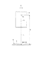
図1は、有線式の計測ヘッドを有する被加工物計測装置が設けられた工作機械の斜視図、図2は、図1に示す被加工物計測装置の概略構成図、図3は被加工物計測状態を示す説明図、図4は、制御装置に入力したデータと算出結果とを示す表である。
(First embodiment)
Hereinafter, a first embodiment of the present invention will be described with reference to FIGS.
1 is a perspective view of a machine tool provided with a workpiece measuring device having a wired measuring head, FIG. 2 is a schematic configuration diagram of the workpiece measuring device shown in FIG. 1, and FIG. 3 is a workpiece. FIG. 4 is an explanatory diagram showing a measurement state, and FIG. 4 is a table showing data input to the control device and calculation results.
図1,図2に示すように、本実施例では、工作機械1として立形マシニングセンタを示している。工作機械1は、床面上に据え付けられたベッド2と、ベッド2上に設置されたコラム3と、主軸4を有する主軸頭5と、テーブル6を有するサドル7とを備えている。工作機械1は、NC装置(数値制御装置)13により制御されている。
主軸頭5は、コラム3の前面に支持されて、上下方向(Z軸方向)に移動可能になっている。主軸4の先端には、工具18が着脱可能に装着される。主軸4は、その中心軸線がZ軸と平行で且つ中心軸線まわりに回転可能に、主軸頭5に支持されている。
As shown in FIGS. 1 and 2, in this embodiment, a vertical machining center is shown as the
The
サドル7は、ベッド2上に配置されて前後の水平方向(Y軸方向)に移動可能である。サドル7上にはテーブル6が配置されている。テーブル6は、左右の水平方向(X軸方向)に移動可能である。テーブル6上には被加工物9が載置されている。互いに直交する移動軸(X軸,Y軸およびZ軸)により、直交3軸が構成されている。
コラム3に支持されている主軸頭5は、Z軸送り機構10に駆動されてZ軸方向に移動する。ベッド2上に配置されているサドル7は、Y軸送り機構11に駆動されてY軸方向に移動する。サドル7上に載置されて被加工物9を支持するテーブル6は、X軸送り機構12に駆動されてX軸方向に移動する。
このように、主軸頭5,主軸4,サドル7,テーブル6などは、送り機構10,11,12に駆動されて各軸方向に移動可能な移動体である。
The
The
As described above, the
NC装置13は、X軸送り機構12,Y軸送り機構11およびZ軸送り機構10をそれぞれ制御する。また、NC装置13は、主軸4に対して工具18を自動的に交換するATC(自動工具交換装置)14を制御する。
したがって、工作機械1は、主軸4と被加工物9を、相対的にX軸,Y軸,Z軸の直交3軸方向に直線移動させる3軸制御を行うマシニングセンタである。なお、主軸頭5と被加工物9を、相対的にX軸,Y軸方向にそれぞれ移動させる場合であってもよい。
The
Therefore, the
工作機械1は、X軸用スケール43,Y軸用スケール44,Z軸用スケール45を含む位置検出装置30を有している。
X軸用スケール43は、移動体のX軸方向の現在位置を検出して、フィードバック信号KxをNC装置13に出力する。Y軸用スケール44は、移動体のY軸方向の現在位置を検出して、フィードバック信号KyをNC装置13に出力する。Z軸用スケール45は、移動体のZ軸方向の現在位置を検出して、フィードバック信号KzをNC装置13に出力する。
NC装置13は、位置検出装置30から出力されたフィードバック信号Kx,Ky,Kzに基づいて、X軸送り機構12,Y軸送り機構11およびZ軸送り機構10をそれぞれ制御して、移動体の直交3軸方向の現在位置が正しい位置になるように調整している。
The
The
The
図1ないし図3に示すように、被加工物計測装置20は、有線式の計測ヘッド8と、被加工物計測装置20を制御する制御装置(たとえば、パーソナルコンピュータ、マイクロコンピュータ)23と、NC装置13の外部に別途独立して設けられた外部モジュール29とを備えている。
As shown in FIGS. 1 to 3, the
計測ヘッド8は、NC装置13により制御される工作機械1の加工領域内で、被加工物9に対して相対的に移動する移動体(ここでは、主軸頭5)に取付けられて、被加工物9の位置および形状を検出する。計測ヘッド8は、被加工物9との距離を計測して距離データB1を出力することが可能な変位センサーである。
被加工物計測装置20およびこれを使用した被加工物計測方法は、主軸頭5に取付けられた計測ヘッド8により、被加工物9を非接触で(または、接触して)計測可能である。
計測ヘッド8が取付けられている移動体の1軸以上の移動軸の位置データC1を取得するインターフェース(外部モジュール29)が、NC装置13の外に設けられている。計測ヘッド8による距離計測と同じ時間間隔ΔTで、移動体に取付けられている計測ヘッド8の位置データC1を取得することが可能なように構成されている。
得られた距離計測データB1と計測ヘッド8の位置データC1から、被加工物9の位置を計算により求めている。そして、計測ヘッド8を移動させながら連続計測を行うことにより、被加工物9の連続形状を計測することができる。
The measuring
The
An interface (external module 29) for obtaining position data C1 of one or more moving axes of the moving body to which the measuring
From the obtained distance measurement data B1 and position data C1 of the
主軸頭5の前面5aには、計測ヘッド8を収納するための筐体19が取付けられている。筐体19は計測ヘッド8を出退可能に支持している。計測ヘッド8は、その使用時には筐体19から下方に突出し、非使用時には筐体19の内部に収納される。計測ヘッド8は、筐体19から下方に露出した状態で被加工物9を計測する。なお、計測ヘッド8を支持する筐体19を、主軸頭5の側面や下面に設けてもよい。
A
外部モジュール29は、デジタルシグナルプロセッサ,FPGA(Field Programmable Gate Array),マイクロコンピュータおよびパーソナルコンピュータからなる群から選択される。
外部モジュール29は、被加工物9上の被計測点Sに対する計測ヘッド8の位置のデータが、各軸方向(X軸方向,Y軸方向,Z軸方向)の位置検出装置30からフィードバックされるとき、フィードバック信号Kx,Ky,Kzを一定の時間間隔ΔT毎に読み取って取得する。
本実施例では、計測ヘッド8の位置データC1は、第1の軸方向(Z軸方向)と、計測ヘッド8が走査する第2の軸方向(X軸方向)とを含む、少なくとも2軸方向(Z軸方向、X軸方向)の位置のデータである。この「2軸方向の位置」は、互いに直交するZ軸方向とX軸方向の位置の場合が多いが、2軸が直交していない場合でもよい。
外部モジュール29は、フィードバック信号Kx,Ky,Kzを、一定の時間間隔ΔT毎に読み取って、フィードバック信号Kx,Ky,Kzから計測ヘッド8の直交3軸方向の位置データC1(X,Y,Z)を取得する。
The
The
In this embodiment, the position data C1 of the measuring
The
計測ヘッド8の位置データC1は、位置検出装置30からNC装置13にフィードバックされている。外部モジュール29は、位置検出装置30からNC装置13にフィードバックされるフィードバック信号Kx,Ky,Kzを、分岐して取得している。
なお、計測ヘッド8の位置データC1は、位置検出装置30から外部モジュール29を介してNC装置13にフィードバックしてもよい。この場合、フィードバック信号Kx,Ky,Kzは、位置検出装置30から外部モジュール29を介してNC装置13に送られる。
なお、位置検出装置30は、スケール43,44,45の代わりに、サーボモータの回転角度に基づいて移動体の現在位置を検出してフィードバック信号Kx,Ky,Kzを出力する「エンコーダ」を含む場合でもよい。この場合、計測ヘッド8が取付けられた移動軸の位置データC1は、NC装置13が使用しているモータエンコーダー信号を分岐したデータである。
The
The position data C1 of the measuring
The
被加工物計測装置20は、外部モジュール29に設けられたパルス出力部24を有している。パルス出力部24は、同期信号(トリガー)となるタイミングパルスPを、計測ヘッド8および位置検出装置30の一方または両方に(本実施例では、計測ヘッド8と位置検出装置30の両方に)出力する。
パルス出力部24は、一定の時間間隔ΔTに対応するパルス間隔(一つのパルスから、次のパルスまでの時間間隔)を有するタイミングパルスPを出力する。タイミングパルスPは、「タイミングをとるためのパルス」であり、本実施例では、計測ヘッド8による計測の動作と、位置検出装置30による現在位置の検出の動作との、タイミングを合わせるのに使用される。
The
The
工作機械1を制御するプログラマブルコントローラ(以下、コントローラと記載)25は、たとえば、PMC(プログラマブル・マシン・コントローラ)やPLC(プログラマブル・ロジック・コントローラ)などである。
図示するコントローラ25は、NC装置13に含まれている。なお、コントローラ25の構成自体が、NC装置13とは分離した構成であってもよい。
A programmable controller (hereinafter referred to as a controller) 25 that controls the
The illustrated
ところで、もし仮に、コントローラ25にクロックとパルス出力部を設けた場合、このクロックは、規則的な信号を一定の時間間隔ΔT毎に出力する。コントローラ25は、クロックの信号に従って、計測ヘッド8の位置データをNC装置13から読み取って取得することになる。
この場合、コントローラ25のクロックから出力される信号の一定の時間間隔ΔTは、たとえば16[msec(ミリ秒)]が限界であり、これ以下の値にすることは現時点では困難である。
その結果、タイミングパルスPのパルス間隔も基本的には16[msec]となり、パルス間隔と前記一定の時間間隔ΔTとが、同じになる。したがって、計測ヘッド8も、16[msec]の時間間隔毎にしか計測できないことになる。
By the way, if a clock and a pulse output unit are provided in the
In this case, the constant time interval ΔT of the signal output from the clock of the
As a result, the pulse interval of the timing pulse P is basically 16 [msec], and the pulse interval and the constant time interval ΔT are the same. Therefore, the measuring
これに対して、本実施例では、パルス出力部24を外部モジュール29に設けているので、パルスの間隔を自在に短く設定することができる。したがって、パルス出力部24は、一定の時間間隔ΔTに対応するパルス間隔(たとえば、1[msec])を有するタイミングパルスPを出力することができる。
その結果、計測ヘッド8は、極めて短い時間間隔ΔT(1[msec])毎に被加工物9を計測できる。よって、計測ヘッド8の位置データC1をNC装置13から取得する際の時間の制限を受けず、計測ヘッド8を高速で走査させて、短時間で被加工物9の2次元形状または3次元形状の計測を行なって、計測後の加工動作に速やかに移行することができる。また、計測ヘッド8は、短時間で被加工物9の広い範囲を計測することができる。
On the other hand, in this embodiment, since the
As a result, the measuring
外部モジュール29から出力されパルス出力部24のタイミングパルスPを含む計測指令fの信号Fは、配線60を介して、主軸頭5に取付けられた計測ヘッド8に送られる。計測ヘッド8で計測された被加工物9に対する距離のデータB1は、配線61を介して外部モジュール29に送られる。
A signal F of the measurement command f output from the
被加工物計測装置20で被加工物9を計測する場合、外部モジュール29が、位置検出装置30からフィードバックされるフィードバック信号Kx,Ky,Kzから、計測ヘッド8の位置データC1を読み取って取得する。
本実施例の外部モジュール29は、被加工物9上の被計測点Sに対する計測ヘッド8の直交3軸方向(X軸方向,Y軸方向,Z軸方向)の位置のデータC1を取得する。「計測ヘッド8の位置」は、計測ヘッド8においてあらかじめ決められた基準位置S1のことであり、たとえば、レーザ発振器におけるレーザ光Lの出口部の位置である。
When measuring the
The
そして、パルス出力部24がタイミングパルスPを出力すると、外部モジュール29は、計測指令fを含む信号Fを、計測ヘッド8に配線60を介して出力する。その結果、外部モジュール29が計測ヘッド8の位置データC1を取得する動作のタイミングと同じタイミングで、計測ヘッド8が計測指令fに従って被加工物9を計測する。
こうして計測ヘッド8は、計測ヘッド8から被加工物9までの距離Dを計測する。計測されたデータB1は、計測ヘッド8から配線61で外部モジュール29に出力される。
When the
Thus, the measuring
このようにして、外部モジュール29による計測ヘッド8の位置データC1の取得の動作と、その時点における計測ヘッド8による被加工物9の計測の動作とを、常に同一のタイミングで(すなわち、同時に)、一定の時間間隔ΔT(1[msec])毎に繰り返して行なっている。
すなわち、外部モジュール29は、被加工物9上の被計測点Sに対する計測ヘッド8の少なくとも2軸方向(Z軸方向、X軸方向)の位置データC1を、位置検出装置30からフィードバックされるフィードバック信号Kx,Ky,Kzから読み取って取得する。
この外部モジュール29の動作と同時に、且つ一定の時間間隔ΔT(1[msec])毎に、計測ヘッド8は、その時点における計測ヘッド8から被加工物9までの距離Dを計測する。
In this way, the operation of acquiring the position data C1 of the measuring
That is, the
Simultaneously with the operation of the
外部モジュール29により取得された計測ヘッド8の位置データC1は、制御装置23に出力して格納される。計測指令fにより計測ヘッド8で計測された被加工物9に対する距離のデータB1は、外部モジュール29に一旦出力してここで記憶した後、制御装置23に出力して格納される。なお、距離データB1は、計測ヘッド8から直接制御装置23に出力されてもよい。
制御装置23は、位置データC1と距離データB1とに基づいて演算を行うことにより、被加工物9の2次元形状データまたは3次元形状データを得る。
The position data C1 of the measuring
The
上述の構成の被加工物計測装置20およびこの装置20による被加工物計測方法によれば、NC装置13やコントローラ25に対して新たな機能を付加するなどの改造や変更をする必要がない。
また、NC装置13やコントローラ25の制約事項に規制されずに、独自に被加工物計測装置20を設計,製造できる。その結果、どのような構成のNC装置13やコントローラ25を有する工作機械1であっても、被加工物計測装置20を適用することができる。
被加工物9上の被計測点Sに対する計測ヘッド8の少なくとも2軸方向(Z軸方向、X軸方向)の位置データC1の取得の動作と、その時点における計測ヘッド8による被加工物9の計測の動作とを、きわめて短い時間間隔ΔT(1[msec])毎に繰り返して行なっている。
その結果、位置データC1と距離データB1を処理することにより、被加工物9の2次元形状または3次元形状の計測を行うことができる。また、計測ヘッド8は高速で走査できることになり、被加工物9が短時間で高精度に計測されて、計測後の加工動作に速やかに移行することができる。
被加工物計測装置20では、外部モジュール29と制御装置23を、NC装置13やコントローラ25とは分離している。したがって、NC装置13やコントローラ25の設計基準や構成などに拘束されることなく、被加工物計測装置20の設計やその変更を、独自に且つ自在に行うことができる。
NC装置13から計測ヘッド8の位置データC1を取得する動作は、NC装置13の本来の役割である工作機械1に対する動作制御の合間に行われる。本発明では、外部モジュール29を設けたので、正確なタイミングで計測ヘッド8の位置データC1を取得することができる。また、位置データC1の取得の時間間隔ΔTを短くして、高速で大量の距離データB1を計測ヘッド8から取得することもできる。したがって、短時間で被加工物9の広い範囲を計測することができる。
According to the
Further, the
An operation of acquiring position data C1 in at least two axial directions (Z-axis direction and X-axis direction) of the
As a result, it is possible to measure the two-dimensional shape or the three-dimensional shape of the
In the
The operation of acquiring the position data C1 of the measuring
外部モジュール29は、位置データ一時記憶部31と距離データ一時記憶部32を有している。記憶部31,32は、移動体の各軸方向の位置検出装置30から出力される移動軸の位置データC1と、計測ヘッド8により計測された距離データB1を、同時刻毎に関連づけて記憶するメモリーである。記憶部31,32は、リング状のバッファメモリが好ましいが、その他のメモリであってもよい。
外部モジュール29は、パルス出力部24から一定の時間間隔ΔT(1[msec])毎に出力されるタイミングパルスPのタイミングで、位置検出装置30からフィードバックされるフィードバック信号Kx,Ky,Kzから、計測ヘッド8の位置データC1を取得する。その後、この位置データC1は制御装置23に送られる。
The
From the feedback signals Kx, Ky, Kz fed back from the
すなわち、外部モジュール29は、位置データC1を位置データ一時記憶部31に一時的に記憶させる。その後、位置データC1は、制御装置23の位置データ記憶部26に出力されて格納される。
外部モジュール29は、最新番地カウンタ38の指令により、一定の時間間隔ΔT(1[msec])毎にフィードバック信号Kx,Ky,Kzを読み取って、計測ヘッド8の位置データC1[直交3軸方向(X軸方向,Y軸方向,Z軸方向)の位置データC1]を取得する。すると、位置データ一時記憶部31は、この位置データC1を一時的に記憶する。
That is, the
The
X軸用スケール43から出力されたフィードバック信号Kxに含まれる、移動体のX軸方向の現在位置情報(座標)53は、NC装置13の駆動部56に入力する。Y軸用スケール44から出力されたフィードバック信号Kyに含まれる、移動体のY軸方向の現在位置情報(座標)54と、Z軸用スケール45から出力されたフィードバック信号Kzに含まれる、移動体のZ軸方向の現在位置情報(座標)55も、それぞれNC装置13の駆動部56に入力する。
駆動部56は、フィードバック信号Kx,Ky,Kzにそれぞれ含まれる現在位置情報53,54,55に基づいて、X軸送り機構12,Y軸送り機構11およびZ軸送り機構10を、それぞれ駆動する。
The current position information (coordinates) 53 in the X-axis direction of the moving body included in the feedback signal Kx output from the
The
各軸方向(X軸方向,Y軸方向,Z軸方向)の位置検出装置30は、計測ヘッド8の位置データC1を含むフィードバック信号Kx,Ky,Kzをフィードバックして、外部モジュール29の位置データ一時記憶部31に出力する。位置データ一時記憶部31は、フィードバック信号Kx,Ky,Kzに含まれる位置データC1を一時的に記憶する。位置データ一時記憶部31に記憶された位置データC1は、その後、制御装置23に出力されて格納される。
計測ヘッド8で計測された距離データB1は、外部モジュール29の距離データ一時記憶部32に出力されて一時的に記憶された後、制御装置23に出力されて格納される。
The
The distance data B1 measured by the measuring
上述のように、外部モジュール29は、一定の時間間隔ΔT(1[msec])毎にフィードバック信号Kx,Ky,Kzを読み取って、計測ヘッド8の位置データC1を取得する。すると、この位置データC1は、位置データ一時記憶部31に一時的に記憶された後、外部モジュール29から制御装置23に出力される。
計測ヘッド8が被加工物9を計測すると、計測ヘッド8から外部モジュール29に距離データB1が出力される。この距離データB1は、外部モジュール29の距離データ一時記憶部32に一時的に記憶された後、外部モジュール29から制御装置23に出力される。
As described above, the
When the measuring
たとえば、被加工物9上の1番目の被計測点Sを計測したときの計測ヘッド8のX軸方向,Y軸方向,Z軸方向のそれぞれの現在位置情報を、外部モジュール29が、フィードバック信号Kx,Ky,Kzから読み取る。すると、位置データ一時記憶部31の番地「1」に、座標値「X1,Y1,Z1」が書き込まれる。
次いで、被加工物9上の2番目の被計測点Sを計測したときの計測ヘッド8のX軸方向,Y軸方向,Z軸方向のそれぞれの現在位置情報を、外部モジュール29が、フィードバック信号Kx,Ky,Kzから読み取る。すると、位置データ一時記憶部31の番地「2」に、次の座標値「X2,Y2,Z2」が書き込まれる。
以下同様にして、被加工物9上のN番目の被計測点Sを計測したときの計測ヘッド8のX軸方向,Y軸方向,Z軸方向のそれぞれの現在位置情報を、外部モジュール29が、フィードバック信号Kx,Ky,Kzから読み取る。すると、位置データ一時記憶部31の番地「N」に、座標値「Xn,Yn,Zn」が書き込まれる。
For example, the
Next, the
Similarly, the
このようにして、計測ヘッド8の1番目からN番目までのN個の位置データC1が、位置データ一時記憶部31に順番に一時的に記憶される。その後、N個または所定の個数の位置データC1は、制御装置23の位置データ記憶部26に同時に格納される。
なお、位置データ一時記憶部31を、外部モジュール29の外部に別途設けてもよい。また、位置データ一時記憶部31は、NC装置13またはコントローラ25の各内部に設けられているメモリを流用することもできる。
In this way, the first to Nth position data C1 of the measuring
The position data
他方たとえば、計測ヘッド8が、被加工物9上の1番目の被計測点Sを計測したとき、計測ヘッド8は、その時点における計測ヘッド8から被加工物9までの距離D1を計測する。すると、外部モジュール29がこの距離データを読み取って、距離データ一時記憶部32の番地「1」に、距離「D1」が書き込まれる。
次いで、計測ヘッド8が、被加工物9上の2番目の被計測点Sを計測したとき、計測ヘッド8は、その時点における計測ヘッド8から被加工物9までの距離D2を計測する。すると、外部モジュール29がこの距離データを読み取って、距離データ一時記憶部32の番地「2」に、距離「D2」が書き込まれる。
以下同様にして、計測ヘッド8が、被加工物9上のN番目の被計測点Sを計測したとき、計測ヘッド8は、その時点における計測ヘッド8から被加工物9までの距離Dnを計測する。すると、外部モジュール29がこの距離データを読み取って、距離データ一時記憶部32の番地「N」に、距離「Dn」が書き込まれる。
On the other hand, for example, when the
Next, when the
Similarly, when the
このようにして、計測ヘッド8の1番目からN番目までのN個の距離データB1が、距離データ一時記憶部32に順番に一時的に記憶される。その後、N個または所定の個数の距離データB1は、制御装置23の距離データ記憶部21に同時に格納される。
なお、距離データ一時記憶部32を、外部モジュール29の外部に別途設けてもよい。また、距離データ一時記憶部32は、NC装置13またはコントローラ25の各内部に設けられているメモリを流用することもできる。
In this way, the N distance data B1 from the first to the Nth of the measuring
The distance data
制御装置23は、位置データC1を格納する位置データ記憶部26と、距離データB1を格納する距離データ記憶部21と、演算処理部27とを有している。
記憶部26,21は、移動体の各軸方向の位置検出装置30から出力される移動軸の位置データC1と、計測ヘッド8により計測された距離データB1を、同時刻毎に関連づけて記憶するメモリーである。
計測ヘッド8における少なくとも2軸方向の位置データC1は、外部モジュール29で取得されて位置データ一時記憶部31に一時的に記憶された後、制御装置23の位置データ記憶部26に格納される。
すなわち、外部モジュール29の位置データ一時記憶部31に記憶されている位置データC1は、位置データ記憶部26に格納される。このとき、位置データ記憶部26は、制御装置23に設けられている開始番地メモリ(カウンタ)37から出力される指令と、外部モジュール29に設けられている最新番地カウンタ38の指令とに従って、位置データC1を順次読み出すとともにこうして読み出された位置データC1を格納する。なお、2つの記憶部21,26を、制御装置23とは分離して別途設けてもよい。
The
The
Position data C1 in at least two axial directions in the measuring
That is, the
被加工物9の距離データB1は、計測指令fにより計測ヘッド8で計測され、配線61を介して外部モジュール29に出力されて、距離データ一時記憶部32に一時的に記憶される。その後、距離データB1は、制御装置23の距離データ記憶部21に格納される。すなわち、制御装置23は、外部モジュール29から送られてきた距離データB1を、距離データ記憶部21に順次格納する。
演算処理部27は、計測ヘッド8で計測された距離Dのデータ(すなわち、距離データB1)と、外部モジュール29で取得された少なくとも2軸方向(Z軸方向,X軸方向)の位置のデータ(計測ヘッド8の位置を示すデータC1)とに基づいて、演算を行う。
すなわち、演算処理部27は、位置データ記憶部26に格納されている位置データC1と、距離データ記憶部21に格納されている距離データB1とに基づいて、演算を行う。これにより、被加工物9の2次元形状または3次元形状のデータが得られる。
The distance data B1 of the
The
That is, the
工具18は工具マガジンに収納可能である。NC装置13で制御されるATC14により、工具18は、主軸4に対して自動的に交換されるとともに着脱可能である。したがって、主軸4に装着された工具18で被加工物9を加工する工程の前に(または、加工工程の途中に、もしくは加工工程後に)、計測ヘッド8で被加工物9を計測する工程を設ければ、加工動作と計測動作とが順番にまたはこれとは逆の順に連続する。すなわち、加工動作と計測動作とを、任意の組合せで実行することが可能である。
このようにすれば、計測のために被加工物9をテーブル6から取り外さなくても、被加工物9を加工したのちテーブル6に取付けたままで直ちに、被加工物9の2次元形状または3次元形状の計測ができる。また、被加工物9を計測した動作の後に、再び被加工物9を加工する動作に移行することもできる。
The
In this way, even if the
本発明の関連技術として、計測ヘッド8を主軸4に着脱可能に装着する場合がある。ところが、主軸4に対して計測ヘッド8を着脱すると、着脱の前後で計測ヘッド8での計測に誤差が生じる恐れがある。また、主軸4に対して工具18を着脱すると、着脱の前後で工具18での加工に誤差が生じる恐れがある。
これに対して本実施例では、計測ヘッド8は、主軸頭5に取付けられており、主軸4には装着されないようになっている。したがって、工具18を取外すことなく主軸4に装着したままで、計測ヘッド8で被加工物9を高精度に計測できる。また、工具18で被加工物9を高精度に加工することができる。
計測ヘッド8は、移動体(ここでは、主軸頭5)の主軸4に装着されている状態の工具18の近傍に配置されている。これにより、計測ヘッド8は、工具18に近い位置で被加工物9を高精度に計測できる。
なお、計測ヘッド8が取付けられる移動体は、マシニングセンタの主軸頭5のほかに、テーブル6、サドル7、旋盤の刃物台やタレット、複合加工機における揺動可能な工具用主軸であってもよい。
As a related technique of the present invention, the
On the other hand, in this embodiment, the measuring
The measuring
In addition to the
計測ヘッド8は、被加工物9の表面に照射するためのレーザ光Lを発生させるレーザ発振器を内蔵している。レーザ発振器で発生したレーザ光Lは、被加工物9の表面の被計測点Sに照射される。計測ヘッド8は、被加工物9の表面で反射したレーザ光Lを受光することにより、計測ヘッド8から被加工物9までの距離Dを算出する。
この距離Dは、計測ヘッド8の基準位置S1と被加工物9上の被計測点Sとの間の、基準軸線CL(たとえば、計測ヘッド8から射出されるレーザ光Lの中心軸線CL)の方向(すなわち、Z軸方向)における距離である。
計測指令fの信号Fは、パルス出力部24から計測ヘッド8に有線(配線60)で送られる。計測ヘッド8は、計測指令fを受けるとレーザ発振器によりレーザ光Lを発生し、このレーザ光Lを被加工物9に照射する。
被加工物9上の被計測点Sでレーザ光Lが反射するので、この反射したレーザ光Lに基づいて、計測ヘッド8から被加工物9までの距離Dが算出される。算出された距離Dなどを含む距離データB1は、配線61で外部モジュール29に出力される。
The measuring
This distance D is a reference axis line CL (for example, the central axis line CL of the laser beam L emitted from the measurement head 8) between the reference position S1 of the
The signal F of the measurement command f is sent from the
Since the laser beam L is reflected at the measurement point S on the
このように、計測ヘッド8は、計測指令fを受けると、計測ヘッド8から被加工物9までの距離Dを計測することにより、この被加工物9を非接触で計測する。
計測動作の際に、計測ヘッド8は被加工物9に接触しないので、計測ヘッド8を高速で安全に且つ振動なし(または、低振動)で走査して、短時間で被加工物9の広い範囲を計測することができる。
As described above, when the
Since the measuring
次に、被加工物計測装置20で被加工物9を計測する手順について説明する。
まず最初に、計測用プログラムで計測ヘッド8を呼び出す。そして、主軸頭5を移動させて、主軸頭5に取付けられている計測ヘッド8を、計測(スキャン)の開始点に位置決めする。
次いで、計測用プログラム中のMコード指令により、NC装置13,外部モジュール29,制御装置23などを計測準備状態にする。計測用プログラムの移動指令により、計測ヘッド8が被加工物9の上方で移動を開始する。
Next, a procedure for measuring the
First, the
Next, the
NC装置13が計測開始の指令gを外部モジュール29に出力すると、外部モジュール29は、パルス出力部24から一定の時間間隔ΔT(1[msec])毎に出力されるタイミングパルスPに従って、位置検出装置30から出力されるフィードバック信号Kx,Ky,Kzから計測ヘッド8の位置データC1を読み取って取得する。
この位置データC1は、被加工物9上の被計測点Sに対する計測ヘッド8の直交3軸方向(X軸方向,Y軸方向,Z軸方向)の現在位置情報(座標)である。位置データC1は、外部モジュール29の位置データ一時記憶部31に、順次一時的に記憶される。
When the
The position data C1 is current position information (coordinates) in the three orthogonal directions (X-axis direction, Y-axis direction, and Z-axis direction) of the measuring
外部モジュール29がこの読み取り動作(取得動作)を行い、パルス出力部24のタイミングパルスPに基づいて、外部モジュール29から計測ヘッド8に計測指令fの信号Fが送信される。
計測ヘッド8は、計測指令fを受信すると、計測ヘッド8から被加工物9までの距離Dを計測する。計測ヘッド8から出力される距離データB1は、配線61を介して外部モジュール29に出力されて距離データ一時記憶部32に一時的に記憶される。その後、この距離データB1は、制御装置23の距離データ記憶部21に出力される。
The
When receiving the measurement command f, the
外部モジュール29が、フィードバック信号Kx,Ky,Kzから計測ヘッド8の位置データC1を読み取って位置データ一時記憶部31に一つ追加記憶させる毎に、外部モジュール29の最新番地カウンタ38の数値を一つ加算する。
最後に書き込んだ番地を、位置データ一時記憶部31に保持する。その後、外部モジュール29は、この位置データC1を制御装置23の位置データ記憶部26に出力する。
Each time the
The address written last is held in the position data
制御装置23は、位置データ一時記憶部31に記憶された一連の位置データC1を順次読み取って、位置データ記憶部26に順次保管する。このとき、位置データ一時記憶部31内で読み取るべき一連の位置データの先頭番地を、制御装置23の開始番地メモリ37で保持しておき、位置データを読み取る毎に、開始番地メモリ37の値を更新しておく。
読み取るべき一連の位置データの最終番地は、外部モジュール29の最新番地カウンタ38により示されている。
The
The final address of a series of position data to be read is indicated by the
プログラム中のMコードの指令が出力されると、制御装置23は、外部モジュール29に計測終了の指令を出力する。すると、被加工物計測装置20による計測が終了し、パルス出力部24は、タイミングパルスPのパルス信号の出力を終了する。この出力の終了時に、位置検出装置30または計測ヘッド8が、一定の時間ΔT(1[msec])後にパルス信号を受け取らなければ、計測終了と判断される。
そして、制御装置23内で位置データ記憶部26に保管された一連の位置データC1のうち1個目の位置データ(X0,Y0,Z0)を削除する。これは、計測開始時に、最初の位置データに相当する距離データは存在しないからである。
また、距離データB1のうち最後の1個の距離データを削除する。これは、最後の距離データに相当する位置データは存在しないからである。
次いで、演算処理部27は、それぞれの時点における位置データ[(X1,Y1,Z1),(X2,Y2,Z2),(X3,Y3,Z3),……,(Xn,Yn,Zn),……]と距離データ(D1,D2,D3,……,Dn,……)とを合わせて、被加工物9の2次元形状データまたは3次元形状データを算出する。
When the M code command in the program is output, the
Then, the first position data (X0, Y0, Z0) is deleted from the series of position data C1 stored in the position
Further, the last one piece of distance data is deleted from the distance data B1. This is because there is no position data corresponding to the last distance data.
Next, the
本発明では、制御装置23は必要最小限の距離データB1を処理すればよい。したがって、データ処理の負荷は小さくなり、位置データ一時記憶部31,距離データ一時記憶部32,位置データ記憶部26および距離データ記憶部21の各メモリ容量も小さくて済む。
外部モジュール29に位置データ一時記憶部31を設けたので、計測ヘッド8の直交3軸方向(X軸方向,Y軸方向,Z軸方向)の位置データC1を、位置データ一時記憶部31に一時的に記憶することができる。
その後、制御装置23の開始番地メモリ37から出力される指令と、外部モジュール29の最新番地カウンタ38の指令とに従って、位置データC1を複数個まとめて位置データ記憶部26に順次格納することができる。したがって、外部モジュール29,位置データ一時記憶部31および制御装置23が位置データC1を処理するための負担は小さくてすむ。
In the present invention, the
Since the position data
Thereafter, a plurality of position data C1 can be collectively stored in the position
演算処理部27は、距離データ記憶部21に格納されている距離データB1と、位置データ記憶部26に格納されている計測ヘッド8の直交3軸方向の位置データC1とに基づいて、演算を行う。これにより、被加工物9の2次元形状データまたは3次元形状データが得られる。
こうして、被加工物9上の多数の被計測点Sの各座標のデータ(2次元形状データまたは3次元形状データ)が算出される。この多数の被計測点Sの各座標のデータは、制御装置23とは別に設けられた演算装置(たとえば、パーソナルコンピュータ)28に出力される。
演算装置28は、多数の被計測点Sの座標を集合させる演算を行うことにより、被加工物9の立体図すなわち3次元形状E(図3)が得られる。
The
In this way, data (two-dimensional shape data or three-dimensional shape data) of each coordinate of a large number of measurement points S on the
The
図4は、制御装置23に入力した計測距離DのデータB1と、直交3軸方向の位置データC1と、これら計測距離DのデータB1および位置データC1に基づいて算出された結果とを示している。この算出結果は、3次元形状データ(すなわち、被加工物9上の被計測点Sの座標)である。
FIG. 4 shows the data B1 of the measurement distance D input to the
上述の説明では、パルス出力部24が、タイミングパルスPを1[msec]のパルス間隔で出力する場合を示している。このタイミングパルスPは、データ取得のタイミングを確認するために使用されるので、パルス間隔および計測の間隔は、制限はなく任意の値でよい。
In the above description, the
被加工物計測装置20による計測の終了について、予め設定されているパルス間隔(1[msec])で、計測ヘッド8と位置検出装置30にタイミングパルスPのパルス信号が入力しなければ、計測終了と判断される。
ところで、この判定方法の場合、パルス間隔が長い値(たとえば160[msec])であると仮定する。この場合、外部モジュール29が、制御装置23から計測終了の指令を受信しても、計測ヘッド8が、160[msec]の長い時間後にタイミングパルスPが来ないことを認識するまで、計測ヘッド8は、被加工物9を計測して距離データB1を出力し続ける。その結果、計測終了直前に、外部モジュール29でせっかく取得した距離データB1が、無駄になってしまう。
そこで、NC装置13は、計測終了の指令gを外部モジュール29に送信し、この外部モジュール29が指令gを受信すると計測ヘッド8は計測を終了する構成にしている。このようにすれば、計測終了直前に外部モジュール29が不要なデータを取得して無駄が発生するといった不具合がなくなる。
Regarding the end of the measurement by the
By the way, in this determination method, it is assumed that the pulse interval is a long value (for example, 160 [msec]). In this case, even if the
Therefore, the
第1実施例の変形例として、有線式の計測ヘッド8を、工作機械1の主軸4に着脱可能に装着する場合がある。この場合、被加工物9を計測する際には、ATC14で主軸4から工具18を取外した後、オペレータが、手動で計測ヘッド8を主軸4に対して装着したり取外したりすることになる。
こうすれば、既設の工作機械であっても、本発明の被加工物計測装置20を適用することができる。
As a modification of the first embodiment, there is a case where the
By doing so, the
(第2実施例)
図5は、本発明の第2実施例にかかる無線式の計測ヘッド8aを有する工作機械101における被加工物計測装置20aの概略構成図である。第1実施例と同一または相当部分には同一符号を付してその説明を省略する。
図5に示すように、被加工物計測装置20aは、被加工物9を計測する無線式の計測ヘッド8aを有している。計測ヘッド8aは、NC装置13により制御される工作機械101の加工領域内で、被加工物9に対して相対的に移動する移動体としての主軸頭5に取付けられて、被加工物9の位置および形状を検出する。計測ヘッド8aは、被加工物9との距離Dを計測して距離データB1を出力することが可能な変位センサーである。
被加工物計測装置20aは、被加工物計測装置20aを制御する制御装置23と、外部モジュール29とを有している。
計測ヘッド8aが取付けられている主軸頭5の1軸以上の移動軸の位置データC1を取得する外部モジュール29が、NC装置13の外に設けられている。計測ヘッド8aによる距離計測と同じ時間間隔ΔTで、主軸頭5に取付けられている計測ヘッド8aの位置データC1を取得することが可能なように構成されている。
得られた距離計測データB1と計測ヘッド8aの位置データC1から、被加工物9の位置を計算により求めている。そして、計測ヘッド8aを移動させながら連続計測を行うことにより、被加工物9の連続形状を計測することができる。
(Second embodiment)
FIG. 5 is a schematic configuration diagram of the
As shown in FIG. 5, the
The
An
From the obtained distance measurement data B1 and position data C1 of the
外部モジュール29は、NC装置13とは別途に設けられている。外部モジュール29は、被加工物9上の被計測点に対する計測ヘッド8aの、第1の軸方向(Z軸方向)とこの計測ヘッド8aが走査する第2の軸方向(X軸方向)とを含む少なくとも2軸方向の位置のデータC1が、各軸方向の位置検出装置30からフィードバックされるとき、フィードバック信号Kx,Ky,Kzを一定の時間間隔ΔT(1[msec])毎に取得する。
被加工物計測装置20aのパルス出力部24は、外部モジュール29に設けられ、タイミングパルスPを、計測ヘッド8aおよび各軸方向の位置検出装置30の一方または両方(本実施例では、両方)に出力する。
The
The
計測ヘッド8aの位置データC1は、位置検出装置30からNC装置13にフィードバックされる。外部モジュール29は、位置検出装置30からNC装置13にフィードバックされるフィードバック信号Kx,Ky,Kzを、分岐して取得している。
The position data C1 of the measuring
被加工物計測装置20aで計測する場合は、計測ヘッド8aが被加工物9を計測すると、外部モジュール29は、位置検出装置30からフィードバックされるフィードバック信号Kx,Ky,Kzから計測ヘッド8aの位置データC1を取得する。外部モジュール29により取得された計測ヘッド8aの位置データC1は、制御装置23に出力されて格納される。
他方、計測ヘッド8aで計測された被加工物9の距離データB1は、制御装置23に出力して格納される。そして、制御装置23は、位置データC1と距離データB1とに基づいて演算を行うことにより、被加工物9の2次元形状データまたは3次元形状データを得る。
上述の構成の被加工物計測装置20aおよびこの装置20aによる被加工物計測方法によれば、第1実施例と同じ作用効果を奏する。
When measuring with the
On the other hand, the distance data B1 of the
According to the
各軸方向の位置検出装置30は、位置データC1のフィードバック信号Kx,Ky,Kzを、外部モジュール29の位置データ一時記憶部31に出力する。位置データ一時記憶部31に一時的に記憶された位置データC1は、制御装置23に出力されて格納される。
計測ヘッド8aで計測された距離データB1は、外部モジュール29の距離データ一時記憶部32に出力されて一時的に記憶された後、制御装置23に出力されて格納される。
The
The distance data B1 measured by the measuring
工作機械101において、主軸4の先端には、工具(図示せず)または計測ヘッド8aが着脱可能に装着される。NC装置13は、主軸4に対して工具と計測ヘッド8aをそれぞれ自動的に交換するATC14を制御する。計測ヘッド8aは、工作機械101の主軸4に対して、ATC14により自動的に交換して装着、離脱される。
したがって、工作機械101は、工具または計測ヘッド8aと、被加工物9とを相対的にX軸,Y軸,Z軸の直交3軸方向に直線移動させる3軸制御を行うマシニングセンタである。この工作機械101において、計測ヘッド8aが無線式である点が第1実施例の工作機械1と異なっているが、これ以外の構成は工作機械1と同じである。
被加工物計測装置20aおよびこれを使用した被加工物計測方法は、工作機械101の主軸4に装着される計測ヘッド8aにより、被加工物9を非接触で(または、接触して)計測可能である。
In the
Therefore, the
The
計測ヘッド8aが無線式なので、被加工物計測装置20aは、主軸4に装着された状態の計測ヘッド8aとの間で無線で送受信を行うための送信受信部22を有している。外部モジュール29に設けられているパルス出力部24は、送信受信部22にタイミングパルスPを出力する。タイミングパルスPは、送信受信部22でタイミングを合わせるのに使用される。
送信受信部22と計測ヘッド8aの間では、計測指令fや距離データなどの信号Fが、無線によって送受信される。送信受信部22は、パルス出力部24からタイミングパルスPを受信すると、タイミングパルスPのタイミングに合わせた計測指令fの信号Fを計測ヘッド8aに送信する。
計測指令fが計測ヘッド8aに入力すると、計測ヘッド8aが、計測ヘッド8aから被加工物9までの距離Dを計測する。計測されたデータを含む信号Fは、計測ヘッド8aから送信受信部22に無線で送信される。送信受信部22は、計測ヘッド8aから受信した距離データB1を、外部モジュール29に送信する。その後、距離データB1は制御装置23に送られる。
Since the
A signal F such as a measurement command f and distance data is transmitted and received between the transmission /
When the measurement command f is input to the
このように本実施例では、計測指令fの信号Fが、送信受信部22から計測ヘッド8aに無線で送信される。計測ヘッド8aは、この計測指令fを受けると、計測ヘッド8aから被加工物9までの距離Dを計測する。
計測動作の際に、計測ヘッド8aは被加工物9に接触しない。したがって、計測ヘッド8aを高速で安全に且つ振動なし(または低振動)で走査して、短時間で被加工物9の広い範囲を計測することができる。
As described above, in this embodiment, the signal F of the measurement command f is wirelessly transmitted from the transmission /
During the measurement operation, the
次に、第1実施例,第2実施例において、本発明の他の変形例を説明する。
上述の各実施例では、制御装置23と外部モジュール29は、分離されている構成が図示されているが、分離しない場合でもよい。
たとえば、制御装置23および外部モジュール29の両方を組み合わせて一緒にする場合や、制御装置23と外部モジュール29のうち、いずれか一方を他方の内部に組み込む場合がある。
Next, another modification of the present invention will be described in the first embodiment and the second embodiment.
In each of the above-described embodiments, the
For example, there are cases where both the
上述の各実施例の外部モジュール29は、位置検出装置30からNC装置13にフィードバックされるフィードバック信号Kx,Ky,Kzを、分岐して取得している。すなわち、フィードバック用の位置検出装置30を被加工物9の計測にも兼用しているが、本発明の位置検出装置30は、被加工物9の計測のみに使用される専用に別途追加された装置でもよい。この場合、計測ヘッド8,8aが取付けられた移動軸の位置データC1は、専用の位置検出装置30から出力されるデータである。
The
この被加工物計測専用の位置検出装置30を有する被加工物計測装置およびその方法について説明する。
この場合の外部モジュール29は、被加工物9上の被計測点Sに対する計測ヘッド8,8aの位置のデータが、各軸方向(X軸方向,Y軸方向,Z軸方向)の位置検出装置30から出力されるとき、出力信号Kx,Ky,Kzを一定の時間間隔ΔT毎に読み取って取得する。
計測ヘッド8,8aの位置データC1は、第1の軸方向(Z軸方向)と、計測ヘッド8,8aが走査する第2の軸方向(X軸方向)とを含む、少なくとも2軸方向(Z軸方向、X軸方向)の位置のデータである。
外部モジュール29は、位置検出装置30から出力される出力信号Kx,Ky,Kzを、一定の時間間隔ΔT毎に読み取って、出力信号Kx,Ky,Kzから計測ヘッド8,8aの直交3軸方向の位置データC1(X,Y,Z)を取得する。
位置検出装置30は、被加工物9の計測のみに使用されるので、NC装置13用の位置検出装置に要求される設計基準や構成などに拘束されることなく、被加工物計測装置20と位置検出装置30の設計やその変更を、独自に且つ自在に行うことができる。
A workpiece measuring apparatus having the
In this case, the
The position data C1 of the measuring heads 8 and 8a includes at least two axial directions including the first axial direction (Z-axis direction) and the second axial direction (X-axis direction) scanned by the measuring heads 8 and 8a ( (Z-axis direction, X-axis direction) position data.
The
Since the
上述の各実施例の工作機械1、101は、主軸4と被加工物9を、相対的にX軸,Y軸,Z軸の直交3軸方向に直線移動させる3軸制御を行うマシニングセンタである。
変形例として、工作機械は、主軸4と被加工物9を、相対的にX軸,Y軸,Z軸の直交3軸方向に直線移動させる3軸制御と、一つまたは複数の旋回軸(B軸,C軸など)を有して相対的に旋回動作可能な制御とを行う、4軸制御や5軸制御の機械であってもよい。
この変形例では、移動体(たとえば、主軸頭5や刃物台)に取付けられる計測ヘッド8,8aは、被加工物9に対して、相対的に直交3軸方向に相対移動可能で、且つ旋回軸まわりに旋回することができる。
そして、被加工物9上の被計測点に対する計測ヘッド8,8aの、第1の軸方向(Z軸方向)とこの計測ヘッド8,8aが走査する第2の軸方向(X軸方向)とを含む少なくとも2軸方向の位置のデータ(この場合は、直交3軸方向と旋回軸まわりの位置データ)が、位置検出装置からフィードバックまたは出力されるとき、外部モジュール29は、フィードバック信号または出力信号を一定の時間間隔ΔT毎に取得する。
そして、外部モジュール29は、位置検出装置からフィードバックまたは出力されるフィードバック信号または出力信号から、計測ヘッド8,8aの位置データを取得する。
The
As a modification, the machine tool has a three-axis control for linearly moving the
In this modification, the measurement heads 8 and 8a attached to the moving body (for example, the
Then, the first axial direction (Z-axis direction) of the measuring heads 8 and 8a with respect to the measurement point on the
Then, the
本発明では、タイミングパルスPがパルス出力部24から位置検出装置30に出力される回路に、遅延回路を設けてもよい。こうすれば、位置検出装置30に入力すべきタイミングパルスPが、遅延回路により、予め設定された時間差だけ積極的に遅れて位置検出装置30に入力する。
これとは逆に、タイミングパルスPがパルス出力部24から計測ヘッド8,8aに出力される回路に、予測システムを設けてもよい。こうすれば、計測ヘッド8,8aに入力すべきタイミングパルスPを含む信号Fが、予測システムにより、予め設定された時間差だけ積極的に早めて計測ヘッドに入力する。
このようにすれば、容易に第1の時間と第2の時間とが一致することになる。第1の時間は、計測ヘッド用のタイミングパルスPの指令により、計測ヘッド8,8aが、被加工物9に対する距離Dを計測する時間である。第2の時間は、位置データ用のタイミングパルスPの指令により、外部モジュール29が、被計測点に対する計測ヘッド8,8aの少なくとも2軸方向の位置を取得する時間である。
In the present invention, a delay circuit may be provided in a circuit in which the timing pulse P is output from the
On the contrary, a prediction system may be provided in a circuit in which the timing pulse P is output from the
In this way, the first time and the second time easily match. The first time is a time during which the measurement heads 8 and 8a measure the distance D with respect to the
以上、本発明の実施例(変形例を含む。以下同じ)を説明したが、本発明は上述の実施例に限定されるものではなく、本発明の要旨の範囲で種々の変形,付加などが可能である。
なお、各図中同一符号は同一または相当部分を示す。
Although the embodiments of the present invention (including modifications, the same applies hereinafter) have been described above, the present invention is not limited to the above-described embodiments, and various modifications and additions can be made within the scope of the present invention. Is possible.
In the drawings, the same reference numerals denote the same or corresponding parts.
本発明にかかる工作機械における被加工物計測装置およびその方法は、マシニングセンタの他に、複合加工機,旋盤,旋削盤,研削盤,レーザ加工機などの工作機械に適用でき、非接触で(または、接触して)被加工物を計測可能である。 The work piece measuring apparatus and method thereof in a machine tool according to the present invention can be applied to machine tools such as a compound processing machine, a lathe, a lathe, a grinder, and a laser processing machine in addition to a machining center. The workpiece can be measured.
1,101 工作機械(立形マシニングセンタ)
5 主軸頭(移動体)
8 有線式の計測ヘッド
8a 無線式の計測ヘッド
9 被加工物
13 NC装置
20,20a 被加工物計測装置
29 外部モジュール
30 位置検出装置
31 位置データ一時記憶部(メモリー)
32 距離データ一時記憶部(メモリー)
B1 距離データ
C1 位置データ
D 距離
X軸 移動軸
Y軸 移動軸
Z軸 移動軸
ΔT 時間間隔
1,101 Machine tool (Vertical machining center)
5 Spindle head (moving body)
8
32 Distance data temporary storage (memory)
B1 Distance data C1 Position data D Distance X axis Movement axis Y axis Movement axis Z axis Movement axis ΔT Time interval
Claims (4)
前記計測ヘッドは、前記被加工物との距離を計測して距離データを出力することが可能な変位センサーであり、
前記計測ヘッドが取付けられている前記移動体の1軸以上の移動軸の位置データを取得する外部モジュールを前記NC装置の外に設け、
前記計測ヘッドによる距離計測と同じ時間間隔で、前記移動体に取付けられている前記計測ヘッドの位置データを取得することが可能なように構成され、
得られた前記距離計測データと前記計測ヘッドの前記位置データから、前記被加工物の位置を計算により求め、
前記計測ヘッドを移動させながら連続計測を行うことにより、前記被加工物の連続形状を計測可能としたことを特徴とする工作機械における被加工物計測装置。 A workpiece in which the position and shape of the workpiece are detected by a measuring head attached to a moving body of the machine tool that moves relative to the workpiece in a machining area of the machine tool controlled by the NC device. In the object measuring device,
The measuring head is a displacement sensor capable of measuring a distance to the workpiece and outputting distance data,
An external module that acquires position data of one or more moving axes of the moving body to which the measuring head is attached is provided outside the NC device,
At the same time interval as the distance measurement by the measurement head, the position data of the measurement head attached to the moving body can be acquired,
From the obtained distance measurement data and the position data of the measurement head, obtain the position of the workpiece by calculation,
An apparatus for measuring a workpiece in a machine tool, wherein the continuous shape of the workpiece can be measured by performing continuous measurement while moving the measuring head.
前記移動体の前記各軸方向の位置検出装置から出力される前記移動軸の前記位置データと、前記計測ヘッドにより計測された前記距離データを、同時刻毎に関連づけて記憶するメモリーを有することを特徴とする工作機械における被加工物計測装置。 In the workpiece measuring device in the machine tool according to claim 1,
A memory for storing the position data of the moving axis output from the position detecting device of the moving body in each axial direction and the distance data measured by the measuring head in association with each other at the same time; Workpiece measuring device for machine tools.
前記計測ヘッドが取付けられた前記移動軸の前記位置データは、前記NC装置が使用しているモータエンコーダー信号を分岐したデータ、または、専用に別途追加された位置検出装置から出力されるデータであることを特徴とする工作機械における被加工物計測装置。 A workpiece measuring device in a machine tool according to claim 1 or 2,
The position data of the moving shaft to which the measuring head is attached is data obtained by branching a motor encoder signal used by the NC device or data output from a position detection device added separately for exclusive use. A workpiece measuring device in a machine tool characterized by the above.
この方法に使用される被加工物計測装置において、
前記計測ヘッドは、前記被加工物との距離を計測して距離データを出力することが可能な変位センサーであり、
前記計測ヘッドが取付けられている前記移動体の1軸以上の移動軸の位置データを取得する外部モジュールを前記NC装置の外に設け、
前記計測ヘッドによる距離計測と同じ時間間隔で、前記移動体に取付けられている前記計測ヘッドの位置データを取得することが可能なように構成され、
得られた前記距離計測データと前記計測ヘッドの前記位置データから、前記被加工物の位置を計算により求め、
前記計測ヘッドを移動させながら連続計測を行うことにより、前記被加工物の連続形状を計測可能としたことを特徴とする工作機械における被加工物計測方法。 In a method of detecting the position and shape of the workpiece by a measuring head attached to the moving body of the machine tool that moves relative to the workpiece within the machining area of the machine tool controlled by the NC device. There,
In the workpiece measuring device used in this method,
The measuring head is a displacement sensor capable of measuring a distance to the workpiece and outputting distance data,
An external module that acquires position data of one or more moving axes of the moving body to which the measuring head is attached is provided outside the NC device,
At the same time interval as the distance measurement by the measurement head, the position data of the measurement head attached to the moving body can be acquired,
From the obtained distance measurement data and the position data of the measurement head, obtain the position of the workpiece by calculation,
A workpiece measuring method in a machine tool, wherein a continuous shape of the workpiece can be measured by performing continuous measurement while moving the measuring head.
Priority Applications (4)
| Application Number | Priority Date | Filing Date | Title |
|---|---|---|---|
| JP2010091095A JP5437891B2 (en) | 2010-04-12 | 2010-04-12 | Workpiece measuring apparatus and method for machine tool |
| EP11002543A EP2377645B1 (en) | 2010-04-12 | 2011-03-28 | Apparatus for and method of measuring workpiece on machine tool |
| CN201110084739.1A CN102211294B (en) | 2010-04-12 | 2011-04-01 | Apparatus for and method of measuring workpiece on machine tool |
| US13/079,232 US8532811B2 (en) | 2010-04-12 | 2011-04-04 | Apparatus for and method of measuring workpiece on machine tool |
Applications Claiming Priority (1)
| Application Number | Priority Date | Filing Date | Title |
|---|---|---|---|
| JP2010091095A JP5437891B2 (en) | 2010-04-12 | 2010-04-12 | Workpiece measuring apparatus and method for machine tool |
Publications (2)
| Publication Number | Publication Date |
|---|---|
| JP2011218498A JP2011218498A (en) | 2011-11-04 |
| JP5437891B2 true JP5437891B2 (en) | 2014-03-12 |
Family
ID=44352125
Family Applications (1)
| Application Number | Title | Priority Date | Filing Date |
|---|---|---|---|
| JP2010091095A Expired - Fee Related JP5437891B2 (en) | 2010-04-12 | 2010-04-12 | Workpiece measuring apparatus and method for machine tool |
Country Status (4)
| Country | Link |
|---|---|
| US (1) | US8532811B2 (en) |
| EP (1) | EP2377645B1 (en) |
| JP (1) | JP5437891B2 (en) |
| CN (1) | CN102211294B (en) |
Families Citing this family (31)
| Publication number | Priority date | Publication date | Assignee | Title |
|---|---|---|---|---|
| WO2013073317A1 (en) * | 2011-11-16 | 2013-05-23 | 村田機械株式会社 | Machine tool |
| CN102489986B (en) * | 2011-11-16 | 2014-11-12 | 燕山大学 | Dedicated automatic rolling riveting fixed machine tool for oscillating bearing |
| JP5970330B2 (en) * | 2012-10-17 | 2016-08-17 | 株式会社アマダホールディングス | Mold length measuring device |
| DE112012007253T5 (en) * | 2012-12-25 | 2015-10-08 | Mitsubishi Electric Corporation | Positioning device and positioning method |
| CN104001941A (en) * | 2013-02-26 | 2014-08-27 | 深圳富泰宏精密工业有限公司 | Multi-spindle numerical control machining device |
| CN103240644A (en) * | 2013-05-13 | 2013-08-14 | 江苏欧马史宾纳数控机床有限公司 | Five-axis processing machine with optical rulers |
| WO2015146180A1 (en) * | 2014-03-27 | 2015-10-01 | パナソニックIpマネジメント株式会社 | Robot control method |
| JP6625794B2 (en) * | 2014-05-21 | 2019-12-25 | Dmg森精機株式会社 | A method for calculating a spindle stable rotational speed capable of suppressing chatter vibration, a method for notifying the method, a method for controlling a spindle rotational speed, an NC program editing method, and an apparatus therefor. |
| GB2534382B (en) * | 2015-01-21 | 2017-09-13 | Acergy France SAS | Scanning bevels in preperation for welding |
| CN104858718A (en) * | 2015-05-28 | 2015-08-26 | 江苏神通阀门股份有限公司 | Online sphere machining measurement method and special measurement device |
| JP2017030065A (en) * | 2015-07-29 | 2017-02-09 | 株式会社Ihi | Cutting device and cutting method |
| JP6881725B2 (en) * | 2016-05-27 | 2021-06-02 | 中村留精密工業株式会社 | Work processing method, spindle angle correction device and compound lathe |
| CN106094727A (en) * | 2016-06-24 | 2016-11-09 | 廖兴池 | A kind of Control System of NC Machine and method |
| JP6789300B2 (en) * | 2016-09-09 | 2020-11-25 | 株式会社牧野フライス製作所 | Work measurement method |
| JP2018072222A (en) * | 2016-10-31 | 2018-05-10 | オムロン株式会社 | Control system, method for controlling the same, and program therefor |
| CN107874854B (en) * | 2016-11-21 | 2019-03-12 | 宁波频泰光电科技有限公司 | A kind of method, calculating equipment and the numerically-controlled machine tool system of processing artificial tooth |
| EP3327524B1 (en) * | 2016-11-29 | 2023-04-05 | GF Machining Solutions AG | Kinematic calibration |
| JP6412185B2 (en) | 2017-03-02 | 2018-10-24 | ファナック株式会社 | Machine tool system |
| JP6840585B2 (en) * | 2017-03-21 | 2021-03-10 | 株式会社ミツトヨ | Measurement system, measurement program and control method |
| CN107344303A (en) * | 2017-08-14 | 2017-11-14 | 深圳市创世纪机械有限公司 | High ray machine |
| JP7020148B2 (en) | 2018-02-01 | 2022-02-16 | 三菱マテリアル株式会社 | Turning method |
| EP3575738A1 (en) * | 2018-06-01 | 2019-12-04 | Siemens Aktiengesellschaft | Simultaneous measuring in multi-spindle machine tools |
| WO2020049683A1 (en) * | 2018-09-06 | 2020-03-12 | 三菱電機株式会社 | Elevator guide rail machining apparatus, and guide rail machining method |
| CN109765841A (en) * | 2019-01-09 | 2019-05-17 | 西北工业大学 | The space-time mapping method of online monitoring data and part Working position |
| DE102019122655A1 (en) * | 2019-08-22 | 2021-02-25 | M & H Inprocess Messtechnik Gmbh | Measuring system |
| JP7348037B2 (en) * | 2019-11-19 | 2023-09-20 | 株式会社ディスコ | processing equipment |
| JP7043660B1 (en) | 2021-05-24 | 2022-03-29 | Dmg森精機株式会社 | Information processing equipment and machine tools |
| CN113714856B (en) * | 2021-07-26 | 2023-06-27 | 豪丰茂五金制品(太仓)有限公司 | Ultrasonic automatic detection system of numerical control machine tool and working method thereof |
| CN113759829B (en) * | 2021-08-26 | 2023-09-29 | 超同步股份有限公司 | Post-processing method and device for five-axis machine tool with tool tip tracking function |
| CN113804121A (en) * | 2021-08-26 | 2021-12-17 | 华东师范大学 | Multi-workpiece profile real-time measurement method and measurement system |
| JP7395067B1 (en) | 2023-01-12 | 2023-12-08 | 三菱電機株式会社 | On-machine measurement device, on-machine measurement system, and on-machine measurement method |
Family Cites Families (9)
| Publication number | Priority date | Publication date | Assignee | Title |
|---|---|---|---|---|
| FR2287679A1 (en) * | 1974-10-09 | 1976-05-07 | Aerospatiale | Device measuring thickness of workpiece during milling - has ultrasonic probe and coolant and lubricant flow in tool holder |
| DE60136555D1 (en) * | 2000-10-16 | 2008-12-24 | Makino Milling Machine | MEASURING METHOD AND DEVICE, WITH SUCH A PROCESSING METHOD |
| JP2002148024A (en) * | 2000-11-08 | 2002-05-22 | Kobe Steel Ltd | Object detector |
| GB0400144D0 (en) | 2004-01-06 | 2004-02-11 | Renishaw Plc | Inspection system |
| EP1600256A1 (en) * | 2004-05-24 | 2005-11-30 | Wila B.V. | Location and identification of a tool in a tool receiving part |
| CN1583361A (en) * | 2004-06-08 | 2005-02-23 | 苏州宝时得电动工具有限公司 | Angle displacement measuring device of cutting tool |
| DE102004033119A1 (en) * | 2004-07-08 | 2006-02-02 | Siemens Ag | Control method for a machine tool with numerical control, machine tool, and machining head and tool holder |
| DE102005040180A1 (en) * | 2005-06-09 | 2006-12-14 | Rheinisch-Westfälisch Technische Hochschule Aachen | Ultrasonic measuring system for machine tools |
| JP2009125856A (en) * | 2007-11-22 | 2009-06-11 | Murata Mach Ltd | Machine tool, sensor module, and measuring method |
-
2010
- 2010-04-12 JP JP2010091095A patent/JP5437891B2/en not_active Expired - Fee Related
-
2011
- 2011-03-28 EP EP11002543A patent/EP2377645B1/en not_active Not-in-force
- 2011-04-01 CN CN201110084739.1A patent/CN102211294B/en not_active Expired - Fee Related
- 2011-04-04 US US13/079,232 patent/US8532811B2/en not_active Expired - Fee Related
Also Published As
| Publication number | Publication date |
|---|---|
| EP2377645B1 (en) | 2012-11-28 |
| US8532811B2 (en) | 2013-09-10 |
| EP2377645A1 (en) | 2011-10-19 |
| CN102211294B (en) | 2014-12-31 |
| US20110251714A1 (en) | 2011-10-13 |
| CN102211294A (en) | 2011-10-12 |
| JP2011218498A (en) | 2011-11-04 |
Similar Documents
| Publication | Publication Date | Title |
|---|---|---|
| JP5437891B2 (en) | Workpiece measuring apparatus and method for machine tool | |
| JP5276488B2 (en) | Workpiece measuring apparatus and method for machine tool | |
| JP5473665B2 (en) | Workpiece measuring apparatus and method for machine tool | |
| JP2010221314A5 (en) | ||
| CN106346315B (en) | Machine tool control system capable of obtaining workpiece origin and workpiece origin setting method | |
| CN102472617B (en) | Workpiece measuring device, collision preventing device, and machine tool | |
| EP1243992B1 (en) | Tool presetter and tool offset amount calculation method | |
| JP5237153B2 (en) | Workpiece measuring apparatus and method for machine tool | |
| JP5283563B2 (en) | Workpiece measuring apparatus and method for machine tool | |
| US20170299366A1 (en) | Position measurement method of object in machine tool and position measurement system of the same | |
| US6615697B2 (en) | Machine tool | |
| JP2010264570A5 (en) | ||
| CN112775718A (en) | Method and system for measuring correction values of position measuring sensors of machine tool | |
| CN201711817U (en) | Workpiece measurement device in machine tool | |
| JP6538345B2 (en) | Work measuring device of machine tool | |
| JP2017193043A (en) | Position measurement method and position measurement system for object in machine tool | |
| JP2008076200A (en) | Optical measuring system | |
| JP6752066B2 (en) | Part program selection device, industrial machinery, and part program selection method | |
| JP7266511B2 (en) | POSITION MEASURING METHOD OF OBJECT IN MACHINE TOOL, POSITION MEASURING SYSTEM, AND POSITION MEASURING PROGRAM | |
| JPH1190787A (en) | Work shape measuring method and device in machine tool | |
| JPH05185304A (en) | Automatic lathe | |
| JPH0569280A (en) | Machining center measuring device and work accuracy measuring method of workpiece | |
| CN110315391B (en) | Machine tool | |
| Dekan et al. | MEASUREMENT OF CIRCULAR INTERPOLATION SPECIFICITY AT MILLING MACHINE |
Legal Events
| Date | Code | Title | Description |
|---|---|---|---|
| A621 | Written request for application examination |
Free format text: JAPANESE INTERMEDIATE CODE: A621 Effective date: 20121012 |
|
| RD02 | Notification of acceptance of power of attorney |
Free format text: JAPANESE INTERMEDIATE CODE: A7422 Effective date: 20121130 |
|
| A977 | Report on retrieval |
Free format text: JAPANESE INTERMEDIATE CODE: A971007 Effective date: 20131025 |
|
| TRDD | Decision of grant or rejection written | ||
| A01 | Written decision to grant a patent or to grant a registration (utility model) |
Free format text: JAPANESE INTERMEDIATE CODE: A01 Effective date: 20131203 |
|
| A61 | First payment of annual fees (during grant procedure) |
Free format text: JAPANESE INTERMEDIATE CODE: A61 Effective date: 20131212 |
|
| R150 | Certificate of patent or registration of utility model |
Ref document number: 5437891 Country of ref document: JP Free format text: JAPANESE INTERMEDIATE CODE: R150 Free format text: JAPANESE INTERMEDIATE CODE: R150 |
|
| R250 | Receipt of annual fees |
Free format text: JAPANESE INTERMEDIATE CODE: R250 |
|
| LAPS | Cancellation because of no payment of annual fees |