EP2947370A1 - Display mounting apparatus - Google Patents
Display mounting apparatus Download PDFInfo
- Publication number
- EP2947370A1 EP2947370A1 EP15168126.9A EP15168126A EP2947370A1 EP 2947370 A1 EP2947370 A1 EP 2947370A1 EP 15168126 A EP15168126 A EP 15168126A EP 2947370 A1 EP2947370 A1 EP 2947370A1
- Authority
- EP
- European Patent Office
- Prior art keywords
- pivot
- locking pin
- mount member
- display mounting
- support member
- Prior art date
- Legal status (The legal status is an assumption and is not a legal conclusion. Google has not performed a legal analysis and makes no representation as to the accuracy of the status listed.)
- Granted
Links
Images



Classifications
-
- F—MECHANICAL ENGINEERING; LIGHTING; HEATING; WEAPONS; BLASTING
- F16—ENGINEERING ELEMENTS AND UNITS; GENERAL MEASURES FOR PRODUCING AND MAINTAINING EFFECTIVE FUNCTIONING OF MACHINES OR INSTALLATIONS; THERMAL INSULATION IN GENERAL
- F16M—FRAMES, CASINGS OR BEDS OF ENGINES, MACHINES OR APPARATUS, NOT SPECIFIC TO ENGINES, MACHINES OR APPARATUS PROVIDED FOR ELSEWHERE; STANDS; SUPPORTS
- F16M13/00—Other supports for positioning apparatus or articles; Means for steadying hand-held apparatus or articles
- F16M13/02—Other supports for positioning apparatus or articles; Means for steadying hand-held apparatus or articles for supporting on, or attaching to, an object, e.g. tree, gate, window-frame, cycle
-
- B—PERFORMING OPERATIONS; TRANSPORTING
- B64—AIRCRAFT; AVIATION; COSMONAUTICS
- B64D—EQUIPMENT FOR FITTING IN OR TO AIRCRAFT; FLIGHT SUITS; PARACHUTES; ARRANGEMENT OR MOUNTING OF POWER PLANTS OR PROPULSION TRANSMISSIONS IN AIRCRAFT
- B64D45/00—Aircraft indicators or protectors not otherwise provided for
-
- E—FIXED CONSTRUCTIONS
- E05—LOCKS; KEYS; WINDOW OR DOOR FITTINGS; SAFES
- E05D—HINGES OR SUSPENSION DEVICES FOR DOORS, WINDOWS OR WINGS
- E05D3/00—Hinges with pins
- E05D3/02—Hinges with pins with one pin
- E05D3/022—Hinges with pins with one pin allowing an additional lateral movement, e.g. for sealing
-
- E—FIXED CONSTRUCTIONS
- E05—LOCKS; KEYS; WINDOW OR DOOR FITTINGS; SAFES
- E05D—HINGES OR SUSPENSION DEVICES FOR DOORS, WINDOWS OR WINGS
- E05D7/00—Hinges or pivots of special construction
- E05D7/10—Hinges or pivots of special construction to allow easy separation or connection of the parts at the hinge axis
- E05D7/1005—Hinges or pivots of special construction to allow easy separation or connection of the parts at the hinge axis by axially moving free pins, balls or sockets
-
- F—MECHANICAL ENGINEERING; LIGHTING; HEATING; WEAPONS; BLASTING
- F16—ENGINEERING ELEMENTS AND UNITS; GENERAL MEASURES FOR PRODUCING AND MAINTAINING EFFECTIVE FUNCTIONING OF MACHINES OR INSTALLATIONS; THERMAL INSULATION IN GENERAL
- F16C—SHAFTS; FLEXIBLE SHAFTS; ELEMENTS OR CRANKSHAFT MECHANISMS; ROTARY BODIES OTHER THAN GEARING ELEMENTS; BEARINGS
- F16C11/00—Pivots; Pivotal connections
- F16C11/04—Pivotal connections
-
- F—MECHANICAL ENGINEERING; LIGHTING; HEATING; WEAPONS; BLASTING
- F16—ENGINEERING ELEMENTS AND UNITS; GENERAL MEASURES FOR PRODUCING AND MAINTAINING EFFECTIVE FUNCTIONING OF MACHINES OR INSTALLATIONS; THERMAL INSULATION IN GENERAL
- F16M—FRAMES, CASINGS OR BEDS OF ENGINES, MACHINES OR APPARATUS, NOT SPECIFIC TO ENGINES, MACHINES OR APPARATUS PROVIDED FOR ELSEWHERE; STANDS; SUPPORTS
- F16M11/00—Stands or trestles as supports for apparatus or articles placed thereon ; Stands for scientific apparatus such as gravitational force meters
- F16M11/02—Heads
- F16M11/04—Means for attachment of apparatus; Means allowing adjustment of the apparatus relatively to the stand
- F16M11/041—Allowing quick release of the apparatus
-
- F—MECHANICAL ENGINEERING; LIGHTING; HEATING; WEAPONS; BLASTING
- F16—ENGINEERING ELEMENTS AND UNITS; GENERAL MEASURES FOR PRODUCING AND MAINTAINING EFFECTIVE FUNCTIONING OF MACHINES OR INSTALLATIONS; THERMAL INSULATION IN GENERAL
- F16M—FRAMES, CASINGS OR BEDS OF ENGINES, MACHINES OR APPARATUS, NOT SPECIFIC TO ENGINES, MACHINES OR APPARATUS PROVIDED FOR ELSEWHERE; STANDS; SUPPORTS
- F16M11/00—Stands or trestles as supports for apparatus or articles placed thereon ; Stands for scientific apparatus such as gravitational force meters
- F16M11/02—Heads
- F16M11/04—Means for attachment of apparatus; Means allowing adjustment of the apparatus relatively to the stand
- F16M11/06—Means for attachment of apparatus; Means allowing adjustment of the apparatus relatively to the stand allowing pivoting
- F16M11/10—Means for attachment of apparatus; Means allowing adjustment of the apparatus relatively to the stand allowing pivoting around a horizontal axis
-
- F—MECHANICAL ENGINEERING; LIGHTING; HEATING; WEAPONS; BLASTING
- F16—ENGINEERING ELEMENTS AND UNITS; GENERAL MEASURES FOR PRODUCING AND MAINTAINING EFFECTIVE FUNCTIONING OF MACHINES OR INSTALLATIONS; THERMAL INSULATION IN GENERAL
- F16M—FRAMES, CASINGS OR BEDS OF ENGINES, MACHINES OR APPARATUS, NOT SPECIFIC TO ENGINES, MACHINES OR APPARATUS PROVIDED FOR ELSEWHERE; STANDS; SUPPORTS
- F16M11/00—Stands or trestles as supports for apparatus or articles placed thereon ; Stands for scientific apparatus such as gravitational force meters
- F16M11/20—Undercarriages with or without wheels
- F16M11/2007—Undercarriages with or without wheels comprising means allowing pivoting adjustment
- F16M11/2021—Undercarriages with or without wheels comprising means allowing pivoting adjustment around a horizontal axis
- F16M11/2028—Undercarriages with or without wheels comprising means allowing pivoting adjustment around a horizontal axis for rolling, i.e. for creating a landscape-portrait rotation
-
- F—MECHANICAL ENGINEERING; LIGHTING; HEATING; WEAPONS; BLASTING
- F16—ENGINEERING ELEMENTS AND UNITS; GENERAL MEASURES FOR PRODUCING AND MAINTAINING EFFECTIVE FUNCTIONING OF MACHINES OR INSTALLATIONS; THERMAL INSULATION IN GENERAL
- F16M—FRAMES, CASINGS OR BEDS OF ENGINES, MACHINES OR APPARATUS, NOT SPECIFIC TO ENGINES, MACHINES OR APPARATUS PROVIDED FOR ELSEWHERE; STANDS; SUPPORTS
- F16M13/00—Other supports for positioning apparatus or articles; Means for steadying hand-held apparatus or articles
-
- F—MECHANICAL ENGINEERING; LIGHTING; HEATING; WEAPONS; BLASTING
- F16—ENGINEERING ELEMENTS AND UNITS; GENERAL MEASURES FOR PRODUCING AND MAINTAINING EFFECTIVE FUNCTIONING OF MACHINES OR INSTALLATIONS; THERMAL INSULATION IN GENERAL
- F16M—FRAMES, CASINGS OR BEDS OF ENGINES, MACHINES OR APPARATUS, NOT SPECIFIC TO ENGINES, MACHINES OR APPARATUS PROVIDED FOR ELSEWHERE; STANDS; SUPPORTS
- F16M13/00—Other supports for positioning apparatus or articles; Means for steadying hand-held apparatus or articles
- F16M13/02—Other supports for positioning apparatus or articles; Means for steadying hand-held apparatus or articles for supporting on, or attaching to, an object, e.g. tree, gate, window-frame, cycle
- F16M13/022—Other supports for positioning apparatus or articles; Means for steadying hand-held apparatus or articles for supporting on, or attaching to, an object, e.g. tree, gate, window-frame, cycle repositionable
-
- B—PERFORMING OPERATIONS; TRANSPORTING
- B64—AIRCRAFT; AVIATION; COSMONAUTICS
- B64D—EQUIPMENT FOR FITTING IN OR TO AIRCRAFT; FLIGHT SUITS; PARACHUTES; ARRANGEMENT OR MOUNTING OF POWER PLANTS OR PROPULSION TRANSMISSIONS IN AIRCRAFT
- B64D45/00—Aircraft indicators or protectors not otherwise provided for
- B64D2045/0075—Adaptations for use of electronic flight bags in aircraft; Supports therefor in the cockpit
-
- E—FIXED CONSTRUCTIONS
- E05—LOCKS; KEYS; WINDOW OR DOOR FITTINGS; SAFES
- E05D—HINGES OR SUSPENSION DEVICES FOR DOORS, WINDOWS OR WINGS
- E05D7/00—Hinges or pivots of special construction
- E05D7/10—Hinges or pivots of special construction to allow easy separation or connection of the parts at the hinge axis
- E05D7/1005—Hinges or pivots of special construction to allow easy separation or connection of the parts at the hinge axis by axially moving free pins, balls or sockets
- E05D2007/1027—Hinges or pivots of special construction to allow easy separation or connection of the parts at the hinge axis by axially moving free pins, balls or sockets by axially moving free pins
-
- F—MECHANICAL ENGINEERING; LIGHTING; HEATING; WEAPONS; BLASTING
- F16—ENGINEERING ELEMENTS AND UNITS; GENERAL MEASURES FOR PRODUCING AND MAINTAINING EFFECTIVE FUNCTIONING OF MACHINES OR INSTALLATIONS; THERMAL INSULATION IN GENERAL
- F16M—FRAMES, CASINGS OR BEDS OF ENGINES, MACHINES OR APPARATUS, NOT SPECIFIC TO ENGINES, MACHINES OR APPARATUS PROVIDED FOR ELSEWHERE; STANDS; SUPPORTS
- F16M2200/00—Details of stands or supports
- F16M2200/02—Locking means
- F16M2200/021—Locking means for rotational movement
- F16M2200/024—Locking means for rotational movement by positive interaction, e.g. male-female connections
-
- F—MECHANICAL ENGINEERING; LIGHTING; HEATING; WEAPONS; BLASTING
- F16—ENGINEERING ELEMENTS AND UNITS; GENERAL MEASURES FOR PRODUCING AND MAINTAINING EFFECTIVE FUNCTIONING OF MACHINES OR INSTALLATIONS; THERMAL INSULATION IN GENERAL
- F16M—FRAMES, CASINGS OR BEDS OF ENGINES, MACHINES OR APPARATUS, NOT SPECIFIC TO ENGINES, MACHINES OR APPARATUS PROVIDED FOR ELSEWHERE; STANDS; SUPPORTS
- F16M2200/00—Details of stands or supports
- F16M2200/02—Locking means
- F16M2200/025—Locking means for translational movement
- F16M2200/028—Locking means for translational movement by positive interaction, e.g. male-female connections
-
- Y—GENERAL TAGGING OF NEW TECHNOLOGICAL DEVELOPMENTS; GENERAL TAGGING OF CROSS-SECTIONAL TECHNOLOGIES SPANNING OVER SEVERAL SECTIONS OF THE IPC; TECHNICAL SUBJECTS COVERED BY FORMER USPC CROSS-REFERENCE ART COLLECTIONS [XRACs] AND DIGESTS
- Y10—TECHNICAL SUBJECTS COVERED BY FORMER USPC
- Y10T—TECHNICAL SUBJECTS COVERED BY FORMER US CLASSIFICATION
- Y10T29/00—Metal working
- Y10T29/49—Method of mechanical manufacture
- Y10T29/49826—Assembling or joining
- Y10T29/49828—Progressively advancing of work assembly station or assembled portion of work
Definitions
- the subject matter disclosed herein relates to a mounting apparatus. More specifically, the subject disclosure relates to a pivoting display mounting apparatus that enables display removal without using tools.
- EFB electronic flight bag
- the EFB typically includes reference materials stored as electronic documents or interactive applications. Examples of reference materials include an aircraft operating manual, a flight crew operating manual, and navigational charts. Other information that may be available to through an EFB includes aviation data and fuel calculations.
- EFBs can be implemented as special-purpose computers or as general purpose computing devices with EFB-specific software installed therein.
- EFBs incorporated into the cockpit as an integrated, non-portal device.
- EFBs are portable devices that must be secured during flight crew use. Installing an EFB in a fixed position may result in a degraded viewing experience depending upon glare from various light sources and differences in height of flight crew members as different flight crews share an aircraft over a period of time. EFBs may require periodic updates with new data files or application programs. Where on-board programming is not available for the EFB, it must be physically removed to install updates.
- Portable EFBs typically support removal from a secured position, but special tools may be needed to secure and remove EFBs from an aircraft.
- a display mounting apparatus includes a base mount member, a pivot support member, and an upper mount member.
- the base mount member includes a pair of pivot attachment holes.
- the pivot support member includes an upper mounting surface and a locking pin passage.
- the pivot support member is coupled to the base mount member by a pivot pin that passes through the pair of pivot attachment holes.
- the upper mount member includes a display mounting surface, a lower surface, and a pair of locking pin holes arranged to engage a locking pin that passes through the pair of locking pin holes and through the locking pin passage of the pivot support member when the upper mounting surface of the pivot support member is positioned proximate to the lower surface of the upper mount member.
- a method of installing a display mounting apparatus in a vehicle includes coupling a base mount member of the display mounting apparatus to a surface of the vehicle.
- the base mount member includes a pair of pivot attachment holes.
- An angular position of a pivot support member of the display mounting apparatus is adjusted.
- the pivot support member includes an upper mounting surface and a locking pin passage, where the pivot support member is coupled to the base mount member by a pivot pin that passes through the pair of pivot attachment holes.
- a lower surface of an upper mount member of the display mounting apparatus is positioned proximate the upper mounting surface of the pivot support member to align a pair of locking pin holes in the upper mount member with the locking pin passage of the pivot support member.
- a locking pin is engaged through the pair of locking pin holes in the upper mount member and through the locking pin passage of the pivot support member.
- a display mounting apparatus includes separable mount members.
- a base mount member can be fastened to a surface of a vehicle, such as on a surface in a cockpit of an aircraft.
- a pivot support member is coupled by a pivot pin to the base mount member. The pivot support member pivots or tilts about the pivot pin relative to the stationary base mount member.
- An upper mount member can be secured to an electronic flight bag (EFB) as a display.
- the EFB may be a special-purpose computer with mounting holes that can be directly coupled to the upper mount member.
- the EFB can be a general-purpose computer, such as a tablet computer, that includes one or more EFB application programs.
- an adapter can be used to couple the EFB to the upper mount member.
- the upper mount member can be secured to the pivot support member by a locking pin.
- the locking pin may pass through a pair of locking pin holes in the upper mount member and through a locking pin passage of the pivot support member when the locking pin holes are positioned at opposite ends of the locking pin passage.
- the locking pin may include T-handle and a plunger operable to articulate one or more locking balls in the locking pin. An operator can depress the plunger to release the one or more locking balls from a locked position in the locking pin, such that the locking pin can be removed.
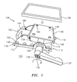
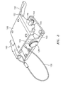
- FIGS. 1-6 depict perspective views of a display mounting apparatus 100 in assembled and disassembled states according to an embodiment.
- the display mounting apparatus 100 includes a base mount member 102, a pivot support member 104, and an upper mount member 106.
- the base mount member 102 includes a pair of pivot coupling lobes 108, where each of the pivot coupling lobes 108 includes a pivot attachment hole 110 such that the base mount member 102 includes a pair of the pivot attachment holes 110.
- the pivot coupling lobes 108 may extend from sidewalls 112 of the base mount member 102, where the sidewalls 112 are substantially perpendicular to an upper surface 114 of the base mount member 102.
- the base mount member 102 has a first end 116 and a second end 118 that is opposite the first end 116.
- the pair of pivot coupling lobes 108 is offset closer to the first end 116 than to the second end 118 of the base mount member 102, i.e., non-centered.
- the base mount member 102 also includes a plurality of fastener holes 120 to secure the display mounting apparatus 100 to a surface 122 of a vehicle using a plurality of fasteners (not depicted).
- the surface 122 of the vehicle may be a cockpit of an aircraft, such as cockpit 702 of vehicle 700 of FIG. 7 .
- the pivot support member 104 includes an upper mounting surface 124 and a locking pin passage 126, as best seen in FIGS. 5 and 6 .
- the pivot support member 104 is coupled to the base mount member 102 by a pivot pin 128 that passes through the pair of pivot attachment holes 110.
- the upper mounting surface 124 of the pivot support member 104 is substantially flat and cross shaped (e.g., "+"-shaped or "X"- shaped depending on the viewing angle).
- the pivot support member 104 also includes one of more angled lower surfaces 130, as best seen in FIG. 5 . The one of more angled lower surfaces 130 can limit rotation of the pivot support member 104 relative to the base mount member 102.
- the pivot pin 128 may be a ratcheting pivot pin that includes a locking handle 132 to enable inboard and outboard tilting of the pivot support member 104 at a plurality of discrete positions. For example, when the locking handle 132 is in a released or unlocked state, the pivot pin 128 can be manually rotated to change an angular position 134 of the pivot support member 104 and then locked in place. When the upper mount member 106 is coupled to the pivot support member 104, the change in angular position 134 results in tilting the upper mount member 106 and an EFB 136 secured to the upper mount member 106.
- Inboard tilting may be defined as movement that would tilt the EFB 136 toward a user of the EFB 136, and outboard tilting may be defined as movement that would tilt the EFB 136 away from a user of the EFB 136.
- the EFB 136 may be a special-purpose computer or a general-purpose computer, such as a tablet computer, that includes one or more EFB application programs and a display.
- the upper mount member 106 includes a display mounting surface 138, a lower surface 140, and a pair of locking pin holes 142 arranged to engage a locking pin 144 that passes through the pair of locking pin holes 142 and through the locking pin passage 126 of the pivot support member 104 when the upper mounting surface 124 of the pivot support member 104 is positioned proximate to the lower surface 140 of the upper mount member 106, as best seen in FIGS. 1 and 5 .
- the upper mount member 106 further includes a pair of locking pin engagement lobes 146, where each of the locking pin engagement lobes 146 includes one of the locking pin holes 142.
- the locking pin engagement lobes 146 may extend from sidewalls 148 of the upper mount member 106, where the sidewalls 148 are substantially perpendicular to the lower surface 140 of the upper mount member 106.
- the upper mount member 106 has a first end 150 and a second end 152 opposite the first end 150.
- the pair of locking pin engagement lobes 146 is substantially centered between the first end 150 and the second end 152 of the upper mount member 106, as best seen in FIG. 3 .
- the display mounting surface 138 of the upper mount member 106 can be secured to the EFB 136 of FIG. 1 .
- a plurality of fastener holes 154 on the upper mount member 106 may be used to secure the upper mount member 106 directly to the EFB 136 or to an intermediate adapter (not depicted) between the upper mount member 106 and the EFB 136.
- the base mount member 102 is inverted, rotated by about 90 degrees, and extended in length relative to the upper mount member 106.
- a length L1 of the base mount member 102 is greater than a length L2 of the upper mount member 106, as best seen in FIG. 4 .
- the base mount member 102 may include a greater number of fastener holes 120 than a number of fastener holes 154 in the upper mount member 106.
- the locking pin 144 can be tethered by a tether 156 to the base mount member 102 at a tether attachment block 158.
- the tether attachment block 158 may also act as a pivot stop that limits rotation of the pivot support member 104.
- the locking pin 144 can include a T-handle 160 and a plunger 162 operable to articulate one or more locking balls 164 in the locking pin 144.
- the tether 156 may also be coupled to the T-handle 160 of the locking pin 144. The tether 156 can prevent the locking pin 144 from being misplaced when removing the upper mount member 106 from the pivot support member 104.
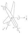
- FIG. 7 is a schematic view of a vehicle 700 in which the display mounting apparatus 100 can be installed according to an embodiment.
- the vehicle 700 is an example of an aircraft that includes a cockpit 702.
- the vehicle 700 may rotate about a pitch axis 704, a roll axis 706 and a yaw axis 708.
- the angular position 134 of the pivot support member 104 of FIG. 1 may be adjustable to enable inboard and outboard tilting of the pivot support member 104 at a plurality of discrete positions in substantial alignment with the pitch axis 704 of the vehicle 700.
- the angular position 134 of the pivot support member 104 of FIG. 1 may be adjustable to substantially align with the roll axis 706 of the vehicle 700.
- the display mounting apparatus 100 is installed at an angle between a front and side position of a pilot position in the cockpit 702
- adjustment of the angular position 134 of the pivot support member 104 of FIG. 1 may have a pitch axis 704 component and a roll axis 706 component relative to the vehicle 700.
- a method of installing the display mounting apparatus 100 of FIGS. 1-6 in the vehicle 700 of FIG. 7 includes coupling the base mount member 102 of the display mounting apparatus 100 to a surface 122 of the vehicle 700.
- the surface 122 of the vehicle 700 may be in the cockpit 702 of an aircraft.
- the base mount member 102 includes a pair of pivot attachment holes 110.
- An angular position 134 of the pivot support member 104 of the display mounting apparatus 100 can be adjusted.
- the pivot support member 104 includes an upper mounting surface 124 and a locking pin passage 126, where the pivot support member 104 is coupled to the base mount member 102 by a pivot pin 128 that passes through the pair of pivot attachment holes 110.
- the pivot pin 128 may be a ratcheting pivot pin that includes a locking handle 132 to adjust the angular position 134 of the pivot support member 104 by inboard or outboard tilting of the pivot support member 104 at a plurality of discrete positions.
- a lower surface 140 of the upper mount member 106 of the display mounting apparatus 100 is positioned proximate the upper mounting surface 124 of the pivot support member 104 to align the pair of locking pin holes 142 in the upper mount member 106 with the locking pin passage 126 of the pivot support member 104.
- the locking pin 144 is engaged through the pair of locking pin holes 142 in the upper mount member 106 and through the locking pin passage 126 of the pivot support member 104.
- the angular position adjustment and engagement of the locking pin 144 can be performed in any order, and the angular position 134 may be adjusted before and after the locking pin 144 is engaged.
- the display mounting surface 138 of the upper mount member 106 can be secured to the EFB 136 for use by a flight crew of the aircraft, e.g., vehicle 700.
- the plunger 162 of the locking pin 144 can be depressed to release the one or more locking balls 164 when an operator desires to remove the locking pin 144.
- the tether 156 Upon removal of the locking pin 144 from the upper mount member 106 and the pivot support member 104, the tether 156 retains the locking pin 144, and the EFB 136 can be freely moved about the cockpit 702 or removed entirely from the cockpit 702.
Landscapes
- Engineering & Computer Science (AREA)
- General Engineering & Computer Science (AREA)
- Mechanical Engineering (AREA)
- Aviation & Aerospace Engineering (AREA)
- Pivots And Pivotal Connections (AREA)
- Fittings On The Vehicle Exterior For Carrying Loads, And Devices For Holding Or Mounting Articles (AREA)
- Devices For Indicating Variable Information By Combining Individual Elements (AREA)
Abstract
Description
- The subject matter disclosed herein relates to a mounting apparatus. More specifically, the subject disclosure relates to a pivoting display mounting apparatus that enables display removal without using tools.
- In an aircraft cockpit, a flight crew can access information electronically using an electronic flight bag (EFB). The EFB typically includes reference materials stored as electronic documents or interactive applications. Examples of reference materials include an aircraft operating manual, a flight crew operating manual, and navigational charts. Other information that may be available to through an EFB includes aviation data and fuel calculations. EFBs can be implemented as special-purpose computers or as general purpose computing devices with EFB-specific software installed therein.
- Some aircraft include EFBs incorporated into the cockpit as an integrated, non-portal device. In other aircraft, EFBs are portable devices that must be secured during flight crew use. Installing an EFB in a fixed position may result in a degraded viewing experience depending upon glare from various light sources and differences in height of flight crew members as different flight crews share an aircraft over a period of time. EFBs may require periodic updates with new data files or application programs. Where on-board programming is not available for the EFB, it must be physically removed to install updates. Portable EFBs typically support removal from a secured position, but special tools may be needed to secure and remove EFBs from an aircraft.
- According to one aspect, a display mounting apparatus includes a base mount member, a pivot support member, and an upper mount member. The base mount member includes a pair of pivot attachment holes. The pivot support member includes an upper mounting surface and a locking pin passage. The pivot support member is coupled to the base mount member by a pivot pin that passes through the pair of pivot attachment holes. The upper mount member includes a display mounting surface, a lower surface, and a pair of locking pin holes arranged to engage a locking pin that passes through the pair of locking pin holes and through the locking pin passage of the pivot support member when the upper mounting surface of the pivot support member is positioned proximate to the lower surface of the upper mount member.
- According to another aspect, a method of installing a display mounting apparatus in a vehicle is provided. The method includes coupling a base mount member of the display mounting apparatus to a surface of the vehicle. The base mount member includes a pair of pivot attachment holes. An angular position of a pivot support member of the display mounting apparatus is adjusted. The pivot support member includes an upper mounting surface and a locking pin passage, where the pivot support member is coupled to the base mount member by a pivot pin that passes through the pair of pivot attachment holes. A lower surface of an upper mount member of the display mounting apparatus is positioned proximate the upper mounting surface of the pivot support member to align a pair of locking pin holes in the upper mount member with the locking pin passage of the pivot support member. A locking pin is engaged through the pair of locking pin holes in the upper mount member and through the locking pin passage of the pivot support member.
- The subject matter which is regarded as the invention is particularly pointed out and distinctly claimed in the claims at the conclusion of the specification. The foregoing and other features, and advantages of the invention are apparent from the following detailed description taken in conjunction with the accompanying drawings in which:
-
FIG. 1 is a perspective view of a display mounting apparatus according to an embodiment; -
FIG. 2 is another perspective view of the display mounting apparatus according to an embodiment; -
FIG. 3 is another perspective view of the display mounting apparatus according to an embodiment; -
FIG. 4 is another perspective view of the display mounting apparatus according to an embodiment; -
FIG. 5 is a perspective view of the display mounting apparatus in a disassembled state according to an embodiment; -
FIG. 6 is another perspective view of the display mounting apparatus in the disassembled state according to an embodiment; and -
FIG. 7 is a schematic view of a vehicle in which the display mounting apparatus can be installed according to an embodiment. - In an exemplary embodiment, a display mounting apparatus is provided that includes separable mount members. A base mount member can be fastened to a surface of a vehicle, such as on a surface in a cockpit of an aircraft. A pivot support member is coupled by a pivot pin to the base mount member. The pivot support member pivots or tilts about the pivot pin relative to the stationary base mount member. An upper mount member can be secured to an electronic flight bag (EFB) as a display. The EFB may be a special-purpose computer with mounting holes that can be directly coupled to the upper mount member. Alternatively, the EFB can be a general-purpose computer, such as a tablet computer, that includes one or more EFB application programs. When the EFB does not include mounting holes that are directly compatible with the upper mount member, an adapter can be used to couple the EFB to the upper mount member. The upper mount member can be secured to the pivot support member by a locking pin. The locking pin may pass through a pair of locking pin holes in the upper mount member and through a locking pin passage of the pivot support member when the locking pin holes are positioned at opposite ends of the locking pin passage. The locking pin may include T-handle and a plunger operable to articulate one or more locking balls in the locking pin. An operator can depress the plunger to release the one or more locking balls from a locked position in the locking pin, such that the locking pin can be removed. Thus, once the base mount member is attached to a surface of a vehicle, an operator can connect or remove, by hand without using any tools, the upper mount member to/from the pivot support member of the display mounting apparatus while the EFB is secured to the upper mount member.
- Turning now to the figures,
FIGS. 1-6 depict perspective views of adisplay mounting apparatus 100 in assembled and disassembled states according to an embodiment. As can be seen inFIG. 1 , thedisplay mounting apparatus 100 includes abase mount member 102, apivot support member 104, and anupper mount member 106. Thebase mount member 102 includes a pair ofpivot coupling lobes 108, where each of thepivot coupling lobes 108 includes apivot attachment hole 110 such that thebase mount member 102 includes a pair of thepivot attachment holes 110. Thepivot coupling lobes 108 may extend fromsidewalls 112 of thebase mount member 102, where thesidewalls 112 are substantially perpendicular to anupper surface 114 of thebase mount member 102. Thebase mount member 102 has afirst end 116 and asecond end 118 that is opposite thefirst end 116. The pair ofpivot coupling lobes 108 is offset closer to thefirst end 116 than to thesecond end 118 of thebase mount member 102, i.e., non-centered. Thebase mount member 102 also includes a plurality offastener holes 120 to secure thedisplay mounting apparatus 100 to asurface 122 of a vehicle using a plurality of fasteners (not depicted). Thesurface 122 of the vehicle may be a cockpit of an aircraft, such ascockpit 702 ofvehicle 700 ofFIG. 7 . - With continued reference to
FIGS. 1-6 , thepivot support member 104 includes anupper mounting surface 124 and alocking pin passage 126, as best seen inFIGS. 5 and6 . Thepivot support member 104 is coupled to thebase mount member 102 by apivot pin 128 that passes through the pair ofpivot attachment holes 110. Theupper mounting surface 124 of thepivot support member 104 is substantially flat and cross shaped (e.g., "+"-shaped or "X"- shaped depending on the viewing angle). Thepivot support member 104 also includes one of more angledlower surfaces 130, as best seen inFIG. 5 . The one of more angledlower surfaces 130 can limit rotation of thepivot support member 104 relative to thebase mount member 102. Thepivot pin 128 may be a ratcheting pivot pin that includes alocking handle 132 to enable inboard and outboard tilting of thepivot support member 104 at a plurality of discrete positions. For example, when thelocking handle 132 is in a released or unlocked state, thepivot pin 128 can be manually rotated to change anangular position 134 of thepivot support member 104 and then locked in place. When theupper mount member 106 is coupled to thepivot support member 104, the change inangular position 134 results in tilting theupper mount member 106 and anEFB 136 secured to theupper mount member 106. Inboard tilting may be defined as movement that would tilt theEFB 136 toward a user of theEFB 136, and outboard tilting may be defined as movement that would tilt theEFB 136 away from a user of theEFB 136. TheEFB 136 may be a special-purpose computer or a general-purpose computer, such as a tablet computer, that includes one or more EFB application programs and a display. - In an embodiment, the
upper mount member 106 includes adisplay mounting surface 138, alower surface 140, and a pair of lockingpin holes 142 arranged to engage alocking pin 144 that passes through the pair of lockingpin holes 142 and through thelocking pin passage 126 of thepivot support member 104 when the upper mountingsurface 124 of thepivot support member 104 is positioned proximate to thelower surface 140 of theupper mount member 106, as best seen inFIGS. 1 and5 . Theupper mount member 106 further includes a pair of lockingpin engagement lobes 146, where each of the lockingpin engagement lobes 146 includes one of the locking pin holes 142. The lockingpin engagement lobes 146 may extend fromsidewalls 148 of theupper mount member 106, where thesidewalls 148 are substantially perpendicular to thelower surface 140 of theupper mount member 106. Theupper mount member 106 has afirst end 150 and asecond end 152 opposite thefirst end 150. The pair of lockingpin engagement lobes 146 is substantially centered between thefirst end 150 and thesecond end 152 of theupper mount member 106, as best seen inFIG. 3 . Thedisplay mounting surface 138 of theupper mount member 106 can be secured to theEFB 136 ofFIG. 1 . A plurality of fastener holes 154 on theupper mount member 106 may be used to secure theupper mount member 106 directly to theEFB 136 or to an intermediate adapter (not depicted) between theupper mount member 106 and theEFB 136. - In comparing the
base mount member 102 to theupper mount member 106, it can be seen that thebase mount member 102 is inverted, rotated by about 90 degrees, and extended in length relative to theupper mount member 106. For example, a length L1 of thebase mount member 102 is greater than a length L2 of theupper mount member 106, as best seen inFIG. 4 . Additionally, thebase mount member 102 may include a greater number offastener holes 120 than a number offastener holes 154 in theupper mount member 106. - The
locking pin 144 can be tethered by atether 156 to thebase mount member 102 at atether attachment block 158. Thetether attachment block 158 may also act as a pivot stop that limits rotation of thepivot support member 104. Thelocking pin 144 can include a T-handle 160 and aplunger 162 operable to articulate one ormore locking balls 164 in thelocking pin 144. Thetether 156 may also be coupled to the T-handle 160 of thelocking pin 144. Thetether 156 can prevent thelocking pin 144 from being misplaced when removing theupper mount member 106 from thepivot support member 104. -
FIG. 7 is a schematic view of avehicle 700 in which thedisplay mounting apparatus 100 can be installed according to an embodiment. Thevehicle 700 is an example of an aircraft that includes acockpit 702. Thevehicle 700 may rotate about apitch axis 704, aroll axis 706 and ayaw axis 708. Where thedisplay mounting apparatus 100 is installed in front of a pilot position in thecockpit 702, theangular position 134 of thepivot support member 104 ofFIG. 1 may be adjustable to enable inboard and outboard tilting of thepivot support member 104 at a plurality of discrete positions in substantial alignment with thepitch axis 704 of thevehicle 700. Where thedisplay mounting apparatus 100 is installed beside a pilot position in thecockpit 702, theangular position 134 of thepivot support member 104 ofFIG. 1 may be adjustable to substantially align with theroll axis 706 of thevehicle 700. Where thedisplay mounting apparatus 100 is installed at an angle between a front and side position of a pilot position in thecockpit 702, adjustment of theangular position 134 of thepivot support member 104 ofFIG. 1 may have apitch axis 704 component and aroll axis 706 component relative to thevehicle 700. - A method of installing the
display mounting apparatus 100 ofFIGS. 1-6 in thevehicle 700 ofFIG. 7 includes coupling thebase mount member 102 of thedisplay mounting apparatus 100 to asurface 122 of thevehicle 700. Thesurface 122 of thevehicle 700 may be in thecockpit 702 of an aircraft. As previously described, thebase mount member 102 includes a pair of pivot attachment holes 110. Anangular position 134 of thepivot support member 104 of thedisplay mounting apparatus 100 can be adjusted. Thepivot support member 104 includes anupper mounting surface 124 and alocking pin passage 126, where thepivot support member 104 is coupled to thebase mount member 102 by apivot pin 128 that passes through the pair of pivot attachment holes 110. Thepivot pin 128 may be a ratcheting pivot pin that includes alocking handle 132 to adjust theangular position 134 of thepivot support member 104 by inboard or outboard tilting of thepivot support member 104 at a plurality of discrete positions. - A
lower surface 140 of theupper mount member 106 of thedisplay mounting apparatus 100 is positioned proximate the upper mountingsurface 124 of thepivot support member 104 to align the pair of lockingpin holes 142 in theupper mount member 106 with thelocking pin passage 126 of thepivot support member 104. Thelocking pin 144 is engaged through the pair of lockingpin holes 142 in theupper mount member 106 and through thelocking pin passage 126 of thepivot support member 104. The angular position adjustment and engagement of thelocking pin 144 can be performed in any order, and theangular position 134 may be adjusted before and after thelocking pin 144 is engaged. Thedisplay mounting surface 138 of theupper mount member 106 can be secured to theEFB 136 for use by a flight crew of the aircraft, e.g.,vehicle 700. - The
plunger 162 of thelocking pin 144 can be depressed to release the one ormore locking balls 164 when an operator desires to remove thelocking pin 144. Upon removal of thelocking pin 144 from theupper mount member 106 and thepivot support member 104, thetether 156 retains thelocking pin 144, and theEFB 136 can be freely moved about thecockpit 702 or removed entirely from thecockpit 702. - While the invention has been described in detail in connection with only a limited number of embodiments, it should be readily understood that the invention is not limited to such disclosed embodiments. Rather, the invention can be modified to incorporate any number of variations, alterations, substitutions or equivalent arrangements not heretofore described, but which are commensurate with the scope of the invention. Additionally, while various embodiments of the invention have been described, it is to be understood that aspects of the invention may include only some of the described embodiments. Accordingly, the invention is not to be seen as limited by the foregoing description, but is only limited by the scope of the appended claims.
Claims (15)
- A display mounting apparatus (100), comprising:a base mount member (102) comprising a pair of pivot attachment holes (110);a pivot support member (104) comprising an upper mounting surface (124) and a locking pin passage (126), the pivot support member (104) coupled to the base mount member (102) by a pivot pin (128) that passes through the pair of pivot attachment holes (110); andan upper mount member (106) comprising a display mounting surface (138), a lower surface (140), and a pair of locking pin holes (142) arranged to engage a locking pin (144) that passes through the pair of locking pin holes (142) and through the locking pin passage (126) of the pivot support member (104) when the upper mounting surface (124) of the pivot support member (104) is positioned proximate to the lower surface (140) of the upper mount member (106).
- The display mounting apparatus of claim 1, wherein the base mount member (102) further comprises a pair of pivot coupling lobes (108) and each of the pivot coupling lobes (108) includes one of the pivot attachment holes (110).
- The display mounting apparatus of claim 2, wherein the base mount member (102) comprises a first end (116) and a second end (118) opposite the first end (116), and the pair of pivot coupling lobes (108) is offset closer to the first end (116) than to the second end (118) of the base mount member (102).
- The display mounting apparatus of claim 1, 2 or 3, wherein the upper mounting surface (124) of the pivot support member (104) is substantially flat and cross shaped.
- The display mounting apparatus of any preceding claim, wherein the pivot pin (128) is a ratcheting pivot pin comprising a locking handle (132) to enable inboard and outboard tilting of the pivot support member (104) at a plurality of discrete positions.
- The display mounting apparatus of any preceding claim, further comprising the locking pin (144), wherein the locking pin (144) is tethered to the base mount member (102) at a tether attachment block (158).
- The display mounting apparatus of claim 6, wherein the tether attachment block (158) is a pivot stop that limits rotation of the pivot support member (104).
- The display mounting apparatus of claim 6 or 7, wherein the locking pin (144) comprises a T-handle (160) and a plunger (162) operable to articulate one or more locking balls (164) in the locking pin (144).
- The display mounting apparatus of any preceding claim, wherein the upper mount member (106) further comprises a pair of locking pin engagement lobes (146) and each of the locking pin engagement lobes (146) includes one of the locking pin holes (142).
- The display mounting apparatus of claim 9, wherein the upper mount member (106) comprises a first end (116) and a second end (118) opposite the first end (116), and the pair of locking pin engagement lobes (146) is substantially centered between the first end (116) and the second end (118) of the upper mount member (106).
- The display mounting apparatus of any preceding claim, wherein the base mount member (102) comprises a plurality of fastener holes (154) to secure the display mounting apparatus (100) to a surface of a vehicle (700) using a plurality of fasteners.
- The display mounting apparatus of claim 11, wherein the surface of the vehicle (700) is a cockpit of an aircraft (702), and the display mounting surface (138) of the upper mount member (106) is secured to an electronic flight bag (EFB).
- A method of installing a display mounting apparatus (100) in a vehicle (700), the method comprising:coupling a base mount member (102) of the display mounting apparatus (100) to a surface of the vehicle (700), the base mount member (102) comprising a pair of pivot attachment holes (110);adjusting an angular position of a pivot support member (104) of the display mounting apparatus (100), the pivot support member (104) comprising an upper mounting surface (124) and a locking pin passage (126), the pivot support member (104) coupled to the base mount member (102) by a pivot pin (128) that passes through the pair of pivot attachment holes (110);positioning a lower surface (140) of an upper mount member (106) of the display mounting apparatus (100) proximate the upper mounting surface (124) of the pivot support member (104) to align a pair of locking pin holes (142) in the upper mount member (106) with the locking pin passage (126) of the pivot support member (104); andengaging a locking pin (144) through the pair of locking pin holes (142) in the upper mount member (106) and through the locking pin passage (126) of the pivot support member (104).
- The method of claim 13, wherein the surface of the vehicle (700) is a cockpit of an aircraft (702), and a display mounting surface (138) of the upper mount member (106) is secured to an electronic flight bag (EFB).
- The method of claim 13 or 14, wherein the pivot pin (128) is a ratcheting pivot pin (128) comprising a locking handle (132) to adjust the angular position of the pivot support member (104) by inboard or outboard tilting of the pivot support member (104) at a plurality of discrete positions.
Applications Claiming Priority (1)
| Application Number | Priority Date | Filing Date | Title |
|---|---|---|---|
| US201462000724P | 2014-05-20 | 2014-05-20 |
Publications (2)
| Publication Number | Publication Date |
|---|---|
| EP2947370A1 true EP2947370A1 (en) | 2015-11-25 |
| EP2947370B1 EP2947370B1 (en) | 2018-07-04 |
Family
ID=53181150
Family Applications (1)
| Application Number | Title | Priority Date | Filing Date |
|---|---|---|---|
| EP15168126.9A Active EP2947370B1 (en) | 2014-05-20 | 2015-05-19 | Display mounting apparatus |
Country Status (4)
| Country | Link |
|---|---|
| US (2) | US9446854B2 (en) |
| EP (1) | EP2947370B1 (en) |
| BR (1) | BR102015006823B1 (en) |
| CA (1) | CA2887536C (en) |
Cited By (1)
| Publication number | Priority date | Publication date | Assignee | Title |
|---|---|---|---|---|
| CN106275468A (en) * | 2016-08-17 | 2017-01-04 | 哈尔滨飞机工业集团有限责任公司 | A kind of helicopter below deck equipment mounting bracket |
Families Citing this family (8)
| Publication number | Priority date | Publication date | Assignee | Title |
|---|---|---|---|---|
| BR102015006823B1 (en) | 2014-05-20 | 2020-11-10 | Rosemount Aerospace, Inc | display mount apparatus, and method for installing a display mount apparatus on a vehicle |
| EP3256648B1 (en) * | 2015-02-10 | 2019-10-30 | Ozkan, Aydin | A connection adapter |
| CN109296628B (en) * | 2018-12-09 | 2020-09-11 | 中国航空工业集团公司洛阳电光设备研究所 | A high-precision rotary shaft quick locking device |
| USD943094S1 (en) * | 2019-08-16 | 2022-02-08 | Robert Bosch Gmbh | Mount for an indicator or instrument |
| USD943093S1 (en) * | 2019-08-16 | 2022-02-08 | Robert Bosch Gmbh | Mount for an indicator or instrument |
| USD942004S1 (en) * | 2019-08-16 | 2022-01-25 | Robert Bosch Gmbh | Mount for an indicator or instrument |
| USD951762S1 (en) * | 2020-11-25 | 2022-05-17 | Mafi Ab | Fastening device |
| US11235710B1 (en) * | 2021-07-06 | 2022-02-01 | Matthew Shumaker | Display bracket and mount apparatus and methods of using the same |
Citations (2)
| Publication number | Priority date | Publication date | Assignee | Title |
|---|---|---|---|---|
| EP2639489A2 (en) * | 2012-03-16 | 2013-09-18 | Ming-Hsien Huang | Angle-adjustable mounting apparatus |
| EP2896567A1 (en) * | 2014-01-16 | 2015-07-22 | Rosemount Aerospace Inc. | Device mount |
Family Cites Families (13)
| Publication number | Priority date | Publication date | Assignee | Title |
|---|---|---|---|---|
| US2500048A (en) * | 1947-01-30 | 1950-03-07 | Eastman Kodak Co | Clamping device |
| US4763151A (en) * | 1987-05-14 | 1988-08-09 | Klinger Joseph K | Universal tripod head |
| US5769369A (en) | 1995-04-28 | 1998-06-23 | Meinel; James | Mobile office stand for supporting a portable computer or electronic organizer in vehicles |
| US6588719B1 (en) | 2002-09-10 | 2003-07-08 | Hollingsead International, Inc. | Mounting and support bracket |
| TWM254544U (en) * | 2003-10-29 | 2005-01-01 | Chin-Chih Lin | Pivot shaft structure for flat displaying device |
| US7686250B2 (en) | 2006-01-20 | 2010-03-30 | Fortes Hugo L | Electronic display mount |
| US8231081B2 (en) | 2006-01-20 | 2012-07-31 | Avionics Support Group, Inc. | Electronic display mount |
| US8308114B2 (en) * | 2009-02-25 | 2012-11-13 | Tensolite LLC | Electronic flight bag mounting bracket |
| US8701953B2 (en) | 2009-10-09 | 2014-04-22 | Raytheon Company | Electronic flight bag mounting system |
| JP2013258531A (en) * | 2012-06-12 | 2013-12-26 | Yamaha Corp | Apparatus attachment device |
| CN103671473A (en) * | 2012-08-30 | 2014-03-26 | 光宝电子(广州)有限公司 | Hinge |
| US9416912B2 (en) * | 2013-03-15 | 2016-08-16 | Lilitab LLC | Wall mount with configurable stops |
| BR102015006823B1 (en) | 2014-05-20 | 2020-11-10 | Rosemount Aerospace, Inc | display mount apparatus, and method for installing a display mount apparatus on a vehicle |
-
2015
- 2015-03-26 BR BR102015006823-9A patent/BR102015006823B1/en active IP Right Grant
- 2015-04-08 CA CA2887536A patent/CA2887536C/en active Active
- 2015-05-19 EP EP15168126.9A patent/EP2947370B1/en active Active
- 2015-05-20 US US14/717,201 patent/US9446854B2/en active Active
-
2016
- 2016-08-23 US US15/244,388 patent/US9752722B2/en active Active
Patent Citations (2)
| Publication number | Priority date | Publication date | Assignee | Title |
|---|---|---|---|---|
| EP2639489A2 (en) * | 2012-03-16 | 2013-09-18 | Ming-Hsien Huang | Angle-adjustable mounting apparatus |
| EP2896567A1 (en) * | 2014-01-16 | 2015-07-22 | Rosemount Aerospace Inc. | Device mount |
Cited By (1)
| Publication number | Priority date | Publication date | Assignee | Title |
|---|---|---|---|---|
| CN106275468A (en) * | 2016-08-17 | 2017-01-04 | 哈尔滨飞机工业集团有限责任公司 | A kind of helicopter below deck equipment mounting bracket |
Also Published As
| Publication number | Publication date |
|---|---|
| US9752722B2 (en) | 2017-09-05 |
| CA2887536C (en) | 2022-06-28 |
| BR102015006823B1 (en) | 2020-11-10 |
| BR102015006823A2 (en) | 2016-03-08 |
| US20150336682A1 (en) | 2015-11-26 |
| CA2887536A1 (en) | 2015-11-20 |
| US9446854B2 (en) | 2016-09-20 |
| US20160356416A1 (en) | 2016-12-08 |
| EP2947370B1 (en) | 2018-07-04 |
Similar Documents
| Publication | Publication Date | Title |
|---|---|---|
| EP2947370B1 (en) | Display mounting apparatus | |
| EP2401199B1 (en) | Electronic flight bag mounting bracket | |
| US10428998B2 (en) | Gimbal structure and gear adjusting mechanism thereof | |
| US9027892B2 (en) | Rotating electronic display mount | |
| EP2808593B1 (en) | Rotating electronic display adapter | |
| US20110084106A1 (en) | Electronic Flight Bag Mounting System | |
| EP3712699B1 (en) | Camera gimbal mount system | |
| US20110101058A1 (en) | Pivot mount assembly | |
| US20080296454A1 (en) | Convertible C-Clamp | |
| US20170188123A1 (en) | Articulating, self retained on-wall bracket mounting system | |
| US20120261520A1 (en) | Articulating yoke mount | |
| CN107000852A (en) | Attachment means, head assembly and picture shooting assembly with the attachment means | |
| CN104919241B (en) | Mounting system device for positioning electronic equipment | |
| US6588719B1 (en) | Mounting and support bracket | |
| WO2019000201A1 (en) | Tripod head structure, tripod head having same and photographing assembly | |
| CN106254728B (en) | Camera adjustment mechanism and method and aircraft surveillance system | |
| US9281857B1 (en) | Phone holder | |
| CN104848009A (en) | Fixing device and holder with the same | |
| US20210179288A1 (en) | Airplane Cockpit Tablet Mount | |
| JP4424328B2 (en) | Thin display device having wall mounting function and wall mounting device for mounting thin display device on wall surface | |
| US20250153655A1 (en) | Quick install tablet support | |
| CN223618922U (en) | Bracket for holding electronic flight bag |
Legal Events
| Date | Code | Title | Description |
|---|---|---|---|
| PUAI | Public reference made under article 153(3) epc to a published international application that has entered the european phase |
Free format text: ORIGINAL CODE: 0009012 |
|
| AK | Designated contracting states |
Kind code of ref document: A1 Designated state(s): AL AT BE BG CH CY CZ DE DK EE ES FI FR GB GR HR HU IE IS IT LI LT LU LV MC MK MT NL NO PL PT RO RS SE SI SK SM TR |
|
| AX | Request for extension of the european patent |
Extension state: BA ME |
|
| 17P | Request for examination filed |
Effective date: 20160525 |
|
| RBV | Designated contracting states (corrected) |
Designated state(s): AL AT BE BG CH CY CZ DE DK EE ES FI FR GB GR HR HU IE IS IT LI LT LU LV MC MK MT NL NO PL PT RO RS SE SI SK SM TR |
|
| STAA | Information on the status of an ep patent application or granted ep patent |
Free format text: STATUS: EXAMINATION IS IN PROGRESS |
|
| 17Q | First examination report despatched |
Effective date: 20161104 |
|
| GRAP | Despatch of communication of intention to grant a patent |
Free format text: ORIGINAL CODE: EPIDOSNIGR1 |
|
| STAA | Information on the status of an ep patent application or granted ep patent |
Free format text: STATUS: GRANT OF PATENT IS INTENDED |
|
| INTG | Intention to grant announced |
Effective date: 20171208 |
|
| RIN1 | Information on inventor provided before grant (corrected) |
Inventor name: FARNES, BRIAN Inventor name: TSCHANN, MATTHEW |
|
| GRAS | Grant fee paid |
Free format text: ORIGINAL CODE: EPIDOSNIGR3 |
|
| GRAA | (expected) grant |
Free format text: ORIGINAL CODE: 0009210 |
|
| STAA | Information on the status of an ep patent application or granted ep patent |
Free format text: STATUS: THE PATENT HAS BEEN GRANTED |
|
| AK | Designated contracting states |
Kind code of ref document: B1 Designated state(s): AL AT BE BG CH CY CZ DE DK EE ES FI FR GB GR HR HU IE IS IT LI LT LU LV MC MK MT NL NO PL PT RO RS SE SI SK SM TR |
|
| REG | Reference to a national code |
Ref country code: GB Ref legal event code: FG4D |
|
| REG | Reference to a national code |
Ref country code: CH Ref legal event code: EP |
|
| REG | Reference to a national code |
Ref country code: AT Ref legal event code: REF Ref document number: 1014897 Country of ref document: AT Kind code of ref document: T Effective date: 20180715 |
|
| REG | Reference to a national code |
Ref country code: IE Ref legal event code: FG4D |
|
| REG | Reference to a national code |
Ref country code: DE Ref legal event code: R096 Ref document number: 602015012909 Country of ref document: DE |
|
| REG | Reference to a national code |
Ref country code: NL Ref legal event code: MP Effective date: 20180704 |
|
| REG | Reference to a national code |
Ref country code: LT Ref legal event code: MG4D |
|
| REG | Reference to a national code |
Ref country code: AT Ref legal event code: MK05 Ref document number: 1014897 Country of ref document: AT Kind code of ref document: T Effective date: 20180704 |
|
| PG25 | Lapsed in a contracting state [announced via postgrant information from national office to epo] |
Ref country code: NL Free format text: LAPSE BECAUSE OF FAILURE TO SUBMIT A TRANSLATION OF THE DESCRIPTION OR TO PAY THE FEE WITHIN THE PRESCRIBED TIME-LIMIT Effective date: 20180704 |
|
| PG25 | Lapsed in a contracting state [announced via postgrant information from national office to epo] |
Ref country code: FI Free format text: LAPSE BECAUSE OF FAILURE TO SUBMIT A TRANSLATION OF THE DESCRIPTION OR TO PAY THE FEE WITHIN THE PRESCRIBED TIME-LIMIT Effective date: 20180704 Ref country code: RS Free format text: LAPSE BECAUSE OF FAILURE TO SUBMIT A TRANSLATION OF THE DESCRIPTION OR TO PAY THE FEE WITHIN THE PRESCRIBED TIME-LIMIT Effective date: 20180704 Ref country code: SE Free format text: LAPSE BECAUSE OF FAILURE TO SUBMIT A TRANSLATION OF THE DESCRIPTION OR TO PAY THE FEE WITHIN THE PRESCRIBED TIME-LIMIT Effective date: 20180704 Ref country code: BG Free format text: LAPSE BECAUSE OF FAILURE TO SUBMIT A TRANSLATION OF THE DESCRIPTION OR TO PAY THE FEE WITHIN THE PRESCRIBED TIME-LIMIT Effective date: 20181004 Ref country code: GR Free format text: LAPSE BECAUSE OF FAILURE TO SUBMIT A TRANSLATION OF THE DESCRIPTION OR TO PAY THE FEE WITHIN THE PRESCRIBED TIME-LIMIT Effective date: 20181005 Ref country code: NO Free format text: LAPSE BECAUSE OF FAILURE TO SUBMIT A TRANSLATION OF THE DESCRIPTION OR TO PAY THE FEE WITHIN THE PRESCRIBED TIME-LIMIT Effective date: 20181004 Ref country code: IS Free format text: LAPSE BECAUSE OF FAILURE TO SUBMIT A TRANSLATION OF THE DESCRIPTION OR TO PAY THE FEE WITHIN THE PRESCRIBED TIME-LIMIT Effective date: 20181104 Ref country code: PL Free format text: LAPSE BECAUSE OF FAILURE TO SUBMIT A TRANSLATION OF THE DESCRIPTION OR TO PAY THE FEE WITHIN THE PRESCRIBED TIME-LIMIT Effective date: 20180704 Ref country code: AT Free format text: LAPSE BECAUSE OF FAILURE TO SUBMIT A TRANSLATION OF THE DESCRIPTION OR TO PAY THE FEE WITHIN THE PRESCRIBED TIME-LIMIT Effective date: 20180704 Ref country code: LT Free format text: LAPSE BECAUSE OF FAILURE TO SUBMIT A TRANSLATION OF THE DESCRIPTION OR TO PAY THE FEE WITHIN THE PRESCRIBED TIME-LIMIT Effective date: 20180704 Ref country code: CZ Free format text: LAPSE BECAUSE OF FAILURE TO SUBMIT A TRANSLATION OF THE DESCRIPTION OR TO PAY THE FEE WITHIN THE PRESCRIBED TIME-LIMIT Effective date: 20180704 |
|
| PG25 | Lapsed in a contracting state [announced via postgrant information from national office to epo] |
Ref country code: HR Free format text: LAPSE BECAUSE OF FAILURE TO SUBMIT A TRANSLATION OF THE DESCRIPTION OR TO PAY THE FEE WITHIN THE PRESCRIBED TIME-LIMIT Effective date: 20180704 Ref country code: AL Free format text: LAPSE BECAUSE OF FAILURE TO SUBMIT A TRANSLATION OF THE DESCRIPTION OR TO PAY THE FEE WITHIN THE PRESCRIBED TIME-LIMIT Effective date: 20180704 Ref country code: LV Free format text: LAPSE BECAUSE OF FAILURE TO SUBMIT A TRANSLATION OF THE DESCRIPTION OR TO PAY THE FEE WITHIN THE PRESCRIBED TIME-LIMIT Effective date: 20180704 Ref country code: ES Free format text: LAPSE BECAUSE OF FAILURE TO SUBMIT A TRANSLATION OF THE DESCRIPTION OR TO PAY THE FEE WITHIN THE PRESCRIBED TIME-LIMIT Effective date: 20180704 |
|
| REG | Reference to a national code |
Ref country code: DE Ref legal event code: R097 Ref document number: 602015012909 Country of ref document: DE |
|
| PG25 | Lapsed in a contracting state [announced via postgrant information from national office to epo] |
Ref country code: RO Free format text: LAPSE BECAUSE OF FAILURE TO SUBMIT A TRANSLATION OF THE DESCRIPTION OR TO PAY THE FEE WITHIN THE PRESCRIBED TIME-LIMIT Effective date: 20180704 Ref country code: EE Free format text: LAPSE BECAUSE OF FAILURE TO SUBMIT A TRANSLATION OF THE DESCRIPTION OR TO PAY THE FEE WITHIN THE PRESCRIBED TIME-LIMIT Effective date: 20180704 Ref country code: IT Free format text: LAPSE BECAUSE OF FAILURE TO SUBMIT A TRANSLATION OF THE DESCRIPTION OR TO PAY THE FEE WITHIN THE PRESCRIBED TIME-LIMIT Effective date: 20180704 |
|
| PLBE | No opposition filed within time limit |
Free format text: ORIGINAL CODE: 0009261 |
|
| STAA | Information on the status of an ep patent application or granted ep patent |
Free format text: STATUS: NO OPPOSITION FILED WITHIN TIME LIMIT |
|
| PG25 | Lapsed in a contracting state [announced via postgrant information from national office to epo] |
Ref country code: DK Free format text: LAPSE BECAUSE OF FAILURE TO SUBMIT A TRANSLATION OF THE DESCRIPTION OR TO PAY THE FEE WITHIN THE PRESCRIBED TIME-LIMIT Effective date: 20180704 Ref country code: SM Free format text: LAPSE BECAUSE OF FAILURE TO SUBMIT A TRANSLATION OF THE DESCRIPTION OR TO PAY THE FEE WITHIN THE PRESCRIBED TIME-LIMIT Effective date: 20180704 Ref country code: SK Free format text: LAPSE BECAUSE OF FAILURE TO SUBMIT A TRANSLATION OF THE DESCRIPTION OR TO PAY THE FEE WITHIN THE PRESCRIBED TIME-LIMIT Effective date: 20180704 |
|
| 26N | No opposition filed |
Effective date: 20190405 |
|
| PG25 | Lapsed in a contracting state [announced via postgrant information from national office to epo] |
Ref country code: SI Free format text: LAPSE BECAUSE OF FAILURE TO SUBMIT A TRANSLATION OF THE DESCRIPTION OR TO PAY THE FEE WITHIN THE PRESCRIBED TIME-LIMIT Effective date: 20180704 |
|
| REG | Reference to a national code |
Ref country code: CH Ref legal event code: PL |
|
| PG25 | Lapsed in a contracting state [announced via postgrant information from national office to epo] |
Ref country code: LI Free format text: LAPSE BECAUSE OF NON-PAYMENT OF DUE FEES Effective date: 20190531 Ref country code: CH Free format text: LAPSE BECAUSE OF NON-PAYMENT OF DUE FEES Effective date: 20190531 Ref country code: MC Free format text: LAPSE BECAUSE OF FAILURE TO SUBMIT A TRANSLATION OF THE DESCRIPTION OR TO PAY THE FEE WITHIN THE PRESCRIBED TIME-LIMIT Effective date: 20180704 |
|
| REG | Reference to a national code |
Ref country code: BE Ref legal event code: MM Effective date: 20190531 |
|
| PG25 | Lapsed in a contracting state [announced via postgrant information from national office to epo] |
Ref country code: LU Free format text: LAPSE BECAUSE OF NON-PAYMENT OF DUE FEES Effective date: 20190519 |
|
| PG25 | Lapsed in a contracting state [announced via postgrant information from national office to epo] |
Ref country code: TR Free format text: LAPSE BECAUSE OF FAILURE TO SUBMIT A TRANSLATION OF THE DESCRIPTION OR TO PAY THE FEE WITHIN THE PRESCRIBED TIME-LIMIT Effective date: 20180704 |
|
| PG25 | Lapsed in a contracting state [announced via postgrant information from national office to epo] |
Ref country code: IE Free format text: LAPSE BECAUSE OF NON-PAYMENT OF DUE FEES Effective date: 20190519 |
|
| PG25 | Lapsed in a contracting state [announced via postgrant information from national office to epo] |
Ref country code: BE Free format text: LAPSE BECAUSE OF NON-PAYMENT OF DUE FEES Effective date: 20190531 |
|
| PG25 | Lapsed in a contracting state [announced via postgrant information from national office to epo] |
Ref country code: PT Free format text: LAPSE BECAUSE OF FAILURE TO SUBMIT A TRANSLATION OF THE DESCRIPTION OR TO PAY THE FEE WITHIN THE PRESCRIBED TIME-LIMIT Effective date: 20181104 |
|
| PG25 | Lapsed in a contracting state [announced via postgrant information from national office to epo] |
Ref country code: CY Free format text: LAPSE BECAUSE OF FAILURE TO SUBMIT A TRANSLATION OF THE DESCRIPTION OR TO PAY THE FEE WITHIN THE PRESCRIBED TIME-LIMIT Effective date: 20180704 |
|
| PG25 | Lapsed in a contracting state [announced via postgrant information from national office to epo] |
Ref country code: HU Free format text: LAPSE BECAUSE OF FAILURE TO SUBMIT A TRANSLATION OF THE DESCRIPTION OR TO PAY THE FEE WITHIN THE PRESCRIBED TIME-LIMIT; INVALID AB INITIO Effective date: 20150519 Ref country code: MT Free format text: LAPSE BECAUSE OF FAILURE TO SUBMIT A TRANSLATION OF THE DESCRIPTION OR TO PAY THE FEE WITHIN THE PRESCRIBED TIME-LIMIT Effective date: 20180704 |
|
| PG25 | Lapsed in a contracting state [announced via postgrant information from national office to epo] |
Ref country code: MK Free format text: LAPSE BECAUSE OF FAILURE TO SUBMIT A TRANSLATION OF THE DESCRIPTION OR TO PAY THE FEE WITHIN THE PRESCRIBED TIME-LIMIT Effective date: 20180704 |
|
| PGFP | Annual fee paid to national office [announced via postgrant information from national office to epo] |
Ref country code: DE Payment date: 20250423 Year of fee payment: 11 |
|
| PGFP | Annual fee paid to national office [announced via postgrant information from national office to epo] |
Ref country code: GB Payment date: 20250423 Year of fee payment: 11 |
|
| PGFP | Annual fee paid to national office [announced via postgrant information from national office to epo] |
Ref country code: FR Payment date: 20250423 Year of fee payment: 11 |
|
| P01 | Opt-out of the competence of the unified patent court (upc) registered |
Free format text: CASE NUMBER: UPC_APP_0016751_2947370/2025 Effective date: 20251210 |