EP2808593B1 - Rotating electronic display adapter - Google Patents
Rotating electronic display adapter Download PDFInfo
- Publication number
- EP2808593B1 EP2808593B1 EP14169346.5A EP14169346A EP2808593B1 EP 2808593 B1 EP2808593 B1 EP 2808593B1 EP 14169346 A EP14169346 A EP 14169346A EP 2808593 B1 EP2808593 B1 EP 2808593B1
- Authority
- EP
- European Patent Office
- Prior art keywords
- display device
- barrel
- adapter
- keys
- assembly
- Prior art date
- Legal status (The legal status is an assumption and is not a legal conclusion. Google has not performed a legal analysis and makes no representation as to the accuracy of the status listed.)
- Active
Links
Images


Classifications
-
- B—PERFORMING OPERATIONS; TRANSPORTING
- B64—AIRCRAFT; AVIATION; COSMONAUTICS
- B64D—EQUIPMENT FOR FITTING IN OR TO AIRCRAFT; FLIGHT SUITS; PARACHUTES; ARRANGEMENTS OR MOUNTING OF POWER PLANTS OR PROPULSION TRANSMISSIONS IN AIRCRAFT
- B64D43/00—Arrangements or adaptations of instruments
-
- F—MECHANICAL ENGINEERING; LIGHTING; HEATING; WEAPONS; BLASTING
- F16—ENGINEERING ELEMENTS AND UNITS; GENERAL MEASURES FOR PRODUCING AND MAINTAINING EFFECTIVE FUNCTIONING OF MACHINES OR INSTALLATIONS; THERMAL INSULATION IN GENERAL
- F16M—FRAMES, CASINGS OR BEDS OF ENGINES, MACHINES OR APPARATUS, NOT SPECIFIC TO ENGINES, MACHINES OR APPARATUS PROVIDED FOR ELSEWHERE; STANDS; SUPPORTS
- F16M11/00—Stands or trestles as supports for apparatus or articles placed thereon Stands for scientific apparatus such as gravitational force meters
- F16M11/02—Heads
- F16M11/04—Means for attachment of apparatus; Means allowing adjustment of the apparatus relatively to the stand
- F16M11/041—Allowing quick release of the apparatus
-
- F—MECHANICAL ENGINEERING; LIGHTING; HEATING; WEAPONS; BLASTING
- F16—ENGINEERING ELEMENTS AND UNITS; GENERAL MEASURES FOR PRODUCING AND MAINTAINING EFFECTIVE FUNCTIONING OF MACHINES OR INSTALLATIONS; THERMAL INSULATION IN GENERAL
- F16M—FRAMES, CASINGS OR BEDS OF ENGINES, MACHINES OR APPARATUS, NOT SPECIFIC TO ENGINES, MACHINES OR APPARATUS PROVIDED FOR ELSEWHERE; STANDS; SUPPORTS
- F16M11/00—Stands or trestles as supports for apparatus or articles placed thereon Stands for scientific apparatus such as gravitational force meters
- F16M11/02—Heads
- F16M11/04—Means for attachment of apparatus; Means allowing adjustment of the apparatus relatively to the stand
- F16M11/06—Means for attachment of apparatus; Means allowing adjustment of the apparatus relatively to the stand allowing pivoting
- F16M11/08—Means for attachment of apparatus; Means allowing adjustment of the apparatus relatively to the stand allowing pivoting around a vertical axis, e.g. panoramic heads
-
- F—MECHANICAL ENGINEERING; LIGHTING; HEATING; WEAPONS; BLASTING
- F16—ENGINEERING ELEMENTS AND UNITS; GENERAL MEASURES FOR PRODUCING AND MAINTAINING EFFECTIVE FUNCTIONING OF MACHINES OR INSTALLATIONS; THERMAL INSULATION IN GENERAL
- F16M—FRAMES, CASINGS OR BEDS OF ENGINES, MACHINES OR APPARATUS, NOT SPECIFIC TO ENGINES, MACHINES OR APPARATUS PROVIDED FOR ELSEWHERE; STANDS; SUPPORTS
- F16M13/00—Other supports for positioning apparatus or articles; Means for steadying hand-held apparatus or articles
- F16M13/02—Other supports for positioning apparatus or articles; Means for steadying hand-held apparatus or articles for supporting on, or attaching to, an object, e.g. tree, gate, window-frame, cycle
- F16M13/022—Other supports for positioning apparatus or articles; Means for steadying hand-held apparatus or articles for supporting on, or attaching to, an object, e.g. tree, gate, window-frame, cycle repositionable
-
- F—MECHANICAL ENGINEERING; LIGHTING; HEATING; WEAPONS; BLASTING
- F16—ENGINEERING ELEMENTS AND UNITS; GENERAL MEASURES FOR PRODUCING AND MAINTAINING EFFECTIVE FUNCTIONING OF MACHINES OR INSTALLATIONS; THERMAL INSULATION IN GENERAL
- F16M—FRAMES, CASINGS OR BEDS OF ENGINES, MACHINES OR APPARATUS, NOT SPECIFIC TO ENGINES, MACHINES OR APPARATUS PROVIDED FOR ELSEWHERE; STANDS; SUPPORTS
- F16M2200/00—Details of stands or supports
- F16M2200/02—Locking means
- F16M2200/021—Locking means for rotational movement
- F16M2200/024—Locking means for rotational movement by positive interaction, e.g. male-female connections
-
- Y—GENERAL TAGGING OF NEW TECHNOLOGICAL DEVELOPMENTS; GENERAL TAGGING OF CROSS-SECTIONAL TECHNOLOGIES SPANNING OVER SEVERAL SECTIONS OF THE IPC; TECHNICAL SUBJECTS COVERED BY FORMER USPC CROSS-REFERENCE ART COLLECTIONS [XRACs] AND DIGESTS
- Y10—TECHNICAL SUBJECTS COVERED BY FORMER USPC
- Y10T—TECHNICAL SUBJECTS COVERED BY FORMER US CLASSIFICATION
- Y10T403/00—Joints and connections
- Y10T403/70—Interfitted members
Definitions
- the subject invention relates to improvements in mounts for portable electronic displays, and more particularly, to a rotating adapter for mounting a portable electronic flight bag (EFB) on a supporting surface within the cockpit of an aircraft.
- EFB portable electronic flight bag
- An EFB is an electronic display device that a pilot may use for preflight check lists and similar activities.
- EFB's are generally handheld, portable devices that a pilot can take from flight to flight. Information about a pilot's flight may be preloaded onto the EFB so that the pilot can access it prior to, during and after the flight.
- a pilot may have simply placed an EFB loosely within the cockpit of an airplane, e.g., on the floor or on a console, which could lead to problems during the flight.
- the EFB could become lost among other items in the cockpit, or the position of the EFB might shift during the flight.
- the EFB could become damaged if it is not secured to a fixed surface within the cockpit.
- Class 1 devices are standard commercial-off-the-shelf (COTS) equipment such as laptops or handheld electronic devices. These devices are used as loose equipment and are typically stowed during critical phases of flight.
- COTS commercial-off-the-shelf
- a Class 1 EFB is considered a Portable Electronic Device (PED). These may connect to aircraft power and interface to other systems via certified (STC) docking station and/or power source. This would allow the Class 1 device to interface with other systems through the certified interface and other devices through an expansion port interface.
- STC certified
- Class 2 devices are also Portable Electronic Devices, and range from modified COTS equipment to purpose-built devices. They are typically mounted in the aircraft with the display being viewable to the pilot during all phases of flight. Mounts can include certified structural mounting devices or kneeboard devices. These devices may connect to aircraft power and data sources, e.g. through an ARINC 429 interface.
- a Class 2 EFB can be used for bi-directional data communication with other aircraft systems. In this class, a single line replaceable unit (LRU) would be an optimal solution based on the ease of installation and replacement.
- LRU single line replaceable unit
- Class 3 devices are considered "installed equipment" and are subject to airworthiness requirements defined by the FAA. Unlike PEDs, these devices must be under design control. The hardware is subject to a limited number ofRTCA DO-160E requirements (for non-essential equipment--typical crash safety and Conducted and Radiated Emissions (EMC) testing). There may also be certain requirements for software. Class 3 EFBs are typically installed under STC or other airworthiness approval.
- Mounting brackets used for Class 2 and Class 3 hardware typically do not permit easy removal of the electronic equipment. The orientation and/or position of the electronic equipment also cannot be easily changed to accommodate user preference. Those mounting brackets that do permit adjustment, require considerable manipulation with both hands, which can be distracting and inconvenient for the pilot or other operator.
- US 5 870 642 discloses a panoramic support for a camera having a rotatable indexing head.
- US 2008/0251675 A1 discloses a rotating pedestal with an integrated locking mechanism.
- the subject invention is directed to a new and useful assembly for mounting an electronic display device to a supporting structure, such as a console, within the cockpit of an aircraft, as defined in the appended claims.
- the assembly includes an adapter portion configured for attachment to a rear surface of the electronic display device and a base portion configured to be mounted to a fixed structure, such as a console, in the cockpit of the aircraft.
- the adapter portion of the mounting assembly has a mounting plate for securement to the rear surface of the display device with a plurality of fasteners, and a cylindrical barrel portion that extends away from the rear surface of the display device.
- the barrel portion may have three circumferentially disposed radially outwardly extending keys.
- the barrel portion further includes a first radially inwardly extending recess corresponding to a landscape position of the display device and a second radially inwardly extending recess corresponding to a portrait position of the display device.
- the base portion of the mounting assembly includes an upper surface or wall with a circular reception port formed therein for receiving the barrel of the adapter portion.
- the reception port may have three radially outwardly extending circumferentially disposed keyways formed therein for receiving the three corresponding keys formed on the barrel of the adapter portion.
- the mounting assembly includes a manually operated plunger operatively associated with the base portion for selectively engaging the first and second recesses in the barrel of the adapter portion to prevent relative rotation of the adapter portion and the base portion.
- a locking nut may also be provided for selectively securing the plunger in an engagement position relative to the base portion.
- the three keys and keyways are positioned so that an initial engagement position of the barrel within the reception port corresponds to the display device having an orientation that is 30° clockwise from the landscape position of the display device and 120° clockwise from the portrait position of the display device.
- the barrel preferably includes a circumferential slot that is located axially above the three keys for engaging an annular retaining lip that surrounds the reception port in the upper surface of the base portion.
- the adapter portion may also include a plurality of spring loaded plungers retained in the barrel and mounted to bear against a bottom plate of the base portion to provide pressure against the retaining lip to add resistance against the rotation of the barrel within the reception port.
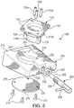
- Fig. 1 an electronic display device 10 that a pilot may use for preflight check lists and similar activities within the cockpit of an aircraft.
- the electronic display device 10 is removably mounted to a supporting structure or console 12 in the cockpit of an aircraft using the mounting assembly of the subject invention, which is described in greater detail herein below.
- the mounting assembly of the subject invention enables a pilot to easily and quickly mount the electronic display device 10 to a supporting surface or console 12 in the cockpit of an aircraft without any tools, fasteners or latches.
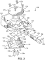
- Mounting assembly 100 includes two main components. These components include an adapter portion 110 configured for attachment to a rear surface of the electronic display device 10 and a base portion 210 configured to be mounted to the console 12 or other fixed structure in the cockpit of an aircraft.
- the adapter portion 110 of mounting assembly 100 has a mounting plate or flange 112 having a plurality of apertures 114 formed therein.
- the apertures 114 accommodate threaded fasteners (not shown) that are used to secure the adapter portion 110 to the rear surface of the display device 10.
- a cylindrical barrel portion 116 depends from the undersurface of the mounting plate 112 of adapter portion 110.
- the barrel portion 116 includes an upper barrel section 116a having a first diameter and a lower barrel section 116b having a second diameter that is less than that of the upper barrel section 116a.
- the lower section 116b of the barrel portion 116 has three circumferentially disposed radially outwardly extending keys designated by reference numerals 120, 122 and 124. As illustrated in Figs. 2 and 3 , the three keys are essentially similar in dimension and shape. It is envisioned however, that one or more of the keys can differ in size and/or shape from the other keys on the barrel portion 116. However, it should be appreciated that at least one of the keys should be larger than the other keys and/or the keys should be unequally spaced apart from one another so that the keys do not drop into the keyways when the barrel portion 116 is rotated within a reception port 216
- mounting assembly 100 may be customized for a particular aircraft or display device, or a skeleton key approach could be employed so that there is a single generic version of the mounting assembly.
- the lower section 116b of barrel portion 116 further includes two radially inwardly extending recesses 130 and 132. These two recesses are separated by a 90° arc.
- the first radially inwardly extending recess 130 corresponds to a landscape mounting position of the display device 10, as described in more detail below with respect to Fig. 5 .
- the second radially inwardly extending recess 132 corresponds to a portrait mounting position of the display device 10, as described in more detail below with reference to Fig. 6 .
- the arc between the two recesses 130, 132 does not have to be a 90° arc. Indeed, the extent of the arc between the recesses may depend upon the configuration of the cockpit or the structure of the console. For example, there may be cases where a 45° or 50° degree rotation is adequate to change the perception of portrait versus landscape and vice versa.
- the base portion 210 of mounting assembly 100 includes an inclined upper surface or top wall 212.
- the circular reception port 216 is formed within the inclined upper surface 212 for receiving the barrel portion 116 of the adapter 110.
- the reception port 216 of base portion 210 has three radially outwardly extending circumferentially disposed keyways 220, 222 and 224 formed therein. These three keyways are dimensioned and configured to cooperatively receive the three corresponding keys 120, 122 and 124 formed on the lower barrel section 116b of the adapter portion 110, to rotatably and releasably mount the display device 10 to the cockpit console 12, as shown in Fig. 1 .
- Base portion 210 also includes a plurality mounting apertures 225 for accommodating fasteners (not shown) that secure the base portion to the cockpit console 12.
- mounting assembly 100 further includes a manually operated plunger 250 for selectively engaging the adapter portion 110 to prevent relative rotation of the adapter position 110 and the base portion 210 when the display device 10 is in its landscape or portrait position.
- the plunger 250 includes an engagement shaft 252 dimensioned and configured to selectively engage the radially inwardly extending recesses 130 and 132 in the lower barrel section 116b of barrel portion 116.
- Plunger 250 further includes a threaded body portion 254 for cooperating with a threaded bore 230 in the front wall 232 of base portion 210.
- plunger 250 includes a handle portion 256 for manually controlling the movement of the shaft 252 within the body portion 210 relative to the base portion 210.
- a locking nut 260 cooperates with the threaded body portion 254 of plunger 250 for securing the plunger 250 relative to the base portion 210.
- the peripheral wall that surrounds reception port 216 defines a retaining lip 240.
- This retaining lip 240 rides within a gap that is formed between the upper surfaces of keys 120, 122 and 124 and the bottom surface of the upper barrel section 116a of barrel portion 116.
- Three spring loaded pistons 150a-150c are retained in bores 152a-152c in the barrel portion 116 to bear against a circular plate 270 secured to an interior surface of the top wall 212 of base portion 210 by threaded fasteners 272 through plate apertures 275.
- the pistons 150a-150c are dimensioned and configured to urge the upper surfaces of the keys 120, 122 and 124 against the retaining lip 240 when the keys are rotated out of alignment with the keyways 220, 222 and 224 to add frictional resistance against the rotation of the barrel 116 within the reception port 216. Additionally, the spring loaded pistons 150a-150c serve to take up any inherent and necessary clearance within the assembly to minimize or otherwise eliminate rattle during vibratory loading while in use.
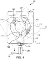
- the keys (120, 122 and 124) of the barrel portion 116 of adapter 110 and the keyways (220, 222 and 224) in the reception port 216 of base portion 210 are positioned so that in an initial aligned engagement position of the barrel portion 116 within the reception port 216 corresponds to the display device 10 having an orientation that is offset 30° clockwise from the landscape position display device. This is the only position in which the keys and keyways are aligned. In this position, the engagement shaft 254 of the plunger 250 is retracted so that the barrel portion 116 can rotate freely within the reception port 216 of the base portion 210.
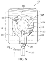
- FIG. 5 there is illustrated a view of the mounting assembly 100 when the display device 10 has been rotated into a landscape position.
- This position is advanced 30° in a clockwise direction from the orientation shown in Fig. 4 .
- the keys (120, 122 and 124) on the lower barrel section 116b of adapter portion 110 and the keyways (220, 222 and 224) in the reception port 216 of base portion 210 are rotated out of alignment.
- the engagement shaft 254 of the plunger 250 is advanced forward using the handle portion 256 so as to engage the radially inwardly extending recess 130 in the lower barrel section 116b, and thereby fix the position of the adapter portion 110 relative to the base portion 210.
- Fig. 6 there is illustrated a view of the mounting assembly 100 when the display device 10 has been rotated into a portrait position.
- This position is advanced 90° in a clockwise direction from the orientation shown in Fig. 5 , and 120° in a clockwise direction from the orientation shown in Fig. 5 .
- the keys (120, 122 and 124) on the lower barrel section 116b of adapter portion 110 and the keyways (220, 222 and 224) in the reception port 216 of base portion 210 are still out of alignment.
- the engagement shaft 254 of the plunger 250 is engaged in the radially inwardly extending recess 132 in the lower barrel section 116b, so as to fix the position of the adapter portion 110 relative to the base portion 210.
Description
- The subject invention relates to improvements in mounts for portable electronic displays, and more particularly, to a rotating adapter for mounting a portable electronic flight bag (EFB) on a supporting surface within the cockpit of an aircraft.
- An EFB is an electronic display device that a pilot may use for preflight check lists and similar activities. EFB's are generally handheld, portable devices that a pilot can take from flight to flight. Information about a pilot's flight may be preloaded onto the EFB so that the pilot can access it prior to, during and after the flight.
- In the past, a pilot may have simply placed an EFB loosely within the cockpit of an airplane, e.g., on the floor or on a console, which could lead to problems during the flight. For example, the EFB could become lost among other items in the cockpit, or the position of the EFB might shift during the flight. Further, if there is turbulence, the EFB could become damaged if it is not secured to a fixed surface within the cockpit.
- Partially in response to these concerns, the U.S. Federal Aviation Administration (FAA) has published guidelines designating three separate classes of EFB hardware approved for use under progressively more demanding conditions. Specifically, Class 1 devices are standard commercial-off-the-shelf (COTS) equipment such as laptops or handheld electronic devices. These devices are used as loose equipment and are typically stowed during critical phases of flight. A Class 1 EFB is considered a Portable Electronic Device (PED). These may connect to aircraft power and interface to other systems via certified (STC) docking station and/or power source. This would allow the Class 1 device to interface with other systems through the certified interface and other devices through an expansion port interface.
- Class 2 devices are also Portable Electronic Devices, and range from modified COTS equipment to purpose-built devices. They are typically mounted in the aircraft with the display being viewable to the pilot during all phases of flight. Mounts can include certified structural mounting devices or kneeboard devices. These devices may connect to aircraft power and data sources, e.g. through an ARINC 429 interface. A Class 2 EFB can be used for bi-directional data communication with other aircraft systems. In this class, a single line replaceable unit (LRU) would be an optimal solution based on the ease of installation and replacement.
- Class 3 devices are considered "installed equipment" and are subject to airworthiness requirements defined by the FAA. Unlike PEDs, these devices must be under design control. The hardware is subject to a limited number ofRTCA DO-160E requirements (for non-essential equipment--typical crash safety and Conducted and Radiated Emissions (EMC) testing). There may also be certain requirements for software. Class 3 EFBs are typically installed under STC or other airworthiness approval.
- Mounting brackets used for Class 2 and Class 3 hardware typically do not permit easy removal of the electronic equipment. The orientation and/or position of the electronic equipment also cannot be easily changed to accommodate user preference. Those mounting brackets that do permit adjustment, require considerable manipulation with both hands, which can be distracting and inconvenient for the pilot or other operator.
- It would be benefcial to provide a mounting assembly that allows for easy temporary installation of a Class 2 EFB on a supporting console within the cockpit of an aircraft without the use of any tools, fasteners or complicated moving parts.
-
US 5 870 642 discloses a panoramic support for a camera having a rotatable indexing head.US 2008/0251675 A1 discloses a rotating pedestal with an integrated locking mechanism. - The subject invention is directed to a new and useful assembly for mounting an electronic display device to a supporting structure, such as a console, within the cockpit of an aircraft, as defined in the appended claims. The assembly includes an adapter portion configured for attachment to a rear surface of the electronic display device and a base portion configured to be mounted to a fixed structure, such as a console, in the cockpit of the aircraft.
- The adapter portion of the mounting assembly has a mounting plate for securement to the rear surface of the display device with a plurality of fasteners, and a cylindrical barrel portion that extends away from the rear surface of the display device. The barrel portion may have three circumferentially disposed radially outwardly extending keys. The barrel portion further includes a first radially inwardly extending recess corresponding to a landscape position of the display device and a second radially inwardly extending recess corresponding to a portrait position of the display device.
- The base portion of the mounting assembly includes an upper surface or wall with a circular reception port formed therein for receiving the barrel of the adapter portion. The reception port may have three radially outwardly extending circumferentially disposed keyways formed therein for receiving the three corresponding keys formed on the barrel of the adapter portion.
- In addition, the mounting assembly includes a manually operated plunger operatively associated with the base portion for selectively engaging the first and second recesses in the barrel of the adapter portion to prevent relative rotation of the adapter portion and the base portion. A locking nut may also be provided for selectively securing the plunger in an engagement position relative to the base portion.
- Preferably, the three keys and keyways are positioned so that an initial engagement position of the barrel within the reception port corresponds to the display device having an orientation that is 30° clockwise from the landscape position of the display device and 120° clockwise from the portrait position of the display device.
- The barrel preferably includes a circumferential slot that is located axially above the three keys for engaging an annular retaining lip that surrounds the reception port in the upper surface of the base portion. The adapter portion may also include a plurality of spring loaded plungers retained in the barrel and mounted to bear against a bottom plate of the base portion to provide pressure against the retaining lip to add resistance against the rotation of the barrel within the reception port.
- These and other features of the mounting assembly of the subject invention and the manner in which it is employed within the cockpit of an aircraft will become more readily apparent to those having ordinary skill in the art from the following enabling description of the preferred embodiments of the subject invention taken in conjunction with the several drawings described below.
- So that those skilled in the art to which the subject invention appertains will readily understand how to make and use the mount assembly of the subject invention without undue experimentation, preferred embodiments thereof will be described in detail herein below by way of example only and with reference to certain figures, wherein:
-
Fig. 1 shows an electronic display device, in the form of an electronic flight bag, mounted on the console in the cockpit of an aircraft; -
Fig. 2 is an exploded perspective view of the mounting assembly of a preferred embodiment of the subject invention, with parts separated for ease of illustration, including an adapter portion configured for attachment to a rear surface of the electronic display device and a base portion configured to be mounted to the console in the cockpit of the aircraft; -
Fig. 3 is an exploded perspective view of the mounting assembly of a preferred embodiment of the subject invention, with parts separated for ease of illustration, and inverted from the view shown inFig. 2 ; -
Fig. 4 is a top plan view of the mounting assembly of a preferred embodiment of the subject invention, with the adapter portion disposed in an initial engaged position with respect to the base portion, so that the keys are aligned with the keyways and the display device is oriented 30° from its landscape position; -
Fig. 5 is a top plan view of the mounting assembly of a preferred embodiment of the subject invention, with the adapter portion rotated 30° in a clockwise direction relative to the base portion, so that the keys are out of alignment with the keyways, and the display device is oriented in its landscape position; and -
Fig. 6 is a top plan view of the mounting assembly of a preferred embodiment of the subject invention, with the adapter portion rotated 90° from the position shown inFig. 5 , in a clockwise direction relative to the base portion, so that the keys remain out of alignment with the keyways, and the display device is oriented in its portrait position. - Referring now to the drawings, wherein like reference numerals identify similar structural features or aspects of the subject invention, there is illustrated in
Fig. 1 anelectronic display device 10 that a pilot may use for preflight check lists and similar activities within the cockpit of an aircraft. - The
electronic display device 10 is removably mounted to a supporting structure orconsole 12 in the cockpit of an aircraft using the mounting assembly of the subject invention, which is described in greater detail herein below. The mounting assembly of the subject invention enables a pilot to easily and quickly mount theelectronic display device 10 to a supporting surface orconsole 12 in the cockpit of an aircraft without any tools, fasteners or latches. - Referring to
Fig. 2 and3 , there is shown the mounting assembly of a preferred embodiment of the subject invention, which is designated generally byreference numeral 100.Mounting assembly 100 includes two main components. These components include anadapter portion 110 configured for attachment to a rear surface of theelectronic display device 10 and abase portion 210 configured to be mounted to theconsole 12 or other fixed structure in the cockpit of an aircraft. - The
adapter portion 110 ofmounting assembly 100 has a mounting plate orflange 112 having a plurality ofapertures 114 formed therein. Theapertures 114 accommodate threaded fasteners (not shown) that are used to secure theadapter portion 110 to the rear surface of thedisplay device 10. Acylindrical barrel portion 116 depends from the undersurface of themounting plate 112 ofadapter portion 110. Thebarrel portion 116 includes anupper barrel section 116a having a first diameter and alower barrel section 116b having a second diameter that is less than that of theupper barrel section 116a. - The
lower section 116b of thebarrel portion 116 has three circumferentially disposed radially outwardly extending keys designated byreference numerals Figs. 2 and3 , the three keys are essentially similar in dimension and shape. It is envisioned however, that one or more of the keys can differ in size and/or shape from the other keys on thebarrel portion 116. However, it should be appreciated that at least one of the keys should be larger than the other keys and/or the keys should be unequally spaced apart from one another so that the keys do not drop into the keyways when thebarrel portion 116 is rotated within areception port 216 - It is also envisioned that different key arrangements can be provided by a manufacturer so that the
mounting assembly 100 may be customized for a particular aircraft or display device, or a skeleton key approach could be employed so that there is a single generic version of the mounting assembly. - The
lower section 116b ofbarrel portion 116 further includes two radially inwardly extendingrecesses recess 130 corresponds to a landscape mounting position of thedisplay device 10, as described in more detail below with respect toFig. 5 . The second radially inwardly extendingrecess 132 corresponds to a portrait mounting position of thedisplay device 10, as described in more detail below with reference toFig. 6 . It is envisioned that the arc between the tworecesses - The
base portion 210 of mountingassembly 100 includes an inclined upper surface ortop wall 212. Thecircular reception port 216 is formed within the inclinedupper surface 212 for receiving thebarrel portion 116 of theadapter 110. Thereception port 216 ofbase portion 210 has three radially outwardly extending circumferentially disposedkeyways keys lower barrel section 116b of theadapter portion 110, to rotatably and releasably mount thedisplay device 10 to thecockpit console 12, as shown inFig. 1 .Base portion 210 also includes aplurality mounting apertures 225 for accommodating fasteners (not shown) that secure the base portion to thecockpit console 12. - With continuing reference to
Figs. 2 and3 , mountingassembly 100 further includes a manually operatedplunger 250 for selectively engaging theadapter portion 110 to prevent relative rotation of theadapter position 110 and thebase portion 210 when thedisplay device 10 is in its landscape or portrait position. More particularly, theplunger 250 includes anengagement shaft 252 dimensioned and configured to selectively engage the radially inwardly extendingrecesses lower barrel section 116b ofbarrel portion 116. -
Plunger 250 further includes a threadedbody portion 254 for cooperating with a threadedbore 230 in thefront wall 232 ofbase portion 210. In addition,plunger 250 includes ahandle portion 256 for manually controlling the movement of theshaft 252 within thebody portion 210 relative to thebase portion 210. A lockingnut 260 cooperates with the threadedbody portion 254 ofplunger 250 for securing theplunger 250 relative to thebase portion 210. - As best seen in
Fig. 3 , the peripheral wall that surroundsreception port 216 defines a retaininglip 240. This retaininglip 240 rides within a gap that is formed between the upper surfaces ofkeys upper barrel section 116a ofbarrel portion 116. Three spring loadedpistons 150a-150c are retained inbores 152a-152c in thebarrel portion 116 to bear against acircular plate 270 secured to an interior surface of thetop wall 212 ofbase portion 210 by threadedfasteners 272 throughplate apertures 275. Thepistons 150a-150c are dimensioned and configured to urge the upper surfaces of thekeys lip 240 when the keys are rotated out of alignment with thekeyways barrel 116 within thereception port 216. Additionally, the spring loadedpistons 150a-150c serve to take up any inherent and necessary clearance within the assembly to minimize or otherwise eliminate rattle during vibratory loading while in use. - Referring to
Fig. 4 , the keys (120, 122 and 124) of thebarrel portion 116 ofadapter 110 and the keyways (220, 222 and 224) in thereception port 216 ofbase portion 210 are positioned so that in an initial aligned engagement position of thebarrel portion 116 within thereception port 216 corresponds to thedisplay device 10 having an orientation that is offset 30° clockwise from the landscape position display device. This is the only position in which the keys and keyways are aligned. In this position, theengagement shaft 254 of theplunger 250 is retracted so that thebarrel portion 116 can rotate freely within thereception port 216 of thebase portion 210. - Referring now to
Fig. 5 , there is illustrated a view of the mountingassembly 100 when thedisplay device 10 has been rotated into a landscape position. This position is advanced 30° in a clockwise direction from the orientation shown inFig. 4 . In this position, the keys (120, 122 and 124) on thelower barrel section 116b ofadapter portion 110 and the keyways (220, 222 and 224) in thereception port 216 ofbase portion 210 are rotated out of alignment. Furthermore, theengagement shaft 254 of theplunger 250 is advanced forward using thehandle portion 256 so as to engage the radially inwardly extendingrecess 130 in thelower barrel section 116b, and thereby fix the position of theadapter portion 110 relative to thebase portion 210. - Turning to
Fig. 6 , there is illustrated a view of the mountingassembly 100 when thedisplay device 10 has been rotated into a portrait position. This position is advanced 90° in a clockwise direction from the orientation shown inFig. 5 , and 120° in a clockwise direction from the orientation shown inFig. 5 . In this position, the keys (120, 122 and 124) on thelower barrel section 116b ofadapter portion 110 and the keyways (220, 222 and 224) in thereception port 216 ofbase portion 210 are still out of alignment. In addition, theengagement shaft 254 of theplunger 250 is engaged in the radially inwardly extendingrecess 132 in thelower barrel section 116b, so as to fix the position of theadapter portion 110 relative to thebase portion 210. - While the subject invention has been shown and described with reference to preferred embodiments, those skilled in the art will readily appreciate that various changes and/or modifications may be made thereto without departing from the scope of the subject invention as defined by the appended claims.
Claims (7)
- An assembly (100) for mounting an electronic display device (10) to a supporting structure (12) within the cockpit of an aircraft, comprising:a) an adapter portion (110) configured for attachment to a rear surface of an electronic display device, the adapter portion having a cylindrical barrel portion (116) extending away from the rear surface of the display device, the barrel portion having a first radially inwardly extending recess (130) corresponding to a landscape position of the display device and a second radially inwardly extending recess (132) corresponding to a portrait position of the display device;b) a base portion (210) configured for mounting to a fixed structure in the cockpit of an aircraft, the base portion including an upper surface (212) with a circular reception port (216) formed therein for receiving the barrel portion of the adapter plate; andc) a plunger (250) operatively associated with the base portion for selectively engaging the first and second recesses in the barrel portion of the adapter portion to prevent relative rotation of the adapter portion and the base portion;wherein the adapter portion (110) includes a mounting plate (112) for securement to the rear surface of the display device (10), and the barrel portion (116) extends from the mounting plate.
- An assembly (100) as recited in claim 1, wherein the barrel portion (116) includes a plurality of radially outwardly extending circumferentially disposed keys (120, 122, 124), and the reception port (216) includes a plurality of radially outwardly extending circumferentially disposed keyways (220, 222, 224) for receiving the plurality of keys on the barrel portion of the adapter portion (110).
- An assembly (100) as recited in Claim 2, wherein the plurality of keys (120, 122, 124) and corresponding keyways (220, 222, 224) are positioned so that an initial engagement position of the barrel portion (116) within the reception port (216) corresponds to the display device (10) having an orientation that is 30° clockwise from the landscape position of the display and 120° clockwise from the portrait position of the display device.
- An assembly (100) as recited in Claim 2 or 3, wherein the barrel (116) portion includes a circumferential slot located axially above the plurality of keys (120, 122, 124) for engaging an annular retaining lip (240) surrounding the reception bore (216) in the upper surface (212) of the base portion (210).
- An assembly (100) as recited in Claim 4, wherein the adapter portion (110) includes a plurality of spring loaded plungers (150a, 150b, 150c) mounted to bear against a bottom plate (270) of the base portion (210) to provide pressure against the retaining lip (240) to add resistance against rotation.
- An assembly (100) as recited in any preceding claim, further comprising a locking nut (260) for selectively securing the plunger (250) in an engagement position.
- An assembly (100) as recited in any of claims 2 to 6, wherein the barrel portion (116) comprises three circumferentially disposed keys (120, 122, 124) thereon, and the reception port (216) comprises three corresponding keyways (220, 222, 224) formed therein.
Applications Claiming Priority (1)
| Application Number | Priority Date | Filing Date | Title |
|---|---|---|---|
| US13/899,199 US8979048B2 (en) | 2013-05-21 | 2013-05-21 | Rotating electronic display adapter |
Publications (3)
| Publication Number | Publication Date |
|---|---|
| EP2808593A2 EP2808593A2 (en) | 2014-12-03 |
| EP2808593A3 EP2808593A3 (en) | 2014-12-10 |
| EP2808593B1 true EP2808593B1 (en) | 2017-08-23 |
Family
ID=50842047
Family Applications (1)
| Application Number | Title | Priority Date | Filing Date |
|---|---|---|---|
| EP14169346.5A Active EP2808593B1 (en) | 2013-05-21 | 2014-05-21 | Rotating electronic display adapter |
Country Status (5)
| Country | Link |
|---|---|
| US (1) | US8979048B2 (en) |
| EP (1) | EP2808593B1 (en) |
| CN (1) | CN104279415B (en) |
| BR (1) | BR102014012161B1 (en) |
| CA (1) | CA2852071C (en) |
Cited By (1)
| Publication number | Priority date | Publication date | Assignee | Title |
|---|---|---|---|---|
| FR3135704A1 (en) * | 2022-05-17 | 2023-11-24 | Dassault Aviation | Device for holding objects in an aircraft cabin and associated holding method |
Families Citing this family (8)
| Publication number | Priority date | Publication date | Assignee | Title |
|---|---|---|---|---|
| FR3000027B1 (en) * | 2012-12-21 | 2016-07-01 | Airbus | AIRCRAFT CONTROL UNIT WITH ADJUSTABLE ERGONOMIC DASHBOARD |
| US9335789B2 (en) * | 2013-05-10 | 2016-05-10 | Adam Merzon | System and apparatus for mounting a handheld electronic device |
| US9604580B2 (en) | 2015-06-19 | 2017-03-28 | Rosemount Aerospace, Inc. | Tool-less low profile rotation mount |
| US10492602B2 (en) * | 2017-01-26 | 2019-12-03 | Bose Corporation | Electronics enclosure mounting |
| USD837632S1 (en) | 2017-07-05 | 2019-01-08 | ACCO Brands Corporation | Lock |
| CN110285295B (en) * | 2019-07-11 | 2021-05-18 | 深圳利都科技有限公司 | High performance instrument and meter places fixing device |
| FR3106813A1 (en) * | 2020-02-03 | 2021-08-06 | Airbus Operations | KIT FOR AN AIRCRAFT CONTAINING A DASHBOARD AND A SUPPORT SYSTEM FOR A TOUCH TABLET |
| US11319731B1 (en) * | 2020-07-10 | 2022-05-03 | Vanguard Products Group, Inc. | Merchandise anti-theft device having a quick disconnect locking mechanism |
Family Cites Families (19)
| Publication number | Priority date | Publication date | Assignee | Title |
|---|---|---|---|---|
| US2720372A (en) * | 1953-05-22 | 1955-10-11 | Gordon D Gowan | Swivel adapter for mounting a camera on a tripod |
| US4566664A (en) * | 1984-06-04 | 1986-01-28 | Donald Jimmie W | Rotatable mounting unit |
| US4570892A (en) | 1984-12-11 | 1986-02-18 | Zenith Electronics Corporation | Tiltable rotating display monitor mount |
| US4946127A (en) * | 1990-01-12 | 1990-08-07 | Ark International, Inc. | Theft resistant rotatable mount for computer consoles and the like |
| US5626435A (en) * | 1993-10-29 | 1997-05-06 | Rockinger Spezialfabrik Fur Anhangerkupplungen Gmbh & Co. | Coupling assembly |
| US5870642A (en) * | 1997-08-13 | 1999-02-09 | Eastman Kodak Company | Panoramic support for camera permits horizontal-format and vertical-format image recordings |
| JP2002311845A (en) * | 2001-04-16 | 2002-10-25 | Fujitsu Ltd | Display device |
| US6588719B1 (en) * | 2002-09-10 | 2003-07-08 | Hollingsead International, Inc. | Mounting and support bracket |
| DE202004015006U1 (en) * | 2004-09-27 | 2004-12-23 | Müller, Jochen, Dr. | Mounting device for a tripod on a camera |
| US7686250B2 (en) | 2006-01-20 | 2010-03-30 | Fortes Hugo L | Electronic display mount |
| TWM307256U (en) | 2006-08-16 | 2007-03-01 | Jarllytec Co Ltd | Fastening structure with rapid stevedoring features |
| US7303171B1 (en) | 2006-11-21 | 2007-12-04 | Supa Technology Co., Ltd. | Adjustable fixing mount |
| US7644903B2 (en) * | 2007-01-19 | 2010-01-12 | Metra Electronics | Rotating pedestal with lock |
| CN201278621Y (en) | 2008-08-29 | 2009-07-22 | 鸿富锦精密工业(深圳)有限公司 | Sliding turnover type electronic apparatus |
| US8215583B2 (en) | 2008-09-22 | 2012-07-10 | Pentastar Aviation, Inc. | Articulating yoke mount |
| US8308114B2 (en) * | 2009-02-25 | 2012-11-13 | Tensolite LLC | Electronic flight bag mounting bracket |
| US20100301080A1 (en) * | 2009-05-28 | 2010-12-02 | Tom Heckman | Pivot mount assembly |
| US8701953B2 (en) * | 2009-10-09 | 2014-04-22 | Raytheon Company | Electronic flight bag mounting system |
| US8870143B2 (en) * | 2012-02-21 | 2014-10-28 | Dmitry Kubin | Low profile secure asymmetrical turn-lock coupling mechanism with magnetic rotational orientation locks |
-
2013
- 2013-05-21 US US13/899,199 patent/US8979048B2/en active Active
-
2014
- 2014-05-20 CA CA2852071A patent/CA2852071C/en active Active
- 2014-05-20 BR BR102014012161-7A patent/BR102014012161B1/en active IP Right Grant
- 2014-05-21 EP EP14169346.5A patent/EP2808593B1/en active Active
- 2014-05-21 CN CN201410215135.XA patent/CN104279415B/en active Active
Non-Patent Citations (1)
| Title |
|---|
| None * |
Cited By (1)
| Publication number | Priority date | Publication date | Assignee | Title |
|---|---|---|---|---|
| FR3135704A1 (en) * | 2022-05-17 | 2023-11-24 | Dassault Aviation | Device for holding objects in an aircraft cabin and associated holding method |
Also Published As
| Publication number | Publication date |
|---|---|
| BR102014012161B1 (en) | 2021-07-27 |
| CN104279415B (en) | 2018-09-11 |
| CN104279415A (en) | 2015-01-14 |
| CA2852071C (en) | 2020-11-24 |
| US20140346296A1 (en) | 2014-11-27 |
| US8979048B2 (en) | 2015-03-17 |
| CA2852071A1 (en) | 2014-11-21 |
| EP2808593A2 (en) | 2014-12-03 |
| BR102014012161A2 (en) | 2018-11-21 |
| EP2808593A3 (en) | 2014-12-10 |
Similar Documents
| Publication | Publication Date | Title |
|---|---|---|
| EP2808593B1 (en) | Rotating electronic display adapter | |
| US9027892B2 (en) | Rotating electronic display mount | |
| EP2401199B1 (en) | Electronic flight bag mounting bracket | |
| EP2569187B1 (en) | Coupling assembly | |
| EP2673549B1 (en) | Tablet holder and tablet stowage system | |
| US9457905B2 (en) | Vehicle seat comprising integrated holder for electronic devices | |
| EP2947370B1 (en) | Display mounting apparatus | |
| US20110101058A1 (en) | Pivot mount assembly | |
| US8701953B2 (en) | Electronic flight bag mounting system | |
| US20130193290A1 (en) | Low-profile quick-adjust mount for laptop computer | |
| US20120248833A1 (en) | Seatback holder for tablet computers | |
| US10252803B2 (en) | Securing system, retaining device and portable mounting adapter for passenger appliances in an aircraft | |
| US20100301080A1 (en) | Pivot mount assembly | |
| US10520128B2 (en) | Touch screen tablet holder for aircraft yoke assembly | |
| BR102014011496B1 (en) | ASSEMBLY FOR MOUNTING AN ELECTRONIC DISPLAY DEVICE TO A SUPPORT STRUCTURE INSIDE THE COCKPIT OF AN AIRCRAFT | |
| US20100301185A1 (en) | Pivot mount assembly |
Legal Events
| Date | Code | Title | Description |
|---|---|---|---|
| PUAL | Search report despatched |
Free format text: ORIGINAL CODE: 0009013 |
|
| PUAI | Public reference made under article 153(3) epc to a published international application that has entered the european phase |
Free format text: ORIGINAL CODE: 0009012 |
|
| 17P | Request for examination filed |
Effective date: 20140521 |
|
| AK | Designated contracting states |
Kind code of ref document: A2 Designated state(s): AL AT BE BG CH CY CZ DE DK EE ES FI FR GB GR HR HU IE IS IT LI LT LU LV MC MK MT NL NO PL PT RO RS SE SI SK SM TR |
|
| AX | Request for extension of the european patent |
Extension state: BA ME |
|
| AK | Designated contracting states |
Kind code of ref document: A3 Designated state(s): AL AT BE BG CH CY CZ DE DK EE ES FI FR GB GR HR HU IE IS IT LI LT LU LV MC MK MT NL NO PL PT RO RS SE SI SK SM TR |
|
| AX | Request for extension of the european patent |
Extension state: BA ME |
|
| RIC1 | Information provided on ipc code assigned before grant |
Ipc: B64D 43/00 20060101ALI20141104BHEP Ipc: F16M 11/08 20060101ALI20141104BHEP Ipc: F16M 11/04 20060101AFI20141104BHEP Ipc: F16M 13/02 20060101ALI20141104BHEP |
|
| R17P | Request for examination filed (corrected) |
Effective date: 20150610 |
|
| RBV | Designated contracting states (corrected) |
Designated state(s): AL AT BE BG CH CY CZ DE DK EE ES FI FR GB GR HR HU IE IS IT LI LT LU LV MC MK MT NL NO PL PT RO RS SE SI SK SM TR |
|
| 17Q | First examination report despatched |
Effective date: 20160621 |
|
| GRAP | Despatch of communication of intention to grant a patent |
Free format text: ORIGINAL CODE: EPIDOSNIGR1 |
|
| INTG | Intention to grant announced |
Effective date: 20161215 |
|
| GRAS | Grant fee paid |
Free format text: ORIGINAL CODE: EPIDOSNIGR3 |
|
| GRAJ | Information related to disapproval of communication of intention to grant by the applicant or resumption of examination proceedings by the epo deleted |
Free format text: ORIGINAL CODE: EPIDOSDIGR1 |
|
| GRAL | Information related to payment of fee for publishing/printing deleted |
Free format text: ORIGINAL CODE: EPIDOSDIGR3 |
|
| INTC | Intention to grant announced (deleted) | ||
| GRAR | Information related to intention to grant a patent recorded |
Free format text: ORIGINAL CODE: EPIDOSNIGR71 |
|
| GRAA | (expected) grant |
Free format text: ORIGINAL CODE: 0009210 |
|
| INTG | Intention to grant announced |
Effective date: 20170712 |
|
| AK | Designated contracting states |
Kind code of ref document: B1 Designated state(s): AL AT BE BG CH CY CZ DE DK EE ES FI FR GB GR HR HU IE IS IT LI LT LU LV MC MK MT NL NO PL PT RO RS SE SI SK SM TR |
|
| REG | Reference to a national code |
Ref country code: GB Ref legal event code: FG4D |
|
| REG | Reference to a national code |
Ref country code: CH Ref legal event code: EP |
|
| REG | Reference to a national code |
Ref country code: AT Ref legal event code: REF Ref document number: 921723 Country of ref document: AT Kind code of ref document: T Effective date: 20170915 |
|
| REG | Reference to a national code |
Ref country code: IE Ref legal event code: FG4D |
|
| REG | Reference to a national code |
Ref country code: DE Ref legal event code: R096 Ref document number: 602014013384 Country of ref document: DE |
|
| REG | Reference to a national code |
Ref country code: NL Ref legal event code: MP Effective date: 20170823 |
|
| REG | Reference to a national code |
Ref country code: LT Ref legal event code: MG4D |
|
| REG | Reference to a national code |
Ref country code: AT Ref legal event code: MK05 Ref document number: 921723 Country of ref document: AT Kind code of ref document: T Effective date: 20170823 |
|
| PG25 | Lapsed in a contracting state [announced via postgrant information from national office to epo] |
Ref country code: SE Free format text: LAPSE BECAUSE OF FAILURE TO SUBMIT A TRANSLATION OF THE DESCRIPTION OR TO PAY THE FEE WITHIN THE PRESCRIBED TIME-LIMIT Effective date: 20170823 Ref country code: FI Free format text: LAPSE BECAUSE OF FAILURE TO SUBMIT A TRANSLATION OF THE DESCRIPTION OR TO PAY THE FEE WITHIN THE PRESCRIBED TIME-LIMIT Effective date: 20170823 Ref country code: HR Free format text: LAPSE BECAUSE OF FAILURE TO SUBMIT A TRANSLATION OF THE DESCRIPTION OR TO PAY THE FEE WITHIN THE PRESCRIBED TIME-LIMIT Effective date: 20170823 Ref country code: AT Free format text: LAPSE BECAUSE OF FAILURE TO SUBMIT A TRANSLATION OF THE DESCRIPTION OR TO PAY THE FEE WITHIN THE PRESCRIBED TIME-LIMIT Effective date: 20170823 Ref country code: NL Free format text: LAPSE BECAUSE OF FAILURE TO SUBMIT A TRANSLATION OF THE DESCRIPTION OR TO PAY THE FEE WITHIN THE PRESCRIBED TIME-LIMIT Effective date: 20170823 Ref country code: LT Free format text: LAPSE BECAUSE OF FAILURE TO SUBMIT A TRANSLATION OF THE DESCRIPTION OR TO PAY THE FEE WITHIN THE PRESCRIBED TIME-LIMIT Effective date: 20170823 Ref country code: NO Free format text: LAPSE BECAUSE OF FAILURE TO SUBMIT A TRANSLATION OF THE DESCRIPTION OR TO PAY THE FEE WITHIN THE PRESCRIBED TIME-LIMIT Effective date: 20171123 |
|
| PG25 | Lapsed in a contracting state [announced via postgrant information from national office to epo] |
Ref country code: RS Free format text: LAPSE BECAUSE OF FAILURE TO SUBMIT A TRANSLATION OF THE DESCRIPTION OR TO PAY THE FEE WITHIN THE PRESCRIBED TIME-LIMIT Effective date: 20170823 Ref country code: GR Free format text: LAPSE BECAUSE OF FAILURE TO SUBMIT A TRANSLATION OF THE DESCRIPTION OR TO PAY THE FEE WITHIN THE PRESCRIBED TIME-LIMIT Effective date: 20171124 Ref country code: ES Free format text: LAPSE BECAUSE OF FAILURE TO SUBMIT A TRANSLATION OF THE DESCRIPTION OR TO PAY THE FEE WITHIN THE PRESCRIBED TIME-LIMIT Effective date: 20170823 Ref country code: BG Free format text: LAPSE BECAUSE OF FAILURE TO SUBMIT A TRANSLATION OF THE DESCRIPTION OR TO PAY THE FEE WITHIN THE PRESCRIBED TIME-LIMIT Effective date: 20171123 Ref country code: LV Free format text: LAPSE BECAUSE OF FAILURE TO SUBMIT A TRANSLATION OF THE DESCRIPTION OR TO PAY THE FEE WITHIN THE PRESCRIBED TIME-LIMIT Effective date: 20170823 Ref country code: PL Free format text: LAPSE BECAUSE OF FAILURE TO SUBMIT A TRANSLATION OF THE DESCRIPTION OR TO PAY THE FEE WITHIN THE PRESCRIBED TIME-LIMIT Effective date: 20170823 Ref country code: IS Free format text: LAPSE BECAUSE OF FAILURE TO SUBMIT A TRANSLATION OF THE DESCRIPTION OR TO PAY THE FEE WITHIN THE PRESCRIBED TIME-LIMIT Effective date: 20171223 |
|
| REG | Reference to a national code |
Ref country code: FR Ref legal event code: PLFP Year of fee payment: 5 |
|
| PG25 | Lapsed in a contracting state [announced via postgrant information from national office to epo] |
Ref country code: CZ Free format text: LAPSE BECAUSE OF FAILURE TO SUBMIT A TRANSLATION OF THE DESCRIPTION OR TO PAY THE FEE WITHIN THE PRESCRIBED TIME-LIMIT Effective date: 20170823 Ref country code: RO Free format text: LAPSE BECAUSE OF FAILURE TO SUBMIT A TRANSLATION OF THE DESCRIPTION OR TO PAY THE FEE WITHIN THE PRESCRIBED TIME-LIMIT Effective date: 20170823 Ref country code: DK Free format text: LAPSE BECAUSE OF FAILURE TO SUBMIT A TRANSLATION OF THE DESCRIPTION OR TO PAY THE FEE WITHIN THE PRESCRIBED TIME-LIMIT Effective date: 20170823 |
|
| REG | Reference to a national code |
Ref country code: DE Ref legal event code: R097 Ref document number: 602014013384 Country of ref document: DE |
|
| PG25 | Lapsed in a contracting state [announced via postgrant information from national office to epo] |
Ref country code: SM Free format text: LAPSE BECAUSE OF FAILURE TO SUBMIT A TRANSLATION OF THE DESCRIPTION OR TO PAY THE FEE WITHIN THE PRESCRIBED TIME-LIMIT Effective date: 20170823 Ref country code: EE Free format text: LAPSE BECAUSE OF FAILURE TO SUBMIT A TRANSLATION OF THE DESCRIPTION OR TO PAY THE FEE WITHIN THE PRESCRIBED TIME-LIMIT Effective date: 20170823 Ref country code: SK Free format text: LAPSE BECAUSE OF FAILURE TO SUBMIT A TRANSLATION OF THE DESCRIPTION OR TO PAY THE FEE WITHIN THE PRESCRIBED TIME-LIMIT Effective date: 20170823 Ref country code: IT Free format text: LAPSE BECAUSE OF FAILURE TO SUBMIT A TRANSLATION OF THE DESCRIPTION OR TO PAY THE FEE WITHIN THE PRESCRIBED TIME-LIMIT Effective date: 20170823 |
|
| PLBE | No opposition filed within time limit |
Free format text: ORIGINAL CODE: 0009261 |
|
| STAA | Information on the status of an ep patent application or granted ep patent |
Free format text: STATUS: NO OPPOSITION FILED WITHIN TIME LIMIT |
|
| 26N | No opposition filed |
Effective date: 20180524 |
|
| PG25 | Lapsed in a contracting state [announced via postgrant information from national office to epo] |
Ref country code: SI Free format text: LAPSE BECAUSE OF FAILURE TO SUBMIT A TRANSLATION OF THE DESCRIPTION OR TO PAY THE FEE WITHIN THE PRESCRIBED TIME-LIMIT Effective date: 20170823 |
|
| REG | Reference to a national code |
Ref country code: CH Ref legal event code: PL |
|
| REG | Reference to a national code |
Ref country code: BE Ref legal event code: MM Effective date: 20180531 |
|
| PG25 | Lapsed in a contracting state [announced via postgrant information from national office to epo] |
Ref country code: MC Free format text: LAPSE BECAUSE OF FAILURE TO SUBMIT A TRANSLATION OF THE DESCRIPTION OR TO PAY THE FEE WITHIN THE PRESCRIBED TIME-LIMIT Effective date: 20170823 |
|
| REG | Reference to a national code |
Ref country code: IE Ref legal event code: MM4A |
|
| PG25 | Lapsed in a contracting state [announced via postgrant information from national office to epo] |
Ref country code: CH Free format text: LAPSE BECAUSE OF NON-PAYMENT OF DUE FEES Effective date: 20180531 Ref country code: LI Free format text: LAPSE BECAUSE OF NON-PAYMENT OF DUE FEES Effective date: 20180531 |
|
| PG25 | Lapsed in a contracting state [announced via postgrant information from national office to epo] |
Ref country code: LU Free format text: LAPSE BECAUSE OF NON-PAYMENT OF DUE FEES Effective date: 20180521 |
|
| PG25 | Lapsed in a contracting state [announced via postgrant information from national office to epo] |
Ref country code: IE Free format text: LAPSE BECAUSE OF NON-PAYMENT OF DUE FEES Effective date: 20180521 |
|
| PG25 | Lapsed in a contracting state [announced via postgrant information from national office to epo] |
Ref country code: BE Free format text: LAPSE BECAUSE OF NON-PAYMENT OF DUE FEES Effective date: 20180531 |
|
| PG25 | Lapsed in a contracting state [announced via postgrant information from national office to epo] |
Ref country code: MT Free format text: LAPSE BECAUSE OF NON-PAYMENT OF DUE FEES Effective date: 20180521 |
|
| PG25 | Lapsed in a contracting state [announced via postgrant information from national office to epo] |
Ref country code: TR Free format text: LAPSE BECAUSE OF FAILURE TO SUBMIT A TRANSLATION OF THE DESCRIPTION OR TO PAY THE FEE WITHIN THE PRESCRIBED TIME-LIMIT Effective date: 20170823 |
|
| PG25 | Lapsed in a contracting state [announced via postgrant information from national office to epo] |
Ref country code: PT Free format text: LAPSE BECAUSE OF FAILURE TO SUBMIT A TRANSLATION OF THE DESCRIPTION OR TO PAY THE FEE WITHIN THE PRESCRIBED TIME-LIMIT Effective date: 20170823 Ref country code: HU Free format text: LAPSE BECAUSE OF FAILURE TO SUBMIT A TRANSLATION OF THE DESCRIPTION OR TO PAY THE FEE WITHIN THE PRESCRIBED TIME-LIMIT; INVALID AB INITIO Effective date: 20140521 |
|
| PG25 | Lapsed in a contracting state [announced via postgrant information from national office to epo] |
Ref country code: MK Free format text: LAPSE BECAUSE OF NON-PAYMENT OF DUE FEES Effective date: 20170823 Ref country code: CY Free format text: LAPSE BECAUSE OF FAILURE TO SUBMIT A TRANSLATION OF THE DESCRIPTION OR TO PAY THE FEE WITHIN THE PRESCRIBED TIME-LIMIT Effective date: 20170823 |
|
| PG25 | Lapsed in a contracting state [announced via postgrant information from national office to epo] |
Ref country code: AL Free format text: LAPSE BECAUSE OF FAILURE TO SUBMIT A TRANSLATION OF THE DESCRIPTION OR TO PAY THE FEE WITHIN THE PRESCRIBED TIME-LIMIT Effective date: 20170823 |
|
| PGFP | Annual fee paid to national office [announced via postgrant information from national office to epo] |
Ref country code: FR Payment date: 20230420 Year of fee payment: 10 Ref country code: DE Payment date: 20230419 Year of fee payment: 10 |
|
| PGFP | Annual fee paid to national office [announced via postgrant information from national office to epo] |
Ref country code: GB Payment date: 20230420 Year of fee payment: 10 |