EP2947298A1 - Internal-combustion-engine control device and control method - Google Patents
Internal-combustion-engine control device and control method Download PDFInfo
- Publication number
- EP2947298A1 EP2947298A1 EP13871586.7A EP13871586A EP2947298A1 EP 2947298 A1 EP2947298 A1 EP 2947298A1 EP 13871586 A EP13871586 A EP 13871586A EP 2947298 A1 EP2947298 A1 EP 2947298A1
- Authority
- EP
- European Patent Office
- Prior art keywords
- compression ratio
- variable
- variable compression
- ratio mechanism
- fuel cut
- Prior art date
- Legal status (The legal status is an assumption and is not a legal conclusion. Google has not performed a legal analysis and makes no representation as to the accuracy of the status listed.)
- Granted
Links
Images

Classifications
-
- F—MECHANICAL ENGINEERING; LIGHTING; HEATING; WEAPONS; BLASTING
- F02—COMBUSTION ENGINES; HOT-GAS OR COMBUSTION-PRODUCT ENGINE PLANTS
- F02D—CONTROLLING COMBUSTION ENGINES
- F02D41/00—Electrical control of supply of combustible mixture or its constituents
- F02D41/22—Safety or indicating devices for abnormal conditions
-
- F—MECHANICAL ENGINEERING; LIGHTING; HEATING; WEAPONS; BLASTING
- F02—COMBUSTION ENGINES; HOT-GAS OR COMBUSTION-PRODUCT ENGINE PLANTS
- F02B—INTERNAL-COMBUSTION PISTON ENGINES; COMBUSTION ENGINES IN GENERAL
- F02B75/00—Other engines
- F02B75/04—Engines with variable distances between pistons at top dead-centre positions and cylinder heads
- F02B75/045—Engines with variable distances between pistons at top dead-centre positions and cylinder heads by means of a variable connecting rod length
-
- F—MECHANICAL ENGINEERING; LIGHTING; HEATING; WEAPONS; BLASTING
- F02—COMBUSTION ENGINES; HOT-GAS OR COMBUSTION-PRODUCT ENGINE PLANTS
- F02D—CONTROLLING COMBUSTION ENGINES
- F02D41/00—Electrical control of supply of combustible mixture or its constituents
- F02D41/0002—Controlling intake air
- F02D41/0005—Controlling intake air during deceleration
-
- F—MECHANICAL ENGINEERING; LIGHTING; HEATING; WEAPONS; BLASTING
- F02—COMBUSTION ENGINES; HOT-GAS OR COMBUSTION-PRODUCT ENGINE PLANTS
- F02D—CONTROLLING COMBUSTION ENGINES
- F02D41/00—Electrical control of supply of combustible mixture or its constituents
- F02D41/02—Circuit arrangements for generating control signals
- F02D41/04—Introducing corrections for particular operating conditions
- F02D41/12—Introducing corrections for particular operating conditions for deceleration
- F02D41/123—Introducing corrections for particular operating conditions for deceleration the fuel injection being cut-off
-
- F—MECHANICAL ENGINEERING; LIGHTING; HEATING; WEAPONS; BLASTING
- F02—COMBUSTION ENGINES; HOT-GAS OR COMBUSTION-PRODUCT ENGINE PLANTS
- F02D—CONTROLLING COMBUSTION ENGINES
- F02D41/00—Electrical control of supply of combustible mixture or its constituents
- F02D41/22—Safety or indicating devices for abnormal conditions
- F02D41/221—Safety or indicating devices for abnormal conditions relating to the failure of actuators or electrically driven elements
-
- F—MECHANICAL ENGINEERING; LIGHTING; HEATING; WEAPONS; BLASTING
- F02—COMBUSTION ENGINES; HOT-GAS OR COMBUSTION-PRODUCT ENGINE PLANTS
- F02D—CONTROLLING COMBUSTION ENGINES
- F02D41/00—Electrical control of supply of combustible mixture or its constituents
- F02D41/30—Controlling fuel injection
- F02D41/3011—Controlling fuel injection according to or using specific or several modes of combustion
- F02D41/3076—Controlling fuel injection according to or using specific or several modes of combustion with special conditions for selecting a mode of combustion, e.g. for starting, for diagnosing
-
- F—MECHANICAL ENGINEERING; LIGHTING; HEATING; WEAPONS; BLASTING
- F02—COMBUSTION ENGINES; HOT-GAS OR COMBUSTION-PRODUCT ENGINE PLANTS
- F02D—CONTROLLING COMBUSTION ENGINES
- F02D13/00—Controlling the engine output power by varying inlet or exhaust valve operating characteristics, e.g. timing
- F02D13/02—Controlling the engine output power by varying inlet or exhaust valve operating characteristics, e.g. timing during engine operation
- F02D13/0203—Variable control of intake and exhaust valves
- F02D13/0207—Variable control of intake and exhaust valves changing valve lift or valve lift and timing
-
- F—MECHANICAL ENGINEERING; LIGHTING; HEATING; WEAPONS; BLASTING
- F02—COMBUSTION ENGINES; HOT-GAS OR COMBUSTION-PRODUCT ENGINE PLANTS
- F02D—CONTROLLING COMBUSTION ENGINES
- F02D15/00—Varying compression ratio
- F02D15/02—Varying compression ratio by alteration or displacement of piston stroke
-
- F—MECHANICAL ENGINEERING; LIGHTING; HEATING; WEAPONS; BLASTING
- F02—COMBUSTION ENGINES; HOT-GAS OR COMBUSTION-PRODUCT ENGINE PLANTS
- F02D—CONTROLLING COMBUSTION ENGINES
- F02D41/00—Electrical control of supply of combustible mixture or its constituents
- F02D41/0002—Controlling intake air
- F02D2041/001—Controlling intake air for engines with variable valve actuation
-
- F—MECHANICAL ENGINEERING; LIGHTING; HEATING; WEAPONS; BLASTING
- F02—COMBUSTION ENGINES; HOT-GAS OR COMBUSTION-PRODUCT ENGINE PLANTS
- F02D—CONTROLLING COMBUSTION ENGINES
- F02D41/00—Electrical control of supply of combustible mixture or its constituents
- F02D41/0002—Controlling intake air
- F02D2041/002—Controlling intake air by simultaneous control of throttle and variable valve actuation
-
- F—MECHANICAL ENGINEERING; LIGHTING; HEATING; WEAPONS; BLASTING
- F02—COMBUSTION ENGINES; HOT-GAS OR COMBUSTION-PRODUCT ENGINE PLANTS
- F02D—CONTROLLING COMBUSTION ENGINES
- F02D41/00—Electrical control of supply of combustible mixture or its constituents
- F02D41/22—Safety or indicating devices for abnormal conditions
- F02D2041/227—Limping Home, i.e. taking specific engine control measures at abnormal conditions
-
- Y—GENERAL TAGGING OF NEW TECHNOLOGICAL DEVELOPMENTS; GENERAL TAGGING OF CROSS-SECTIONAL TECHNOLOGIES SPANNING OVER SEVERAL SECTIONS OF THE IPC; TECHNICAL SUBJECTS COVERED BY FORMER USPC CROSS-REFERENCE ART COLLECTIONS [XRACs] AND DIGESTS
- Y02—TECHNOLOGIES OR APPLICATIONS FOR MITIGATION OR ADAPTATION AGAINST CLIMATE CHANGE
- Y02T—CLIMATE CHANGE MITIGATION TECHNOLOGIES RELATED TO TRANSPORTATION
- Y02T10/00—Road transport of goods or passengers
- Y02T10/10—Internal combustion engine [ICE] based vehicles
- Y02T10/40—Engine management systems
Definitions
- the present invention relates generally to an internal combustion engine which includes a variable compression ratio mechanism configured to vary a mechanical compression ratio by varying a positional relationship between a piston and a cylinder, and particularly to a control apparatus and a control method for performing an operation against a failure in a drive mechanism of the variable compression ratio mechanism.
- variable compression ratio mechanisms In the technical field of internal combustion engine, various types of variable compression ratio mechanisms have been known. For example, many variable compression ratio mechanisms have been proposed by the present applicant and others, in which a piston top dead center position is displaced vertically by varying a link geometry of a multi-link type piston crank mechanism. Patent documents 1 and 2 describe variable compression ratio mechanisms in which a mechanical compression ratio is varied by vertical displacement of a cylinder with respect to a central position of a crankshaft.
- variable compression ratio mechanism when a drive mechanism for varying the compression ratio is failed, it may become impossible to control the compression ratio, so that the compression ratio may become higher than intended.
- patent document 1 discloses adding a hydraulic circuit for abnormal condition, in a configuration that a cylinder side and a crank case side are configured to be moved relative to each other by a hydraulic drive mechanism.
- the hydraulic circuit for abnormal condition is configured to guide working oil between two hydraulic chambers, to allow the compression ratio to vary only to a lower compression ratio side, when the hydraulic drive mechanism is abnormal.
- Patent document 2 discloses a variable compression ratio mechanism employing an electric motor as a drive mechanism, in which a helical torsion coil spring is provided to apply a force to bias the variable compression ratio mechanism toward the lower compression ratio side.
- the biasing force becomes maximized, when the compression ratio is maximized.
- the variable compression ratio mechanism is promoted to return to a low compression ratio state by the biasing force of the helical torsion coil spring.
- an internal combustion engine control apparatus comprises: a variable compression ratio mechanism configured to vary a mechanical compression ratio by varying a positional relationship between a piston and a cylinder; a fuel cut means configured to perform a fuel cut in a predetermined decelerating state; a failure detecting means configured to detect a failure in the variable compression ratio mechanism; and a failed-state control means configured to perform at least one of first and second operations, while the fuel cut is being carried out by the fuel cut means under condition that the variable compression ratio mechanism is failed, wherein the first operation is to set lower an in-cylinder negative pressure during suction stroke than while the fuel cut is being performed under condition that the variable compression ratio mechanism is normal, and wherein the second operation is to set higher an in-cylinder positive pressure during compression stroke to expansion stroke than while the fuel cut is being performed under condition that the variable compression ratio mechanism is normal.
- the in-cylinder pressure during suction stroke is a negative pressure, but the in-cylinder pressure thereafter becomes high due to combustion pressure, so that the combustion pressure acts on the piston and a ceiling wall surface of a combustion chamber, and the variable compression ratio mechanism is biased basically in a direction to increase volumetric capacity of the combustion chamber, namely, in a direction to reduce the compression ratio. Accordingly, the compression ratio decreases gradually, even in a situation where the variable compression ratio mechanism fails to be actively controlled, due to some failure.
- the in-cylinder pressure during suction stroke is a negative pressure, and a condition is dominant where the negative pressure acts on the piston and the ceiling wall surface of the combustion chamber, so that the variable compression ratio mechanism may be shifted toward the higher compression ratio side.
- the in-cylinder negative pressure during suction stroke is set lower when the fuel cut is being operated, than under a condition that the variable compression ratio mechanism is normal. This suppresses the negative pressure from shifting the variable compression ratio mechanism toward the higher compression ratio side. Moreover, the increase of the in-cylinder positive pressure during compression stroke to expansion stroke acts in the direction to expand the volumetric capacity of the combustion chamber, and thereby suppresses the variable compression ratio mechanism from shifting toward the higher compression ratio side.
- variable compression ratio mechanism it is possible to suppress the variable compression ratio mechanism from shifting toward the higher compression ratio side due to fuel cut operation, when the variable compression ratio mechanism is failed.
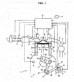
- FIG. 1 shows system configuration of an automotive internal combustion engine 1 to which the present invention is applied.
- internal combustion engine 1 is a four-stroke cycle, spark-ignition type internal combustion engine which is provided with a variable compression ratio mechanism 2 which employs a multi-link type piston crank mechanism.
- a pair of intake valves 4 and a pair of exhaust valves 5 are arranged at a ceiling wall surface of each cylinder 3, and an ignition plug 6 is arranged at a central portion surrounded by intake valves 4 and exhaust valves 5.
- Intake valves 4 are provided with an intake-side variable valve mechanism 7 configured to control opening and closing timings of intake valves 4 variably.
- Exhaust valves 5 are provided with an exhaust-side variable valve mechanism 8 configured to control opening and closing timings of exhaust valves 5 variably.
- Variable valve mechanisms 7, 8 may be configured to vary the opening timing and the closing timing independently from each other, or may be configured to advance and retard the opening timing and the closing timing simultaneously with each other.
- the present embodiment employs the latter type, which is configured to advance and retard the phase of a camshaft.
- a fuel injection valve 11 is provided per cylinder and arranged in an intake air passage 10 that is connected to a combustion chamber 9 via intake valves 4.
- An electronically controlled throttle valve 14 is disposed upstream of an intake air collector 12 in intake air passage 10, wherein the opening of throttle valve 14 is controlled based on a control signal from an engine controller 13.
- An air flow meter 15 is disposed further upstream of throttle valve 14, wherein air flow meter 15 senses an intake air quantity.
- a catalytic device 17 is disposed in an exhaust gas passage 16 that is connected to combustion chamber 9 via exhaust valves 5, wherein catalytic device 17 is composed of a three-way catalyst.
- An air fuel ratio sensor 18 is disposed upstream of catalytic device 17 for sensing the air-fuel ratio.
- Engine controller 13 receives input of sensing signals from sensors, such as air flow meter 15, air fuel ratio sensor 18, a crank angle sensor 19 for sensing the engine rotational speed, a water temperature sensor 20 for sensing the temperature of cooling water, and an accelerator opening sensor 21 for sensing the amount of depression of an accelerator pedal operated by a driver. Based on the sensing signals, engine controller 13 optimally controls the fuel injection quantity and injection timing of fuel injection valve 11, the ignition timing of ignition plug 6, the opening and closing timings of intake valves 4 and exhaust valves 5, the opening of throttle valve 14, and others.
- variable compression ratio mechanism 2 employs a known multi-link type piston crank mechanism as disclosed by JP 2004-116434 A .
- Variable compression ratio mechanism 2 generally includes: a lower link 22 that is rotatably supported by a crank pin 21a of a crankshaft 21; an upper link 25 that links an upper pin 23 at a first end portion of lower link 22 and a piston pin 24a of a piston 24 to each other; a control link 27 that includes a first end connected to a control pin 26 at a second end portion of lower link 22; and a control shaft 28 that supports a second end of control link 27 for allowing swinging motion of control link 27.
- Crankshaft 21 and control shaft 28 are rotatably supported via a bearing structure not shown in a crank case 29a at a lower part of a cylinder block 29.
- Control shaft 28 includes an eccentric shaft part 28a whose location moves along with rotation of control shaft 28, and which is rotatably fitted with the end portion of control link 27.
- variable compression ratio mechanism 2 the top dead center position of piston 24 travels upward and downward along with rotation of control shaft 28, thereby varying the mechanical compression ratio.
- an electric motor 31 is disposed at an outer wall surface of crank case 29a, wherein electric motor 31 has a central rotation axis parallel to crankshaft 21, and a speed reducer 32 is aligned with electric motor 31 in the axial direction.
- Speed reducer 32 is implemented by a harmonic drive mechanism having a large gear ratio, for example, and includes a speed reducer output shaft 32a that is disposed coaxially with an output shaft not shown of electric motor 31.
- speed reducer output shaft 32a and control shaft 28 are parallel to each other, and rotated simultaneously by a configuration that a first arm 33 fixed to speed reducer output shaft 32a and a second arm 34 fixed to control shaft 28 are linked with each other by an intermediate link 35.
- first arm 33 and second arm 34 extend in opposite directions, so that when speed reducer output shaft 32a rotates in the clockwise direction, control shaft 28 rotates in the counterclockwise direction.
- this configuration may be modified so that speed reducer output shaft 32a and control shaft 28 rotate in the same direction.
- an actual compression ratio namely, an actual value of the mechanical compression ratio controlled variably by variable compression ratio mechanism 2 as described above, is sensed by an actual compression ratio sensor 36.
- actual compression ratio sensor 36 is composed of a rotary-type potentiometer or rotary encoder for sensing the rotation angle of control shaft 28 or speed reducer output shaft 32a.
- the sensing of the actual compression ratio may be implemented without additional sensors by determining the amount of rotation of electric motor 31 based on the command signal to electric motor 31, and determining the rotation angle of control shaft 28 based of the amount of rotation of electric motor 31.
- Electric motor 31 is controlled by engine controller 13 to be driven to conform the actual compression ratio obtained as described above to a target compression ratio corresponding to the operating condition.
- variable compression ratio mechanism 2 configured as described above, the force resulting from in-cylinder pressure, and the inertial force act on piston 24 that is supported via upper link 25.
- the in-cylinder pressure becomes a negative pressure during suction stroke, and becomes a positive pressure even in motoring during compression stroke and expansion stroke. In the normal operating state with combustion, the combustion pressure acts during expansion stroke.
- the inertial force acts in two vertical directions. Piston 24 is applied with these forces, so that control shaft 28 having eccentric shaft part 28a is applied with an alternating torque that forces control shaft 28 to rotate alternately in the direction to reduce the compression ratio and in the direction to increase the compression ratio.
- control shaft 28 When the drive mechanism including electric motor 31 is normal, the rotational angle position of control shaft 28 is maintained at a desired position (corresponding to a target compression ratio) against the alternating torque. In contrast, when the driving torque to control shaft 28 is lost by a failure in the drive mechanism such as a disconnection in electric motor 31, control shaft 28 oscillates in the rotational direction by the alternating torque, and gradually shifts toward the lower compression ratio side or the higher compression ratio side in conformance with the balance between the toques in the two directions.
- control shaft 28 gradually shifts toward the higher compression ratio side.
- the compression ratio becomes excessively higher than the original target compression ratio. If the compression ratio becomes excessively high in relation to the opening and closing characteristics of intake valves 4 and exhaust valves 5, it causes a problem of interference between piston 24 and intake valves 4 and exhaust valves 5. In order to avoid the problem, it becomes necessary to provide a large valve recess that is too large in the normal operation.
- variable compression ratio mechanism 2 including the drive mechanism employing the electric motor 31.
- the in-cylinder negative pressure during suction stroke is set lower than under the normal condition, or the in-cylinder positive pressure during compression stroke to expansion stroke is set higher than under the normal condition.
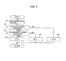
- FIG. 2 is a flow chart showing a flow of failure detecting operation.
- Step 1 it reads time-series data of the actual compression ratio.
- the time-series data of the actual compression ratio is obtained at predetermined sampling intervals, and is stored in the form of a predetermined number of latest sampling data in a RAM of engine controller 13.
- Step 2 based on the plurality of latest data of the actual compression ratio, it determines whether or not the amplitude of oscillation of the actual compression ratio (difference between maximum and minimum) shown by the time-series data is within a normal range.
- Step 3 When the amplitude of oscillation of the actual compression ratio is within the normal range, it proceeds to Step 3 where it further determines whether nor not the deviation between the actual compression ratio and the target compression ratio is within a normal range.
- Step 4 failure evaluation flag fF is set to "0".
- Step 5 failure evaluation flag fF is set to "1".
- the stuck state failure where the compression ratio is fixed is out of the target of the operation of the present embodiment, because the compression ratio is never increased by the fuel cut operation.
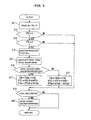
- FIG. 3 is a main flow chart showing a flow of whole control.
- Step 11 it reads an engine rotational speed Ne, a fuel cut execution flag "fFc" indicative of execution of the fuel cut, and failure evaluation flag fF at the moment.
- Step 12 determines whether or not fuel cut execution flag fFc is equal to 1, namely, whether or not the fuel cut is being executed.
- Step 13 determines whether or not failure evaluation flag fF is equal to 2, namely, whether or not it is in the uncontrollable state failure.
- the answer at Step 12 or 13 is NO, it omits Steps 4 to 18, and proceeds to Step 19 described later.
- Step 14 When the answers at Steps 12 and 13 are YES, namely, when variable compression ratio mechanism 2 is in the uncontrollable state failure and the fuel cut is being executed, it proceeds to Step 14 where it reads the time series data of the actual compression ratio. It further proceeds to Step 15 where a basic throttle valve opening TVO0, a basic intake VTC advance quantity VTCi0, and a basic exhaust VTC retard quantity VTCe0 are calculated based on engine rotational speed Ne at the moment.
- the basic throttle valve opening TVO0 corresponds to a minimum opening with which a minimum required quantity of air can be obtained with respect to engine rotational speed Ne in the fuel cut operation.
- Step 16 based on the time series data of the actual compression ratio read at Step 14, it determines whether or not the actual compression ratio is changing toward the higher compression ratio side.
- Step 16 When it is determined at Step 16 that the actual compression ratio is changing toward the higher compression ratio side, it proceeds to Step 17 where a target throttle valve opening TVO is set to a value that is obtained by adding a throttle valve opening increasing correction value hTVO to basic throttle valve opening TVO0.
- the opening of throttle valve 14 is controlled in conformance with the target throttle valve opening TVO. As the target throttle valve opening TVO increases, the opening of throttle valve 14 increases.
- a target intake VTC advance quantity VTCi is set to a value that is obtained by adding an intake VTC advancing correction value hVTCi to basic intake VTC advance quantity VTCiO.
- Intake-side variable valve mechanism 7 that advances and retards the opening and closing timings of intake valves 4 is controlled in conformance with target intake VTC advance quantity VTCi.
- the target intake VTC advance quantity VTCi is relative to the most retarded position.
- the intake valve closing timing based on basic intake VTC advance quantity VTCi0 is more retarded than the suction bottom dead center.
- the addition of intake VTC advancing correction value hVTCi causes the intake valve closing timing to advance and approach the suction bottom dead center.
- a target exhaust VTC retard quantity VTCe is set to a value that is obtained by adding an exhaust VTC retarding correction value hVTCe1 to basic exhaust VTC retard quantity VTCe0.
- Exhaust-side variable valve mechanism 8 that advances and retards the opening and closing timings of exhaust valves 5 is controlled in conformance with target exhaust VTC retard quantity VTCe.
- the target exhaust VTC retard quantity VTCe is relative to the most advanced position. As target exhaust VTC retard quantity VTCe increases, the opening and closing timings of exhaust valves 5 become retarded.
- the exhaust valve opening timing based on basic exhaust VTC retard quantity VTCe0 is more advanced than the expansion bottom dead center.
- the addition of exhaust VTC retarding correction value hVTCe1 causes the exhaust valve opening timing to retard and approach the expansion bottom dead center.
- FIG. 4 shows characteristics of the in-cylinder pressure when variable compression ratio mechanism 2 is normal (namely, based on basic throttle valve opening TVO0, basic intake VTC advance quantity VTCi0, and basic exhaust VTC retard quantity VTCe0), and characteristics when it is determined that variable compression ratio mechanism 2 is in the uncontrollable state failure, and the correcting operation of Step 17 is performed, in comparison.
- the in-cylinder pressure is first raised as a whole by the increase correction of target throttle valve opening TVO. This reduces the in-cylinder negative pressure during suction stroke, and weakens the force biasing the piston 24 upward to the top dead center side.
- the intake valve closing timing (IVC) approaches the suction bottom dead center
- the exhaust valve opening timing (EVO) approaches the expansion bottom dead center, so that the in-cylinder positive pressure during compression stroke and expansion stroke increases. This strengthens the force biasing the piston 24 toward the bottom dead center side.
- variable compression ratio mechanism 2 tends to shift toward the lower compression ratio side or higher compression ratio side by the balance between the alternating torques in two directions, which are applied as reaction forces to control shaft 28.
- the tendency toward the lower compression ratio side is enhanced, so that the compression ratio of variable compression ratio mechanism 2 gradually decreases. Even if the relationship with the piston inertial force prevents shifting toward the lower compression ratio side, the shifting toward the higher compression ratio side is at least suppressed.
- Step 16 when it is determined at Step 16 that the actual compression ratio is not changing toward the higher compression ratio side (in most situations, the actual compression ratio is being changed toward the lower compression ratio side by the operation of Step 17), it proceeds to Step 18.
- Step 18 it treats target throttle valve opening TVO and target intake VTC advance quantity VTCi similarly as at Step 17. Namely, target throttle valve opening TVO is set greater than under the normal condition, and target intake VTC advance quantity VTCi is set more advanced than under the normal condition.
- target exhaust VTC retard quantity VTCe is set to a value that is obtained by subtracting an exhaust VTC advancing correction value hVTCe2 from basic exhaust VTC retard quantity VTCe0.
- the exhaust valve opening timing based on basic exhaust VTC retard quantity VTCe0 is more advanced than the expansion bottom dead center.
- the subtraction of exhaust VTC retarding correction value hVTCe1 causes the exhaust valve opening timing to be more advanced than under the normal condition.
- the engine braking effect can be enhanced without increase of suction negative pressure. Namely, in the state where the compression ratio is prevented from becoming excessively high by the operation of Step 17, the excessively high compression ratio is prevented by the increase of target throttle valve opening TVO and the advance of target intake VTC advance quantity VTCi, and the engine braking torque is ensured by the advance of target exhaust VTC retard quantity VTCe.
- the next steps 19 and 20 are to prevent possible interference between piston 24 and intake valves 4 and exhaust valves 5 in proximity to the top dead center.
- Step 19 it determines whether or not the actual compression ratio at the moment is greater than or equal to an upper limit determined in account of prevention of the interference.
- the upper limit of compression ratio is calculated based on an actual intake VTC advance quantity rVTCi and an actual exhaust VTC retard quantity rVTCe, for example.
- Step 20 performs an interference prevention control with high priority. Specifically, it corrects target intake VTC advance quantity VTCi to the retard side, and corrects target exhaust VTC retard quantity VTCe to the advance side.
- the interference with piston 24 is prevented by the retard of the intake valve opening timing and the advance of the exhaust valve closing timing.
- This interference prevention control is performed with high priority to the operations of Steps 17 and 18, irrespective of whether variable compression ratio mechanism 2 is failed and whether the fuel cut is being executed.
- the interference prevention control may be implemented by the control of actively increasing the distance between piston 24 and intake valves 4 and exhaust valves 5 as described above, or by limiting the maximum values of target intake VTC advance quantity VTCi and target exhaust VTC retard quantity VTCe depending on the actual compression ratio.
- the present invention is described with reference to one specific embodiment, the invention is not limited to the embodiment but may be modified variously.
- all of the increase of the throttle valve opening, the advance of the intake valve closing timing, and the retard of the exhaust valve opening timing are performed simultaneously at Step 17 for prevention of excessively high compression ratio in the present embodiment, it may be modified so that only one or two of them are performed.
- the present invention is applicable to internal combustion engines provided with no variable valve mechanisms 7, 8.
- variable compression ratio mechanism 2 configured to vary the compression ration by varying the top dead center position of piston 24 vertically
- the present invention is applicable to variable compression ratio mechanisms as disclosed in patent documents 1 and 2 where the cylinder side is moved vertically.
- the actuator for varying the compression ratio in variable compression ratio mechanism 2 is not limited to electric motor 31 in the present embodiment, but the present invention is applicable to cases where the actuator is a hydraulic actuator.
Landscapes
- Engineering & Computer Science (AREA)
- Chemical & Material Sciences (AREA)
- Combustion & Propulsion (AREA)
- Mechanical Engineering (AREA)
- General Engineering & Computer Science (AREA)
- Output Control And Ontrol Of Special Type Engine (AREA)
- Electrical Control Of Air Or Fuel Supplied To Internal-Combustion Engine (AREA)
- Combined Controls Of Internal Combustion Engines (AREA)
Abstract
Description
- The present invention relates generally to an internal combustion engine which includes a variable compression ratio mechanism configured to vary a mechanical compression ratio by varying a positional relationship between a piston and a cylinder, and particularly to a control apparatus and a control method for performing an operation against a failure in a drive mechanism of the variable compression ratio mechanism.
- In the technical field of internal combustion engine, various types of variable compression ratio mechanisms have been known. For example, many variable compression ratio mechanisms have been proposed by the present applicant and others, in which a piston top dead center position is displaced vertically by varying a link geometry of a multi-link type piston crank mechanism.
Patent documents - In such a variable compression ratio mechanism, when a drive mechanism for varying the compression ratio is failed, it may become impossible to control the compression ratio, so that the compression ratio may become higher than intended.
- As a fail-safe function for such a failure in the drive mechanism,
patent document 1 discloses adding a hydraulic circuit for abnormal condition, in a configuration that a cylinder side and a crank case side are configured to be moved relative to each other by a hydraulic drive mechanism. The hydraulic circuit for abnormal condition is configured to guide working oil between two hydraulic chambers, to allow the compression ratio to vary only to a lower compression ratio side, when the hydraulic drive mechanism is abnormal. -
Patent document 2 discloses a variable compression ratio mechanism employing an electric motor as a drive mechanism, in which a helical torsion coil spring is provided to apply a force to bias the variable compression ratio mechanism toward the lower compression ratio side. In this mechanism, the biasing force becomes maximized, when the compression ratio is maximized. When the electric motor is failed, the variable compression ratio mechanism is promoted to return to a low compression ratio state by the biasing force of the helical torsion coil spring. - However, according to the configuration of
patent document 1, the additional hydraulic circuit for abnormal condition is required, so that the configuration becomes complex, and it is impossible to handle an abnormality in the drive mechanism itself, such as leakage of oil pressure. This configuration is not applicable to cases where the drive mechanism is implemented by another type of mechanism than the hydraulic mechanism (for example, a mechanism employing an electric motor). - On the other hand, according to the configuration of
patent document 2 which is biased toward the lower compression ratio side by the spring, when an actuator (electric motor, etc.) drives under a normal condition, the load of driving is large so that the actuator may have to be large-sized, which may adversely affect the fuel efficiency. -
- Patent Document 1:
JP 2010-185393 A - Patent Document 2:
JP 2009-062926 A - According to the present invention, an internal combustion engine control apparatus comprises: a variable compression ratio mechanism configured to vary a mechanical compression ratio by varying a positional relationship between a piston and a cylinder; a fuel cut means configured to perform a fuel cut in a predetermined decelerating state; a failure detecting means configured to detect a failure in the variable compression ratio mechanism; and a failed-state control means configured to perform at least one of first and second operations, while the fuel cut is being carried out by the fuel cut means under condition that the variable compression ratio mechanism is failed, wherein the first operation is to set lower an in-cylinder negative pressure during suction stroke than while the fuel cut is being performed under condition that the variable compression ratio mechanism is normal, and wherein the second operation is to set higher an in-cylinder positive pressure during compression stroke to expansion stroke than while the fuel cut is being performed under condition that the variable compression ratio mechanism is normal.
- Under the normal operating condition with combustion of fuel, the in-cylinder pressure during suction stroke is a negative pressure, but the in-cylinder pressure thereafter becomes high due to combustion pressure, so that the combustion pressure acts on the piston and a ceiling wall surface of a combustion chamber, and the variable compression ratio mechanism is biased basically in a direction to increase volumetric capacity of the combustion chamber, namely, in a direction to reduce the compression ratio. Accordingly, the compression ratio decreases gradually, even in a situation where the variable compression ratio mechanism fails to be actively controlled, due to some failure. However, when the fuel cut is being performed and no combustion is performed in decelerating state, the in-cylinder pressure during suction stroke is a negative pressure, and a condition is dominant where the negative pressure acts on the piston and the ceiling wall surface of the combustion chamber, so that the variable compression ratio mechanism may be shifted toward the higher compression ratio side.
- In this regard, according to the present invention, under a condition that a failure is detected in the variable compression ratio mechanism, the in-cylinder negative pressure during suction stroke is set lower when the fuel cut is being operated, than under a condition that the variable compression ratio mechanism is normal. This suppresses the negative pressure from shifting the variable compression ratio mechanism toward the higher compression ratio side. Moreover, the increase of the in-cylinder positive pressure during compression stroke to expansion stroke acts in the direction to expand the volumetric capacity of the combustion chamber, and thereby suppresses the variable compression ratio mechanism from shifting toward the higher compression ratio side.
- According to the present invention, it is possible to suppress the variable compression ratio mechanism from shifting toward the higher compression ratio side due to fuel cut operation, when the variable compression ratio mechanism is failed.
-
-
FIG. 1 is a configuration diagram showing system configuration of a control apparatus according to an embodiment of the present invention. -
FIG. 2 is a flow chart showing a failure detecting control according to this embodiment. -
FIG. 3 is a main flow chart showing a flow of whole control. -
FIG. 4 is a characteristic diagram showing changes in in-cylinder pressure at fuel-cut operation, when a variable compression ratio mechanism is normal, and when the variable compression ratio mechanism is failed, in comparison. - The following describes an embodiment of the present invention in detail with reference to the drawings.
-
FIG. 1 shows system configuration of an automotiveinternal combustion engine 1 to which the present invention is applied. For example,internal combustion engine 1 is a four-stroke cycle, spark-ignition type internal combustion engine which is provided with a variablecompression ratio mechanism 2 which employs a multi-link type piston crank mechanism. A pair ofintake valves 4 and a pair ofexhaust valves 5 are arranged at a ceiling wall surface of eachcylinder 3, and anignition plug 6 is arranged at a central portion surrounded byintake valves 4 andexhaust valves 5. -
Intake valves 4 are provided with an intake-side variable valve mechanism 7 configured to control opening and closing timings ofintake valves 4 variably.Exhaust valves 5 are provided with an exhaust-side variable valve mechanism 8 configured to control opening and closing timings ofexhaust valves 5 variably. Variable valve mechanisms 7, 8 may be configured to vary the opening timing and the closing timing independently from each other, or may be configured to advance and retard the opening timing and the closing timing simultaneously with each other. The present embodiment employs the latter type, which is configured to advance and retard the phase of a camshaft. - A
fuel injection valve 11 is provided per cylinder and arranged in anintake air passage 10 that is connected to acombustion chamber 9 viaintake valves 4. An electronically controlledthrottle valve 14 is disposed upstream of anintake air collector 12 inintake air passage 10, wherein the opening ofthrottle valve 14 is controlled based on a control signal from anengine controller 13. Anair flow meter 15 is disposed further upstream ofthrottle valve 14, whereinair flow meter 15 senses an intake air quantity. - A
catalytic device 17 is disposed in anexhaust gas passage 16 that is connected tocombustion chamber 9 viaexhaust valves 5, whereincatalytic device 17 is composed of a three-way catalyst. An airfuel ratio sensor 18 is disposed upstream ofcatalytic device 17 for sensing the air-fuel ratio. -
Engine controller 13 receives input of sensing signals from sensors, such asair flow meter 15, airfuel ratio sensor 18, acrank angle sensor 19 for sensing the engine rotational speed, awater temperature sensor 20 for sensing the temperature of cooling water, and anaccelerator opening sensor 21 for sensing the amount of depression of an accelerator pedal operated by a driver. Based on the sensing signals,engine controller 13 optimally controls the fuel injection quantity and injection timing offuel injection valve 11, the ignition timing ofignition plug 6, the opening and closing timings ofintake valves 4 andexhaust valves 5, the opening ofthrottle valve 14, and others. - On the other hand, variable
compression ratio mechanism 2 employs a known multi-link type piston crank mechanism as disclosed byJP 2004-116434 A compression ratio mechanism 2 generally includes: alower link 22 that is rotatably supported by acrank pin 21a of acrankshaft 21; anupper link 25 that links anupper pin 23 at a first end portion oflower link 22 and apiston pin 24a of apiston 24 to each other; acontrol link 27 that includes a first end connected to acontrol pin 26 at a second end portion oflower link 22; and acontrol shaft 28 that supports a second end ofcontrol link 27 for allowing swinging motion ofcontrol link 27.Crankshaft 21 andcontrol shaft 28 are rotatably supported via a bearing structure not shown in acrank case 29a at a lower part of acylinder block 29.Control shaft 28 includes aneccentric shaft part 28a whose location moves along with rotation ofcontrol shaft 28, and which is rotatably fitted with the end portion ofcontrol link 27. In variablecompression ratio mechanism 2, the top dead center position ofpiston 24 travels upward and downward along with rotation ofcontrol shaft 28, thereby varying the mechanical compression ratio. - In this embodiment, as a drive mechanism for controlling the compression ratio of variable
compression ratio mechanism 2 variably, anelectric motor 31 is disposed at an outer wall surface ofcrank case 29a, whereinelectric motor 31 has a central rotation axis parallel tocrankshaft 21, and aspeed reducer 32 is aligned withelectric motor 31 in the axial direction.Speed reducer 32 is implemented by a harmonic drive mechanism having a large gear ratio, for example, and includes a speedreducer output shaft 32a that is disposed coaxially with an output shaft not shown ofelectric motor 31. Accordingly, speedreducer output shaft 32a andcontrol shaft 28 are parallel to each other, and rotated simultaneously by a configuration that a first arm 33 fixed to speedreducer output shaft 32a and asecond arm 34 fixed tocontrol shaft 28 are linked with each other by anintermediate link 35. - When
electric motor 31 rotates, the angle of speedreducer output shaft 32a varies with a significant speed reduction byspeed reducer 32. The rotation of speedreducer output shaft 32a is transmitted from first arm 33 tosecond arm 34 viaintermediate link 35, to rotatecontrol shaft 28. This changes the mechanical compression ratio ofinternal combustion engine 1 as described above. In the shown example, first arm 33 andsecond arm 34 extend in opposite directions, so that when speedreducer output shaft 32a rotates in the clockwise direction,control shaft 28 rotates in the counterclockwise direction. However, this configuration may be modified so that speedreducer output shaft 32a andcontrol shaft 28 rotate in the same direction. - An actual compression ratio, namely, an actual value of the mechanical compression ratio controlled variably by variable
compression ratio mechanism 2 as described above, is sensed by an actualcompression ratio sensor 36. For example, actualcompression ratio sensor 36 is composed of a rotary-type potentiometer or rotary encoder for sensing the rotation angle ofcontrol shaft 28 or speedreducer output shaft 32a. Alternatively, the sensing of the actual compression ratio may be implemented without additional sensors by determining the amount of rotation ofelectric motor 31 based on the command signal toelectric motor 31, and determining the rotation angle ofcontrol shaft 28 based of the amount of rotation ofelectric motor 31. -
Electric motor 31 is controlled byengine controller 13 to be driven to conform the actual compression ratio obtained as described above to a target compression ratio corresponding to the operating condition. - In variable
compression ratio mechanism 2 configured as described above, the force resulting from in-cylinder pressure, and the inertial force act onpiston 24 that is supported viaupper link 25. The in-cylinder pressure becomes a negative pressure during suction stroke, and becomes a positive pressure even in motoring during compression stroke and expansion stroke. In the normal operating state with combustion, the combustion pressure acts during expansion stroke. The inertial force acts in two vertical directions.Piston 24 is applied with these forces, so thatcontrol shaft 28 havingeccentric shaft part 28a is applied with an alternating torque that forcescontrol shaft 28 to rotate alternately in the direction to reduce the compression ratio and in the direction to increase the compression ratio. - When the drive mechanism including
electric motor 31 is normal, the rotational angle position ofcontrol shaft 28 is maintained at a desired position (corresponding to a target compression ratio) against the alternating torque. In contrast, when the driving torque to controlshaft 28 is lost by a failure in the drive mechanism such as a disconnection inelectric motor 31,control shaft 28 oscillates in the rotational direction by the alternating torque, and gradually shifts toward the lower compression ratio side or the higher compression ratio side in conformance with the balance between the toques in the two directions. - In the normal operating state where combustion is performed in the cylinder, a high combustion pressure acts on
piston 24 during expansion stroke, so that the torque to rotatecontrol shaft 28 toward the lower compression ratio side is relatively large, and thereby controlshaft 28 gradually shifts toward the lower compression ratio side. - However, during the fuel cut operation during deceleration in which no combustion is performed, no combustion pressure is applied, and the effect of the in-cylinder negative pressure during suction stroke becomes high, so that the torque to rotate
control shaft 28 in the direction to increase the compression ratio becomes relatively large. In this situation, controlshaft 28 gradually shifts toward the higher compression ratio side. - It is not preferable in view of occurrence of abnormal combustion that the compression ratio becomes excessively higher than the original target compression ratio. If the compression ratio becomes excessively high in relation to the opening and closing characteristics of
intake valves 4 andexhaust valves 5, it causes a problem of interference betweenpiston 24 andintake valves 4 andexhaust valves 5. In order to avoid the problem, it becomes necessary to provide a large valve recess that is too large in the normal operation. - In the present embodiment, a diagnosis is performed for a failure of variable
compression ratio mechanism 2 including the drive mechanism employing theelectric motor 31. When the fuel cut is performed during deceleration under the condition that a failure is detected, the in-cylinder negative pressure during suction stroke is set lower than under the normal condition, or the in-cylinder positive pressure during compression stroke to expansion stroke is set higher than under the normal condition. - The following describes a specific process with reference to flow charts of
FIGS. 2 and3 . -
FIG. 2 is a flow chart showing a flow of failure detecting operation. AtStep 1, it reads time-series data of the actual compression ratio. The time-series data of the actual compression ratio is obtained at predetermined sampling intervals, and is stored in the form of a predetermined number of latest sampling data in a RAM ofengine controller 13. AtStep 2, based on the plurality of latest data of the actual compression ratio, it determines whether or not the amplitude of oscillation of the actual compression ratio (difference between maximum and minimum) shown by the time-series data is within a normal range. - When the amplitude of oscillation of the actual compression ratio is excessively large, it proceeds to Step 6 where a failure evaluation flag "fF" is set to "2". fF=2 indicates an uncontrollable state failure that no normal compression ratio control is performed by the drive mechanism, but variable
compression ratio mechanism 2 is substantially in free state. - When the amplitude of oscillation of the actual compression ratio is within the normal range, it proceeds to Step 3 where it further determines whether nor not the deviation between the actual compression ratio and the target compression ratio is within a normal range.
- When the deviation therebetween is within the normal range, it proceeds to Step 4 where failure evaluation flag fF is set to "0". fF=0 indicates that variable
compression ratio mechanism 2 is not failed. When the deviation therebetween is excessively large, it proceeds to Step 5 where failure evaluation flag fF is set to "1". fF=1 indicates a stuck state failure that some portion of the drive mechanism fromelectric motor 31 to controlshaft 28 is stuck so that the compression ratio cannot be changed. The stuck state failure where the compression ratio is fixed is out of the target of the operation of the present embodiment, because the compression ratio is never increased by the fuel cut operation. -
FIG. 3 is a main flow chart showing a flow of whole control. AtStep 11, it reads an engine rotational speed Ne, a fuel cut execution flag "fFc" indicative of execution of the fuel cut, and failure evaluation flag fF at the moment. fFC=1 indicates that the fuel cut is being executed, and fFc=0 indicates that the fuel cut is not being executed. - At
Step 12, it determines whether or not fuel cut execution flag fFc is equal to 1, namely, whether or not the fuel cut is being executed. AtStep 13, it determines whether or not failure evaluation flag fF is equal to 2, namely, whether or not it is in the uncontrollable state failure. When the answer atStep Steps 4 to 18, and proceeds to Step 19 described later. - When the answers at
Steps compression ratio mechanism 2 is in the uncontrollable state failure and the fuel cut is being executed, it proceeds to Step 14 where it reads the time series data of the actual compression ratio. It further proceeds to Step 15 where a basic throttle valve opening TVO0, a basic intake VTC advance quantity VTCi0, and a basic exhaust VTC retard quantity VTCe0 are calculated based on engine rotational speed Ne at the moment. The basic throttle valve opening TVO0 corresponds to a minimum opening with which a minimum required quantity of air can be obtained with respect to engine rotational speed Ne in the fuel cut operation. - Next, at
Step 16, based on the time series data of the actual compression ratio read atStep 14, it determines whether or not the actual compression ratio is changing toward the higher compression ratio side. - When it is determined at
Step 16 that the actual compression ratio is changing toward the higher compression ratio side, it proceeds to Step 17 where a target throttle valve opening TVO is set to a value that is obtained by adding a throttle valve opening increasing correction value hTVO to basic throttle valve opening TVO0. The opening ofthrottle valve 14 is controlled in conformance with the target throttle valve opening TVO. As the target throttle valve opening TVO increases, the opening ofthrottle valve 14 increases. - Moreover, a target intake VTC advance quantity VTCi is set to a value that is obtained by adding an intake VTC advancing correction value hVTCi to basic intake VTC advance quantity VTCiO. Intake-side variable valve mechanism 7 that advances and retards the opening and closing timings of
intake valves 4 is controlled in conformance with target intake VTC advance quantity VTCi. The target intake VTC advance quantity VTCi is relative to the most retarded position. As target intake VTC advance quantity VTCi increases, the opening and closing timings ofintake valves 4 become advanced. The intake valve closing timing based on basic intake VTC advance quantity VTCi0 is more retarded than the suction bottom dead center. The addition of intake VTC advancing correction value hVTCi causes the intake valve closing timing to advance and approach the suction bottom dead center. - Moreover, at
Step 17, a target exhaust VTC retard quantity VTCe is set to a value that is obtained by adding an exhaust VTC retarding correction value hVTCe1 to basic exhaust VTC retard quantity VTCe0. Exhaust-side variable valve mechanism 8 that advances and retards the opening and closing timings ofexhaust valves 5 is controlled in conformance with target exhaust VTC retard quantity VTCe. The target exhaust VTC retard quantity VTCe is relative to the most advanced position. As target exhaust VTC retard quantity VTCe increases, the opening and closing timings ofexhaust valves 5 become retarded. The exhaust valve opening timing based on basic exhaust VTC retard quantity VTCe0 is more advanced than the expansion bottom dead center. The addition of exhaust VTC retarding correction value hVTCe1 causes the exhaust valve opening timing to retard and approach the expansion bottom dead center. - By the operation of
Step 17, the in-cylinder pressure during the fuel cut operation is set as shown inFIG. 4 . Specifically,FIG. 4 shows characteristics of the in-cylinder pressure when variablecompression ratio mechanism 2 is normal (namely, based on basic throttle valve opening TVO0, basic intake VTC advance quantity VTCi0, and basic exhaust VTC retard quantity VTCe0), and characteristics when it is determined that variablecompression ratio mechanism 2 is in the uncontrollable state failure, and the correcting operation ofStep 17 is performed, in comparison. Under the failed condition, the in-cylinder pressure is first raised as a whole by the increase correction of target throttle valve opening TVO. This reduces the in-cylinder negative pressure during suction stroke, and weakens the force biasing thepiston 24 upward to the top dead center side. Moreover, the intake valve closing timing (IVC) approaches the suction bottom dead center, and the exhaust valve opening timing (EVO) approaches the expansion bottom dead center, so that the in-cylinder positive pressure during compression stroke and expansion stroke increases. This strengthens the force biasing thepiston 24 toward the bottom dead center side. - As described above, in the uncontrollable state failure, variable
compression ratio mechanism 2 tends to shift toward the lower compression ratio side or higher compression ratio side by the balance between the alternating torques in two directions, which are applied as reaction forces to controlshaft 28. By varying the in-cylinder pressure as compared to the normal condition as described above, the tendency toward the lower compression ratio side is enhanced, so that the compression ratio of variablecompression ratio mechanism 2 gradually decreases. Even if the relationship with the piston inertial force prevents shifting toward the lower compression ratio side, the shifting toward the higher compression ratio side is at least suppressed. - On the other hand, when it is determined at
Step 16 that the actual compression ratio is not changing toward the higher compression ratio side (in most situations, the actual compression ratio is being changed toward the lower compression ratio side by the operation of Step 17), it proceeds to Step 18. AtStep 18, it treats target throttle valve opening TVO and target intake VTC advance quantity VTCi similarly as atStep 17. Namely, target throttle valve opening TVO is set greater than under the normal condition, and target intake VTC advance quantity VTCi is set more advanced than under the normal condition. - On the other hand, target exhaust VTC retard quantity VTCe is set to a value that is obtained by subtracting an exhaust VTC advancing correction value hVTCe2 from basic exhaust VTC retard quantity VTCe0. As described above, the exhaust valve opening timing based on basic exhaust VTC retard quantity VTCe0 is more advanced than the expansion bottom dead center. The subtraction of exhaust VTC retarding correction value hVTCe1 causes the exhaust valve opening timing to be more advanced than under the normal condition.
- By advancing the exhaust valve opening timing during expansion stroke in this way, the engine braking effect can be enhanced without increase of suction negative pressure. Namely, in the state where the compression ratio is prevented from becoming excessively high by the operation of
Step 17, the excessively high compression ratio is prevented by the increase of target throttle valve opening TVO and the advance of target intake VTC advance quantity VTCi, and the engine braking torque is ensured by the advance of target exhaust VTC retard quantity VTCe. - The
next steps piston 24 andintake valves 4 andexhaust valves 5 in proximity to the top dead center. AtStep 19, it determines whether or not the actual compression ratio at the moment is greater than or equal to an upper limit determined in account of prevention of the interference. The upper limit of compression ratio is calculated based on an actual intake VTC advance quantity rVTCi and an actual exhaust VTC retard quantity rVTCe, for example. Then, when the actual compression has reached the upper limit, atStep 20, it performs an interference prevention control with high priority. Specifically, it corrects target intake VTC advance quantity VTCi to the retard side, and corrects target exhaust VTC retard quantity VTCe to the advance side. Namely, the interference withpiston 24 is prevented by the retard of the intake valve opening timing and the advance of the exhaust valve closing timing. This interference prevention control is performed with high priority to the operations ofSteps compression ratio mechanism 2 is failed and whether the fuel cut is being executed. The interference prevention control may be implemented by the control of actively increasing the distance betweenpiston 24 andintake valves 4 andexhaust valves 5 as described above, or by limiting the maximum values of target intake VTC advance quantity VTCi and target exhaust VTC retard quantity VTCe depending on the actual compression ratio. - Although the present invention is described with reference to one specific embodiment, the invention is not limited to the embodiment but may be modified variously. For example, although all of the increase of the throttle valve opening, the advance of the intake valve closing timing, and the retard of the exhaust valve opening timing are performed simultaneously at
Step 17 for prevention of excessively high compression ratio in the present embodiment, it may be modified so that only one or two of them are performed. For example, the present invention is applicable to internal combustion engines provided with no variable valve mechanisms 7, 8. - Although variable
compression ratio mechanism 2 configured to vary the compression ration by varying the top dead center position ofpiston 24 vertically is employed in this embodiment, the present invention is applicable to variable compression ratio mechanisms as disclosed inpatent documents compression ratio mechanism 2 is not limited toelectric motor 31 in the present embodiment, but the present invention is applicable to cases where the actuator is a hydraulic actuator.
Claims (8)
- An internal combustion engine control apparatus comprising:a variable compression ratio mechanism configured to vary a mechanical compression ratio by varying a positional relationship between a piston and a cylinder;a fuel cut means configured to perform a fuel cut in a predetermined decelerating state;a failure detecting means configured to detect a failure in the variable compression ratio mechanism; anda failed-state control means configured to perform at least one of first and second operations, while the fuel cut is being carried out by the fuel cut means under condition that the variable compression ratio mechanism is failed, wherein the first operation is to set lower an in-cylinder negative pressure during suction stroke than while the fuel cut is being performed under condition that the variable compression ratio mechanism is normal, and wherein the second operation is to set higher an in-cylinder positive pressure during compression stroke to expansion stroke than while the fuel cut is being performed under condition that the variable compression ratio mechanism is normal.
- The internal combustion engine control apparatus as claimed in Claim 1, further comprising a throttle valve configured to control an intake air quantity, wherein the failed-state control means is configured to set larger an opening of the throttle valve than under condition that the variable compression ratio mechanism is normal.
- The internal combustion engine control apparatus as claimed in Claim 1 or 2, further comprising an intake-side variable valve mechanism configured to vary an intake valve closing timing, wherein the failed-state control means is configured to set the intake valve closing timing more advanced toward intake bottom dead center than under condition that the variable compression ratio mechanism is normal.
- The internal combustion engine control apparatus as claimed in any one of Claims 1 to 3, further comprising an exhaust-side variable valve mechanism configured to vary an exhaust valve opening timing, wherein the failed-state control means is configured to set the exhaust valve opening timing more retarded toward expansion bottom dead center than under condition that the variable compression ratio mechanism is normal.
- The internal combustion engine control apparatus as claimed in any one of Claims 1 to 3, further comprising an exhaust-side variable valve mechanism configured to vary an exhaust valve opening timing, wherein the failed-state control means is configured to set lower the in-cylinder negative pressure during suction stroke, and set the exhaust valve opening timing more advanced away from expansion bottom dead center, than under condition that the variable compression ratio mechanism is normal.
- The internal combustion engine control apparatus as claimed in any one of Claims 1 to 5, further comprising:an intake-side variable valve mechanism configured to vary an intake valve opening timing; andan actual compression ratio sensing means configured to sense an actual compression ratio of the variable compression ratio mechanism;wherein the failed-state control means is configured to set the intake valve opening timing more retarded with high priority, when the actual compression ratio is greater than or equal to a predetermined value.
- The internal combustion engine control apparatus as claimed in any one of Claims 1 to 5, further comprising:an exhaust-side variable valve mechanism configured to vary an exhaust valve closing timing; andan actual compression ratio sensing means configured to sense an actual compression ratio of the variable compression ratio mechanism;wherein the failed-state control means is configured to set the exhaust valve closing timing more advanced with high priority, when the actual compression ratio is greater than or equal to a predetermined value.
- An internal combustion engine control method for an internal combustion engine, wherein the internal combustion engine includes a variable compression ratio mechanism configured to vary a mechanical compression ratio by varying a positional relationship between a piston and a cylinder, and is configured to perform a fuel cut in a predetermined decelerating state, the internal combustion engine control method comprising:detecting a failure in the variable compression ratio mechanism; andperforming at least one of first and second operations, while the fuel cut is being carried out by the fuel cut means under condition that the variable compression ratio mechanism is failed, wherein the first operation is to set lower an in-cylinder negative pressure during suction stroke than while the fuel cut is being performed under condition that the variable compression ratio mechanism is normal, and wherein the second operation is to set higher an in-cylinder positive pressure during compression stroke to expansion stroke than while the fuel cut is being performed under condition that the variable compression ratio mechanism is normal.
Applications Claiming Priority (2)
| Application Number | Priority Date | Filing Date | Title |
|---|---|---|---|
| JP2013006396 | 2013-01-17 | ||
| PCT/JP2013/081227 WO2014112201A1 (en) | 2013-01-17 | 2013-11-20 | Internal-combustion-engine control device and control method |
Publications (3)
| Publication Number | Publication Date |
|---|---|
| EP2947298A1 true EP2947298A1 (en) | 2015-11-25 |
| EP2947298A4 EP2947298A4 (en) | 2016-01-20 |
| EP2947298B1 EP2947298B1 (en) | 2017-10-04 |
Family
ID=51209313
Family Applications (1)
| Application Number | Title | Priority Date | Filing Date |
|---|---|---|---|
| EP13871586.7A Active EP2947298B1 (en) | 2013-01-17 | 2013-11-20 | Internal-combustion-engine control device and control method |
Country Status (8)
| Country | Link |
|---|---|
| US (1) | US9416745B2 (en) |
| EP (1) | EP2947298B1 (en) |
| JP (1) | JP5765494B2 (en) |
| CN (1) | CN104937243B (en) |
| BR (1) | BR112015016969B1 (en) |
| MX (1) | MX340771B (en) |
| RU (1) | RU2598487C1 (en) |
| WO (1) | WO2014112201A1 (en) |
Families Citing this family (14)
| Publication number | Priority date | Publication date | Assignee | Title |
|---|---|---|---|---|
| JP6259332B2 (en) * | 2014-03-20 | 2018-01-10 | 日立オートモティブシステムズ株式会社 | Control device for internal combustion engine |
| JP6477278B2 (en) * | 2015-06-16 | 2019-03-06 | 日産自動車株式会社 | Control device for variable compression ratio internal combustion engine |
| JP6509666B2 (en) * | 2015-07-29 | 2019-05-08 | 日立オートモティブシステムズ株式会社 | Variable compression ratio device for internal combustion engine |
| DE102017115876B4 (en) * | 2016-08-16 | 2022-12-15 | Toyota Jidosha Kabushiki Kaisha | Anomaly diagnosis device for a mechanism for varying a compression ratio |
| DE102016011392A1 (en) * | 2016-09-21 | 2018-03-22 | GM Global Technology Operations, LLC (n.d. Ges. d. Staates Delaware) | Internal combustion engine |
| JP6791746B2 (en) * | 2016-12-22 | 2020-11-25 | トヨタ自動車株式会社 | Internal combustion engine control device and control method |
| KR102359916B1 (en) * | 2017-04-21 | 2022-02-07 | 현대자동차 주식회사 | Apparatus and method for diagnozing engine having variable compression ratio apparatus |
| JP7101460B2 (en) * | 2017-05-10 | 2022-07-15 | 日立Astemo株式会社 | Internal combustion engine control device |
| WO2019003326A1 (en) * | 2017-06-28 | 2019-01-03 | 日産自動車株式会社 | Control method and control device for internal combustion engine |
| CN110998072B (en) * | 2017-08-03 | 2021-11-09 | 雅各布斯车辆系统公司 | System and method for reverse flow management and valve motion sequencing in an enhanced internal combustion engine |
| US10450983B2 (en) * | 2017-12-11 | 2019-10-22 | Ford Global Technologies, Llc | Method and system for diagnosing operation of an engine compression ratio changing mechanism |
| US10612506B2 (en) * | 2018-01-08 | 2020-04-07 | Ford Global Technologies, Llc | Method and system for an engine |
| RU2762475C1 (en) * | 2021-05-31 | 2021-12-21 | Александр Михайлович Рудник | Internal combustion engine with variable compression ratio |
| CN116263132B (en) * | 2021-12-13 | 2025-12-19 | 广州汽车集团股份有限公司 | Engine compression ratio control method, device and storage medium |
Family Cites Families (18)
| Publication number | Priority date | Publication date | Assignee | Title |
|---|---|---|---|---|
| JPH0772515B2 (en) * | 1987-07-30 | 1995-08-02 | トヨタ自動車株式会社 | Control device for variable compression ratio internal combustion engine |
| JPH0821295A (en) * | 1994-05-06 | 1996-01-23 | Honda Motor Co Ltd | Control device for internal combustion engine |
| US6260532B1 (en) * | 1998-09-28 | 2001-07-17 | Edward Charles Mendler | Rigid crankshaft cradle and actuator |
| US6443107B1 (en) * | 1999-05-27 | 2002-09-03 | Edward Charles Mendler | Rigid crankshaft cradle and actuator |
| DE19955250B4 (en) * | 1999-11-17 | 2005-05-04 | Robert Bosch Gmbh | Method and device for monitoring the function of a variable cylinder compression |
| US6665605B2 (en) * | 2002-03-25 | 2003-12-16 | Ford Global Technologies, Llc | System and method for controlling an engine |
| US6662768B2 (en) * | 2002-03-25 | 2003-12-16 | Ford Global Technologies, Llc | System and method for controlling an engine |
| US6732041B2 (en) * | 2002-04-25 | 2004-05-04 | Ford Global Technologies, Llc | Method and system for inferring intake manifold pressure of a variable compression ratio engine |
| JP4134658B2 (en) | 2002-09-27 | 2008-08-20 | 日産自動車株式会社 | Reciprocating variable compression ratio engine |
| JP2004308510A (en) * | 2003-04-04 | 2004-11-04 | Toyota Motor Corp | Internal combustion engine that controls by detecting failure of the compression ratio changing mechanism |
| JP4200860B2 (en) * | 2003-08-28 | 2008-12-24 | 日産自動車株式会社 | Internal combustion engine with variable compression ratio mechanism |
| JP4309326B2 (en) * | 2004-10-06 | 2009-08-05 | 本田技研工業株式会社 | Plant control device |
| JP2009062926A (en) | 2007-09-07 | 2009-03-26 | Toyota Motor Corp | Variable compression ratio internal combustion engine |
| JP4367551B2 (en) * | 2007-11-06 | 2009-11-18 | トヨタ自動車株式会社 | Spark ignition internal combustion engine |
| JP2009293497A (en) * | 2008-06-04 | 2009-12-17 | Toyota Motor Corp | Variable compression ratio internal combustion engine, and abnormality determining method for variable compression ratio mechanism |
| JP5136454B2 (en) | 2009-02-13 | 2013-02-06 | トヨタ自動車株式会社 | Variable compression ratio internal combustion engine |
| WO2011148514A1 (en) * | 2010-05-24 | 2011-12-01 | トヨタ自動車株式会社 | Spark-ignition internal combustion engine |
| JP2012225165A (en) * | 2011-04-15 | 2012-11-15 | Nissan Motor Co Ltd | Variable compression ratio engine control apparatus |
-
2013
- 2013-11-20 BR BR112015016969-4A patent/BR112015016969B1/en active IP Right Grant
- 2013-11-20 MX MX2015009004A patent/MX340771B/en active IP Right Grant
- 2013-11-20 JP JP2014557342A patent/JP5765494B2/en active Active
- 2013-11-20 CN CN201380070833.9A patent/CN104937243B/en active Active
- 2013-11-20 EP EP13871586.7A patent/EP2947298B1/en active Active
- 2013-11-20 RU RU2015134349/06A patent/RU2598487C1/en active
- 2013-11-20 WO PCT/JP2013/081227 patent/WO2014112201A1/en not_active Ceased
- 2013-11-20 US US14/760,270 patent/US9416745B2/en active Active
Also Published As
| Publication number | Publication date |
|---|---|
| WO2014112201A1 (en) | 2014-07-24 |
| RU2598487C1 (en) | 2016-09-27 |
| US9416745B2 (en) | 2016-08-16 |
| US20150354488A1 (en) | 2015-12-10 |
| MX340771B (en) | 2016-07-26 |
| MX2015009004A (en) | 2015-09-16 |
| EP2947298A4 (en) | 2016-01-20 |
| CN104937243A (en) | 2015-09-23 |
| JP5765494B2 (en) | 2015-08-19 |
| EP2947298B1 (en) | 2017-10-04 |
| CN104937243B (en) | 2018-04-13 |
| BR112015016969A2 (en) | 2017-07-11 |
| BR112015016969B1 (en) | 2022-11-16 |
| JPWO2014112201A1 (en) | 2017-01-19 |
Similar Documents
| Publication | Publication Date | Title |
|---|---|---|
| US9416745B2 (en) | Internal-combustion-engine control device and control method | |
| US7661407B2 (en) | Control system for internal combustion engine | |
| US9046012B2 (en) | Variable valve operating apparatus for internal combustion engine | |
| JP4492523B2 (en) | Internal combustion engine with variable compression ratio and valve characteristics | |
| JP5652573B2 (en) | Control device and control method for internal combustion engine | |
| JP2014040775A (en) | Control device of engine | |
| EP2578847B1 (en) | Spark-ignition internal combustion engine | |
| US9765706B2 (en) | Controller for internal combustion engine | |
| JP5316086B2 (en) | Control device and control method for internal combustion engine | |
| JP6065451B2 (en) | Control device for internal combustion engine | |
| JP6733824B2 (en) | Control method and control device for internal combustion engine | |
| US7178493B2 (en) | Method and system to avoid piston-valve collision | |
| JP5092956B2 (en) | Method for controlling internal combustion engine for vehicle and internal combustion engine system | |
| JP5169682B2 (en) | Method for controlling internal combustion engine and internal combustion engine system | |
| JP4379273B2 (en) | Internal combustion engine with variable compression ratio mechanism | |
| JP5012565B2 (en) | Internal combustion engine control method and internal combustion engine system | |
| JP5136332B2 (en) | Method for controlling internal combustion engine and internal combustion engine system | |
| JP2008025383A (en) | Control device for internal combustion engine | |
| JP2014211122A (en) | Internal combustion engine | |
| JP2010159692A (en) | Control device of internal combustion engine |
Legal Events
| Date | Code | Title | Description |
|---|---|---|---|
| PUAI | Public reference made under article 153(3) epc to a published international application that has entered the european phase |
Free format text: ORIGINAL CODE: 0009012 |
|
| 17P | Request for examination filed |
Effective date: 20150810 |
|
| AK | Designated contracting states |
Kind code of ref document: A1 Designated state(s): AL AT BE BG CH CY CZ DE DK EE ES FI FR GB GR HR HU IE IS IT LI LT LU LV MC MK MT NL NO PL PT RO RS SE SI SK SM TR |
|
| AX | Request for extension of the european patent |
Extension state: BA ME |
|
| A4 | Supplementary search report drawn up and despatched |
Effective date: 20151217 |
|
| RIC1 | Information provided on ipc code assigned before grant |
Ipc: F02D 41/12 20060101ALI20151211BHEP Ipc: F02D 13/02 20060101ALI20151211BHEP Ipc: F02D 41/00 20060101ALI20151211BHEP Ipc: F02D 41/22 20060101ALI20151211BHEP Ipc: F02D 45/00 20060101ALI20151211BHEP Ipc: F02B 75/04 20060101ALI20151211BHEP Ipc: F02D 43/00 20060101ALI20151211BHEP Ipc: F02D 15/02 20060101AFI20151211BHEP |
|
| DAX | Request for extension of the european patent (deleted) | ||
| 17Q | First examination report despatched |
Effective date: 20161111 |
|
| GRAP | Despatch of communication of intention to grant a patent |
Free format text: ORIGINAL CODE: EPIDOSNIGR1 |
|
| INTG | Intention to grant announced |
Effective date: 20170616 |
|
| GRAA | (expected) grant |
Free format text: ORIGINAL CODE: 0009210 |
|
| GRAS | Grant fee paid |
Free format text: ORIGINAL CODE: EPIDOSNIGR3 |
|
| AK | Designated contracting states |
Kind code of ref document: B1 Designated state(s): AL AT BE BG CH CY CZ DE DK EE ES FI FR GB GR HR HU IE IS IT LI LT LU LV MC MK MT NL NO PL PT RO RS SE SI SK SM TR |
|
| REG | Reference to a national code |
Ref country code: GB Ref legal event code: FG4D |
|
| REG | Reference to a national code |
Ref country code: FR Ref legal event code: PLFP Year of fee payment: 5 |
|
| REG | Reference to a national code |
Ref country code: CH Ref legal event code: EP |
|
| REG | Reference to a national code |
Ref country code: AT Ref legal event code: REF Ref document number: 934287 Country of ref document: AT Kind code of ref document: T Effective date: 20171015 |
|
| REG | Reference to a national code |
Ref country code: IE Ref legal event code: FG4D |
|
| REG | Reference to a national code |
Ref country code: DE Ref legal event code: R096 Ref document number: 602013027677 Country of ref document: DE |
|
| REG | Reference to a national code |
Ref country code: NL Ref legal event code: MP Effective date: 20171004 |
|
| REG | Reference to a national code |
Ref country code: LT Ref legal event code: MG4D |
|
| REG | Reference to a national code |
Ref country code: AT Ref legal event code: MK05 Ref document number: 934287 Country of ref document: AT Kind code of ref document: T Effective date: 20171004 |
|
| PG25 | Lapsed in a contracting state [announced via postgrant information from national office to epo] |
Ref country code: NL Free format text: LAPSE BECAUSE OF FAILURE TO SUBMIT A TRANSLATION OF THE DESCRIPTION OR TO PAY THE FEE WITHIN THE PRESCRIBED TIME-LIMIT Effective date: 20171004 |
|
| PG25 | Lapsed in a contracting state [announced via postgrant information from national office to epo] |
Ref country code: LT Free format text: LAPSE BECAUSE OF FAILURE TO SUBMIT A TRANSLATION OF THE DESCRIPTION OR TO PAY THE FEE WITHIN THE PRESCRIBED TIME-LIMIT Effective date: 20171004 Ref country code: ES Free format text: LAPSE BECAUSE OF FAILURE TO SUBMIT A TRANSLATION OF THE DESCRIPTION OR TO PAY THE FEE WITHIN THE PRESCRIBED TIME-LIMIT Effective date: 20171004 Ref country code: NO Free format text: LAPSE BECAUSE OF FAILURE TO SUBMIT A TRANSLATION OF THE DESCRIPTION OR TO PAY THE FEE WITHIN THE PRESCRIBED TIME-LIMIT Effective date: 20180104 Ref country code: SE Free format text: LAPSE BECAUSE OF FAILURE TO SUBMIT A TRANSLATION OF THE DESCRIPTION OR TO PAY THE FEE WITHIN THE PRESCRIBED TIME-LIMIT Effective date: 20171004 Ref country code: FI Free format text: LAPSE BECAUSE OF FAILURE TO SUBMIT A TRANSLATION OF THE DESCRIPTION OR TO PAY THE FEE WITHIN THE PRESCRIBED TIME-LIMIT Effective date: 20171004 |
|
| PG25 | Lapsed in a contracting state [announced via postgrant information from national office to epo] |
Ref country code: GR Free format text: LAPSE BECAUSE OF FAILURE TO SUBMIT A TRANSLATION OF THE DESCRIPTION OR TO PAY THE FEE WITHIN THE PRESCRIBED TIME-LIMIT Effective date: 20180105 Ref country code: IS Free format text: LAPSE BECAUSE OF FAILURE TO SUBMIT A TRANSLATION OF THE DESCRIPTION OR TO PAY THE FEE WITHIN THE PRESCRIBED TIME-LIMIT Effective date: 20180204 Ref country code: AT Free format text: LAPSE BECAUSE OF FAILURE TO SUBMIT A TRANSLATION OF THE DESCRIPTION OR TO PAY THE FEE WITHIN THE PRESCRIBED TIME-LIMIT Effective date: 20171004 Ref country code: HR Free format text: LAPSE BECAUSE OF FAILURE TO SUBMIT A TRANSLATION OF THE DESCRIPTION OR TO PAY THE FEE WITHIN THE PRESCRIBED TIME-LIMIT Effective date: 20171004 Ref country code: LV Free format text: LAPSE BECAUSE OF FAILURE TO SUBMIT A TRANSLATION OF THE DESCRIPTION OR TO PAY THE FEE WITHIN THE PRESCRIBED TIME-LIMIT Effective date: 20171004 Ref country code: RS Free format text: LAPSE BECAUSE OF FAILURE TO SUBMIT A TRANSLATION OF THE DESCRIPTION OR TO PAY THE FEE WITHIN THE PRESCRIBED TIME-LIMIT Effective date: 20171004 Ref country code: BG Free format text: LAPSE BECAUSE OF FAILURE TO SUBMIT A TRANSLATION OF THE DESCRIPTION OR TO PAY THE FEE WITHIN THE PRESCRIBED TIME-LIMIT Effective date: 20180104 |
|
| REG | Reference to a national code |
Ref country code: DE Ref legal event code: R097 Ref document number: 602013027677 Country of ref document: DE |
|
| PG25 | Lapsed in a contracting state [announced via postgrant information from national office to epo] |
Ref country code: SK Free format text: LAPSE BECAUSE OF FAILURE TO SUBMIT A TRANSLATION OF THE DESCRIPTION OR TO PAY THE FEE WITHIN THE PRESCRIBED TIME-LIMIT Effective date: 20171004 Ref country code: MC Free format text: LAPSE BECAUSE OF FAILURE TO SUBMIT A TRANSLATION OF THE DESCRIPTION OR TO PAY THE FEE WITHIN THE PRESCRIBED TIME-LIMIT Effective date: 20171004 Ref country code: DK Free format text: LAPSE BECAUSE OF FAILURE TO SUBMIT A TRANSLATION OF THE DESCRIPTION OR TO PAY THE FEE WITHIN THE PRESCRIBED TIME-LIMIT Effective date: 20171004 Ref country code: CZ Free format text: LAPSE BECAUSE OF FAILURE TO SUBMIT A TRANSLATION OF THE DESCRIPTION OR TO PAY THE FEE WITHIN THE PRESCRIBED TIME-LIMIT Effective date: 20171004 Ref country code: LI Free format text: LAPSE BECAUSE OF NON-PAYMENT OF DUE FEES Effective date: 20171130 Ref country code: EE Free format text: LAPSE BECAUSE OF FAILURE TO SUBMIT A TRANSLATION OF THE DESCRIPTION OR TO PAY THE FEE WITHIN THE PRESCRIBED TIME-LIMIT Effective date: 20171004 Ref country code: CH Free format text: LAPSE BECAUSE OF NON-PAYMENT OF DUE FEES Effective date: 20171130 |
|
| PLBE | No opposition filed within time limit |
Free format text: ORIGINAL CODE: 0009261 |
|
| STAA | Information on the status of an ep patent application or granted ep patent |
Free format text: STATUS: NO OPPOSITION FILED WITHIN TIME LIMIT |
|
| PG25 | Lapsed in a contracting state [announced via postgrant information from national office to epo] |
Ref country code: LU Free format text: LAPSE BECAUSE OF NON-PAYMENT OF DUE FEES Effective date: 20171120 Ref country code: PL Free format text: LAPSE BECAUSE OF FAILURE TO SUBMIT A TRANSLATION OF THE DESCRIPTION OR TO PAY THE FEE WITHIN THE PRESCRIBED TIME-LIMIT Effective date: 20171004 Ref country code: SM Free format text: LAPSE BECAUSE OF FAILURE TO SUBMIT A TRANSLATION OF THE DESCRIPTION OR TO PAY THE FEE WITHIN THE PRESCRIBED TIME-LIMIT Effective date: 20171004 Ref country code: IT Free format text: LAPSE BECAUSE OF FAILURE TO SUBMIT A TRANSLATION OF THE DESCRIPTION OR TO PAY THE FEE WITHIN THE PRESCRIBED TIME-LIMIT Effective date: 20171004 Ref country code: RO Free format text: LAPSE BECAUSE OF FAILURE TO SUBMIT A TRANSLATION OF THE DESCRIPTION OR TO PAY THE FEE WITHIN THE PRESCRIBED TIME-LIMIT Effective date: 20171004 |
|
| REG | Reference to a national code |
Ref country code: BE Ref legal event code: MM Effective date: 20171130 |
|
| REG | Reference to a national code |
Ref country code: IE Ref legal event code: MM4A |
|
| 26N | No opposition filed |
Effective date: 20180705 |
|
| PG25 | Lapsed in a contracting state [announced via postgrant information from national office to epo] |
Ref country code: MT Free format text: LAPSE BECAUSE OF NON-PAYMENT OF DUE FEES Effective date: 20171120 |
|
| REG | Reference to a national code |
Ref country code: FR Ref legal event code: PLFP Year of fee payment: 6 |
|
| PG25 | Lapsed in a contracting state [announced via postgrant information from national office to epo] |
Ref country code: IE Free format text: LAPSE BECAUSE OF NON-PAYMENT OF DUE FEES Effective date: 20171120 |
|
| PG25 | Lapsed in a contracting state [announced via postgrant information from national office to epo] |
Ref country code: BE Free format text: LAPSE BECAUSE OF NON-PAYMENT OF DUE FEES Effective date: 20171130 Ref country code: SI Free format text: LAPSE BECAUSE OF FAILURE TO SUBMIT A TRANSLATION OF THE DESCRIPTION OR TO PAY THE FEE WITHIN THE PRESCRIBED TIME-LIMIT Effective date: 20171004 |
|
| PG25 | Lapsed in a contracting state [announced via postgrant information from national office to epo] |
Ref country code: HU Free format text: LAPSE BECAUSE OF FAILURE TO SUBMIT A TRANSLATION OF THE DESCRIPTION OR TO PAY THE FEE WITHIN THE PRESCRIBED TIME-LIMIT; INVALID AB INITIO Effective date: 20131120 |
|
| PG25 | Lapsed in a contracting state [announced via postgrant information from national office to epo] |
Ref country code: CY Free format text: LAPSE BECAUSE OF FAILURE TO SUBMIT A TRANSLATION OF THE DESCRIPTION OR TO PAY THE FEE WITHIN THE PRESCRIBED TIME-LIMIT Effective date: 20171004 |
|
| PG25 | Lapsed in a contracting state [announced via postgrant information from national office to epo] |
Ref country code: MK Free format text: LAPSE BECAUSE OF FAILURE TO SUBMIT A TRANSLATION OF THE DESCRIPTION OR TO PAY THE FEE WITHIN THE PRESCRIBED TIME-LIMIT Effective date: 20171004 |
|
| PG25 | Lapsed in a contracting state [announced via postgrant information from national office to epo] |
Ref country code: TR Free format text: LAPSE BECAUSE OF FAILURE TO SUBMIT A TRANSLATION OF THE DESCRIPTION OR TO PAY THE FEE WITHIN THE PRESCRIBED TIME-LIMIT Effective date: 20171004 |
|
| PG25 | Lapsed in a contracting state [announced via postgrant information from national office to epo] |
Ref country code: PT Free format text: LAPSE BECAUSE OF FAILURE TO SUBMIT A TRANSLATION OF THE DESCRIPTION OR TO PAY THE FEE WITHIN THE PRESCRIBED TIME-LIMIT Effective date: 20171004 |
|
| PG25 | Lapsed in a contracting state [announced via postgrant information from national office to epo] |
Ref country code: AL Free format text: LAPSE BECAUSE OF FAILURE TO SUBMIT A TRANSLATION OF THE DESCRIPTION OR TO PAY THE FEE WITHIN THE PRESCRIBED TIME-LIMIT Effective date: 20171004 |
|
| PGFP | Annual fee paid to national office [announced via postgrant information from national office to epo] |
Ref country code: DE Payment date: 20251022 Year of fee payment: 13 |
|
| PGFP | Annual fee paid to national office [announced via postgrant information from national office to epo] |
Ref country code: GB Payment date: 20251023 Year of fee payment: 13 |
|
| PGFP | Annual fee paid to national office [announced via postgrant information from national office to epo] |
Ref country code: FR Payment date: 20251022 Year of fee payment: 13 |