EP2946990B1 - Compact pulling apparatus - Google Patents
Compact pulling apparatus Download PDFInfo
- Publication number
- EP2946990B1 EP2946990B1 EP15175197.1A EP15175197A EP2946990B1 EP 2946990 B1 EP2946990 B1 EP 2946990B1 EP 15175197 A EP15175197 A EP 15175197A EP 2946990 B1 EP2946990 B1 EP 2946990B1
- Authority
- EP
- European Patent Office
- Prior art keywords
- housing
- generator
- track
- inner chamber
- handlebar
- Prior art date
- Legal status (The legal status is an assumption and is not a legal conclusion. Google has not performed a legal analysis and makes no representation as to the accuracy of the status listed.)
- Not-in-force
Links
Images


Classifications
-
- B—PERFORMING OPERATIONS; TRANSPORTING
- B62—LAND VEHICLES FOR TRAVELLING OTHERWISE THAN ON RAILS
- B62D—MOTOR VEHICLES; TRAILERS
- B62D51/00—Motor vehicles characterised by the driver not being seated
- B62D51/007—Motor vehicles characterised by the driver not being seated the vehicle being of the endless track type
-
- B—PERFORMING OPERATIONS; TRANSPORTING
- B60—VEHICLES IN GENERAL
- B60K—ARRANGEMENT OR MOUNTING OF PROPULSION UNITS OR OF TRANSMISSIONS IN VEHICLES; ARRANGEMENT OR MOUNTING OF PLURAL DIVERSE PRIME-MOVERS IN VEHICLES; AUXILIARY DRIVES FOR VEHICLES; INSTRUMENTATION OR DASHBOARDS FOR VEHICLES; ARRANGEMENTS IN CONNECTION WITH COOLING, AIR INTAKE, GAS EXHAUST OR FUEL SUPPLY OF PROPULSION UNITS IN VEHICLES
- B60K1/00—Arrangement or mounting of electrical propulsion units
- B60K1/04—Arrangement or mounting of electrical propulsion units of the electric storage means for propulsion
-
- B—PERFORMING OPERATIONS; TRANSPORTING
- B60—VEHICLES IN GENERAL
- B60K—ARRANGEMENT OR MOUNTING OF PROPULSION UNITS OR OF TRANSMISSIONS IN VEHICLES; ARRANGEMENT OR MOUNTING OF PLURAL DIVERSE PRIME-MOVERS IN VEHICLES; AUXILIARY DRIVES FOR VEHICLES; INSTRUMENTATION OR DASHBOARDS FOR VEHICLES; ARRANGEMENTS IN CONNECTION WITH COOLING, AIR INTAKE, GAS EXHAUST OR FUEL SUPPLY OF PROPULSION UNITS IN VEHICLES
- B60K11/00—Arrangement in connection with cooling of propulsion units
- B60K11/06—Arrangement in connection with cooling of propulsion units with air cooling
-
- B—PERFORMING OPERATIONS; TRANSPORTING
- B62—LAND VEHICLES FOR TRAVELLING OTHERWISE THAN ON RAILS
- B62D—MOTOR VEHICLES; TRAILERS
- B62D51/00—Motor vehicles characterised by the driver not being seated
- B62D51/04—Motor vehicles characterised by the driver not being seated the driver walking
-
- B—PERFORMING OPERATIONS; TRANSPORTING
- B62—LAND VEHICLES FOR TRAVELLING OTHERWISE THAN ON RAILS
- B62D—MOTOR VEHICLES; TRAILERS
- B62D55/00—Endless track vehicles
- B62D55/06—Endless track vehicles with tracks without ground wheels
- B62D55/07—Mono-track vehicles
-
- A—HUMAN NECESSITIES
- A63—SPORTS; GAMES; AMUSEMENTS
- A63C—SKATES; SKIS; ROLLER SKATES; DESIGN OR LAYOUT OF COURTS, RINKS OR THE LIKE
- A63C11/00—Accessories for skiing or snowboarding
- A63C11/10—Apparatus for towing skis
Definitions
- the technical field relates to compact traction devices that can move on difficult terrain, such as land covered with snow, sand, mud, etc.
- the devices previously proposed also do not allow to easily transport an electric generator in hard to reach places.
- a compact traction apparatus including: an elongate sealed housing extending in a longitudinal axis and defining an inner chamber, the housing having an upper wall and a lower wall; a crawler disposed around the housing along its longitudinal axis and allowing the apparatus to move when the crawler is rotated around the housing; a handlebar connected to the housing and extending substantially rearward, characterized in that it includes: a generator placed in the inner chamber of the housing and for generating electricity that can power an external equipment; and a gasoline engine for selectively driving the track in rotation and rotating the generator, the engine being located in the inner chamber of the housing.
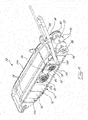
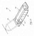
- the figure 1 is an isometric view of an example of an apparatus incorporating according to the proposed concept.
- the apparatus 10 uses a gasoline engine to rotate a track 12 placed around a sealed housing 14 having an elongated shape.
- a sealed housing means that its construction is waterproof but does not exclude the presence of a ventilation circuit of the interior of the housing 14.
- This ventilation circuit comprises at least one air inlet and at least one air outlet.
- the ventilation circuit makes it possible in particular to cool the inside of the casing 14 when its temperature is above an upper limit, for example above 25 ° C. Other values are also possible.
- the rotation of the track 12 around the housing 14 allows the apparatus 10 to move.
- the casing 14 has a lowered shape in order to keep its center of gravity as low as possible.
- the housing 14 includes a side wall 16 on each side.
- the housing 14 may be made of, for example, a metallic or plastic material or both. Aluminum is an example of a possible material for the case 14 because this material is light and strong.
- the track 12 may be made of rubber or another polymer. Other materials are possible.
- the apparatus 10 comprises a handlebar 20 which is connected to the housing 14.
- the handlebar 20 extends substantially towards the rear of the apparatus 10.
- the handlebar 20 is intended to be held and handled by an operator 22 located at the back of the apparatus 10, as shown semi-schematically in the figure 1 .
- the handlebar 20 can be pivoting or fixed, as needed. When pivoting, it is possible to limit the pivoting of the handlebar 20 between a minimum angle and a maximum angle relative to the horizontal.
- the operator 22 may be equipped with skis 24 (or the equivalent) or may be on board a sled coupled to the apparatus 10. As can be seen in FIG. figure 1 the center of gravity of the apparatus 10 is below the height of the operator's knees 22.
- the operator 22 has controls on the handles of the handlebar 20 allowing him especially to control the speed of movement of the apparatus 10 and other functions.
- the controls (not shown) may be connected to the housing 14 using wires and / or wireless communications means.
- Levers for activating a brake may also be provided (see figure 13 ). These levers may be arranged similarly to the brakes of a bicycle or a motorcycle, for example.
- Other elements can be mounted on the handlebar 20 as required, including a lamp, indicator dials, etc.
- the apparatus 10 When it is traveling forwards, the apparatus 10 pulls the operator 22 and, if necessary, moves a payload, such as for example a payload placed aboard a sled coupled to the apparatus
- a payload such as for example a payload placed aboard a sled coupled to the apparatus
- Such an apparatus 10 can easily pull a load equivalent to twice its weight in powdery snow. For example, tests using a 125 km (275 lb) aircraft have shown that such a device could pull a 225 kg (550 lb) load over a distance of 150 km with a single full load. petrol.
- the operator 22 can change the direction of movement of the apparatus 10 by moving the handlebar 20 laterally in the direction opposite to the turn to be made. This action is similar to that done by the operator of a small conventional lawn mower.
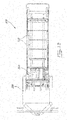
- the figure 2 is a side view of the apparatus 10 shown in FIG. figure 1 .
- the figures 1 and 2 show the assembled apparatus.
- the figure 3 is a view similar to the figure 1 but shows the apparatus 10 without its caterpillar 12 and without the side walls 16 on the sides of its casing 14.
- figure 4 is a view similar to the figure 3 but shows the left side of the apparatus viewed from the rear.
- the figure 5 is a view of the right side of the apparatus 10 shown in the figure 3 .
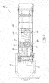
- the housing 14 forms an internal chamber 30 in which are placed different components of the apparatus 10, in particular its gasoline engine 32.
- the housing 14 also has an upper wall 14a, a lower wall 14b, a front wall 14c and a wall rear 14d.
- the casing 14 has a structure of reinforcement, which may include one or more internal walls that can compartmentalize the internal chamber 30. The compartments communicate with each other.
- a pair of upper slides 34 is longitudinally disposed on the upper wall 14a of the housing 14.
- a pair of lower slides similar to that on the top wall 14a, is longitudinally disposed on the bottom wall 14b of the housing 14.
- the Slides are made of a material having a very low coefficient of friction. They allow in particular the track 12 to rotate around the housing 14 and reduce friction between the inner face of the track 12 and the outside of the housing 14. They also serve as guides to keep the track 12 in the axis of the Apparatus 10.
- the slides extend a few centimeters beyond the front and rear ends of the upper and lower walls 14a and 14b to support the track 12 over almost the entire length of the apparatus 10.
- At least one front roller is rotatably mounted in front of the housing 14.
- two front rollers 40 are provided.
- the front rollers 40 are mounted coaxially around a front transverse axis 42, which is supported by a greased internal pin fixed at its ends to two opposite plates 44 arranged parallel to the longitudinal axis of the apparatus 10.
- the plates 44 are rigidly connected to the front of the housing 14.
- a bumper 46 is provided at the front of the apparatus 10. The ends of the bumper 46 are connected to the two plates 44 , as shown in particular in figures 3 and 4 . Sufficient clearance is provided between the interior of the bumper 46 and the front rollers 40 to allow the track 12 to rotate around the housing 14 without hooking the interior of the bumper 46.
- At least one rear roller is rotatably mounted at the rear of the housing 14.
- two rear rollers 50 are provided.
- the rear rollers 50 are coaxially mounted about a rear transverse axis 52, which is supported at its ends by bearings located in two opposing plates 54 arranged parallel to the longitudinal axis of the apparatus 10.
- the plates 54 are connected by rigid manner at the rear of the housing 14.
- a mechanical link is provided between the output shaft of a transmission 60 located in the housing 14 and the rear transverse axis 52.
- the rear rollers 50 are thus used to drive the crawler 12 in rotation in order to be able to move the apparatus 10.
- Different types of mechanical links can be used between the transmission 60 and the transverse rear axle 52.
- the illustrated one comprises a belt 62 or a chain and allows a reduction of the speed of rotation between the output shaft of the transmission 60 and the rear transverse axis 52.
- Other types of links and configurations are also possible.
- the mechanical link between the motor 32 and the transmission 60 is provided by a belt 64.
- the transmission 60 may allow for example forward and reverse. It can have one or more speeds, or be at variable speed.
- the rear transverse axis 52 also supports a brake disk 66, which is shown in FIG. figure 4 .
- the disk is placed near the left end in the example.
- the brake jaws are connected to the housing 14 and can be actuated by the operator 22 from the handlebar 20 (see FIG. figure 13 ).
- the drive motor 32 of the track 12 in the example of Figures 1 to 4 is a gasoline engine placed directly at the front of the transmission 60.
- An intermediate transverse wall is present in the example shown to reinforce the part between the gasoline engine 32 and the transmission 60.
- the gasoline engine 32 is supplied with fuel from a tank 70 located in front of the internal chamber 30 of the apparatus 10.
- a battery 72 is placed next to the fuel tank. This battery 72 serves in particular to power the electric starter of the gasoline engine 32. The operator 22 can thus start and stop the motor 32 without having to access it directly.
- the apparatus 10 Figures 1 to 5 also incorporates a generator 80 placed in the inner chamber 30 and can produce electricity for supplying one or more external equipment to a voltage corresponding in particular to a household power socket, such as for example 110V or 220V / 240V at 60Hz or at 50Hz.
- a generator 80 placed in the inner chamber 30 and can produce electricity for supplying one or more external equipment to a voltage corresponding in particular to a household power socket, such as for example 110V or 220V / 240V at 60Hz or at 50Hz.
- One or more outlets are available on the apparatus 10 or on the generator 80 itself.
- the generator 80 includes an inner rotor rotatable with the same gasoline engine 32.
- the ability to generate electricity from the apparatus 10 can be of great benefit to users such as callers. to use power tools on isolated sites, or cottage owners located far from populated areas. Many other uses can be envisaged.
- a generator having a power of 4000 to 6000W can be installed in an apparatus 10 of the size shown. A smaller or even
- the axis of the generator 80 is disposed transversely to the longitudinal axis of the apparatus 10.
- the generator 80 could also be placed differently in some models. It is connected to the output shaft of the gasoline engine 32 by a transmission belt 82.
- An electric clutch 84 mounted on the generator shaft 80 enables remote activation and deactivation of the mechanical link between the generator and the generator. 32.
- the transmission 60 of the apparatus 10 is set to neutral.
- the intake of fresh air inside the internal chamber 30 of the housing 14 is made by a series of openings 90 provided on at least one side of the housing 14, immediately below the upper wall 14a.
- the openings 90 have a relatively small diameter to allow a reduction in the ingestion of snow and debris, such as twigs or other wood.
- the air passing through the openings 90 enters an inlet box 92 which collects air from all openings 90 on each side of the housing 14.
- the box intake 92 is heated from below by the heat released by the gasoline engine 32 and circulating in the inner chamber 30. This heat keeps the internal chamber 30 well above the freezing point (0 ° C) if the outside temperature is very cold, such as under -20 ° C.
- any particles of snow that enter the intake box 92 can melt and drip outward, even in cold weather.
- the top of the outlet pipe 94 may be raised several millimeters from the bottom of the inlet box 92 to prevent the flow of water directly to the inner chamber 30.
- the figure 6 is a top view of the apparatus 10 shown in FIG. figure 3 .
- the air intake box 92 The air coming out of the intake box 92 then enters into a flexible conduit 95 (schematically illustrated in FIG. figure 4 ) leading to the inlet 33 of the scroll of the cooling fan integrated in the gasoline engine 32.
- the fan in the engine 32 thus generates the suction force required to suck the air through the openings 90.
- the cooling air passes around the cylinder or cylinders of the gasoline engine 32 and then ends within the internal chamber 30.
- the air outlet of the interior of the apparatus 10 is effected in two ways.
- the combustion of gasoline in the engine 32 generates exhaust gases.
- the air used for this combustion is admitted inside the engine 32 from inside the inner chamber 30 or may also come directly from the intake box 92 in the case of certain engines.
- the exhaust gas at the outlet of the cylinder (s) of the engine 32 is then directed towards the rear of the apparatus 10 via an exhaust pipe 96, which is shown at figure 6 .
- the outlet of the exhaust pipe 96 is located in the space 98 where the rear transverse axis 52 and the two rear rollers 50 are located.
- This space 98 is partially obstructed by the presence of the track 12 when the apparatus 10 is assembled.
- This configuration makes it possible in particular to reduce the noise and to avoid any possible contact of the skin or clothing of the operator 22 with the hot outlet of the exhaust pipe 96.
- Other configurations are also possible.
- Air is also vented from the interior of the inner chamber 30 through an air outlet which is part of the ventilation circuit.
- the air passing through the outlet passes firstly through the cooling circuit of the generator 80 and then flows through a flexible conduit 104 (shown schematically in FIG. figure 4 ) to the inlet of an air outlet box 100.
- the outlet box 100 has a construction similar to that of the intake box 92. The air is then discharged through openings 102 placed on the least one side of the housing 14.
- the fan integrated in the generator 80 contributes to the displacement of the air in order to increase the flow of air for its cooling.
- Additional fans placed in series on the flexible conduits connected to the air inlet and outlet can further increase the air flow if the temperature in the inner chamber becomes too high. These fans can be turned on automatically by a thermostat with a temperature sensor or other device.
- the apparatus 10 is configured such that a positive pressure is created in the inner chamber 30. This is accomplished by providing a total air intake area larger than the total exit area. In the example, the number of openings 90 and greater than the number of openings 102. The positive pressure allows in particular to obtain a better seal of the housing 14.
- the underside of the housing 14 is domed at its center. This elevation is about 3 cm at the front and rear of the track 12 in the apparatus 10 shown as an example. This central portion corresponds to about one-third of the length of the apparatus 10. The elevation facilitates in particular the yawing movement during turns as well as the manual pivoting of the apparatus 10 on hard and rough surfaces, such as, for example, asphalt and concrete.
- the front of the bottom wall 14b defines an angle relative to the horizontal. The front transverse axis 42 is thus higher than the rear transverse axis 52. This also facilitates the passage over obstacles.
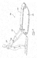
- the figure 7 is a view similar to the figure 1 but in which the operator 22 is standing in a sled 200 coupled to the apparatus 10.
- the hitch 202 of the sled 200 is connected to a support 210 having the shape, in the example shown, of a straight transverse rod or still slightly bent backwards in its center.
- the transverse rod 210 is supported by two corresponding plates 212 projecting upwardly from the housing 14.
- the hitch 202 comprises two sled retaining arms 200, which are attached to a plate 204 which is pivotable about a vertical axis at its end.
- the fastening element 206 can slide from left to right along the transverse rod 210 by means of pulleys placed on each side of the fastening element 206. In a bend, the fastening element 206 can then move towards one of the ends of the transverse rod 210, which facilitates the handling of the apparatus 10 and reduces the effort required on the part of the operator 22.
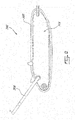
- FIGS. 8 to 13 are similar views to Figures 1 to 6 but show a second example of apparatus 300 in which an electric motor is used.
- This apparatus 300 is otherwise similar to the apparatus 10 of the preceding example.
- the apparatus 300 includes a particular track 302, a sealed case 304 and a handlebar 306, which is held by an operator 308.
- the apparatus 300 may also be used with the sled 200 of the figure 7 .
- the track 302 of the apparatus 300 is rotated with the aid of an electric motor 310 ( figure 10 ).
- This motor 310 is supplied with electricity by one or more batteries 312, also placed in the internal chamber 314 of the housing 304.
- the electric motor 310 can be of AC or DC type, with or without permanent magnets.
- a group of four deep cycle lead batteries 312 is shown in the illustrated example. The number and type of batteries 312 may differ as required.
- the batteries 312 are connected to an electrical controller actuated by the operator 308 from the handles of the handlebar 306. The various electrical connections are not illustrated in the figures to simplify the illustrations.
- the electric motor 310 emits heat.
- This heat represents about 10% of the electrical energy drawn from the batteries 312.
- the heat thus dissipated is used in the internal chamber 314 of the apparatus 300 to keep the batteries 312 warm when the outside temperature is very cold.
- This heat makes it possible to maintain an optimal temperature of the batteries despite the very cold weather.
- the optimum temperature may be for example of the order of 20 to 25 ° C. Other temperatures are also possible.
- the recovery of this heat is beneficial because most batteries lose their efficiency in cold weather. This is particularly the case for lead batteries.
- lead acid batteries remain an attractive choice because they are readily available and relatively inexpensive. They are more resistant to cold than nickel or lithium batteries, for example.
- the efficiency of lead batteries drops almost linearly with temperature, for example from 100% for 25 ° C to 30% for -40 ° C, depending on the exact type of battery. The decrease in efficiency therefore has a direct impact on the autonomy of the device 300. Keeping the heat in the case 304 in cold weather, the batteries 312 can then maintain an efficiency much higher than they would have low temperature.
- the interior of the housing 304 may also be insulated to help conserve heat.
- An internal ventilation system is provided in case of overheating, for example when the apparatus 300 operates in mild weather and the electric motor 310 is highly stressed.
- This internal ventilation system is part of the ventilation system. It can include a thermostat that actuates at least one fan providing an air intake from the outside to dissipate the internal heat.
- the air inlet and the air outlet can be placed at the top of the handlebar 306 at a distance from each other.
- the air then circulates in the pipes forming the sides of the handlebar 306.
- the fan or fans may be placed in the housing 304 or in the handlebar 306.
- the junction between the handlebar 306 and the housing 304 is configured to allow passage air between the two.
- the housing 304 can be built very tightly up to the height of the inlet and the air outlet in the handlebar 306.
- a positive pressure is maintained inside the inner chamber 314 in order to reduce the risk of water infiltration by places that are not fully sealed.
- the apparatus 300 may even then be immersed in a punctual manner, which may be required for example when the apparatus 300 must cross an unfrozen stream or other similar water point.
- a heating element such as a heating cable, inside the housing 304 to keep the batteries 312 warm when charging outdoors in cold weather and also during outdoor storage .
- This support can be installed on one or other of the examples of apparatus 10, 300 presented.
- the support may be useful for transporting equipment, such as a toolbox.
Landscapes
- Engineering & Computer Science (AREA)
- Combustion & Propulsion (AREA)
- Transportation (AREA)
- Mechanical Engineering (AREA)
- Chemical & Material Sciences (AREA)
- Electric Propulsion And Braking For Vehicles (AREA)
- Connection Of Motors, Electrical Generators, Mechanical Devices, And The Like (AREA)
- Arrangement Or Mounting Of Propulsion Units For Vehicles (AREA)
- General Details Of Gearings (AREA)
- Motor Or Generator Frames (AREA)
- Motorcycle And Bicycle Frame (AREA)
- Cooling, Air Intake And Gas Exhaust, And Fuel Tank Arrangements In Propulsion Units (AREA)
- Paper (AREA)
- Automatic Cycles, And Cycles In General (AREA)
- Wind Motors (AREA)
- Rehabilitation Tools (AREA)
Description
Le présent dossier revendique la priorité à la demande de brevet déposée aux États-Unis le
Le domaine technique concerne les appareils de traction compacts pouvant se déplacer sur des terrains difficiles, comme par exemple des terrains recouverts de neige, de sable, de boue, etc.The technical field relates to compact traction devices that can move on difficult terrain, such as land covered with snow, sand, mud, etc.
Plusieurs appareils ont été proposés au fil des années afin de permettre de circuler en terrains difficiles. Parmi ces appareils, plusieurs concernent des appareils compacts permettant une propulsion ou une traction d'une personne, notamment d'un skieur, à l'aide d'une chenille entraînée en rotation par un moteur. On en trouve des exemples dans les documents
profonde pour permettre la présence d'une motoneige. Un autre avantage de ces appareils est que leur transport dans un autre véhicule est beaucoup plus simple et facile que dans le cas d'un véhicule plus gros et plus lourd, comme par exemple une motoneige.Several devices have been proposed over the years to allow driving in difficult terrain. Among these devices, several relate to compact devices for propelling or pulling a person, including a skier, with a caterpillar driven in rotation by a motor. Examples can be found in the documents
deep to allow the presence of a snowmobile. Another advantage of these devices is that their transport in another vehicle is much simpler and easier than in the case of a larger and heavier vehicle, such as a snowmobile.
Malheureusement, aucun des appareils proposés antérieurement ne s'est révélé être entièrement bien adapté aux conditions hivernales très rigoureuses que l'on peut retrouver à certaines périodes de l'année dans les endroits où ces appareils sont susceptibles d'être utiles. Par exemple, une température très froide peut réduire considérablement la fiabilité et l'autonomie d'un appareil muni d'un moteur électrique alimenté par des batteries. Dans le cas d'un moteur à essence, la combinaison du froid extérieur et de la chaleur dégagée par le moteur peut occasionner des accumulations de glace et de neige compactée à des endroits sensibles de l'appareil. De plus, les températures moins froides sont davantage susceptibles d'occasionner des infiltrations d'eau dans l'appareil et ainsi causer des pannes qui peuvent être difficile à réparer, surtout lorsqu'elles surviennent dans des endroits loin en forêt ou dans d'autres endroits difficiles d'accès.Unfortunately, none of the aircraft previously proposed has been shown to be fully adapted to the very harsh winter conditions that can be found at certain times of the year in areas where these devices are likely to be useful. For example, a very cold temperature can significantly reduce the reliability and battery life of a battery-powered electric motor. In the case of a gasoline engine, the combination of outside cold and engine heat can cause accumulations of ice and compacted snow in sensitive areas of the aircraft. In addition, cooler temperatures are more likely to cause water seepage into the unit and cause breakdowns that can be difficult to repair, especially when they occur in places far away in the forest or other areas. hard to reach places.
Les appareils proposés antérieurement ne permettent pas non plus de transporter facilement un générateur électrique à des endroits difficiles d'accès.The devices previously proposed also do not allow to easily transport an electric generator in hard to reach places.
Il est donc clair que des améliorations dans le domaine technique concerné sont encore nécessaires.It is therefore clear that improvements in the technical field concerned are still needed.
Selon l'invention il est proposé un appareil de traction compact inclut : un boîtier étanche de forme allongée s'étendant dans un axe longitudinal et définissant une chambre interne, le boîtier ayant une paroi supérieure et une paroi inférieure; une chenille disposée autour du boîtier selon son axe longitudinal et permettant à l'appareil de se mouvoir lorsque la chenille est entraînée en rotation autour du boîtier; un guidon relié au boîtier et s'étendant substantiellement vers l'arrière, caractérisé en ce qu'il inclut : un générateur placé dans la chambre interne du boîtier et servant à produire de l'électricité pouvant alimenter un équipement externe; et un moteur à essence servant à sélectivement entraîner la chenille en rotation et à faire tourner le générateur, le moteur étant situé dans la chambre interne du boîtier.According to the invention there is provided a compact traction apparatus including: an elongate sealed housing extending in a longitudinal axis and defining an inner chamber, the housing having an upper wall and a lower wall; a crawler disposed around the housing along its longitudinal axis and allowing the apparatus to move when the crawler is rotated around the housing; a handlebar connected to the housing and extending substantially rearward, characterized in that it includes: a generator placed in the inner chamber of the housing and for generating electricity that can power an external equipment; and a gasoline engine for selectively driving the track in rotation and rotating the generator, the engine being located in the inner chamber of the housing.
-
La
figure 1 est une vue isométrique d'un exemple d'un appareil réalisé selon le concept proposé;Thefigure 1 is an isometric view of an example of an apparatus made according to the proposed concept; -
La
figure 2 est une vue de côté de l'appareil montré à lafigure 1 ;Thefigure 2 is a side view of the device shown at thefigure 1 ; -
La
figure 3 est une vue similaire à lafigure 1 mais montre l'appareil sans sa chenille et sans les parois latérales sur les côtés de son boîtier;Thefigure 3 is a view similar to thefigure 1 but shows the apparatus without its caterpillar and without the side walls on the sides of its case; -
La
figure 4 est une vue similaire à lafigure 3 mais montre le côté gauche de l'appareil vu de l'arrière;Thefigure 4 is a view similar to thefigure 3 but shows the left side of the camera from the back; -
La
figure 5 est une vue du côté droit de l'appareil montré à lafigure 3 ;Thefigure 5 is a view from the right side of the device shown at thefigure 3 ; -
La
figure 6 est une vue du dessus de l'appareil montré à lafigure 3 ;Thefigure 6 is a top view of the device shown at thefigure 3 ; -
La
figure 7 est une vue similaire à lafigure 1 mais dans laquelle l'opérateur est debout dans un traîneau attelé à l'appareil; etThefigure 7 is a view similar to thefigure 1 but in which the operator is standing in a sled coupled to the apparatus; and -
Les
figures 8 à 13 sont des vues similaires auxfigures 1 à 6 mais montrent un deuxième exemple d'appareil dans lequel un moteur électrique est utilisé.TheFigures 8 to 13 are similar views toFigures 1 to 6 but show a second example of apparatus in which an electric motor is used.
La
La rotation de la chenille 12 autour du boîtier 14 permet à l'appareil 10 de se mouvoir. Le boîtier 14 a une forme surbaissée afin de garder son centre de gravité le plus bas possible. Le boîtier 14 comprend une paroi latérale 16 de chaque côté. Le boîtier 14 peut être fait par exemple d'un matériau métallique, plastique ou les deux. L'aluminium est un exemple d'un matériau possible pour le boîtier 14 car ce matériau est léger et résistant. La chenille 12 peut être faite de caoutchouc ou d'un autre polymère. D'autres matériaux sont possibles.The rotation of the
L'appareil 10 comprend un guidon 20 qui est relié au boîtier 14. Le guidon 20 s'étend substantiellement vers l'arrière de l'appareil 10. Le guidon 20 est destiné à être tenu et manipulé par un opérateur 22 situé à l'arrière de l'appareil 10, tel qu'illustré de façon semi-schématique à la
L'opérateur 22 peut être équipé de skis 24 (ou l'équivalent) ou encore être à bord d'un traîneau attelé à l'appareil 10. Comme on peut le constater à la
L'opérateur 22 dispose de contrôles sur les poignées du guidon 20 lui permettant notamment de contrôler la vitesse de déplacement de l'appareil 10 et d'autres fonctions. Les contrôles (non illustrés) peuvent être reliés au boîtier 14 à l'aide de fils et/ou de moyens de communications sans fil. Selon le modèle, il est notamment possible de prévoir un dispositif permettant à l'appareil 10 de reculer par la force de son moteur, ce qui peut s'avérer très utile dans certaines circonstances. Des leviers permettant d'activer un frein peuvent aussi être prévus (voir la
Lorsqu'il circule vers l'avant, l'appareil 10 tire l'opérateur 22 et, s'il y a lieu, déplace une charge utile, comme par exemple une charge utile placée à bord d'un traîneau attelé à l'appareil 10. Un tel appareil 10 peut facilement tirer une charge équivalente à deux fois son poids dans de la neige poudreuse. Par exemple, des tests effectués à l'aide d'un appareil de 125 km (275 1b) ont démontrés qu'un tel appareil pouvait tirer une charge de 225 kg (550 1b) sur une distance de 150 km avec un seul plein d'essence.When it is traveling forwards, the
L'opérateur 22 peut modifier la direction de déplacement de l'appareil 10 en bougeant latéralement le guidon 20 dans la direction opposée au virage à effectuer. Cette action est similaire à celle faite par l'opérateur d'une petite tondeuse à gazon conventionnelle.The
La
Comme on peut le voir en particulier aux
Une paire de glissières supérieures 34 est disposée de façon longitudinale sur la paroi supérieure 14a du boîtier 14. Une paire de glissières inférieures, similaire à celle sur la paroi supérieure 14a, est disposée de façon longitudinale sur la paroi inférieure 14b du boîtier 14. Les glissières sont faites d'un matériau ayant un coefficient de friction très bas. Elles permettent notamment à la chenille 12 de tourner autour du boîtier 14 et de réduire la friction entre la face intérieure de la chenille 12 et l'extérieur du boitier 14. Elles servent aussi de guides pour garder la chenille 12 dans l'axe de l'appareil 10. Les glissières s'étendent sur quelques centimètres au-delà des extrémités avant et arrière des parois supérieure 14a et inférieure 14b afin de supporter la chenille 12 sur presque toute la longueur de l'appareil 10.A pair of
Au moins un rouleau avant est monté en rotation à l'avant du boîtier 14. Dans l'exemple illustré, deux rouleaux avant 40 sont prévus. Les rouleaux avant 40 sont montés coaxialement autour d'un axe transversal avant 42, lequel est supporté par un axe interne graissé fixé à ses extrémités à deux plaques opposées 44 disposées parallèlement à l'axe longitudinal de l'appareil 10. Les plaques 44 sont reliées de façon rigide à l'avant du boîtier 14. Également dans l'exemple illustré, un pare-chocs 46 est prévu tout à l'avant de l'appareil 10. Les extrémités du pare-chocs 46 sont reliées aux deux plaques 44, tel que montré notamment aux
Au moins un rouleau arrière est monté en rotation à l'arrière du boîtier 14. Dans l'exemple illustré, deux rouleaux arrière 50 sont prévus. Les rouleaux arrière 50 sont montés coaxialement autour d'un axe transversal arrière 52, lequel est supporté à ses extrémités par des roulements situés dans deux plaques opposées 54 disposées parallèlement à l'axe longitudinal de l'appareil 10. Les plaques 54 sont reliées de façon rigide à l'arrière du boîtier 14. Également dans l'exemple illustré, un lien mécanique est prévu entre l'arbre de sortie d'une transmission 60 située dans le boîtier 14 et l'axe transversal arrière 52. Les rouleaux arrière 50 sont donc utilisés pour entraîner la chenille 12 en rotation afin de pouvoir déplacer l'appareil 10. Différents types de liens mécaniques peuvent être utilisés entre la transmission 60 et l'axe transversal arrière 52. Celui qui est illustré comprend une courroie 62 ou une chaîne et permet une réduction de la vitesse de rotation entre l'arbre de sortie de la transmission 60 et l'axe transversal arrière 52. D'autres types de liens et configurations sont également possibles. Le lien mécanique entre le moteur 32 et la transmission 60 est assuré par une courroie 64. La transmission 60 peut permettre par exemple la marche avant et arrière. Elle peut avoir un ou encore plusieurs vitesses, ou bien être à vitesse variable.At least one rear roller is rotatably mounted at the rear of the
L'axe transversal arrière 52 supporte également un disque de frein 66, lequel est montré à la
Le moteur d'entraînement 32 de la chenille 12 dans l'exemple des
L'appareil 10 des
L'axe du générateur 80 est disposé transversalement à l'axe longitudinal de l'appareil 10. Le générateur 80 pourrait aussi être placé autrement dans certains modèles. Il est relié à l'arbre de sortie du moteur à essence 32 par une courroie de transmission 82. Un embrayage électrique 84 monté sur l'arbre du générateur 80 permet d'activer et de désactiver à distance le lien mécanique entre le générateur et le moteur à essence 32. Ainsi, lorsque le générateur 80 n'a pas à être utilisé, comme par exemple lorsque l'appareil 10 est en déplacement, la rotation inutile du rotor du générateur 80 peut être évitée. Lorsque le générateur 80 est en fonction, la transmission 60 de l'appareil 10 est mise au neutre.The axis of the
L'admission d'air neuf à l'intérieur de la chambre interne 30 du boîtier 14 se fait par une série d'ouvertures 90 prévues sur au moins un côté du boîtier 14, immédiatement sous la paroi supérieure 14a. Les ouvertures 90 ont un diamètre relativement petit afin de permettre une diminution de l'ingestion de neige et de débris, comme par exemple des brindilles de bois ou autre. L'air qui passe par les ouvertures 90 entre dans une boîte d'admission 92 qui collecte l'air provenant de toutes les ouvertures 90 de chaque côté du boîtier 14. Lors de l'utilisation de l'appareil 10, la boîte d'admission 92 est chauffée par le dessous grâce à la chaleur dégagée par le moteur à essence 32 et qui circule dans la chambre interne 30. Cette chaleur permet de garder la chambre interne 30 bien au-dessus du point de congélation (0°C) même si la température extérieure est très froide, comme par exemple sous le -20°C. Grâce à cette chaleur, toute particule de neige qui entre dans la boîte d'admission 92 peut fondre et s'égoutter vers l'extérieur, et ce, même par temps froid. L'air sort de la boîte d'admission 92 par un tuyau de sortie 94 qui est circulaire dans l'exemple. Le haut du tuyau de sortie 94 peut être surélevé de plusieurs millimètres par rapport au fond de la boîte d'admission 92 afin d'éviter l'écoulement de l'eau directement vers la chambre interne 30.The intake of fresh air inside the
La
La sortie de l'air de l'intérieur de l'appareil 10 s'effectue de deux façons. D'une part, la combustion de l'essence dans le moteur 32 génère des gaz d'échappement. L'air servant à cette combustion est admis à l'intérieur du moteur 32 à partir de l'intérieur de la chambre interne 30 ou peut aussi provenir directement de la boîte d'admission 92 dans le cas de certains moteurs. Les gaz d'échappement à la sortie du ou des cylindres du moteur 32 sont ensuite dirigés vers l'arrière de l'appareil 10 par un tuyau d'échappement 96, lequel est montré à la
De l'air est aussi évacué de l'intérieur de la chambre interne 30 par une sortie d'air qui fait partie du circuit de ventilation. L'air passant par la sortie traverse tout d'abord par le circuit de refroidissement du générateur 80 et circule ensuite par un conduit flexible 104 (représenté de façon schématique à la
Lorsque le générateur 80 est en fonction, le ventilateur intégré au générateur 80 contribue au déplacement de l'air afin d'augmenter le débit d'air pour son refroidissement. Des ventilateurs additionnels placés en série sur les conduits flexibles reliés à l'entrée et à la sortie d'air peuvent permettent d'augmenter davantage la circulation d'air si la température dans la chambre interne 30 devient trop élevée. Ces ventilateurs peuvent être mis en marche automatiquement grâce à un thermostat muni d'une sonde de température ou d'un autre dispositif.When the
L'appareil 10 est configuré de telle sorte qu'une pression positive est créée dans la chambre interne 30. Cela est réalisé en prévoyant une surface totale d'admission de l'air plus grande que la surface totale de sortie. Dans l'exemple, le nombre d'ouvertures 90 et plus grand que le nombre d'ouvertures 102. La pression positive permet notamment d'obtenir une meilleure étanchéité du boîtier 14.The
Lorsque l'appareil 10 est en mouvement, les côtés du boîtier 14 sont fermés de façon étanche à l'aide des parois latérales 16, lesquelles sont montrées aux
Tel qu'il est montré à la
La
Les
La chenille 302 de l'appareil 300 est entraînée en rotation à l'aide d'un moteur électrique 310 (
En cours d'utilisation, le moteur électrique 310 dégage de la chaleur. Cette chaleur représente environ 10% de l'énergie électrique puisée dans les batteries 312. La chaleur ainsi dissipée est utilisée dans la chambre interne 314 de l'appareil 300 pour tenir au chaud les batteries 312 lorsque la température extérieure est très froide. Cette chaleur permet alors de conserver une température optimale des batteries malgré le temps très froid. La température optimale peut être par exemple de l'ordre de 20 à 25°C. D'autres températures sont aussi possibles. La récupération de cette chaleur est bénéfique car la plupart des batteries perdent leur efficacité par temps froid. C'est notamment le cas des batteries au plomb. Bien que des types de batteries plus performantes existent, les batteries au plomb demeure un choix intéressant parce qu'elles sont facilement disponibles et relativement peu dispendieuses. Elles résistent mieux au froid que des batteries au nickel ou au lithium, par exemple. L'efficacité des batteries au plomb baisse cependant de façon presque linéaire en fonction de la température, passant par exemple de 100% pour 25°C à 30% pour -40°C, selon le type exact de batterie. La baisse d'efficacité a donc une incidence directe sur l'autonomie de l'appareil 300. En gardant la chaleur dans le boîtier 304 par temps froid, les batteries 312 peuvent alors conserver une efficacité nettement supérieure à celle qu'elles auraient à basse température. L'intérieur du boîtier 304 peut aussi être isolé pour aider à conserver la chaleur.In use, the
Un système interne de ventilation est prévu en cas de surchauffe, par exemple lorsque l'appareil 300 opère par temps doux et que le moteur électrique 310 est très sollicité. Ce système interne de ventilation fait partie du circuit de ventilation. Il peut comprendre un thermostat qui actionne au moins un ventilateur assurant un apport d'air de l'extérieur afin de dissiper la chaleur interne. L'entrée d'air et la sortie d'air peuvent être placées dans le haut du guidon 306 à une certaine distance l'un de l'autre. L'air circule alors dans les tuyaux formant les côtés du guidon 306. Le ou les ventilateurs peuvent être placés dans le boîtier 304 ou encore dans le guidon 306. La jonction entre le guidon 306 et le boîtier 304 est configurée afin de permettre un passage de l'air entre les deux. Ainsi, le boîtier 304 peut être construit de façon très étanche jusqu'à la hauteur de l'entrée et de la sortie d'air dans le guidon 306. Une pression est positive est maintenue à l'intérieur de la chambre interne 314 afin de réduire les risques d'infiltration d'eau par des endroits qui ne seraient pas entièrement bien scellés. L'appareil 300 pourra même alors être immergé de façon ponctuelle, ce qui peut être requis par exemple lorsque l'appareil 300 doit franchir un ruisseau non gelé ou un autre point d'eau similaire.An internal ventilation system is provided in case of overheating, for example when the
Il est possible d'incorporer un élément chauffant, comme par exemple un câble chauffant, à l'intérieur du boîtier 304 afin de garder les batteries 312 au chaud lors de leur charge à l'extérieur par temps froid et aussi lors de leur entreposage extérieur.It is possible to incorporate a heating element, such as a heating cable, inside the
Il est également possible de prévoir un support fixe placé au-dessus de la chenille 302. Ce support peut être installé sur l'un ou l'autre des exemples d'appareils 10, 300 présentés. Le support peut être utile pour transporter de l'équipement, comme par exemple une boîte à outils.It is also possible to provide a fixed support placed above the
Claims (14)
- A compact pulling apparatus (10), including:a watertight elongate housing (14) extending along a longitudinal axis and defining an inner chamber (30), the housing (14) including a top wall (14a) and a bottom wall (14b);a handlebar (20) connected to the housing (14) and extending substantially rearward;a track (12) disposed around the housing (14) along its longitudinal axis and enabling the apparatus (10) to move when the track (12) is rotatably driven around the housing (14);a gasoline engine (32) located within the inner chamber (30) of the housing (14);characterized in that:the apparatus (10) includes a generator (80) located within the inner chamber (30) of the housing (14) to produce electricity which can power an external equipment; andthe gasoline engine (32) is provided to selectively rotatably drive the track (12) and the generator (80).
- The apparatus (10) according to claim 1, characterized in that it includes:a pair of top skids (34) disposed longitudinally on the top wall (14a) of the housing (14);a pair of bottom skids disposed longitudinally on the bottom wall (14b) of the housing (14);at least one front roller (42) rotatably connected at the front of the housing (14);at least one rear roller (50) rotatably connected at the rear of the housing (14); andthe track (12) includes an inner face which is supported by the skids (34) and the rollers (42, 50).
- The apparatus (10) according to claim 2, characterized in that it includes a transmission (60) forming at least part of the mechanical connection between the engine (32) and the track (12).
- The apparatus (10) according to claim 3, characterized in that the transmission (60) is mechanically connected to the rear roller (50).
- The apparatus (10) according to any one of claims 1 to 4, characterized in that the generator (80) produces electricity at a voltage corresponding to that of a domestic power outlet.
- The apparatus (10) according to any one of claims 1 to 5, characterized in that the generator (80) has a rotation axis disposed transversely with reference to the longitudinal axis of the housing (14).
- The apparatus (10) according to claim 5 or 6, characterized in that the internal rotor of the generator (80) and the gasoline engine (32) are mechanically connected through an electric clutch (84).
- The apparatus (10) according to any one of claims 1 to 7, characterized in that the inner chamber (30) is maintained at a positive pressure with reference to the atmospheric pressure.
- The apparatus (10) according to any one of claims 1 to 8, characterized in that the housing (14) includes detachable lateral walls (16).
- The apparatus (10) according to any one of claims 1 to 9, characterized in that the apparatus (10) includes a support (210) intended to receive one end of a hitch (202) for a sled (200).
- The apparatus (10) according to claim 10, characterized in that the support (210) includes a transversal strut (210) connected to the top of the housing (14).
- The apparatus (10) according to claim 11, characterized in that the transversal strut (210) and the end of the hitch (202) are slidably connected.
- The apparatus (10) according to any one of claims 1 to 12, characterized in that it includes a heating element provided within the inner chamber (30) that can be powered using electricity from the outside in order to maintain a minimum temperature when the apparatus (10) is not in use.
- The apparatus (10) according to any one of claims 1 to 13, characterized in that the apparatus (10) includes at least one of the following features: a brake (66) which can be operated from the handlebar (20), and the housing (14) of the apparatus (10) is made at least in part of aluminum.
Applications Claiming Priority (2)
| Application Number | Priority Date | Filing Date | Title |
|---|---|---|---|
| US34253810P | 2010-04-15 | 2010-04-15 | |
| EP11768347.4A EP2558353B1 (en) | 2010-04-15 | 2011-04-15 | Compact pulling apparatus |
Related Parent Applications (1)
| Application Number | Title | Priority Date | Filing Date |
|---|---|---|---|
| EP11768347.4A Division EP2558353B1 (en) | 2010-04-15 | 2011-04-15 | Compact pulling apparatus |
Publications (2)
| Publication Number | Publication Date |
|---|---|
| EP2946990A1 EP2946990A1 (en) | 2015-11-25 |
| EP2946990B1 true EP2946990B1 (en) | 2018-06-06 |
Family
ID=44798233
Family Applications (2)
| Application Number | Title | Priority Date | Filing Date |
|---|---|---|---|
| EP15175197.1A Not-in-force EP2946990B1 (en) | 2010-04-15 | 2011-04-15 | Compact pulling apparatus |
| EP11768347.4A Active EP2558353B1 (en) | 2010-04-15 | 2011-04-15 | Compact pulling apparatus |
Family Applications After (1)
| Application Number | Title | Priority Date | Filing Date |
|---|---|---|---|
| EP11768347.4A Active EP2558353B1 (en) | 2010-04-15 | 2011-04-15 | Compact pulling apparatus |
Country Status (19)
| Country | Link |
|---|---|
| US (2) | US8453769B2 (en) |
| EP (2) | EP2946990B1 (en) |
| JP (3) | JP5870399B2 (en) |
| KR (2) | KR101847660B1 (en) |
| CN (2) | CN104802869B (en) |
| BR (1) | BR112012026245B1 (en) |
| CA (3) | CA2776417C (en) |
| DK (1) | DK2558353T3 (en) |
| ES (1) | ES2549437T3 (en) |
| HK (2) | HK1179226A1 (en) |
| HR (1) | HRP20151066T1 (en) |
| HU (1) | HUE026462T2 (en) |
| MX (1) | MX2012011442A (en) |
| PL (1) | PL2558353T3 (en) |
| PT (1) | PT2558353E (en) |
| RS (1) | RS54327B1 (en) |
| SI (1) | SI2558353T1 (en) |
| SM (1) | SMT201500243B (en) |
| WO (1) | WO2011127607A1 (en) |
Families Citing this family (17)
| Publication number | Priority date | Publication date | Assignee | Title |
|---|---|---|---|---|
| US9821865B2 (en) | 2010-04-15 | 2017-11-21 | Yvon Martel | Compact pulling apparatus |
| US8827014B2 (en) | 2010-04-15 | 2014-09-09 | Yvon Martel | Compact pulling apparatus |
| EP2946990B1 (en) | 2010-04-15 | 2018-06-06 | Yvon Martel | Compact pulling apparatus |
| SI2908918T1 (en) * | 2012-10-19 | 2019-05-31 | Yvon Martel | Compact drive unit including juxtaposed tracks |
| US20140262577A1 (en) * | 2013-03-12 | 2014-09-18 | William M. Ambrisco | Towing system |
| CN103158796B (en) * | 2013-03-15 | 2015-05-20 | 黄刚 | Continuous track walking mechanism |
| SE538232C2 (en) * | 2013-05-08 | 2016-04-12 | BAE Systems Hägglunds Aktiebolag | Drive unit for tracked vehicles and vehicles equipped with drive unit |
| EP3019389A4 (en) * | 2013-07-11 | 2016-07-13 | Yvon Martel | Compact pulling apparatus |
| ES2486590B1 (en) * | 2014-02-14 | 2015-05-26 | Alfredo ZUFIAUR FERNÁNDEZ DE BETOÑO | Snow Plow |
| NO339366B1 (en) * | 2015-03-12 | 2016-12-05 | Rottefella As | System for optional dynamic positioning of a ski binding |
| CN108245870B (en) * | 2016-12-29 | 2020-04-10 | 厦门扬恩科技有限公司 | Novel take skis of manual brake |
| US10464383B2 (en) | 2017-01-03 | 2019-11-05 | John Burnett Coast | Amphibious transport system |
| JP2018127183A (en) * | 2017-02-10 | 2018-08-16 | 株式会社 神崎高級工機製作所 | Crawler drive device and crawler type travel device |
| CA3055786A1 (en) * | 2017-03-10 | 2018-09-13 | Roshell Industries Incorporated | Tracked personal snow transport system |
| CA2987210A1 (en) * | 2017-11-30 | 2019-05-30 | Yvon Martel | Steerable coupling linkage for a compact pulling apparatus |
| JP6827436B2 (en) * | 2018-03-12 | 2021-02-10 | ヤンマーパワーテクノロジー株式会社 | Crawler traveling device |
| US11174608B1 (en) * | 2021-04-02 | 2021-11-16 | Mary Margaret Sullivan | Power-assisted ski track setter system |
Family Cites Families (90)
| Publication number | Priority date | Publication date | Assignee | Title |
|---|---|---|---|---|
| US1317103A (en) | 1919-09-23 | Emile rimailho | ||
| US758757A (en) | 1904-01-30 | 1904-05-03 | William R Jones | Traction-engine. |
| US1287261A (en) | 1917-08-28 | 1918-12-10 | Lester B Domer | Tractor. |
| GB140121A (en) | 1917-12-26 | 1920-03-25 | Cie Forges Et Acieries Marine | Improvements in or relating to endless track or belt rail tractor vehicles |
| US2046560A (en) | 1933-09-09 | 1936-07-07 | Neafie J Buck | Tractor |
| US2196458A (en) | 1937-10-22 | 1940-04-09 | Theodore P Flynn | Snow tractor |
| US2289768A (en) | 1940-11-22 | 1942-07-14 | John Fehrenbacher | Snow sled |
| US2345496A (en) | 1941-07-03 | 1944-03-28 | Alvin W Opheim | Tractor |
| US2393309A (en) | 1943-04-16 | 1946-01-22 | Avery M Cochran | Snow tractor |
| US2519745A (en) | 1947-02-24 | 1950-08-22 | Vincent A Danielson | Garden tractor |
| US2702088A (en) | 1951-08-31 | 1955-02-15 | Jr Marcel Klimek | Snowmobile |
| US2855059A (en) | 1956-07-13 | 1958-10-07 | Sidney S Sutherland | Self-propelled endless tread snow tractor |
| FR1169880A (en) | 1958-01-13 | 1959-01-07 | Individual skier thruster | |
| US3146840A (en) | 1959-07-13 | 1964-09-01 | Walsh Jack | Powered endless track snow sled |
| US3231036A (en) | 1961-05-15 | 1966-01-25 | Appenrodt Richard | Stair climbing invalid carriages |
| US3068950A (en) | 1961-10-10 | 1962-12-18 | Isaac F Davidson | Adjustable motor-driven invalid chair with endless tracks |
| US3221830A (en) | 1961-12-14 | 1965-12-07 | Walsh Jack | Cross-country snow vehicle |
| GB1042943A (en) | 1963-03-12 | 1966-09-21 | Pierre Antonetti | Track laying tractor for towing a skier |
| US3269475A (en) | 1963-11-19 | 1966-08-30 | Duramobile Company | Transportation system having two pairs of endless tracks |
| US3398806A (en) | 1966-05-12 | 1968-08-27 | Alvin L. Hendricks | Self-propelled crawler-type mobile platform |
| US3427078A (en) * | 1966-10-20 | 1969-02-11 | Frederick L Parsons | Endless track with hollow inflatable treads |
| US3418961A (en) * | 1967-03-17 | 1968-12-31 | Gregg Gibson & Gregg Inc | Swamp clearing machine |
| JPS4843545Y1 (en) * | 1967-04-06 | 1973-12-15 | ||
| FR1568862A (en) | 1968-01-09 | 1969-05-30 | ||
| US3590523A (en) | 1968-07-02 | 1971-07-06 | Mathias H Riesgraf | Toy vehicle with track drive mechanism having an internal power source |
| US3610355A (en) | 1969-04-28 | 1971-10-05 | Buck Willard | Portable snow vehicle |
| US3554300A (en) * | 1969-05-28 | 1971-01-12 | Edgar N Rosenberg | Deep submergence tunneling device |
| US3645348A (en) | 1969-05-29 | 1972-02-29 | Husted Royce Hill | Power ski |
| JPS4828216Y1 (en) * | 1970-03-24 | 1973-08-23 | ||
| US3734221A (en) | 1971-06-04 | 1973-05-22 | R Labelle | Endless track vehicle |
| US3750777A (en) * | 1972-04-07 | 1973-08-07 | R Thompson | Propulsion unit for skier |
| US3809173A (en) | 1972-08-21 | 1974-05-07 | Leod D Mc | Ski propelling device |
| US3826323A (en) | 1973-04-12 | 1974-07-30 | A Mehne | Propelling apparatus for skiers |
| US3853192A (en) | 1973-10-09 | 1974-12-10 | Saroy Eng | Power driven ski |
| US3964560A (en) | 1975-02-20 | 1976-06-22 | Saroy Engineering | Power driven ski |
| US4175627A (en) | 1975-07-25 | 1979-11-27 | Saroy Engineering | Propulsion system for a snow going device |
| US4096919A (en) * | 1976-09-02 | 1978-06-27 | Thompson Richard G | Propulsion unit for skiers |
| US4102292A (en) * | 1976-10-05 | 1978-07-25 | Hunter Ralph W | Amphibious vehicle |
| US4146101A (en) | 1976-11-16 | 1979-03-27 | Aime Plourde | Snow cycle vehicle |
| FR2431304A1 (en) * | 1978-07-18 | 1980-02-15 | Jaulmes Eric | Outboard motor for propelling skier uphill - has motor surrounded by endless track and arms joined by strap to push user |
| US4257652A (en) | 1978-11-20 | 1981-03-24 | Edwards Charles R | Device for transporting materials across fragile structures |
| FR2450191A1 (en) | 1979-03-02 | 1980-09-26 | Maydieu Jacques | Tracked, stair-negotiating Vehicle - is driven by two independent notched tracks and has platform tilting to remain horizontal |
| US4421193A (en) | 1981-01-05 | 1983-12-20 | Bissett Fred L | Tread powered ski |
| US4433634A (en) * | 1982-02-05 | 1984-02-28 | Coast Machinery, Inc. | Tracked, amphibious vehicle with track securement and guide means |
| IT1155528B (en) | 1982-04-14 | 1987-01-28 | Giovanni Allisio | SELF-PROPELLED GROUP SUITABLE FOR COMMANDING THE ADVANCE ON A SNOW COVERED ROUTE OF A PERSON WITH SNOW SKIING |
| US4519470A (en) | 1983-03-29 | 1985-05-28 | Giovanni Allisio | Self-propelled unit for propelling a person wearing snow skis along a rising snow path |
| US4548315A (en) * | 1983-06-07 | 1985-10-22 | Dravo Corporation | Tethered vehicle for moving bulk material |
| GB8321783D0 (en) | 1983-08-12 | 1983-09-14 | Armstrong P D | Ski lift |
| JPH0320236Y2 (en) * | 1986-05-30 | 1991-04-30 | ||
| JPS6353185A (en) | 1986-06-03 | 1988-03-07 | エドワ−ド ウイリアム サザ−ランド ニ−ボ−ン | Improved self-propelling type caddie |
| FR2604367B1 (en) | 1986-09-26 | 1988-12-23 | Imberteche Rene | DEVICE FOR ELECTRICAL ASSISTANCE TO THE DIFFERENT FUNCTIONS OF A UNIVERSAL SKI |
| CA1293757C (en) | 1988-02-09 | 1991-12-31 | Bronislaw Kadela | All terrain off road vehicle |
| US4984648A (en) | 1988-12-21 | 1991-01-15 | Michael Strzok | Motorized skiboard |
| FR2651201B1 (en) | 1989-08-31 | 1991-10-25 | Framatome Sa | VEHICLE WITH INCLINABLE TRACKS. |
| FR2664225A1 (en) | 1990-07-09 | 1992-01-10 | Framatome Sa | MOTORIZED PROPELLER VEHICLE. |
| FR2673545B1 (en) | 1991-03-07 | 1993-06-04 | Lembardo Guillaume | SKIS OR MONO-SKI EQUIPPED WITH MOTORIZED LIFT TRACKS AND RETRACTABLE GUIDE BLADES. |
| US5181478A (en) * | 1991-12-23 | 1993-01-26 | Sebastiano Berardi | Amphibious vehicle with retractable wheels |
| IT229127Y1 (en) | 1992-01-27 | 1998-06-24 | Nunziato Bianco | AUTOMATED TROLLEY FOR THE TRANSPORT AND THE ASCENT OF ONE OR MORE PEOPLE ON THE SNOW AND ICE AS WELL AS SLEED MOTORCYCLES EQUIPPED WITH FOUR |
| FR2688701A1 (en) | 1992-03-23 | 1993-09-24 | Martinez Michel | Snowboard propelled by a thermal (heat) motor and a caterpillar track |
| AU3861493A (en) | 1992-06-04 | 1993-12-09 | Johannes Ulrich Minder | Mobile controllable device |
| US5363937A (en) * | 1992-10-19 | 1994-11-15 | Lmc Operating Corp. | Battery operated tracked vehicle |
| WO1994015683A1 (en) | 1993-01-15 | 1994-07-21 | Pedro Salcedo Garcia | Autonomous transporter for skiers |
| US5662186A (en) | 1993-12-20 | 1997-09-02 | Welch; Mark C. | Power-Driven Snowboard |
| DE4409677A1 (en) | 1994-03-17 | 1994-08-11 | Klapproth Ernst Peter | Motorised sledge |
| CA2135653A1 (en) | 1995-03-28 | 1996-09-29 | Andre Morneau | Skidoo |
| CA2237776A1 (en) | 1995-11-17 | 1997-05-29 | Harry E. Dempster | Portable, power-drive unit and accessory attachment |
| JP3016507B2 (en) * | 1996-02-22 | 2000-03-06 | 本田技研工業株式会社 | Crawler truck |
| US5799743A (en) | 1997-01-24 | 1998-09-01 | Inuktun Services Ltd. | Drive system |
| SK283293B6 (en) * | 1997-06-24 | 2003-05-02 | Comi, Spol. S R.O. | Self-propelling device |
| US6408962B1 (en) | 2000-04-21 | 2002-06-25 | Jason Ryckman | Convertible sled for transporting large game |
| US6725959B1 (en) | 2001-12-20 | 2004-04-27 | Raymond Shea | Motorized snow board vehicle |
| GB2390837B (en) | 2002-07-02 | 2006-01-11 | Snowdome Ltd | Snowmobiles |
| US6880651B2 (en) * | 2003-05-14 | 2005-04-19 | Singapore Technologies Kinetics Ltd. | Articulated vehicle, an articulation device and a drive transmission |
| DE20316238U1 (en) | 2003-10-20 | 2003-12-18 | Dorma Gmbh + Co. Kg | Fitting for an all-glass door |
| JP2006123595A (en) * | 2004-10-26 | 2006-05-18 | Yamaha Motor Co Ltd | Snowmobile |
| US7131507B2 (en) * | 2005-01-14 | 2006-11-07 | Wenko Ag Burgdorf | Tracked ATV |
| ES2329389T3 (en) | 2005-08-29 | 2009-11-25 | Sin Andamios Almansa, Sl | ROBOT TO TREAT AND / OR WORK ON EXTERNAL STEEL STRUCTURES. |
| FR2893585B1 (en) | 2005-11-18 | 2009-05-08 | Mathieu Leclercq | SURF AND SKATE OF SNOW PROPULSES BY A MOTOR COUPLE A CHENILLE |
| JP2007182137A (en) | 2006-01-06 | 2007-07-19 | Suzuki Motor Corp | Multi-axle drive snowmobile |
| US7434644B2 (en) | 2006-03-01 | 2008-10-14 | Wier Kenneth L | Powered snowboard |
| JP4284335B2 (en) | 2006-06-01 | 2009-06-24 | 株式会社竹内製作所 | Work vehicle |
| CA2569900C (en) | 2006-11-30 | 2014-01-07 | Ryan Fairhead | Vehicle |
| US7784571B2 (en) * | 2007-01-11 | 2010-08-31 | Glen Brazier | Motorized snowboard |
| CA2575224A1 (en) * | 2007-01-24 | 2008-07-24 | Bombardier Recreational Products Inc. | Snowmobile with improved drive train |
| US7905310B2 (en) | 2007-04-19 | 2011-03-15 | Peter James Hues | All-terrain powered vehicle and method of steering |
| CN201367040Y (en) * | 2009-02-25 | 2009-12-23 | 刘道静 | Track cart |
| US8789628B2 (en) | 2009-07-14 | 2014-07-29 | Timmy R. Swenson | Multi-terrain motorized wheelchair apparatus |
| EP2946990B1 (en) | 2010-04-15 | 2018-06-06 | Yvon Martel | Compact pulling apparatus |
| DE102010043511A1 (en) | 2010-11-05 | 2012-05-10 | Kässbohrer Geländefahrzeug AG | snowcat |
| US9284001B2 (en) * | 2011-03-04 | 2016-03-15 | Navatek, Ltd. | Buoyant track amphibious transporter and traction cells therefor |
-
2011
- 2011-04-15 EP EP15175197.1A patent/EP2946990B1/en not_active Not-in-force
- 2011-04-15 CA CA2776417A patent/CA2776417C/en active Active
- 2011-04-15 HU HUE11768347A patent/HUE026462T2/en unknown
- 2011-04-15 CA CA2762353A patent/CA2762353C/en active Active
- 2011-04-15 SI SI201130621T patent/SI2558353T1/en unknown
- 2011-04-15 CN CN201510240469.7A patent/CN104802869B/en active Active
- 2011-04-15 BR BR112012026245-9A patent/BR112012026245B1/en active IP Right Grant
- 2011-04-15 DK DK11768347.4T patent/DK2558353T3/en active
- 2011-04-15 KR KR1020127029582A patent/KR101847660B1/en active IP Right Grant
- 2011-04-15 PT PT117683474T patent/PT2558353E/en unknown
- 2011-04-15 RS RS20150636A patent/RS54327B1/en unknown
- 2011-04-15 MX MX2012011442A patent/MX2012011442A/en active IP Right Grant
- 2011-04-15 CN CN201180024577.0A patent/CN102892668B/en active Active
- 2011-04-15 ES ES11768347.4T patent/ES2549437T3/en active Active
- 2011-04-15 EP EP11768347.4A patent/EP2558353B1/en active Active
- 2011-04-15 PL PL11768347T patent/PL2558353T3/en unknown
- 2011-04-15 WO PCT/CA2011/050202 patent/WO2011127607A1/en active Application Filing
- 2011-04-15 KR KR1020177033732A patent/KR101921439B1/en active IP Right Grant
- 2011-04-15 CA CA2772513A patent/CA2772513C/en active Active
- 2011-04-15 JP JP2013504081A patent/JP5870399B2/en active Active
-
2012
- 2012-10-12 US US13/650,925 patent/US8453769B2/en active Active
- 2012-10-12 US US13/650,965 patent/US8528672B2/en active Active
-
2013
- 2013-06-11 HK HK13106892.1A patent/HK1179226A1/en unknown
- 2013-06-11 HK HK15108448.4A patent/HK1207845A1/en unknown
-
2015
- 2015-10-07 HR HRP20151066TT patent/HRP20151066T1/en unknown
- 2015-10-07 SM SM201500243T patent/SMT201500243B/en unknown
- 2015-11-18 JP JP2015225387A patent/JP6160879B2/en active Active
-
2017
- 2017-01-30 JP JP2017013872A patent/JP6332487B2/en active Active
Non-Patent Citations (1)
| Title |
|---|
| None * |
Also Published As
Similar Documents
| Publication | Publication Date | Title |
|---|---|---|
| EP2946990B1 (en) | Compact pulling apparatus | |
| EP2908918B1 (en) | Compact drive unit including juxtaposed tracks | |
| US20160121944A1 (en) | Compact pulling apparatus | |
| US8827014B2 (en) | Compact pulling apparatus | |
| KR102206902B1 (en) | Compact pulling apparatus | |
| FR3086627A1 (en) | MOTORIZED VEHICLE |
Legal Events
| Date | Code | Title | Description |
|---|---|---|---|
| PUAI | Public reference made under article 153(3) epc to a published international application that has entered the european phase |
Free format text: ORIGINAL CODE: 0009012 |
|
| AC | Divisional application: reference to earlier application |
Ref document number: 2558353 Country of ref document: EP Kind code of ref document: P |
|
| AK | Designated contracting states |
Kind code of ref document: A1 Designated state(s): AL AT BE BG CH CY CZ DE DK EE ES FI FR GB GR HR HU IE IS IT LI LT LU LV MC MK MT NL NO PL PT RO RS SE SI SK SM TR |
|
| 17P | Request for examination filed |
Effective date: 20160518 |
|
| RBV | Designated contracting states (corrected) |
Designated state(s): AL AT BE BG CH CY CZ DE DK EE ES FI FR GB GR HR HU IE IS IT LI LT LU LV MC MK MT NL NO PL PT RO RS SE SI SK SM TR |
|
| STAA | Information on the status of an ep patent application or granted ep patent |
Free format text: STATUS: EXAMINATION IS IN PROGRESS |
|
| 17Q | First examination report despatched |
Effective date: 20170210 |
|
| GRAP | Despatch of communication of intention to grant a patent |
Free format text: ORIGINAL CODE: EPIDOSNIGR1 |
|
| STAA | Information on the status of an ep patent application or granted ep patent |
Free format text: STATUS: GRANT OF PATENT IS INTENDED |
|
| INTG | Intention to grant announced |
Effective date: 20171123 |
|
| GRAS | Grant fee paid |
Free format text: ORIGINAL CODE: EPIDOSNIGR3 |
|
| GRAA | (expected) grant |
Free format text: ORIGINAL CODE: 0009210 |
|
| STAA | Information on the status of an ep patent application or granted ep patent |
Free format text: STATUS: THE PATENT HAS BEEN GRANTED |
|
| AC | Divisional application: reference to earlier application |
Ref document number: 2558353 Country of ref document: EP Kind code of ref document: P |
|
| AK | Designated contracting states |
Kind code of ref document: B1 Designated state(s): AL AT BE BG CH CY CZ DE DK EE ES FI FR GB GR HR HU IE IS IT LI LT LU LV MC MK MT NL NO PL PT RO RS SE SI SK SM TR |
|
| REG | Reference to a national code |
Ref country code: GB Ref legal event code: FG4D Free format text: NOT ENGLISH |
|
| REG | Reference to a national code |
Ref country code: CH Ref legal event code: EP Ref country code: AT Ref legal event code: REF Ref document number: 1005775 Country of ref document: AT Kind code of ref document: T Effective date: 20180615 |
|
| REG | Reference to a national code |
Ref country code: IE Ref legal event code: FG4D Free format text: LANGUAGE OF EP DOCUMENT: FRENCH |
|
| REG | Reference to a national code |
Ref country code: DE Ref legal event code: R096 Ref document number: 602011049148 Country of ref document: DE |
|
| REG | Reference to a national code |
Ref country code: NL Ref legal event code: MP Effective date: 20180606 |
|
| REG | Reference to a national code |
Ref country code: LT Ref legal event code: MG4D |
|
| PG25 | Lapsed in a contracting state [announced via postgrant information from national office to epo] |
Ref country code: CY Free format text: LAPSE BECAUSE OF FAILURE TO SUBMIT A TRANSLATION OF THE DESCRIPTION OR TO PAY THE FEE WITHIN THE PRESCRIBED TIME-LIMIT Effective date: 20180606 Ref country code: LT Free format text: LAPSE BECAUSE OF FAILURE TO SUBMIT A TRANSLATION OF THE DESCRIPTION OR TO PAY THE FEE WITHIN THE PRESCRIBED TIME-LIMIT Effective date: 20180606 Ref country code: NO Free format text: LAPSE BECAUSE OF FAILURE TO SUBMIT A TRANSLATION OF THE DESCRIPTION OR TO PAY THE FEE WITHIN THE PRESCRIBED TIME-LIMIT Effective date: 20180906 Ref country code: FI Free format text: LAPSE BECAUSE OF FAILURE TO SUBMIT A TRANSLATION OF THE DESCRIPTION OR TO PAY THE FEE WITHIN THE PRESCRIBED TIME-LIMIT Effective date: 20180606 Ref country code: SE Free format text: LAPSE BECAUSE OF FAILURE TO SUBMIT A TRANSLATION OF THE DESCRIPTION OR TO PAY THE FEE WITHIN THE PRESCRIBED TIME-LIMIT Effective date: 20180606 Ref country code: ES Free format text: LAPSE BECAUSE OF FAILURE TO SUBMIT A TRANSLATION OF THE DESCRIPTION OR TO PAY THE FEE WITHIN THE PRESCRIBED TIME-LIMIT Effective date: 20180606 Ref country code: BG Free format text: LAPSE BECAUSE OF FAILURE TO SUBMIT A TRANSLATION OF THE DESCRIPTION OR TO PAY THE FEE WITHIN THE PRESCRIBED TIME-LIMIT Effective date: 20180906 |
|
| PG25 | Lapsed in a contracting state [announced via postgrant information from national office to epo] |
Ref country code: RS Free format text: LAPSE BECAUSE OF FAILURE TO SUBMIT A TRANSLATION OF THE DESCRIPTION OR TO PAY THE FEE WITHIN THE PRESCRIBED TIME-LIMIT Effective date: 20180606 Ref country code: GR Free format text: LAPSE BECAUSE OF FAILURE TO SUBMIT A TRANSLATION OF THE DESCRIPTION OR TO PAY THE FEE WITHIN THE PRESCRIBED TIME-LIMIT Effective date: 20180907 Ref country code: LV Free format text: LAPSE BECAUSE OF FAILURE TO SUBMIT A TRANSLATION OF THE DESCRIPTION OR TO PAY THE FEE WITHIN THE PRESCRIBED TIME-LIMIT Effective date: 20180606 Ref country code: HR Free format text: LAPSE BECAUSE OF FAILURE TO SUBMIT A TRANSLATION OF THE DESCRIPTION OR TO PAY THE FEE WITHIN THE PRESCRIBED TIME-LIMIT Effective date: 20180606 |
|
| REG | Reference to a national code |
Ref country code: AT Ref legal event code: MK05 Ref document number: 1005775 Country of ref document: AT Kind code of ref document: T Effective date: 20180606 |
|
| PG25 | Lapsed in a contracting state [announced via postgrant information from national office to epo] |
Ref country code: NL Free format text: LAPSE BECAUSE OF FAILURE TO SUBMIT A TRANSLATION OF THE DESCRIPTION OR TO PAY THE FEE WITHIN THE PRESCRIBED TIME-LIMIT Effective date: 20180606 |
|
| PG25 | Lapsed in a contracting state [announced via postgrant information from national office to epo] |
Ref country code: PL Free format text: LAPSE BECAUSE OF FAILURE TO SUBMIT A TRANSLATION OF THE DESCRIPTION OR TO PAY THE FEE WITHIN THE PRESCRIBED TIME-LIMIT Effective date: 20180606 Ref country code: IS Free format text: LAPSE BECAUSE OF FAILURE TO SUBMIT A TRANSLATION OF THE DESCRIPTION OR TO PAY THE FEE WITHIN THE PRESCRIBED TIME-LIMIT Effective date: 20181006 Ref country code: EE Free format text: LAPSE BECAUSE OF FAILURE TO SUBMIT A TRANSLATION OF THE DESCRIPTION OR TO PAY THE FEE WITHIN THE PRESCRIBED TIME-LIMIT Effective date: 20180606 Ref country code: AT Free format text: LAPSE BECAUSE OF FAILURE TO SUBMIT A TRANSLATION OF THE DESCRIPTION OR TO PAY THE FEE WITHIN THE PRESCRIBED TIME-LIMIT Effective date: 20180606 Ref country code: RO Free format text: LAPSE BECAUSE OF FAILURE TO SUBMIT A TRANSLATION OF THE DESCRIPTION OR TO PAY THE FEE WITHIN THE PRESCRIBED TIME-LIMIT Effective date: 20180606 Ref country code: SK Free format text: LAPSE BECAUSE OF FAILURE TO SUBMIT A TRANSLATION OF THE DESCRIPTION OR TO PAY THE FEE WITHIN THE PRESCRIBED TIME-LIMIT Effective date: 20180606 Ref country code: CZ Free format text: LAPSE BECAUSE OF FAILURE TO SUBMIT A TRANSLATION OF THE DESCRIPTION OR TO PAY THE FEE WITHIN THE PRESCRIBED TIME-LIMIT Effective date: 20180606 |
|
| PG25 | Lapsed in a contracting state [announced via postgrant information from national office to epo] |
Ref country code: IT Free format text: LAPSE BECAUSE OF FAILURE TO SUBMIT A TRANSLATION OF THE DESCRIPTION OR TO PAY THE FEE WITHIN THE PRESCRIBED TIME-LIMIT Effective date: 20180606 Ref country code: SM Free format text: LAPSE BECAUSE OF FAILURE TO SUBMIT A TRANSLATION OF THE DESCRIPTION OR TO PAY THE FEE WITHIN THE PRESCRIBED TIME-LIMIT Effective date: 20180606 |
|
| REG | Reference to a national code |
Ref country code: DE Ref legal event code: R097 Ref document number: 602011049148 Country of ref document: DE |
|
| PLBE | No opposition filed within time limit |
Free format text: ORIGINAL CODE: 0009261 |
|
| STAA | Information on the status of an ep patent application or granted ep patent |
Free format text: STATUS: NO OPPOSITION FILED WITHIN TIME LIMIT |
|
| 26N | No opposition filed |
Effective date: 20190307 |
|
| PG25 | Lapsed in a contracting state [announced via postgrant information from national office to epo] |
Ref country code: SI Free format text: LAPSE BECAUSE OF FAILURE TO SUBMIT A TRANSLATION OF THE DESCRIPTION OR TO PAY THE FEE WITHIN THE PRESCRIBED TIME-LIMIT Effective date: 20180606 Ref country code: DK Free format text: LAPSE BECAUSE OF FAILURE TO SUBMIT A TRANSLATION OF THE DESCRIPTION OR TO PAY THE FEE WITHIN THE PRESCRIBED TIME-LIMIT Effective date: 20180606 |
|
| REG | Reference to a national code |
Ref country code: DE Ref legal event code: R119 Ref document number: 602011049148 Country of ref document: DE |
|
| PG25 | Lapsed in a contracting state [announced via postgrant information from national office to epo] |
Ref country code: AL Free format text: LAPSE BECAUSE OF FAILURE TO SUBMIT A TRANSLATION OF THE DESCRIPTION OR TO PAY THE FEE WITHIN THE PRESCRIBED TIME-LIMIT Effective date: 20180606 |
|
| REG | Reference to a national code |
Ref country code: CH Ref legal event code: PL |
|
| REG | Reference to a national code |
Ref country code: BE Ref legal event code: MM Effective date: 20190430 |
|
| GBPC | Gb: european patent ceased through non-payment of renewal fee |
Effective date: 20190415 |
|
| PG25 | Lapsed in a contracting state [announced via postgrant information from national office to epo] |
Ref country code: LU Free format text: LAPSE BECAUSE OF NON-PAYMENT OF DUE FEES Effective date: 20190415 Ref country code: MC Free format text: LAPSE BECAUSE OF FAILURE TO SUBMIT A TRANSLATION OF THE DESCRIPTION OR TO PAY THE FEE WITHIN THE PRESCRIBED TIME-LIMIT Effective date: 20180606 |
|
| PG25 | Lapsed in a contracting state [announced via postgrant information from national office to epo] |
Ref country code: GB Free format text: LAPSE BECAUSE OF NON-PAYMENT OF DUE FEES Effective date: 20190415 Ref country code: CH Free format text: LAPSE BECAUSE OF NON-PAYMENT OF DUE FEES Effective date: 20190430 Ref country code: LI Free format text: LAPSE BECAUSE OF NON-PAYMENT OF DUE FEES Effective date: 20190430 Ref country code: DE Free format text: LAPSE BECAUSE OF NON-PAYMENT OF DUE FEES Effective date: 20191101 |
|
| PG25 | Lapsed in a contracting state [announced via postgrant information from national office to epo] |
Ref country code: BE Free format text: LAPSE BECAUSE OF NON-PAYMENT OF DUE FEES Effective date: 20190430 Ref country code: FR Free format text: LAPSE BECAUSE OF NON-PAYMENT OF DUE FEES Effective date: 20190430 |
|
| PG25 | Lapsed in a contracting state [announced via postgrant information from national office to epo] |
Ref country code: TR Free format text: LAPSE BECAUSE OF FAILURE TO SUBMIT A TRANSLATION OF THE DESCRIPTION OR TO PAY THE FEE WITHIN THE PRESCRIBED TIME-LIMIT Effective date: 20180606 |
|
| PG25 | Lapsed in a contracting state [announced via postgrant information from national office to epo] |
Ref country code: IE Free format text: LAPSE BECAUSE OF NON-PAYMENT OF DUE FEES Effective date: 20190415 |
|
| PG25 | Lapsed in a contracting state [announced via postgrant information from national office to epo] |
Ref country code: PT Free format text: LAPSE BECAUSE OF FAILURE TO SUBMIT A TRANSLATION OF THE DESCRIPTION OR TO PAY THE FEE WITHIN THE PRESCRIBED TIME-LIMIT Effective date: 20181008 |
|
| PG25 | Lapsed in a contracting state [announced via postgrant information from national office to epo] |
Ref country code: HU Free format text: LAPSE BECAUSE OF FAILURE TO SUBMIT A TRANSLATION OF THE DESCRIPTION OR TO PAY THE FEE WITHIN THE PRESCRIBED TIME-LIMIT; INVALID AB INITIO Effective date: 20110415 Ref country code: MT Free format text: LAPSE BECAUSE OF FAILURE TO SUBMIT A TRANSLATION OF THE DESCRIPTION OR TO PAY THE FEE WITHIN THE PRESCRIBED TIME-LIMIT Effective date: 20180606 |
|
| PG25 | Lapsed in a contracting state [announced via postgrant information from national office to epo] |
Ref country code: MK Free format text: LAPSE BECAUSE OF FAILURE TO SUBMIT A TRANSLATION OF THE DESCRIPTION OR TO PAY THE FEE WITHIN THE PRESCRIBED TIME-LIMIT Effective date: 20180606 |