EP2946849A1 - Method for manufacturing metal component with three-dimensional edge, and die for manufacturing - Google Patents
Method for manufacturing metal component with three-dimensional edge, and die for manufacturing Download PDFInfo
- Publication number
- EP2946849A1 EP2946849A1 EP14740576.5A EP14740576A EP2946849A1 EP 2946849 A1 EP2946849 A1 EP 2946849A1 EP 14740576 A EP14740576 A EP 14740576A EP 2946849 A1 EP2946849 A1 EP 2946849A1
- Authority
- EP
- European Patent Office
- Prior art keywords
- edge portion
- curved edge
- dimensional
- curved
- bend formation
- Prior art date
- Legal status (The legal status is an assumption and is not a legal conclusion. Google has not performed a legal analysis and makes no representation as to the accuracy of the status listed.)
- Granted
Links
- 239000002184 metal Substances 0.000 title claims abstract description 74
- 238000000034 method Methods 0.000 title claims abstract description 56
- 238000004519 manufacturing process Methods 0.000 title claims abstract description 46
- 230000015572 biosynthetic process Effects 0.000 claims abstract description 129
- 239000002994 raw material Substances 0.000 claims abstract description 12
- 238000012545 processing Methods 0.000 claims description 20
- 238000005336 cracking Methods 0.000 abstract description 135
- 230000007246 mechanism Effects 0.000 description 18
- 238000003825 pressing Methods 0.000 description 17
- 229910000831 Steel Inorganic materials 0.000 description 10
- 239000010959 steel Substances 0.000 description 10
- 230000000052 comparative effect Effects 0.000 description 7
- 238000011156 evaluation Methods 0.000 description 6
- 238000005452 bending Methods 0.000 description 4
- 230000000694 effects Effects 0.000 description 3
- 238000009434 installation Methods 0.000 description 2
- 238000010409 ironing Methods 0.000 description 2
- 239000000463 material Substances 0.000 description 2
- 239000013585 weight reducing agent Substances 0.000 description 2
- 230000037303 wrinkles Effects 0.000 description 2
- 229910001209 Low-carbon steel Inorganic materials 0.000 description 1
- 230000008602 contraction Effects 0.000 description 1
- 238000012937 correction Methods 0.000 description 1
- 230000002950 deficient Effects 0.000 description 1
- 238000013461 design Methods 0.000 description 1
- 230000002265 prevention Effects 0.000 description 1
- 230000000630 rising effect Effects 0.000 description 1
Images






Classifications
-
- B—PERFORMING OPERATIONS; TRANSPORTING
- B21—MECHANICAL METAL-WORKING WITHOUT ESSENTIALLY REMOVING MATERIAL; PUNCHING METAL
- B21D—WORKING OR PROCESSING OF SHEET METAL OR METAL TUBES, RODS OR PROFILES WITHOUT ESSENTIALLY REMOVING MATERIAL; PUNCHING METAL
- B21D22/00—Shaping without cutting, by stamping, spinning, or deep-drawing
- B21D22/02—Stamping using rigid devices or tools
-
- B—PERFORMING OPERATIONS; TRANSPORTING
- B21—MECHANICAL METAL-WORKING WITHOUT ESSENTIALLY REMOVING MATERIAL; PUNCHING METAL
- B21D—WORKING OR PROCESSING OF SHEET METAL OR METAL TUBES, RODS OR PROFILES WITHOUT ESSENTIALLY REMOVING MATERIAL; PUNCHING METAL
- B21D22/00—Shaping without cutting, by stamping, spinning, or deep-drawing
- B21D22/20—Deep-drawing
- B21D22/26—Deep-drawing for making peculiarly, e.g. irregularly, shaped articles
-
- B—PERFORMING OPERATIONS; TRANSPORTING
- B21—MECHANICAL METAL-WORKING WITHOUT ESSENTIALLY REMOVING MATERIAL; PUNCHING METAL
- B21D—WORKING OR PROCESSING OF SHEET METAL OR METAL TUBES, RODS OR PROFILES WITHOUT ESSENTIALLY REMOVING MATERIAL; PUNCHING METAL
- B21D5/00—Bending sheet metal along straight lines, e.g. to form simple curves
- B21D5/01—Bending sheet metal along straight lines, e.g. to form simple curves between rams and anvils or abutments
Definitions
- the present invention relates to a method for manufacturing a metal component with a three-dimensional edge and die sets for manufacturing the metal component with a three-dimensional edge, and in particular, relates to a method for manufacturing the metal component with a three-dimensional edge and die sets used to manufacture the metal component with a three-dimensional edge for manufacturing the metal component with a three-dimensional edge by press forming in which a curve-shaped edge portion provided in a blank formed of a metal sheet (for example, a high-strength steel sheet having a tensile strength (TS) of 590 MPa or more), or further, the curve-shaped edge portion and part of the blank adjacent to the curve-shaped edge portion are processed into a three-dimensional shape by forming.
- a curve-shaped edge portion provided in a blank formed of a metal sheet (for example, a high-strength steel sheet having a tensile strength (TS) of 590 MPa or more)
- TS tensile strength
- the three-dimensional shape of the three-dimensional edge refers to a three-dimensional shape that is a vertical wall, a chevron shape, or a shape in which one of these shapes is continuous with the other.
- the blank refers to a single flat-plate raw material to be formed, is cut from an original sheet, and, when cut from the original sheet, has a planar outline shape corresponding to a formed three-dimensional shape.
- press forming which is a combination of various types of forming including bending, drawing, and stretch flanging is performed on a single metal sheet in the related art (referred to as the related-art press forming hereafter).
- the related-art press forming As methods of obtaining dimensional accuracy, the following methods have been proposed: a method in which a divergent step is provided in a vertical wall portion (Patent Literature 1); and a method in which a flange portion is formed in two steps (Patent Literature 2).
- a method in which bending is performed in two steps Patent Literature 3
- a method of applying stress to a vertical wall portion Patent Literature 4).
- problems such as an increase in manufacturing steps and reduction in yields arise in any of the methods such as forming in two steps, providing the step in the vertical wall portion, and the applying stress to the vertical wall portion. Furthermore, the cracking and wrinkling of the vertical wall are caused by the difference in the line length between the boundary curve on the blank side and the boundary curve on the bent portion side in the edge region to be processed into the vertical wall. Thus, countermeasure against cracking and wrinkling is not provided.
- a three-dimensional shape having a curved ridge in an edge portion of a paper blank can be formed of paper, which is a material not extending or contracting, by a simple method of folding. Since a workpiece is bent with little deformation by drawing, bulging, and stretch flanging, by applying the method of folding to a metal blank, a metal component with a three-dimensional edge without cracks and wrinkles can be manufactured from a high-strength metal blank in a simple forming process. Furthermore, by suppressing processing of the vertical wall and the bend line into three-dimensional shapes, local deformation can be avoided. Thus, it has been understood that a large region can be processed into a desired three-dimensional shape.
- the present invention is made in accordance with the above-described finding, and the gist of the present invention is as follows.
- the curved edge portion can be processed into a three-dimensional vertical wall or a three-dimensional chevron shape by forming without the occurrences of cracks and wrinkles.
- the metal component with a three-dimensional edge can be manufactured even from a single plate of high-strength steel sheets.
- a curved edge portion having a small radius of curvature R that cannot be processed into the three-dimensional shape by the related-art forming can be processed into the three-dimensional shape by forming.
- the present invention is a method for manufacturing a metal component with a three-dimensional edge and die sets for manufacturing used to manufacture the metal component.
- the metal component with a three-dimensional edge is formed of a blank as a raw material cut from a metal sheet and having a curve-shaped curved edge portion having both ends.
- the metal component with a three-dimensional edge is manufactured by processing the curved edge portion, or further, the curved edge portion and part of the blank adjacent to the curved edge portion into a three-dimensional shape by forming.
- the method for manufacturing includes a step of providing a bend formation line as a first step and a step of forming the three-dimensional shape as a second step.
- a downward or upward bend formation line is provided along a curve of the curved edge portion in the curved edge portion.
- the curved edge portion, or further, the curved edge portion and the part of the blank adjacent to the curved edge portion are processed into the three-dimensional shape from the bend formation line as a start point by moving both end portions of the curved edge portion so as to reduce or increase the distance between both the ends.
- types of the curved line having both the ends include a bend formation line having both ends.
- the die sets for manufacturing include a first-step die set and a second-step die set.
- the first-step die set is used for the step of providing the bend formation line, in which the downward or upward bend formation line is provided along the curve of the curved edge portion in the curved edge portion.
- the second-step die set is used for the step of forming the three-dimensional shape, which is performed next to the step of providing the bend formation line and in which the curved edge portion, or further, the curved edge portion and the part of the blank adjacent to the curved edge portion are processed into the three-dimensional shape from the bend formation line as the start point by moving both the end portions of the curved edge portion so as to reduce or increase the distance between both the ends.
- types of the curved line having both the ends include a bend formation line having both ends.
- both the end portions of the curved edge portion are moved so as to reduce or increase the distance between both the ends in the step of forming the three-dimensional shape, which is performed next to the step of providing the bend formation line.
- This causes one of both sides of the bend formation line separated by the bend formation line as the border between both the sides to naturally ascend or descend relative to the other because of the difference between the line lengths on both the sides of the bend formation line.
- This allows and facilitates the processing of the curved edge portion, or further, the curved edge portion and the part of the blank adjacent to the curved edge portion into the three-dimensional shape from the bend formation line as the start point. Without the step of providing the bend formation line, the processing into the three-dimensional shape by the step of forming the three-dimensional shape is very difficult to be performed.
- the first-step die set used for the step of providing the bend formation line may be any one of die sets used for forming such as roll forming, sequential forming, hydraulic forming, rubber forming, crash forming, drawing, and bulging as long as the bend formation line can be provided in the blank.
- a die set for pressing having a die shape corresponding to the bend formation line is preferred.
- the bend radius of the sectional shape of the bend formation line is from 0.5 to 30 mm. Since the bending properties of high-strength steel sheet are poorer than that of mild steel, a bent part may crack when the bend radius of the bend formation line is less than 0.5 mm. In contrast, when the bend radius exceeds 30 mm, the bend formation line is unlikely to become the start point of the processing into the three-dimensional shape in the step of forming the three-dimensional shape. In order to increase efficiency in the step of forming the three-dimensional shape and increase efficiency in prevention of cracking in the bent part, the bend radius is preferably from 1 to 10 mm.
- the second-step die set has a structure in which a first-step formed product (formed product having undergone the step of providing the bend formation line) is moved so as to increase or reduce the distance between both the ends of the curved edge portion.
- This structure has a mechanism that applies forces or a force to both or one of the ends by using a jig, thereby moving the ends or the end inward or outward.
- both the end portions of the curved edge portion themselves are also processed into three-dimensional shapes as the both the end portions are moved.
- a mechanism that can still apply a force or forces even when both the end portions are processed into the three-dimensional shapes is required.
- both the end portions of the curved edge portion are rotated about a position that becomes the start point of the processing into the three-dimensional shapes.
- application of the force or the forces is required even when both the end portions are rotated.
- realizing such a movement of a die set makes the mechanism complex.
- the part or parts where the force or the forces are applied preferably have a curved surface shape or curved surface shapes.
- a mechanism that causes the curved surface shape or the curved surface shapes provided on the die set to press against the end portion or the end portions of the curved edge portion the position or positions of a contact point or contact points where the first-step formed product and the die set is brought into contact with each other are sequentially changed on the curved surface or the curved surfaces as the end portions are processed into the three-dimensional shape and rotated.
- a mechanism in which a circular hole is provided in the blank or the first-step formed product and this circular hole is pressed by a columnar pin, be provided.
- an end portion of the blank or the first-step formed product is formed to have an arc shape.
- a mechanism move one or both the end portions while holding both the end portions so that the first-step formed product is not moved out of the die set.
- the first-step formed product be held simply by an upper and lower dies or the like so that the first-step formed product is movable while being maintained in the horizontal position.
- rising of part of the first-step formed product being held during forming is blocked, and consequently, there exists part of the first-step formed product where a desired shape of the metal component with a three-dimensional edge cannot be provided.
- the first-step die set has a structure which provides a flat catch portion and a middle portion in the blank.
- the middle portion is connected from the catch portion to both ends or an intermediate region of a portion of a main body of the blank where a bend formation line is provided or at least one of a plurality of bend formation lines are provided.
- a technique by which curved surfaces are formed at contact points of the catch portions where the catch portions are brought into contact with the second-step die set be applied. Furthermore, by setting the diameters of the circular holes provided in the first-step formed product and the diameters of the columnar pins of the second-step die set to be the same, the ends of the curved edge portion and the pins are rotated in the same plane while constantly being kept separated from one another by a fixed distance. Thus, the catch portions can be easily held. This is similarly applicable also to an embodiment in which the end portion of the blank or the first-step formed product has the arc shape.
- the mechanism of the die set that moves both the end portions of the curved edge portion of the first-step formed product may be, as a method of utilizing the vertical movement by converting the direction of the vertical movement, a mechanism utilizing an inclined surface such as a cam mechanism, a link mechanism, or a mechanism utilizing a lever other than the mechanism that directly transmits the vertical movement of sliding of the pressing machine through a jig such as a punch.
- a cylinder utilizing electrical power, air pressure, or oil pressure may be used other than the drive force of the pressing machine.
- the step of forming the three-dimensional shape when deformation of a portion is more easily performed than processing of the first-step formed product into the three-dimensional shape from the bend formation line as the start point, this part is preferentially deformed. In order to prevent defective formation such as buckling of the bend formation line, it is effective that the curved edge portion of the first-step formed product in which cracking and wrinkling may occur is preferentially processed into the three-dimensional shape.
- a plurality of the bend formation lines be provided, the plurality of bend formation lines are curved lines, and a portion of at least one of the plurality of curved lines have a larger curvature than those of curved portions continuous with the portion of the at least one of the plurality of curved lines on both sides.
- the increase in the curvature of the bend formation line increases the difference between the line lengths on both the sides of the bend formation line which is the border between both the sides relative to movement amounts of both the end portions of the curved edge portion.
- the curved edge portion is easily processed into the three-dimensional shape.
- the curved edge portion can be processed into a desired shape by forming.
- a correction method may be any one of methods including crash forming, coining, ironing, reshaping by restriking, and so forth as long as the shape can be corrected by the method. More preferably, the curved edge portion is reshaped by restriking with a cam mechanism.
- a jig including a pair of male and female dies used to process a formed product or a jig that used to secure the formed product is necessary.
- the shape around the curved edge portion is likely to be irregularly varied when the curved edge portion is processed into the three-dimensional shape.
- the shape of the jig does not match the shape of a finished product until processing of the curved edge portion into the three-dimensional shape is completed and a case where installation of the jig is difficult because of interference of the jig with the formed product.
- the jig can be moved to a position where the jig does not interfere with the formed product at time other than time when the shape of the curved edge portion is corrected. Furthermore, by using a restriking jig, the curved edge portion locally processed into the three-dimensional shape or wrinkling can be corrected.
- the bend formation line and the curved edge portion or the bend formation lines of the first-step formed product are not equally spaced from one another, as the curved edge portion is processed into the three-dimensional shape with the second-step die set, the bend formation line or the bend formation lines attempt to be processed into an arcuate three-dimensional shape or arcuate three-dimensional shapes with the start point or the start points at the top or the tops when the bend formation line or the bend formation lines are seen from a horizontal surface.
- the bend formation line or the bend formation lines are pressed, deformation in the first-step formed product is distributed to other positions.
- the bend formation line or the bend formation lines can be prevented from being processed into the arcuate three-dimensional shape or the arcuate three-dimensional shapes.
- the position or the positions to be pressed are preferably around the top or the tops of the arcuate shape or the arcuate shapes.
- a pressing method may be any method such as installation of a metal plate or metal plates near the bend formation line or the bend formation lines.
- the bend formation line or the bend formation lines may buckle near the start point or the start points.
- this produces an effect that prevents the bend formation line or the bend formation lines from buckling.
- portions of the first-step formed product on both the end sides of the curved edge portion can be further smoothly moved. This also allows the curved edge portion to be further effectively processed into the three-dimensional shape.
- the die sets for manufacturing may include the first-step die set and the second-step die set.
- the first-step die set is used for the step of providing the bend formation line, in which the downward or upward bend formation line is provided along the curve of the curved edge portion in the curved edge portion.
- the second-step die set is used for the step of forming the three-dimensional shape, which is performed next to the step of providing the bend formation line and in which the curved edge portion, or further, the curved edge portion and the part of the blank adjacent to the curved edge portion are processed into the three-dimensional shape from the bend formation line as the start point by pressing a central portion between both the ends of the curved edge portion so that a movement is performed so as to reduce the distance between both the ends.
- types of the curved line having both the ends include a bend formation line having both ends.
- the central portion of both the ends of the curved edge portion is pressed so that a movement is perform so as to reduce the distance between both the ends in the step of forming the three-dimensional shape, which is performed next to the step of providing the bend formation line.
- This causes one of both sides of the bend formation line separated by the bend formation line as the border between both the sides to naturally ascend or descend relative to the other because of the difference between the line lengths on both the sides of the bend formation line.
- This allows and facilitates the processing of the curved edge portion, or further, the curved edge portion and the part of the blank adjacent to the curved edge portion into the three-dimensional shape from the bend formation line as the start point. Without the step of providing the bend formation line, the processing into the three-dimensional shape by the step of forming the three-dimensional shape is very difficult to be performed.
- the second-step die set has a structure in which the central portion between the both the ends of the curved edge portion of the first-step formed product (formed product having undergone the step of providing the bend formation line) is pressed so that the movement is performed so as to reduce the distance between both the ends of the curved edge portion.
- This structure has a mechanism that causes the curved edge portion to rise while rotating both the ends by applying a force to the central portion with a jig. When it is attempted to cause the curved edge portion to rise by the related-art press forming, the length of the raw material is insufficient at part of the raw material to be brought into contact with the jig. This causes cracks in the stretched flange.
- both the end portions of the curved edge portion are rotated about the position that becomes the start point of the processing into the three-dimensional shape. This can compensate for lack of length of the raw material.
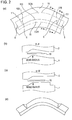
- Fig. 1 includes schematic views illustrating a first embodiment of the present invention.
- this example presents the structure of a first-step die set for manufacturing a member having a V-shaped section by providing a downward bend formation line (bend formation line for downward bend) 110 in a blank 10.
- the first-step die set includes a die 1 and a punch 2, which have sectional shapes corresponding to the V-shaped section of the product.
- Reference numerals 15 and 16 respectively denote a curved edge portion and ends of the curved edge portion.
- SOA and COA are respectively denote observation parts where whether or not wrinkling occurs and where whether or not cracking occurs is observed in the product manufactured from the blank 10 (similarly denoting hereafter).
- FIG. 1 View (d) of Fig. 1 illustrates the shape of a second-step formed product (a metal component with a three-dimensional edge) obtained by further forming a first-step formed product having been obtained with the first-step die set illustrated in views (a), (b), and (c) of Fig. 1 with the second-step die set, which will be described later.
- a second-step formed product a metal component with a three-dimensional edge
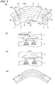
- Fig. 2 includes schematic views illustrating a second embodiment of the present invention.
- this example presents the structure of the first-step die set with which downward bend formation lines 111 and upward bend formation lines 120 (bend formation lines for upward bend) are added to the blank 10 of the first embodiment, so that middle portions 6 and catch portions 5 (corresponding to the ends 16 of the curved edge portion 15 illustrated in Fig. 1 ) are provided.
- elements that are the same as or correspond to those illustrated in the above-described drawing are denoted by the same reference numerals, and description thereof is omitted.
- View (d) of Fig. 2 illustrates the shape of the second-step formed product (metal component with a three-dimensional edge) obtained by further forming the first-step formed product having been obtained with the first-step die set illustrated in views (a), (b), and (c) of Fig. 2 with the second-step die set, which will be described later.
- Fig. 3 includes schematic views illustrating a third embodiment of the present invention.
- this example presents the structure of the first-step die set with which, in order to manufacture a member having an M-shaped section, the downward bend formation lines 111 and 112 and upward bend formation lines 121 and 122 are added in the first embodiment, so that the middle portions 6 and the catch portions 5 are provided.
- elements that are the same as or correspond to those illustrated in the above-described drawings are denoted by the same reference numerals, and description thereof is omitted.
- FIG. 3 illustrates the shape of the second-step formed product (metal component with a three-dimensional edge) obtained by further forming the first-step formed product having been obtained with the first-step die set illustrated in views (a), (b), and (c) of Fig. 3 with the second-step die set, which will be described later.
- Fig. 4 includes schematic views illustrating a forth embodiment of the present invention. As illustrated in views (a), (b), and (c) of Fig. 4 , this example presents the structure of the first-step die set. In this case, a downward bend formation line 113 and an upward bend formation line 123 are respectively provided instead of the downward bend formation line 111 and the upward bend formation line 121 of the third embodiment with the first-step die set.
- the downward bend formation line 113 and the upward bend formation line 123 each have a portion 50 having a lager curvature than those of the other portions.
- elements that are the same as or correspond to those illustrated in the above-described drawings are denoted by the same reference numerals, and description thereof is omitted.
- View (d) of Fig. 4 illustrates the shape of the second-step formed product (metal component with a three-dimensional edge) obtained by further forming the first-step formed product having been obtained with the first-step die set illustrated in views (a), (b), and (c) of Fig. 4 with the second-step die set, which will be described later.
- Fig. 5 includes schematic views illustrating a fifth embodiment of the present invention.
- This example presents the structure of the second-step die set.
- the ends 16 of the curved edge portion 15 of a first-step formed product 11 are held by securing blocks (lower and upper) 21 and 22, and a cam slider 24 and cam driver 25 are provided as a mechanism that presses the securing blocks 21 and 22.
- the ends 16 of the curved edge portion 15 are pressed by contact surfaces of the securing blocks (upper) 22, and accordingly, the distance between one of the ends 16 of the curved edge portion 15 and the opposite end 16 of the curved edge portion 15 is reduced.
- Fig. 6 includes schematic views illustrating a sixth embodiment of the present invention.
- This example presents the structure of the second-step die set in which, as mechanisms that hold the first-step formed product 11, columnar pilot pins 23 are added to the second-step die set of the fifth embodiment.
- Circular holes 30 are formed in the first-step formed product 11 at a stage where the blank for the first-step formed product 11 is manufactured.
- the circular holes 30 allow the pilot pins 23 to be inserted therethrough.
- elements that are the same as or correspond to those illustrated in the above-described drawings are denoted by the same reference numerals, and description thereof is omitted.
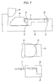
- Fig. 7 includes schematic views illustrating a seventh embodiment of the present invention.
- This example presents the structure of a second-step die set in which, as mechanisms that hold the first-step formed product 11, the ends of the curved edge portion have convex arc shapes and contact surfaces of the securing blocks (upper) 22 have concave arc shapes, so that the ends of the curved edge portion and the contact surfaces of the securing blocks (upper) 22 form arc-shaped contact portions 31 in the fifth embodiment.
- elements that are the same as or correspond to those illustrated in the above-described drawings are denoted by the same reference numerals, and description thereof is omitted.
- Fig. 8 includes schematic views illustrating an eighth embodiment of the present invention.
- This example presents a case in which the second-step die set includes a pressing jig 40 that presses the curved edge portion.
- the curved edge portion is locally processed into the three-dimensional shape when the curved edge portion rises 41 (arrow 41).
- elements that are the same as or correspond to those illustrated in the above-described drawings are denoted by the same reference numerals, and description thereof is omitted.
- the curved edge portion 15 is processed into the three-dimensional shape while being rotated about the downward bend formation line 110 in the arrow 41 direction.
- the curved edge portion 15 collides with the pressing jig 40 when the pressing jig 40 is secured (held) at the position illustrated in the drawing.
- the processing of the curved edge portion 15 into the three-dimensional is further attempted while the curved edge portion 15 is being rotated, the curved edge portion 15 is pressed by the jig 40.
- Fig. 9 includes schematic views illustrating a ninth embodiment of the present invention.
- This example presents a case where the second-step die set includes a pressing block 42 that suppresses excessive rise of a rise 43 at an arc-shaped portion of the downward bend formation line 110 that is processed into the arcuate three-dimensional shape.
- elements that are the same as or correspond to those illustrated in the above-described drawings are denoted by the same reference numerals, and description thereof is omitted.
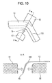
- Fig. 10 includes schematic views illustrating a tenth embodiment of the present invention.
- the second-step die set includes restrike tools (concave and convex) 60 and 61.
- the restrike tools 60 and 61 correct the curved edge portion 15 that is locally processed into the three-dimensional shape of the formed product during or after the second step 12 so that the bend edge portion 15 has a desired shape.
- elements that are the same as or correspond to those illustrated in the above-described drawings are denoted by the same reference numerals, and description thereof is omitted.
- Fig. 11 includes schematic views illustrating an eleventh embodiment of the present invention.
- This example presents the structure of the second-step die set.
- a punch 73 that is brought into contact with a central part of the curved edge portion 15 of the first-step formed product 11 is urged by the cam slider 24 and the cam driver 25, thereby applying a push 80 to the central portion so as to rotate 81 both the ends. This reduces the distance between both the ends.
- a non-curved edge portion which is adjacent to the central portion pressed by the punch 73 with the downward bend formation line 110 interposed therebetween, serves as a holding portion 32.
- the holding portion is held by plate pressing pads (lower and upper) 71 and 72 so that the holding portion can only slide in the horizontal direction.
- the punch 73, the cam slider 24, the cam driver 25, and the plate pressing pads 71 and 72 are supported by a holder 20.
- the metal components with a three-dimensional edge were manufactured.
- the raw material of each of the metal components with a three-dimensional edge was a blank cut from a steel sheet having mechanical characteristics listed in Table 1.
- Forming methods listed in Table 2 were used to manufacture the metal components with a three-dimensional edge. Whether or not cracking occurred and whether or not wrinkling occurred were determined for the obtained components.
- Shape evaluation is determined as follows: the metal components with a three-dimensional edge having shapes not preferably coincident with the target shape are marked with "C”; the metal components with a three-dimensional edge having shapes preferably coincident with the target shape are marked with "B”; and the metal components with a three-dimensional edge having shapes further preferably coincident with the target shape are marked with "A”.
- each of the metal components with a three-dimensional edge was a blank cut from a steel sheet having mechanical characteristics listed in Table 1.
- Forming methods listed in Table 3 (Tables 3-1 to 3-3) were used to manufacture the metal components with a three-dimensional edge. Whether or not wrinkling occurred and whether or not cracking occurred were determined for the obtained components.
- Shape evaluation is determined as follows: the metal components with a three-dimensional edge having shapes equally coincident with the target shape when compared to those of the fifth embodiment are marked with "B"; and the metal components with a three-dimensional edge having shapes more preferably coincident with the target shape than those of the fifth embodiment are marked with "A".
- the bend angles of the downward bend formation lines and the upward bend formation lines of the present invention examples are set to 90 degrees. Furthermore, the bend radius of the bent section in the first step is set to from 0.5 to 30 mm.
- Manufactured components of comparative examples No. 1 to 4 are respectively the same as those of the first to fourth embodiments of the present invention. Whether or not cracking occurs is determined by visually observing the observation part COA illustrated in Figs. 1 to 4 and whether or not wrinkling occurs is determined by visually observing the observation part SOA illustrated in Figs. 1 to 4 . The results are listed in Table 2.
- the metal components with a three-dimensional edge having the shape that is further preferably coincident with the target shape can be manufactured.
- shape evaluation is "A”
- Table 2 No.
Landscapes
- Engineering & Computer Science (AREA)
- Mechanical Engineering (AREA)
- Shaping Metal By Deep-Drawing, Or The Like (AREA)
- Bending Of Plates, Rods, And Pipes (AREA)
Abstract
Description
- The present invention relates to a method for manufacturing a metal component with a three-dimensional edge and die sets for manufacturing the metal component with a three-dimensional edge, and in particular, relates to a method for manufacturing the metal component with a three-dimensional edge and die sets used to manufacture the metal component with a three-dimensional edge for manufacturing the metal component with a three-dimensional edge by press forming in which a curve-shaped edge portion provided in a blank formed of a metal sheet (for example, a high-strength steel sheet having a tensile strength (TS) of 590 MPa or more), or further, the curve-shaped edge portion and part of the blank adjacent to the curve-shaped edge portion are processed into a three-dimensional shape by forming.
- Here, the three-dimensional shape of the three-dimensional edge refers to a three-dimensional shape that is a vertical wall, a chevron shape, or a shape in which one of these shapes is continuous with the other. The blank refers to a single flat-plate raw material to be formed, is cut from an original sheet, and, when cut from the original sheet, has a planar outline shape corresponding to a formed three-dimensional shape.
- As means for obtaining a metal component with a curved edge having a three-dimensional structure, for example, a vertical wall, press forming which is a combination of various types of forming including bending, drawing, and stretch flanging is performed on a single metal sheet in the related art (referred to as the related-art press forming hereafter). As methods of obtaining dimensional accuracy, the following methods have been proposed: a method in which a divergent step is provided in a vertical wall portion (Patent Literature 1); and a method in which a flange portion is formed in two steps (Patent Literature 2). As methods of preventing torsion, the following methods have been proposed: a method in which bending is performed in two steps (Patent Literature 3); and a method of applying stress to a vertical wall portion (Patent Literature 4).
-
- PTL 1: Japanese Unexamined Patent Application Publication No.
2010-5651 - PTL 2: Japanese Unexamined Patent Application Publication No.
2006-289480 - PTL 3: Japanese Unexamined Patent Application Publication No.
2009-241109 - PTL 4: Japanese Unexamined Patent Application Publication No.
2006-305627 - An increase of the strength of steel sheets corresponding to a demand for weight reduction at the same time invites reduction of drawing property, bulging property, and stretch flange formability of steel sheets. In the case where a blank of a high-strength steel sheet is formed so as to manufacture a component with an edge having a three-dimensional structure, for example, a vertical wall, the vertical wall can be formed by bending when the edge portion is straight. However, when formation of the vertical wall is attempted by ordinary press forming (stretch flanging or drawing) in an edge portion having a curved shape, the line length of a boundary curve on a blank edge side is different from that on a bent portion side in an edge region to be processed into the vertical wall. Thus, when stretch flanging is performed, cracking occurs, and when drawing is performed, wrinkling occurs. At this time, by optimizing forming conditions such as blank holding or changing the shape of the component, the occurrences of cracking and wrinkling can be suppressed to some degree. However, with such methods, it can be said that there is a limit in addressing a further increase in strength such as TS of 980 MPa or more for satisfying the demand for weight reduction.
- Furthermore, problems such as an increase in manufacturing steps and reduction in yields arise in any of the methods such as forming in two steps, providing the step in the vertical wall portion, and the applying stress to the vertical wall portion. Furthermore, the cracking and wrinkling of the vertical wall are caused by the difference in the line length between the boundary curve on the blank side and the boundary curve on the bent portion side in the edge region to be processed into the vertical wall. Thus, countermeasure against cracking and wrinkling is not provided.
- That is, particularly in such a case where the blank is formed of a high-strength steel sheet, using related-art die sets for press forming to manufacture a metal component with a three-dimensional edge having a curved edge portion processed into a three-dimensional shape in a simple process causes cracking and wrinkling to occur. Consequently, a target shape of the metal component with a three-dimensional edge cannot be obtained. Thus, there is a problem in that simplifying the manufacturing process and reducing the weight of the product are very difficult to achieve at the same time.
- The inventors studied means for solving the above-described problem and obtained the following finding while being inspired by paper folding art. That is, a three-dimensional shape having a curved ridge in an edge portion of a paper blank can be formed of paper, which is a material not extending or contracting, by a simple method of folding. Since a workpiece is bent with little deformation by drawing, bulging, and stretch flanging, by applying the method of folding to a metal blank, a metal component with a three-dimensional edge without cracks and wrinkles can be manufactured from a high-strength metal blank in a simple forming process. Furthermore, by suppressing processing of the vertical wall and the bend line into three-dimensional shapes, local deformation can be avoided. Thus, it has been understood that a large region can be processed into a desired three-dimensional shape.
- The present invention is made in accordance with the above-described finding, and the gist of the present invention is as follows.
- (1) A method for manufacturing a metal component with a three-dimensional edge manufactures the metal component with a three-dimensional edge from a blank as a raw material. The blank is cut from a metal sheet and has a curve-shaped curved edge portion having both ends. The curved edge portion, or further, the curved edge portion and part of the blank adjacent to the curved edge portion are processed into a three-dimensional shape by forming. The method includes a step of providing a bend formation line and a step of forming the three-dimensional shape. The step of providing the bend formation line serves as a first step and that provides the bend formation line in the curved edge portion so that a bend radius of a section of a bent portion downwardly or upwardly bent along a curve of the curved edge portion is from 0.5 to 30 mm. The step of forming the three-dimensional shape serves as a second step following the first step, and processes the curved edge portion, or further, the curved edge portion and the part of the blank adjacent to the curved edge portion into the three-dimensional shape from the bend formation line as a start point by moving both end portions of the curved edge portion so as to reduce or increase a distance between both the ends.
- (2) In the method for manufacturing the metal component with a three-dimensional edge according to (1), a flat catch portion and a middle portion, which is connected from the catch portion to both ends or an intermediate region of a portion of a main body of the blank where the bend formation line is provided or at least one of a plurality of bend formation lines are provided, are provided.
- (3) In the method for manufacturing the metal component with a three-dimensional edge according to (1) or (2), a plurality of the bend formation lines are provided, the plurality of bend formation lines are curved lines, and a portion of at least one of the plurality of curved lines has a larger curvature than curvatures of curved portions continuous with the portion of the at least one of the plurality of curved lines on both sides.
- (4) In the method for manufacturing the metal component with a three-dimensional edge according to any one of (1) to (3), in the second step, a vertical wall portion that is adjacent to the curved edge portion and that is processed into the three-dimensional shape is pressed.
- (5) In the method for manufacturing the metal component with a three-dimensional edge according to (1) to (4), in the second step, the bend formation line is pressed as the curved edge portion is processed into the three-dimensional shape.
- (6) In the method for manufacturing the metal component with a three-dimensional edge according to (1) to (5), in the second step, a shape of the curved edge portion is corrected while the curved edge portion is being processed into the three-dimensional shape or after the curved edge portion has been processed into the three-dimensional shape.
- (7) Die sets for manufacturing a metal component with a three-dimensional edge are used when manufacturing the metal component with a three-dimensional edge from a blank as a raw material. The blank is cut from a metal sheet and has a curve-shaped curved edge portion having both ends. The metal component with a three-dimensional edge is manufactured by processing the curved edge portion, or further, the curved edge portion and part of the blank adjacent to the curved edge portion into a three-dimensional shape by forming. The die sets include a first-step die set and a second-step die set. The first-step die set is used for a step of providing a bend formation line to provide the bend formation line in the curved edge portion so that a bend radius of a section of a bent portion downwardly or upwardly bent along a curve of the curved edge portion is from 0.5 to 30 mm. The second-step die set used in the step of forming the three-dimensional shape following the step of providing the bend formation line processes the curved edge portion, or further, the curved edge portion and the part of the blank adjacent to the curved edge portion into the three-dimensional shape from the bend formation line as a start point by moving both end portions of the curved edge portion so as to reduce or increase a distance between both the ends.
- (8) In the die sets for manufacturing the metal component with a three-dimensional edge according to (7), the first-step die set provides the blank with a flat catch portion and a middle portion, which is connected from the catch portion to both ends or an intermediate region of a portion of a main body of the blank where the bend formation line is provided or at least one of a plurality of bend formation lines are provided.
- (9) With the die sets for manufacturing the metal component with a three-dimensional edge according to (7) or (8), a plurality of the bend formation lines are provided, the plurality of bend formation lines are curved lines, and a portion of at least one of the plurality of curved lines has a larger curvature than curvatures of curved portions continuous with the portion of the at least one of the plurality of curved lines on both sides.
- According to the present invention, since the workpiece (material) is bent with little deformation due to drawing, bulging, and stretch flanging, the curved edge portion can be processed into a three-dimensional vertical wall or a three-dimensional chevron shape by forming without the occurrences of cracks and wrinkles. Thus, the metal component with a three-dimensional edge can be manufactured even from a single plate of high-strength steel sheets. Furthermore, since formation with little extension or contraction is possible, a curved edge portion having a small radius of curvature R that cannot be processed into the three-dimensional shape by the related-art forming can be processed into the three-dimensional shape by forming.
-
- [
Fig. 1] Fig. 1 includes schematic views illustrating a first embodiment of the present invention. - [
Fig. 2] Fig. 2 includes schematic views illustrating a second embodiment of the present invention. - [
Fig. 3] Fig. 3 includes schematic views illustrating a third embodiment of the present invention. - [
Fig. 4] Fig. 4 includes schematic views illustrating a fourth embodiment of the present invention. - [
Fig. 5] Fig. 5 includes schematic views illustrating a fifth embodiment of the present invention. - [
Fig. 6] Fig. 6 includes schematic views illustrating a sixth embodiment of the present invention. - [
Fig. 7] Fig. 7 includes schematic views illustrating a seventh embodiment of the present invention. - [
Fig. 8] Fig. 8 includes schematic views illustrating an eighth embodiment of the present invention. - [
Fig. 9] Fig. 9 includes schematic views illustrating a ninth embodiment of the present invention. - [
Fig. 10] Fig. 10 includes schematic views illustrating a tenth embodiment of the present invention. - [
Fig. 11] Fig. 11 includes schematic views illustrating an eleventh embodiment of the present invention. Description of Embodiments - The present invention is a method for manufacturing a metal component with a three-dimensional edge and die sets for manufacturing used to manufacture the metal component. The metal component with a three-dimensional edge is formed of a blank as a raw material cut from a metal sheet and having a curve-shaped curved edge portion having both ends. The metal component with a three-dimensional edge is manufactured by processing the curved edge portion, or further, the curved edge portion and part of the blank adjacent to the curved edge portion into a three-dimensional shape by forming.
- The method for manufacturing includes a step of providing a bend formation line as a first step and a step of forming the three-dimensional shape as a second step. In the step of providing a bend formation line, a downward or upward bend formation line is provided along a curve of the curved edge portion in the curved edge portion. In the step of forming the three-dimensional shape performed next to the step of providing the bend formation line, the curved edge portion, or further, the curved edge portion and the part of the blank adjacent to the curved edge portion are processed into the three-dimensional shape from the bend formation line as a start point by moving both end portions of the curved edge portion so as to reduce or increase the distance between both the ends. Here, types of the curved line having both the ends include a bend formation line having both ends.
- The die sets for manufacturing include a first-step die set and a second-step die set. The first-step die set is used for the step of providing the bend formation line, in which the downward or upward bend formation line is provided along the curve of the curved edge portion in the curved edge portion. The second-step die set is used for the step of forming the three-dimensional shape, which is performed next to the step of providing the bend formation line and in which the curved edge portion, or further, the curved edge portion and the part of the blank adjacent to the curved edge portion are processed into the three-dimensional shape from the bend formation line as the start point by moving both the end portions of the curved edge portion so as to reduce or increase the distance between both the ends. Here, types of the curved line having both the ends include a bend formation line having both ends.
- When the bend formation line is provided in the step of providing the bend formation line, both the end portions of the curved edge portion are moved so as to reduce or increase the distance between both the ends in the step of forming the three-dimensional shape, which is performed next to the step of providing the bend formation line. This causes one of both sides of the bend formation line separated by the bend formation line as the border between both the sides to naturally ascend or descend relative to the other because of the difference between the line lengths on both the sides of the bend formation line. This allows and facilitates the processing of the curved edge portion, or further, the curved edge portion and the part of the blank adjacent to the curved edge portion into the three-dimensional shape from the bend formation line as the start point. Without the step of providing the bend formation line, the processing into the three-dimensional shape by the step of forming the three-dimensional shape is very difficult to be performed.
- The first-step die set used for the step of providing the bend formation line may be any one of die sets used for forming such as roll forming, sequential forming, hydraulic forming, rubber forming, crash forming, drawing, and bulging as long as the bend formation line can be provided in the blank. However, by considering positional accuracy of the bend formation line and production efficiency, a die set for pressing having a die shape corresponding to the bend formation line is preferred.
- Furthermore, the bend radius of the sectional shape of the bend formation line is from 0.5 to 30 mm. Since the bending properties of high-strength steel sheet are poorer than that of mild steel, a bent part may crack when the bend radius of the bend formation line is less than 0.5 mm. In contrast, when the bend radius exceeds 30 mm, the bend formation line is unlikely to become the start point of the processing into the three-dimensional shape in the step of forming the three-dimensional shape. In order to increase efficiency in the step of forming the three-dimensional shape and increase efficiency in prevention of cracking in the bent part, the bend radius is preferably from 1 to 10 mm.
- The second-step die set has a structure in which a first-step formed product (formed product having undergone the step of providing the bend formation line) is moved so as to increase or reduce the distance between both the ends of the curved edge portion. This structure has a mechanism that applies forces or a force to both or one of the ends by using a jig, thereby moving the ends or the end inward or outward.
- In the step of forming the three-dimensional shape, both the end portions of the curved edge portion themselves are also processed into three-dimensional shapes as the both the end portions are moved. Thus, there is a problem in that a mechanism that can still apply a force or forces even when both the end portions are processed into the three-dimensional shapes is required. Furthermore, both the end portions of the curved edge portion are rotated about a position that becomes the start point of the processing into the three-dimensional shapes. Thus, application of the force or the forces is required even when both the end portions are rotated. However, there also is a problem in that realizing such a movement of a die set makes the mechanism complex.
- As a solution to the above-described problems, the part or parts where the force or the forces are applied preferably have a curved surface shape or curved surface shapes. By using a mechanism that causes the curved surface shape or the curved surface shapes provided on the die set to press against the end portion or the end portions of the curved edge portion, the position or positions of a contact point or contact points where the first-step formed product and the die set is brought into contact with each other are sequentially changed on the curved surface or the curved surfaces as the end portions are processed into the three-dimensional shape and rotated. This allows the above-described problems to be solved only by a simple movement of the die set, for example, a linear motion. Specifically, it is sufficient that a mechanism, in which a circular hole is provided in the blank or the first-step formed product and this circular hole is pressed by a columnar pin, be provided. As alternative means, an end portion of the blank or the first-step formed product is formed to have an arc shape.
- In order to increase the stability of forming, it is preferable that a mechanism move one or both the end portions while holding both the end portions so that the first-step formed product is not moved out of the die set. When holding, it is preferable that the first-step formed product be held simply by an upper and lower dies or the like so that the first-step formed product is movable while being maintained in the horizontal position. However, when the first-step formed product is moved while simply maintained in the horizontal position, rising of part of the first-step formed product being held during forming is blocked, and consequently, there exists part of the first-step formed product where a desired shape of the metal component with a three-dimensional edge cannot be provided. Thus, it is preferable that the first-step die set has a structure which provides a flat catch portion and a middle portion in the blank. The middle portion is connected from the catch portion to both ends or an intermediate region of a portion of a main body of the blank where a bend formation line is provided or at least one of a plurality of bend formation lines are provided. By causing the middle portion to be in contact with the part where an angle relative to the horizontal direction continuously changes during formation, both the end portions can be easily moved while maintaining the catch portion in the horizontal position.
- Furthermore, it is preferable that a technique by which curved surfaces are formed at contact points of the catch portions where the catch portions are brought into contact with the second-step die set be applied. Furthermore, by setting the diameters of the circular holes provided in the first-step formed product and the diameters of the columnar pins of the second-step die set to be the same, the ends of the curved edge portion and the pins are rotated in the same plane while constantly being kept separated from one another by a fixed distance. Thus, the catch portions can be easily held. This is similarly applicable also to an embodiment in which the end portion of the blank or the first-step formed product has the arc shape.
- The mechanism of the die set that moves both the end portions of the curved edge portion of the first-step formed product may be, as a method of utilizing the vertical movement by converting the direction of the vertical movement, a mechanism utilizing an inclined surface such as a cam mechanism, a link mechanism, or a mechanism utilizing a lever other than the mechanism that directly transmits the vertical movement of sliding of the pressing machine through a jig such as a punch. Furthermore, a cylinder utilizing electrical power, air pressure, or oil pressure may be used other than the drive force of the pressing machine.
- In the step of forming the three-dimensional shape, when deformation of a portion is more easily performed than processing of the first-step formed product into the three-dimensional shape from the bend formation line as the start point, this part is preferentially deformed. In order to prevent defective formation such as buckling of the bend formation line, it is effective that the curved edge portion of the first-step formed product in which cracking and wrinkling may occur is preferentially processed into the three-dimensional shape. For this purpose, it is preferable that, in a region around the curved edge portion that is desired to be preferentially processed into the three-dimensional shape, a plurality of the bend formation lines be provided, the plurality of bend formation lines are curved lines, and a portion of at least one of the plurality of curved lines have a larger curvature than those of curved portions continuous with the portion of the at least one of the plurality of curved lines on both sides. The increase in the curvature of the bend formation line increases the difference between the line lengths on both the sides of the bend formation line which is the border between both the sides relative to movement amounts of both the end portions of the curved edge portion. Thus, the curved edge portion is easily processed into the three-dimensional shape.
- When processing of the curved edge portion into the three-dimensional shape is locally performed, the other part of the curved edge portion may be insufficiently processed into the three-dimensional shape. As a countermeasure against this problem, it is effective to design a second-step die set so as to press a vertical wall portion adjacent to the part of the curved edge portion locally processed into the three-dimensional shape while the curved edge portion is being processed into the three-dimensional shape. By pressing the curved edge portion being processed into the three-dimensional shape, it is unavoidable that part around the pressed part is processed into the three-dimensional shape. Thus, by using the second-step die set with pressing jigs arranged in various required parts, a large region can be processed into a three-dimensional shape.
- Furthermore, by correcting the shape of the curved edge portion while the curved edge portion is being processed into the three-dimensional shape or after the curved edge portion has been processed into the three-dimensional shape by the second-step die set, the curved edge portion can be processed into a desired shape by forming. A correction method may be any one of methods including crash forming, coining, ironing, reshaping by restriking, and so forth as long as the shape can be corrected by the method. More preferably, the curved edge portion is reshaped by restriking with a cam mechanism. In order to perform processing such as crash forming, coining, ironing, or restriking, a jig including a pair of male and female dies used to process a formed product or a jig that used to secure the formed product is necessary. However, the shape around the curved edge portion is likely to be irregularly varied when the curved edge portion is processed into the three-dimensional shape. Thus, there may be a case where the shape of the jig does not match the shape of a finished product until processing of the curved edge portion into the three-dimensional shape is completed and a case where installation of the jig is difficult because of interference of the jig with the formed product. Thus, by moving the jig with a cam mechanism, the jig can be moved to a position where the jig does not interfere with the formed product at time other than time when the shape of the curved edge portion is corrected. Furthermore, by using a restriking jig, the curved edge portion locally processed into the three-dimensional shape or wrinkling can be corrected.
- In the case where the bend formation line and the curved edge portion or the bend formation lines of the first-step formed product are not equally spaced from one another, as the curved edge portion is processed into the three-dimensional shape with the second-step die set, the bend formation line or the bend formation lines attempt to be processed into an arcuate three-dimensional shape or arcuate three-dimensional shapes with the start point or the start points at the top or the tops when the bend formation line or the bend formation lines are seen from a horizontal surface. At this time, when the bend formation line or the bend formation lines are pressed, deformation in the first-step formed product is distributed to other positions. Thus, the bend formation line or the bend formation lines can be prevented from being processed into the arcuate three-dimensional shape or the arcuate three-dimensional shapes. The position or the positions to be pressed are preferably around the top or the tops of the arcuate shape or the arcuate shapes. A pressing method may be any method such as installation of a metal plate or metal plates near the bend formation line or the bend formation lines. When the processing of the bend formation line or the bend formation lines into the three-dimensional shape or the three-dimensional shapes is excessively performed, the bend formation line or the bend formation lines may buckle near the start point or the start points. Thus, this produces an effect that prevents the bend formation line or the bend formation lines from buckling. Furthermore, since the bend formation line or the bend formation lines can be prevented from bucking, portions of the first-step formed product on both the end sides of the curved edge portion can be further smoothly moved. This also allows the curved edge portion to be further effectively processed into the three-dimensional shape.
- The die sets for manufacturing may include the first-step die set and the second-step die set. The first-step die set is used for the step of providing the bend formation line, in which the downward or upward bend formation line is provided along the curve of the curved edge portion in the curved edge portion. The second-step die set is used for the step of forming the three-dimensional shape, which is performed next to the step of providing the bend formation line and in which the curved edge portion, or further, the curved edge portion and the part of the blank adjacent to the curved edge portion are processed into the three-dimensional shape from the bend formation line as the start point by pressing a central portion between both the ends of the curved edge portion so that a movement is performed so as to reduce the distance between both the ends. Here, types of the curved line having both the ends include a bend formation line having both ends.
- When the bend formation line is provided in the step of providing the bend formation line, the central portion of both the ends of the curved edge portion is pressed so that a movement is perform so as to reduce the distance between both the ends in the step of forming the three-dimensional shape, which is performed next to the step of providing the bend formation line. This causes one of both sides of the bend formation line separated by the bend formation line as the border between both the sides to naturally ascend or descend relative to the other because of the difference between the line lengths on both the sides of the bend formation line. This allows and facilitates the processing of the curved edge portion, or further, the curved edge portion and the part of the blank adjacent to the curved edge portion into the three-dimensional shape from the bend formation line as the start point. Without the step of providing the bend formation line, the processing into the three-dimensional shape by the step of forming the three-dimensional shape is very difficult to be performed.
- The second-step die set has a structure in which the central portion between the both the ends of the curved edge portion of the first-step formed product (formed product having undergone the step of providing the bend formation line) is pressed so that the movement is performed so as to reduce the distance between both the ends of the curved edge portion. This structure has a mechanism that causes the curved edge portion to rise while rotating both the ends by applying a force to the central portion with a jig. When it is attempted to cause the curved edge portion to rise by the related-art press forming, the length of the raw material is insufficient at part of the raw material to be brought into contact with the jig. This causes cracks in the stretched flange. In contrast, according to the present invention, both the end portions of the curved edge portion are rotated about the position that becomes the start point of the processing into the three-dimensional shape. This can compensate for lack of length of the raw material. Here, in order to hold the first-step formed product, it is preferable to press a region near the bend formation line, which becomes the start point when processing into the three-dimensional shape.
-
Fig. 1 includes schematic views illustrating a first embodiment of the present invention. As illustrated in views (a), (b), and (c) ofFig. 1 , this example presents the structure of a first-step die set for manufacturing a member having a V-shaped section by providing a downward bend formation line (bend formation line for downward bend) 110 in a blank 10. The first-step die set includes adie 1 and apunch 2, which have sectional shapes corresponding to the V-shaped section of the product.Reference numerals - View (d) of
Fig. 1 illustrates the shape of a second-step formed product (a metal component with a three-dimensional edge) obtained by further forming a first-step formed product having been obtained with the first-step die set illustrated in views (a), (b), and (c) ofFig. 1 with the second-step die set, which will be described later. -
Fig. 2 includes schematic views illustrating a second embodiment of the present invention. As illustrated in views (a), (b), and (c) ofFig. 2 , this example presents the structure of the first-step die set with which downwardbend formation lines 111 and upward bend formation lines 120 (bend formation lines for upward bend) are added to the blank 10 of the first embodiment, so thatmiddle portions 6 and catch portions 5 (corresponding to theends 16 of thecurved edge portion 15 illustrated inFig. 1 ) are provided. Here, elements that are the same as or correspond to those illustrated in the above-described drawing are denoted by the same reference numerals, and description thereof is omitted. - View (d) of
Fig. 2 illustrates the shape of the second-step formed product (metal component with a three-dimensional edge) obtained by further forming the first-step formed product having been obtained with the first-step die set illustrated in views (a), (b), and (c) ofFig. 2 with the second-step die set, which will be described later. -
Fig. 3 includes schematic views illustrating a third embodiment of the present invention. As illustrated in views (a), (b), and (c) ofFig. 3 , this example presents the structure of the first-step die set with which, in order to manufacture a member having an M-shaped section, the downwardbend formation lines bend formation lines middle portions 6 and thecatch portions 5 are provided. Here, elements that are the same as or correspond to those illustrated in the above-described drawings are denoted by the same reference numerals, and description thereof is omitted. - View (d) of
Fig. 3 illustrates the shape of the second-step formed product (metal component with a three-dimensional edge) obtained by further forming the first-step formed product having been obtained with the first-step die set illustrated in views (a), (b), and (c) ofFig. 3 with the second-step die set, which will be described later. -
Fig. 4 includes schematic views illustrating a forth embodiment of the present invention. As illustrated in views (a), (b), and (c) ofFig. 4 , this example presents the structure of the first-step die set. In this case, a downwardbend formation line 113 and an upwardbend formation line 123 are respectively provided instead of the downwardbend formation line 111 and the upwardbend formation line 121 of the third embodiment with the first-step die set. The downwardbend formation line 113 and the upwardbend formation line 123 each have aportion 50 having a lager curvature than those of the other portions. Here, elements that are the same as or correspond to those illustrated in the above-described drawings are denoted by the same reference numerals, and description thereof is omitted. - View (d) of
Fig. 4 illustrates the shape of the second-step formed product (metal component with a three-dimensional edge) obtained by further forming the first-step formed product having been obtained with the first-step die set illustrated in views (a), (b), and (c) ofFig. 4 with the second-step die set, which will be described later. -
Fig. 5 includes schematic views illustrating a fifth embodiment of the present invention. This example presents the structure of the second-step die set. The ends 16 of thecurved edge portion 15 of a first-step formedproduct 11 are held by securing blocks (lower and upper) 21 and 22, and acam slider 24 andcam driver 25 are provided as a mechanism that presses the securing blocks 21 and 22. The ends 16 of thecurved edge portion 15 are pressed by contact surfaces of the securing blocks (upper) 22, and accordingly, the distance between one of theends 16 of thecurved edge portion 15 and theopposite end 16 of thecurved edge portion 15 is reduced. -
Fig. 6 includes schematic views illustrating a sixth embodiment of the present invention. This example presents the structure of the second-step die set in which, as mechanisms that hold the first-step formedproduct 11, columnar pilot pins 23 are added to the second-step die set of the fifth embodiment. Circular holes 30 are formed in the first-step formedproduct 11 at a stage where the blank for the first-step formedproduct 11 is manufactured. Thecircular holes 30 allow the pilot pins 23 to be inserted therethrough. Here, elements that are the same as or correspond to those illustrated in the above-described drawings are denoted by the same reference numerals, and description thereof is omitted. -
Fig. 7 includes schematic views illustrating a seventh embodiment of the present invention. This example presents the structure of a second-step die set in which, as mechanisms that hold the first-step formedproduct 11, the ends of the curved edge portion have convex arc shapes and contact surfaces of the securing blocks (upper) 22 have concave arc shapes, so that the ends of the curved edge portion and the contact surfaces of the securing blocks (upper) 22 form arc-shapedcontact portions 31 in the fifth embodiment. Here, elements that are the same as or correspond to those illustrated in the above-described drawings are denoted by the same reference numerals, and description thereof is omitted. -
Fig. 8 includes schematic views illustrating an eighth embodiment of the present invention. This example presents a case in which the second-step die set includes apressing jig 40 that presses the curved edge portion. The curved edge portion is locally processed into the three-dimensional shape when the curved edge portion rises 41 (arrow 41). Here, elements that are the same as or correspond to those illustrated in the above-described drawings are denoted by the same reference numerals, and description thereof is omitted. - Here, when seen in section A-A' in
Fig. 8 , thecurved edge portion 15 is processed into the three-dimensional shape while being rotated about the downwardbend formation line 110 in thearrow 41 direction. At this time, thecurved edge portion 15 collides with thepressing jig 40 when thepressing jig 40 is secured (held) at the position illustrated in the drawing. Thus, even when the processing of thecurved edge portion 15 into the three-dimensional is further attempted while thecurved edge portion 15 is being rotated, thecurved edge portion 15 is pressed by thejig 40. -
Fig. 9 includes schematic views illustrating a ninth embodiment of the present invention. This example presents a case where the second-step die set includes apressing block 42 that suppresses excessive rise of arise 43 at an arc-shaped portion of the downwardbend formation line 110 that is processed into the arcuate three-dimensional shape. Here, elements that are the same as or correspond to those illustrated in the above-described drawings are denoted by the same reference numerals, and description thereof is omitted. -
Fig. 10 includes schematic views illustrating a tenth embodiment of the present invention. This example presents a case where the second-step die set includes restrike tools (concave and convex) 60 and 61. Therestrike tools curved edge portion 15 that is locally processed into the three-dimensional shape of the formed product during or after thesecond step 12 so that thebend edge portion 15 has a desired shape. Here, elements that are the same as or correspond to those illustrated in the above-described drawings are denoted by the same reference numerals, and description thereof is omitted. -
Fig. 11 includes schematic views illustrating an eleventh embodiment of the present invention. This example presents the structure of the second-step die set. In this example, apunch 73 that is brought into contact with a central part of thecurved edge portion 15 of the first-step formedproduct 11 is urged by thecam slider 24 and thecam driver 25, thereby applying apush 80 to the central portion so as to rotate 81 both the ends. This reduces the distance between both the ends. Furthermore, in order to restrain a problematic vertical movement of the first-step formedproduct 11, a non-curved edge portion, which is adjacent to the central portion pressed by thepunch 73 with the downwardbend formation line 110 interposed therebetween, serves as a holdingportion 32. The holding portion is held by plate pressing pads (lower and upper) 71 and 72 so that the holding portion can only slide in the horizontal direction. Thepunch 73, thecam slider 24, thecam driver 25, and theplate pressing pads holder 20. - In order to check the effects of the bend radius of the bent section in the first step, the metal components with a three-dimensional edge were manufactured. The raw material of each of the metal components with a three-dimensional edge was a blank cut from a steel sheet having mechanical characteristics listed in Table 1. Forming methods listed in Table 2 were used to manufacture the metal components with a three-dimensional edge. Whether or not cracking occurred and whether or not wrinkling occurred were determined for the obtained components.
- Furthermore, coincidence with a target shape was visually observed. Shape evaluation is determined as follows: the metal components with a three-dimensional edge having shapes not preferably coincident with the target shape are marked with "C"; the metal components with a three-dimensional edge having shapes preferably coincident with the target shape are marked with "B"; and the metal components with a three-dimensional edge having shapes further preferably coincident with the target shape are marked with "A".
- As a result, as listed in Table 2, it has been confirmed that preferable results can be obtained when the bend radius of the bent section in the first step is from 0.5 to 30 mm.
- Next, the metal components with a three-dimensional edge were manufactured. The raw material of each of the metal components with a three-dimensional edge was a blank cut from a steel sheet having mechanical characteristics listed in Table 1. Forming methods listed in Table 3 (Tables 3-1 to 3-3) were used to manufacture the metal components with a three-dimensional edge. Whether or not wrinkling occurred and whether or not cracking occurred were determined for the obtained components.
- Furthermore, coincidence with a target shape was visually observed. Shape evaluation is determined as follows: the metal components with a three-dimensional edge having shapes equally coincident with the target shape when compared to those of the fifth embodiment are marked with "B"; and the metal components with a three-dimensional edge having shapes more preferably coincident with the target shape than those of the fifth embodiment are marked with "A".
- Here, the bend angles of the downward bend formation lines and the upward bend formation lines of the present invention examples are set to 90 degrees. Furthermore, the bend radius of the bent section in the first step is set to from 0.5 to 30 mm. Manufactured components of comparative examples No. 1 to 4 are respectively the same as those of the first to fourth embodiments of the present invention. Whether or not cracking occurs is determined by visually observing the observation part COA illustrated in
Figs. 1 to 4 and whether or not wrinkling occurs is determined by visually observing the observation part SOA illustrated inFigs. 1 to 4 . The results are listed in Table 2. - According to Table 2, when a metal component with a three-dimensional edge is manufactured by processing a curved edge portion of the blank formed of a high-strength steel sheet into a three-dimensional shape by forming, cracking and wrinkling occur in the related-art press forming. In contrast, a desired component can be manufactured without the occurrences of cracking and wrinkling according to the present invention.
- Furthermore, together with the eighth and ninth embodiments, the metal components with a three-dimensional edge having the shape that is further preferably coincident with the target shape (shape evaluation is "A") can be manufactured.
[Table 1] Sheet thickness (mm) YS (MPa) TS (MPa) EI (%) 2.3 810 1190 13 [Table 2] No. Forming method Success/failure in forming Remarks First step Second step Method Bend radius a First embodiment 0.4 Not performed C Cracking in first step Comparative example b First embodiment 0.5 Fifth embodiment B No wrinkling/No cracking Present invention example c First embodiment 1 Fifth embodiment A No wrinkling/No cracking Present invention example d First embodiment 10 Fifth embodiment A No wrinkling/No cracking Present invention example e First embodiment 30 Fifth embodiment B No wrinkling/No cracking Present invention example f First embodiment 35 Fifth embodiment C Wrinkling in second step Comparative example [Table 3-1] No. Forming method Success/failure in forming Shape evaluation Remarks First step Second step Assisting jig 1 Related-art press forming (shape: first embodiment) C Cracking and wrinkling occurred C Comparative example 2 Related-art press forming (shape: second embodiment) C Cracking and wrinkling occurred C Comparative example 3 Related-art press forming (shape: third embodiment) C Cracking and wrinkling occurred C Comparative example 4 Related-art press forming (shape: fourth embodiment) C Cracking and wrinkling occurred C Comparative example 5 First embodiment Fifth embodiment Non B No cracking/No wrinkling B Present invention example 6 First embodiment Fifth embodiment Eighth embodiment B No cracking/No wrinkling A Present invention example 7 First embodiment Fifth embodiment Ninth embodiment B No cracking/No wrinkling A Present invention example B First embodiment Fifth embodiment Tenth embodiment B No cracking/No wrinkling A Present invention example 9 First embodiment Fifth embodiment Eighth and ninth embodiments B No cracking/No wrinkling A Present invention example 10 First embodiment Fifth embodiment Eighth and tenth embodiments B No cracking/No wrinkling A Present invention example 11 First embodiment Fifth embodiment Ninth and tenth embodiments B No cracking/No wrinkling A Present invention example 12 First embodiment Fith embodiment Eighth, ninth, and tenth embodiments B No cracking/No wrinkling A Present invention example 13 First embodiment Sixth embodiment Non B No cracking/No wrinkling B Present invention example 14 First embodiment Sixth embodiment Eighth embodiment B No cracking/No wrinkling A Present invention example 15 First embodiment Sixth embodiment Ninth embodiment B No cracking/No wrinkling A Present invention example 16 First embodiment Sixth embodiment Tenth embodiment B No cracking/No wrinkling A Present invention example 17 First embodiment Sixth embodiment Eighth and ninth embodiments B No cracking/No wrinkling A Present invention example 18 First embodiment Sixth embodiment Eighth and tenth embodiments B No cracking/No wrinkling A Present invention example 19 First embodiment Sixth embodiment Ninth and tenth embodiments B No cracking/No wrinkling A Present invention example 20 First embodiment Sixth embodiment Eighth, ninth, and tenth embodiments B No cracking/No wrinkling A Present invention example 21 First embodiment Seventh embodiment Non B No cracking/No wrinkling B Present invention example 22 First embodiment Seventh embodiment Eighth embodiment B No cracking/No wrinkling A Present invention example 23 First embodiment Seventh embodiment Ninth embodiment B No cracking/No wrinkling A Present invention example 24 First embodiment Seventh embodiment Tenth embodiment B No cracking/No wrinkling A Present invention example 25 First embodiment Seventh embodiment Eighth and ninth embodiments B No cracking/No wrinkling A Present invention example 26 First embodiment Seventh embodiment Eighth and tenth embodiments B No cracking/No wrinkling A Present invention example 27 First embodiment Seventh embodiment Ninth and tenth embodiments B No cracking/No wrinkling A Present invention example 28 First embodiment Seventh embodiment Eighth, ninth, and tenth embodiments B No cracking/No wrinkling A Present invention example 29 Second embodiment Fifth embodiment Non B No cracking/No wrinkling B Present invention example 30 Second embodiment Fifth embodiment Eighth embodiment B No cracking/No wrinkling A Present invention example 31 Second embodiment Fifth embodiment Ninth embodiment B No cracking/No wrinkling A Present invention example 33 Second embodiment Fifth embodiment Tenth embodiment B No cracking/No wrinkling A Present invention example 34 Second embodiment Fifth embodiment Eighth and ninth embodiments B No cracking/No wrinkling A Present invention example 35 Second embodiment Fifth embodiment Eighth end tenth embodiments B No cracking/No wrinkling A Present invention example 36 Second embodiment Fifth embodiment Ninth and tenth embodiments B No cracking/No wrinkling A Present invention example 37 Second embodiment Fifth embodiment Eighth, ninth, and tenth embodiments B No cracking/No wrinkling A Present invention example 32 Second embodiment Sixth embodiment Non B No cracking/No wrinkling B Present invention example 38 Second embodiment Sixth embodiment Eighth embodiment B No cracking/No wrinkling A Present invention example 39 Second embodiment Sixth embodiment Ninth embodiment B No cracking/No wrinkling A Present invention example 40 Second embodiment Sixth embodiment Tenth embodiment B No cracking/No wrinkling A Present invention example 41 Second embodiment Sixth embodiment Eighth and ninth embodiments B No cracking/No wrinkling A Present invention example 42 Second embodiment Sixth embodiment Eighth and tenth embodiments B No cracking/No wrinkling A Present invention example 43 Second embodiment Sixth embodiment Ninth and tenth embodiments B No cracking/No wrinkling A Present invention example 44 Second embodiment Seventh embodiment Eighth, ninth, and tenth embodiments B No cracking/No wrinkling A Present invention example 45 Second embodiment Seventh embodiment Non B No cracking/No wrinkling B Present invention example 46 Second embodiment Seventh embodiment Eighth embodiment B No cracking/No wrinkling A Present invention example 47 Second embodiment Seventh embodiment Ninth embodiment B No cracking/No wrinkling A Present invention example 48 Second embodiment Seventh embodiment Tenth embodiment B No cracking/No wrinkling A Present invention example 49 Second embodiment Seventh embodiment Eighth and ninth embodiments B No cracking/No wrinkling A Present invention example 50 Second embodiment Seventh embodiment Eighth and tenth embodiments B No cracking/No wrinkling A Present invention example [Table 3-2] No. Forming method Success/failure in forming Shape Evaluation Remarks First step Second step Assisting jig 51 Second embodiment Seventh embodiment Ninth and tenth embodiments B No cracking/No wrinkling A Present invention example 52 Second embodiment Seventh embodiment Eighth, Ninth, and tenth embodiments B No cracking/No wrinkling A Present invention example 53 Third embodiment Fifth embodiment Non B No cracking/No wrinkling B Present invention example 54 Third embodiment Fifth embodiment Eighth embodiment B No cracking/No wrinkling A Present invention example 55 Third embodiment Fifth embodiment Ninth embodiment B No cracking/No wrinkling A Present invention example 56 Third embodiment Fifth embodiment Tenth embodiment B No cracking/No wrinkling A Present invention example 57 Third embodiment Fifth embodiment Eighth and ninth embodiments B No cracking/No wrinkling A Present invention example 58 Third embodiment Fifth embodiment Eighth and tenth embodiments B No cracking/No wrinkling A Present invention example 59 Third embodiment Fifth embodiment Ninth and tenth embodiments B No cracking/No wrinkling A Present invention example 60 Third embodiment Fifth embodiment Eighth, Ninth, and tenth embodiments B No cracking/No wrinkling A Present invention example 61 Third embodiment Sixth embodiment Non B No cracking/No wrinkling B Present invention example 62 Third embodiment Sixth embodiment Eighth embodiment B No cracking/No wrinkling A Present invention example 63 Third embodiment Sixth embodiment Ninth embodiment B No cracking/No wrinkling A Present invention example 64 Third embodiment Sixth embodiment Tenth embodiment B No cracking/No wrinkling A Present invention example 65 Third embodiment Sixth embodiment Eighth and ninth embodiments B No cracking/No wrinkling A Present invention example 66 Third embodiment Sixth embodiment Eighth and tenth embodiments B No cracking/No wrinkling A Present invention example 67 Third embodiment Sixth embodiment Ninth and tenth embodiments B No cracking/No wrinkling A Present invention example 68 Third embodiment Sixth embodiment Eighth, Ninth, and tenth embodiments B No cracking/No wrinkling A Present invention example 69 Third embodiment Seventh embodiment Non B No cracking/No wrinkling B Present invention example 70 Third embodiment Seventh embodiment Eighth embodiment B No cracking/No wrinkling A Present invention example 71 Third embodiment Seventh embodiment Ninth embodiment B No cracking/No wrinkling A Present invention example 72 Third embodiment Seventh embodiment Tenth embodiment B No cracking/No wrinkling A Present invention example 73 Third embodiment Seventh embodiment Eighth and ninth embodiments B No cracking/No wrinkling A Present invention example 74 Third embodiment Seventh embodiment Eighth and tenth embodiments B No cracking/No wrinkling A Present invention example 75 Third embodiment Seventh embodiment Ninth and tenth embodiments B No cracking/No wrinkling A Present invention example 76 Third embodiment Seventh embodiment Eighth, Ninth, and tenth embodiments B No cracking/No wrinkling A Present invention example 77 Fourth embodiment Fifth embodiment Non B No cracking/No wrinkling B Present invention example 78 Fourth embodiment Fifth embodiment Eighth embodiment B No cracking/No wrinkling A Present invention example 79 Fourth embodiment Fifth embodiment Ninth embodiment B No cracking/No wrinkling A Present invention example 80 Fourth embodiment Fifth embodiment Tenth embodiment B No cracking/No wrinkling A Present invention example 81 Fourth embodiment Fifth embodiment Eighth and ninth embodiments B No cracking/No wrinkling A Present invention example 82 Fourth embodiment Fifth embodiment Eighth and tenth embodiments B No cracking/No wrinkling A Present invention example 83 Fourth embodiment Fifth embodiment Ninth and tenth embodiments B No cracking/No wrinkling A Present invention example 84 Fourth embodiment Fifth embodiment Eighth, Ninth, and tenth embodiments B No cracking/No wrinkling A Present invention example 85 Fourth embodiment Sixth embodiment Non B No cracking/No wrinkling B Present invention example 86 Fourth embodiment Sixth embodiment Eighth embodiment B No cracking/No wrinkling A Present invention example 87 Fourth embodiment Sixth embodiment Ninth embodiment B No cracking/No wrinkling A Present invention example 88 Fourth embodiment Sixth embodiment Tenth embodiment B No cracking/No wrinkling A Present invention example 89 Fourth embodiment Sixth embodiment Eighth and ninth embodiments B No cracking/No wrinkling A Present invention example 90 Fourth embodiment Sixth embodiment Eighth and tenth embodiments B No cracking/No wrinkling A Present invention example 91 Fourth embodiment Sixth embodiment Ninth and tenth embodiments B No cracking/No wrinkling A Present invention example 92 Fourth embodiment Sixth embodiment Eighth, Ninth, and tenth embodiments B No cracking/No wrinkling A Present invention example 93 Fourth embodiment Seventh embodiment Non B No cracking/No wrinkling B Present invention example 94 Fourth embodiment Seventh embodiment Eighth embodiment B No cracking/No wrinkling A Present invention example 95 Fourth embodiment Seventh embodiment Ninth embodiment B No cracking/No wrinkling A Present invention example 96 Fourth embodiment Seventh embodiment Tenth embodiment B No cracking/No wrinkling A Present invention example 97 Fourth embodiment Seventh embodiment Eighth and ninth embodiments B No cracking/No wrinkling A Present invention example 98 Fourth embodiment Seventh embodiment Eighth and tenth embodiments B No cracking/No wrinkling A Present invention example 99 Fourth embodiment Seventh embodiment Ninth and tenth embodiments B No cracking/No wrinkling A Present invention example 100 Fourth embodiment Seventh embodiment Eighth, Ninth, and tenth embodiments B No cracking/No wrinkling A Present invention example [Table 3-3] Forming method Success/failure in forming Shape Evaluation Remarks No. First step Second step Assisting jig 51 First embodiment Eleventh embodiment Non B No cracking/No wrinkling B Present invention example 52 First embodiment Eleventh embodiment Eighth embodiment B No cracking/No wrinkling A Present invention example 53 First embodiment Eleventh embodiment Ninth embodiment B No cracking/No wrinkling A Present invention example 54 First embodiment Eleventh embodiment Eighth and ninth embodiments B No cracking/No wrinkling A Present invention example 55 Second embodiment Eleventh embodiment Non B No cracking/No wrinkling B Present invention example 56 Second embodiment Eleventh embodiment Eighth embodiment B No cracking/No wrinkling A Present invention example 57 Second embodiment Eleventh embodiment Ninth embodiment B No cracking/No wrinkling A Present invention example 58 Second embodiment Eleventh embodiment Eighth and ninth embodiments B No cracking/No wrinkling A Present invention example 59 Third embodiment Eleventh embodiment Non B No cracking/No wrinkling B Present invention example 60 Third embodiment Eleventh embodiment Eighth embodiment B No cracking/No wrinkling A Present invention example 61 Third embodiment Eleventh embodiment Ninth embodiment B No cracking/No wrinkling A Present invention example 62 Third embodiment Eleventh embodiment Eighth and ninth embodiments B No cracking/No wrinkling A Present invention example 63 Fourth embodiment Eleventh embodiment Non B No cracking/No wrinkling B Present invention example 64 Fourth embodiment Eleventh embodiment Eighth embodiment B No cracking/No wrinkling A Present invention example 65 Fourth embodiment Eleventh embodiment Ninth embodiment B No cracking/No wrinkling A Present invention example 66 Fourth embodiment Eleventh embodiment Eighth and ninth embodiments B No cracking/No wrinkling A Present invention example -
- 1
- die
- 2
- punch
- 5
- catch portion
- 6
- middle portion
- 10
- blank
- 11
- first-step formed product
- 12
- formed product during or after second step
- 15
- curved edge portion
- 16
- end of curved edge portion
- 20
- holder
- 21
- securing block (lower)
- 22
- securing block (upper)
- 23
- pilot pin
- 24
- cam slider
- 25
- cam driver
- 30
- circular hole
- 31
- arc-shaped contact portion
- 32
- holding portion
- 40
- pressing jig
- 41
- rise of curved edge portion
- 42
- pressing block
- 43
- rise at arc-shaped portion
- 50
- portion having lager curvature
- 60
- restrike tool (concave)
- 61
- restrike tool (convex)
- 71
- plate pressing pad (lower)
- 72
- plate pressing pad (upper)
- 73
- punch
- 80
- push
- 81
- rotate
- 110, 111, 112, 113
- downward bend
- 120, 121, 122, 123
- upward bend
Claims (9)
- A method for manufacturing a metal component with a three-dimensional edge, the method being for manufacturing the metal component with a three-dimensional edge from a blank as a raw material, the blank being cut from a metal sheet and having a curve-shaped curved edge portion having both ends, the metal component with a three-dimensional edge being manufactured by processing the curved edge portion, or further, the curved edge portion and part of the blank adjacent to the curved edge portion into a three-dimensional shape by forming, the method comprising:a step of providing a bend formation line that serves as a first step and that provides the bend formation line in the curved edge portion so that a bend radius of a section of a bent portion downwardly or upwardly bent along a curve of the curved edge portion is from 0.5 to 30 mm; anda step of forming the three-dimensional shape that serves as a second step following the first step, and that processes the curved edge portion, or further, the curved edge portion and the part of the blank adjacent to the curved edge portion into the three-dimensional shape from the bend formation line as a start point by moving both end portions of the curved edge portion so as to reduce or increase a distance between both the ends.
- The method for manufacturing the metal component with a three-dimensional edge according to Claim 1,
wherein, in the first step, a flat catch portion and a middle portion, which is connected from the catch portion to both ends or an intermediate region of a portion of a main body of the blank where the bend formation line is provided or at least one of a plurality of bend formation lines are provided, are provided. - The method for manufacturing the metal component with a three-dimensional edge according to Claim 1 or 2,
wherein a plurality of the bend formation lines are provided, the plurality of bend formation lines are curved lines, and a portion of at least one of the plurality of curved lines has a larger curvature than curvatures of curved portions continuous with the portion of the at least one of the plurality of curved lines on both sides. - The method for manufacturing the metal component with a three-dimensional edge according to any one of Claims 1 to 3,
wherein, in the second step, a vertical wall portion that is adjacent to the curved edge portion and that is processed into the three-dimensional shape is pressed. - The method for manufacturing the metal component with a three-dimensional edge according to any one of Claims 1 to 4,
wherein, in the second step, the bend formation line is pressed as the curved edge portion is processed into the three-dimensional shape. - The method for manufacturing the metal component with a three-dimensional edge according to any one of Claims 1 to 5,
wherein, in the second step, a shape of the curved edge portion is corrected while the curved edge portion is being processed into the three-dimensional shape or after the curved edge portion has been processed into the three-dimensional shape. - Die sets for manufacturing a metal component with a three-dimensional edge, the die sets used when manufacturing the metal component with a three-dimensional edge from a blank as a raw material, the blank being cut from a metal sheet and having a curve-shaped curved edge portion having both ends, the metal component with a three-dimensional edge being manufactured by processing the curved edge portion, or further, the curved edge portion and part of the blank adjacent to the curved edge portion into a three-dimensional shape by forming, the die sets comprising:a first-step die set used for a step of providing a bend formation line to provide the bend formation line in the curved edge portion so that a bend radius of a section of a bent portion downwardly or upwardly bent along a curve of the curved edge portion is from 0.5 to 30 mm; anda second-step die set used in a step of forming the three-dimensional shape following the step of providing the bend formation line to process the curved edge portion, or further, the curved edge portion and the part of the blank adjacent to the curved edge portion into the three-dimensional shape from the bend formation line as a start point by moving both end portions of the curved edge portion so as to reduce or increase a distance between both the ends.
- The die sets for manufacturing the metal component with a three-dimensional edge according to Claim 7,
wherein the first-step die set provides the blank with a flat catch portion and a middle portion, which is connected from the catch portion to both ends or an intermediate region of a portion of a main body of the blank where the bend formation line is provided or at least one of a plurality of bend formation lines are provided. - The die sets for manufacturing the metal component with a three-dimensional edge according to Claim 7 or 8,
wherein a plurality of the bend formation lines are provided, the plurality of bend formation lines are curved lines, and a portion of at least one of the plurality of curved lines has a larger curvature than curvatures of curved portions continuous with the portion of the at least one of the plurality of curved lines on both sides.
Applications Claiming Priority (3)
| Application Number | Priority Date | Filing Date | Title |
|---|---|---|---|
| JP2013008002A JP6022364B2 (en) | 2013-01-21 | 2013-01-21 | Mold for manufacturing metal parts with solid edges |
| JP2013008001A JP6022363B2 (en) | 2013-01-21 | 2013-01-21 | Mold for manufacturing metal parts with solid edges |
| PCT/JP2014/000241 WO2014112391A1 (en) | 2013-01-21 | 2014-01-20 | Method for manufacturing metal component with three-dimensional edge, and die for manufacturing |
Publications (3)
| Publication Number | Publication Date |
|---|---|
| EP2946849A1 true EP2946849A1 (en) | 2015-11-25 |
| EP2946849A4 EP2946849A4 (en) | 2015-12-30 |
| EP2946849B1 EP2946849B1 (en) | 2018-03-14 |
Family
ID=51209485
Family Applications (1)
| Application Number | Title | Priority Date | Filing Date |
|---|---|---|---|
| EP14740576.5A Not-in-force EP2946849B1 (en) | 2013-01-21 | 2014-01-20 | Method for manufacturing metal component with three-dimensional edge and die sets for manufacturing the same |
Country Status (5)
| Country | Link |
|---|---|
| US (2) | US10029293B2 (en) |
| EP (1) | EP2946849B1 (en) |
| KR (1) | KR101708581B1 (en) |
| CN (1) | CN104936717B (en) |
| WO (1) | WO2014112391A1 (en) |
Cited By (1)
| Publication number | Priority date | Publication date | Assignee | Title |
|---|---|---|---|---|
| KR20200141513A (en) * | 2018-05-24 | 2020-12-18 | 제이에프이 스틸 가부시키가이샤 | Manufacturing method of press parts |
Families Citing this family (6)
| Publication number | Priority date | Publication date | Assignee | Title |
|---|---|---|---|---|
| RU2693402C1 (en) * | 2016-03-28 | 2019-07-02 | Ниппон Стил Энд Сумитомо Метал Корпорейшн | Method of making pressed article |
| CN108240505B (en) * | 2016-12-26 | 2019-12-13 | 浙江三花汽车零部件有限公司 | A water valve and its mounting bracket |
| CN110366651B (en) * | 2017-03-30 | 2022-08-19 | 株式会社爱信 | Method for manufacturing casing of starting device |
| KR102955291B1 (en) * | 2021-01-05 | 2026-04-21 | 에스케이온 주식회사 | Manufacturing Method for Secondary Battery Pouch, Manufacturing Apparatus and Secondary Battery Thereof |
| CA3253940A1 (en) | 2022-06-30 | 2024-01-04 | Cleveland-Cliffs Steel Properties Inc. | Method for prevention of premature edge fracture at draw bead |
| CN117282804A (en) * | 2023-09-07 | 2023-12-26 | 上海新时达电气股份有限公司 | A pipe rebound compensation method, device, electronic equipment and storage medium |
Family Cites Families (10)
| Publication number | Priority date | Publication date | Assignee | Title |
|---|---|---|---|---|
| JPS5645219A (en) * | 1979-09-20 | 1981-04-24 | Toshiba Corp | Forming method for three dimensionally curved sheet |
| DE3939356A1 (en) | 1989-11-24 | 1991-05-29 | Mannesmann Ag | MECHANICAL TUBE EXPANDER |
| JP2762634B2 (en) * | 1989-11-30 | 1998-06-04 | トヨタ自動車株式会社 | Press working method |
| JP2006305627A (en) * | 2005-03-28 | 2006-11-09 | Kobe Steel Ltd | Method for forming curve-shaped channel member |
| JP4693475B2 (en) | 2005-04-14 | 2011-06-01 | アイダエンジニアリング株式会社 | Press molding method and mold used therefor |
| GB2444574B (en) * | 2007-06-13 | 2008-11-12 | Gregory Epps | Bending sheet material |
| JP2009241109A (en) * | 2008-03-31 | 2009-10-22 | Kobe Steel Ltd | Bend-forming method of channel member |
| JP5079604B2 (en) * | 2008-06-26 | 2012-11-21 | 新日本製鐵株式会社 | Metal mold for press forming of cross-section hat-shaped member and press molding method |
| JP2010227995A (en) * | 2009-03-30 | 2010-10-14 | Kobe Steel Ltd | Method of forming curved channel member |
| JP4858624B2 (en) * | 2009-04-01 | 2012-01-18 | Jfeスチール株式会社 | Torsion beam manufacturing method and torsion beam |
-
2014
- 2014-01-20 WO PCT/JP2014/000241 patent/WO2014112391A1/en not_active Ceased
- 2014-01-20 EP EP14740576.5A patent/EP2946849B1/en not_active Not-in-force
- 2014-01-20 KR KR1020157017873A patent/KR101708581B1/en not_active Expired - Fee Related
- 2014-01-20 US US14/762,372 patent/US10029293B2/en active Active
- 2014-01-20 CN CN201480005381.0A patent/CN104936717B/en active Active
-
2018
- 2018-06-07 US US16/002,267 patent/US10500625B2/en not_active Expired - Fee Related
Cited By (3)
| Publication number | Priority date | Publication date | Assignee | Title |
|---|---|---|---|---|
| KR20200141513A (en) * | 2018-05-24 | 2020-12-18 | 제이에프이 스틸 가부시키가이샤 | Manufacturing method of press parts |
| EP3804875A4 (en) * | 2018-05-24 | 2021-08-04 | JFE Steel Corporation | PRESS FORMED COMPONENT MANUFACTURING PROCESS |
| US11731185B2 (en) | 2018-05-24 | 2023-08-22 | Jfe Steel Corporation | Method for manufacturing pressed component |
Also Published As
| Publication number | Publication date |
|---|---|
| EP2946849B1 (en) | 2018-03-14 |
| US10029293B2 (en) | 2018-07-24 |
| KR20150093207A (en) | 2015-08-17 |
| US20150360272A1 (en) | 2015-12-17 |
| CN104936717A (en) | 2015-09-23 |
| US20180281043A1 (en) | 2018-10-04 |
| US10500625B2 (en) | 2019-12-10 |
| WO2014112391A1 (en) | 2014-07-24 |
| KR101708581B1 (en) | 2017-02-20 |
| CN104936717B (en) | 2016-11-30 |
| EP2946849A4 (en) | 2015-12-30 |
Similar Documents
| Publication | Publication Date | Title |
|---|---|---|
| US10500625B2 (en) | Method for manufacturing metal component with three-dimensional edge and die sets for manufacturing the same | |
| RU2535414C2 (en) | Method of forming l-shape component (versions) | |
| EP3476500B1 (en) | Method and device for manufacturing pressed component | |
| EP2896467B1 (en) | Method for producing curved article | |
| JP6128226B2 (en) | PRESS-MOLDED PRODUCT, PRESS-MOLDED PRODUCTION METHOD, AND PRESS-MOLDED PRODUCTION DEVICE | |
| US11059085B2 (en) | Manufacturing method and manufacturing apparatus for press-formed article | |
| JP6146480B2 (en) | Steel plate material manufacturing method and manufacturing apparatus | |
| JP6672932B2 (en) | Method and apparatus for manufacturing pressed part having hat cross section | |
| US10933457B2 (en) | Pressing machine and a method for manufacturing a press-formed product | |
| CN111727089B (en) | Method for manufacturing press-molded member, press-molding device, and metal plate for press-molding | |
| EP2878392A1 (en) | Press-forming mold and method for manufacturing press-formed product | |
| EP3842164A1 (en) | Press-molding method | |
| KR20170063845A (en) | Method for producing press-molded article, production apparatus, and production line | |
| JP4693475B2 (en) | Press molding method and mold used therefor | |
| EP3127625B1 (en) | Method and apparatus for forming steel pipe using three-point bending-press forming | |
| EP3064288B1 (en) | Method for forming an l-shaped part | |
| CN110709181A (en) | Manufacturing method of press-molded product and press production line | |
| JP2008030090A (en) | Bending correction method for shape steel and straightening apparatus for shape steel | |
| EP3895824B1 (en) | Press forming method | |
| JP5593191B2 (en) | Metal pipe manufacturing equipment | |
| EP4556134A1 (en) | Method for manufacturing press-molded article | |
| JP7564448B2 (en) | Manufacturing method and manufacturing equipment for press-molded products | |
| CN117295565A (en) | Stamping forming method | |
| JP6022363B2 (en) | Mold for manufacturing metal parts with solid edges | |
| JP7861896B1 (en) | Manufacturing method for press-formed products |
Legal Events
| Date | Code | Title | Description |
|---|---|---|---|
| PUAI | Public reference made under article 153(3) epc to a published international application that has entered the european phase |
Free format text: ORIGINAL CODE: 0009012 |
|
| 17P | Request for examination filed |
Effective date: 20150622 |
|
| AK | Designated contracting states |
Kind code of ref document: A1 Designated state(s): AL AT BE BG CH CY CZ DE DK EE ES FI FR GB GR HR HU IE IS IT LI LT LU LV MC MK MT NL NO PL PT RO RS SE SI SK SM TR |
|
| AX | Request for extension of the european patent |
Extension state: BA ME |
|
| A4 | Supplementary search report drawn up and despatched |
Effective date: 20151202 |
|
| RIC1 | Information provided on ipc code assigned before grant |
Ipc: B21D 22/26 20060101AFI20151126BHEP Ipc: B21D 5/01 20060101ALI20151126BHEP |
|
| DAX | Request for extension of the european patent (deleted) | ||
| GRAP | Despatch of communication of intention to grant a patent |
Free format text: ORIGINAL CODE: EPIDOSNIGR1 |
|
| STAA | Information on the status of an ep patent application or granted ep patent |
Free format text: STATUS: GRANT OF PATENT IS INTENDED |
|
| RAP1 | Party data changed (applicant data changed or rights of an application transferred) |
Owner name: JFE STEEL CORPORATION |
|
| RIN1 | Information on inventor provided before grant (corrected) |
Inventor name: NAKAGAWA, KINYA Inventor name: YAMASAKI, YUJI Inventor name: OCHI, KATSUHIRO Inventor name: FUJII, YUSUKE Inventor name: SHINMIYA, TOYOHISA |
|
| INTG | Intention to grant announced |
Effective date: 20170807 |
|
| GRAJ | Information related to disapproval of communication of intention to grant by the applicant or resumption of examination proceedings by the epo deleted |
Free format text: ORIGINAL CODE: EPIDOSDIGR1 |
|
| STAA | Information on the status of an ep patent application or granted ep patent |
Free format text: STATUS: REQUEST FOR EXAMINATION WAS MADE |
|
| GRAR | Information related to intention to grant a patent recorded |
Free format text: ORIGINAL CODE: EPIDOSNIGR71 |
|
| GRAS | Grant fee paid |
Free format text: ORIGINAL CODE: EPIDOSNIGR3 |
|
| STAA | Information on the status of an ep patent application or granted ep patent |
Free format text: STATUS: GRANT OF PATENT IS INTENDED |
|
| INTC | Intention to grant announced (deleted) | ||
| INTG | Intention to grant announced |
Effective date: 20180102 |
|
| GRAA | (expected) grant |
Free format text: ORIGINAL CODE: 0009210 |
|
| STAA | Information on the status of an ep patent application or granted ep patent |
Free format text: STATUS: THE PATENT HAS BEEN GRANTED |
|
| AK | Designated contracting states |
Kind code of ref document: B1 Designated state(s): AL AT BE BG CH CY CZ DE DK EE ES FI FR GB GR HR HU IE IS IT LI LT LU LV MC MK MT NL NO PL PT RO RS SE SI SK SM TR |
|
| REG | Reference to a national code |
Ref country code: GB Ref legal event code: FG4D |
|
| REG | Reference to a national code |
Ref country code: CH Ref legal event code: EP Ref country code: AT Ref legal event code: REF Ref document number: 978352 Country of ref document: AT Kind code of ref document: T Effective date: 20180315 |
|
| REG | Reference to a national code |
Ref country code: IE Ref legal event code: FG4D |
|
| REG | Reference to a national code |
Ref country code: DE Ref legal event code: R096 Ref document number: 602014022344 Country of ref document: DE |
|
| REG | Reference to a national code |
Ref country code: NL Ref legal event code: MP Effective date: 20180314 |
|
| REG | Reference to a national code |
Ref country code: LT Ref legal event code: MG4D |
|
| PG25 | Lapsed in a contracting state [announced via postgrant information from national office to epo] |
Ref country code: CY Free format text: LAPSE BECAUSE OF FAILURE TO SUBMIT A TRANSLATION OF THE DESCRIPTION OR TO PAY THE FEE WITHIN THE PRESCRIBED TIME-LIMIT Effective date: 20180314 Ref country code: LT Free format text: LAPSE BECAUSE OF FAILURE TO SUBMIT A TRANSLATION OF THE DESCRIPTION OR TO PAY THE FEE WITHIN THE PRESCRIBED TIME-LIMIT Effective date: 20180314 Ref country code: FI Free format text: LAPSE BECAUSE OF FAILURE TO SUBMIT A TRANSLATION OF THE DESCRIPTION OR TO PAY THE FEE WITHIN THE PRESCRIBED TIME-LIMIT Effective date: 20180314 Ref country code: NO Free format text: LAPSE BECAUSE OF FAILURE TO SUBMIT A TRANSLATION OF THE DESCRIPTION OR TO PAY THE FEE WITHIN THE PRESCRIBED TIME-LIMIT Effective date: 20180614 Ref country code: HR Free format text: LAPSE BECAUSE OF FAILURE TO SUBMIT A TRANSLATION OF THE DESCRIPTION OR TO PAY THE FEE WITHIN THE PRESCRIBED TIME-LIMIT Effective date: 20180314 |
|
| REG | Reference to a national code |
Ref country code: AT Ref legal event code: MK05 Ref document number: 978352 Country of ref document: AT Kind code of ref document: T Effective date: 20180314 |
|
| PG25 | Lapsed in a contracting state [announced via postgrant information from national office to epo] |
Ref country code: LV Free format text: LAPSE BECAUSE OF FAILURE TO SUBMIT A TRANSLATION OF THE DESCRIPTION OR TO PAY THE FEE WITHIN THE PRESCRIBED TIME-LIMIT Effective date: 20180314 Ref country code: SE Free format text: LAPSE BECAUSE OF FAILURE TO SUBMIT A TRANSLATION OF THE DESCRIPTION OR TO PAY THE FEE WITHIN THE PRESCRIBED TIME-LIMIT Effective date: 20180314 Ref country code: RS Free format text: LAPSE BECAUSE OF FAILURE TO SUBMIT A TRANSLATION OF THE DESCRIPTION OR TO PAY THE FEE WITHIN THE PRESCRIBED TIME-LIMIT Effective date: 20180314 Ref country code: BG Free format text: LAPSE BECAUSE OF FAILURE TO SUBMIT A TRANSLATION OF THE DESCRIPTION OR TO PAY THE FEE WITHIN THE PRESCRIBED TIME-LIMIT Effective date: 20180614 Ref country code: GR Free format text: LAPSE BECAUSE OF FAILURE TO SUBMIT A TRANSLATION OF THE DESCRIPTION OR TO PAY THE FEE WITHIN THE PRESCRIBED TIME-LIMIT Effective date: 20180615 |
|
| PG25 | Lapsed in a contracting state [announced via postgrant information from national office to epo] |
Ref country code: AL Free format text: LAPSE BECAUSE OF FAILURE TO SUBMIT A TRANSLATION OF THE DESCRIPTION OR TO PAY THE FEE WITHIN THE PRESCRIBED TIME-LIMIT Effective date: 20180314 Ref country code: ES Free format text: LAPSE BECAUSE OF FAILURE TO SUBMIT A TRANSLATION OF THE DESCRIPTION OR TO PAY THE FEE WITHIN THE PRESCRIBED TIME-LIMIT Effective date: 20180314 Ref country code: NL Free format text: LAPSE BECAUSE OF FAILURE TO SUBMIT A TRANSLATION OF THE DESCRIPTION OR TO PAY THE FEE WITHIN THE PRESCRIBED TIME-LIMIT Effective date: 20180314 Ref country code: RO Free format text: LAPSE BECAUSE OF FAILURE TO SUBMIT A TRANSLATION OF THE DESCRIPTION OR TO PAY THE FEE WITHIN THE PRESCRIBED TIME-LIMIT Effective date: 20180314 Ref country code: EE Free format text: LAPSE BECAUSE OF FAILURE TO SUBMIT A TRANSLATION OF THE DESCRIPTION OR TO PAY THE FEE WITHIN THE PRESCRIBED TIME-LIMIT Effective date: 20180314 Ref country code: PL Free format text: LAPSE BECAUSE OF FAILURE TO SUBMIT A TRANSLATION OF THE DESCRIPTION OR TO PAY THE FEE WITHIN THE PRESCRIBED TIME-LIMIT Effective date: 20180314 |
|
| PG25 | Lapsed in a contracting state [announced via postgrant information from national office to epo] |
Ref country code: SK Free format text: LAPSE BECAUSE OF FAILURE TO SUBMIT A TRANSLATION OF THE DESCRIPTION OR TO PAY THE FEE WITHIN THE PRESCRIBED TIME-LIMIT Effective date: 20180314 Ref country code: SM Free format text: LAPSE BECAUSE OF FAILURE TO SUBMIT A TRANSLATION OF THE DESCRIPTION OR TO PAY THE FEE WITHIN THE PRESCRIBED TIME-LIMIT Effective date: 20180314 Ref country code: AT Free format text: LAPSE BECAUSE OF FAILURE TO SUBMIT A TRANSLATION OF THE DESCRIPTION OR TO PAY THE FEE WITHIN THE PRESCRIBED TIME-LIMIT Effective date: 20180314 Ref country code: CZ Free format text: LAPSE BECAUSE OF FAILURE TO SUBMIT A TRANSLATION OF THE DESCRIPTION OR TO PAY THE FEE WITHIN THE PRESCRIBED TIME-LIMIT Effective date: 20180314 |
|
| REG | Reference to a national code |
Ref country code: DE Ref legal event code: R097 Ref document number: 602014022344 Country of ref document: DE |
|
| PG25 | Lapsed in a contracting state [announced via postgrant information from national office to epo] |
Ref country code: PT Free format text: LAPSE BECAUSE OF FAILURE TO SUBMIT A TRANSLATION OF THE DESCRIPTION OR TO PAY THE FEE WITHIN THE PRESCRIBED TIME-LIMIT Effective date: 20180716 |
|
| PLBE | No opposition filed within time limit |
Free format text: ORIGINAL CODE: 0009261 |
|
| STAA | Information on the status of an ep patent application or granted ep patent |
Free format text: STATUS: NO OPPOSITION FILED WITHIN TIME LIMIT |
|
| PG25 | Lapsed in a contracting state [announced via postgrant information from national office to epo] |
Ref country code: DK Free format text: LAPSE BECAUSE OF FAILURE TO SUBMIT A TRANSLATION OF THE DESCRIPTION OR TO PAY THE FEE WITHIN THE PRESCRIBED TIME-LIMIT Effective date: 20180314 |
|
| 26N | No opposition filed |
Effective date: 20181217 |
|
| PG25 | Lapsed in a contracting state [announced via postgrant information from national office to epo] |
Ref country code: SI Free format text: LAPSE BECAUSE OF FAILURE TO SUBMIT A TRANSLATION OF THE DESCRIPTION OR TO PAY THE FEE WITHIN THE PRESCRIBED TIME-LIMIT Effective date: 20180314 Ref country code: IT Free format text: LAPSE BECAUSE OF FAILURE TO SUBMIT A TRANSLATION OF THE DESCRIPTION OR TO PAY THE FEE WITHIN THE PRESCRIBED TIME-LIMIT Effective date: 20180314 |
|
| PG25 | Lapsed in a contracting state [announced via postgrant information from national office to epo] |
Ref country code: MC Free format text: LAPSE BECAUSE OF FAILURE TO SUBMIT A TRANSLATION OF THE DESCRIPTION OR TO PAY THE FEE WITHIN THE PRESCRIBED TIME-LIMIT Effective date: 20180314 |
|
| REG | Reference to a national code |
Ref country code: CH Ref legal event code: PL |
|
| PG25 | Lapsed in a contracting state [announced via postgrant information from national office to epo] |
Ref country code: LU Free format text: LAPSE BECAUSE OF NON-PAYMENT OF DUE FEES Effective date: 20190120 |
|
| REG | Reference to a national code |
Ref country code: BE Ref legal event code: MM Effective date: 20190131 |
|
| REG | Reference to a national code |
Ref country code: IE Ref legal event code: MM4A |
|
| PG25 | Lapsed in a contracting state [announced via postgrant information from national office to epo] |
Ref country code: BE Free format text: LAPSE BECAUSE OF NON-PAYMENT OF DUE FEES Effective date: 20190131 |
|
| PG25 | Lapsed in a contracting state [announced via postgrant information from national office to epo] |
Ref country code: LI Free format text: LAPSE BECAUSE OF NON-PAYMENT OF DUE FEES Effective date: 20190131 Ref country code: CH Free format text: LAPSE BECAUSE OF NON-PAYMENT OF DUE FEES Effective date: 20190131 |
|
| PG25 | Lapsed in a contracting state [announced via postgrant information from national office to epo] |
Ref country code: IE Free format text: LAPSE BECAUSE OF NON-PAYMENT OF DUE FEES Effective date: 20190120 |
|
| PG25 | Lapsed in a contracting state [announced via postgrant information from national office to epo] |
Ref country code: TR Free format text: LAPSE BECAUSE OF FAILURE TO SUBMIT A TRANSLATION OF THE DESCRIPTION OR TO PAY THE FEE WITHIN THE PRESCRIBED TIME-LIMIT Effective date: 20180314 |
|
| PG25 | Lapsed in a contracting state [announced via postgrant information from national office to epo] |
Ref country code: MT Free format text: LAPSE BECAUSE OF NON-PAYMENT OF DUE FEES Effective date: 20190120 |
|
| REG | Reference to a national code |
Ref country code: DE Ref legal event code: R082 Ref document number: 602014022344 Country of ref document: DE Representative=s name: HL KEMPNER PATENTANWAELTE, SOLICITORS (ENGLAND, DE Ref country code: DE Ref legal event code: R082 Ref document number: 602014022344 Country of ref document: DE Representative=s name: HL KEMPNER PATENTANWALT, RECHTSANWALT, SOLICIT, DE |
|
| PG25 | Lapsed in a contracting state [announced via postgrant information from national office to epo] |
Ref country code: IS Free format text: LAPSE BECAUSE OF FAILURE TO SUBMIT A TRANSLATION OF THE DESCRIPTION OR TO PAY THE FEE WITHIN THE PRESCRIBED TIME-LIMIT Effective date: 20180714 |
|
| PG25 | Lapsed in a contracting state [announced via postgrant information from national office to epo] |
Ref country code: HU Free format text: LAPSE BECAUSE OF FAILURE TO SUBMIT A TRANSLATION OF THE DESCRIPTION OR TO PAY THE FEE WITHIN THE PRESCRIBED TIME-LIMIT; INVALID AB INITIO Effective date: 20140120 |
|
| PG25 | Lapsed in a contracting state [announced via postgrant information from national office to epo] |
Ref country code: MK Free format text: LAPSE BECAUSE OF FAILURE TO SUBMIT A TRANSLATION OF THE DESCRIPTION OR TO PAY THE FEE WITHIN THE PRESCRIBED TIME-LIMIT Effective date: 20180314 |
|
| PGFP | Annual fee paid to national office [announced via postgrant information from national office to epo] |
Ref country code: GB Payment date: 20221201 Year of fee payment: 10 Ref country code: FR Payment date: 20221208 Year of fee payment: 10 |
|
| PGFP | Annual fee paid to national office [announced via postgrant information from national office to epo] |
Ref country code: DE Payment date: 20221130 Year of fee payment: 10 |
|
| REG | Reference to a national code |
Ref country code: DE Ref legal event code: R119 Ref document number: 602014022344 Country of ref document: DE |
|
| GBPC | Gb: european patent ceased through non-payment of renewal fee |
Effective date: 20240120 |
|
| PG25 | Lapsed in a contracting state [announced via postgrant information from national office to epo] |
Ref country code: DE Free format text: LAPSE BECAUSE OF NON-PAYMENT OF DUE FEES Effective date: 20240801 |
|
| PG25 | Lapsed in a contracting state [announced via postgrant information from national office to epo] |
Ref country code: GB Free format text: LAPSE BECAUSE OF NON-PAYMENT OF DUE FEES Effective date: 20240120 |
|
| PG25 | Lapsed in a contracting state [announced via postgrant information from national office to epo] |
Ref country code: FR Free format text: LAPSE BECAUSE OF NON-PAYMENT OF DUE FEES Effective date: 20240131 |
|
| PG25 | Lapsed in a contracting state [announced via postgrant information from national office to epo] |
Ref country code: GB Free format text: LAPSE BECAUSE OF NON-PAYMENT OF DUE FEES Effective date: 20240120 Ref country code: FR Free format text: LAPSE BECAUSE OF NON-PAYMENT OF DUE FEES Effective date: 20240131 Ref country code: DE Free format text: LAPSE BECAUSE OF NON-PAYMENT OF DUE FEES Effective date: 20240801 |