EP2946817B1 - Toe-piece for ski-touring bindings - Google Patents
Toe-piece for ski-touring bindings Download PDFInfo
- Publication number
- EP2946817B1 EP2946817B1 EP15167803.4A EP15167803A EP2946817B1 EP 2946817 B1 EP2946817 B1 EP 2946817B1 EP 15167803 A EP15167803 A EP 15167803A EP 2946817 B1 EP2946817 B1 EP 2946817B1
- Authority
- EP
- European Patent Office
- Prior art keywords
- toe
- piece
- transverse
- longitudinal
- elastic element
- Prior art date
- Legal status (The legal status is an assumption and is not a legal conclusion. Google has not performed a legal analysis and makes no representation as to the accuracy of the status listed.)
- Active
Links
Images


Classifications
-
- A—HUMAN NECESSITIES
- A63—SPORTS; GAMES; AMUSEMENTS
- A63C—SKATES; SKIS; ROLLER SKATES; DESIGN OR LAYOUT OF COURTS, RINKS OR THE LIKE
- A63C9/00—Ski bindings
- A63C9/10—Non-self-releasing toe jaw-irons; Non-self-releasing binding hooks made of one piece
-
- A—HUMAN NECESSITIES
- A63—SPORTS; GAMES; AMUSEMENTS
- A63C—SKATES; SKIS; ROLLER SKATES; DESIGN OR LAYOUT OF COURTS, RINKS OR THE LIKE
- A63C9/00—Ski bindings
- A63C9/08—Ski bindings yieldable or self-releasing in the event of an accident, i.e. safety bindings
- A63C9/0807—Ski bindings yieldable or self-releasing in the event of an accident, i.e. safety bindings for both towing and downhill skiing
-
- A—HUMAN NECESSITIES
- A63—SPORTS; GAMES; AMUSEMENTS
- A63C—SKATES; SKIS; ROLLER SKATES; DESIGN OR LAYOUT OF COURTS, RINKS OR THE LIKE
- A63C9/00—Ski bindings
- A63C9/002—Strap closures or latches; Leashes
-
- A—HUMAN NECESSITIES
- A63—SPORTS; GAMES; AMUSEMENTS
- A63C—SKATES; SKIS; ROLLER SKATES; DESIGN OR LAYOUT OF COURTS, RINKS OR THE LIKE
- A63C9/00—Ski bindings
- A63C9/08—Ski bindings yieldable or self-releasing in the event of an accident, i.e. safety bindings
- A63C9/085—Ski bindings yieldable or self-releasing in the event of an accident, i.e. safety bindings with sole hold-downs, e.g. swingable
- A63C9/08507—Ski bindings yieldable or self-releasing in the event of an accident, i.e. safety bindings with sole hold-downs, e.g. swingable with a plurality of mobile jaws
- A63C9/08528—Ski bindings yieldable or self-releasing in the event of an accident, i.e. safety bindings with sole hold-downs, e.g. swingable with a plurality of mobile jaws pivoting about a longitudinal axis
-
- A—HUMAN NECESSITIES
- A63—SPORTS; GAMES; AMUSEMENTS
- A63C—SKATES; SKIS; ROLLER SKATES; DESIGN OR LAYOUT OF COURTS, RINKS OR THE LIKE
- A63C9/00—Ski bindings
- A63C9/08—Ski bindings yieldable or self-releasing in the event of an accident, i.e. safety bindings
- A63C9/086—Ski bindings yieldable or self-releasing in the event of an accident, i.e. safety bindings using parts which are fixed on the shoe of the user and are releasable from the ski binding
Definitions
- the present invention relates to a toe-piece for ski-touring bindings.
- safety bindings comprising a front element or toe-piece, designed to retain the toe of the ski-boot while allowing rotation of the boot about an axis which is transverse to the longitudinal direction of extension of the ski from tip to tail end and is substantially horizontal, and a rear element, or heel-piece, designed to cooperate with the heel of the boot so as to allow three different modes of use, i.e.: release of the heel (normal walking); resting of the heel with greater/lesser inclination of the boot (uphill walking) and locking of the heel (downhill skiing).
- the toe-piece should allow improved adjustment of opening of the toe-piece - independently of the action of the heel-piece - so as to allow the toe of the boot to come out safely when subject to torsional/transverse forces.
- this toe-piece should have small dimensions, be easy and inexpensive to produce and assemble and be able to be easily applied to skis using normal standardized connection means.
- a toe-piece for ski-touring bindings comprising a base plate coupled to two jaws situated opposite each other and symmetrical with respect to a longitudinal axis, each with a transverse arm and a vertical arm provided with a respective conical pin, which arms are designed to rotate about an axis substantially parallel to the base plate between a closed position for retaining the toe of a boot and an open position for inserting/releasing the toe, as well as a single-piece elastic element able to be operated rotationally and cooperating with said transverse arms so as to determine different opening/closing positions of the toe-piece.
- Said elastic element may be operated from a raised rest position for retaining the jaws in the closed position for holding the toe of the boot, into a lowered position for rotationally operating the jaws into the open position for inserting/releasing the toe of the boot, or vice versa pulled from a lowered rest position with the jaws in the open position for inserting/releasing the toe of the boot into a raised position for rotationally operating the jaws into the closed position for holding and retaining the toe of the boot.
- said elastic element is designed in the form of a "U" with longitudinal arms having free ends bent outwards and inserted inside the jaws of the toe-piece.
- the toe-piece according to the invention substantially comprises:
- the base 10 also has a relief 15 arranged along its front transverse edge 10c and extending in the transverse direction Y-Y by an amount slightly smaller than the interaxial distance L between two longitudinal arms 31b of a U-shaped elastic element 30 described below, so as to allow said arms 31b to pass in the vertical direction Z-Z.
- the relief 15 has a through-hole 15a in the transverse direction Y-Y suitable for inserting a transverse pin 16 with a length such that its opposite ends 16a project transversely from the relief 15 by an amount such as to overlap the longitudinal arms 31b of the "U", so as to interfere with them and prevent them from coming out during the various stages of operation of the toe-piece.
- the base 10 has, connected thereto, first and second jaws 20 situated opposite each other and symmetrical with respect to a longitudinal axis X-X approximately passing through the centre of the toe-piece; each jaw 20 is substantially formed by:
- a small ball 32b is arranged between the free end 32 of the arm 31b and the blind bottom of the respective seat 23 and is designed to facilitate rotation of the spring inside the seat during operation thereof.
- the elastic element 30 can therefore be operated by means of pressure applied to the base 31a of the "U" so as to switch from a raised rest position for keeping the jaws 20 in the closed position for holding the toe of the boot, into a lowered position, for rotational operation of the jaws towards the open position for inserting the toe.
- the flat parts of the base 10 adjacent to the sides 15a of the raised element 15 form the reaction fulcrum for rotation of the arms 31b.
- the sides 15a of the raised element 15 act preferably as reaction fulcrums for transverse deformation (curving) of the arms 31b during opening of the jaws 20.
- the transverse base 31a of the "U” is inserted inside a respective central transverse eyelet 41a of an operating lever 40 arranged in front of the toe-piece and the boot and formed by a body 41 extending in the longitudinal direction X-X; in this way the base 31a of the "U” forms a transverse axis of rotation of said lever 40.
- the body 41 of the lever comprises at least one part 41b behind said eyelet 41a in the longitudinal direction X-X, with a transverse dimension Y-Y suitable for being contained between the arms 31b of the "U” and having a free rear front surface 41c which is substantially flat for resting on the top surface S of the ski.
- the bottom free end 41b of the lever 40 also has two teeth 41e projecting outwards in opposite senses of the transverse direction Y-Y and designed to prevent rotation of the lever 40, by abutting against the lower respective arm 31b of the "U".
- the front free end 41d of the lever 40 is configured so that it may be easily operated by the user, in particular easily pushed downwards in the vertical direction Z-Z.
- the operating lever 40 facilitates operation of the elastic element 30 and therefore opening of the jaws 20 into the position for inserting the toe of the boot as well as locking of the elastic element and therefore the jaws in the closed position for holding the toe of the boot.
- Figs. 11 and 12 show a preferred embodiment of the adjusting means 50 which take the form of a slider 51 with suitably concave opposite transverse ends 51a for engagement with the arms 31b of the "U" on which it is therefore able to slide in the longitudinal direction from a position more retracted at the rear ( Figs. 11 and 12 ) to a position more advanced at the front ( Figs. 13 and 14 ).
- the presence of the slider 50 displaces the reaction fulcrum for curving of the elastic element 30 from the sides 15a of the raised part 15 to the concave sides 51a of said slider 50, resulting in a different overall elasticity of the elastic element and therefore resistance to release of the toe-piece.
- the slider may be displaced in a substantially continuous manner, allowing a corresponding modulation of the resistance to release of the toe-piece and, once the desired position has been reached, which may be marked by notches or an indication of the corresponding reaction kilograms, the slider may be locked by means of a locking plate 52 which can be locked to the slider by means of a fixing grub-screw 53 and the opposite ends of which push against the arms 31b of the "U".
- the slider may be locked in position along the arms 31b by tightening the grub-screw 53 against said slider, while in order to vary the position of the slider it is sufficient to slacken the grub-screw, slide the slider to the desired position and then tighten again the grub-screw 53.
- the toe-piece may be provided with an element 60 for inserting so-called ski-touring rampants (shown only in Fig. 1 ) positioned at the rear, in the longitudinal direction X-X, of the base plate 100.
- the element 60 ( Fig.
- the toe-piece according to the invention may be realized with a different configuration of the elastic element 130 which, in this version, has a relative angle ⁇ , between the bent ends 132 of the respective arms 31 and a plane parallel to the plane of the base plate, with a sign opposite to that of the preceding case; this results in a stable position of the elastic element 130 rotated in the anti-clockwise direction downwards and a consequent rest configuration of the toe-piece with jaws 20 rotated in the open position.
- Operation of the toe-piece in this case occurs by means of a pulling force exerted on the base 31 of the elastic element 130 which causes the downwards rotation of the ends 132 connected to said jaws, resulting in elastic deformation of the former with respect to the corresponding arm 31b such as to bring the elastic element into a second stable position with the jaws rotated into the closed position for engagement with the toe of the boot.
- the presence and the rotation of the operating lever 40 may determine the various conditions of use of the toe-piece, as already described for the first embodiment thereof.
Description
- The present invention relates to a toe-piece for ski-touring bindings.
- It is known, in the technical sector of ski-touring, that there exists the need to provide safety bindings comprising a front element or toe-piece, designed to retain the toe of the ski-boot while allowing rotation of the boot about an axis which is transverse to the longitudinal direction of extension of the ski from tip to tail end and is substantially horizontal, and a rear element, or heel-piece, designed to cooperate with the heel of the boot so as to allow three different modes of use, i.e.: release of the heel (normal walking); resting of the heel with greater/lesser inclination of the boot (uphill walking) and locking of the heel (downhill skiing).
- In this connection it is also known that the existing bindings of the type described above have, however, two main drawbacks:
- a first drawback arising from the fact that the toe-piece does not have independent means for releasing the boot in the transverse direction, as required in the event of a fall or a twisting movement during downhill skiing, said safety system being achieved instead by corresponding means for operating the rear heel-piece, which is consequently much more complex and heavy and results in an assembly with poor rigidity in particular as regards the rear fastening of the boot to the ski, with a consequent worsening in the downhill performance;
- a second drawback associated with the fact that closing of the toe-piece is performed by means of front end lever which cooperates with springs arranged transversely in the toe-piece, resulting in a complicated mechanical assembly and a high overall weight of the toe-piece.
- It is also known that, in particular in the case of athletes taking part in ski-touring racing competitions, but also in the case of ski-touring amateurs, there is an increasing desire to reduce the weight of the ski-touring bindings in order to reduce the load and improve the uphill performance. This has resulted in minimalist binding solutions which however are unable to ensure any safety release system, resulting in the skier being exposed to the risk of injury.
- In addition, these known toe-pieces have complex mechanical sets of springs and connection elements which tend to jam and not work properly at low temperatures, owing to the formation of ice. Document
EP2687275A describes a toe piece according to the preamble ofclaim 1. The technical problem which is posed, therefore, is that of providing a ski-touring binding toe-piece designed to perform locking of the toe of the boot with the rigidity normally required for these applications and with the possibility of rotation of said toe about a horizontal axis, which toe-piece is formed by a small number of parts so as to obtain a smaller overall weight and a reduction in the number of malfunctions resulting from the particular conditions of use during ski-touring. - In addition it is desirable that the toe-piece should allow improved adjustment of opening of the toe-piece - independently of the action of the heel-piece - so as to allow the toe of the boot to come out safely when subject to torsional/transverse forces.
- In connection with this problem it is also required that this toe-piece should have small dimensions, be easy and inexpensive to produce and assemble and be able to be easily applied to skis using normal standardized connection means.
- These results are achieved according to the present invention by a toe-piece for ski-touring bindings, comprising a base plate coupled to two jaws situated opposite each other and symmetrical with respect to a longitudinal axis, each with a transverse arm and a vertical arm provided with a respective conical pin, which arms are designed to rotate about an axis substantially parallel to the base plate between a closed position for retaining the toe of a boot and an open position for inserting/releasing the toe, as well as a single-piece elastic element able to be operated rotationally and cooperating with said transverse arms so as to determine different opening/closing positions of the toe-piece.
- Said elastic element may be operated from a raised rest position for retaining the jaws in the closed position for holding the toe of the boot, into a lowered position for rotationally operating the jaws into the open position for inserting/releasing the toe of the boot, or vice versa pulled from a lowered rest position with the jaws in the open position for inserting/releasing the toe of the boot into a raised position for rotationally operating the jaws into the closed position for holding and retaining the toe of the boot.
- According to a preferred embodiment said elastic element is designed in the form of a "U" with longitudinal arms having free ends bent outwards and inserted inside the jaws of the toe-piece.
- Further details may be obtained from the following description of non-limiting examples of embodiment of the subject of the present invention, provided with reference to the accompanying drawings, in which:
-
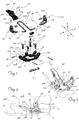
Figure 1 : is an exploded view of the toe-piece according to the present invention; -
Figure 2 : is a perspective view of the toe-piece according toFig. 1 in the rest condition with the jaws closed; -
Figure 3 : is a side view of the toe-piece shown inFig. 1 ; -
Figure 4 : is a top plan view of the toe-piece shown inFig. 1 ; -
Figures 5 and 6 : show, respectively, a front view and top plan view of the detail of the jaws of the toe-piece and the elastic operating element in the condition where the toe-piece is closed; -
Figs. 7 and 8 : show, respectively, a perspective and top-plan view of the toe-piece according to the invention in the condition where the jaws are open for inserting the toe of the boot; -
Figs. 9 and 10 : show, respectively, a front view and top plan view of the detail of the jaws of the toe-piece and of the elastic operating element in the condition where the toe-piece is open; -
Figs. 11 and 12 : show respectively a view, from above, of the toe-piece according to the invention with the means for adjusting the force of the elastic element and a top plan view of a first condition of deformation thereof; -
Figs. 13 and 14 : show respectively views which are similar to those ofFigs. 11 and 12 for different adjustment of the force of the elastic element; -
Figs. 15, 16 and 17 : show respectively side views of the different positions of the lever for operating the elastic element in the different conditions of use of the toe-piece; and -
Figure 18 : shows an example of a variation of embodiment of the toe-piece according to the invention. - As shown in
Fig. 1 and with reference to the examples of orientation shown in the figures whereby the front is assumed to be the part of the toe-piece proximal, during use, to the tip of theski 1 and the rear is assumed to be the opposite end, towards the tail end of the ski, and a set of three axes are conventionally assumed to be - merely for the sake of easier description - a longitudinal axis X-X along the length of the toe-piece, transverse axis Y-Y along the width and vertical axis Z-Z orthogonal to the first two axes, the toe-piece according to the invention substantially comprises: - a
base plate 10 extending substantially in the plane X-Y and provided withholes 11 for fixing to the ski by means ofcorresponding screws 11a; theplate 10 comprises in turn:- a first pair of vertically protruding uprights (12) situated opposite each other in the longitudinal direction X-X and arranged along a first
longitudinal edge 10a of thebase plate 10; - a second pair of
vertical uprights 12 situated opposite each other in the longitudinal direction X-X and arranged, symmetrically with respect to thefirst pair 12, on thelongitudinal edge 10b of thebase plate 10 opposite to the first edge;
- a first pair of vertically protruding uprights (12) situated opposite each other in the longitudinal direction X-X and arranged along a first
- The
base 10 also has arelief 15 arranged along its front transverse edge 10c and extending in the transverse direction Y-Y by an amount slightly smaller than the interaxial distance L between twolongitudinal arms 31b of a U-shapedelastic element 30 described below, so as to allowsaid arms 31b to pass in the vertical direction Z-Z. - In its top part the
relief 15 has a through-hole 15a in the transverse direction Y-Y suitable for inserting atransverse pin 16 with a length such that itsopposite ends 16a project transversely from therelief 15 by an amount such as to overlap thelongitudinal arms 31b of the "U", so as to interfere with them and prevent them from coming out during the various stages of operation of the toe-piece. - The
base 10 has, connected thereto, first andsecond jaws 20 situated opposite each other and symmetrical with respect to a longitudinal axis X-X approximately passing through the centre of the toe-piece; eachjaw 20 is substantially formed by: - a
vertical arm 21, which is substantially perpendicular to thebase 10 and provided with a respectiveconical pin 22 extending in the transverse direction Y-Y towards the inside of the toe-piece parallel to said base and designed to engage with a respective seat in thetoe 2a of a ski-boot 2 (only schematically indicated by means of broken lines inFig. 3 ); - a
transverse arm 21b substantially parallel to thebase 10, the inner free end of which has aseat 23 extending towards the inside of the said support arm; - each
jaw 20 also has a transverse through-hole 24 formed in the longitudinal direction X-X and designed to receive one of saidpins 13 which therefore forms the element for constraining the jaw to therespective uprights 12 and a longitudinal axis of rotation of the respective jaw between a normal closed rest position for holding the toe of the boot (Figs. 2 and 3 ) and an open position (Figs. 7 and 8 ) designed to allow the toe of the boot to enter inside the toe-piece; - an
elastic element 30 preferably formed by a single body in the form of a "U" with- a
base 31a extending in the transverse direction Y-Y and positioned in front of and outside of thebase plate 10 in the longitudinal direction X-X;
- a
-
arms 31b of the "U" which extend in the longitudinal direction from thebase 31a and have - a respective rear
free end 32 bent outwards in the transverse direction Y-Y and towards therespective seat 23 of thetransverse arm 21b of therespective jaw 20; - the
free end 32 is connected to the respectivelongitudinal arm 31b by means of a curved section forming a relative angle α in the plane X-Y and an acute angle β with a plane (X-Y) parallel to thebase plate 10; a variation in the angle β will determine a relative elastic deformation of eachend 32 and the respectivelongitudinal arm 31b, the effects of which as regards operation of the toe-piece will emerge more clearly below. Eachend 32 of the spring is housed inside therespective seat 23 of thejaw 20. Preferably theends 32 are housed inside the respective seat with slight play, so as to allow a minimum freedom of relative movement between the end and seat, without however the possibility of the former coming out of the latter. - In a preferred embodiment a small ball 32b is arranged between the
free end 32 of thearm 31b and the blind bottom of therespective seat 23 and is designed to facilitate rotation of the spring inside the seat during operation thereof. - In the example of embodiment shown in
Figs. 1-5 , theelastic element 30 can therefore be operated by means of pressure applied to thebase 31a of the "U" so as to switch from a raised rest position for keeping thejaws 20 in the closed position for holding the toe of the boot, into a lowered position, for rotational operation of the jaws towards the open position for inserting the toe. The flat parts of thebase 10 adjacent to thesides 15a of the raisedelement 15 form the reaction fulcrum for rotation of thearms 31b. In addition, thesides 15a of the raisedelement 15 act preferably as reaction fulcrums for transverse deformation (curving) of thearms 31b during opening of thejaws 20. - Preferably, the
transverse base 31a of the "U" is inserted inside a respective centraltransverse eyelet 41a of anoperating lever 40 arranged in front of the toe-piece and the boot and formed by abody 41 extending in the longitudinal direction X-X; in this way thebase 31a of the "U" forms a transverse axis of rotation ofsaid lever 40. - The
body 41 of the lever comprises at least onepart 41b behind saideyelet 41a in the longitudinal direction X-X, with a transverse dimension Y-Y suitable for being contained between thearms 31b of the "U" and having a freerear front surface 41c which is substantially flat for resting on the top surface S of the ski. - The bottom
free end 41b of thelever 40 also has two teeth 41e projecting outwards in opposite senses of the transverse direction Y-Y and designed to prevent rotation of thelever 40, by abutting against the lowerrespective arm 31b of the "U". - The front
free end 41d of thelever 40 is configured so that it may be easily operated by the user, in particular easily pushed downwards in the vertical direction Z-Z. - As will become clear below, the
operating lever 40 facilitates operation of theelastic element 30 and therefore opening of thejaws 20 into the position for inserting the toe of the boot as well as locking of the elastic element and therefore the jaws in the closed position for holding the toe of the boot. - With the configuration described operation of the toe-piece is as follows:
- -) starting from a normal rest position (
Figs. 2-3 ) withjaws 20 in the closed position, U-shaped elastic means (in the example shown fitted with a - preferred but optional - operating lever 40) witharms 31b of the "U" raised in the vertical direction Z-Z and operatinglever 40 arranged parallel to the said arms with therear part 41b inserted between thearms 31b and rotationally locked by the said teeth 41e bearing against thearms 31b, - -) a pressure is applied, substantially in the vertical direction Z-Z, onto the base of the "U" of the
elastic element 30, by pressing downwards (Fig. 7 ) thefree front end 41d of thelever 40 which, since it is locked on thearms 31b of the "U" by the teeth 41e, causes lowering of thebase 31a and consequent upwards rotation of the opposite end of thearms 31b which is connected to thebent ends 32 that undergo simultaneous elastic deformation which produces a movement so that the opposite bent ends 32:- converge towards each other in the transverse direction Y-Y and towards the inside of the toe-piece (the angle α is reduced (α'<α)) (
Fig. 10 ); - raise the respective curved connecting sections upwards in the vertical direction Z-Z, reducing the angle β (β'<β)) (
Fig. 9 ) and being deformed elastically with respect to the rest position; - push against the associated
transverse arm 21b of thejaws 20 causing a clockwise rotation of the same about therespective pins 13 into an open position suitable for insertion of the boot.
- converge towards each other in the transverse direction Y-Y and towards the inside of the toe-piece (the angle α is reduced (α'<α)) (
- Releasing the front end of the
lever 40 and therefore the base of the "U" causes the elastic return of the bent ends 32 towards the rest position and therefore the counter-rotation and the elastic return of theelastic element 30 into the raised rest position (Fig. 6 ) with consequent rotation, in the opposite, counter-clockwise, direction of the jaws (Fig. 5 ) which return into the initial closed condition for holding the toe of the boot. - Once the toe of the boot has been engaged it is possible to operate, if present, the
operating lever 40, causing it to rotate in the clockwise direction in order to define different conditions of use. - In greater detail:
- --)
lever 40 kept in the inclined position inside thearms 31b (Fig. 15 ) : if the boot is acted on by transverse/torsional forces - schematically indicated by the arrow F - with sufficient modulus in the transverse direction Y-Y, a corresponding thrust is produced on thevertical arm 21a of thejaws 20 which rotates so as to open together with the transverse arms and against the resistive action of theelastic element 30; - --) if the force F is not sufficiently high to manage to overcome the total resistance of the
elastic element 30, the latter, reacting, will again bring thejaws 20 and therefore the entire toe-piece into the closed position, producing an automatic self-centring effect; - --) if the force F is such as to overcome the total resistance of the
elastic element 30, the latter may no longer retain thejaws 20 which will rotate into their open position, causing release of the toe of the boot which will come out of the toe-piece.- -) if it is wished to walk uphill, a situation where the boot is constrained to the ski only at the toe, the operating
lever 40 will be preferably rotationally operated so as to bring the rearfree surface 41c into contact against the top surface S of the ski; in this condition the operatinglever 40 locks the elastic means 30 in the raised position, preventing opening of thejaws 20. This option is advantageous also in extreme downhill skiing conditions, where it is required to avoid at all costs possible accidental safety release of the toe-piece.
- -) if it is wished to walk uphill, a situation where the boot is constrained to the ski only at the toe, the operating
- It is therefore clear how, by varying the resistance of the
elastic element 30, it is possible to modify the safety release value of the toe-piece, it being therefore possible to choose a resistive force of the elastic element suitable for the weight and the skiing style of the athlete or end user. This may be achieved by varying the thickness/diameter of thearms 31b of the elastic element or the material from which they are made. For this purpose and as shown inFigs. 11-14 , it is also possible to optionally fit means 50 for adjusting the elastic thrusting force acting on the jaws of the toe-piece so as to be able to modify the safety release value of the toe-piece and choose a resistive force of the elastic element which is most suited to the weight and skiing style of the athlete or end user. - In detail,
Figs. 11 and 12 show a preferred embodiment of the adjusting means 50 which take the form of a slider 51 with suitably concave opposite transverse ends 51a for engagement with thearms 31b of the "U" on which it is therefore able to slide in the longitudinal direction from a position more retracted at the rear (Figs. 11 and 12 ) to a position more advanced at the front (Figs. 13 and 14 ). The presence of theslider 50 displaces the reaction fulcrum for curving of theelastic element 30 from thesides 15a of the raisedpart 15 to theconcave sides 51a of saidslider 50, resulting in a different overall elasticity of the elastic element and therefore resistance to release of the toe-piece. - The slider may be displaced in a substantially continuous manner, allowing a corresponding modulation of the resistance to release of the toe-piece and, once the desired position has been reached, which may be marked by notches or an indication of the corresponding reaction kilograms, the slider may be locked by means of a locking plate 52 which can be locked to the slider by means of a fixing grub-screw 53 and the opposite ends of which push against the
arms 31b of the "U". - During use the slider may be locked in position along the
arms 31b by tightening the grub-screw 53 against said slider, while in order to vary the position of the slider it is sufficient to slacken the grub-screw, slide the slider to the desired position and then tighten again the grub-screw 53. Optionally the toe-piece may be provided with anelement 60 for inserting so-called ski-touring rampants (shown only inFig. 1 ) positioned at the rear, in the longitudinal direction X-X, of thebase plate 100. The element 60 (Fig. 1 ) extends transversely and has a cross-sectional form (along a plane X-Z) which is substantially in the form of a "C" open towards the toe-piece itself and with a plate provided with holes for receiving the screws for fixing thebase 100, it being fastened thereto by said screws once assembly has been performed. - As shown in
Fig. 18 , it is envisaged moreover that the toe-piece according to the invention may be realized with a different configuration of theelastic element 130 which, in this version, has a relative angle β, between the bent ends 132 of the respective arms 31 and a plane parallel to the plane of the base plate, with a sign opposite to that of the preceding case; this results in a stable position of theelastic element 130 rotated in the anti-clockwise direction downwards and a consequent rest configuration of the toe-piece withjaws 20 rotated in the open position. - Operation of the toe-piece in this case occurs by means of a pulling force exerted on the base 31 of the
elastic element 130 which causes the downwards rotation of theends 132 connected to said jaws, resulting in elastic deformation of the former with respect to thecorresponding arm 31b such as to bring the elastic element into a second stable position with the jaws rotated into the closed position for engagement with the toe of the boot. Preferably, in this case also, the presence and the rotation of the operatinglever 40 may determine the various conditions of use of the toe-piece, as already described for the first embodiment thereof. It is therefore clear how, with the U-shaped elastic element according to the invention, it is possible to obtain a substantial simplification as regards both the number and weight of the components forming the toe-piece and therefore of the toe-piece as a whole, as well as simplification of its operation which is less prone to faulty operation resulting from the particular conditions of use which are typically associated with ski-touring. - In addition, owing to the particular simplified configuration, it is also possible to improve adjustment of the resistance to release of the toe-piece in the case of transverse and/or torsional forces imparted by the boot, thereby ensuring greater safety during use.
- Although described in connection with a number of embodiments and a number of preferred examples of embodiment of the invention, it is understood that the scope of protection of the present patent is determined solely by the claims below.
Claims (13)
- Toe-piece for ski-touring bindings extending in a longitudinal lengthwise direction (X-X) of the toe-piece, transverse widthwise direction (Y-Y) and vertical direction (Z-Z), perpendicular to the aforementioned directions, and comprising:- a base plate (10) provided with holes (11) for fixing by means of screws (11a) to the surface (S) of a ski (1) extending in the longitudinal direction from a front tip (1a) to a rear tail-end, the plate (10) being coupled to:- two jaws (20) situated opposite each other and symmetrically with respect to a longitudinal axis (X-X), each with a transverse arm (21b) and a vertical arm (21a) provided with a respective transverse conical pin (22), which arms are designed to rotate about an axis (13) substantially parallel to the base plate (10) and to the longitudinal direction (X-X) between a closed/open position for retaining/inserting and releasing the toe (2a) of a ski-boot (2) and an open/closed position for releasing and inserting/retaining the toe (2a),- a single-piece elastic element (30;130) with two ends (32;132) cooperating with said transverse arms (21b) characterised in that said single-piece elastic element (30;130) is able to be operated from a rest position, corresponding to the closed/open position of the jaws (20), to a rotated and elastically deformed position for rotationally operating the jaws (20) into the open/closed position for inserting and releasing/retaining the toe (2a) of the ski-boot (2) inside the toe-piece.
- Toe-piece according to Claim 1, characterized in that said rest position of the elastic element (30) is rotated upwards/raised and in that operation is performed by applying pressure thereon.
- Toe-piece according to Claim 1, characterized in that said rest position of the elastic element (130) is rotated downwards/lowered and in that operation is performed by applying a pulling force thereon.
- Toe-piece according to Claim 1, characterized in that the base plate (10) comprises:- a first pair of protruding uprights (12) situated opposite each other in the longitudinal direction (X-X) and arranged along a first longitudinal edge (10a) of the base plate (10);- a second pair of vertical uprights (12) situated opposite each other in the longitudinal direction (X-X) and arranged, symmetrically with respect to the first pair (12), on a second longitudinal edge (10b) of the base plate (10) opposite to the first edge (10a);each upright (12) having a longitudinal through-hole (12a) designed to receive a longitudinal pin (13) for constraining the corresponding jaw to the respective uprights (12), said pin (13) forming a longitudinal axis for rotation of the respective jaw (20) between the normal closed position and the open position.
- Toe-piece according to any one of the preceding claims, characterized in that said elastic element (30;130) is formed by a U-shaped body with- a base (31a) of the "U" extending in the transverse direction (Y-Y) and positioned in front of and outside of the base plate (10) in the longitudinal direction (X-X);- arms (31b) of the "U" which extend in the longitudinal direction from the base (31a) and have- a respective rear free end (32; 132) bent outwards in the transverse direction (Y-Y) and towards a respective seat (23) of the transverse arm (21b) of the respective jaw (20), inside which seat (23) they are stably housed.
- Toe-piece according to the preceding claim, characterized in that the free ends (32;132) of the elastic element (30;130) are connected to the respective longitudinal arm (31b) by means of a curved section forming a relative angle (α) in a plane (X-Y) parallel to the base plate (10) and an acute angle (β) with a plane (X-Y) parallel to the base plate (10).
- Toe-piece according to any one of claims 5-6, characterized in that the base (10) has a relief (15) arranged along its front transverse edge (10c) and extending in the transverse direction (Y-Y) by an amount slightly smaller than the interaxial distance (L) between the two longitudinal arms (31b) of the U-shaped elastic element (30) and such as to allow insertion between said arms (31b) in the vertical direction (Z-Z).
- Toe-piece according to the preceding claim, characterized in that in its top part the relief (15) has a through-hole (15a) in the transverse direction (Y-Y) suitable for inserting a transverse pin (16), the pin (16) having a length such that its opposite ends (16a) project transversely from the relief (15) overlapping the longitudinal arms (31b) of the "U", in order to interfere with them in the vertical direction (Z-Z) and prevent them from coming out.
- Toe-piece according to the preceding claim, characterized in that the flat parts of the base (10), adjacent to the sides (15a) of the relief (15), form a reaction fulcrum for rotation of the longitudinal arms (31b) of the elastic element (30).
- Toe-piece according to any one of the preceding claims, characterized in that it comprises an operating lever (40), arranged in front of the base plate (10) and formed by a body (41) extending in the longitudinal direction (X-X) and having a central transverse eyelet (41a) inside which the transverse base (31a) of the "U" of the body of the elastic element (30;130) is inserted, said base forming a transverse axis of rotation of the said lever (40).
- Toe-piece according to any one of the preceding claims, characterized in that it comprises means (50) for adjusting the elastic resistive force of the elastic element (30;130) of the toe-piece, thereby adjusting the safety release value of the toe-piece.
- Toe-piece according to the preceding claims, characterized in that said adjusting means comprise a slider (51) with opposite transverse ends (51a) which are suitably concave for engagement with the arms (31b) of the "U" on which the slider may slide in the longitudinal direction.
- Toe-piece according to the preceding claim, characterized in that said adjusting means comprise a locking plate (52), the opposite ends of which press against the arms (31b) of the "U" and can be locked to the slider by means of a fixing grub-screw (53).
Applications Claiming Priority (1)
| Application Number | Priority Date | Filing Date | Title |
|---|---|---|---|
| ITMI20140901 | 2014-05-19 |
Publications (2)
| Publication Number | Publication Date |
|---|---|
| EP2946817A1 EP2946817A1 (en) | 2015-11-25 |
| EP2946817B1 true EP2946817B1 (en) | 2017-05-03 |
Family
ID=51230010
Family Applications (1)
| Application Number | Title | Priority Date | Filing Date |
|---|---|---|---|
| EP15167803.4A Active EP2946817B1 (en) | 2014-05-19 | 2015-05-15 | Toe-piece for ski-touring bindings |
Country Status (2)
| Country | Link |
|---|---|
| US (1) | US9440137B2 (en) |
| EP (1) | EP2946817B1 (en) |
Cited By (1)
| Publication number | Priority date | Publication date | Assignee | Title |
|---|---|---|---|---|
| US20210308552A1 (en) * | 2019-06-22 | 2021-10-07 | Salewa Sport Ag | Front unit for a touring binding |
Families Citing this family (5)
| Publication number | Priority date | Publication date | Assignee | Title |
|---|---|---|---|---|
| EP2929919B1 (en) * | 2014-04-09 | 2018-05-30 | Salomon S.A.S. | Ski binding |
| DE102017120701A1 (en) * | 2017-09-07 | 2019-03-07 | Marker Deutschland Gmbh | Ultralight forehead |
| EP3566754B1 (en) * | 2018-05-08 | 2022-08-17 | Fritschi AG - Swiss Bindings | Front skibinding |
| DE102020203280A1 (en) * | 2020-03-13 | 2021-09-16 | Salewa Sport Ag | Front unit for a ski binding with a defined opening dimension |
| IT202000012502A1 (en) * | 2020-05-27 | 2021-11-27 | Atk Sports S R L | FRONT INSERT FOR SKI MOUNTAINEERING BOOTS, FOR ATTACHING THE BOOT TO A SKI MOUNTAINEERING BINDING |
Citations (1)
| Publication number | Priority date | Publication date | Assignee | Title |
|---|---|---|---|---|
| EP2687275A1 (en) * | 2012-07-19 | 2014-01-22 | Salomon S.A.S. | Front retaining devices of a glideboard |
Family Cites Families (14)
| Publication number | Priority date | Publication date | Assignee | Title |
|---|---|---|---|---|
| JPS4855970U (en) * | 1971-10-27 | 1973-07-18 | ||
| DE2906485C2 (en) * | 1979-02-20 | 1982-06-16 | Geze Gmbh, 7250 Leonberg | Cross-country binding with a binding part that supports a front sole overhang |
| US4322090A (en) * | 1980-02-13 | 1982-03-30 | Loughney Charles E | Ski mountaineering binding |
| DE3204650A1 (en) * | 1982-02-10 | 1983-08-18 | Marker Patentverwertungsgesellschaft mbH, 6340 Baar | TOURING SKI BINDING |
| ITMI20051429A1 (en) * | 2005-07-22 | 2007-01-23 | Ski Trab S R L | TIP FOR SKI ATTACHMENTS |
| US8439389B2 (en) * | 2008-04-03 | 2013-05-14 | G3 Genuine Guide Gear Inc. | Toe unit for alpine touring binding |
| DE202010000614U1 (en) * | 2010-01-05 | 2011-05-26 | Salewa Sport Ag | Ski boot and binding system comprising a ski boot and a ski binding |
| DE102010029647A1 (en) * | 2010-06-02 | 2011-12-08 | Salewa Sport Ag | touring binding |
| DE102012201816B4 (en) * | 2012-02-07 | 2022-10-20 | Fritz Barthel | Front unit for a gliding board binding having first and second engagement means |
| ITBO20120243A1 (en) * | 2012-05-04 | 2013-11-05 | Atk Race Srl | TIP FOR SKI-MOUNTAINEER'S ATTACK |
| DE102012207959B4 (en) * | 2012-05-11 | 2020-11-12 | Fritz Barthel | Front unit of a gliding board binding and gliding board binding |
| FR2991592B1 (en) * | 2012-06-12 | 2016-08-26 | Rossignol Sa | TORSIONALLY AUTOMATIC TRIGGER STOP |
| ITBO20120645A1 (en) * | 2012-11-28 | 2014-05-29 | Atk Race Srl | DEVICE FOR THE REMOVABLE LOCKING OF THE CENTRAL-FRONT PART OF A SKIING BOOT AT THE SKI TABLE TO IMPLEMENT THE TELEMARK TECHNIQUE |
| FR3002460B1 (en) * | 2013-02-22 | 2017-08-25 | Rossignol Sa | TORSIONALLY AUTOMATIC TRIGGER STOP |
-
2015
- 2015-05-15 EP EP15167803.4A patent/EP2946817B1/en active Active
- 2015-05-19 US US14/716,439 patent/US9440137B2/en active Active
Patent Citations (1)
| Publication number | Priority date | Publication date | Assignee | Title |
|---|---|---|---|---|
| EP2687275A1 (en) * | 2012-07-19 | 2014-01-22 | Salomon S.A.S. | Front retaining devices of a glideboard |
Cited By (1)
| Publication number | Priority date | Publication date | Assignee | Title |
|---|---|---|---|---|
| US20210308552A1 (en) * | 2019-06-22 | 2021-10-07 | Salewa Sport Ag | Front unit for a touring binding |
Also Published As
| Publication number | Publication date |
|---|---|
| EP2946817A1 (en) | 2015-11-25 |
| US20150328529A1 (en) | 2015-11-19 |
| US9440137B2 (en) | 2016-09-13 |
Similar Documents
| Publication | Publication Date | Title |
|---|---|---|
| EP2946817B1 (en) | Toe-piece for ski-touring bindings | |
| EP1907078B1 (en) | Toe-piece for ski bindings | |
| EP2281614B1 (en) | Heel piece with two-armed front fork engageable with pins on a boot | |
| US8439389B2 (en) | Toe unit for alpine touring binding | |
| US10010782B2 (en) | Heel-piece for binding a boot on a gliding board | |
| US5944337A (en) | Automatic binding device | |
| EP2243388B1 (en) | Ski-boot with means for actuating corresponding engaging members of ski-touring bindings | |
| US9308433B2 (en) | Front unit for a binding device and retractable pins device | |
| US5518264A (en) | Free heel/anterior release ski binding | |
| EP2547410B1 (en) | Improved binding system for skis with the possibility of lifting the tip of the footwear | |
| US9452343B2 (en) | SKI binding with forefoot fixing module | |
| RU2526289C2 (en) | Flexor with clamp | |
| CS219884B2 (en) | Runner binding | |
| US10946265B2 (en) | Holding element for a ski boot with a tiltable fitting pedal | |
| EP3155920A1 (en) | Anchoring plate for a closure device for a sports footwear | |
| EP2911541B1 (en) | Ski boot | |
| WO2009153615A1 (en) | Multi-position heel piece for ski mountaineering bindings | |
| EP2707111B1 (en) | Ski binding device for fastening a mountaineering boot on a downhill ski or the like | |
| US9016713B2 (en) | Ski binding | |
| US4607859A (en) | Safety ski binding | |
| US11524220B2 (en) | Ski binding | |
| EP0448009B1 (en) | Safety ski binding | |
| EP2489415A1 (en) | Toe piece for touring binding | |
| JP2013530790A (en) | Strap for snowboard binding | |
| JPS5836988B2 (en) | Kaihoji Zainoski Binding |
Legal Events
| Date | Code | Title | Description |
|---|---|---|---|
| PUAI | Public reference made under article 153(3) epc to a published international application that has entered the european phase |
Free format text: ORIGINAL CODE: 0009012 |
|
| AK | Designated contracting states |
Kind code of ref document: A1 Designated state(s): AL AT BE BG CH CY CZ DE DK EE ES FI FR GB GR HR HU IE IS IT LI LT LU LV MC MK MT NL NO PL PT RO RS SE SI SK SM TR |
|
| AX | Request for extension of the european patent |
Extension state: BA ME |
|
| RBV | Designated contracting states (corrected) |
Designated state(s): AL AT BE BG CH CY CZ DE DK EE ES FI FR GB GR HR HU IE IS IT LI LT LU LV MC MK MT NL NO PL PT RO RS SE SI SK SM TR |
|
| 17P | Request for examination filed |
Effective date: 20160519 |
|
| RIC1 | Information provided on ipc code assigned before grant |
Ipc: A63C 9/086 20120101ALI20160930BHEP Ipc: A63C 9/08 20120101AFI20160930BHEP Ipc: A63C 9/085 20120101ALI20160930BHEP |
|
| GRAP | Despatch of communication of intention to grant a patent |
Free format text: ORIGINAL CODE: EPIDOSNIGR1 |
|
| INTG | Intention to grant announced |
Effective date: 20161124 |
|
| GRAS | Grant fee paid |
Free format text: ORIGINAL CODE: EPIDOSNIGR3 |
|
| GRAA | (expected) grant |
Free format text: ORIGINAL CODE: 0009210 |
|
| AK | Designated contracting states |
Kind code of ref document: B1 Designated state(s): AL AT BE BG CH CY CZ DE DK EE ES FI FR GB GR HR HU IE IS IT LI LT LU LV MC MK MT NL NO PL PT RO RS SE SI SK SM TR |
|
| REG | Reference to a national code |
Ref country code: GB Ref legal event code: FG4D |
|
| REG | Reference to a national code |
Ref country code: AT Ref legal event code: REF Ref document number: 889328 Country of ref document: AT Kind code of ref document: T Effective date: 20170515 Ref country code: CH Ref legal event code: EP |
|
| REG | Reference to a national code |
Ref country code: FR Ref legal event code: PLFP Year of fee payment: 3 Ref country code: IE Ref legal event code: FG4D |
|
| REG | Reference to a national code |
Ref country code: DE Ref legal event code: R096 Ref document number: 602015002495 Country of ref document: DE |
|
| REG | Reference to a national code |
Ref country code: NL Ref legal event code: MP Effective date: 20170503 |
|
| REG | Reference to a national code |
Ref country code: AT Ref legal event code: MK05 Ref document number: 889328 Country of ref document: AT Kind code of ref document: T Effective date: 20170503 |
|
| REG | Reference to a national code |
Ref country code: LT Ref legal event code: MG4D |
|
| PG25 | Lapsed in a contracting state [announced via postgrant information from national office to epo] |
Ref country code: HR Free format text: LAPSE BECAUSE OF FAILURE TO SUBMIT A TRANSLATION OF THE DESCRIPTION OR TO PAY THE FEE WITHIN THE PRESCRIBED TIME-LIMIT Effective date: 20170503 Ref country code: ES Free format text: LAPSE BECAUSE OF FAILURE TO SUBMIT A TRANSLATION OF THE DESCRIPTION OR TO PAY THE FEE WITHIN THE PRESCRIBED TIME-LIMIT Effective date: 20170503 Ref country code: AT Free format text: LAPSE BECAUSE OF FAILURE TO SUBMIT A TRANSLATION OF THE DESCRIPTION OR TO PAY THE FEE WITHIN THE PRESCRIBED TIME-LIMIT Effective date: 20170503 Ref country code: FI Free format text: LAPSE BECAUSE OF FAILURE TO SUBMIT A TRANSLATION OF THE DESCRIPTION OR TO PAY THE FEE WITHIN THE PRESCRIBED TIME-LIMIT Effective date: 20170503 Ref country code: NO Free format text: LAPSE BECAUSE OF FAILURE TO SUBMIT A TRANSLATION OF THE DESCRIPTION OR TO PAY THE FEE WITHIN THE PRESCRIBED TIME-LIMIT Effective date: 20170803 Ref country code: GR Free format text: LAPSE BECAUSE OF FAILURE TO SUBMIT A TRANSLATION OF THE DESCRIPTION OR TO PAY THE FEE WITHIN THE PRESCRIBED TIME-LIMIT Effective date: 20170804 Ref country code: LT Free format text: LAPSE BECAUSE OF FAILURE TO SUBMIT A TRANSLATION OF THE DESCRIPTION OR TO PAY THE FEE WITHIN THE PRESCRIBED TIME-LIMIT Effective date: 20170503 |
|
| PG25 | Lapsed in a contracting state [announced via postgrant information from national office to epo] |
Ref country code: PL Free format text: LAPSE BECAUSE OF FAILURE TO SUBMIT A TRANSLATION OF THE DESCRIPTION OR TO PAY THE FEE WITHIN THE PRESCRIBED TIME-LIMIT Effective date: 20170503 Ref country code: BG Free format text: LAPSE BECAUSE OF FAILURE TO SUBMIT A TRANSLATION OF THE DESCRIPTION OR TO PAY THE FEE WITHIN THE PRESCRIBED TIME-LIMIT Effective date: 20170803 Ref country code: RS Free format text: LAPSE BECAUSE OF FAILURE TO SUBMIT A TRANSLATION OF THE DESCRIPTION OR TO PAY THE FEE WITHIN THE PRESCRIBED TIME-LIMIT Effective date: 20170503 Ref country code: SE Free format text: LAPSE BECAUSE OF FAILURE TO SUBMIT A TRANSLATION OF THE DESCRIPTION OR TO PAY THE FEE WITHIN THE PRESCRIBED TIME-LIMIT Effective date: 20170503 Ref country code: LV Free format text: LAPSE BECAUSE OF FAILURE TO SUBMIT A TRANSLATION OF THE DESCRIPTION OR TO PAY THE FEE WITHIN THE PRESCRIBED TIME-LIMIT Effective date: 20170503 Ref country code: NL Free format text: LAPSE BECAUSE OF FAILURE TO SUBMIT A TRANSLATION OF THE DESCRIPTION OR TO PAY THE FEE WITHIN THE PRESCRIBED TIME-LIMIT Effective date: 20170503 Ref country code: IS Free format text: LAPSE BECAUSE OF FAILURE TO SUBMIT A TRANSLATION OF THE DESCRIPTION OR TO PAY THE FEE WITHIN THE PRESCRIBED TIME-LIMIT Effective date: 20170903 |
|
| PG25 | Lapsed in a contracting state [announced via postgrant information from national office to epo] |
Ref country code: EE Free format text: LAPSE BECAUSE OF FAILURE TO SUBMIT A TRANSLATION OF THE DESCRIPTION OR TO PAY THE FEE WITHIN THE PRESCRIBED TIME-LIMIT Effective date: 20170503 Ref country code: CZ Free format text: LAPSE BECAUSE OF FAILURE TO SUBMIT A TRANSLATION OF THE DESCRIPTION OR TO PAY THE FEE WITHIN THE PRESCRIBED TIME-LIMIT Effective date: 20170503 Ref country code: DK Free format text: LAPSE BECAUSE OF FAILURE TO SUBMIT A TRANSLATION OF THE DESCRIPTION OR TO PAY THE FEE WITHIN THE PRESCRIBED TIME-LIMIT Effective date: 20170503 Ref country code: RO Free format text: LAPSE BECAUSE OF FAILURE TO SUBMIT A TRANSLATION OF THE DESCRIPTION OR TO PAY THE FEE WITHIN THE PRESCRIBED TIME-LIMIT Effective date: 20170503 Ref country code: SK Free format text: LAPSE BECAUSE OF FAILURE TO SUBMIT A TRANSLATION OF THE DESCRIPTION OR TO PAY THE FEE WITHIN THE PRESCRIBED TIME-LIMIT Effective date: 20170503 |
|
| REG | Reference to a national code |
Ref country code: DE Ref legal event code: R097 Ref document number: 602015002495 Country of ref document: DE |
|
| REG | Reference to a national code |
Ref country code: IE Ref legal event code: MM4A |
|
| PG25 | Lapsed in a contracting state [announced via postgrant information from national office to epo] |
Ref country code: IT Free format text: LAPSE BECAUSE OF FAILURE TO SUBMIT A TRANSLATION OF THE DESCRIPTION OR TO PAY THE FEE WITHIN THE PRESCRIBED TIME-LIMIT Effective date: 20170503 Ref country code: SM Free format text: LAPSE BECAUSE OF FAILURE TO SUBMIT A TRANSLATION OF THE DESCRIPTION OR TO PAY THE FEE WITHIN THE PRESCRIBED TIME-LIMIT Effective date: 20170503 |
|
| PLBE | No opposition filed within time limit |
Free format text: ORIGINAL CODE: 0009261 |
|
| STAA | Information on the status of an ep patent application or granted ep patent |
Free format text: STATUS: NO OPPOSITION FILED WITHIN TIME LIMIT |
|
| PG25 | Lapsed in a contracting state [announced via postgrant information from national office to epo] |
Ref country code: LU Free format text: LAPSE BECAUSE OF NON-PAYMENT OF DUE FEES Effective date: 20170515 |
|
| 26N | No opposition filed |
Effective date: 20180206 |
|
| REG | Reference to a national code |
Ref country code: BE Ref legal event code: MM Effective date: 20170531 |
|
| PG25 | Lapsed in a contracting state [announced via postgrant information from national office to epo] |
Ref country code: IE Free format text: LAPSE BECAUSE OF NON-PAYMENT OF DUE FEES Effective date: 20170515 |
|
| PG25 | Lapsed in a contracting state [announced via postgrant information from national office to epo] |
Ref country code: SI Free format text: LAPSE BECAUSE OF FAILURE TO SUBMIT A TRANSLATION OF THE DESCRIPTION OR TO PAY THE FEE WITHIN THE PRESCRIBED TIME-LIMIT Effective date: 20170503 |
|
| REG | Reference to a national code |
Ref country code: FR Ref legal event code: PLFP Year of fee payment: 4 |
|
| PG25 | Lapsed in a contracting state [announced via postgrant information from national office to epo] |
Ref country code: BE Free format text: LAPSE BECAUSE OF NON-PAYMENT OF DUE FEES Effective date: 20170531 |
|
| PG25 | Lapsed in a contracting state [announced via postgrant information from national office to epo] |
Ref country code: MT Free format text: LAPSE BECAUSE OF NON-PAYMENT OF DUE FEES Effective date: 20170515 |
|
| REG | Reference to a national code |
Ref country code: CH Ref legal event code: PL |
|
| PG25 | Lapsed in a contracting state [announced via postgrant information from national office to epo] |
Ref country code: LI Free format text: LAPSE BECAUSE OF NON-PAYMENT OF DUE FEES Effective date: 20180531 Ref country code: CH Free format text: LAPSE BECAUSE OF NON-PAYMENT OF DUE FEES Effective date: 20180531 |
|
| PG25 | Lapsed in a contracting state [announced via postgrant information from national office to epo] |
Ref country code: HU Free format text: LAPSE BECAUSE OF FAILURE TO SUBMIT A TRANSLATION OF THE DESCRIPTION OR TO PAY THE FEE WITHIN THE PRESCRIBED TIME-LIMIT; INVALID AB INITIO Effective date: 20150515 Ref country code: MC Free format text: LAPSE BECAUSE OF FAILURE TO SUBMIT A TRANSLATION OF THE DESCRIPTION OR TO PAY THE FEE WITHIN THE PRESCRIBED TIME-LIMIT Effective date: 20170503 |
|
| PG25 | Lapsed in a contracting state [announced via postgrant information from national office to epo] |
Ref country code: CY Free format text: LAPSE BECAUSE OF FAILURE TO SUBMIT A TRANSLATION OF THE DESCRIPTION OR TO PAY THE FEE WITHIN THE PRESCRIBED TIME-LIMIT Effective date: 20170503 |
|
| PG25 | Lapsed in a contracting state [announced via postgrant information from national office to epo] |
Ref country code: MK Free format text: LAPSE BECAUSE OF FAILURE TO SUBMIT A TRANSLATION OF THE DESCRIPTION OR TO PAY THE FEE WITHIN THE PRESCRIBED TIME-LIMIT Effective date: 20170503 |
|
| GBPC | Gb: european patent ceased through non-payment of renewal fee |
Effective date: 20190515 |
|
| PG25 | Lapsed in a contracting state [announced via postgrant information from national office to epo] |
Ref country code: TR Free format text: LAPSE BECAUSE OF FAILURE TO SUBMIT A TRANSLATION OF THE DESCRIPTION OR TO PAY THE FEE WITHIN THE PRESCRIBED TIME-LIMIT Effective date: 20170503 |
|
| PG25 | Lapsed in a contracting state [announced via postgrant information from national office to epo] |
Ref country code: GB Free format text: LAPSE BECAUSE OF NON-PAYMENT OF DUE FEES Effective date: 20190515 |
|
| PG25 | Lapsed in a contracting state [announced via postgrant information from national office to epo] |
Ref country code: PT Free format text: LAPSE BECAUSE OF FAILURE TO SUBMIT A TRANSLATION OF THE DESCRIPTION OR TO PAY THE FEE WITHIN THE PRESCRIBED TIME-LIMIT Effective date: 20170503 |
|
| PG25 | Lapsed in a contracting state [announced via postgrant information from national office to epo] |
Ref country code: AL Free format text: LAPSE BECAUSE OF FAILURE TO SUBMIT A TRANSLATION OF THE DESCRIPTION OR TO PAY THE FEE WITHIN THE PRESCRIBED TIME-LIMIT Effective date: 20170503 |
|
| PGFP | Annual fee paid to national office [announced via postgrant information from national office to epo] |
Ref country code: FR Payment date: 20230523 Year of fee payment: 9 Ref country code: DE Payment date: 20230524 Year of fee payment: 9 |