EP1907078B1 - Toe-piece for ski bindings - Google Patents
Toe-piece for ski bindings Download PDFInfo
- Publication number
- EP1907078B1 EP1907078B1 EP06779929A EP06779929A EP1907078B1 EP 1907078 B1 EP1907078 B1 EP 1907078B1 EP 06779929 A EP06779929 A EP 06779929A EP 06779929 A EP06779929 A EP 06779929A EP 1907078 B1 EP1907078 B1 EP 1907078B1
- Authority
- EP
- European Patent Office
- Prior art keywords
- toe
- piece
- base
- piece according
- lever
- Prior art date
- Legal status (The legal status is an assumption and is not a legal conclusion. Google has not performed a legal analysis and makes no representation as to the accuracy of the status listed.)
- Not-in-force
Links
Images


Classifications
-
- A—HUMAN NECESSITIES
- A63—SPORTS; GAMES; AMUSEMENTS
- A63C—SKATES; SKIS; ROLLER SKATES; DESIGN OR LAYOUT OF COURTS, RINKS OR THE LIKE
- A63C9/00—Ski bindings
- A63C9/08—Ski bindings yieldable or self-releasing in the event of an accident, i.e. safety bindings
- A63C9/086—Ski bindings yieldable or self-releasing in the event of an accident, i.e. safety bindings using parts which are fixed on the shoe of the user and are releasable from the ski binding
-
- A—HUMAN NECESSITIES
- A63—SPORTS; GAMES; AMUSEMENTS
- A63C—SKATES; SKIS; ROLLER SKATES; DESIGN OR LAYOUT OF COURTS, RINKS OR THE LIKE
- A63C9/00—Ski bindings
- A63C9/02—Non-self-releasing bindings with swivel sole-plate or swivel parts, i.e. Ellefsen-type
-
- A—HUMAN NECESSITIES
- A63—SPORTS; GAMES; AMUSEMENTS
- A63C—SKATES; SKIS; ROLLER SKATES; DESIGN OR LAYOUT OF COURTS, RINKS OR THE LIKE
- A63C9/00—Ski bindings
- A63C9/08—Ski bindings yieldable or self-releasing in the event of an accident, i.e. safety bindings
- A63C9/0807—Ski bindings yieldable or self-releasing in the event of an accident, i.e. safety bindings for both towing and downhill skiing
-
- A—HUMAN NECESSITIES
- A63—SPORTS; GAMES; AMUSEMENTS
- A63C—SKATES; SKIS; ROLLER SKATES; DESIGN OR LAYOUT OF COURTS, RINKS OR THE LIKE
- A63C9/00—Ski bindings
- A63C9/08—Ski bindings yieldable or self-releasing in the event of an accident, i.e. safety bindings
- A63C9/085—Ski bindings yieldable or self-releasing in the event of an accident, i.e. safety bindings with sole hold-downs, e.g. swingable
- A63C9/08507—Ski bindings yieldable or self-releasing in the event of an accident, i.e. safety bindings with sole hold-downs, e.g. swingable with a plurality of mobile jaws
- A63C9/08521—Ski bindings yieldable or self-releasing in the event of an accident, i.e. safety bindings with sole hold-downs, e.g. swingable with a plurality of mobile jaws pivoting about a vertical axis, e.g. side release
-
- A—HUMAN NECESSITIES
- A63—SPORTS; GAMES; AMUSEMENTS
- A63C—SKATES; SKIS; ROLLER SKATES; DESIGN OR LAYOUT OF COURTS, RINKS OR THE LIKE
- A63C9/00—Ski bindings
- A63C9/08—Ski bindings yieldable or self-releasing in the event of an accident, i.e. safety bindings
- A63C9/085—Ski bindings yieldable or self-releasing in the event of an accident, i.e. safety bindings with sole hold-downs, e.g. swingable
- A63C9/08557—Details of the release mechanism
- A63C9/08564—Details of the release mechanism using cam or slide surface
-
- A—HUMAN NECESSITIES
- A63—SPORTS; GAMES; AMUSEMENTS
- A63C—SKATES; SKIS; ROLLER SKATES; DESIGN OR LAYOUT OF COURTS, RINKS OR THE LIKE
- A63C9/00—Ski bindings
- A63C9/08—Ski bindings yieldable or self-releasing in the event of an accident, i.e. safety bindings
- A63C9/085—Ski bindings yieldable or self-releasing in the event of an accident, i.e. safety bindings with sole hold-downs, e.g. swingable
- A63C9/08557—Details of the release mechanism
- A63C9/08578—Details of the release mechanism using a plurality of biasing elements
-
- A—HUMAN NECESSITIES
- A63—SPORTS; GAMES; AMUSEMENTS
- A63C—SKATES; SKIS; ROLLER SKATES; DESIGN OR LAYOUT OF COURTS, RINKS OR THE LIKE
- A63C9/00—Ski bindings
- A63C9/08—Ski bindings yieldable or self-releasing in the event of an accident, i.e. safety bindings
- A63C9/085—Ski bindings yieldable or self-releasing in the event of an accident, i.e. safety bindings with sole hold-downs, e.g. swingable
- A63C9/08557—Details of the release mechanism
- A63C9/08585—Details of the release mechanism using transverse biasing element
-
- A—HUMAN NECESSITIES
- A63—SPORTS; GAMES; AMUSEMENTS
- A63C—SKATES; SKIS; ROLLER SKATES; DESIGN OR LAYOUT OF COURTS, RINKS OR THE LIKE
- A63C9/00—Ski bindings
- A63C9/20—Non-self-releasing bindings with special sole edge holders instead of toe-straps
Definitions
- the present invention relates to a toe-piece for ski bindings provided with safety release means for the toe of the ski boot.
- EP 0,199,098 describes, for example, known bindings of the type mentioned above which have, however, the drawback consisting in the fact that the toe-piece does not have independent means for releasing the boot in the transverse direction, as required in the event of a fall or a twisting movement during downhill skiing, said safety condition being achieved by means of corresponding means for operating the rear heel-piece, which is therefore very complex and heavy and results in an assembly which has poor rigidity and is awkward during fitting.
- the technical problem which is posed, therefore, is to provide a ski binding toe-piece able to achieve locking of the boot toe with the rigidity normally required for such applications and with the possibility of rotating the same toe about a horizontal axis, but at the same time able to allow the toe to come out of the toe-piece in the event of it being acted on by transverse forces, independently of the action of the heel-piece.
- this toe-piece should have small dimensions and a reduced weight, be easy and inexpensive to produce and assemble and be able to be fitted easily to skis using normal standardised connection means.
- a toe-piece for ski bindings comprising a fixed support base having two jaws, with a respective end pin, able to rotate about an axis substantially perpendicular to the support base so as to pass from an open position into a closed position for locking the toe of a ski boot, said jaws having a resistance arm co-operating with actuating means able to rotate about an axis perpendicular to the support base against the opposing action of resilient means integral with the said toe-piece, said actuating means being constrained to a sliding piece able to be displaced in both senses in the longitudinal direction upon actuation of associated operating means, so as to cause closing/opening of the two jaws.
- the toe-piece according to the invention comprises essentially:
- said operating lever 420 is provided with an eyelet 422 elongated in the longitudinal direction and receiving, inserted inside it, a button 430 with a gripping head 431 and fork-shaped body 432 able to be arranged over a longitudinal extension 313 of the lever 310 so as to lock/release rotation thereof.
- the sliding piece 350 is situated, in the vertical direction, between two strips 340 of material with a low coefficient of friction for facilitating displacement thereof with respect to the base and rotation of the lever (311).
- the operating principle of the toe-piece is as follows:
- Fig. 8 shows a first variation of embodiment of the toe-piece according to the present invention, in this configuration the operating lever 1420 being connected to the resilient U-shaped element 1410 so as to rotate in the opposite direction to that described above, namely with rotation in the anti-clockwise direction for closing of the toe-piece and rotation in the anti-clockwise direction for opening thereof.
- lever 420 and the lever 1420 have respective seats 420a,1420a for engaging with the end of the ski pole so that the force for closing/opening the toe-piece can be applied.
- Fig. 9 shows a further variation of embodiment of the toe-piece according to the present invention which, in this configuration, has opposition springs 1210 arranged parallel to the longitudinal direction X-X; as shown the springs 1210 are supported by associated means 1220 which are fixed to the base piece 110 and conventional per se and therefore not described in detail, the springs acting in this case against the head part 312 of the lever 311 and the operating principle of the toe-piece remaining the same as that already described.
- a further embodiment of the toe-piece according to the present invention comprises essentially:
- the sliding piece 2350 is made in the form of a box open laterally so as to allow seating of the cam 2311 and a constraining element 2600.
- Said element 2600 has a hole 2605 extending in the transverse direction Y-Y and suitable for engagement with a pin 2430a passing through corresponding holes 2113 in the sides 2111 of the fixed base 2100; in this way the element 2600 forms the means for constraining the sliding piece 2350 to the fixed base 2100 with respect to which the said sliding piece is able to be displaced in both directions and the support surface for the cam 2311.
- the constraining element is in the form of a "U" with arms 2601 which have two transverse coaxial holes, one of which 2602a is a through-hole and the other one 2602b threaded, suitable for engagement with a corresponding pin 2603 having a threaded end and therefore able to exert a compressive force on the arms 2601 of the "U" for the purposes which will be described below with reference to operation of the binding.
- the transverse arm 2604 of the "U” has, projecting axially therefrom, a pin 2605 able to form the support of resilient opposition means acting in the longitudinal direction X-X and consisting of a spring 2210 housed inside the sliding piece 2350 inside which it is inserted via a threaded hole 2351 which is closed by an adjusting screw 2351a, greater or lesser screwing of which causes greater/lesser compression of the spring and therefore greater/lesser resistance to release of the jaws 123.
- the sliding piece 2350 has a surface 2350a which is suitably shaped so as to interact with a corresponding surface 2311a of the said cam 2311 so as to cause correct centring thereof in the rest condition.
- the sliding piece 2350 has transverse extensions 2352 shaped in the manner of a cam 2352a in the vertical direction Z-Z and able to form a stop for the free end 2431a of arms 2431 of a lever 2430 for locking/releasing the sliding piece, able to be operated rotationally by the user about a pin 2430a inserted in the transverse direction y-y inside the said holes 2113 of the flanges 2111 of the base piece 2110.
- the toe-piece comprises, moreover, a front fork-shaped lever 2420 pivotably mounted on the base piece 2110 by means of an associated transverse pin 2420a inserted inside the holes 2114 of the flanges 2111 of the base 2110 and the rear ends of which 2420b are able to act on the corresponding resistance arm 123b of the jaw 123 so as to bring it from the rest (closed position) into a more open position able to allow insertion of the toe 1a of the ski boot.
- the operating principle of the toe-piece is as follows:
- the latter has an engaging seat 1420a inside which it is possible to insert the tip of the ski pole so as to exert the thrust providing the force for opening the toe-piece.
- the transverse screw 2603 it will be possible to adjust the transverse screw 2603, tightening the longitudinal arms 2601 of the U which, adhering more firmly to the surface of the cam 2311, takes up the play, resulting in restoration of the initial operating conditions.
- the toe-piece according to the invention allows easy adjustment depending on the variation in transverse width of the seats engaging with the ski boot, said width diminishing with the wear of the said seats, as well as a practical fitting action obtained by means of the thrusting force applied on the lever 2420 by the tip of the ski pole, resulting in widening of the jaws, allowing insertion of the toe of the ski boot.
Landscapes
- Footwear And Its Accessory, Manufacturing Method And Apparatuses (AREA)
- Fittings On The Vehicle Exterior For Carrying Loads, And Devices For Holding Or Mounting Articles (AREA)
- Golf Clubs (AREA)
- Fishing Rods (AREA)
- Surgical Instruments (AREA)
Abstract
Description
- The present invention relates to a toe-piece for ski bindings provided with safety release means for the toe of the ski boot.
- It is known in the technical sector relating to ski touring that there exists the need to provide safety bindings comprising a front part or toe-piece able to lock the toe of the ski boot, allowing it to be rotated about a substantially horizontal axis, and a rear part or heel-piece able to cooperate with the heel of the ski boot so as to allow three different modes of use, respectively: heel released (normal walking); heel resting with greater or lesser degree of inclination of the ski boot (walking uphill) and heel locked (downhill skiing).
-
EP 0,199,098 describes, for example, known bindings of the type mentioned above which have, however, the drawback consisting in the fact that the toe-piece does not have independent means for releasing the boot in the transverse direction, as required in the event of a fall or a twisting movement during downhill skiing, said safety condition being achieved by means of corresponding means for operating the rear heel-piece, which is therefore very complex and heavy and results in an assembly which has poor rigidity and is awkward during fitting. - Document
US-A-4 348 036 discloses a binding according to the preamble of claim 1. - The technical problem which is posed, therefore, is to provide a ski binding toe-piece able to achieve locking of the boot toe with the rigidity normally required for such applications and with the possibility of rotating the same toe about a horizontal axis, but at the same time able to allow the toe to come out of the toe-piece in the event of it being acted on by transverse forces, independently of the action of the heel-piece.
- In connection with this problem it is also required that this toe-piece should have small dimensions and a reduced weight, be easy and inexpensive to produce and assemble and be able to be fitted easily to skis using normal standardised connection means.
- These results are achieved according to the present invention by a toe-piece for ski bindings comprising a fixed support base having two jaws, with a respective end pin, able to rotate about an axis substantially perpendicular to the support base so as to pass from an open position into a closed position for locking the toe of a ski boot, said jaws having a resistance arm co-operating with actuating means able to rotate about an axis perpendicular to the support base against the opposing action of resilient means integral with the said toe-piece, said actuating means being constrained to a sliding piece able to be displaced in both senses in the longitudinal direction upon actuation of associated operating means, so as to cause closing/opening of the two jaws.
- Further details may be obtained from the following description of a non-limiting example of embodiment of the subject of the present invention provided with reference to the accompanying drawings, in which:
-
Figure 1 is an exploded view of the toe-piece according to the present invention; -
Figure 2 is a top plan view of the toe-piece according toFig. 1 ; -
Figure 3 is a cross-section along a plane indicated by III-III inFig. 2 ; -
Figure 4a,4b is a perspective view and a top plan view of the toe-piece according toFig. 1 during normal opening for positioning of the toe of the ski boot; -
Figure 5a,5b is a perspective view and a top plan view of the toe-piece according toFig. 1 during closing onto the toe of the ski boot; -
Figure 6 is a top plan view of the toe-piece according toFig. 1 during release of the ski boot when acted on by transverse forces; -
Figure 7a ,7b is a perspective view and a top plan view of the toe-piece according toFig. 1 during resetting; -
Figure 8 is a perspective view of a second embodiment of the toe-piece according to the present invention; -
Figure 9 is a view, from above, of a further embodiment of the toe-piece according to the present invention; -
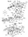
Figure 10 is an exploded view of a further embodiment of the toe-piece according to the present invention; -
Figure 11 is a view of the toe-piece according toFig. 10 , partially open; -
Figure 12 is a perspective view of the toe-piece according toFig. 10 during opening for positioning of the toe of the ski boot; -
Figure 13 is a perspective view of the toe-piece according toFig. 10 during closing onto the toe of the ski boot for use during downhill skiing; -
Figure 14 is a perspective view of the toe-piece according toFig. 10 during closing onto the toe of the ski boot for use when walking uphill; -
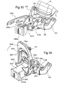
Figure 15 is a view of the toe-piece according toFig. 10 during release of the ski boot when acted on by transverse forces; and -
Figure 16 is a perspective view of the toe-piece according toFig. 10 during resetting. - As shown in
Fig. 1 and with reference to the directions shown by way of example in the figures, so that the toe-piece part furthest from the seat for thetoe 1a of the ski boot is assumed to be the "front", and a set of three axes, i.e. a longitudinal axis X-X, transverse axis Y-Y and vertical axis Z-Z, conventionally assumed for the sake of convenience of the description, the toe-piece according to the invention comprises essentially: - a
fixed base 100 formed by a first substantially flat base-piece 110 with raisedlongitudinal sides 111 having arespective eyelet 112 elongated in the longitudinal direction and arespective hole 113; the base-piece 110 is elongated in the longitudinal direction towards the front in the form of astrip 114 in which ahole 114a is present. Thebase 110 also has formed therein aninset area 110a able to contain the thickness of a counter base-piece 120 made of steel and having raisedflanges 121 in the form of a C, the arms of which parallel to the plane of thebase 110 are provided with respectivecoaxial holes 121a able to receive apin 122 forming an axis of rotation perpendicular to the plane of thebase 110; - this being intended for two
jaws 123 arranged opposite each other and symmetrical with respect to the longitudinal axis X-X and in turn formed with apower arm 123a, substantially perpendicular to thebase 110 and having a respectiveconical pin 124 extending parallel to the said base and able to engage with arespective seat 1b in thetoe 1a of the ski boot, and aresistance arm 123 substantially parallel to thebase 110; - the
fixed base 110 also has, integral therewith,resilient means 200 arranged so as to project towards the inside of the said base and acting in a direction parallel to the transverse axis Y-Y; said resilient means essentially consist of a pair ofsprings 210 supported by the respective transverse guiding and retainingelements 220 able to be displaced longitudinally inside the saideyelets 112 in the raisedsides 111 so as to vary the position of the springs in the longitudinal direction; - the free end of the two
springs 210 arranged opposite each other acts on the sides of themeans 300 for rotationally actuating thejaws 123 retaining the toe of the ski boot; said actuating means comprise alever 310 formed by a central body 311a extending in the longitudinal direction so as to be able to be arranged between the two saidsprings 210, ahead 311 shaped so as to have twocurved seats 312 symmetrical with respect to the longitudinal axis X-X and open towards the outside, as well as a through-hole 315 able to allow the insertion ofmeans 320 perpendicular to thebase 100 and forming an axis of rotation for thelever 310, as well as the element for locking displacement thereof in the two - longitudinal and transverse - directions; said axis ofrotation 320 comprises essentially a threadedpin 321, thehead 321a of which makes contact against the bottom surface of thebase 110 and theshank 321b of which passes through aneyelet 115 in the said base, an eyelet 125 in the counter base-piece 120 and enters into thesaid hole 315 of thelever 310 so as to engage with acounter-pin 322 having a female thread;
in a preferred embodiment it is envisaged that saidlever 310 is fastened by means of thepin 320 to a slidingpiece 350 having arespective hole 355 for insertion of the said pin. Thesliding piece 350 also has, formed thereon, aflange 356 in the form of an overturned L, the free arm of which is able to support a longitudinallyacting safety spring 357, the function of which will become clear below in connection with operation of the toe-piece. In its front part, the sliding piece has aneyelet 354 suitable for engagement withretaining means 354a able to prevent raising in the vertical direction Z-Z, but allow displacement of thesliding piece 350 in both senses of the longitudinal direction X-X. At the front end thesliding piece 350 has atransverse seat 355 which houses inside it: - the
transverse arm 411 of aresilient U-shaped element 410, thelongitudinal arms 412 of which haveends 412a folded towards the outside for insertion in corresponding seats 421 of alever 420 for operating the entire toe-piece, able to be rotationally operated by the user. - According to preferred embodiments, it is envisaged that said
operating lever 420 is provided with aneyelet 422 elongated in the longitudinal direction and receiving, inserted inside it, abutton 430 with agripping head 431 and fork-shaped body 432 able to be arranged over alongitudinal extension 313 of thelever 310 so as to lock/release rotation thereof. - In addition to this, it is envisaged in a preferred embodiment that the
sliding piece 350 is situated, in the vertical direction, between twostrips 340 of material with a low coefficient of friction for facilitating displacement thereof with respect to the base and rotation of the lever (311). - With the configuration described, the operating principle of the toe-piece is as follows:
- under normal conditions (
Figs. 4a, 4b ) the toe-piece has theoperating lever 420 partially raised in the clockwise direction,lever 311 kept in alignment by the twoopposite springs 210,jaws 123 withresistance arm 123b inserted in theseat 312 of the saidlever 311 and rotated outwards so as to allow entry of the toe of the ski boot in the axial direction; - once the
toe 1a of the ski boot is correctly positioned (Figs. 5a,5b ) theoperating lever 420 is rotated in the anti-clockwise direction, causing by means of the U-shaped means 420, recalling, towards the front, of thesliding piece 350 which, via thepin 320, causes displacement of thelever 311 which in turn, acting on theresistance arms 123b of thejaws 123 causes rotation thereof towards the inside with closing of the toe-piece and penetration of theconical end pins 124 inside therespective seats 1b of thetoe 1a of the ski boot; in this condition the ski boot may only rotate about the saidpins 124 if the heel-piece part (not shown) of the binding is free; - if (
Fig. 6 ) the ski boot is acted on by transverse/twisting forces - schematically indicated by the arrow F - with a high enough modulus, thepower arm 123a of thejaws 123 is acted on by a corresponding thrust which causes rotation of theresistance arm 123b which in turn rotates thelever 310 about thepin 322; At this point two different conditions may occur:- i) if the force F is not high enough to overcome the total resistance of the
transverse spring 320, the latter, reacting, will bring thejaw 123 and therefore the entire toe-piece back into the normal position, resulting in an automatic self-centring effect; - ii) if the force F is such as to overcome the total resistance of the
spring 320, the rotation of thelever 310 causes the rotation towards the outside/inside of the twojaws 123 so that the one which rotates outwards in the same direction as that of the force F is released from theseat 312 and, disengaging, allows thetoe 1a of the ski boot to come out;
- i) if the force F is not high enough to overcome the total resistance of the
- ) at this point the toe-piece is totally open and it is necessary to bring it back into the initial condition, resetting the mechanism;
- for this purpose, the
lever 420 is operated (Fig. 7a ,7b), applying a force such as to overcome the resistance of thelongitudinal safety spring 357 which hitherto had not intervened and forcing the rotation in a clockwise direction of the said lever which pushes thesliding piece 350 and therefore thelever 310 in the axial direction, causing thearm 123b of the other jaw to come out also from the respective seat and total opening thereof; - upon reaching the end-of-travel position - formed by the transverse side of the
eyelet 354 which comes into contact with thepin 354a - thelever 420 is rotated in the opposite direction so as to obtain the return movement of thesliding piece 350 towards the front of the toe-piece, said return movement causing reinsertion of theresistance arms 123b into therespective seats 312 of thelever 310 and therefore resetting of the toe-piece which is again ready for use. -
Fig. 8 shows a first variation of embodiment of the toe-piece according to the present invention, in this configuration theoperating lever 1420 being connected to theresilient U-shaped element 1410 so as to rotate in the opposite direction to that described above, namely with rotation in the anti-clockwise direction for closing of the toe-piece and rotation in the anti-clockwise direction for opening thereof. - In both cases the
lever 420 and thelever 1420 haverespective seats 420a,1420a for engaging with the end of the ski pole so that the force for closing/opening the toe-piece can be applied. -
Fig. 9 shows a further variation of embodiment of the toe-piece according to the present invention which, in this configuration, hasopposition springs 1210 arranged parallel to the longitudinal direction X-X; as shown thesprings 1210 are supported byassociated means 1220 which are fixed to thebase piece 110 and conventional per se and therefore not described in detail, the springs acting in this case against thehead part 312 of thelever 311 and the operating principle of the toe-piece remaining the same as that already described. - As shown in
Fig. 10 , a further embodiment of the toe-piece according to the present invention comprises essentially: - a
fixed base 2100 formed by a first substantially flat base-piece 2110 with raisedlongitudinal sides 2111 provided with tworespective holes base 2110 also has, incorporated therein, a counter base-piece 2120 provided with raisedflanges 121 in the form of a C, the arms of which parallel to the plane of thebase 2110 are provided with respectivecoaxial holes 121a able to receive apin 122 forming an axis of rotation perpendicular to the plane of thebase 2110; - this being intended for two
jaws 123 opposite each other and symmetrical with respect to the longitudinal axis X-X, in turn formed with apower arm 123a substantially perpendicular to thebase 2110 and provided with a respectiveconical pin 124 extending parallel to the said base and able to engage with arespective seat 1b in thetoe 1a of the ski boot, and aresistance arm 123b substantially parallel to thebase 2110; said jaws being able to rotate towards the outside through an angle greater than 90°; - means 2300 for reacting to rotation of the
jaws 123 for retaining the toe of the ski boot; said reaction means comprise acam 2311 shaped so as to have twocurved seats 2312 symmetrical with respect to the longitudinal axis X-X and open towards the outside, for allowing entry/exit of theresistance arms 123b of thejaws 123; as well as a through-hole 2315 able to allow the insertion of means 2320 perpendicular to thebase 2100 and forming an axis of rotation of thecam 2311; said axis of rotation 2320 comprises essentially apin 2321 fixed by means of pressure to thesliding piece 2350 and able to be inserted insidecorresponding holes 2355 of asliding piece 2350 inside which saidcam 2311 is inserted. - The
sliding piece 2350 is made in the form of a box open laterally so as to allow seating of thecam 2311 and a constrainingelement 2600. - Said
element 2600 has ahole 2605 extending in the transverse direction Y-Y and suitable for engagement with apin 2430a passing throughcorresponding holes 2113 in thesides 2111 of thefixed base 2100; in this way theelement 2600 forms the means for constraining thesliding piece 2350 to thefixed base 2100 with respect to which the said sliding piece is able to be displaced in both directions and the support surface for thecam 2311. - In the preferred embodiment shown, the constraining element is in the form of a "U" with
arms 2601 which have two transverse coaxial holes, one of which 2602a is a through-hole and the other one 2602b threaded, suitable for engagement with acorresponding pin 2603 having a threaded end and therefore able to exert a compressive force on thearms 2601 of the "U" for the purposes which will be described below with reference to operation of the binding. - The
transverse arm 2604 of the "U" has, projecting axially therefrom, apin 2605 able to form the support of resilient opposition means acting in the longitudinal direction X-X and consisting of aspring 2210 housed inside thesliding piece 2350 inside which it is inserted via a threadedhole 2351 which is closed by an adjustingscrew 2351a, greater or lesser screwing of which causes greater/lesser compression of the spring and therefore greater/lesser resistance to release of thejaws 123. - At its rear end the
sliding piece 2350 has asurface 2350a which is suitably shaped so as to interact with acorresponding surface 2311a of the saidcam 2311 so as to cause correct centring thereof in the rest condition. - At the front end the
sliding piece 2350 hastransverse extensions 2352 shaped in the manner of acam 2352a in the vertical direction Z-Z and able to form a stop for thefree end 2431a ofarms 2431 of alever 2430 for locking/releasing the sliding piece, able to be operated rotationally by the user about apin 2430a inserted in the transverse direction y-y inside the saidholes 2113 of theflanges 2111 of thebase piece 2110. - The toe-piece comprises, moreover, a front fork-
shaped lever 2420 pivotably mounted on thebase piece 2110 by means of an associatedtransverse pin 2420a inserted inside theholes 2114 of theflanges 2111 of thebase 2110 and the rear ends of which 2420b are able to act on thecorresponding resistance arm 123b of thejaw 123 so as to bring it from the rest (closed position) into a more open position able to allow insertion of thetoe 1a of the ski boot. - The opposing rotation outwards of the two
jaws 123 results in a displacement of thesliding piece 2350 and a compression of thelongitudinal spring 2210 which, upon release of thelever 2420, will bring the sliding piece, cam, lever and jaws back into the normal closed position. - With the configuration described, the operating principle of the toe-piece is as follows:
- in the rest condition (
Fig. 11 ) the toe-piece is normally closed and has thecontrol lever 2420 partially raised in the clockwise direction, the locking/release lever 2430 raised in the clockwise direction and thejaws 123 closed; - in order to allow entry of the
toe 1a of the ski boot in the axial direction, thecontrol lever 2420 is operated, causing it to rotate downwards (Fig. 12 ) and producing the action of the rear ends 2420b of thelever 2420 on thecorresponding arm 123b of thejaw 123 so as to bring it from the rest position into a more open position able to allow insertion of the toe of the ski boot; - once the
toe 1a of the ski boot is correctly positioned (Fig. 13 ), thecontrol lever 2420 is released and, rotating in the clockwise direction, disengages itsends 2420b from theresistance arm 123b of thejaw 123, causing the recall, towards the front, of the slidingpiece 2350 which causes the displacement of thecam 2311 which, in turn, acting on theresistance arms 123b of thejaws 123 causes rotation thereof towards the inside with closing of the toe-piece and penetration of theconical pins 124 inside therespective seats 1b in thetoe 1a of the ski boot; - once the ski boot is positioned, release of the
control lever 2420 causes the return of the toe-piece into the rest condition described above which allows the user to select two respective modes of use:- · for downhill skiing (
Fig. 13 ) with the locking/release lever 2430 raised and slidingpiece 2350 free, or - · for uphill walking (
Fig. 14 ) with the locking/release lever 2430 lowered so that theends 2431a of its arms come into contact against thecam 2352a of the slidingpiece 2350 locking it in position and preventing it from being displaced; in this condition the ski boot may only rotate about the said pins 124 if the heel-piece part (not shown) of the binding is free;
- · for downhill skiing (
- from the downhill skiing configuration shown in
Fig. 13 and if (Fig. 15 ) the ski boot is acted on by transverse/twisting forces - schematically indicated by the arrow F - with a high enough modulus, thepower arm 123a of thejaw 123 is acted on by a corresponding thrust which causes rotation of theresistance arm 123b which in turn rotates thecam 2311 on the corresponding curved seat of the constrainingelement 2600, at this point two different conditions may occur:- i) if the force F is not high enough to overcome the total resistance of the
longitudinal spring 2210, the latter, reacting, will bring the slidingpiece 2350 back into the normal position, causing an interaction between the corresponding rear shapedsurface 2350a of the said sliding piece and shapedsurface 2311a of thecam 2311 which will tend to rotate in the reverse direction, assuming the rest condition again and resulting in an automatic self-centring effect; - ii) if the force F is such as to overcome the total resistance of the
spring 2210, the rotation of thecam 2311 is such as to disengage the twoopposite centring surfaces jaws 123 so that the one which rotates outwards in the same direction as that of the force F is released from theseat 2312 and, disengaging, allows thetoe 1a of the ski boot to come out;
- i) if the force F is not high enough to overcome the total resistance of the
- ) at this point the toe-piece is totally open and it is necessary to bring it back into the initial condition, resetting the mechanism;
- for this purpose (
Fig. 16 ) thelever 2420 is operated, raising it completely in the clockwise direction; during rotation twoopposite teeth 2425 engage with the locking/release lever 2430, causing it to rotate upwards and disengaging thearms 2431 from thecams 2352a of the slidingpiece 2350; continuing its travel movement thelever 2420 enters into contact with tworeliefs 2356 of the slidingpiece 2350 which is pushed in the axial direction towards the rear, causing thearm 123b of the other jaw to come out also of the respective seat and total opening thereof; - upon reaching the end-of-travel position - determined by the total compression of the spring 2210 - the
opposite centring surfaces 2311a of the cam and 2350a of the sliding piece engage again causing the return of thecam 2311 into the normal position; rotating at this point thelever 2420 in the opposite direction, return of the slidingpiece 2350 towards the front of the toe-piece will be obtained, said return movement causing the reinsertion of theresistance arms 123b into therespective seats 2312 of thecam 2311, bringing the toe-piece back into the normal rest condition. - In order to facilitate operation of the
lever 1420, the latter has anengaging seat 1420a inside which it is possible to insert the tip of the ski pole so as to exert the thrust providing the force for opening the toe-piece.
In the event of wear of contact surfaces of the engagingpins 124 of the boot and/or theseats 1b of the latter, it will be possible to adjust thetransverse screw 2603, tightening thelongitudinal arms 2601 of the U which, adhering more firmly to the surface of thecam 2311, takes up the play, resulting in restoration of the initial operating conditions. - It can therefore be seen how, with the toe-piece according to the present invention, it is possible to obtain all the advantages resulting from the safety release mechanisms incorporated in the said toe-piece, it being also possible, however, to obtain a lower overall weight of the said heel-piece as well as simplification and reduction in the weight of the heel-piece, resulting in greater rigidity of the binding and therefore improved manoeuvrability of the ski.
- In addition to this, it can also be seen how it is possible to adjust easily the resistance to opening of the toe-piece by displacing, in the longitudinal direction, the position of the
springs 210 inside theeyelet 112 of thebase 110, this allowing the production of a single toe-piece model able to operate correctly for a wider range (weight) of users. - Moreover, the toe-piece according to the invention allows easy adjustment depending on the variation in transverse width of the seats engaging with the ski boot, said width diminishing with the wear of the said seats, as well as a practical fitting action obtained by means of the thrusting force applied on the
lever 2420 by the tip of the ski pole, resulting in widening of the jaws, allowing insertion of the toe of the ski boot.
Claims (37)
- Toe-piece for ski bindings comprising a. fixed support base (100;2100) having two jaws (123) situated opposite each other and with a respective pin (124) extending towards the inside in the transverse direction (Y-Y) and able to engage with a respective seat (1b) in the toe (1a) of a ski boot, said jaws (123) being able to rotate about an axis (122) substantially perpendicular to the support base (100;2100) from a closed position into an open position and vice versa for locking/releasing the toe (1a) of a ski boot, said jaws having a resistance arm (123b) co-operating with reaction means (311;2311) able to rotate about an axis (320;2320) perpendicular to the base (100;2100) against the opposing action of resilient means (210;1210;2210) integral with the said toe-piece, characterized in that said reaction means (311;2311) are constrained to a sliding piece (350;2350) able to be displaced in both senses in the longitudinal direction (X-X) against the recall action of resilient means (357;2210) and in that the respective pin (124) is conical.
- Toe-piece according to Claim 1, characterized in that said fixed base (2100) comprises a first substantially flat base-piece (2110) with raised longitudinal sides (2111) having two respective holes (2113,2114) coaxial with each other and arranged at different heights from the plane in the direction (Z-Z).
- Toe-piece according to Claim 2, characterized in that the base (2110) has, incorporated therein, a counter base-piece (2120) provided with raised flanges (121) in the form of a C, the arms of which parallel to the plane of the base (2110) are provided with respective coaxial holes (121a) able to receive a pin (122) forming an axis of rotation perpendicular to the plane of the base (2110).
- Toe-piece according to Claim 3, characterized in said jaws (123) are pivotably mounted on said axis of rotation (122) perpendicular to the plane of the base (2110).
- Toe-piece according to Claim 3, characterized in that said jaws (123) are situated opposite each other and symmetrical with respect to the longitudinal axis (X-X) and comprise a power arm (123a) substantially perpendicular to the base (110; 2110) and provided with said conical pin (124) extending parallel to the said base and a resistance arm (123b) substantially parallel to the base (110;2110).
- Toe-piece according to Claim 1, characterized in that said reaction means comprise a cam (2311) shaped so as to have two curved seats (2312) symmetrical with respect to the longitudinal axis (X-X) and open towards the outside so as to allow entry/exit of the resistance arms (123b) of the jaws (123) as well as a through-hole (2315) able to allow the insertion of means (2320) perpendicular to the base (2100) and forming an axis of rotation of the cam (2311).
- Toe-piece according to Claim 1, characterized in that the sliding piece (2350) is made in the form of a box open laterally so as to be able to receive the cam (2311) and an element (2600) for performing constraining to the base (2100).
- Toe-piece according to Claim 1, characterized in that said sliding piece (2350) has, on its front surface, a threaded hole (2351) closed by an adjusting screw (2351a).
- Toe-piece according to Claim 1, characterized in that said resilient opposition means acting in the longitudinal direction X-X are housed inside said sliding piece.
- Toe-piece according to Claim 9, characterized in that said resilient opposition means comprise a spring (2210) longitudinally situated between said adjusting screw (2351a) and a pin (2605) axially projecting from said constraining means (2600).
- Toe-piece according to Claim 1, characterized in that said sliding piece (2350) has at its rear end a surface (2350a) suitably shaped so as to interact with a corresponding surface (2311a) of the said cam (2311) so as to cause correct centring thereof.
- Toe-piece according to Claim 1, characterized in that the sliding piece (2350) has at its front end transverse extensions (2352) shaped as a cam (2352a) in the vertical direction (Z-Z) and able to form a stop for the free end (2431a) of arms (2431) of a lever (2430) for locking/unlocking the sliding piece.
- Toe-piece according to Claim 12, characterized in that said locking/unlocking lever (2430) is able to rotate about a pin (2430a) inserted in the transverse direction (Y-Y) of holes (2113) in the flanges (2111) of the base piece (2110).
- Toe-piece according to Claim 7, characterized in that said element for constraining the sliding piece (2350) to the base (2110) is in the form of a U witch arms (2601) extending in the longitudinal direction (X-X) and provided with transverse coaxial holes, one of which (2602a) is a through-hole and the other (2602b) a threaded hole, suitable for engagement with a corresponding pin (2603) having a threaded end.
- Toe-piece according to Claim 1, characterized in that it comprises a front lever (2420) in the form of a fork pivotably mounted on the base piece (2110) by means of an associated transverse pin (2420a) inserted in the holes (2114) in the flanges (2111) of the base (2110), the rear ends (2420b) of said lever being able to act on the corresponding resistance arm (123b) of the jaw (123) so as to bring it from the rest position into a more open position able to allow insertion of the toe (1a) of the ski boot.
- Toe-piece according to Claim 1, characterized in that said base (100) comprises a first base piece (110) associated with a counter base-piece (120) provided with flanges (121) able to receive a pin (122) forming an axis of rotation perpendicular to the plane of the base (110) for said jaws (123).
- Toe-piece according to Claim 16, characterized in that said flanges (121) are raised in the form of a C and the arms parallel to the plane of the base (110) are provided with the respective coaxial holes (121a) for receiving said pin (122).
- Toe-piece according to Claim 16, characterized in that said base piece (110) has raised longitudinal sides (111) perpendicular to the said base and provided with a respective eyelet (112) extending in the longitudinal direction (X-X).
- Toe-piece according to Claim 16, characterized in that said first base piece (110) comprises a strip (114) elongated in the longitudinal direction towards the front and provided with a hole (114a) able to engage with a corresponding locking pin (354a) in the vertical direction (Z-Z).
- Toe-piece according to Claim 1, characterized in that said means for actuating the jaws (123) comprise a lever (310) formed by a central body (311a) extending in the longitudinal direction and a head (311) shaped so as to have two curved seats (312) symmetrical with respect to the longitudinal axis (X-X) and open towards the outside.
- Toe-piece according to Claim 20, characterized in that said lever (311) has a through-hole (315) able to allow the insertion of means (320) perpendicular to the base (100) and forming an axis of rotation of the lever (310).
- Toe-piece according to Claim 21, characterized in that said axis of rotation (320) essentially consists of a threaded pin (321), the head (321a) of which comes into contact against the bottom surface of the base (110) and the shank (321b) of which passes through an eyelet (115) in the said base, an eyelet (125) in the counter base-piece (120) and enters into said hole (315) of the lever (310) so as to engage with a counter-pin (322) having a female thread.
- Toe-piece according to Claim 1, characterized in that said sliding piece (350) has, at the front thereof, an eyelet (354) receiving retaining means (354a) able to prevent raising of the sliding piece in the vertical direction (Z-Z) and allow displacement thereof in both senses in the longitudinal direction (X-X).
- Toe-piece according to Claim 1, characterized in that said sliding piece (350) has a flange (356) in the form of an overturned L, the free arm of which is able to support resilient safety means (357) acting in the longitudinal direction (X-X) against the action of the said control means (420).
- Toe-piece according to Claim 1, characterized in that, at its front end, said sliding piece (350) has a transverse seat (355) able to engage with said control means (410, 420).
- Toe-piece according to Claim 1, characterized in that said sliding piece (350) is situated, in the vertical direction, between two strips (340) of material with a low coefficient of friction.
- Toe-piece according to Claim 1, characterized in that said resilient means (200) comprise a pair of springs (210) extending in the transverse direction and situated opposite each other, the free end thereof acting on the sides of the means (300) for actuating the jaws (123).
- Toe-piece according to Claim 27, characterized in the said resilient means (210) are supported by respective transverse guiding and retaining elements (220), integral with the sides (111) of the base (110).
- Toe-piece according to Claim 28, characterized in said means (220) supporting the springs (210) are able to be displaced in the longitudinal direction inside the said eyelets (112) of the raised sides (111) so as to vary the point of application of the transverse opposing action of the springs.
- Toe-piece according to Claim 1, characterized in that said resilient means (1200) comprise a pair of springs (1210) arranged parallel to the longitudinal direction (X-X) on opposite sides of the lever (311) and acting against the head part (312) of the said lever.
- Toe-piece according to Claim 30, characterized in that said springs (1210) are supported by associated means (1220) fixed to the base piece (110).
- Toe-piece according to Claim 1, characterized in that said control means (410,420;1410) comprise a resilient element (410) in the form of a U, the longitudinal arms (412) of which have ends (412a) folded towards the outside for insertion in corresponding seats (421;1421) of a lever (420;1420) for operating the entire toe-piece, able to be rotationally operated by the user.
- Toe-piece according to Claim 32, characterized in that the transverse arm (411) of the said resilient element is suitable for insertion inside a front transverse seat (355) of the sliding piece (350).
- Toe-piece according to Claim 1, characterized in that said operating lever (420) is provided with an eyelet (422) elongated in the longitudinal direction and able to form a seat for a button (430) displaceable in both senses of the longitudinal direction inside said eyelet so as to cause locking/unlocking of the rotational movement of the lever (310) actuating the jaws (123).
- Toe-piece according to Claim 1, characterized in that said button (430) has a gripping head (431) and fork-shaped body (432) able to be arranged over a longitudinal extension (313) thereof.
- Toe-piece according to Claim 1, characterized in that the lever (420;1420;2420) has at least one respective seat (420a,1420a;2420a) for engagement with the tip of a ski pole.
- Toe-piece according to Claim 1, characterized in that the outwards rotation of said jaws (123) may extend through an angle greater than 90°.
Applications Claiming Priority (2)
| Application Number | Priority Date | Filing Date | Title |
|---|---|---|---|
| IT001429A ITMI20051429A1 (en) | 2005-07-22 | 2005-07-22 | TIP FOR SKI ATTACHMENTS |
| PCT/IB2006/002131 WO2007010392A2 (en) | 2005-07-22 | 2006-07-20 | Toe-piece for ski bindings |
Publications (2)
| Publication Number | Publication Date |
|---|---|
| EP1907078A2 EP1907078A2 (en) | 2008-04-09 |
| EP1907078B1 true EP1907078B1 (en) | 2009-10-07 |
Family
ID=37589182
Family Applications (1)
| Application Number | Title | Priority Date | Filing Date |
|---|---|---|---|
| EP06779929A Not-in-force EP1907078B1 (en) | 2005-07-22 | 2006-07-20 | Toe-piece for ski bindings |
Country Status (5)
| Country | Link |
|---|---|
| EP (1) | EP1907078B1 (en) |
| AT (1) | ATE444788T1 (en) |
| DE (1) | DE602006009660D1 (en) |
| IT (1) | ITMI20051429A1 (en) |
| WO (1) | WO2007010392A2 (en) |
Families Citing this family (28)
| Publication number | Priority date | Publication date | Assignee | Title |
|---|---|---|---|---|
| EP3300778B1 (en) | 2008-04-03 | 2020-05-06 | G3 Genuine Guide Gear Inc. | Toe unit for alpine touring binding |
| EP2243388B1 (en) | 2009-04-08 | 2011-10-05 | Ski Trab S.r.l. | Ski-boot with means for actuating corresponding engaging members of ski-touring bindings |
| IT1396278B1 (en) * | 2009-04-15 | 2012-11-16 | Rigat | TIP OF A SKI ATTACK |
| IT1396339B1 (en) * | 2009-10-06 | 2012-11-16 | Roberto Giordani | TIP OF LOCKED MOUNTABLE SKI ATTACKS |
| EP2319595B1 (en) * | 2009-11-04 | 2014-08-13 | Salewa Sport AG | Cross-country ski binding with a base plate comprising a fixing hole assembly and base plate |
| IT1397694B1 (en) * | 2010-01-22 | 2013-01-24 | Atk Race Srl | TIP FOR SKI-MOUNTAIN ATTACKS. |
| DE102010001603A1 (en) * | 2010-02-04 | 2011-08-04 | Salewa Sport Ag | Touring ski binding with locking mechanism |
| ITTO20110075A1 (en) * | 2011-01-31 | 2012-08-01 | Marco Rigat | SECURITY TIP FOR MOUNTAIN SKI ATTACK. |
| DE102010043879A1 (en) * | 2010-11-12 | 2012-05-16 | Salewa Sport Ag | Touring binding with release mechanism and locking mechanism |
| FR2972642B1 (en) * | 2011-03-18 | 2017-03-17 | Felisaz Sas Fixations Plum | SPRING LATCH- LOCKED / UNLOCKED POSITION SELECTOR FOR SKI-ALPINISM FASTENING |
| CH705579A2 (en) | 2011-09-29 | 2013-04-15 | Fritschi Ag Swiss Bindings | Front machine. |
| DE202011109616U1 (en) * | 2011-12-28 | 2012-02-06 | Sepp Heumann | Safety binding system |
| DE102012207959B4 (en) * | 2012-05-11 | 2020-11-12 | Fritz Barthel | Front unit of a gliding board binding and gliding board binding |
| FR2991592B1 (en) * | 2012-06-12 | 2016-08-26 | Rossignol Sa | TORSIONALLY AUTOMATIC TRIGGER STOP |
| FR3002460B1 (en) * | 2013-02-22 | 2017-08-25 | Rossignol Sa | TORSIONALLY AUTOMATIC TRIGGER STOP |
| DE102013003839A1 (en) * | 2013-03-07 | 2014-09-11 | Reinhold Zoor | Pin toe with horizontally mounted release jaws |
| DE102013204060B4 (en) * | 2013-03-08 | 2015-01-22 | Micado Cad-Solutions Gmbh | Toe bows for a ski touring binding |
| EP2946817B1 (en) * | 2014-05-19 | 2017-05-03 | Ski Trab S.r.l. | Toe-piece for ski-touring bindings |
| ITUB20153027A1 (en) | 2015-08-10 | 2017-02-10 | Scarpa Calzaturificio Spa | SKI BOOT |
| FR3046083B1 (en) * | 2015-12-23 | 2018-01-12 | Salomon Sas | SKI FIXING |
| EP3266504A1 (en) * | 2016-07-07 | 2018-01-10 | Fritschi AG - Swiss Bindings | Ski binding |
| FR3072884B1 (en) * | 2017-11-02 | 2022-01-21 | Rossignol Sa | SHOE FIXING DEVICE STOP |
| SK8337Y1 (en) | 2018-02-20 | 2019-01-08 | Gaborik Jozef | Front unit of a ski binding |
| IT201800009744A1 (en) | 2018-10-24 | 2020-04-24 | Atk Race Srl | SKI ATTACHMENT TOE |
| FR3097773B1 (en) | 2019-06-26 | 2022-01-21 | Rossignol Sa | Front stopper for ski touring bindings |
| IT201900013143A1 (en) * | 2019-07-29 | 2021-01-29 | Atk Sports S R L | SKI ATTACHMENT TOE FOR SKI MOUNTAINEERING |
| DE102021101355A1 (en) * | 2021-01-22 | 2022-07-28 | Salewa Sport Ag | GLIDEBOARD BINDING WITH HOUSING BOLTED IN HORIZONTAL DIRECTION |
| IT202100012872A1 (en) * | 2021-05-19 | 2022-11-19 | Atk Sports S R L | REAR PORTION OF A SKI MOUNTAINEERING BINDING |
Family Cites Families (2)
| Publication number | Priority date | Publication date | Assignee | Title |
|---|---|---|---|---|
| US4348036A (en) * | 1980-08-19 | 1982-09-07 | Settembre Richard J | Safety binding for nordic skis |
| AT381458B (en) * | 1985-03-25 | 1986-10-27 | Barthel Fritz | TOURING SKI BINDING |
-
2005
- 2005-07-22 IT IT001429A patent/ITMI20051429A1/en unknown
-
2006
- 2006-07-20 DE DE602006009660T patent/DE602006009660D1/en active Active
- 2006-07-20 AT AT06779929T patent/ATE444788T1/en active
- 2006-07-20 EP EP06779929A patent/EP1907078B1/en not_active Not-in-force
- 2006-07-20 WO PCT/IB2006/002131 patent/WO2007010392A2/en not_active Application Discontinuation
Also Published As
| Publication number | Publication date |
|---|---|
| DE602006009660D1 (en) | 2009-11-19 |
| EP1907078A2 (en) | 2008-04-09 |
| WO2007010392A3 (en) | 2007-04-05 |
| ATE444788T1 (en) | 2009-10-15 |
| ITMI20051429A1 (en) | 2007-01-23 |
| WO2007010392A2 (en) | 2007-01-25 |
Similar Documents
| Publication | Publication Date | Title |
|---|---|---|
| EP1907078B1 (en) | Toe-piece for ski bindings | |
| EP2281614B1 (en) | Heel piece with two-armed front fork engageable with pins on a boot | |
| EP3300778B1 (en) | Toe unit for alpine touring binding | |
| US20130181427A1 (en) | Touring heel binding having a dynamic sliding region | |
| US9440137B2 (en) | Toe-piece for ski-touring bindings | |
| US20160089592A1 (en) | Heel-piece for binding a boot on a gliding board | |
| EP2243388B1 (en) | Ski-boot with means for actuating corresponding engaging members of ski-touring bindings | |
| EP2707110B1 (en) | Ski binding for fastening a mountaineering boot on a downhill ski or the like | |
| US4421341A (en) | Safety ski binding | |
| US7909352B2 (en) | Article including a button which is movable between at least two positions | |
| WO2009153615A1 (en) | Multi-position heel piece for ski mountaineering bindings | |
| WO1980001141A1 (en) | A step-in ski binding | |
| US20040056449A1 (en) | Binding device with front unfastening | |
| US6390494B2 (en) | Cross-country ski binding | |
| US5265901A (en) | Heel unit for ski bindings with automatic reset means | |
| EP2707111B1 (en) | Ski binding device for fastening a mountaineering boot on a downhill ski or the like | |
| EP1602296B1 (en) | Ratchet device particularly for sports shoes | |
| EP0448009B1 (en) | Safety ski binding | |
| US4607859A (en) | Safety ski binding | |
| US11524220B2 (en) | Ski binding | |
| US6412808B1 (en) | Boot/ski safety binding | |
| US4624475A (en) | Release ski binding | |
| US4573701A (en) | Release ski binding | |
| JPS5836988B2 (en) | Kaihoji Zainoski Binding | |
| EP0457263A1 (en) | Safety ski binding |
Legal Events
| Date | Code | Title | Description |
|---|---|---|---|
| PUAI | Public reference made under article 153(3) epc to a published international application that has entered the european phase |
Free format text: ORIGINAL CODE: 0009012 |
|
| AK | Designated contracting states |
Kind code of ref document: A2 Designated state(s): AT CH DE FR IT LI |
|
| 17P | Request for examination filed |
Effective date: 20080109 |
|
| RBV | Designated contracting states (corrected) |
Designated state(s): AT CH DE FR IT LI |
|
| GRAP | Despatch of communication of intention to grant a patent |
Free format text: ORIGINAL CODE: EPIDOSNIGR1 |
|
| DAX | Request for extension of the european patent (deleted) | ||
| GRAS | Grant fee paid |
Free format text: ORIGINAL CODE: EPIDOSNIGR3 |
|
| GRAA | (expected) grant |
Free format text: ORIGINAL CODE: 0009210 |
|
| AK | Designated contracting states |
Kind code of ref document: B1 Designated state(s): AT CH DE FR IT LI |
|
| REG | Reference to a national code |
Ref country code: CH Ref legal event code: EP |
|
| REF | Corresponds to: |
Ref document number: 602006009660 Country of ref document: DE Date of ref document: 20091119 Kind code of ref document: P |
|
| REG | Reference to a national code |
Ref country code: CH Ref legal event code: NV Representative=s name: DR. LUSUARDI AG |
|
| PLBE | No opposition filed within time limit |
Free format text: ORIGINAL CODE: 0009261 |
|
| STAA | Information on the status of an ep patent application or granted ep patent |
Free format text: STATUS: NO OPPOSITION FILED WITHIN TIME LIMIT |
|
| 26N | No opposition filed |
Effective date: 20100708 |
|
| PG25 | Lapsed in a contracting state [announced via postgrant information from national office to epo] |
Ref country code: IT Free format text: LAPSE BECAUSE OF FAILURE TO SUBMIT A TRANSLATION OF THE DESCRIPTION OR TO PAY THE FEE WITHIN THE PRESCRIBED TIME-LIMIT Effective date: 20091007 |
|
| REG | Reference to a national code |
Ref country code: FR Ref legal event code: PLFP Year of fee payment: 11 |
|
| PGFP | Annual fee paid to national office [announced via postgrant information from national office to epo] |
Ref country code: CH Payment date: 20160714 Year of fee payment: 11 |
|
| PGFP | Annual fee paid to national office [announced via postgrant information from national office to epo] |
Ref country code: DE Payment date: 20160929 Year of fee payment: 11 |
|
| REG | Reference to a national code |
Ref country code: FR Ref legal event code: PLFP Year of fee payment: 12 |
|
| REG | Reference to a national code |
Ref country code: DE Ref legal event code: R082 Ref document number: 602006009660 Country of ref document: DE |
|
| REG | Reference to a national code |
Ref country code: DE Ref legal event code: R119 Ref document number: 602006009660 Country of ref document: DE |
|
| REG | Reference to a national code |
Ref country code: CH Ref legal event code: PL |
|
| PG25 | Lapsed in a contracting state [announced via postgrant information from national office to epo] |
Ref country code: DE Free format text: LAPSE BECAUSE OF NON-PAYMENT OF DUE FEES Effective date: 20180201 Ref country code: CH Free format text: LAPSE BECAUSE OF NON-PAYMENT OF DUE FEES Effective date: 20170731 Ref country code: LI Free format text: LAPSE BECAUSE OF NON-PAYMENT OF DUE FEES Effective date: 20170731 |
|
| REG | Reference to a national code |
Ref country code: FR Ref legal event code: PLFP Year of fee payment: 13 |
|
| PGFP | Annual fee paid to national office [announced via postgrant information from national office to epo] |
Ref country code: FR Payment date: 20190725 Year of fee payment: 14 |
|
| PGFP | Annual fee paid to national office [announced via postgrant information from national office to epo] |
Ref country code: AT Payment date: 20190718 Year of fee payment: 14 |
|
| REG | Reference to a national code |
Ref country code: AT Ref legal event code: MM01 Ref document number: 444788 Country of ref document: AT Kind code of ref document: T Effective date: 20200720 |
|
| PG25 | Lapsed in a contracting state [announced via postgrant information from national office to epo] |
Ref country code: FR Free format text: LAPSE BECAUSE OF NON-PAYMENT OF DUE FEES Effective date: 20200731 |
|
| PG25 | Lapsed in a contracting state [announced via postgrant information from national office to epo] |
Ref country code: AT Free format text: LAPSE BECAUSE OF NON-PAYMENT OF DUE FEES Effective date: 20200720 |