EP2946482B1 - Verfahren und vorrichtung zur auflösung von mehrdeutiger kapazitätssignalisierung eines benutzergeräts - Google Patents
Verfahren und vorrichtung zur auflösung von mehrdeutiger kapazitätssignalisierung eines benutzergeräts Download PDFInfo
- Publication number
- EP2946482B1 EP2946482B1 EP13802188.6A EP13802188A EP2946482B1 EP 2946482 B1 EP2946482 B1 EP 2946482B1 EP 13802188 A EP13802188 A EP 13802188A EP 2946482 B1 EP2946482 B1 EP 2946482B1
- Authority
- EP
- European Patent Office
- Prior art keywords
- combination
- capabilities
- mimo
- comp
- band
- Prior art date
- Legal status (The legal status is an assumption and is not a legal conclusion. Google has not performed a legal analysis and makes no representation as to the accuracy of the status listed.)
- Active
Links
- 238000000034 method Methods 0.000 title claims description 64
- 230000011664 signaling Effects 0.000 title claims description 34
- 238000004891 communication Methods 0.000 claims description 38
- 230000002776 aggregation Effects 0.000 claims description 8
- 238000004220 aggregation Methods 0.000 claims description 8
- 238000004590 computer program Methods 0.000 claims description 4
- 230000008569 process Effects 0.000 description 19
- 230000005540 biological transmission Effects 0.000 description 12
- 238000005516 engineering process Methods 0.000 description 7
- 230000015654 memory Effects 0.000 description 7
- 230000006870 function Effects 0.000 description 6
- 238000005259 measurement Methods 0.000 description 5
- 238000012545 processing Methods 0.000 description 5
- 238000010586 diagram Methods 0.000 description 4
- 125000004122 cyclic group Chemical group 0.000 description 3
- 230000007774 longterm Effects 0.000 description 3
- 230000001413 cellular effect Effects 0.000 description 2
- 230000001419 dependent effect Effects 0.000 description 2
- 239000000835 fiber Substances 0.000 description 2
- 239000011159 matrix material Substances 0.000 description 2
- 230000003287 optical effect Effects 0.000 description 2
- 230000008520 organization Effects 0.000 description 2
- 230000002441 reversible effect Effects 0.000 description 2
- 230000006399 behavior Effects 0.000 description 1
- 239000000969 carrier Substances 0.000 description 1
- 230000000295 complement effect Effects 0.000 description 1
- 230000008878 coupling Effects 0.000 description 1
- 238000010168 coupling process Methods 0.000 description 1
- 238000005859 coupling reaction Methods 0.000 description 1
- 238000013461 design Methods 0.000 description 1
- 238000001514 detection method Methods 0.000 description 1
- 230000002452 interceptive effect Effects 0.000 description 1
- 238000010295 mobile communication Methods 0.000 description 1
- 238000012986 modification Methods 0.000 description 1
- 230000004048 modification Effects 0.000 description 1
- 239000005022 packaging material Substances 0.000 description 1
- 230000001360 synchronised effect Effects 0.000 description 1
- 238000012546 transfer Methods 0.000 description 1
- 238000011144 upstream manufacturing Methods 0.000 description 1
Images


Classifications
-
- H—ELECTRICITY
- H04—ELECTRIC COMMUNICATION TECHNIQUE
- H04W—WIRELESS COMMUNICATION NETWORKS
- H04W8/00—Network data management
- H04W8/22—Processing or transfer of terminal data, e.g. status or physical capabilities
- H04W8/24—Transfer of terminal data
-
- H—ELECTRICITY
- H04—ELECTRIC COMMUNICATION TECHNIQUE
- H04B—TRANSMISSION
- H04B7/00—Radio transmission systems, i.e. using radiation field
- H04B7/02—Diversity systems; Multi-antenna system, i.e. transmission or reception using multiple antennas
- H04B7/022—Site diversity; Macro-diversity
- H04B7/024—Co-operative use of antennas of several sites, e.g. in co-ordinated multipoint or co-operative multiple-input multiple-output [MIMO] systems
-
- H—ELECTRICITY
- H04—ELECTRIC COMMUNICATION TECHNIQUE
- H04B—TRANSMISSION
- H04B7/00—Radio transmission systems, i.e. using radiation field
- H04B7/02—Diversity systems; Multi-antenna system, i.e. transmission or reception using multiple antennas
- H04B7/04—Diversity systems; Multi-antenna system, i.e. transmission or reception using multiple antennas using two or more spaced independent antennas
- H04B7/0413—MIMO systems
-
- H—ELECTRICITY
- H04—ELECTRIC COMMUNICATION TECHNIQUE
- H04B—TRANSMISSION
- H04B7/00—Radio transmission systems, i.e. using radiation field
- H04B7/02—Diversity systems; Multi-antenna system, i.e. transmission or reception using multiple antennas
- H04B7/04—Diversity systems; Multi-antenna system, i.e. transmission or reception using multiple antennas using two or more spaced independent antennas
- H04B7/06—Diversity systems; Multi-antenna system, i.e. transmission or reception using multiple antennas using two or more spaced independent antennas at the transmitting station
- H04B7/0613—Diversity systems; Multi-antenna system, i.e. transmission or reception using multiple antennas using two or more spaced independent antennas at the transmitting station using simultaneous transmission
- H04B7/0615—Diversity systems; Multi-antenna system, i.e. transmission or reception using multiple antennas using two or more spaced independent antennas at the transmitting station using simultaneous transmission of weighted versions of same signal
- H04B7/0619—Diversity systems; Multi-antenna system, i.e. transmission or reception using multiple antennas using two or more spaced independent antennas at the transmitting station using simultaneous transmission of weighted versions of same signal using feedback from receiving side
- H04B7/0621—Feedback content
- H04B7/0628—Diversity capabilities
-
- H—ELECTRICITY
- H04—ELECTRIC COMMUNICATION TECHNIQUE
- H04W—WIRELESS COMMUNICATION NETWORKS
- H04W8/00—Network data management
- H04W8/22—Processing or transfer of terminal data, e.g. status or physical capabilities
Definitions
- Certain aspects of the present disclosure generally relate to wireless communications and, more particularly, to resolving ambiguous user equipment (UE) capability signaling.
- UE user equipment
- Wireless communication systems are widely deployed to provide various types of communication content such as voice, data, and so on. These systems may be multiple-access systems capable of supporting communication with multiple users by sharing the available system resources (e.g., bandwidth and transmit power). Examples of such multiple-access systems include code division multiple access (CDMA) systems, time division multiple access (TDMA) systems, frequency division multiple access (FDMA) systems, 3rd Generation Partnership Project (3GPP) Long Term Evolution (LTE)/LTE-Advanced systems and orthogonal frequency division multiple access (OFDMA) systems.
- CDMA code division multiple access
- TDMA time division multiple access
- FDMA frequency division multiple access
- 3GPP 3rd Generation Partnership Project
- LTE Long Term Evolution
- LTE-Advanced systems orthogonal frequency division multiple access
- a wireless multiple-access communication system can simultaneously support communication for multiple wireless terminals.
- Each terminal communicates with one or more base stations via transmissions on the forward and reverse links.
- the forward link (or downlink) refers to the communication link from the base stations to the terminals
- the reverse link (or uplink) refers to the communication link from the terminals to the base stations.
- This communication link may be established via a single-input single-output, multiple-input single-output or a multiple-input multiple-output (MIMO) system.
- MIMO multiple-input multiple-output
- a wireless communication network may include a number of base stations that can support communication for a number of wireless devices.
- Wireless devices comprise user equipments (UEs) and remote devices.
- UE user equipments
- a UE is a device that operates under direct control by humans. Some examples of UEs include cellular phones, smart phones, personal digital assistants (PDAs), wireless modems, handheld devices, tablets, laptop computers, netbooks, smartbooks, ultrabooks, etc.
- a remote device is a device that operates without being directly controlled by humans. Some examples of remote devices include sensors, meters, location tags, etc.
- a remote device may communicate with a base station, another remote device, or some other entity.
- Machine type communication refers to communication involving at least one remote device on at least one end of the communication.
- Document WO 2012/141634 A1 discloses a method in a base station for communicating with a user equipment in a communication network.
- the base station is configured to communicate with the user equipment according to a selectable of at least two user equipment categories. Based on information about a selected user equipment category, the base station determines a first number of maximum transmission layers supported by the base station. The base station communicates with the user equipment according to up to the determined first number of maximum transmission layers and according to the selected user equipment category.
- Certain aspects of the present disclosure provide a method for wireless communications by a user equipment (UE).
- the method generally includes determining capabilities of the UE to support at least one of multiple-input multiple-output (MIMO) or coordinated multipoint (CoMP) features on different operating frequency bands of a radio access network (RAN), signaling, to a base station (BS) of the RAN, a first combination of capabilities of the UE for a combination of bands, signaling, to the BS, a second combination of capabilities, different than the first combination of capabilities, for the combination of bands, and identifying, based on one or more criteria, a particular combination of capabilities to be used to communicate with the BS.
- MIMO multiple-input multiple-output
- CoMP coordinated multipoint
- Certain aspects of the present disclosure provide a method for wireless communications by a base station (BS).
- the method generally includes receiving, from a user equipment (UE), signaling indicating a first combination of capabilities of the UE to support at least one of multiple-input multiple-output (MIMO) or coordinated multipoint (CoMP) features on different operating frequency bands of a radio access network (RAN) for a combination of bands, receiving, from the UE, signaling indicating a second combination of capabilities of the UE to support at least one of MIMO or CoMP features on different operating frequency bands of a RAN, different than the first combination of capabilities, for the combination of bands, and identifying, based on one or more criteria, a particular combination of capabilities to be used to communicate with the UE.
- MIMO multiple-input multiple-output
- CoMP coordinated multipoint
- Certain aspects also provide various apparatuses and program products for performing operations of the methods above.
- Certain aspects of the present disclosure generally relate to resolving ambiguous user equipment (UE) capability signaling.
- Ambiguous signaling may results when the UE signals to a base station (BS) a first combination of UE capabilities for a combination of bands and also signals a second, different, combination of capabilities for the same combination of bands.
- BS base station
- a particular combination of capabilities to be used to communicate with the BS may be identified by applying a deterministic rule to determine which combination of capabilities to use. For example, using the first signaled combination or a first alphabetically ordered combination.
- the network may signal a combination of capabilities to be used. The combination may be different than either of the combination signaled by the UE.
- a CDMA network may implement a radio technology such as universal terrestrial radio access (UTRA), cdma2000, etc.
- UTRA includes wideband CDMA (WCDMA), time division synchronous CDMA (TD-SCDMA), and other variants of CDMA.
- cdma2000 covers IS-2000, IS-95 and IS-856 standards.
- a TDMA network may implement a radio technology such as global system for mobile communications (GSM).
- GSM global system for mobile communications
- An OFDMA network may implement a radio technology such as evolved UTRA (E-UTRA), ultra mobile broadband (UMB), IEEE 802.11 (Wi-Fi), IEEE 802.16 (WiMAX), IEEE 802.20, Flash-OFDM, etc.
- E-UTRA evolved UTRA
- UMB ultra mobile broadband
- IEEE 802.11 Wi-Fi
- WiMAX IEEE 802.16
- Flash-OFDM Flash-OFDM
- UTRA and E-UTRA are part of universal mobile telecommunication system (UMTS).
- 3GPP Long Term Evolution (LTE) and LTE-Advanced (LTE-A), in both frequency division duplex (FDD) and time division duplex (TDD), are new releases of UMTS that use E-UTRA, which employs OFDMA on the downlink and SC-FDMA on the uplink.
- LTE Long Term Evolution
- LTE-A LTE-Advanced
- FDD frequency division duplex
- TDD time division duplex
- UTRA, E-UTRA, UMTS, LTE, LTE-A and GSM are described in documents from an organization named "3rd Generation Partnership Project” (3GPP).
- cdma2000 and UMB are described in documents from an organization named “3rd Generation Partnership Project 2" (3GPP2).
- the techniques described herein may be used for the wireless networks and radio technologies mentioned above as well as other wireless networks and radio technologies. For clarity, certain aspects of the techniques are described below for LTE/LTE-Advanced, and LTE/LTE-Advanced terminology is used in much of the description below.
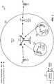
- FIG. 1 shows a wireless communication network 100, which may be an LTE network or some other wireless network.
- Wireless network 100 may include a number of evolved Node Bs (eNBs) 110 and other network entities.
- An eNB is an entity that communicates with user equipments (UEs) and may also be referred to as a base station, a Node B, an access point, etc.
- UEs user equipments
- Each eNB may provide communication coverage for a particular geographic area.
- the term "cell" can refer to a coverage area of an eNB and/or an eNB subsystem serving this coverage area, depending on the context in which the term is used.
- An eNB may provide communication coverage for a macro cell, a pico cell, a femto cell, and/or other types of cell.
- a macro cell may cover a relatively large geographic area (e.g., several kilometers in radius) and may allow unrestricted access by UEs with service subscription.
- a pico cell may cover a relatively small geographic area and may allow unrestricted access by UEs with service subscription.
- a femto cell may cover a relatively small geographic area (e.g., a home) and may allow restricted access by UEs having association with the femto cell (e.g., UEs in a closed subscriber group (CSG)).
- An eNB for a macro cell may be referred to as a macro eNB.
- An eNB for a pico cell may be referred to as a pico eNB.
- An eNB for a femto cell may be referred to as a femto eNB or a home eNB (HeNB).
- HeNB home eNB
- an eNB 110a may be a macro eNB for a macro cell 102a
- an eNB 110b may be a pico eNB for a pico cell 102b
- an eNB 110c may be a femto eNB for a femto cell 102c.
- An eNB may support one or multiple (e.g., three) cells.
- the terms "eNB", “base station” and “cell” may be used interchangeably herein.
- Wireless network 100 may also include relay stations.
- a relay station is an entity that can receive a transmission of data from an upstream station (e.g., an eNB or a UE) and send a transmission of the data to a downstream station (e.g., a UE or an eNB).
- a relay station may also be a UE that can relay transmissions for other UEs.
- a relay station 110d may communicate with macro eNB 110a and a UE 120d in order to facilitate communication between eNB 110a and UE 120d.
- a relay station may also be referred to as a relay eNB, a relay base station, a relay, etc.
- Wireless network 100 may be a heterogeneous network that includes eNBs of different types, e.g., macro eNBs, pico eNBs, femto eNBs, relay eNBs, etc. These different types of eNBs may have different transmit power levels, different coverage areas, and different impact on interference in wireless network 100.
- macro eNBs may have a high transmit power level (e.g., 5 to 40 Watts) whereas pico eNBs, femto eNBs, and relay eNBs may have lower transmit power levels (e.g., 0.1 to 2 Watts).
- a network controller 130 may couple to a set of eNBs and may provide coordination and control for these eNBs.
- Network controller 130 may communicate with the eNBs via a backhaul.
- the eNBs may also communicate with one another, e.g., directly or indirectly via a wireless or wireline backhaul.
- UEs 120 may be dispersed throughout wireless network 100, and each UE may be stationary or mobile.
- a UE may also be referred to as an access terminal, a terminal, a mobile station, a subscriber unit, a station, etc.
- a UE may be a cellular phone, a personal digital assistant (PDA), a wireless modem, a wireless communication device, a handheld device, a laptop computer, a cordless phone, a wireless local loop (WLL) station, a tablet, a smart phone, a netbook, a smartbook, an ultrabook, etc.
- PDA personal digital assistant
- WLL wireless local loop
- a solid line with double arrows indicates desired transmissions between a UE and a serving eNB, which is an eNB designated to serve the UE on the downlink and/or uplink.
- a dashed line with double arrows indicates potentially interfering transmissions between a UE and an eNB.
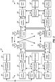
- FIG. 2 shows a block diagram of a design of base station/eNB 110 and UE 120, which may be one of the base stations/eNBs and one of the UEs in FIG. 1 .
- Base station 110 may be equipped with T antennas 234a through 234t
- UE 120 may be equipped with R antennas 252a through 252r, where in general and .
- a transmit processor 220 may receive data from a data source 212 for one or more UEs, select one or more modulation and coding schemes (MCS) for each UE based on CQIs received from the UE, process (e.g., encode and modulate) the data for each UE based on the MCS(s) selected for the UE, and provide data symbols for all UEs. Transmit processor 220 may also process system information (e.g., for SRPI, etc.) and control information (e.g., CQI requests, grants, upper layer signaling, etc.) and provide overhead symbols and control symbols.
- MCS modulation and coding schemes
- Processor 220 may also generate reference symbols for reference signals (e.g., the CRS) and synchronization signals (e.g., the PSS and SSS).
- a transmit (TX) multiple-input multiple-output (MIMO) processor 230 may perform spatial processing (e.g., precoding) on the data symbols, the control symbols, the overhead symbols, and/or the reference symbols, if applicable, and may provide T output symbol streams to T modulators (MODs) 232a through 232t. Each modulator 232 may process a respective output symbol stream (e.g., for OFDM, etc.) to obtain an output sample stream.
- TX transmit
- MIMO multiple-input multiple-output
- MIMO multiple-input multiple-output
- Each modulator 232 may process a respective output symbol stream (e.g., for OFDM, etc.) to obtain an output sample stream.
- Each modulator 232 may further process (e.g., convert to analog, amplify, filter, and upconvert) the output sample stream to obtain a downlink signal.
- T downlink signals from modulators 232a through 232t may be transmitted via T antennas 234a through 234t, respectively.
- antennas 252a through 252r may receive the downlink signals from base station 110 and/or other base stations and may provide received signals to demodulators (DEMODs) 254a through 254r, respectively.
- Each demodulator 254 may condition (e.g., filter, amplify, downconvert, and digitize) its received signal to obtain input samples.
- Each demodulator 254 may further process the input samples (e.g., for OFDM, etc.) to obtain received symbols.
- a MIMO detector 256 may obtain received symbols from all R demodulators 254a through 254r, perform MIMO detection on the received symbols if applicable, and provide detected symbols.
- a receive processor 258 may process (e.g., demodulate and decode) the detected symbols, provide decoded data for UE 120 to a data sink 260, and provide decoded control information and system information to a controller/processor 280.
- a channel processor may determine RSRP, RSSI, RSRQ, CQI, etc.
- a transmit processor 264 may receive and process data from a data source 262 and control information (e.g., for reports comprising RSRP, RSSI, RSRQ, CQI, etc.) from controller/processor 280. Processor 264 may also generate reference symbols for one or more reference signals. The symbols from transmit processor 264 may be precoded by a TX MIMO processor 266 if applicable, further processed by modulators 254a through 254r (e.g., for SC-FDM, OFDM, etc.), and transmitted to base station 110.
- control information e.g., for reports comprising RSRP, RSSI, RSRQ, CQI, etc.
- Processor 264 may also generate reference symbols for one or more reference signals.
- the symbols from transmit processor 264 may be precoded by a TX MIMO processor 266 if applicable, further processed by modulators 254a through 254r (e.g., for SC-FDM, OFDM, etc.), and transmitted to base station 110.
- the uplink signals from UE 120 and other UEs may be received by antennas 234, processed by demodulators 232, detected by a MIMO detector 236 if applicable, and further processed by a receive processor 238 to obtain decoded data and control information sent by UE 120.
- Processor 238 may provide the decoded data to a data sink 239 and the decoded control information to controller/processor 240.
- Base station 110 may include communication unit 244 and communicate to network controller 130 via communication unit 244.
- Network controller 130 may include communication unit 294, controller/processor 290, and memory 292.
- Controllers/processors 240 and 280 may direct the operation at base station 110 and UE 120, respectively.
- Processor 240 and/or other processors and modules at base station 110, and/or processor 280 and/or other processors and modules at UE 120, may perform or direct processes for the techniques described herein.
- Memories 242 and 282 may store data and program codes for base station 110 and UE 120, respectively.
- a scheduler 246 may schedule UEs for data transmission on the downlink and/or uplink.
- the base station 110 may be configured to determine a bundling size based at least in part on a data allocation size and precode data in bundled contiguous resource blocks of the determined bundling size, wherein resource blocks in each bundle may be precoded with a common precoding matrix. That is, reference signals such as UE-RS and/or data in the resource blocks may be precoded using the same precoder.
- the power level used for the UE-RS in each RB (resource block) of the bundled RBs may also be the same.
- the UE 120 may be configured to perform complementary processing to decode data transmitted from the base station 110. For example, the UE 120 may be configured to determine a bundling size based on a data allocation size of received data transmitted from a base station in bundles of contiguous resource blocks (RBs), wherein at least one reference signal in resource blocks in each bundle are precoded with a common precoding matrix, estimate at least one precoded channel based on the determined bundling size and one or more reference signals (RSs) transmitted from the base station, and decode the received bundles using the estimated precoded channel.
- RBs resource blocks
- RSs reference signals
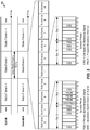
- FIG. 3 shows an exemplary frame structure 300 for FDD in LTE.
- the transmission timeline for each of the downlink and uplink may be partitioned into units of radio frames.
- Each radio frame may have a predetermined duration (e.g., 10 milliseconds (ms)) and may be partitioned into 10 subframes with indices of 0 through 9.
- Each subframe may include two slots.
- Each radio frame may thus include 20 slots with indices of 0 through 19.
- Each slot may include L symbol periods, e.g., seven symbol periods for a normal cyclic prefix (as shown in FIG. 3 ) or six symbol periods for an extended cyclic prefix.
- the 2L symbol periods in each subframe may be assigned indices of 0 through 2L-1.
- an eNB may transmit a primary synchronization signal (PSS) and a secondary synchronization signal (SSS) on the downlink in the center 1.08 MHz of the system bandwidth for each cell supported by the eNB.
- PSS and SSS may be transmitted in symbol periods 6 and 5, respectively, in subframes 0 and 5 of each radio frame with the normal cyclic prefix, as shown in FIG. 3 .
- the PSS and SSS may be used by UEs for cell search and acquisition.
- the eNB may transmit a cell-specific reference signal (CRS) across the system bandwidth for each cell supported by the eNB.
- the CRS may be transmitted in certain symbol periods of each subframe and may be used by the UEs to perform channel estimation, channel quality measurement, and/or other functions.
- the eNB may also transmit a physical broadcast channel (PBCH) in symbol periods 0 to 3 in slot 1 of certain radio frames.
- PBCH physical broadcast channel
- the PBCH may carry some system information.
- the eNB may transmit other system information such as system information blocks (SIBs) on a physical downlink shared channel (PDSCH) in certain subframes.
- SIBs system information blocks
- PDSCH physical downlink shared channel
- the eNB may transmit control information/data on a physical downlink control channel (PDCCH) in the first B symbol periods of a subframe, where B may be configurable for each subframe.
- the eNB may transmit traffic data and/or other data on the PDSCH in the remaining symbol periods of each subframe.
- UEs may signal their capabilities to the network to inform the network about specific features supported by the UEs. For example, a UE may signal the maximum number of multiple-input multiple-output (MIMO) layers supported for downlink (DL) reception. As another example, the UE may signal the maximum number of channel state information (CSI) processes supported in coordinated multipoint (CoMP). For CoMP with carrier aggregation (CA), the UE may signal the maximum number of CSI processes supported per component carrier (CC).
- MIMO multiple-input multiple-output
- CSI channel state information
- CoMP coordinated multipoint
- CA carrier aggregation
- CC component carrier
- the maximum number of supported MIMO layers indicates the maximum number of supported layers for DL spatial multiplexing.
- the maximum number of supported MIMO layers may depend, for example, on the number of UE receive antennas, the UE processing capability, and other implementation specific factors.
- the network may use the number of layers signaled by the UE to determine the bitwidth for rank indicator (RI) signaling.
- RI rank indicator
- the bitwidth may be chosen as the maximum possible rank which is the minimum of the number of e Node B (eNB) antennas and UE receive antennas.
- FIG. 4 is a table 400 illustrating example CSI feedback parameters, according to certain aspects of the present disclosure.
- CSI feedback related parameters are derived based on the signaled UE capability. As seen in FIG. 4 , CSI feedback parameters may be determined based on the signaled UE capability on a per-CC basis.
- the UE indicates the UE capability per band and band combination. For example, assuming a three band scenario: Band A, Band B, Band C and letting P denote the UE capability, the UE can signal different UE capabilities for different CA combinations. For CA of Band A and Band B, the UE may signal support of a first combination of UE capabilities P 11 and P 12 . For CA of another combination of bands, Band A and Band C, the UE may signal support of a second combination of UE capabilities P 21 and P 22 . P 11 may be different from P 21 , and P 12 may be different from P 22 , although both correspond to a CC in Band A (e.g., to signal that the UE supports a higher UE capability one either of the two bands but not both).
- the UE may signal multiple capabilities for the same band combination.
- the UE may signal support for a combination of UE capabilities P 31 and P 32 .
- the UE may signal support for a second, different, combination of UE capabilities P 41 and P 42 .
- One use case for signaling different UE capabilities for the same CA combination is to indicate that a higher capability can be supported on either Band A or Band B, but not both.
- Such signaling leads to ambiguity between the UE and network, as the UE may not know which of the two pairs of UE capabilities was used at the network.
- the UE supports a first combination of UE capabilities P 11 , P 12 if there is no intra-band CA within each band.
- the UE supports the combination of UE capabilities P 21 , P 22 .
- the network configures two CCs and configures reference signals (RSs) (e.g., cell-specific reference signal (CRS) or CSI-RS) for four antenna ports on each CC.
- RSs reference signals
- CRS cell-specific reference signal
- CSI-RS channel-specific reference signal
- the UE cannot determine whether a maximum of four layers (the UE capability) should be supported on CC1 or CC2.
- the UE only knows that one of the two CCs could support such a value. Since the bitwidth of the RI report depends on this number, there is ambiguity as to which bitwidth should be used by the UE on CC1 and CC2, respectively.
- the number of configured CSI processes is 2 or 3, and the timeline parameter is 5.
- FDD frequency division duplexing
- signaling of multiple UE capabilities for the same band combination is not allowed.
- the UE cannot signal multiple values of UE capabilities and ambiguity may be eliminated.
- the maximum value of the UE capability may be used in an analogous fashion. However, this solution may work for some types of UE capability (e.g., max number of MIMO layers) but not for others (e.g., max # of CSI processes). If the UE capability is UE complexity driven, taking the maximum may exceed the UE's computational resources.
- band combination may be selected according to a deterministic rule. For example, the first band combination that is signaled may always be selected. This rule may be a possible option if it is clear at both the UE and the network which band combination should be considered the "first.”
- the list of band combinations may be ordered according to a deterministic rule, for example, alphabetically. Then the UE may select the first listed combination in the alphabetical list. This option may avoid ambiguity even if UE and network order/store UE capabilities differently.
- alphabetical ordering implies sorting the band combinations first according to their first entry, then according to their second, third, etc.
- the network may signal to the UE which of the ambiguous band combinations it has selected. For example, the network may inform the UE which band combination the UE should assume. Alternatively, the network may signal a new set of UE capabilities that are a combination of the ambiguous ones-but do not directly correspond to a single signaled band combination. In this case, the network may need to ensure that the new set of UE capabilities burdens the UE less than any of the ambiguous UE capabilities.
- CA-dependent capability ambiguity may be resolved.
- RI bitwidth may be based on the total max number of layers in a band, regardless of how many CCs the UE is configured in the band-in the example provided, based on 4 layers. In a second alternative, RI bitwidth may further depend on how many carriers a UE is configured in a band. In this case, if one CC is configured on band A, the RI may be based on 4 layers. Alternatively, if two or more CCs are configured on band A, the RI may be based on 2 layers.
- FIG. 5 illustrates example operations 500 for wireless communications by a user equipment (UE), in accordance with certain aspects of the present disclosure.
- the UE determines capabilities of the UE to support at least one of multiple-input multiple-output (MIMO) or coordinated multipoint (CoMP) features on different operating frequency bands of a radio access network (RAN).
- MIMO multiple-input multiple-output
- CoMP coordinated multipoint
- the UE capabilities may include a number of MIMO layers supported for DL reception or a number of CSI processes supported for channel feedback.
- the UE signals, to a base station (BS) of the RAN, a first combination of capabilities of the UE for a combination of bands.
- BS base station
- the UE signals, to the BS, a second combination of capabilities, different than the first combination of capabilities, for the combination of bands.
- the first combination of capabilities indicates a first set of capabilities supported for a first band and a second set of capabilities supported for a second band and the second combination of capabilities indicates a third set of capabilities, different than the first set, for the first band and a fourth set of capabilities, different than the second set, for the second band.
- the UE identifies, based on one or more criteria, a particular combination of capabilities to be used to communicate with the BS.
- the UE may identify the combination of capabilities by taking a minimum common value for one or more capabilities in each of the first and second sets. Alternatively, the UE may take a maximum common value.
- the UE may indentify the combination of capabilities to use by applying a deterministic rule. For example, the rule may be based on an order in which the combinations of capabilities were signaled. Alternatively, the rule may be based on an ordered list of band combinations, independent of an order in which the combinations of capabilities were signaled.
- the UE may receive signaling from the BS indicating the combination of capabilities to use. For some embodiments, the BS may signal a different combination of capabilities than either the first or second combinations of capabilities.
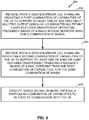
- FIG. 6 illustrates example operations 600 for wireless communications by a base station (BS), in accordance with certain aspects of the present disclosure.
- BS base station
- the BS receives, from a user equipment (UE), signaling indicating a first combination of capabilities of the UE to support at least one of multiple-input multiple-output (MIMO) or coordinated multipoint (CoMP) features on different operating frequency bands of a radio access network (RAN) for a combination of bands.
- MIMO multiple-input multiple-output
- CoMP coordinated multipoint
- the BS receives, from the UE, signaling indicating a second combination of capabilities of the UE to support at least one of MIMO or CoMP features on different operating frequency bands of a RAN, different than the first combination of capabilities, for the combination of bands.
- the BS identifies, based on one or more criteria, a particular combination of capabilities to be used to communicate with the UE.
- the various operations of methods described above may be performed by any suitable means capable of performing the corresponding functions.
- the means may include various hardware and/or software component(s) and/or module(s), including, but not limited to a circuit, an application specific integrate circuit (ASIC), or processor.
- ASIC application specific integrate circuit
- determining encompasses a wide variety of actions. For example, “determining” may include calculating, computing, processing, deriving, investigating, looking up (e.g., looking up in a table, a database or another data structure), ascertaining and the like. Also, “determining” may include receiving (e.g., receiving information), accessing (e.g., accessing data in a memory) and the like. Also, “determining” may include resolving, selecting, choosing, establishing and the like.
- any suitable means capable of performing the operations such as various hardware and/or software component(s), circuits, and/or module(s).
- any operations illustrated in the Figures may be performed by corresponding functional means capable of performing the operations.
- DSP digital signal processor
- ASIC application specific integrated circuit
- FPGA field programmable gate array signal
- PLD programmable logic device
- a general-purpose processor may be a microprocessor, but in the alternative, the processor may be any commercially available processor, controller, microcontroller or state machine.
- a processor may also be implemented as a combination of computing devices, e.g., a combination of a DSP and a microprocessor, a plurality of microprocessors, one or more microprocessors in conjunction with a DSP core, or any other such configuration.
- a software module may reside in any form of storage medium that is known in the art. Some examples of storage media that may be used include random access memory (RAM), read only memory (ROM), flash memory, EPROM memory, EEPROM memory, registers, a hard disk, a removable disk, a CD-ROM and so forth.
- RAM random access memory
- ROM read only memory
- flash memory EPROM memory
- EEPROM memory EEPROM memory
- registers a hard disk, a removable disk, a CD-ROM and so forth.
- a software module may comprise a single instruction, or many instructions, and may be distributed over several different code segments, among different programs, and across multiple storage media.
- a storage medium may be coupled to a processor such that the processor can read information from, and write information to, the storage medium. In the alternative, the storage medium may be integral to the processor.
- the methods disclosed herein comprise one or more steps or actions for achieving the described method.
- the method steps and/or actions may be interchanged with one another without departing from the scope of the claims.
- the order and/or use of specific steps and/or actions may be modified without departing from the scope of the claims.
- a storage media may be any available media that can be accessed by a computer.
- such computer-readable media can comprise RAM, ROM, EEPROM, CD-ROM or other optical disk storage, magnetic disk storage or other magnetic storage devices, or any other medium that can be used to carry or store desired program code in the form of instructions or data structures and that can be accessed by a computer.
- Disk and disc include compact disc (CD), laser disc, optical disc, digital versatile disc (DVD), floppy disk, and Blu-ray® disc where disks usually reproduce data magnetically, while discs reproduce data optically with lasers.
- certain aspects may comprise a computer program product for performing the operations presented herein.
- a computer program product may comprise a computer readable medium having instructions stored (and/or encoded) thereon, the instructions being executable by one or more processors to perform the operations described herein.
- the computer program product may include packaging material.
- Software or instructions may also be transmitted over a transmission medium.
- a transmission medium For example, if the software is transmitted from a website, server, or other remote source using a coaxial cable, fiber optic cable, twisted pair, digital subscriber line (DSL), or wireless technologies such as infrared, radio, and microwave, then the coaxial cable, fiber optic cable, twisted pair, DSL, or wireless technologies such as infrared, radio, and microwave are included in the definition of transmission medium.
- DSL digital subscriber line
- modules and/or other appropriate means for performing the methods and techniques described herein can be downloaded and/or otherwise obtained by a user terminal and/or base station as applicable.
- a user terminal and/or base station can be coupled to a server to facilitate the transfer of means for performing the methods described herein.
- various methods described herein can be provided via storage means (e.g., RAM, ROM, a physical storage medium such as a compact disc (CD) or floppy disk, etc.), such that a user terminal and/or base station can obtain the various methods upon coupling or providing the storage means to the device.
- storage means e.g., RAM, ROM, a physical storage medium such as a compact disc (CD) or floppy disk, etc.
- CD compact disc
- floppy disk etc.
- any other suitable technique for providing the methods and techniques described herein to a device can be utilized.
- the techniques provided herein may be utilized in a variety of applications.
- the techniques presented herein may be incorporated in an access point station, an access terminal, a mobile handset, or other type of wireless device with processing logic and elements to perform the techniques provided herein.
Claims (15)
- Verfahren zur drahtlosen Kommunikation durch eine Benutzervorrichtung (120a-d), UE, umfassend:Bestimmen, ob eine UE (120a-d) Fähigkeiten besitzt, mindestens eines von Multiple-Input Multiple-Output, MIMO, oder koordinierte Multipunkt-, CoMP,-Merkmale auf verschiedenen Betriebsfrequenzbändern eines Funkzugangsnetzes, RAN, zu unterstützen;Signalisieren einer ersten Kombination von MIMO- oder CoMP-Fähigkeiten der UE (120a-d) für eine Kombination von zwei oder mehr Betriebsfrequenzbändern in Trägeraggregation an eine Basisstation (110a-d), BS, des RAN;Signalisieren einer zweiten Kombination von MIMO- oder CoMP-Fähigkeiten, die sich von der ersten Kombination von Fähigkeiten unterscheidet, für die gleiche von mindestens einem von MIMO- oder CoMP-Merkmalen und der gleichen Kombination von Bändern an die BS (110a-d); undIdentifizieren einer bestimmten Kombination von Fähigkeiten, die zur Kommunikation mit der BS (110a-d) zu verwenden sind, anhand eines oder mehrerer Kriterien.
- Verfahren nach Anspruch 1, wobei das Identifizieren umfasst:
Anwenden einer deterministischen Regel, um zu bestimmen, welche der ersten Kombination von Fähigkeiten oder der zweiten Kombination von Fähigkeiten zu verwenden ist. - Verfahren nach Anspruch 2, wobei die deterministische Regel auf einer Reihenfolge basiert, in der die erste Kombination von Fähigkeiten und die zweite Kombination von Fähigkeiten signalisiert wurden.
- Verfahren nach Anspruch 2, wobei die deterministische Regel auf einer geordneten Liste von Bandkombinationen basiert, unabhängig von einer Reihenfolge, in der die erste Kombination von Fähigkeiten und die zweite Kombination von Fähigkeiten signalisiert wurden.
- Verfahren nach Anspruch 1, wobei das Identifizieren Empfangen von Signalen von der BS (110a-d) umfasst, die eine Kombination von Einsatzmöglichkeiten anzeigen.
- Verfahren nach Anspruch 5, wobei die BS-(110a-d)-Signalisierung eine andere Kombination von Fähigkeiten anzeigt als entweder die erste Kombination von Fähigkeiten oder die zweite Kombination von Fähigkeiten.
- Verfahren zur drahtlosen Kommunikation durch eine Basisstation (110a-d), BS, umfassend:Empfangen einer Signalisierung von einer Benutzervorrichtung (120a-d), UE, die eine erste Kombination von MIMO- oder CoMP-Fähigkeiten der UE (120a-d) anzeigt, ob mindestens eines von Multiple-Input Multiple-Output, MIMO, oder koordinierte Multipunkt-, CoMP,-Merkmalen auf verschiedenen Betriebsfrequenzbändern eines Funkzugangsnetzes, RAN, für eine Kombination von zwei oder mehr Betriebsfrequenzbändern in Trägeraggregation unterstütz wird;Empfangen einer Signalisierung von der UE (120a-d), die eine zweite Kombination von MIMO- oder CoMP-Fähigkeiten der UE (120a-d) zum Unterstützen mindestens eines von MIMO- oder CoMP-Merkmalen auf verschiedenen Betriebsfrequenzbändern eines RAN anzeigt, die sich von der ersten Kombination von Fähigkeiten unterscheidet, für dasselbe von mindestens einem von MIMO- oder CoMP-Merkmalen und der gleichen Kombination von Bändern; undIdentifizieren einer bestimmten Kombination von Fähigkeiten, die zum Kommunizieren mit der UE (120a-d) zu nutzen sind, anhand eines oder mehrerer Kriterien.
- Verfahren nach Anspruch 7, wobei das Identifizieren umfasst:
Anwenden einer deterministischen Regel, um zu bestimmen, welche der ersten Kombination von Fähigkeiten oder der zweiten Kombination von Fähigkeiten zu verwenden ist. - Verfahren nach Anspruch 8, wobei die deterministische Regel auf einer Reihenfolge basiert, in der die erste Kombination von Fähigkeiten und die zweite Kombination von Fähigkeiten signalisiert wurden.
- Verfahren nach Anspruch 8, wobei die deterministische Regel auf einer geordneten Liste von Bandkombinationen basiert, unabhängig von einer Reihenfolge, in der die erste Kombination von Fähigkeiten und die zweite Kombination von Fähigkeiten signalisiert wurden.
- Verfahren nach Anspruch 7, ferner umfassend Signalisieren einer Anzeige an die UE (120a-d) über eine Kombination von Einsatzmöglichkeiten.
- Verfahren nach Anspruch 11, wobei die BS-(110a-d)-Signalisierung eine andere Kombination von Fähigkeiten anzeigt als entweder die erste Kombination von Fähigkeiten oder die zweite Kombination von Fähigkeiten.
- Vorrichtung zur drahtlosen Kommunikation durch eine Benutzervorrichtung (120a-d), UE, umfassend:Mittel zum Bestimmen, ob eine UE (120a-d) Fähigkeiten besitzt, mindestens eines von Multiple-Input Multiple-Output, MIMO, oder koordinierte Multipunkt-, CoMP,-Merkmale auf verschiedenen Betriebsfrequenzbändern eines Funkzugangsnetzes, RAN, zu unterstützen;Mittel zum Signalisieren einer ersten Kombination von MIMO- oder CoMP-Fähigkeiten der UE (120a-d) für eine Kombination von zwei oder mehr Betriebsfrequenzbändern in Trägeraggregation an eine Basisstation (110a-d), BS, des RAN;Mittel zum Signalisieren einer zweiten Kombination von MIMO- oder CoMP-Fähigkeiten, die sich von der ersten Kombination von Fähigkeiten unterscheidet, für die gleiche von mindestens einem von MIMO- oder CoMP-Merkmalen und der gleichen Kombination von Bändern an die BS (110a-d); undMittel zum Identifizieren einer bestimmten Kombination von Fähigkeiten, die zur Kommunikation mit der BS (110a-d) zu verwenden sind, anhand eines oder mehrerer Kriterien.
- Vorrichtung zur drahtlosen Kommunikation durch eine Basisstation (110a-d), BS, umfassend:Mittel zum Empfangen einer Signalisierung von einer Benutzervorrichtung (120a-d), UE, die eine erste Kombination von MIMO- oder CoMP-Fähigkeiten der UE (120a-d) anzeigt, ob mindestens eines von Multiple-Input Multiple-Output, MIMO, oder koordinierte Multipunkt-, CoMP,-Merkmalen auf verschiedenen Betriebsfrequenzbändern eines Funkzugangsnetzes, RAN, für eine Kombination von zwei oder mehr Betriebsfrequenzbändern in Trägeraggregation unterstütz wird;Mittel zum Empfangen einer Signalisierung von der UE (120a-d), die eine zweite Kombination von MIMO- oder CoMP-Fähigkeiten der UE (120a-d) zum Unterstützen mindestens eines von MIMO- oder CoMP-Merkmalen auf verschiedenen Betriebsfrequenzbändern eines RAN anzeigt, die sich von der ersten Kombination von Fähigkeiten unterscheidet, für dasselbe von mindestens einem von MIMO- oder CoMP-Merkmalen und der gleichen Kombination von Bändern; undMittel zum Identifizieren einer bestimmten Kombination von Fähigkeiten, die zum Kommunizieren mit der UE (120a-d) zu nutzen sind, anhand eines oder mehrerer Kriterien.
- Computerprogramm, umfassend Anweisungen zum Ausführen des Verfahrens nach einem der Ansprüche 1-6 oder 7-12.
Applications Claiming Priority (3)
| Application Number | Priority Date | Filing Date | Title |
|---|---|---|---|
| US201361754407P | 2013-01-18 | 2013-01-18 | |
| US14/084,804 US9237440B2 (en) | 2013-01-18 | 2013-11-20 | Methods and apparatus for resolving ambiguous user equipment (UE) capability signaling |
| PCT/US2013/071140 WO2014113137A1 (en) | 2013-01-18 | 2013-11-21 | Methods and apparatus for resolving ambiguous user equipment (ue) capability signaling |
Publications (2)
| Publication Number | Publication Date |
|---|---|
| EP2946482A1 EP2946482A1 (de) | 2015-11-25 |
| EP2946482B1 true EP2946482B1 (de) | 2019-07-31 |
Family
ID=51207618
Family Applications (1)
| Application Number | Title | Priority Date | Filing Date |
|---|---|---|---|
| EP13802188.6A Active EP2946482B1 (de) | 2013-01-18 | 2013-11-21 | Verfahren und vorrichtung zur auflösung von mehrdeutiger kapazitätssignalisierung eines benutzergeräts |
Country Status (8)
| Country | Link |
|---|---|
| US (1) | US9237440B2 (de) |
| EP (1) | EP2946482B1 (de) |
| JP (1) | JP5932169B2 (de) |
| KR (1) | KR101684401B1 (de) |
| CN (1) | CN104919718B (de) |
| ES (1) | ES2753235T3 (de) |
| HU (1) | HUE044681T2 (de) |
| WO (1) | WO2014113137A1 (de) |
Families Citing this family (27)
| Publication number | Priority date | Publication date | Assignee | Title |
|---|---|---|---|---|
| US9237440B2 (en) * | 2013-01-18 | 2016-01-12 | Qualcomm Incorporated | Methods and apparatus for resolving ambiguous user equipment (UE) capability signaling |
| JP6253263B2 (ja) * | 2013-05-31 | 2017-12-27 | 株式会社Nttドコモ | ユーザ装置、基地局、ユーザ装置種類情報通知方法、及びユーザ装置種類情報受信方法 |
| US9713083B2 (en) * | 2013-08-28 | 2017-07-18 | Noki Technologies Oy | LTE advanced service indicator |
| EP3251264B1 (de) * | 2015-01-30 | 2018-04-25 | Telefonaktiebolaget LM Ericsson (publ) | Singalisierung der kommunikationsfähigkeiten eines teilnehmers in einzelnen trägerkomponenten in einem trägeraggregation verwendenden drahtlosen kommunikationssystem |
| WO2016126099A1 (ko) * | 2015-02-05 | 2016-08-11 | 엘지전자(주) | 무선 통신 시스템에서 csi를 피드백하기 위한 방법 및 이를 위한 장치 |
| US10236951B2 (en) | 2015-04-10 | 2019-03-19 | Lg Electronics Inc. | Method for reporting channel state information in wireless communication system and device therefor |
| CN112865847B (zh) | 2015-04-10 | 2023-09-12 | Lg 电子株式会社 | 在无线通信系统中报告信道状态信息的方法及其设备 |
| WO2017006871A1 (ja) * | 2015-07-03 | 2017-01-12 | シャープ株式会社 | 端末装置、基地局装置、通信方法、および、集積回路 |
| EP3342229A4 (de) * | 2015-09-30 | 2019-03-20 | MediaTek Singapore Pte Ltd. | Verfahren und vorrichtung zur decodierung von dl-phy-kanälen in einem schmalbandsystem |
| WO2017075746A1 (en) * | 2015-11-02 | 2017-05-11 | Qualcomm Incorporated | Techniques for managing cell identifiers and other parameters for flexible duplex operations |
| JP2019009484A (ja) * | 2015-11-13 | 2019-01-17 | シャープ株式会社 | 端末装置、基地局装置、通信方法、および、集積回路 |
| JP2019009483A (ja) * | 2015-11-13 | 2019-01-17 | シャープ株式会社 | 端末装置、基地局装置、通信方法、および、集積回路 |
| EP3190847B1 (de) | 2016-01-08 | 2020-07-22 | IPCom GmbH & Co. KG | Kapazitätskostensignalisierung |
| CN107040355A (zh) * | 2016-02-04 | 2017-08-11 | 中兴通讯股份有限公司 | 一种兼容的信令发送方法和装置 |
| WO2017164590A1 (ko) * | 2016-03-24 | 2017-09-28 | 엘지전자 주식회사 | 차세대 통신 시스템에서 참조 신호를 송수신하는 방법 및 이를 위한 장치 |
| CN109479191B (zh) * | 2016-07-15 | 2022-05-31 | 索尼集团公司 | 由无线通信装置支持的能力组合的灵活指示的方法、装置和系统 |
| CN108282774B (zh) * | 2017-01-06 | 2022-02-25 | 华为技术有限公司 | 一种通知通信设备的能力信息的方法及设备 |
| US10477552B2 (en) * | 2017-02-13 | 2019-11-12 | Qualcomm Incorporated | Techniques for handling wide bandwidth communications |
| US11259203B2 (en) * | 2018-01-07 | 2022-02-22 | Htc Corporation | Device and method of handling communication device capabilities |
| CN110035427B (zh) | 2018-01-12 | 2021-01-08 | 维沃移动通信有限公司 | 一种时隙偏移确定方法和设备 |
| WO2019158208A1 (en) * | 2018-02-16 | 2019-08-22 | Nokia Technologies Oy | Support for receive-limited user equipment in wireless environments |
| WO2020174552A1 (ja) * | 2019-02-25 | 2020-09-03 | 株式会社Nttドコモ | ユーザ装置及び通信方法 |
| US11394433B2 (en) * | 2019-03-28 | 2022-07-19 | Qualcomm Incorporated | Full dimension multiple-input multiple-output baseband capability indication |
| JP7422163B2 (ja) * | 2019-11-15 | 2024-01-25 | 株式会社Nttドコモ | 端末、基地局、及び通信方法 |
| US20220039047A1 (en) * | 2020-08-03 | 2022-02-03 | Mediatek Inc. | Apparatuses and methods for reducing the number of multiple-input-multiple-output (mimo) layers |
| WO2022226871A1 (en) * | 2021-04-29 | 2022-11-03 | Qualcomm Incorporated | Capability reporting based on wireless device cooperation |
| KR102502380B1 (ko) | 2021-10-21 | 2023-02-21 | 에스케이텔레콤 주식회사 | 미확인 기능의 단말 지원 여부를 결정하기 위한 장치 및 이를 위한 방법 |
Family Cites Families (15)
| Publication number | Priority date | Publication date | Assignee | Title |
|---|---|---|---|---|
| US6600917B1 (en) | 1999-10-04 | 2003-07-29 | Telefonaktiebolaget Lm Ericsson (Publ) | Telecommunications network broadcasting of service capabilities |
| WO2010019087A1 (en) * | 2008-08-13 | 2010-02-18 | Telefonaktiebolaget L M Ericsson (Publ) | Reporting of multiple if/rat layer restrictions |
| WO2011087408A1 (en) | 2010-01-13 | 2011-07-21 | Telefonaktiebolaget L M Ericsson (Publ) | Methods and arrangements in a cellular network |
| US20110267948A1 (en) * | 2010-05-03 | 2011-11-03 | Koc Ali T | Techniques for communicating and managing congestion in a wireless network |
| US8649326B2 (en) * | 2010-07-06 | 2014-02-11 | Htc Corporation | Method of handling capability information of a mobile device and related communication device |
| US8717920B2 (en) | 2010-10-08 | 2014-05-06 | Telefonaktiebolaget L M Ericsson (Publ) | Signalling mechanism for multi-tiered intra-band carrier aggregation |
| US9467885B2 (en) | 2010-11-08 | 2016-10-11 | Qualcomm Incorporated | Inter-frequency measurement control in a multi-carrier system |
| JP2012204910A (ja) * | 2011-03-24 | 2012-10-22 | Sharp Corp | 通信システム、基地局装置、移動局装置、移動局装置処理能力の管理方法及び集積回路 |
| WO2012141634A1 (en) | 2011-04-13 | 2012-10-18 | Telefonaktiebolaget L M Ericsson (Publ) | Method and device for determining a number of mimo layers |
| CN102255689B (zh) * | 2011-07-08 | 2018-05-04 | 中兴通讯股份有限公司 | 一种信道状态信息的处理方法、装置及系统 |
| US20140169317A1 (en) * | 2011-07-25 | 2014-06-19 | Broadcom Corporation | Method and apparatus for switching antenna port configurations |
| ES2735755T3 (es) * | 2011-08-16 | 2019-12-20 | Ericsson Telefon Ab L M | Extensiones de capacidad para Servicios de Difusión-Multidifusión Multimedia |
| US9042938B2 (en) * | 2012-12-27 | 2015-05-26 | Google Technology Holdings LLC | Method and apparatus for device-to-device communication |
| US9692584B2 (en) * | 2013-01-17 | 2017-06-27 | Telefonatiebolaget L M Ericsson (Publ) | Methods of radio communications using different subframe configurations and related radio and/or network nodes |
| US9237440B2 (en) * | 2013-01-18 | 2016-01-12 | Qualcomm Incorporated | Methods and apparatus for resolving ambiguous user equipment (UE) capability signaling |
-
2013
- 2013-11-20 US US14/084,804 patent/US9237440B2/en active Active
- 2013-11-21 HU HUE13802188 patent/HUE044681T2/hu unknown
- 2013-11-21 EP EP13802188.6A patent/EP2946482B1/de active Active
- 2013-11-21 CN CN201380070136.3A patent/CN104919718B/zh active Active
- 2013-11-21 JP JP2015553723A patent/JP5932169B2/ja active Active
- 2013-11-21 KR KR1020157021217A patent/KR101684401B1/ko active IP Right Grant
- 2013-11-21 ES ES13802188T patent/ES2753235T3/es active Active
- 2013-11-21 WO PCT/US2013/071140 patent/WO2014113137A1/en active Application Filing
Non-Patent Citations (1)
| Title |
|---|
| SAMSUNG: "UE capability signaling structure w.r.t carrier aggregation, MIMO and measurement gap", 3GPP DRAFT; R2-110874 CA_MIMO CAPABILITY, 3RD GENERATION PARTNERSHIP PROJECT (3GPP), MOBILE COMPETENCE CENTRE ; 650, ROUTE DES LUCIOLES ; F-06921 SOPHIA-ANTIPOLIS CEDEX ; FRANCE, vol. RAN WG2, no. Taipei, Taiwan; 20110221, 15 February 2011 (2011-02-15), XP050493635 * |
Also Published As
| Publication number | Publication date |
|---|---|
| WO2014113137A1 (en) | 2014-07-24 |
| JP2016507990A (ja) | 2016-03-10 |
| CN104919718A (zh) | 2015-09-16 |
| KR20150110572A (ko) | 2015-10-02 |
| ES2753235T3 (es) | 2020-04-07 |
| EP2946482A1 (de) | 2015-11-25 |
| HUE044681T2 (hu) | 2019-11-28 |
| KR101684401B1 (ko) | 2016-12-08 |
| CN104919718B (zh) | 2018-01-12 |
| JP5932169B2 (ja) | 2016-06-08 |
| US9237440B2 (en) | 2016-01-12 |
| US20140204848A1 (en) | 2014-07-24 |
Similar Documents
| Publication | Publication Date | Title |
|---|---|---|
| EP2946482B1 (de) | Verfahren und vorrichtung zur auflösung von mehrdeutiger kapazitätssignalisierung eines benutzergeräts | |
| US11032732B2 (en) | Transport block size determination | |
| US11323994B2 (en) | Control channel design for machine type communications | |
| AU2017337056B2 (en) | Positioning reference signal enhancements | |
| EP2915392B1 (de) | Uplink-reichweitenverbesserungen | |
| US10057815B2 (en) | Physical broadcast channel repetition for evolved machine type communication | |
| CA2980932C (en) | Physical uplink control channel (pucch) configuration for machine type communications (mtc) | |
| WO2018031162A1 (en) | Handover candidate cell identification and radio link failure (rlf) mitigation in coverage areas |
Legal Events
| Date | Code | Title | Description |
|---|---|---|---|
| PUAI | Public reference made under article 153(3) epc to a published international application that has entered the european phase |
Free format text: ORIGINAL CODE: 0009012 |
|
| 17P | Request for examination filed |
Effective date: 20150723 |
|
| AK | Designated contracting states |
Kind code of ref document: A1 Designated state(s): AL AT BE BG CH CY CZ DE DK EE ES FI FR GB GR HR HU IE IS IT LI LT LU LV MC MK MT NL NO PL PT RO RS SE SI SK SM TR |
|
| AX | Request for extension of the european patent |
Extension state: BA ME |
|
| DAX | Request for extension of the european patent (deleted) | ||
| STAA | Information on the status of an ep patent application or granted ep patent |
Free format text: STATUS: EXAMINATION IS IN PROGRESS |
|
| 17Q | First examination report despatched |
Effective date: 20171012 |
|
| GRAP | Despatch of communication of intention to grant a patent |
Free format text: ORIGINAL CODE: EPIDOSNIGR1 |
|
| STAA | Information on the status of an ep patent application or granted ep patent |
Free format text: STATUS: GRANT OF PATENT IS INTENDED |
|
| RIC1 | Information provided on ipc code assigned before grant |
Ipc: H04W 8/22 20090101ALI20190204BHEP Ipc: H04B 7/04 20170101AFI20190204BHEP Ipc: H04B 7/06 20060101ALI20190204BHEP Ipc: H04B 7/024 20170101ALI20190204BHEP Ipc: H04B 7/0413 20170101ALI20190204BHEP Ipc: H04W 8/24 20090101ALI20190204BHEP |
|
| INTG | Intention to grant announced |
Effective date: 20190221 |
|
| GRAS | Grant fee paid |
Free format text: ORIGINAL CODE: EPIDOSNIGR3 |
|
| GRAA | (expected) grant |
Free format text: ORIGINAL CODE: 0009210 |
|
| STAA | Information on the status of an ep patent application or granted ep patent |
Free format text: STATUS: THE PATENT HAS BEEN GRANTED |
|
| AK | Designated contracting states |
Kind code of ref document: B1 Designated state(s): AL AT BE BG CH CY CZ DE DK EE ES FI FR GB GR HR HU IE IS IT LI LT LU LV MC MK MT NL NO PL PT RO RS SE SI SK SM TR |
|
| REG | Reference to a national code |
Ref country code: CH Ref legal event code: EP Ref country code: GB Ref legal event code: FG4D |
|
| REG | Reference to a national code |
Ref country code: AT Ref legal event code: REF Ref document number: 1162052 Country of ref document: AT Kind code of ref document: T Effective date: 20190815 |
|
| REG | Reference to a national code |
Ref country code: IE Ref legal event code: FG4D |
|
| REG | Reference to a national code |
Ref country code: DE Ref legal event code: R096 Ref document number: 602013058550 Country of ref document: DE |
|
| REG | Reference to a national code |
Ref country code: NL Ref legal event code: FP |
|
| REG | Reference to a national code |
Ref country code: HU Ref legal event code: AG4A Ref document number: E044681 Country of ref document: HU |
|
| REG | Reference to a national code |
Ref country code: LT Ref legal event code: MG4D |
|
| REG | Reference to a national code |
Ref country code: AT Ref legal event code: MK05 Ref document number: 1162052 Country of ref document: AT Kind code of ref document: T Effective date: 20190731 |
|
| PG25 | Lapsed in a contracting state [announced via postgrant information from national office to epo] |
Ref country code: LT Free format text: LAPSE BECAUSE OF FAILURE TO SUBMIT A TRANSLATION OF THE DESCRIPTION OR TO PAY THE FEE WITHIN THE PRESCRIBED TIME-LIMIT Effective date: 20190731 Ref country code: PT Free format text: LAPSE BECAUSE OF FAILURE TO SUBMIT A TRANSLATION OF THE DESCRIPTION OR TO PAY THE FEE WITHIN THE PRESCRIBED TIME-LIMIT Effective date: 20191202 Ref country code: BG Free format text: LAPSE BECAUSE OF FAILURE TO SUBMIT A TRANSLATION OF THE DESCRIPTION OR TO PAY THE FEE WITHIN THE PRESCRIBED TIME-LIMIT Effective date: 20191031 Ref country code: AT Free format text: LAPSE BECAUSE OF FAILURE TO SUBMIT A TRANSLATION OF THE DESCRIPTION OR TO PAY THE FEE WITHIN THE PRESCRIBED TIME-LIMIT Effective date: 20190731 Ref country code: NO Free format text: LAPSE BECAUSE OF FAILURE TO SUBMIT A TRANSLATION OF THE DESCRIPTION OR TO PAY THE FEE WITHIN THE PRESCRIBED TIME-LIMIT Effective date: 20191031 Ref country code: HR Free format text: LAPSE BECAUSE OF FAILURE TO SUBMIT A TRANSLATION OF THE DESCRIPTION OR TO PAY THE FEE WITHIN THE PRESCRIBED TIME-LIMIT Effective date: 20190731 Ref country code: SE Free format text: LAPSE BECAUSE OF FAILURE TO SUBMIT A TRANSLATION OF THE DESCRIPTION OR TO PAY THE FEE WITHIN THE PRESCRIBED TIME-LIMIT Effective date: 20190731 |
|
| PG25 | Lapsed in a contracting state [announced via postgrant information from national office to epo] |
Ref country code: IS Free format text: LAPSE BECAUSE OF FAILURE TO SUBMIT A TRANSLATION OF THE DESCRIPTION OR TO PAY THE FEE WITHIN THE PRESCRIBED TIME-LIMIT Effective date: 20191130 Ref country code: LV Free format text: LAPSE BECAUSE OF FAILURE TO SUBMIT A TRANSLATION OF THE DESCRIPTION OR TO PAY THE FEE WITHIN THE PRESCRIBED TIME-LIMIT Effective date: 20190731 Ref country code: RS Free format text: LAPSE BECAUSE OF FAILURE TO SUBMIT A TRANSLATION OF THE DESCRIPTION OR TO PAY THE FEE WITHIN THE PRESCRIBED TIME-LIMIT Effective date: 20190731 Ref country code: AL Free format text: LAPSE BECAUSE OF FAILURE TO SUBMIT A TRANSLATION OF THE DESCRIPTION OR TO PAY THE FEE WITHIN THE PRESCRIBED TIME-LIMIT Effective date: 20190731 Ref country code: GR Free format text: LAPSE BECAUSE OF FAILURE TO SUBMIT A TRANSLATION OF THE DESCRIPTION OR TO PAY THE FEE WITHIN THE PRESCRIBED TIME-LIMIT Effective date: 20191101 |
|
| PG25 | Lapsed in a contracting state [announced via postgrant information from national office to epo] |
Ref country code: TR Free format text: LAPSE BECAUSE OF FAILURE TO SUBMIT A TRANSLATION OF THE DESCRIPTION OR TO PAY THE FEE WITHIN THE PRESCRIBED TIME-LIMIT Effective date: 20190731 |
|
| REG | Reference to a national code |
Ref country code: ES Ref legal event code: FG2A Ref document number: 2753235 Country of ref document: ES Kind code of ref document: T3 Effective date: 20200407 |
|
| PG25 | Lapsed in a contracting state [announced via postgrant information from national office to epo] |
Ref country code: RO Free format text: LAPSE BECAUSE OF FAILURE TO SUBMIT A TRANSLATION OF THE DESCRIPTION OR TO PAY THE FEE WITHIN THE PRESCRIBED TIME-LIMIT Effective date: 20190731 Ref country code: EE Free format text: LAPSE BECAUSE OF FAILURE TO SUBMIT A TRANSLATION OF THE DESCRIPTION OR TO PAY THE FEE WITHIN THE PRESCRIBED TIME-LIMIT Effective date: 20190731 Ref country code: DK Free format text: LAPSE BECAUSE OF FAILURE TO SUBMIT A TRANSLATION OF THE DESCRIPTION OR TO PAY THE FEE WITHIN THE PRESCRIBED TIME-LIMIT Effective date: 20190731 Ref country code: PL Free format text: LAPSE BECAUSE OF FAILURE TO SUBMIT A TRANSLATION OF THE DESCRIPTION OR TO PAY THE FEE WITHIN THE PRESCRIBED TIME-LIMIT Effective date: 20190731 |
|
| PG25 | Lapsed in a contracting state [announced via postgrant information from national office to epo] |
Ref country code: CZ Free format text: LAPSE BECAUSE OF FAILURE TO SUBMIT A TRANSLATION OF THE DESCRIPTION OR TO PAY THE FEE WITHIN THE PRESCRIBED TIME-LIMIT Effective date: 20190731 Ref country code: SK Free format text: LAPSE BECAUSE OF FAILURE TO SUBMIT A TRANSLATION OF THE DESCRIPTION OR TO PAY THE FEE WITHIN THE PRESCRIBED TIME-LIMIT Effective date: 20190731 Ref country code: IS Free format text: LAPSE BECAUSE OF FAILURE TO SUBMIT A TRANSLATION OF THE DESCRIPTION OR TO PAY THE FEE WITHIN THE PRESCRIBED TIME-LIMIT Effective date: 20200224 Ref country code: SM Free format text: LAPSE BECAUSE OF FAILURE TO SUBMIT A TRANSLATION OF THE DESCRIPTION OR TO PAY THE FEE WITHIN THE PRESCRIBED TIME-LIMIT Effective date: 20190731 |
|
| REG | Reference to a national code |
Ref country code: DE Ref legal event code: R097 Ref document number: 602013058550 Country of ref document: DE |
|
| REG | Reference to a national code |
Ref country code: CH Ref legal event code: PL |
|
| PLBE | No opposition filed within time limit |
Free format text: ORIGINAL CODE: 0009261 |
|
| STAA | Information on the status of an ep patent application or granted ep patent |
Free format text: STATUS: NO OPPOSITION FILED WITHIN TIME LIMIT |
|
| PG2D | Information on lapse in contracting state deleted |
Ref country code: IS |
|
| PG25 | Lapsed in a contracting state [announced via postgrant information from national office to epo] |
Ref country code: MC Free format text: LAPSE BECAUSE OF FAILURE TO SUBMIT A TRANSLATION OF THE DESCRIPTION OR TO PAY THE FEE WITHIN THE PRESCRIBED TIME-LIMIT Effective date: 20190731 Ref country code: LU Free format text: LAPSE BECAUSE OF NON-PAYMENT OF DUE FEES Effective date: 20191121 Ref country code: LI Free format text: LAPSE BECAUSE OF NON-PAYMENT OF DUE FEES Effective date: 20191130 Ref country code: CH Free format text: LAPSE BECAUSE OF NON-PAYMENT OF DUE FEES Effective date: 20191130 Ref country code: IS Free format text: LAPSE BECAUSE OF FAILURE TO SUBMIT A TRANSLATION OF THE DESCRIPTION OR TO PAY THE FEE WITHIN THE PRESCRIBED TIME-LIMIT Effective date: 20191030 |
|
| 26N | No opposition filed |
Effective date: 20200603 |
|
| REG | Reference to a national code |
Ref country code: BE Ref legal event code: MM Effective date: 20191130 |
|
| PG25 | Lapsed in a contracting state [announced via postgrant information from national office to epo] |
Ref country code: SI Free format text: LAPSE BECAUSE OF FAILURE TO SUBMIT A TRANSLATION OF THE DESCRIPTION OR TO PAY THE FEE WITHIN THE PRESCRIBED TIME-LIMIT Effective date: 20190731 |
|
| PG25 | Lapsed in a contracting state [announced via postgrant information from national office to epo] |
Ref country code: IE Free format text: LAPSE BECAUSE OF NON-PAYMENT OF DUE FEES Effective date: 20191121 |
|
| PG25 | Lapsed in a contracting state [announced via postgrant information from national office to epo] |
Ref country code: BE Free format text: LAPSE BECAUSE OF NON-PAYMENT OF DUE FEES Effective date: 20191130 |
|
| PG25 | Lapsed in a contracting state [announced via postgrant information from national office to epo] |
Ref country code: CY Free format text: LAPSE BECAUSE OF FAILURE TO SUBMIT A TRANSLATION OF THE DESCRIPTION OR TO PAY THE FEE WITHIN THE PRESCRIBED TIME-LIMIT Effective date: 20190731 |
|
| PG25 | Lapsed in a contracting state [announced via postgrant information from national office to epo] |
Ref country code: MT Free format text: LAPSE BECAUSE OF FAILURE TO SUBMIT A TRANSLATION OF THE DESCRIPTION OR TO PAY THE FEE WITHIN THE PRESCRIBED TIME-LIMIT Effective date: 20190731 |
|
| PG25 | Lapsed in a contracting state [announced via postgrant information from national office to epo] |
Ref country code: MK Free format text: LAPSE BECAUSE OF FAILURE TO SUBMIT A TRANSLATION OF THE DESCRIPTION OR TO PAY THE FEE WITHIN THE PRESCRIBED TIME-LIMIT Effective date: 20190731 |
|
| PGFP | Annual fee paid to national office [announced via postgrant information from national office to epo] |
Ref country code: NL Payment date: 20230929 Year of fee payment: 11 |
|
| PGFP | Annual fee paid to national office [announced via postgrant information from national office to epo] |
Ref country code: FR Payment date: 20230925 Year of fee payment: 11 |
|
| PGFP | Annual fee paid to national office [announced via postgrant information from national office to epo] |
Ref country code: GB Payment date: 20231013 Year of fee payment: 11 |
|
| PGFP | Annual fee paid to national office [announced via postgrant information from national office to epo] |
Ref country code: ES Payment date: 20231208 Year of fee payment: 11 |
|
| PGFP | Annual fee paid to national office [announced via postgrant information from national office to epo] |
Ref country code: IT Payment date: 20231114 Year of fee payment: 11 Ref country code: HU Payment date: 20231020 Year of fee payment: 11 Ref country code: FI Payment date: 20231031 Year of fee payment: 11 Ref country code: DE Payment date: 20230828 Year of fee payment: 11 |