EP2946392B1 - Laser sintering systems and methods for remote manufacture of high density pellets containing highly radioactive elements - Google Patents
Laser sintering systems and methods for remote manufacture of high density pellets containing highly radioactive elements Download PDFInfo
- Publication number
- EP2946392B1 EP2946392B1 EP13876288.5A EP13876288A EP2946392B1 EP 2946392 B1 EP2946392 B1 EP 2946392B1 EP 13876288 A EP13876288 A EP 13876288A EP 2946392 B1 EP2946392 B1 EP 2946392B1
- Authority
- EP
- European Patent Office
- Prior art keywords
- layer
- feed composition
- powder feed
- shielded enclosure
- laser beam
- Prior art date
- Legal status (The legal status is an assumption and is not a legal conclusion. Google has not performed a legal analysis and makes no representation as to the accuracy of the status listed.)
- Not-in-force
Links
Images
Classifications
-
- G—PHYSICS
- G21—NUCLEAR PHYSICS; NUCLEAR ENGINEERING
- G21F—PROTECTION AGAINST X-RADIATION, GAMMA RADIATION, CORPUSCULAR RADIATION OR PARTICLE BOMBARDMENT; TREATING RADIOACTIVELY CONTAMINATED MATERIAL; DECONTAMINATION ARRANGEMENTS THEREFOR
- G21F9/00—Treating radioactively contaminated material; Decontamination arrangements therefor
- G21F9/28—Treating solids
- G21F9/30—Processing
- G21F9/32—Processing by incineration
-
- C—CHEMISTRY; METALLURGY
- C04—CEMENTS; CONCRETE; ARTIFICIAL STONE; CERAMICS; REFRACTORIES
- C04B—LIME, MAGNESIA; SLAG; CEMENTS; COMPOSITIONS THEREOF, e.g. MORTARS, CONCRETE OR LIKE BUILDING MATERIALS; ARTIFICIAL STONE; CERAMICS; REFRACTORIES; TREATMENT OF NATURAL STONE
- C04B35/00—Shaped ceramic products characterised by their composition; Ceramics compositions; Processing powders of inorganic compounds preparatory to the manufacturing of ceramic products
- C04B35/01—Shaped ceramic products characterised by their composition; Ceramics compositions; Processing powders of inorganic compounds preparatory to the manufacturing of ceramic products based on oxide ceramics
-
- G—PHYSICS
- G21—NUCLEAR PHYSICS; NUCLEAR ENGINEERING
- G21C—NUCLEAR REACTORS
- G21C21/00—Apparatus or processes specially adapted to the manufacture of reactors or parts thereof
- G21C21/02—Manufacture of fuel elements or breeder elements contained in non-active casings
-
- B—PERFORMING OPERATIONS; TRANSPORTING
- B29—WORKING OF PLASTICS; WORKING OF SUBSTANCES IN A PLASTIC STATE IN GENERAL
- B29C—SHAPING OR JOINING OF PLASTICS; SHAPING OF MATERIAL IN A PLASTIC STATE, NOT OTHERWISE PROVIDED FOR; AFTER-TREATMENT OF THE SHAPED PRODUCTS, e.g. REPAIRING
- B29C64/00—Additive manufacturing, i.e. manufacturing of three-dimensional [3D] objects by additive deposition, additive agglomeration or additive layering, e.g. by 3D printing, stereolithography or selective laser sintering
- B29C64/10—Processes of additive manufacturing
- B29C64/141—Processes of additive manufacturing using only solid materials
- B29C64/153—Processes of additive manufacturing using only solid materials using layers of powder being selectively joined, e.g. by selective laser sintering or melting
-
- B—PERFORMING OPERATIONS; TRANSPORTING
- B33—ADDITIVE MANUFACTURING TECHNOLOGY
- B33Y—ADDITIVE MANUFACTURING, i.e. MANUFACTURING OF THREE-DIMENSIONAL [3D] OBJECTS BY ADDITIVE DEPOSITION, ADDITIVE AGGLOMERATION OR ADDITIVE LAYERING, e.g. BY 3D PRINTING, STEREOLITHOGRAPHY OR SELECTIVE LASER SINTERING
- B33Y10/00—Processes of additive manufacturing
-
- C—CHEMISTRY; METALLURGY
- C04—CEMENTS; CONCRETE; ARTIFICIAL STONE; CERAMICS; REFRACTORIES
- C04B—LIME, MAGNESIA; SLAG; CEMENTS; COMPOSITIONS THEREOF, e.g. MORTARS, CONCRETE OR LIKE BUILDING MATERIALS; ARTIFICIAL STONE; CERAMICS; REFRACTORIES; TREATMENT OF NATURAL STONE
- C04B2235/00—Aspects relating to ceramic starting mixtures or sintered ceramic products
- C04B2235/02—Composition of constituents of the starting material or of secondary phases of the final product
- C04B2235/30—Constituents and secondary phases not being of a fibrous nature
- C04B2235/32—Metal oxides, mixed metal oxides, or oxide-forming salts thereof, e.g. carbonates, nitrates, (oxy)hydroxides, chlorides
-
- C—CHEMISTRY; METALLURGY
- C04—CEMENTS; CONCRETE; ARTIFICIAL STONE; CERAMICS; REFRACTORIES
- C04B—LIME, MAGNESIA; SLAG; CEMENTS; COMPOSITIONS THEREOF, e.g. MORTARS, CONCRETE OR LIKE BUILDING MATERIALS; ARTIFICIAL STONE; CERAMICS; REFRACTORIES; TREATMENT OF NATURAL STONE
- C04B2235/00—Aspects relating to ceramic starting mixtures or sintered ceramic products
- C04B2235/65—Aspects relating to heat treatments of ceramic bodies such as green ceramics or pre-sintered ceramics, e.g. burning, sintering or melting processes
- C04B2235/66—Specific sintering techniques, e.g. centrifugal sintering
- C04B2235/665—Local sintering, e.g. laser sintering
-
- C—CHEMISTRY; METALLURGY
- C04—CEMENTS; CONCRETE; ARTIFICIAL STONE; CERAMICS; REFRACTORIES
- C04B—LIME, MAGNESIA; SLAG; CEMENTS; COMPOSITIONS THEREOF, e.g. MORTARS, CONCRETE OR LIKE BUILDING MATERIALS; ARTIFICIAL STONE; CERAMICS; REFRACTORIES; TREATMENT OF NATURAL STONE
- C04B2235/00—Aspects relating to ceramic starting mixtures or sintered ceramic products
- C04B2235/70—Aspects relating to sintered or melt-casted ceramic products
- C04B2235/74—Physical characteristics
- C04B2235/77—Density
-
- G—PHYSICS
- G21—NUCLEAR PHYSICS; NUCLEAR ENGINEERING
- G21C—NUCLEAR REACTORS
- G21C3/00—Reactor fuel elements and their assemblies; Selection of substances for use as reactor fuel elements
- G21C3/02—Fuel elements
- G21C3/04—Constructional details
- G21C3/045—Pellets
-
- Y—GENERAL TAGGING OF NEW TECHNOLOGICAL DEVELOPMENTS; GENERAL TAGGING OF CROSS-SECTIONAL TECHNOLOGIES SPANNING OVER SEVERAL SECTIONS OF THE IPC; TECHNICAL SUBJECTS COVERED BY FORMER USPC CROSS-REFERENCE ART COLLECTIONS [XRACs] AND DIGESTS
- Y02—TECHNOLOGIES OR APPLICATIONS FOR MITIGATION OR ADAPTATION AGAINST CLIMATE CHANGE
- Y02E—REDUCTION OF GREENHOUSE GAS [GHG] EMISSIONS, RELATED TO ENERGY GENERATION, TRANSMISSION OR DISTRIBUTION
- Y02E30/00—Energy generation of nuclear origin
- Y02E30/30—Nuclear fission reactors
Definitions
- This invention pertains to laser systems and methods which are useful, in particular, for the remote preparation of high density pellets which include a ceramic matrix material and highly radioactive elements.
- High level nuclear fuel waste is generated as a result of the reprocessing of used nuclear fuel from the operation of commercial nuclear power plants throughout the world. In order to dispose of this waste, it is necessary to recover and reduce the long lived highly radioactive elements contained therein.
- the long lived highly radioactive elements can include Americium (Am), Curium (Cm), Plutonium (Pu), Neptunium (Np), Protactinium (Pa), Californium (Cf), Uranium (U), Thorium (Th), and certain fission products, such as Technetium (Tc)-99, Iodine (I)-129, Zirconium (Zr)-93, Selenium (Se)-79 and Tin (Sn)-126.
- U can be contaminated with U-232 and/or U-234 and Th can be contaminated with Th-228.
- Certain isotopes of these nuclear fuel elements have very high and penetrating radiation fields. The radiation fields increase even further when irradiated Th and U are recycled due to the build-up of Th-228, U-232 and associated decay products. In addition, further contamination with radioactive fission products typically formed in a fission reactor may occur.
- Reducing the radioactivity of the high level waste can be carried out by forming pellets containing oxide, silicide, nitride, or carbide of these highly radioactive elements with a thorium or uranium or zirconium oxide, silicide, nitride or carbide matrix, and then exposing the pellets to an intense neutron spectrum of a nuclear reactor which will ultimately reduce the content of these radioactive elements by transmutation into stable fission products.
- the high and penetrating radiation fields of the highly radioactive elements require that the manufacturing process be accomplished remotely in a heavily-shielded location.
- the fuel pellets should have a high density (e.g., greater than 85% smeared theoretical density) in order to provide satisfactory performance.
- a high density e.g., greater than 85% smeared theoretical density
- the complex pelletizing and sintering equipment and industrial pellet manufacturing techniques that are known in the art for producing high density fuel are not suitable for use in a heavily shielded, remotely operated manufacturing cell.
- JPH11183677 discloses a system for preparing a nuclear fuel pellet in vacuum. Within the system, the fuel pellets are coated and then heat treated, as e.g. by laser heating.
- the present invention consists in a laser sintering system according to claim 1 and in a laser sintering method according to claim 11.
- this invention provides a laser sintering system to remotely prepare a fuel pellet for use in a nuclear reactor.
- the system includes a feed composition including at least one highly radioactive element in a form selected from the group consisting of oxide, silicide, nitride, carbide and mixtures thereof, and a ceramic matrix material.
- the feed composition is in a dry form.
- the system also includes a shielded enclosure having a flat surface disposed therein to receive and hold a layer of the feed composition.
- the system further includes at least one laser structured to direct a beam to sinter at least one pattern in the layer of the feed composition and to form a pellet.
- the controls for the at least one laser are positioned outside of the shielded enclosure.
- the at least one pattern corresponds to a pre-determined shape of the pellet.
- the shielded enclosure can have a temperature in a range from 1000°C to 2000°C.
- the beam of the at least one laser can be directed by a reflective device positioned above the flat surface.
- the at least one highly radioactive element is selected from the group consisting of Americium, Curium, Plutonium, Neptunium, Protactinium, Californium, Uranium, Thorium, fission products found in reprocessed nuclear fuel material, and mixtures thereof.
- the Uranium can be contaminated with U-232 and/or U-234 and the Thorium can be contaminated with Th-228.
- the fission products can be selected from the group consisting of Cesium, Strontium, Technetium, Ruthenium, and mixtures thereof.
- the ceramic matrix material can be selected from the group consisting of oxide, nitride, carbide, silicide, and mixtures thereof.
- the ceramic matrix material can be selected from the group consisting of oxide, nitride, carbide, and silicide of Uranium, Thorium, Zirconium, Protactinium, Plutonium, and mixtures thereof.
- the pellet can have a density of about 85% or greater theoretical density.
- the feed composition can be in the form of a powder.
- the layer can have a substantially uniform thickness in a range from 5 to 100 microns.
- the at least one pattern can be in the shape of a circle to produce a cylindrical pellet.
- the matrix material is selected from the group consisting of Thorium Oxide, Zirconium Oxide, Uranium Oxide, and mixtures thereof.
- this invention provides a laser sintering method for remotely preparing a fuel pellet for use in a nuclear reactor.
- the method includes preparing a feed composition in a dry form including at least one highly radioactive element in a form selected from the group consisting of oxide, silicide, nitride, carbide and mixtures thereof, and a ceramic matrix material.
- the method also includes obtaining a shielded enclosure having a flat surface disposed therein, distributing the feed composition onto the flat surface forming a first layer, employing at least one laser and directing a beam of the at least one laser toward the first layer of the feed composition wherein the at least one laser is operated from controls positioned outside of the shielded enclosure, and forming at least one pattern within the first layer, wherein the shape of the at least one pattern corresponds to a pre-determined shape of the pellet.
- the method described above is repeated for distributing and sintering a second layer onto the first layer for preparing the pellet having an increased height.
- the above-described method can be repeated a plurality of times for sequentially forming a plurality of layers onto the first layer until a pre-determined height of the pellet is achieved.
- Each of the plurality of layers can have a thickness in a range from 5 to 100 microns.
- the invention relates to remotely operated laser sintering systems and methods for manufacturing fuel pellets containing highly radioactive elements.
- the highly radioactive elements can originate from used or spent nuclear fuel.
- long half-life, highly radioactive elements can be recovered from materials obtained from the reprocessing of used nuclear fuels and can include fission product contaminants.
- these radioactive elements are combined with a ceramic matrix material to form the pellets.
- the resultant pellets can be used in a fuel rod of an operating nuclear reactor, such as a pressurized water nuclear reactor, boiling water reactor, heavy water reactor, reduced moderation reactor or fast reactor.
- the nuclear fuel generally includes highly radioactive and long half-life elements. These elements can be in the form of oxide, silicide, nitride, carbide and mixtures thereof.
- the highly radioactive and long half-life elements can include transmutation products and fission products.
- transmutation products refers to materials formed in a reactor due to the absorption of neutrons by isotopes.
- fission products refers to materials formed by the fissioning of uranium atoms.
- the radioactive transmutation products can include Americium (Am), Curium (Cm), Plutonium (Pu), Neptunium (Np), Protactinium (Pa), Californium (Cf), Uranium (U) and Thorium (Th) .
- the U can be contaminated with U-232 and/or U-234 and the Th can be contaminated with Th-228.
- the fission products can include Cesium (Cs), Strontium (Sr), Technetium (Tc), Ruthenium (Ru), and mixtures thereof.
- the fission products can include Tc-99, Iodine (I)-129, Zirconium (Zr)-93, Selenium (Se)-79 and Tin (Sn)-126.
- U contaminated with U-232, and Th contaminated with Th-228 is present.
- the highly radioactive elements can also be potentially radiotoxic.
- the ceramic matrix material can include oxide, nitride, silicide, carbide and mixtures thereof. Further, the ceramic matrix material can include one or more of oxide, nitride, silicide and carbide of fertile or inert materials. In certain embodiments, the ceramic matrix material includes oxide, nitride, silicide or carbide of U, Th, Zirconium (Zr), Pa, Pu and mixtures thereof. In certain embodiments, the matrix material can include Th Oxide, U Oxide, Zr Oxide and mixtures thereof.
- At least one highly radioactive element is combined with the ceramic matrix material to form a feed composition.
- the feed composition is in a dry form, such as but not limited to a powder.
- the feed composition can also include other materials and additives that are known in the art for producing pellets for use in a nuclear reactor fuel rod.
- the feed composition is distributed on a flat surface, such as a tray, to form a bed or layer thereon.
- the feed composition is distributed substantially uniformly on the flat surface. Further, it is favourable that placement of the feed composition is such that it does not form a mound or pile on the flat surface.
- the thickness of the bed or layer can vary. In certain embodiments, the layer is a thin layer and the thickness can be in a range from 5 to 100 microns.
- the flat surface or tray is positioned in a shielded enclosure, such as a heavily-shielded chamber.
- the shielded enclosure is typically maintained at an elevated temperature, e.g., above ambient or room temperature. In certain embodiments, the temperature of the shielded enclosure is in a range from about 1000°C to about 2000°C.
- One or more lasers are employed to sinter the feed composition.
- the laser(s) can include a wide variety of products known in the art and commercially available.
- the one or more lasers and/or the control motor(s) associated therewith can be located outside of the shielded area such that the sintering process can be controlled remotely.
- the control(s) and/or laser(s) can be positioned and operated from outside of the shielded enclosure while the laser beam(s) is operable inside of the shielded enclosure.
- This design and configuration is advantageous due to the radioactivity, and potential radiotoxicity, of the feed composition.
- the highly radioactive elements that are present in the feed composition have high and penetrating radiation fields and therefore, conventional manufacturing techniques are not suitable.
- the laser beam(s) is directed by a reflective device, a fiber optic device, or a similar device.
- the device can be a mirror, such as a servo-controlled mirror, or fiber optic cable.
- the reflective device or the like is located in the shielded enclosure and positioned above the bed or layer of feed composition.
- the direction of the laser beam(s) can be positioned using x-y controller motors from the laser(s) located outside of the shielded enclosure.
- the laser beam(s) is directed toward and is in contact with at least a portion of the bed or layer of feed composition on the flat surface. In directing the beam(s), the beam(s) is handled such that one or more patterns are formed in the feed composition.
- the shape of the patterns corresponds to the intended or desired shape of the resultant pellet.
- the beam(s) is directed to form one or more circular patterns in the layer or bed of feed composition.
- the sintered, patterned layer of feed composition can form a pellet.
- the sintered, patterned layer of feed composition can form a base for a pellet, and additional layers can be added onto the base.
- a second layer of feed composition may be applied to the sintered first layer to increase the height of the pellet.
- the laser beam(s) is directed to the second layer which is distributed over, e.g., on top of, the first layer (or base layer).
- This second layer is sintered in substantially the same pattern as the first layer such that the second layer is added to the first layer, e.g., deposited on top of the first layer, to increase the overall height of the pellet. If the desired or pre-specified height of the pellet is achieved following sintering of the second layer of feed composition, the process is ended.
- a third layer and optionally subsequent or additional layers may be added to the feed composition bed on the flat surface and sintered to further increase the height of the pellet until the desired height of the pellet is achieved.
- the second, third and subsequent layers of feed composition are each typically a thin layer which can vary in thickness.
- each of the layers can have a thickness in a range from 5 to 100 microns.
- each of the second, third and subsequent layers is sintered in substantially the same shape or pattern, e.g., a circle, as the first layer in order to form a substantially uniform pellet having a corresponding pattern or shape, e.g., a cylinder.
- the desired height of the pellet can vary. In certain embodiments, the height of the pellet is from 1 to 500 mm.
- the desired diameter of the pellet can also vary. In certain arrangements, the diameter of the pellet is from 1 to 30 mm or from 5 to 10 mm.
- the pellets are manufactured to have a high density.
- high density refers to about 85% or greater theoretical density.
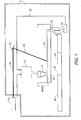
- FIG. 1 shows a remote laser manufacturing system 1 for preparing in a remote location high density pellets containing highly radioactive elements, in accordance with certain embodiments of the invention.
- FIG. 1 includes a shielded enclosure 5 and a laser 10. Positioned within the shielded enclosure 5 are a hopper 12 and a distributer 14. A dry feed composition including highly radioactive elements and matrix is loaded into the hopper 12 and is then fed into the distributer 14. The distributer 14 releases and distributes the feed composition onto a tray 16 to form a first layer 18 of feed composition.
- the laser 10 emits a beam 20 which is directed toward a mirror 22 positioned within the shielded enclosure 5.
- the beam 20 is reflected by the mirror 22 and directed toward the first layer 18 of feed composition. As a result, the beam 20 sinters the first layer 18.
- the first layer 18 can be sintered in patterns.
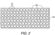
- FIG. 2 shows a top view of a tray 16 having a plurality of sintered pellet shapes 24 formed by directing the beam 20 onto the first layer 18 of the feed composition.
- FIG. 1 shows that the sintered pellet shapes 24 (shown in FIG. 2 ) can be passed from the tray 16 through a screen 28 to separate the sintered pellet shapes 24 from unsintered feed composition.
- the unsintered feed composition can be collected in a holder and powder miller 30 and transported through a return line 32 and loaded (e.g., recycled) into the hopper 12.
- the sintered pellet shapes 24 can be transported to a grinder 34 to grind the sintered pellet shapes to a pre-specified diameter, to a cleaner 36 to remove residual feed composition therefrom, and then to a fuel rod loader 38 for loading the sintered pellet shapes 24 into a nuclear reactor (not shown).
Landscapes
- Engineering & Computer Science (AREA)
- Chemical & Material Sciences (AREA)
- Physics & Mathematics (AREA)
- Manufacturing & Machinery (AREA)
- Ceramic Engineering (AREA)
- Materials Engineering (AREA)
- General Engineering & Computer Science (AREA)
- High Energy & Nuclear Physics (AREA)
- Plasma & Fusion (AREA)
- Structural Engineering (AREA)
- Organic Chemistry (AREA)
- Optics & Photonics (AREA)
- Environmental & Geological Engineering (AREA)
- Mechanical Engineering (AREA)
- Compositions Of Oxide Ceramics (AREA)
- Inorganic Compounds Of Heavy Metals (AREA)
- Monitoring And Testing Of Nuclear Reactors (AREA)
Description
- This invention pertains to laser systems and methods which are useful, in particular, for the remote preparation of high density pellets which include a ceramic matrix material and highly radioactive elements.
- High level nuclear fuel waste is generated as a result of the reprocessing of used nuclear fuel from the operation of commercial nuclear power plants throughout the world. In order to dispose of this waste, it is necessary to recover and reduce the long lived highly radioactive elements contained therein. The long lived highly radioactive elements can include Americium (Am), Curium (Cm), Plutonium (Pu), Neptunium (Np), Protactinium (Pa), Californium (Cf), Uranium (U), Thorium (Th), and certain fission products, such as Technetium (Tc)-99, Iodine (I)-129, Zirconium (Zr)-93, Selenium (Se)-79 and Tin (Sn)-126. U can be contaminated with U-232 and/or U-234 and Th can be contaminated with Th-228. Certain isotopes of these nuclear fuel elements have very high and penetrating radiation fields. The radiation fields increase even further when irradiated Th and U are recycled due to the build-up of Th-228, U-232 and associated decay products. In addition, further contamination with radioactive fission products typically formed in a fission reactor may occur. Reducing the radioactivity of the high level waste can be carried out by forming pellets containing oxide, silicide, nitride, or carbide of these highly radioactive elements with a thorium or uranium or zirconium oxide, silicide, nitride or carbide matrix, and then exposing the pellets to an intense neutron spectrum of a nuclear reactor which will ultimately reduce the content of these radioactive elements by transmutation into stable fission products. The high and penetrating radiation fields of the highly radioactive elements require that the manufacturing process be accomplished remotely in a heavily-shielded location.
- Based on operational requirements for a commercial nuclear plant, the fuel pellets should have a high density (e.g., greater than 85% smeared theoretical density) in order to provide satisfactory performance. The complex pelletizing and sintering equipment and industrial pellet manufacturing techniques that are known in the art for producing high density fuel are not suitable for use in a heavily shielded, remotely operated manufacturing cell.
- Thus, there is a need in the art to design and develop systems and processes for sintering and pelletizing high density, e.g., greater than 85% smeared theoretical density, highly radioactive element-containing pellets in a heavily shielded, remotely operated area. Further, it is desired that the sintering and pelletizing processes can be carried out from a remote location, e.g., inside the heavily shielded area, using equipment which requires minimal maintenance throughout its lifetime and allows for straightforward process automation.
-
JPH11183677 - The present invention consists in a laser sintering system according to claim 1 and in a laser sintering method according to claim 11. In one aspect, this invention provides a laser sintering system to remotely prepare a fuel pellet for use in a nuclear reactor. The system includes a feed composition including at least one highly radioactive element in a form selected from the group consisting of oxide, silicide, nitride, carbide and mixtures thereof, and a ceramic matrix material. The feed composition is in a dry form. The system also includes a shielded enclosure having a flat surface disposed therein to receive and hold a layer of the feed composition. The system further includes at least one laser structured to direct a beam to sinter at least one pattern in the layer of the feed composition and to form a pellet. The controls for the at least one laser are positioned outside of the shielded enclosure. The at least one pattern corresponds to a pre-determined shape of the pellet.
- The shielded enclosure can have a temperature in a range from 1000°C to 2000°C.
- The beam of the at least one laser can be directed by a reflective device positioned above the flat surface.
- The at least one highly radioactive element is selected from the group consisting of Americium, Curium, Plutonium, Neptunium, Protactinium, Californium, Uranium, Thorium, fission products found in reprocessed nuclear fuel material, and mixtures thereof. The Uranium can be contaminated with U-232 and/or U-234 and the Thorium can be contaminated with Th-228. The fission products can be selected from the group consisting of Cesium, Strontium, Technetium, Ruthenium, and mixtures thereof. The ceramic matrix material can be selected from the group consisting of oxide, nitride, carbide, silicide, and mixtures thereof. Further, the ceramic matrix material can be selected from the group consisting of oxide, nitride, carbide, and silicide of Uranium, Thorium, Zirconium, Protactinium, Plutonium, and mixtures thereof. The pellet can have a density of about 85% or greater theoretical density. Also, the feed composition can be in the form of a powder.
- Further, the layer can have a substantially uniform thickness in a range from 5 to 100 microns.
- Furthermore, the at least one pattern can be in the shape of a circle to produce a cylindrical pellet.
- In certain embodiments, the matrix material is selected from the group consisting of Thorium Oxide, Zirconium Oxide, Uranium Oxide, and mixtures thereof.
- In another aspect, this invention provides a laser sintering method for remotely preparing a fuel pellet for use in a nuclear reactor. The method includes preparing a feed composition in a dry form including at least one highly radioactive element in a form selected from the group consisting of oxide, silicide, nitride, carbide and mixtures thereof, and a ceramic matrix material. The method also includes obtaining a shielded enclosure having a flat surface disposed therein, distributing the feed composition onto the flat surface forming a first layer, employing at least one laser and directing a beam of the at least one laser toward the first layer of the feed composition wherein the at least one laser is operated from controls positioned outside of the shielded enclosure, and forming at least one pattern within the first layer, wherein the shape of the at least one pattern corresponds to a pre-determined shape of the pellet.
- In certain embodiments, the method described above is repeated for distributing and sintering a second layer onto the first layer for preparing the pellet having an increased height. Moreover, the above-described method can be repeated a plurality of times for sequentially forming a plurality of layers onto the first layer until a pre-determined height of the pellet is achieved. Each of the plurality of layers can have a thickness in a range from 5 to 100 microns.
- A further understanding of the invention can be gained from the following description of the preferred embodiments when read in conjunction with the accompanying drawings in which:
-
FIG. 1 shows a schematic of a remote laser manufacture process for producing pellets containing radioactive elements in accordance with certain embodiments of the invention. -
FIG. 2 shows a schematic of a top view of a feed composition tray having sintered pellet shapes and unsintered powder in accordance with certain embodiments of the invention. - The invention relates to remotely operated laser sintering systems and methods for manufacturing fuel pellets containing highly radioactive elements. The highly radioactive elements can originate from used or spent nuclear fuel. For example, long half-life, highly radioactive elements can be recovered from materials obtained from the reprocessing of used nuclear fuels and can include fission product contaminants. In the invention, these radioactive elements are combined with a ceramic matrix material to form the pellets. In general, the resultant pellets can be used in a fuel rod of an operating nuclear reactor, such as a pressurized water nuclear reactor, boiling water reactor, heavy water reactor, reduced moderation reactor or fast reactor.
- The nuclear fuel generally includes highly radioactive and long half-life elements. These elements can be in the form of oxide, silicide, nitride, carbide and mixtures thereof. The highly radioactive and long half-life elements can include transmutation products and fission products. As used herein, the term "transmutation products" refers to materials formed in a reactor due to the absorption of neutrons by isotopes. As used herein, the term "fission products" refers to materials formed by the fissioning of uranium atoms. The radioactive transmutation products can include Americium (Am), Curium (Cm), Plutonium (Pu), Neptunium (Np), Protactinium (Pa), Californium (Cf), Uranium (U) and Thorium (Th) . In certain embodiments, the U can be contaminated with U-232 and/or U-234 and the Th can be contaminated with Th-228. The fission products can include Cesium (Cs), Strontium (Sr), Technetium (Tc), Ruthenium (Ru), and mixtures thereof. The fission products can include Tc-99, Iodine (I)-129, Zirconium (Zr)-93, Selenium (Se)-79 and Tin (Sn)-126.
- In certain embodiments U contaminated with U-232, and Th contaminated with Th-228 is present.
- The highly radioactive elements can also be potentially radiotoxic.
- The ceramic matrix material can include oxide, nitride, silicide, carbide and mixtures thereof. Further, the ceramic matrix material can include one or more of oxide, nitride, silicide and carbide of fertile or inert materials. In certain embodiments, the ceramic matrix material includes oxide, nitride, silicide or carbide of U, Th, Zirconium (Zr), Pa, Pu and mixtures thereof. In certain embodiments, the matrix material can include Th Oxide, U Oxide, Zr Oxide and mixtures thereof.
- At least one highly radioactive element is combined with the ceramic matrix material to form a feed composition. The feed composition is in a dry form, such as but not limited to a powder. The feed composition can also include other materials and additives that are known in the art for producing pellets for use in a nuclear reactor fuel rod.
- The feed composition is distributed on a flat surface, such as a tray, to form a bed or layer thereon. The feed composition is distributed substantially uniformly on the flat surface. Further, it is favourable that placement of the feed composition is such that it does not form a mound or pile on the flat surface. The thickness of the bed or layer can vary. In certain embodiments, the layer is a thin layer and the thickness can be in a range from 5 to 100 microns.
- Due to the high radioactivity, and potential radiotoxicity, of elements used in the invention, the flat surface or tray is positioned in a shielded enclosure, such as a heavily-shielded chamber. The shielded enclosure is typically maintained at an elevated temperature, e.g., above ambient or room temperature. In certain embodiments, the temperature of the shielded enclosure is in a range from about 1000°C to about 2000°C.
- One or more lasers are employed to sinter the feed composition. The laser(s) can include a wide variety of products known in the art and commercially available. The one or more lasers and/or the control motor(s) associated therewith can be located outside of the shielded area such that the sintering process can be controlled remotely. Thus, the control(s) and/or laser(s) can be positioned and operated from outside of the shielded enclosure while the laser beam(s) is operable inside of the shielded enclosure. This design and configuration is advantageous due to the radioactivity, and potential radiotoxicity, of the feed composition. The highly radioactive elements that are present in the feed composition have high and penetrating radiation fields and therefore, conventional manufacturing techniques are not suitable.
- In accordance with the present invention, the laser beam(s) is directed by a reflective device, a fiber optic device, or a similar device. The device can be a mirror, such as a servo-controlled mirror, or fiber optic cable. The reflective device or the like is located in the shielded enclosure and positioned above the bed or layer of feed composition. The direction of the laser beam(s) can be positioned using x-y controller motors from the laser(s) located outside of the shielded enclosure. The laser beam(s) is directed toward and is in contact with at least a portion of the bed or layer of feed composition on the flat surface. In directing the beam(s), the beam(s) is handled such that one or more patterns are formed in the feed composition. The shape of the patterns corresponds to the intended or desired shape of the resultant pellet. For example, if a cylindrical pellet is intended, the beam(s) is directed to form one or more circular patterns in the layer or bed of feed composition. The sintered, patterned layer of feed composition can form a pellet. In other arrangements, the sintered, patterned layer of feed composition can form a base for a pellet, and additional layers can be added onto the base.
- In certain embodiments, following laser sintering of a first layer or bed of feed composition to form a pattern for a pellet, a second layer of feed composition may be applied to the sintered first layer to increase the height of the pellet. The laser beam(s) is directed to the second layer which is distributed over, e.g., on top of, the first layer (or base layer). This second layer is sintered in substantially the same pattern as the first layer such that the second layer is added to the first layer, e.g., deposited on top of the first layer, to increase the overall height of the pellet. If the desired or pre-specified height of the pellet is achieved following sintering of the second layer of feed composition, the process is ended. If, however, the desired height of the resultant pellet after sintering two layers of feed composition is not achieved, a third layer and optionally subsequent or additional layers may be added to the feed composition bed on the flat surface and sintered to further increase the height of the pellet until the desired height of the pellet is achieved.
- As previously described for the first or base bed or layer of feed composition, the second, third and subsequent layers of feed composition are each typically a thin layer which can vary in thickness. In certain embodiments, each of the layers can have a thickness in a range from 5 to 100 microns. Further, each of the second, third and subsequent layers is sintered in substantially the same shape or pattern, e.g., a circle, as the first layer in order to form a substantially uniform pellet having a corresponding pattern or shape, e.g., a cylinder.
- The desired height of the pellet can vary. In certain embodiments, the height of the pellet is from 1 to 500 mm.
- The desired diameter of the pellet can also vary. In certain arrangements, the diameter of the pellet is from 1 to 30 mm or from 5 to 10 mm.
- In order for the resulting pellets to be useful in an operating nuclear reactor, the pellets are manufactured to have a high density. As used herein and the claims, the term "high density" refers to about 85% or greater theoretical density.
-
FIG. 1 shows a remote laser manufacturing system 1 for preparing in a remote location high density pellets containing highly radioactive elements, in accordance with certain embodiments of the invention.FIG. 1 includes a shieldedenclosure 5 and alaser 10. Positioned within the shieldedenclosure 5 are ahopper 12 and adistributer 14. A dry feed composition including highly radioactive elements and matrix is loaded into thehopper 12 and is then fed into thedistributer 14. The distributer 14 releases and distributes the feed composition onto atray 16 to form afirst layer 18 of feed composition. Thelaser 10 emits abeam 20 which is directed toward amirror 22 positioned within the shieldedenclosure 5. Thebeam 20 is reflected by themirror 22 and directed toward thefirst layer 18 of feed composition. As a result, thebeam 20 sinters thefirst layer 18. Thefirst layer 18 can be sintered in patterns. -
FIG. 2 shows a top view of atray 16 having a plurality of sintered pellet shapes 24 formed by directing thebeam 20 onto thefirst layer 18 of the feed composition. Thearea 26, outside the circumference of the sintered pellet shapes 24, is unsintered feed composition. - Further,
FIG. 1 shows that the sintered pellet shapes 24 (shown inFIG. 2 ) can be passed from thetray 16 through ascreen 28 to separate the sintered pellet shapes 24 from unsintered feed composition. The unsintered feed composition can be collected in a holder andpowder miller 30 and transported through areturn line 32 and loaded (e.g., recycled) into thehopper 12. The sintered pellet shapes 24 can be transported to agrinder 34 to grind the sintered pellet shapes to a pre-specified diameter, to a cleaner 36 to remove residual feed composition therefrom, and then to afuel rod loader 38 for loading the sintered pellet shapes 24 into a nuclear reactor (not shown). - While specific embodiments of the invention have been described in detail, it will be appreciated by those skilled in the art that various modifications and alternatives to those details could be developed in light of the overall teachings of the disclosure. Accordingly, the particular embodiments disclosed are meant to be illustrative only and not limiting as to the scope of the invention which is to be given the full breadth of the appended claims.
Claims (15)
- A laser sintering system (1) arranged to prepare a fuel pellet (24) for use in a nuclear reactor, comprising:a shielded enclosure (5);a powder feed composition, which comprises:at least one radioactive element selected from the group consisting of Americium, Curium, Plutonium, Neptunium, Protactinium, Californium, Uranium, Thorium, Cesium, Strontium, Technetium, Ruthenium and mixtures thereof in a form selected from the group consisting of oxide, silicide, nitride, carbide and mixtures thereof; anda ceramic matrix material;at least one laser (10) positioned outside the shielded enclosure (5) and structured to emit a laser beam (20) into the shielded enclosure to sinter at least one pattern in a layer (18) of the powder feed composition; anda plurality of components positioned inside the shielded enclosure (5), which comprise:a flat surface (16) structured to hold the layer (18) of the powder feed composition;a distributer structured to receive the powder feed composition and substantially uniformly distribute the powder feed composition onto the flat surface (16) in a form of the layer (18); anda reflective device (22) structured to direct the laser beam (20) toward the flat surface (16) such that the laser beam (20) contacts at least a portion of the layer (18) of the powder feed composition, to sinter the layer (18) of the powder feed composition to form the fuel pellet (24).
- The system (1) of claim 1, wherein the Uranium comprises U-232, and wherein the Thorium-comprises Th-228.
- The system (1) of claim 1, wherein the at least one radioactive element comprises a first element selected from the group consisting of Americium, Curium, Plutonium, Neptunium, Protactinium, Californium, Uranium, Thorium and mixtures thereof, and a second element selected from the group consisting of Cesium, Strontium, Technetium, Ruthenium and mixtures thereof.
- The system (1) of claim 1, wherein the matrix material is selected from the group consisting of oxide, nitride, carbide, and silicide of Uranium, Thorium, Zirconium, Protactinium, Plutonium and mixtures thereof.
- The system (1) of claim 1, wherein the reflective device (22) is a reflective mirror positioned above the flat surface (16) for directing the laser beam (20) toward the layer (18) of the powder feed composition.
- The system (1) of claim 1, wherein the layer (18) is substantially uniform and has a thickness in a range from 5 to 100 microns.
- The system (1) of claim 1, wherein the laser beam (20) is arranged to sinter at least one pattern for each of a second layer, a third layer and subsequent layers of the powder feed composition, the at least one pattern being substantially the same as the at least one pattern in the layer (18) to form a substantially uniform pellet (24) having a corresponding shape.
- The system (1) of claim 7, wherein each of the at least one pattern is a circle and the corresponding shape is a cylinder.
- The system (1) of claim 1, wherein the matrix material is Thorium Oxide.
- The system (1) of claim 1, wherein the enclosure (5) is arranged to have in use a temperature in a range of from 1000°C to 2000°C.
- A laser sintering method for preparing a fuel pellet (24) for use in a nuclear reactor, comprising:preparing a powder feed composition, which comprises:at least one radioactive element in a form selected from the group consisting of oxide, silicide, nitride, carbide, and mixtures thereof; anda ceramic matrix material;obtaining a shielded enclosure (5);employing at least one laser (10) for emitting a laser beam (20) inside the shielded enclosure (5);positioning the at least one laser (10) outside of the shielded enclosure for remotely operating and controlling the laser beam (20);positioning inside the shielded enclosure a flat surface for receiving the layer (18) of the powder feed composition;positioning inside the shielded enclosure a distributer for receiving and substantially uniformly distributing the powder feed composition onto the flat surface in the form of the layer (18);positioning a reflective device (22) inside the shielded enclosure for directing the laser beam (20) in the shielded enclosure (5) toward the flat surface (16);contacting at least a portion of the layer (18) of the powder feed composition with the laser beam (20);sintering the layer (18) of the powder feed composition; andforming at least one pattern within the layer (18).
- The method of claim 11, wherein the method is repeated for distributing and sintering a second layer onto the first layer (18) forming a pellet (24) having an increased height.
- The method of claim 12, wherein the method is repeated a plurality of times sequentially forming a plurality of layers.
- The method of claim 13, wherein each of the plurality of layers has a thickness in a range of from 5 to 100 microns.
- The method of claim 14, wherein the pellet (24) has a height of from 1 to 500 mm.
Applications Claiming Priority (2)
| Application Number | Priority Date | Filing Date | Title |
|---|---|---|---|
| US13/744,711 US9646729B2 (en) | 2013-01-18 | 2013-01-18 | Laser sintering systems and methods for remote manufacture of high density pellets containing highly radioactive elements |
| PCT/US2013/076334 WO2014133656A2 (en) | 2013-01-18 | 2013-12-19 | Laser sintering systems and methods for remote manufacture of high density pellets containing highly radioactive elements |
Publications (3)
| Publication Number | Publication Date |
|---|---|
| EP2946392A2 EP2946392A2 (en) | 2015-11-25 |
| EP2946392A4 EP2946392A4 (en) | 2016-08-17 |
| EP2946392B1 true EP2946392B1 (en) | 2018-07-18 |
Family
ID=51207109
Family Applications (1)
| Application Number | Title | Priority Date | Filing Date |
|---|---|---|---|
| EP13876288.5A Not-in-force EP2946392B1 (en) | 2013-01-18 | 2013-12-19 | Laser sintering systems and methods for remote manufacture of high density pellets containing highly radioactive elements |
Country Status (7)
| Country | Link |
|---|---|
| US (1) | US9646729B2 (en) |
| EP (1) | EP2946392B1 (en) |
| JP (1) | JP6348122B2 (en) |
| KR (1) | KR20150107848A (en) |
| CN (2) | CN104919536A (en) |
| ES (1) | ES2690833T3 (en) |
| WO (1) | WO2014133656A2 (en) |
Families Citing this family (8)
| Publication number | Priority date | Publication date | Assignee | Title |
|---|---|---|---|---|
| US9786391B2 (en) * | 2015-02-19 | 2017-10-10 | X-Energy, Llc | Nuclear fuel pebble and method of manufacturing the same |
| US10522255B2 (en) | 2015-02-19 | 2019-12-31 | X-Energy, Llc | Nuclear fuel pebble and method of manufacturing the same |
| US20160368207A1 (en) * | 2015-06-19 | 2016-12-22 | Elwha Llc | Printing systems and related methods |
| EP3287213A1 (en) | 2016-08-23 | 2018-02-28 | Paul Scherrer Institut | Aqueous additive production method for the fabrication of ceramic and/or metallic bodies |
| US10022795B1 (en) * | 2017-01-13 | 2018-07-17 | General Electric Company | Large scale additive machine |
| US10022794B1 (en) | 2017-01-13 | 2018-07-17 | General Electric Company | Additive manufacturing using a mobile build volume |
| FR3114770B1 (en) * | 2020-10-05 | 2023-01-20 | Framatome Sa | Method for manufacturing a coated nuclear reactor component provided with a label |
| CN114188053B (en) * | 2021-12-06 | 2024-11-08 | 中国核电工程有限公司 | Automatic fuel rod box loading device |
Family Cites Families (47)
| Publication number | Priority date | Publication date | Assignee | Title |
|---|---|---|---|---|
| AT366845B (en) * | 1977-05-24 | 1982-05-10 | Oesterr Forsch Seibersdorf | METHOD FOR PRODUCING SPHERICAL FUEL PARTICLES |
| JPS54114698A (en) * | 1978-02-28 | 1979-09-06 | Mitsubishi Atom Power Ind Inc | Preparing carbide fuel pellet for fast neutron reactor |
| JPS54121442A (en) * | 1978-03-13 | 1979-09-20 | Power Reactor & Nuclear Fuel Dev Corp | Microwave heating device for radioactive material |
| US4436677A (en) * | 1982-08-02 | 1984-03-13 | Westinghouse Electric Corp. | Nuclear fuel fabrication process |
| CN1005732B (en) * | 1985-04-01 | 1989-11-08 | 上海灯泡厂 | Tungsten-cerium electrode material and its preparation process and application |
| US4871479A (en) | 1986-03-25 | 1989-10-03 | Comurhex Societe Pour La Conversion De L'uranium En Metal Et Hexafluorure | Process for producing sintered mixed oxides which are soluble in nitric acid from solutions of nitrates |
| JPH0636065B2 (en) * | 1987-10-01 | 1994-05-11 | 原子燃料工業株式会社 | Sintering furnace for oxide nuclear fuel |
| US5431967A (en) | 1989-09-05 | 1995-07-11 | Board Of Regents, The University Of Texas System | Selective laser sintering using nanocomposite materials |
| JP2798281B2 (en) * | 1989-10-31 | 1998-09-17 | 龍三 渡辺 | Particle array laser sintering method and apparatus |
| JPH0493694A (en) * | 1990-08-03 | 1992-03-26 | Toshiba Corp | Transuranium element quenching fuel and fuel assembly |
| US5227608A (en) * | 1992-07-31 | 1993-07-13 | Matsuhita Electric Industrial Co., Ltd. | Laser ablation apparatus |
| US5585020A (en) * | 1994-11-03 | 1996-12-17 | Becker; Michael F. | Process for the production of nanoparticles |
| FR2744557B1 (en) * | 1996-02-07 | 1998-02-27 | Commissariat Energie Atomique | COMPOSITE NUCLEAR FUEL MATERIAL AND METHOD FOR MANUFACTURING THE MATERIAL |
| FR2752325B1 (en) * | 1996-08-06 | 1998-10-09 | Cogema | METHOD AND DEVICE FOR DEDUCTING NUCLEAR FUEL PELLETS USING A LASER BEAM |
| US5837330A (en) * | 1997-08-28 | 1998-11-17 | Seagate Technology, Inc. | Dual fiber optic laser texturing |
| KR100285168B1 (en) * | 1997-12-02 | 2001-03-15 | 장인순 | Manufacturing method of carbide, boride or nitride coated fuel using high temperature and high pressure combustion synthesis |
| US20050120715A1 (en) * | 1997-12-23 | 2005-06-09 | Christion School Of Technology Charitable Foundation Trust | Heat energy recapture and recycle and its new applications |
| US6132667A (en) * | 1999-02-08 | 2000-10-17 | 3D Systems, Inc. | Stereolithographic method and apparatus with enhanced control of prescribed stimulation production and application |
| US6126884A (en) * | 1999-02-08 | 2000-10-03 | 3D Systems, Inc. | Stereolithographic method and apparatus with enhanced control of prescribed stimulation production and application |
| US6241934B1 (en) * | 1999-02-08 | 2001-06-05 | 3D Systems, Inc. | Stereolithographic method and apparatus with enhanced control of prescribed stimulation production and application |
| JP2000329883A (en) * | 1999-05-19 | 2000-11-30 | Toshiba Corp | Fuel assemblies, fission product assemblies and reactor cores |
| US6372678B1 (en) * | 2000-09-28 | 2002-04-16 | Fairmount Minerals, Ltd | Proppant composition for gas and oil well fracturing |
| JP3446733B2 (en) * | 2000-10-05 | 2003-09-16 | 松下電工株式会社 | Method and apparatus for manufacturing three-dimensional shaped object |
| US20020107510A1 (en) * | 2001-02-05 | 2002-08-08 | Andrews Robert R. | Laser apparatus useful for myocardial revascularization |
| DE10249355B4 (en) | 2002-10-23 | 2005-08-04 | Framatome Anp Gmbh | Fuel pellet for a nuclear reactor and process for its production |
| JP2004330280A (en) * | 2003-05-12 | 2004-11-25 | Ishikawajima Harima Heavy Ind Co Ltd | Heat-resistant ceramic core having three-dimensional shape and method of manufacturing cast product thereof |
| US8213007B2 (en) * | 2003-05-27 | 2012-07-03 | Optotrace Technologies, Inc. | Spectrally sensing chemical and biological substances |
| CN100557720C (en) * | 2003-09-29 | 2009-11-04 | 联邦国家统一企业A·A·博奇瓦尔全俄无机材料研究院 | Method for producing ceramic nuclear fuel pellets, and device and container for implementing said method |
| FR2860638A1 (en) * | 2003-10-06 | 2005-04-08 | Commissariat Energie Atomique | PROCESS FOR MANUFACTURING PELLETS OF NUCLEAR FUEL BASED ON MIXED (U, PU) O2 OR (U, TH) O2 OXIDE FUEL |
| US7291271B2 (en) * | 2003-12-09 | 2007-11-06 | Separation Design Group, Llc | Meso-frequency traveling wave electro-kinetic continuous adsorption system |
| US20050263934A1 (en) | 2004-05-28 | 2005-12-01 | 3D Systems, Inc. | Single side feed parked powder wave heating with wave flattener |
| US7419887B1 (en) * | 2004-07-26 | 2008-09-02 | Quick Nathaniel R | Laser assisted nano deposition |
| US7569174B2 (en) * | 2004-12-07 | 2009-08-04 | 3D Systems, Inc. | Controlled densification of fusible powders in laser sintering |
| DE102005015870B3 (en) | 2005-04-06 | 2006-10-26 | Eos Gmbh Electro Optical Systems | Device and method for producing a three-dimensional object |
| FR2892223B1 (en) * | 2005-10-18 | 2011-05-27 | Cogema | DEVICE FOR MANUFACTURING NUCLEAR COMBUSTIBLE PELLETS AND MANUFACTURING METHOD USING SUCH A DEVICE |
| RU2450379C2 (en) * | 2006-06-15 | 2012-05-10 | Бельгонюклеэр Са | Devices and methods to prevent criticality in production of nuclear fuel |
| CA2681824A1 (en) * | 2007-04-04 | 2008-12-24 | The Regents Of The University Of California | Laser activated micro accelerator platform |
| CN101364450B (en) * | 2008-07-01 | 2012-06-27 | 上海大学 | Method implementing nuclear fusion reaction based on sound cavitation effect |
| US7700032B1 (en) * | 2008-07-14 | 2010-04-20 | The United States Of America As Represented By The Secretary Of The Navy | Formation of microspheres through laser irradiation of a surface |
| DE102008038988B3 (en) * | 2008-08-13 | 2009-09-17 | Kraussmaffei Technologies Gmbh | Combined plastics die cutter and trimmer has robotic laser arm directed between moving upper and fixed lower tools |
| JP5252586B2 (en) * | 2009-04-15 | 2013-07-31 | ウシオ電機株式会社 | Laser drive light source |
| FR2949598B1 (en) * | 2009-09-02 | 2013-03-29 | Commissariat Energie Atomique | PROCESS FOR PREPARING A POROUS NUCLEAR FUEL BASED ON AT LEAST ONE MINOR ACTINIDE |
| CN102072894B (en) * | 2009-11-25 | 2013-05-01 | 欧普图斯(苏州)光学纳米科技有限公司 | Detection of Chemical and Biochemical Impurities Using Nanostructure-Based Spectroscopic Detection |
| WO2011082102A1 (en) * | 2009-12-31 | 2011-07-07 | Oxane Materials, Inc. | Ceramic particles with controlled pore and/or microsphere placement and/or size and method of making same |
| US8992815B2 (en) * | 2010-02-10 | 2015-03-31 | Imra America, Inc. | Production of organic compound nanoparticles with high repetition rate ultrafast pulsed laser ablation in liquids |
| CN201685457U (en) * | 2010-06-02 | 2010-12-29 | 研能科技股份有限公司 | Three-dimensional forming mechanism |
| EP2666612B1 (en) * | 2012-05-25 | 2018-11-28 | MTU Aero Engines AG | Method and device for imaging at least one three-dimensional component |
-
2013
- 2013-01-18 US US13/744,711 patent/US9646729B2/en not_active Expired - Fee Related
- 2013-12-19 WO PCT/US2013/076334 patent/WO2014133656A2/en not_active Ceased
- 2013-12-19 EP EP13876288.5A patent/EP2946392B1/en not_active Not-in-force
- 2013-12-19 CN CN201380070604.7A patent/CN104919536A/en active Pending
- 2013-12-19 JP JP2015553740A patent/JP6348122B2/en not_active Expired - Fee Related
- 2013-12-19 CN CN201910301844.2A patent/CN110066161A/en active Pending
- 2013-12-19 KR KR1020157022126A patent/KR20150107848A/en not_active Ceased
- 2013-12-19 ES ES13876288.5T patent/ES2690833T3/en active Active
Non-Patent Citations (1)
| Title |
|---|
| None * |
Also Published As
| Publication number | Publication date |
|---|---|
| WO2014133656A3 (en) | 2014-11-27 |
| ES2690833T3 (en) | 2018-11-22 |
| EP2946392A2 (en) | 2015-11-25 |
| EP2946392A4 (en) | 2016-08-17 |
| JP6348122B2 (en) | 2018-06-27 |
| KR20150107848A (en) | 2015-09-23 |
| US20140203460A1 (en) | 2014-07-24 |
| WO2014133656A2 (en) | 2014-09-04 |
| US9646729B2 (en) | 2017-05-09 |
| CN110066161A (en) | 2019-07-30 |
| JP2016503903A (en) | 2016-02-08 |
| CN104919536A (en) | 2015-09-16 |
Similar Documents
| Publication | Publication Date | Title |
|---|---|---|
| US9646729B2 (en) | Laser sintering systems and methods for remote manufacture of high density pellets containing highly radioactive elements | |
| Konings et al. | The EFTTRA-T4 experiment on americium transmutation | |
| RU2313146C2 (en) | System and method for destroying radioactive waste | |
| US20200321134A1 (en) | Fuel pellets having a heterogeneous composition and related methods | |
| Haas et al. | Mixed-oxide fuel fabrication technology and experience at the Belgonucléaire and CFCa plants and further developments for the MELOX plant | |
| Yoshimochi et al. | Fabrication technology for MOX fuel containing AmO2 by an in-cell remote process | |
| US11742096B2 (en) | Aqueous additive production method for the fabrication of metallic bodies | |
| Verfondern | High-quality Thorium TRISO fuel performance in HTGRs | |
| Konings et al. | Fuels and targets for transmutation | |
| Roepenack et al. | Development of thermal plutonium recycling | |
| Mukerjee et al. | Fabrication technologies for ThO2-based fuel | |
| Somers et al. | Fabrication Routes for Yttria‐Stabilized Zirconia Suitable for the Production of Minor Actinide Transmutation Targets | |
| Nagarajan et al. | Sol-gel processes for nuclear fuel fabrication | |
| Knauer et al. | Californium-252 production and neutron source fabrication | |
| Hayes | Metallic Fuels for Fast Reactors | |
| JP2025040577A (en) | Transmutation method for minor actinides | |
| Kutty et al. | Development and Microstructural Characterization of ThO | |
| Meldner | Inertial confinement fusion and long-term nuclear waste management | |
| Schenk et al. | Experience with the use of recycle plutonium in mixed-oxide fuel in light water reactors in the Federal Republic of Germany | |
| Readey | Argonne, Illinois | |
| Lamb et al. | Curium-244 heat source fabrication | |
| Fernandez et al. | Fuels and targets for incineration and transmutation of actinides: the ITU programme | |
| Ekberg et al. | Studies of decay power for KBS part 1. Literature review part 2. Calculations | |
| Guerin et al. | Transmutation of minor actinides in PWRs: preparation of the ACTINEAU experiment | |
| Yamada et al. | Conceptual Design of an Engineering-scale Plant applying the Simplified MA-bearing Fuel Fabrication Process |
Legal Events
| Date | Code | Title | Description |
|---|---|---|---|
| PUAI | Public reference made under article 153(3) epc to a published international application that has entered the european phase |
Free format text: ORIGINAL CODE: 0009012 |
|
| 17P | Request for examination filed |
Effective date: 20150623 |
|
| AK | Designated contracting states |
Kind code of ref document: A2 Designated state(s): AL AT BE BG CH CY CZ DE DK EE ES FI FR GB GR HR HU IE IS IT LI LT LU LV MC MK MT NL NO PL PT RO RS SE SI SK SM TR |
|
| AX | Request for extension of the european patent |
Extension state: BA ME |
|
| DAX | Request for extension of the european patent (deleted) | ||
| A4 | Supplementary search report drawn up and despatched |
Effective date: 20160719 |
|
| RIC1 | Information provided on ipc code assigned before grant |
Ipc: C04B 35/01 20060101ALI20160713BHEP Ipc: G21F 9/32 20060101AFI20160713BHEP Ipc: G21C 3/04 20060101ALI20160713BHEP Ipc: G21C 21/02 20060101ALI20160713BHEP Ipc: B29C 67/00 20060101ALI20160713BHEP |
|
| 17Q | First examination report despatched |
Effective date: 20170710 |
|
| GRAP | Despatch of communication of intention to grant a patent |
Free format text: ORIGINAL CODE: EPIDOSNIGR1 |
|
| INTG | Intention to grant announced |
Effective date: 20180410 |
|
| RAP1 | Party data changed (applicant data changed or rights of an application transferred) |
Owner name: WESTINGHOUSE ELECTRIC COMPANY LLC |
|
| GRAS | Grant fee paid |
Free format text: ORIGINAL CODE: EPIDOSNIGR3 |
|
| GRAA | (expected) grant |
Free format text: ORIGINAL CODE: 0009210 |
|
| AK | Designated contracting states |
Kind code of ref document: B1 Designated state(s): AL AT BE BG CH CY CZ DE DK EE ES FI FR GB GR HR HU IE IS IT LI LT LU LV MC MK MT NL NO PL PT RO RS SE SI SK SM TR |
|
| REG | Reference to a national code |
Ref country code: GB Ref legal event code: FG4D |
|
| REG | Reference to a national code |
Ref country code: FR Ref legal event code: PLFP Year of fee payment: 6 |
|
| REG | Reference to a national code |
Ref country code: CH Ref legal event code: EP |
|
| REG | Reference to a national code |
Ref country code: IE Ref legal event code: FG4D |
|
| REG | Reference to a national code |
Ref country code: DE Ref legal event code: R096 Ref document number: 602013040654 Country of ref document: DE |
|
| REG | Reference to a national code |
Ref country code: AT Ref legal event code: REF Ref document number: 1020225 Country of ref document: AT Kind code of ref document: T Effective date: 20180815 |
|
| REG | Reference to a national code |
Ref country code: SE Ref legal event code: TRGR |
|
| REG | Reference to a national code |
Ref country code: NL Ref legal event code: MP Effective date: 20180718 |
|
| REG | Reference to a national code |
Ref country code: ES Ref legal event code: FG2A Ref document number: 2690833 Country of ref document: ES Kind code of ref document: T3 Effective date: 20181122 |
|
| REG | Reference to a national code |
Ref country code: LT Ref legal event code: MG4D |
|
| REG | Reference to a national code |
Ref country code: AT Ref legal event code: MK05 Ref document number: 1020225 Country of ref document: AT Kind code of ref document: T Effective date: 20180718 |
|
| PG25 | Lapsed in a contracting state [announced via postgrant information from national office to epo] |
Ref country code: NL Free format text: LAPSE BECAUSE OF FAILURE TO SUBMIT A TRANSLATION OF THE DESCRIPTION OR TO PAY THE FEE WITHIN THE PRESCRIBED TIME-LIMIT Effective date: 20180718 |
|
| PG25 | Lapsed in a contracting state [announced via postgrant information from national office to epo] |
Ref country code: AT Free format text: LAPSE BECAUSE OF FAILURE TO SUBMIT A TRANSLATION OF THE DESCRIPTION OR TO PAY THE FEE WITHIN THE PRESCRIBED TIME-LIMIT Effective date: 20180718 Ref country code: NO Free format text: LAPSE BECAUSE OF FAILURE TO SUBMIT A TRANSLATION OF THE DESCRIPTION OR TO PAY THE FEE WITHIN THE PRESCRIBED TIME-LIMIT Effective date: 20181018 Ref country code: BG Free format text: LAPSE BECAUSE OF FAILURE TO SUBMIT A TRANSLATION OF THE DESCRIPTION OR TO PAY THE FEE WITHIN THE PRESCRIBED TIME-LIMIT Effective date: 20181018 Ref country code: RS Free format text: LAPSE BECAUSE OF FAILURE TO SUBMIT A TRANSLATION OF THE DESCRIPTION OR TO PAY THE FEE WITHIN THE PRESCRIBED TIME-LIMIT Effective date: 20180718 Ref country code: LT Free format text: LAPSE BECAUSE OF FAILURE TO SUBMIT A TRANSLATION OF THE DESCRIPTION OR TO PAY THE FEE WITHIN THE PRESCRIBED TIME-LIMIT Effective date: 20180718 Ref country code: GR Free format text: LAPSE BECAUSE OF FAILURE TO SUBMIT A TRANSLATION OF THE DESCRIPTION OR TO PAY THE FEE WITHIN THE PRESCRIBED TIME-LIMIT Effective date: 20181019 Ref country code: PL Free format text: LAPSE BECAUSE OF FAILURE TO SUBMIT A TRANSLATION OF THE DESCRIPTION OR TO PAY THE FEE WITHIN THE PRESCRIBED TIME-LIMIT Effective date: 20180718 Ref country code: FI Free format text: LAPSE BECAUSE OF FAILURE TO SUBMIT A TRANSLATION OF THE DESCRIPTION OR TO PAY THE FEE WITHIN THE PRESCRIBED TIME-LIMIT Effective date: 20180718 Ref country code: IS Free format text: LAPSE BECAUSE OF FAILURE TO SUBMIT A TRANSLATION OF THE DESCRIPTION OR TO PAY THE FEE WITHIN THE PRESCRIBED TIME-LIMIT Effective date: 20181118 |
|
| PG25 | Lapsed in a contracting state [announced via postgrant information from national office to epo] |
Ref country code: AL Free format text: LAPSE BECAUSE OF FAILURE TO SUBMIT A TRANSLATION OF THE DESCRIPTION OR TO PAY THE FEE WITHIN THE PRESCRIBED TIME-LIMIT Effective date: 20180718 Ref country code: LV Free format text: LAPSE BECAUSE OF FAILURE TO SUBMIT A TRANSLATION OF THE DESCRIPTION OR TO PAY THE FEE WITHIN THE PRESCRIBED TIME-LIMIT Effective date: 20180718 Ref country code: HR Free format text: LAPSE BECAUSE OF FAILURE TO SUBMIT A TRANSLATION OF THE DESCRIPTION OR TO PAY THE FEE WITHIN THE PRESCRIBED TIME-LIMIT Effective date: 20180718 |
|
| REG | Reference to a national code |
Ref country code: DE Ref legal event code: R097 Ref document number: 602013040654 Country of ref document: DE |
|
| PG25 | Lapsed in a contracting state [announced via postgrant information from national office to epo] |
Ref country code: IT Free format text: LAPSE BECAUSE OF FAILURE TO SUBMIT A TRANSLATION OF THE DESCRIPTION OR TO PAY THE FEE WITHIN THE PRESCRIBED TIME-LIMIT Effective date: 20180718 Ref country code: CZ Free format text: LAPSE BECAUSE OF FAILURE TO SUBMIT A TRANSLATION OF THE DESCRIPTION OR TO PAY THE FEE WITHIN THE PRESCRIBED TIME-LIMIT Effective date: 20180718 Ref country code: EE Free format text: LAPSE BECAUSE OF FAILURE TO SUBMIT A TRANSLATION OF THE DESCRIPTION OR TO PAY THE FEE WITHIN THE PRESCRIBED TIME-LIMIT Effective date: 20180718 Ref country code: RO Free format text: LAPSE BECAUSE OF FAILURE TO SUBMIT A TRANSLATION OF THE DESCRIPTION OR TO PAY THE FEE WITHIN THE PRESCRIBED TIME-LIMIT Effective date: 20180718 |
|
| PLBE | No opposition filed within time limit |
Free format text: ORIGINAL CODE: 0009261 |
|
| STAA | Information on the status of an ep patent application or granted ep patent |
Free format text: STATUS: NO OPPOSITION FILED WITHIN TIME LIMIT |
|
| PG25 | Lapsed in a contracting state [announced via postgrant information from national office to epo] |
Ref country code: SK Free format text: LAPSE BECAUSE OF FAILURE TO SUBMIT A TRANSLATION OF THE DESCRIPTION OR TO PAY THE FEE WITHIN THE PRESCRIBED TIME-LIMIT Effective date: 20180718 Ref country code: DK Free format text: LAPSE BECAUSE OF FAILURE TO SUBMIT A TRANSLATION OF THE DESCRIPTION OR TO PAY THE FEE WITHIN THE PRESCRIBED TIME-LIMIT Effective date: 20180718 Ref country code: SM Free format text: LAPSE BECAUSE OF FAILURE TO SUBMIT A TRANSLATION OF THE DESCRIPTION OR TO PAY THE FEE WITHIN THE PRESCRIBED TIME-LIMIT Effective date: 20180718 |
|
| 26N | No opposition filed |
Effective date: 20190423 |
|
| REG | Reference to a national code |
Ref country code: DE Ref legal event code: R119 Ref document number: 602013040654 Country of ref document: DE |
|
| REG | Reference to a national code |
Ref country code: CH Ref legal event code: PL |
|
| PG25 | Lapsed in a contracting state [announced via postgrant information from national office to epo] |
Ref country code: SI Free format text: LAPSE BECAUSE OF FAILURE TO SUBMIT A TRANSLATION OF THE DESCRIPTION OR TO PAY THE FEE WITHIN THE PRESCRIBED TIME-LIMIT Effective date: 20180718 Ref country code: LU Free format text: LAPSE BECAUSE OF NON-PAYMENT OF DUE FEES Effective date: 20181219 Ref country code: MC Free format text: LAPSE BECAUSE OF FAILURE TO SUBMIT A TRANSLATION OF THE DESCRIPTION OR TO PAY THE FEE WITHIN THE PRESCRIBED TIME-LIMIT Effective date: 20180718 |
|
| REG | Reference to a national code |
Ref country code: IE Ref legal event code: MM4A |
|
| REG | Reference to a national code |
Ref country code: BE Ref legal event code: MM Effective date: 20181231 |
|
| PG25 | Lapsed in a contracting state [announced via postgrant information from national office to epo] |
Ref country code: DE Free format text: LAPSE BECAUSE OF NON-PAYMENT OF DUE FEES Effective date: 20190702 Ref country code: IE Free format text: LAPSE BECAUSE OF NON-PAYMENT OF DUE FEES Effective date: 20181219 |
|
| PG25 | Lapsed in a contracting state [announced via postgrant information from national office to epo] |
Ref country code: BE Free format text: LAPSE BECAUSE OF NON-PAYMENT OF DUE FEES Effective date: 20181231 |
|
| PG25 | Lapsed in a contracting state [announced via postgrant information from national office to epo] |
Ref country code: CH Free format text: LAPSE BECAUSE OF NON-PAYMENT OF DUE FEES Effective date: 20181231 Ref country code: LI Free format text: LAPSE BECAUSE OF NON-PAYMENT OF DUE FEES Effective date: 20181231 |
|
| PG25 | Lapsed in a contracting state [announced via postgrant information from national office to epo] |
Ref country code: MT Free format text: LAPSE BECAUSE OF NON-PAYMENT OF DUE FEES Effective date: 20181219 |
|
| PG25 | Lapsed in a contracting state [announced via postgrant information from national office to epo] |
Ref country code: TR Free format text: LAPSE BECAUSE OF FAILURE TO SUBMIT A TRANSLATION OF THE DESCRIPTION OR TO PAY THE FEE WITHIN THE PRESCRIBED TIME-LIMIT Effective date: 20180718 |
|
| PG25 | Lapsed in a contracting state [announced via postgrant information from national office to epo] |
Ref country code: PT Free format text: LAPSE BECAUSE OF FAILURE TO SUBMIT A TRANSLATION OF THE DESCRIPTION OR TO PAY THE FEE WITHIN THE PRESCRIBED TIME-LIMIT Effective date: 20180718 |
|
| PG25 | Lapsed in a contracting state [announced via postgrant information from national office to epo] |
Ref country code: HU Free format text: LAPSE BECAUSE OF FAILURE TO SUBMIT A TRANSLATION OF THE DESCRIPTION OR TO PAY THE FEE WITHIN THE PRESCRIBED TIME-LIMIT; INVALID AB INITIO Effective date: 20131219 Ref country code: CY Free format text: LAPSE BECAUSE OF FAILURE TO SUBMIT A TRANSLATION OF THE DESCRIPTION OR TO PAY THE FEE WITHIN THE PRESCRIBED TIME-LIMIT Effective date: 20180718 Ref country code: MK Free format text: LAPSE BECAUSE OF NON-PAYMENT OF DUE FEES Effective date: 20180718 |
|
| PGFP | Annual fee paid to national office [announced via postgrant information from national office to epo] |
Ref country code: FR Payment date: 20200427 Year of fee payment: 7 Ref country code: ES Payment date: 20200427 Year of fee payment: 7 |
|
| PGFP | Annual fee paid to national office [announced via postgrant information from national office to epo] |
Ref country code: GB Payment date: 20200427 Year of fee payment: 7 Ref country code: SE Payment date: 20200427 Year of fee payment: 7 |
|
| REG | Reference to a national code |
Ref country code: SE Ref legal event code: EUG |
|
| GBPC | Gb: european patent ceased through non-payment of renewal fee |
Effective date: 20201219 |
|
| PG25 | Lapsed in a contracting state [announced via postgrant information from national office to epo] |
Ref country code: FR Free format text: LAPSE BECAUSE OF NON-PAYMENT OF DUE FEES Effective date: 20201231 |
|
| PG25 | Lapsed in a contracting state [announced via postgrant information from national office to epo] |
Ref country code: GB Free format text: LAPSE BECAUSE OF NON-PAYMENT OF DUE FEES Effective date: 20201219 Ref country code: SE Free format text: LAPSE BECAUSE OF NON-PAYMENT OF DUE FEES Effective date: 20201220 |
|
| REG | Reference to a national code |
Ref country code: ES Ref legal event code: FD2A Effective date: 20220411 |
|
| PG25 | Lapsed in a contracting state [announced via postgrant information from national office to epo] |
Ref country code: ES Free format text: LAPSE BECAUSE OF NON-PAYMENT OF DUE FEES Effective date: 20201220 |