EP2946258B1 - Method for adaptation of a desired value for conditioning the air of an it environment - Google Patents
Method for adaptation of a desired value for conditioning the air of an it environment Download PDFInfo
- Publication number
- EP2946258B1 EP2946258B1 EP14706280.6A EP14706280A EP2946258B1 EP 2946258 B1 EP2946258 B1 EP 2946258B1 EP 14706280 A EP14706280 A EP 14706280A EP 2946258 B1 EP2946258 B1 EP 2946258B1
- Authority
- EP
- European Patent Office
- Prior art keywords
- value
- hardware
- air temperature
- temperature
- power consumption
- Prior art date
- Legal status (The legal status is an assumption and is not a legal conclusion. Google has not performed a legal analysis and makes no representation as to the accuracy of the status listed.)
- Active
Links
- 238000000034 method Methods 0.000 title claims description 31
- 230000003750 conditioning effect Effects 0.000 title description 7
- 230000006978 adaptation Effects 0.000 title 1
- 238000004378 air conditioning Methods 0.000 claims description 30
- 230000008569 process Effects 0.000 claims description 15
- 238000005057 refrigeration Methods 0.000 claims description 15
- 230000008859 change Effects 0.000 claims description 7
- 238000001514 detection method Methods 0.000 claims description 5
- 230000001788 irregular Effects 0.000 claims description 4
- 230000001143 conditioned effect Effects 0.000 claims description 3
- 230000015654 memory Effects 0.000 claims description 3
- 230000002093 peripheral effect Effects 0.000 claims description 2
- 238000012795 verification Methods 0.000 claims 1
- 239000003570 air Substances 0.000 description 83
- 238000001816 cooling Methods 0.000 description 32
- 238000005457 optimization Methods 0.000 description 16
- 238000011156 evaluation Methods 0.000 description 11
- 230000006870 function Effects 0.000 description 8
- 238000005259 measurement Methods 0.000 description 7
- 239000002826 coolant Substances 0.000 description 6
- 230000001419 dependent effect Effects 0.000 description 4
- 230000033228 biological regulation Effects 0.000 description 2
- 238000012937 correction Methods 0.000 description 2
- 238000013461 design Methods 0.000 description 2
- 238000010438 heat treatment Methods 0.000 description 2
- 239000000463 material Substances 0.000 description 2
- 238000004886 process control Methods 0.000 description 2
- 230000009467 reduction Effects 0.000 description 2
- XLYOFNOQVPJJNP-UHFFFAOYSA-N water Substances O XLYOFNOQVPJJNP-UHFFFAOYSA-N 0.000 description 2
- 238000012935 Averaging Methods 0.000 description 1
- 239000004743 Polypropylene Substances 0.000 description 1
- 229910000831 Steel Inorganic materials 0.000 description 1
- 239000012080 ambient air Substances 0.000 description 1
- 230000003321 amplification Effects 0.000 description 1
- 238000013459 approach Methods 0.000 description 1
- 230000001364 causal effect Effects 0.000 description 1
- 230000005494 condensation Effects 0.000 description 1
- 238000009833 condensation Methods 0.000 description 1
- 238000010276 construction Methods 0.000 description 1
- 230000002596 correlated effect Effects 0.000 description 1
- 238000005260 corrosion Methods 0.000 description 1
- 230000007797 corrosion Effects 0.000 description 1
- 230000003247 decreasing effect Effects 0.000 description 1
- 238000011161 development Methods 0.000 description 1
- 230000018109 developmental process Effects 0.000 description 1
- 238000007599 discharging Methods 0.000 description 1
- 230000000694 effects Effects 0.000 description 1
- 238000005265 energy consumption Methods 0.000 description 1
- 238000005516 engineering process Methods 0.000 description 1
- 238000002474 experimental method Methods 0.000 description 1
- 230000002631 hypothermal effect Effects 0.000 description 1
- 238000009434 installation Methods 0.000 description 1
- 238000009413 insulation Methods 0.000 description 1
- 238000012886 linear function Methods 0.000 description 1
- 238000003199 nucleic acid amplification method Methods 0.000 description 1
- 239000004033 plastic Substances 0.000 description 1
- -1 polypropylene Polymers 0.000 description 1
- 229920001155 polypropylene Polymers 0.000 description 1
- 230000005855 radiation Effects 0.000 description 1
- 230000003134 recirculating effect Effects 0.000 description 1
- 230000001105 regulatory effect Effects 0.000 description 1
- 230000001932 seasonal effect Effects 0.000 description 1
- 239000010959 steel Substances 0.000 description 1
- 238000012546 transfer Methods 0.000 description 1
- 230000032258 transport Effects 0.000 description 1
- 230000001960 triggered effect Effects 0.000 description 1
Images


Classifications
-
- F—MECHANICAL ENGINEERING; LIGHTING; HEATING; WEAPONS; BLASTING
- F24—HEATING; RANGES; VENTILATING
- F24F—AIR-CONDITIONING; AIR-HUMIDIFICATION; VENTILATION; USE OF AIR CURRENTS FOR SCREENING
- F24F11/00—Control or safety arrangements
- F24F11/30—Control or safety arrangements for purposes related to the operation of the system, e.g. for safety or monitoring
- F24F11/46—Improving electric energy efficiency or saving
-
- F—MECHANICAL ENGINEERING; LIGHTING; HEATING; WEAPONS; BLASTING
- F24—HEATING; RANGES; VENTILATING
- F24F—AIR-CONDITIONING; AIR-HUMIDIFICATION; VENTILATION; USE OF AIR CURRENTS FOR SCREENING
- F24F11/00—Control or safety arrangements
- F24F11/62—Control or safety arrangements characterised by the type of control or by internal processing, e.g. using fuzzy logic, adaptive control or estimation of values
-
- F—MECHANICAL ENGINEERING; LIGHTING; HEATING; WEAPONS; BLASTING
- F24—HEATING; RANGES; VENTILATING
- F24F—AIR-CONDITIONING; AIR-HUMIDIFICATION; VENTILATION; USE OF AIR CURRENTS FOR SCREENING
- F24F11/00—Control or safety arrangements
- F24F11/70—Control systems characterised by their outputs; Constructional details thereof
- F24F11/72—Control systems characterised by their outputs; Constructional details thereof for controlling the supply of treated air, e.g. its pressure
- F24F11/74—Control systems characterised by their outputs; Constructional details thereof for controlling the supply of treated air, e.g. its pressure for controlling air flow rate or air velocity
- F24F11/77—Control systems characterised by their outputs; Constructional details thereof for controlling the supply of treated air, e.g. its pressure for controlling air flow rate or air velocity by controlling the speed of ventilators
-
- G—PHYSICS
- G05—CONTROLLING; REGULATING
- G05D—SYSTEMS FOR CONTROLLING OR REGULATING NON-ELECTRIC VARIABLES
- G05D23/00—Control of temperature
- G05D23/19—Control of temperature characterised by the use of electric means
- G05D23/1919—Control of temperature characterised by the use of electric means characterised by the type of controller
-
- H—ELECTRICITY
- H05—ELECTRIC TECHNIQUES NOT OTHERWISE PROVIDED FOR
- H05K—PRINTED CIRCUITS; CASINGS OR CONSTRUCTIONAL DETAILS OF ELECTRIC APPARATUS; MANUFACTURE OF ASSEMBLAGES OF ELECTRICAL COMPONENTS
- H05K7/00—Constructional details common to different types of electric apparatus
- H05K7/20—Modifications to facilitate cooling, ventilating, or heating
- H05K7/20709—Modifications to facilitate cooling, ventilating, or heating for server racks or cabinets; for data centers, e.g. 19-inch computer racks
- H05K7/20718—Forced ventilation of a gaseous coolant
- H05K7/20745—Forced ventilation of a gaseous coolant within rooms for removing heat from cabinets, e.g. by air conditioning device
-
- H—ELECTRICITY
- H05—ELECTRIC TECHNIQUES NOT OTHERWISE PROVIDED FOR
- H05K—PRINTED CIRCUITS; CASINGS OR CONSTRUCTIONAL DETAILS OF ELECTRIC APPARATUS; MANUFACTURE OF ASSEMBLAGES OF ELECTRICAL COMPONENTS
- H05K7/00—Constructional details common to different types of electric apparatus
- H05K7/20—Modifications to facilitate cooling, ventilating, or heating
- H05K7/20709—Modifications to facilitate cooling, ventilating, or heating for server racks or cabinets; for data centers, e.g. 19-inch computer racks
- H05K7/20836—Thermal management, e.g. server temperature control
-
- F—MECHANICAL ENGINEERING; LIGHTING; HEATING; WEAPONS; BLASTING
- F24—HEATING; RANGES; VENTILATING
- F24F—AIR-CONDITIONING; AIR-HUMIDIFICATION; VENTILATION; USE OF AIR CURRENTS FOR SCREENING
- F24F11/00—Control or safety arrangements
- F24F11/62—Control or safety arrangements characterised by the type of control or by internal processing, e.g. using fuzzy logic, adaptive control or estimation of values
- F24F11/63—Electronic processing
-
- F—MECHANICAL ENGINEERING; LIGHTING; HEATING; WEAPONS; BLASTING
- F24—HEATING; RANGES; VENTILATING
- F24F—AIR-CONDITIONING; AIR-HUMIDIFICATION; VENTILATION; USE OF AIR CURRENTS FOR SCREENING
- F24F2110/00—Control inputs relating to air properties
- F24F2110/10—Temperature
-
- Y—GENERAL TAGGING OF NEW TECHNOLOGICAL DEVELOPMENTS; GENERAL TAGGING OF CROSS-SECTIONAL TECHNOLOGIES SPANNING OVER SEVERAL SECTIONS OF THE IPC; TECHNICAL SUBJECTS COVERED BY FORMER USPC CROSS-REFERENCE ART COLLECTIONS [XRACs] AND DIGESTS
- Y02—TECHNOLOGIES OR APPLICATIONS FOR MITIGATION OR ADAPTATION AGAINST CLIMATE CHANGE
- Y02B—CLIMATE CHANGE MITIGATION TECHNOLOGIES RELATED TO BUILDINGS, e.g. HOUSING, HOUSE APPLIANCES OR RELATED END-USER APPLICATIONS
- Y02B30/00—Energy efficient heating, ventilation or air conditioning [HVAC]
- Y02B30/54—Free-cooling systems
Definitions
- the invention relates to a method for air conditioning an IT environment comprising as hardware, for example, IT equipment, computers, memory, telecommunications equipment and peripherals, wherein in a refrigeration system refrigerators and optionally free coolers and a fan-operated and containing heat exchanger air circulation system for discharging the heat generated by the hardware and other components of the data center, the method comprising the steps of: air conditioning the IT environment with the cold supply system that supplies air to the IT environment via the air circulation system with a supply air temperature; Determining a base set point for the supply air temperature to the IT environment based on the existing hardware configuration; continuously measuring the electrical power consumption of the hardware and storing a respectively measured value; and determining a set point for the supply air temperature from the measured value for the electrical power consumption of the hardware.
- the invention is also suitable for industrial applications and transferable to other applications, such as the room air conditioning.
- the IT environment is to be understood to mean systems of any size that at least partially contain the hardware mentioned above.
- an IT environment can be considered Cabinet be realized, as an arrangement of cabinets or as a larger unit, to a data center.
- Air conditioning systems or air conditioning units are usually used to keep the temperature of the ambient air or another cooling medium at a particular setpoint. This is necessary if, without air-conditioning measures, permissible temperature limits would be exceeded or fallen below.
- ASHRAE The American Society of Heating, Refrigerating and Air-Conditioning Engineers
- the GB 2,470,475 A is also concerned with the air conditioning of a room or data center housing IT equipment, wherein the air temperature is detected and that temperature is controlled based on a predetermined temperature which minimizes the energy consumption of the air conditioning and IT equipment.
- the inventive method is characterized by the following steps: raising the base setpoint for the supply air temperature, as long as no change in the value of the electrical power consumption of the hardware is determined; upon detecting a rise in the value of the electrical power consumption of the hardware to a critical value, lowering the raised base set point value for the supply air temperature until the stored value is reached again; and, if the stored value is not reached within a predetermined period of time, resetting the supply air temperature set point to the basic set point.
- the invention now uses the cause of a temperature change to regulate the air conditioning.
- the cause of a temperature change ie disturbance, is the supply or removal of energy, for example in the form of electrical power loss, electrical power consumption of the hardware, heat radiation from the outside, utilization of heat-producing equipment, passive heat transfer by temperature differences, volume flow of cooling media or heat-transporting materials and the like.
- the invention further makes use of the knowledge that the power consumption of the hardware substantially determines the increase in the setpoint temperature for the supply air and thus the setpoint temperature for the flow of the heat exchanger is also increased, which leads to a higher limit temperature for the free cooling.
- direct free cooling is possible when the outside temperature is below 22 ° C
- indirect free cooling requires temperatures of 13 ° C or lower.
- the limit temperatures can be raised if, as provided according to the invention, the electrical power consumption of the hardware is used as the reference variable for the control.
- a critical parameter value is defined by an increase in the electrical power consumption of the hardware, which may be subject to tolerances.
- a current maximum possible setpoint for the supply air temperature is determined in the present invention, but here, if an increase in the electrical power consumption of the hardware is measured, the setpoint for the supply air temperature is lowered again until the stored value of the electrical power consumption of the hardware is reached again.
- This measure ensures that compliance with the setpoint for the supply air temperature takes place primarily via the fans of the circulating air system that are to be operated in an energy-efficient manner.
- the desired value of the flow temperature of the heat exchanger is determined from the actual value of the supply air temperature.
- the flow temperature of the heat exchanger is used as a control variable for the speed of the fan of the free cooler.
- the evaluation unit checks whether measurement data is available in its input interfaces to provide information about the currently effective disturbance variables.
- the output of the controller is used as manipulated variable. This corresponds to a classic temperature control without the influence of a higher-level evaluation unit.
- a value obtained from conditioning the measured parameter values is used as manipulated variable. This corresponds to a direct control of the air conditioning measure by the evaluation unit without closed loop.
- the output of the Regulator applied with a correction value obtained from conditioning the measured values.
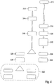
- FIG. 1 shows the basic structure of a hydraulic system for cooling an IT environment.
- n + 1 redundancy is generally realized.
- two refrigerating machines 20 are provided which contain, for example, compressors and a non-redundantly designed free cooler 30, which is followed by an EC fan 32.
- a running in V-shape heat exchanger 31 of the free cooler 30 offers based on the available space a maximum heat exchanger surface.
- Two speed-controllable pumps 40 which in turn work in n + 1 redundancy, promote the cooling medium through the chillers 20 and the free cooler 30. It is envisaged to bypass the chillers 20 hydraulically when the required cooling capacity can be generated by the free cooler 30. In the hydraulic bypass, a bypass line is released, wherein motorized valves M or a three-way valve 44 are used for fluidic control, which do not restrict the flow path.
- sensors T are available for the temperature.
- the inventive method according to claim 1 can be realized.
- the system can be part of the IT environment, as in connection with FIG. 2 explained, but also a separate module.
- data center environments that can not be connected to a customer's cooling system can be self-sufficient by using a ready-to-operate Cooling station to be supplied with cold for cooling the hardware.
- An exemplary refrigeration station is schematically shown in FIGS FIGS. 3a to 3d shown.
- FIG. 2 shows the basic structure of an exemplary IT environment with integrated refrigeration supply including the components for air conditioning.
- the hardware of the IT environment is housed, usually in racks 12, which are placed on a raised floor 14.
- the space around the racks 12 is divided into a cold aisle 16 and a hot aisle 18.
- Cold supply air symbolized by the arrow A
- the return air symbolized by the arrow B, enters a recirculating air cooling device 100 and is cooled there, wherein the cooling takes place by means of a heat exchanger 102.
- the cooled air is conveyed by the fan 104 back into the enclosure 10.
- the value of the supply air temperature is detected by two sensors T Z , which are arranged in the cold zone, namely in the cold aisle 16 or in a supply air to the double bottom 14.
- the temperature of the return air is correspondingly by a sensor T R before entering the circulating air cooler 100 recorded.
- Further sensors T z and T R can be provided to detect a number of measurements for the temperature, which are then conditioned in accordance with certain specifications already mentioned above.
- the refrigeration station as a stand-alone module which is mounted, for example, in a steel frame construction, generally designated 200, is in the FIGS. 3a to 3d shown.
- the dimensions of an ISO container are preferably selected as dimensions, so that the cooling station can be transported with standardized vehicles.
- FIG. 3a shows a hydraulic station H with redundant pumps 40, control valves, eg 44, flow meters, etc. and a controller 46, which is housed in a control cabinet or two cabinets (not shown).
- the controller 46 of the cooling station should be constructed so that this control-side link in the context of Commissioning must only be activated if a complete package of IT environment and cold station is used.
- the cooling station can thus be matched to the respective size of the data center with the appropriate design of chillers and free coolers.
- FIG. 3b shows a side view of a refrigeration station, in which schematically the already described hydraulic station H, a free cooler assembly 30 and chillers 20 are illustrated.
- the cooling station comprises two or more chillers 20, thus realizing an n + 1 redundancy.
- the refrigerating machines 20 are constructed, for example, as air-cooled refrigerating machines and have a geometry which is adapted to the preferably more compact spatial situation in order to produce the smallest possible footprint. This can be achieved, for example, by realizing the installation space for the refrigeration components in the height, for example in the form of a pillar.
- the chillers 20 are equipped with electronic expansion valves to optimize energy efficiency and may also include variable speed compressors for this purpose.
- the refrigeration station includes, as in Figure 3c shown, a free cooler 30, which, based on the available space, a designed in V-shape maximum surface of the heat exchanger 31. It is equipped with EC fans (eg 32 in Fig. 1 ) provided in order to adjust the free cooling capacity steadily even in seasonal transitional periods of the required cooling capacity.
- EC fans eg 32 in Fig. 1
- the piping system is made of polypropylene and is therefore absolutely corrosion resistant. Due to the wall thickness and the insulating effect of the plastic material used can be dispensed with the use of thermal insulation usually. Experiments have shown that the piping system can be operated with a minimum temperature of 10 ° C without condensation on the piping surfaces.
- FIG. 4 shows a schematic representation of the parameter guide in the first aspect according to the present invention.
- the increase in the setpoint value of the supply air temperature is stopped 320.
- this state represents the current maximum possible supply air temperature.
- a configurable offset can additionally ensure that the switching threshold of the hardware is always undershot.
- a reduction 330 of the setpoint value of the supply air temperature is subsequently made to the value before the start of the entire optimization process which has been stored. If the electrical power consumption of the hardware rises outside of the optimization time window, ie if no change in the supply air temperature is active, this indicates that there may be an additional Hardware assembly has been made or there is a temporary higher utilization of the hardware. A detection of the increase in the electrical power consumption of the hardware outside of the optimization time window 332 leads to no change in the setpoint value of the supply air temperature.
- the described control loop according to the present invention becomes active in the context of a time program recurring in a released period.
- the start times and the period are freely configurable.
- parameterization 402 takes place with setpoint values, in particular with the basic setpoint value for the supply air temperature.
- the measured values for the electrical power consumption of the hardware are read in at predetermined intervals 404.
- the optimization process is then started 406 in accordance with the selected parameterization of the time function. As already described, the increase 408 of the setpoint value of the supply air temperature occurs until an increase in the electrical power consumption of the supply air temperature Hardware is detected.
- the optimization process 406 then causes the feed temperature set point to be lowered 412. If the power consumption drops, then the optimization process 406 is terminated after the time function and the time function is reset. After expiration of a parameterized waiting time, the optimization process 406 is restarted.
- the optimization process 406 is terminated after time function c and the time function is subsequently reset. On the other hand, if the electrical power consumption still does not drop 420, the optimization process 406 is terminated and a request 422 is made to the user as to whether the hardware assembly has changed since the last polling time. If the hardware configuration has been changed 424, the time function of the optimization process 406 is reset so that it can be re-optimized according to the parameterized start times. However, if the hardware setup has not been changed 426, the timer function is latched 428 and a fault message is issued 430.
- FIG. 6a schematically illustrates how the setpoint of the supply air temperature determined in the optimization process flows into the further control.
- the process described above in accordance with FIG. 5 is summarized by the control loop RK7.
- the task of the control circuit RK7 is to shift the setpoint of the supply air temperature preferably to a higher value.
- the setpoint value of the supply air temperature namely, the desired value of the flow temperature for the heat exchanger is also raised, which in turn increases the limit temperature for free cooling.
- essential to the invention as a reference variable is the measurement of the electrical power consumption of the hardware.
- the optimized setpoint for the supply air temperature is used in other control processes.
- the setpoint of the supply air temperature is further increased until the electrical power consumption of the hardware increases.
- the supply air temperature set point is lowered until the electrical power consumption of the hardware returns to its original value.
- the supply air temperature is initially preferably set by the operation of fans that are assigned to the racks to be cooled.
- mean values of the supply air temperature T z and the return air temperature T R are determined.
- FIG. 6a shows, a temperature difference is calculated from the average values of the supply air temperature and the return air temperature and compared with a setpoint for the temperature difference.
- the control circuit RK6 then adjusts the fan speed of the fans. All fans are controlled in parallel with a signal. About the differential temperature control, the Setpoint of the supply air temperature to be maintained even with fluctuations in the power consumption of the hardware.
- the optimized, currently maximum possible setpoint value of the supply air temperature is used as a reference variable for the control of other components of the refrigeration supply system. This is related to FIG. 6b explained.
- FIG. 6b shows how the current maximum setpoint value of the supply air temperature is used as setpoint for the control of the control loop RK4.
- the control circuit RK4 for the flow temperature control of the heat exchanger of the circulating air cooling system is designed for example as a PID controller.
- the setpoint variable of the flow temperature for the heat exchangers is made available to the control circuits RK1 and RK2. The higher the actual maximum setpoint value of the supply air temperature, the higher the setpoint value for the flow temperature of the heat exchangers will be.
- the fans of the free cooler 30 ( FIG. 1 ) are directed with increasing outside temperature up to 100% speed.
- the temperature difference in the cooling medium returns to zero, which means that the flow is the same warm as the return, and a fan speed of 100%, the free cooler 30 is dropped.
- the discarding serves to a warm-up exclude the returning from the circulating air cooling medium in summer operation.
- the respective discharge temperature which corresponds to the outside air temperature when the discharge is triggered, is stored and used to restart the free cooler 30.
- the free cooler 30 is put into operation again when the discharge temperature by an amount .DELTA.T, which is freely parameterizable, is exceeded.
- manual intervention is possible by resetting the dump temperature via a user interface or manually parameterizing it using a numeric input field.
- the fans of the free cooler 30 are controlled at falling outside temperature to a minimum speed. Below the minimum speed of the free cooler 30 is locked in order to avoid hypothermia of the medium.
- the minimum speed can be freely parameterised as a percentage of 100.
- the free cooler 30 is put into operation again when the three-way control valve 40 is opened above a threshold value in the passage from the free cooler 30 and the flow temperature exceeds a threshold value of the temperature difference above the setpoint temperature.
- This threshold value is also freely configurable.
- the starting speed of the fans of the free cooler 30 corresponds to the speed at the lock.
- the control loop RK2 is also designed as a PID controller.
- the reference variable is the flow temperature, which is determined by the control circuit RK6.
- the three-way valve 44 is controlled with decreasing outside temperature to 100% bypass. As heat is generated permanently in the data center, 100% bypass opening will not be possible in practice. With increasing outside temperature, the three-way valve 44 is regulated to 100% passage.
- the free cooler 30 When a threshold value of the valve opening in the passage is reached by the free cooler 30, the free cooler 30 is released. After release of the free cooler, the three-way valve 44 in 100% position in the passage from the free cooler and is locked. The unlocking takes place when the free cooler 30 has again reached its parameterized measuring speed.
- the continuous speed control of the pump for the flow of the cooling medium to the heat exchangers of the circulating air cooling system is dependent on the calculated setpoint, and the flow rate measured by the flowmeter 42 continuously changes the speed of the pump.
- the setpoint of the flow rate corresponds to the nominal volume of the heat exchanger and is influenced by the control loop RK5.
- the task of the control circuit RK5 is to optimally exploit the possible delivery capacity of the pump.
- the increase in the media throughput leads to an increase in performance of the heat exchanger of the free cooler 30 and the heat exchanger of the circulating air cooling system and thus to an increase in the free cooling limit temperature.
- the drop in the fan speed of the free cooler 30 with falling outside temperature is detected and used to lower the setpoint of the flow rate again until the nominal amount of media is reached. Even with discharge of the free cooler 30, the setpoint of the flow rate is set back to the nominal amount of media.
- the control circuit RK5 is also designed as a PID controller. Reference variables are the measurement of the actual amount of water through the flow meter 42, the measured value of the electrical power consumption of the pump and the speed of the EC fan of the free cooler 30.
- the characteristic used is the Power Usage Effectiveness PUE.
- the PUE value puts the total energy consumed in the data center into relation to the energy input of the hardware. As this ratio approaches 1, it ensures that the data center operates efficiently. With the invention, PUE values of 1.3 and below can be achieved.
- FIG. 7 shows a schematic representation of the climate control according to the second aspect of the invention.
- Setpoint User-configurable temperature setpoint for air conditioning Deviation: Difference between setpoint and current temperature
- Control variable Specification for performance of the air conditioning measure disturbances: other influencing factors on the temperature (eg power loss, irradiation) Actual value: current temperature
- An evaluation unit 500 has physical input interfaces for recording sensor data for determining causal factors influencing the air conditioning requirement and can estimate the air conditioning requirement based on recorded measured values, so that a control value can be directly specified for the control of the air conditioning measures or additional factors influencing the determination of the air conditioning Manipulated variable can be provided.
- the evaluation unit thus enables a demand-based, faster and more accurate control of the air conditioning measure. The possibility of more appropriate regulation also improves the energy efficiency of the air conditioning measures.
- the evaluation unit can be realized as an independent system or integrated as a sub-function in the control of an air conditioning unit.
- the evaluation unit 500 checks at regular or irregular intervals whether measurement data are available at its input interfaces which provide information about the currently effective disturbance variables.
- controller 520 If no valid measured values are available, the output of controller 520 is used as manipulated variable. This corresponds to a classic temperature control without influence of a higher-level evaluation unit and the switch position S1 of the switch 510 in the FIG. 6 ,
- the manipulated variable used is a value obtained from the conditioning of the measured values. This corresponds to a direct control of the air conditioning measure by the evaluation unit 500 without closed loop, so switch position S3 of the switch 510th
- the output of the regulator 520 is subjected to a correction value obtained from conditioning the measured values, which is the switch position S2 of the switch 510 equivalent.
- the conditioning of the measured parameter values among other things, checking the individual measured values for their valid value range, averaging of individual measured variables, amplification of individual measured variables, addition of individual measured values to an output value, offset shift of the output value and limitation of the output value to minimum and maximum values intended.
- the evaluation unit has connection options for several sensors that can be optionally used by the user. It is thus possible for the user not to use the optimization possibilities, to use them for partial optimization of the control or to completely replace the control.
- the decision for which case the available measurements are sufficient is made on the basis of rules that can be set by experts.
- the rules specify which disturbance variables must be known by valid measurement data in order to switch to a manipulated variable influenced by the evaluation unit. Also adjustable by experts are the conditions that are used for the conditioning of the measured values.
Landscapes
- Engineering & Computer Science (AREA)
- General Engineering & Computer Science (AREA)
- Physics & Mathematics (AREA)
- Chemical & Material Sciences (AREA)
- Mechanical Engineering (AREA)
- Combustion & Propulsion (AREA)
- Thermal Sciences (AREA)
- Microelectronics & Electronic Packaging (AREA)
- Computer Hardware Design (AREA)
- General Physics & Mathematics (AREA)
- Automation & Control Theory (AREA)
- Fuzzy Systems (AREA)
- Mathematical Physics (AREA)
- Signal Processing (AREA)
- Fluid Mechanics (AREA)
- Air Conditioning Control Device (AREA)
Description
Die Erfindung geht aus von einem Verfahren zum Klimatisieren einer IT-Umgebung, die als Hardware beispielsweise IT-Geräte, Rechner, Speicher, Telekommunikationsgeräte und Peripheriegeräte umfasst, wobei in einem Kälteversorgungssystem Kältemaschinen und gegebenenfalls Freikühler und ein mit Lüftern betriebenes und Wärmetauscher enthaltendes Umluftsystem zum Abführen der von der Hardware und weiteren Komponenten des Rechenzentrums erzeugten Wärme vorhanden sind, wobei das Verfahren die Schritte aufweist: Klimatisieren der IT-Umgebung mit dem Kälteversorgungssystem, das der IT-Urngebung über das Umluftsystem Luft mit einer Zulufttemperatur zuführt; Festlegen eines Basis-Sollwertes für die Zulufttemperatur zur IT-Umgebung aufgrund der bestehenden Hardware-Konfiguration; ständiges Messen der elektrischen Leistungsaufnahme der Hardware und Speichern eines dabei jeweils gemessenen Wertes; und Ermitteln eines Sollwertes für die Zulufttemperatur aus dem gemessenen Wert für die elektrische Leistungsaufnahme der Hardware. Ein derartiges Verfahren ist aus der
Die Erfindung ist auch für Industrie-Anwendungen geeignet und auf weitere Anwendungsfälle übertragbar, beispielsweise die Raumklimatisierung.The invention is also suitable for industrial applications and transferable to other applications, such as the room air conditioning.
Als IT-Umgebung sollen Systeme jedweder Größe verstanden werden, die zumindest teilweise die oben genannte Hardware enthalten. Eine IT-Umgebung kann beispielsweise als Schaltschrank realisiert sein, als Anordnung von Schaltschränken oder als größere Einheit, bis hin zu einem Rechenzentrum.The IT environment is to be understood to mean systems of any size that at least partially contain the hardware mentioned above. For example, an IT environment can be considered Cabinet be realized, as an arrangement of cabinets or as a larger unit, to a data center.
Klimatisierungsverfahren bzw. Klimageräte werden in der Regel dazu verwendet, die Temperatur der Umgebungsluft oder eines anderen Kühlmediums auf einem jeweils bestimmten Sollwert zu halten. Dies ist erforderlich, wenn ohne Klimatisierungsmaßnahmen zulässige Grenzwerte der Temperatur über- oder unterschritten würden.Air conditioning systems or air conditioning units are usually used to keep the temperature of the ambient air or another cooling medium at a particular setpoint. This is necessary if, without air-conditioning measures, permissible temperature limits would be exceeded or fallen below.
Ein großer Teil des Stromverbrauchs in einer IT-Umgebung entfällt somit auf die Kühlung, so dass hier ein optimal angepasstes System zur Kostensenkung beitragen kann. Tatsächlich werden 25 % bis 60 % des Energiebedarfs für die Klimatisierung aufgewandt, wobei die niedrigen Werte nur mit freier Kühlung erreichbar sind. Dabei ist der größte Energieverbraucher der Kompressor im Klimagerät, der daher nur dann eingesetzt werden sollte, wenn die Außentemperatur höher ist als die Temperatur in der IT-Umgebung.A large part of the power consumption in an IT environment is thus eliminated by cooling, so that an optimally adapted system for reducing costs can contribute here. In fact, 25% to 60% of the energy requirement is spent on air conditioning, with the low values being achievable only with free cooling. The largest energy consumer is the compressor in the air conditioner, which should therefore only be used when the outside temperature is higher than the temperature in the IT environment.
Die American Society of Heating, Refrigerating and Air-Conditioning Engineers (ASHRAE) fasst in ihrem jährlich neu erscheinenden Handbuch Entwicklungen und Trends zusammen und gibt Empfehlungen für eine klimaeffiziente Gestaltung von IT-Umgebungen, die die freie Kühlung in den Vordergrund stellen. Dabei werden auch Richtlinien für als unkritisch angesehene Zulufttemperaturen für Server angegeben, die sogar kurzfristig überschritten werden dürfen. Eine Zusammenfassung ist in www.datacenterjournal.com/facilities/ashraeguidelines-enable-years-round-free-cooling/ zu finden.The American Society of Heating, Refrigerating and Air-Conditioning Engineers (ASHRAE) summarizes developments and trends in its annually published handbook and makes recommendations for the climate-efficient design of IT environments that focus on free cooling. It also specifies guidelines for non-critical supply air temperatures for servers, which may even be exceeded in the short term. A summary can be found at www.datacenterjournal.com/facilities/ashraeguidelines-enable-years-round-free-cooling/.
Weiteres zu den Richtlinien findet sich in
Herkömmliche Klimatisierungsverfahren nutzen die Zulufttemperatur für die Server als Parameter für die Regelung, wobei auf einen konstanten Sollwert für die Zulufttemperatur abgestellt wird. Als Beispiel sei das System "LCP Inline" angegeben, das im
Die
Es ist die Aufgabe der vorliegenden Erfindung, ein Verfahren zum Klimatisieren einer IT-Umgebung, einer Industrie-Umgebung oder eines Raumes zur Verfügung zu stellen, das schnell auf Änderungen der Betriebsbedingungen reagiert und bei dem, wenn vorhanden, der Anteil der Freikühlung unter Einhaltung der ASHRAE-Empfehlungen für die Zulufttemperatur zur Hardware oder eines anderen Wärmeerzeugers so hoch wie möglich ist.It is the object of the present invention to provide a method for air conditioning an IT environment, an industrial environment or a room that reacts quickly to changes in operating conditions and in which, if present, the proportion of free cooling in compliance with the ASHRAE recommendations for the supply air temperature to the hardware or other heat generator are as high as possible.
Dies kann insbesondere dann erreicht werden, wenn die Grenztemperatur für das Freikühlen so hoch wie möglich angesetzt werden kann.This can be achieved in particular if the limit temperature for free cooling can be set as high as possible.
Die Aufgabe wird durch ein Verfahren nach Anspruch 1 gelöst. Vorteilhafte Ausgestaltungen sind Gegenstand der Unteransprüche.The object is achieved by a method according to
Das erfindungsgemäße Verfahren zeichnet sich durch die folgenden Schritte aus: Anheben des Basis-Sollwertes für die Zulufttemperatur, solange keine Änderung des Wertes für die elektrische Leistungsaufnahme der Hardware ermittelt wird; bei Detektion eines Anstiegs des Wertes für die elektrische Leistungsaufnahme der Hardware auf einen kritischen Wert, Absenken des angehobenen Basis-Sollwertes für die Zulufttemperatur bis der gespeicherte Wert wieder erreicht wird; und, wenn der gespeicherte Wert innerhalb einer zuvor festgelegten Zeitdauer nicht erreicht wird, Rücksetzen des Sollwertes für die Zulufttemperatur auf den Basis-Sollwert.The inventive method is characterized by the following steps: raising the base setpoint for the supply air temperature, as long as no change in the value of the electrical power consumption of the hardware is determined; upon detecting a rise in the value of the electrical power consumption of the hardware to a critical value, lowering the raised base set point value for the supply air temperature until the stored value is reached again; and, if the stored value is not reached within a predetermined period of time, resetting the supply air temperature set point to the basic set point.
Die Erfindung nutzt jetzt die Ursache einer Temperaturveränderung zum Regeln der Klimatisierung. Ursache einer Temperaturveränderung, also Störgröße, ist dabei die Zufuhr oder Entnahme von Energie, beispielsweise in Form von elektrischer Verlustleistung, elektrische Leistungsaufnahme der Hardware, Wärmeeinstrahlung von außen, Auslastung von wärmeproduzierenden Anlagen, passive Wärmeübertragung durch Temperaturdifferenzen, Volumenstrom von Kühlmedien oder wärmetransportierenden Stoffen und dergleichen.The invention now uses the cause of a temperature change to regulate the air conditioning. The cause of a temperature change, ie disturbance, is the supply or removal of energy, for example in the form of electrical power loss, electrical power consumption of the hardware, heat radiation from the outside, utilization of heat-producing equipment, passive heat transfer by temperature differences, volume flow of cooling media or heat-transporting materials and the like.
Die Erfindung macht sich weiter die Erkenntnis zunutze, dass die Leistungsaufnahme der Hardware im Wesentlichen die Anhebung der Solltemperatur für die Zuluft festlegt und damit die Solltemperatur für den Vorlauf der Wärmetauscher mit angehoben wird, was zu einer höheren Grenztemperatur für das Freikühlen führt. Im Allgemeinen ist direkte Freikühlung möglich, wenn die Außentemperatur unterhalb von 22 °C liegt, indirekte Freikühlung erfordert Temperaturen von 13 °C oder niedriger. Die Grenztemperaturen können angehoben werden, wenn, wie erfindungsgemäß vorgesehen ist, die elektrische Leistungsaufnahme der Hardware als Führungsgröße für die Regelung eingesetzt wird. Ein kritischer Parameterwert ist dabei durch einen - gegebenenfalls toleranzbehafteten - Anstieg der elektrischen Leistungsaufnahme der Hardware definiert.The invention further makes use of the knowledge that the power consumption of the hardware substantially determines the increase in the setpoint temperature for the supply air and thus the setpoint temperature for the flow of the heat exchanger is also increased, which leads to a higher limit temperature for the free cooling. In general, direct free cooling is possible when the outside temperature is below 22 ° C, indirect free cooling requires temperatures of 13 ° C or lower. The limit temperatures can be raised if, as provided according to the invention, the electrical power consumption of the hardware is used as the reference variable for the control. A critical parameter value is defined by an increase in the electrical power consumption of the hardware, which may be subject to tolerances.
Um den ASHRAE-Empfehlungen zu genügen, wird bei der vorliegenden Erfindung ein aktuell maximal möglicher Sollwert für die Zulufttemperatur ermittelt, wobei aber hier dann, wenn ein Anstieg der elektrischen Leistungsaufnahme der Hardware gemessen wird, der Sollwert für die Zulufttemperatur wieder abgesenkt wird, bis der gespeicherte Wert der elektrischen Leistungsaufnahme der Hardware wieder erreicht ist.In order to comply with the ASHRAE recommendations, a current maximum possible setpoint for the supply air temperature is determined in the present invention, but here, if an increase in the electrical power consumption of the hardware is measured, the setpoint for the supply air temperature is lowered again until the stored value of the electrical power consumption of the hardware is reached again.
Vorteilhaft werden folgende Schritte durchgeführt:
- Messen der Zulufttemperatur zur Hardware;
- Messen der Rücklufttemperatur von der Hardware;
- Ermitteln des Sollwertes der Drehzahl für die Lüfter des Umluftsystems mit der Zulufttemperatur und der Rücklufttemperatur als Parameter;
- Messen des Istwertes der Drehzahl der Lüfter des Umluftsystems;
- Erhöhen oder Erniedrigen der Drehzahl, um Sollwert und Istwert aneinander anzugleichen, so dass ein aktualisierter Istwert erhalten wird.
- Measuring the supply air temperature to the hardware;
- Measuring the return air temperature from the hardware;
- Determining the setpoint of the speed for the fans of the recirculation system with the supply air temperature and the return air temperature as parameters;
- Measuring the actual value of the speed of the fan of the circulating air system;
- Increase or decrease the speed to match the setpoint and the actual value, so that an updated actual value is obtained.
Mit dieser Maßnahme wird sichergestellt, dass das Einhalten des Sollwertes für die Zulufttemperatur vorrangig über die energieeffizient zu betreibenden Lüfter des Umluftsystems erfolgt.This measure ensures that compliance with the setpoint for the supply air temperature takes place primarily via the fans of the circulating air system that are to be operated in an energy-efficient manner.
Weiter vorteilhaft werden alle Lüfter des Umluftsystems parallel mit einem Signal angesteuert.Further advantageously, all fans of the circulating air system are controlled in parallel with a signal.
Nach einer Variante des erfindungsgemäßen Verfahrens wird der Sollwert der Vorlauftemperatur der Wärmetauscher aus dem Istwert der Zulufttemperatur ermittelt.According to a variant of the method according to the invention, the desired value of the flow temperature of the heat exchanger is determined from the actual value of the supply air temperature.
Insbesondere kann vorgesehen sein, dass die Vorlauftemperatur der Wärmetauscher als Stellgröße für die Drehzahl der Lüfter des Freikühlers verwendet wird.In particular, it can be provided that the flow temperature of the heat exchanger is used as a control variable for the speed of the fan of the free cooler.
Nach einem weiteren Aspekt der Erfindung wird in regelmäßigen oder unregelmäßigen Abständen geprüft, ob gemessene Parameterwerte zur Verfügung stehen, die mit aktuell wirkenden Störgrößen zu korrelieren sind.According to a further aspect of the invention, it is checked at regular or irregular intervals whether measured parameter values are available which are to be correlated with currently acting disturbance variables.
Die Auswerte-Einheit prüft dazu in regelmäßigen oder unregelmäßigen Abständen, ob in ihren Eingangs-Schnittstellen Messdaten zur Verfügung stehen, die Aufschluss über die aktuell wirksamen Störgrößen geben.At regular or irregular intervals, the evaluation unit checks whether measurement data is available in its input interfaces to provide information about the currently effective disturbance variables.
Stehen keine gültigen Messwerte zur Verfügung, wird der Ausgang des Reglers als Stellgröße verwendet. Das entspricht einer klassischen Temperaturregelung ohne Einfluss einer übergeordneten Auswerte-Einheit.If no valid measured values are available, the output of the controller is used as manipulated variable. This corresponds to a classic temperature control without the influence of a higher-level evaluation unit.
Stehen ausreichend Messwerte zur Verfügung, um abzuleiten, dass bei entsprechender Einstellung der Stellgröße eine Überschreitung des vorgegebenen Sollwerts durch die aktuelle Temperatur nicht möglich ist, wird als Stellgröße ein aus Konditionierung der gemessenen Parameterwerte gewonnener Wert verwendet. Das entspricht einer direkten Steuerung der Klimatisierungsmaßnahme durch die Auswerte-Einheit ohne geschlossenen Regelkreis.If sufficient measured values are available to deduce that, if the manipulated variable is appropriately set, the preset temperature is not exceeded by the current temperature, a value obtained from conditioning the measured parameter values is used as manipulated variable. This corresponds to a direct control of the air conditioning measure by the evaluation unit without closed loop.
Stehen Messwerte zur Verfügung, die jedoch nicht ausreichen, um durch direkte Vorgabe der Stellgröße eine Nicht-Überschreitung des Sollwerts zu garantieren, wird der Ausgang des Reglers mit einem aus Konditionierung der Messwerte gewonnenen Korrektur-Wert beaufschlagt.If measured values are available, but these are not sufficient to guarantee that the setpoint is not exceeded by directly specifying the control value, the output of the Regulator applied with a correction value obtained from conditioning the measured values.
Im Folgenden soll die Erfindung lediglich beispielhaft anhand der beigefügten Zeichnung erläutert werden. Dabei zeigt:
Figur 1- den grundlegenden Aufbau eines hydraulischen Systems zur Kälteversorgung einer IT-Umgebung;
Figur 2- den grundlegenden Aufbau einer beispielhaften IT-Umgebung;
- Figur 3a
- eine schematische Ansicht der Hydraulikstation einer Kältestation;
- Figur 3b
- eine Seitenansicht einer Kältestation;
- Figur 3c
- eine Ansicht der Kältestation zur Veranschaulichung der Anordnung der Freikühler;
- Figur 3d
- schematisch die eingehausten Kältemaschinen;
- Figur 4
- eine schematische Darstellung der Parameterführung bei der vorliegenden Erfindung;
- Figur 5
- die entsprechende Prozessführung bei der optimierten Regelung;
- Figur 6a
- eine Darstellung der Regelkreise für die Ermittlung der Lüfterdrehzahl der Lüfter im Umluftkühlsystem sowie des Sollwertes der Zulufttemperatur,
- Figur 6b
- eine Darstellung der Regelkreise, mit denen sichergestellt werden soll, dass eine optimale Klimaregelung erfolgt, und
- Figur 7
- eine schematische Darstellung der Kälteversorgung nach einem weiteren Aspekt, der nicht Gegenstand der Erfindung ist.
- FIG. 1
- the basic structure of a hydraulic system for cooling an IT environment;
- FIG. 2
- the basic structure of an exemplary IT environment;
- FIG. 3a
- a schematic view of the hydraulic station of a refrigeration station;
- FIG. 3b
- a side view of a refrigeration station;
- Figure 3c
- a view of the refrigeration station to illustrate the arrangement of the free cooler;
- 3d figure
- schematically the housed refrigerators;
- FIG. 4
- a schematic representation of the parameter guide in the present invention;
- FIG. 5
- the appropriate process control in the optimized control;
- FIG. 6a
- a representation of the control circuits for determining the fan speed of the fan in the circulating air cooling system and the setpoint of the supply air temperature,
- FIG. 6b
- a representation of the control circuits to ensure that optimal climate control is provided, and
- FIG. 7
- a schematic representation of the refrigeration supply according to another aspect, which is not the subject of the invention.
Mit einem solchen System kann das erfindungsgemäße Verfahren nach Anspruch 1 realisiert werden. Das System kann dabei einerseits Bestandteil der IT-Umgebung sein, wie im Zusammenhang mit
Die Kältestation als eigenständiges Modul, das beispielsweise in einer Stahlrahmenkonstruktion montiert ist, im Allgemeinen mit 200 bezeichnet, ist in den
Die Kältestation umfasst zwei oder mehr Kältemaschinen 20, es wird damit eine n + 1-Redundanz realisiert. Die Kältemaschinen 20 sind beispielsweise als luftgekühlte Kältemaschinen aufgebaut und haben eine an die bevorzugt kompaktere Raumsituation angepasste Geometrie, um einen möglichst kleinen Footprint zu erzeugen. Dies kann beispielsweise dadurch erreicht werden, dass der Bauraum für die Kältekomponenten in die Höhe, zum Beispiel als Säulenform, realisiert wird. Die Kältemaschinen 20 werden zur Optimierung der Energie-Effizienz mit elektronischen Expansionsventilen ausgestattet und können zu diesem Zweck ebenfalls drehzahlgeregelte Kompressoren enthalten.The cooling station comprises two or
Um eine energieoptimierte Freikühlung zu erreichen, beinhaltet die Kältestation, wie in
Als weitere Kälteerzeuger sind Kältemaschinen 20 vorgesehen, die wiederum lediglich schematisch in
Das Leitungssystem besteht aus Polypropylen und ist damit absolut korrosionsbeständig. Bedingt durch die Wandstärke und die isolierende Wirkung des verwendeten Kunststoffmaterials kann in der Regel auf den Einsatz einer thermischen Isolierung verzichtet werden. Versuche haben gezeigt, dass das Leitungssystem mit einer Medientemperatur von minimal 10 °C betrieben werden kann, ohne dass Kondensat an den Leitungsoberflächen entsteht.The piping system is made of polypropylene and is therefore absolutely corrosion resistant. Due to the wall thickness and the insulating effect of the plastic material used can be dispensed with the use of thermal insulation usually. Experiments have shown that the piping system can be operated with a minimum temperature of 10 ° C without condensation on the piping surfaces.
Sobald eine Erhöhung der elektrischen Leistungsaufnahme festgestellt wird 318, wird die Erhöhung des Sollwertes der Zulufttemperatur gestoppt 320. Es erfolgt eine Absenkung 322 des Sollwertes der Zulufttemperatur auf den Betrag, der bei der Detektion des Anstiegs der elektrischen Leistungsaufnahme vorlag. Zunächst wird davon ausgegangen, dass dieser Zustand die aktuell maximal mögliche Zulufttemperatur darstellt. Durch einen parametrierbaren Offset kann zusätzlich sichergestellt werden, dass die Schaltschwelle der Hardware immer unterschritten wird. Wenn im Anschluss hieran die elektrische Leistungsaufnahme fällt 324, wird der Sollwert der Zulufttemperatur bis zum nächsten Optimierungsprozess beibehalten 326. Fällt die elektrische Leistungsaufnahme hingegen nicht 328, kann dies in einer stärkeren Belastung der Hardware, beispielsweise durch Auslastung der CPUs begründet sein. Um sicherzustellen, dass die höhere Leistungsaufnahme nicht von einer immer noch zu hohen Zulufttemperatur hervor gerufen wird, wird im Anschluss eine Absenkung 330 des Sollwertes der Zulufttemperatur auf den Wert vor Beginn des gesamten Optimierungsprozesses, der ja gespeichert worden ist, vorgenommen. Steigt die elektrische Leistungsaufnahme der Hardware außerhalb des Optimierungszeitfensters, wenn also keine Änderung der Zulufttemperatur aktiv ist, so gibt dies an, dass eventuell eine zusätzliche Hardwarebestückung vorgenommen worden ist oder eine temporär stärkere Auslastung der Hardware vorliegt. Eine Detektion des Ansteigens der elektrischen Leistungsaufnahme der Hardware außerhalb des Optimierungszeitfensters 332 führt zu keiner Veränderung des Sollwertes der Zulufttemperatur.As soon as an increase in the electric power consumption is detected 318, the increase in the setpoint value of the supply air temperature is stopped 320. There is a lowering 322 of the setpoint of the supply air temperature to the amount that existed in the detection of the increase in electrical power consumption. First, it is assumed that this state represents the current maximum possible supply air temperature. A configurable offset can additionally ensure that the switching threshold of the hardware is always undershot. When the electrical power consumption drops 324 thereafter, the supply air temperature set point is maintained until the
Der beschriebene Regelkreis gemäß der vorliegenden Erfindung wird im Rahmen eines Zeitprogramms wiederkehrend in einem freigegebenen Zeitraum aktiv. Die Startzeiten und der Zeitraum sind frei parametrierbar.The described control loop according to the present invention becomes active in the context of a time program recurring in a released period. The start times and the period are freely configurable.
In
Die Aufgabe des Regelkreises RK7 ist es, den Sollwert der Zulufttemperatur vorzugsweise auf einen höheren Wert zu verschieben. Durch eine Anhebung des Sollwertes der Zulufttemperatur wird nämlich der Sollwert der Vorlauftemperatur für die Wärmetauscher ebenfalls angehoben, was wiederum die Grenztemperatur für das Freikühlen erhöht. Dabei geht erfindungswesentlich als Führungsgröße die Messung der elektrischen Leistungsaufnahme der Hardware ein. Der optimierte Sollwert für die Zulufttemperatur wird in weiteren Regelprozessen verwendet.The task of the control circuit RK7 is to shift the setpoint of the supply air temperature preferably to a higher value. By raising the setpoint value of the supply air temperature, namely, the desired value of the flow temperature for the heat exchanger is also raised, which in turn increases the limit temperature for free cooling. In this case, essential to the invention as a reference variable is the measurement of the electrical power consumption of the hardware. The optimized setpoint for the supply air temperature is used in other control processes.
Erfindungsgemäß wird der Sollwert der Zulufttemperatur so lange weiter angehoben, bis die elektrische Leistungsaufnahme der Hardware steigt. Wenn ein Anstieg detektiert wird, erfolgt eine Absenkung des Sollwertes der Zulufttemperatur, bis die elektrische Leistungsaufnahme der Hardware wieder ihren ursprünglich festgestellten Wert eingenommen hat. Dieser Zustand definiert gemäß der vorliegenden Erfindung die aktuell maximal mögliche Zulufttemperatur.According to the setpoint of the supply air temperature is further increased until the electrical power consumption of the hardware increases. When an increase is detected, the supply air temperature set point is lowered until the electrical power consumption of the hardware returns to its original value. This state defines according to the present invention, the currently maximum possible supply air temperature.
Steigt die elektrische Leistungsaufnahme aus diesem Beharrungszustand an, so ist dies ein Hinweis auf eine zusätzliche Bestückung mit Hardware oder eine temporär stärkere Auslastung der Hardware. Eine Detektion des Ansteigens der elektrischen Leistungsaufnahme der Hardware aus dem Beharrungszustand führt zu einem Rücksetzen des Sollwertes der Zulufttemperatur auf den parametrierten und gespeicherten Betrag.Increasing the electrical power consumption from this steady state, this is an indication of additional hardware or a temporary higher utilization of the hardware. A detection of the increase in the electrical power consumption of the hardware from the steady state results in a reset of the setpoint of the supply air temperature to the parameterized and stored amount.
Im Zuge der Optimierung, was die Energieeffizienz der Klimatisierung betrifft, wird die Zulufttemperatur zunächst bevorzugt über den Betrieb von Lüftern eingestellt, die den zu kühlenden Racks zugeordnet sind. Dazu werden, wie schon erläutert, Mittelwerte der Zulufttemperatur Tz und der Rücklufttemperatur TR bestimmt. Wie aus
Eine nur temporär stärkere Auslastung der Hardware wird nach Abklingen der Lastspitze wieder zu einer Absenkung der Drehzahl der Lüfter führen.Only a temporary stronger utilization of the hardware will lead to a reduction in the speed of the fan again after the peak load has decayed.
Es wird bei der Erfindung davon abgesehen, die Zulufttemperatur in Abhängigkeit von der Drehzahl der Lüfter anzuheben oder zu senken, da dies wiederum die Differenztemperaturregelung beeinflussen würde. Eine mögliche Anhebung der Zulufttemperatur wird ausschließlich von der elektrischen Leistungsaufnahme der Hardware abhängig gemacht.It is in the invention refrained from raising or lowering the supply air temperature in dependence on the speed of the fan, as this in turn would affect the differential temperature control. A possible increase in the supply air temperature is exclusively dependent on the electrical power consumption of the hardware.
Kann die Last z. B. durch eine zusätzliche Bestückung mit Hardware bei dem parametrierten Sollwert für die Zulufttemperatur nicht mehr allein durch eine Erhöhung der Drehzahl der Lüfter abgeführt werden, so wird dies, wie im weiteren erläutert wird, automatisch abgefangen.Can the load z. B. by an additional equipment with hardware in the parameterized setpoint for the supply air temperature is no longer dissipated solely by increasing the speed of the fan, it will, as will be explained below, automatically intercepted.
Der optimierte, aktuell maximal mögliche Sollwert der Zulufttemperatur wird als Führungsgröße für die Regelung weiterer Komponenten des Kälteversorgungssystems benutzt. Dies wird im Zusammenhang mit
Die Lüfter des Freikühlers 30 (
Die jeweilige Abwurftemperatur, die der Außenlufttemperatur beim Auslösen des Abwurfs entspricht, wird gespeichert und zur Wiederinbetriebnahme des Freikühlers 30 verwendet. Der Freikühler 30 wird wieder in Betrieb genommen, wenn die Abwurftemperatur um einen Betrag ΔT, der frei parametrierbar ist, unterschritten wird. Neben dieser automatischen Inbetriebnahme ist eine manuelle Beeinflussung möglich, indem die Abwurftemperatur über eine Bedienoberfläche rückgesetzt wird oder auch über ein numerisches Eingabefeld manuell parametriert wird.The respective discharge temperature, which corresponds to the outside air temperature when the discharge is triggered, is stored and used to restart the
Die Lüfter des Freikühlers 30 werden bei sinkender Außentemperatur auf eine Mindestdrehzahl geregelt. Unterhalb der Mindestdrehzahl wird der Freikühler 30 verriegelt, um eine Unterkühlung des Mediums zu vermeiden. Die Mindestdrehzahl ist als Prozentsatz von 100 frei parametrierbar.The fans of the
Der Freikühler 30 wird wieder in Betrieb genommen, wenn das Dreiwege-Regelventil 40 über einen Schwellwert im Durchgang vom Freikühler 30 geöffnet ist und die Vorlauftemperatur einen Schwellwert der Temperaturdifferenz über der Solltemperatur überschreitet. Dieser Schwellwert ist ebenfalls frei parametrierbar.The
Die Startdrehzahl der Lüfter des Freikühlers 30 entspricht der Drehzahl bei der Verriegelung.The starting speed of the fans of the
Der Regelkreis RK2 ist ebenfalls als PID-Regler ausgeführt. Führungsgröße ist die Vorlauftemperatur, die durch den Regelkreis RK6 bestimmt wird.The control loop RK2 is also designed as a PID controller. The reference variable is the flow temperature, which is determined by the control circuit RK6.
Das Dreiwege-Ventil 44 wird bei sinkender Außentemperatur auf 100 % Bypass geregelt. Da im Rechenzentrum permanent Wärme anfällt, wird eine Bypass-Öffnung zu 100 % in der Praxis nicht erreicht werden. Bei steigender Außentemperatur wird das Dreiwege-Ventil 44 auf 100 % Durchgang geregelt.The three-
Wenn ein Schwellwert der Ventilöffnung im Durchgang vom Freikühler 30 erreicht wird, wird der Freikühler 30 freigegeben. Nach Freigabe des Freikühlers wird das Dreiwege-Ventil 44 in 100 %-Stellung im Durchgang vom Freikühler und wird verriegelt. Die Entriegelung erfolgt, wenn der Freikühler 30 wieder seine parametrierte Messdrehzahl erreicht hat.When a threshold value of the valve opening in the passage is reached by the
Im Regelkreis RK3 erfolgt die Stetigregelung der Drehzahl der Pumpe für den Durchfluss des Kühlmediums zu den Wärmetauschern des Umluftkühlsystems abhängig vom berechneten Sollwert und von der vom Durchflussmesser 42 gemessenen Durchflussmenge wird die Drehzahl der Pumpe stetig verändert. Der Sollwert der Fördermenge entspricht der Nennmedienmenge der Wärmetauscher und wird durch den Regelkreis RK5 beeinflusst.In the control circuit RK3, the continuous speed control of the pump for the flow of the cooling medium to the heat exchangers of the circulating air cooling system is dependent on the calculated setpoint, and the flow rate measured by the
Die Aufgabe des Regelkreises RK5 ist es, die mögliche Förderleistung der Pumpe optimal auszunutzen. Die Erhöhung des Mediendurchsatzes führt zu einer Leistungssteigerung des Wärmetauschers des Freikühlers 30 und der Wärmetauscher des Umluftkühlsystems und damit zu einer Erhöhung der Freikühl-Grenztemperatur.The task of the control circuit RK5 is to optimally exploit the possible delivery capacity of the pump. The increase in the media throughput leads to an increase in performance of the heat exchanger of the
Bei Anstieg der Drehzahl der Pumpe im Freikühler 30 über einen parametrierbaren Schwellwert, z. B. 95 %, hinaus wird die Drehzahl der Förderpumpe stetig angehoben, bis ein Schwellwert der elektrischen Leistungsaufnahme der Pumpe erreicht ist. Die Leistungsaufnahme steigt ab einem bestimmten Wert entsprechend einer Exponentialfunktion steil an. Der Schwellwert wird deshalb iterativ aus der Kurve der Leistungsaufnahme ermittelt und manuell parametriert.When the speed of the pump increases in the
Das Abfallen der Lüfterdrehzahl des Freikühlers 30 bei sinkender Außentemperatur wird erfasst und dazu genutzt, den Sollwert der Fördermenge wieder abzusenken, bis die Nennmedienmenge erreicht ist. Auch bei Abwurf des Freikühlers 30 wird der Sollwert der Fördermenge wieder auf die Nennmedienmenge gesetzt.The drop in the fan speed of the
Auch der Regelkreis RK5 ist als PID-Regler ausgeführt. Führungsgrößen sind die Messung der Ist-Wassermenge durch den Durchflussmesser 42, der Messwert der elektrischen Leistungsaufnahme der Pumpe sowie die Drehzahl des EC-Lüfters des Freikühlers 30.The control circuit RK5 is also designed as a PID controller. Reference variables are the measurement of the actual amount of water through the
Zur Bewertung der Effizienz der in Rechenzentren eingesetzten Energie wird als Kennwert die Power Usage Effectiveness PUE verwendet. Der PUE-Wert setzt die insgesamt im Rechenzentrum verbrauchte Energie ins Verhältnis zu der Energieaufnahme der Hardware. Wenn sich dieses Verhältnis der Zahl 1 nähert, ist sichergestellt, dass das Rechenzentrum effizient arbeitet. Mit der Erfindung können PUE-Werte von 1,3 und darunter erreicht werden.To assess the efficiency of the energy used in data centers, the characteristic used is the Power Usage Effectiveness PUE. The PUE value puts the total energy consumed in the data center into relation to the energy input of the hardware. As this ratio approaches 1, it ensures that the data center operates efficiently. With the invention, PUE values of 1.3 and below can be achieved.
Eine Auswerte-Einheit 500 verfügt über physikalische Eingangs-Schnittstellen zur Aufnahme von Sensordaten zur Bestimmung ursächlicher Einflussgrößen auf den Klimatisierungsbedarf und kann anhand von aufgenommenen Messwerten den Klimatisierungsbedarf abschätzen, so dass der Regelung der Klimatisierungsmaßnahmen eine Stellgröße direkt vorgegeben werden kann oder ergänzende Einflussgrößen zur Ermittlung der Stellgröße zur Verfügung gestellt werden können. Die Auswerte-Einheit ermöglicht so eine bedarfsgerechtere, schnellere und genauere Regelung der Klimatisierungsmaßnahme. Durch die Möglichkeit der bedarfsgerechteren Regelung kann ebenso die Energieeffizienz der Klimatisierungsmaßnahmen verbessert werden. Die Auswerte-Einheit kann als eigenständiges System realisiert werden oder als Teilfunktion in die Steuerung eines Klimatisierungsgeräts integriert werden.An
Die Auswerte-Einheit 500 prüft in regelmäßigen oder unregelmäßigen Abständen, ob an ihren Eingangs-Schnittstellen Messdaten zur Verfügung stehen, die Aufschluss über die aktuell wirksamen Störgrößen geben.The
Stehen keine gültigen Messwerte zur Verfügung, wird der Ausgang des Reglers 520 als Stellgröße verwendet. Das entspricht einer klassischen Temperaturregelung ohne Einfluss einer übergeordneten Auswerte-Einheit und der Schalterstellung S1 des Schalters 510 in der
Stehen ausreichend Messwerte zur Verfügung, um abzuleiten, dass bei entsprechender Einstellung der Stellgröße eine Überschreitung des vorgegebenen Sollwerts durch die aktuelle Temperatur nicht möglich ist, wird als Stellgröße ein aus Konditionierung der Messwerte gewonnener Wert verwendet. Das entspricht einer direkten Steuerung der Klimatisierungsmaßnahme durch die Auswerte-Einheit 500 ohne geschlossenen Regelkreis, also Schalterstellung S3 des Schalters 510.If sufficient measured values are available to deduce that, if the manipulated variable is adjusted accordingly, the preset temperature can not be exceeded by the current temperature, the manipulated variable used is a value obtained from the conditioning of the measured values. This corresponds to a direct control of the air conditioning measure by the
Stehen Messwerte zur Verfügung, die jedoch nicht ausreichen, um durch direkte Vorgabe der Stellgröße eine Nicht-Überschreitung des Sollwerts zu garantieren, wird der Ausgang des Reglers 520 mit einem aus Konditionierung der Messwerte gewonnene Korrektur-Wert beaufschlagt, was der Schalterstellung S2 des Schalters 510 entspricht.If measured values are available which, however, are insufficient to guarantee a non-exceeding of the nominal value by directly specifying the manipulated variable, the output of the
Zur Konditionierung der gemessenen Parameterwerte sind unter anderem Überprüfung der einzelnen Messgrößen auf ihren jeweils gültigen Wertebereich, Mittelwertbildung von einzelnen Messgrößen, Verstärkung von einzelnen Messgrößen, Addition von einzelnen Messwerten zu einem Ausgangswert, Offsetverschiebung des Ausgangswerts und Begrenzung des Ausgangswerts auf Minium- und Maximum-Werte vorgesehen.For the conditioning of the measured parameter values, among other things, checking the individual measured values for their valid value range, averaging of individual measured variables, amplification of individual measured variables, addition of individual measured values to an output value, offset shift of the output value and limitation of the output value to minimum and maximum values intended.
Die Auswerte-Einheit weist Anschlussmöglichkeiten für mehrere Sensoren auf, die vom Anwender optional eingesetzt werden können. So ist es für den Anwender möglich, die Optimierungsmöglichkeiten nicht zu nutzen, sie zur teilweisen Optimierung der Regelung zu nutzen oder die Regelung vollständig zu ersetzen.The evaluation unit has connection options for several sensors that can be optionally used by the user. It is thus possible for the user not to use the optimization possibilities, to use them for partial optimization of the control or to completely replace the control.
Die Entscheidung, für welchen Fall die verfügbaren Messwerte ausreichen, wird anhand von Regeln getroffen, die durch Experten eingestellt werden können. In den Regeln ist hinterlegt, welche Störgrößen durch gültige Messdaten bekannt sein müssen, um auf eine durch die Auswerte-Einheit beeinflusste Stellgröße umzuschalten. Ebenfalls durch Experten einstellbar sind die Bedingungen, die für die Konditionierung der Messwerte genutzt werden.The decision for which case the available measurements are sufficient is made on the basis of rules that can be set by experts. The rules specify which disturbance variables must be known by valid measurement data in order to switch to a manipulated variable influenced by the evaluation unit. Also adjustable by experts are the conditions that are used for the conditioning of the measured values.
Die in der vorstehenden Beschreibung, in der Zeichnung sowie in den Ansprüchen offenbarten Merkmale der Erfindung können sowohl einzeln als auch in beliebiger Kombination für die Verwirklichung der Erfindung wesentlich sein.The features of the invention disclosed in the foregoing description, in the drawing and in the claims may be essential for the realization of the invention both individually and in any desired combination.
Claims (7)
- A method for air conditioning an IT environment including, as heat generating hardware, IT devices, computers, memories, telecommunication devices and peripheral devices, wherein, in a refrigeration supply system, free coolers, refrigerators and an air circulation system operated with fans and containing heat exchangers for drawing off the heat generated by the hardware are provided; comprising:- air conditioning an IT environment with the refrigeration supply system which supplies air with a feed air temperature to the IT environment via the air circulation system;- determining a basic desired value for the feed air temperature to the IT environment on the basis of the existing hardware configuration;- continuously measuring the electrical power consumption of the hardware and memories and storing a respective value measured in the process;- determining a desired value for the feed air temperature from the measured value for the electrical power consumption of the hardware,characterized in that- raising the desired value for the feed air temperature as long as no change of the value of the electrical power consumption of the hardware has been detected, then,- in the case of detection of an increase of the value for the electrical power consumption of the hardware towards a critical value, lowering of the raised basic desired value for the feed air temperature until the stored value is reached again; and- if the stored value is not reached within a previously defined time period, resetting of the desired value for the feed air temperature to the basic desired value.
- The method according to claim 1, further comprising:- measuring the feed air temperature toward the hardware;- measuring the return air temperature from the hardware;- determining the desired value of the rotation speed for the fans of the air circulation system with the feed air temperature and the return air temperature as parameters;- measuring the actual value of the rotation speed of the fans of the air circulation system;- increasing or lowering the rotation speed in order to match the desired value and the actual value to one another, so that an updated actual value is obtained.
- The method according to claim 1, wherein all the fans of the air circulation system are controlled in parallel with one signal.
- The method according to claim 1, further comprising:- determining the desired value of the feed flow temperature of the heat exchangers from the actual value of the feed air temperature.
- The method according to claim 4, wherein the feed flow temperature of the heat exchangers is used as setting variable for the rotation speed of the fans of the free cooler.
- The method according to claim 1, wherein a verification is carried out at regular or irregular intervals in order to determine whether measured parameter values that correlate with currently acting disturbance variables are available.
- The method according to claim 6, wherein the measured parameter values are conditioned and the conditioned value determines the setting variable of the feedback control.
Applications Claiming Priority (3)
| Application Number | Priority Date | Filing Date | Title |
|---|---|---|---|
| DE102013100524 | 2013-01-18 | ||
| DE102013111053.3A DE102013111053A1 (en) | 2013-01-18 | 2013-10-07 | Method for conditioning an IT environment or environment that contains heat generators |
| PCT/DE2014/100008 WO2014111087A1 (en) | 2013-01-18 | 2014-01-15 | Method for adaptation of a desired value for air conditioning of an it environment |
Publications (2)
| Publication Number | Publication Date |
|---|---|
| EP2946258A1 EP2946258A1 (en) | 2015-11-25 |
| EP2946258B1 true EP2946258B1 (en) | 2017-01-04 |
Family
ID=51064357
Family Applications (1)
| Application Number | Title | Priority Date | Filing Date |
|---|---|---|---|
| EP14706280.6A Active EP2946258B1 (en) | 2013-01-18 | 2014-01-15 | Method for adaptation of a desired value for conditioning the air of an it environment |
Country Status (5)
| Country | Link |
|---|---|
| US (1) | US10047966B2 (en) |
| EP (1) | EP2946258B1 (en) |
| CN (1) | CN105144014B (en) |
| DE (1) | DE102013111053A1 (en) |
| WO (1) | WO2014111087A1 (en) |
Families Citing this family (7)
| Publication number | Priority date | Publication date | Assignee | Title |
|---|---|---|---|---|
| DE102014101404B4 (en) | 2014-02-05 | 2017-11-16 | Rittal Gmbh & Co. Kg | Frame for a switch or distribution cabinet |
| DE102015104843A1 (en) * | 2015-03-30 | 2016-10-06 | Rittal Gmbh & Co. Kg | Control method for a control cabinet cooling unit |
| EP3403151A4 (en) | 2016-01-12 | 2019-12-25 | Optimum Energy, LLC | Predictive free cooling |
| DE102016115175A1 (en) | 2016-08-16 | 2018-02-22 | Rittal Gmbh & Co. Kg | Cooling arrangement for the air conditioning of an IT environment and in particular for the data center air conditioning |
| US10881032B1 (en) | 2017-03-09 | 2020-12-29 | Equinix, Inc. | Cooling unit fan speed control |
| EP3914867A1 (en) * | 2019-01-22 | 2021-12-01 | Maersk Container Industry A/S | Surveillance of a plurality of refrigerated containers and determination of an insulation parameter of a refrigerated container |
| CN114253318B (en) * | 2021-12-06 | 2022-08-16 | 北京金林高科科技有限公司 | Temperature control method based on smart home |
Family Cites Families (35)
| Publication number | Priority date | Publication date | Assignee | Title |
|---|---|---|---|---|
| US5195473A (en) * | 1989-09-08 | 1993-03-23 | Nissan Motor Company, Ltd. | Rocker arm and method of casting |
| JP3175237B2 (en) | 1991-10-08 | 2001-06-11 | 株式会社デンソー | Vehicle air conditioner |
| US5467609A (en) | 1993-04-23 | 1995-11-21 | Liebert Corporation | Modular floor sub-structure for the operational support of computer systems |
| US5485953A (en) * | 1995-01-26 | 1996-01-23 | Gas Research Institute | Method and apparatus for controlling the circulation of heat transfer fluid for thermal conditioning systems for spaces |
| US5915473A (en) | 1997-01-29 | 1999-06-29 | American Standard Inc. | Integrated humidity and temperature controller |
| DE19942491A1 (en) | 1999-09-06 | 2001-04-05 | Duerr Systems Gmbh | Method for regulating a supply air conditioning system and control device for a supply air conditioning system |
| US6188189B1 (en) * | 1999-12-23 | 2001-02-13 | Analog Devices, Inc. | Fan speed control system |
| AU2002220199A1 (en) | 2000-11-09 | 2002-05-21 | Jay D. Ray | Raised floor air handling unit |
| US6775997B2 (en) | 2002-10-03 | 2004-08-17 | Hewlett-Packard Development Company, L.P. | Cooling of data centers |
| US7046514B2 (en) | 2003-03-19 | 2006-05-16 | American Power Conversion Corporation | Data center cooling |
| US6881142B1 (en) | 2003-09-12 | 2005-04-19 | Degree C | Intelligent networked fan assisted tiles for adaptive thermal management of thermally sensitive rooms |
| US20060168975A1 (en) | 2005-01-28 | 2006-08-03 | Hewlett-Packard Development Company, L.P. | Thermal and power management apparatus |
| JP4585325B2 (en) | 2005-02-08 | 2010-11-24 | 株式会社日立製作所 | Disk array device |
| EP2036412B1 (en) | 2006-06-01 | 2012-11-14 | Exaflop LLC | Controlled warm air capture |
| CA2653817C (en) | 2006-06-01 | 2012-10-16 | Google Inc. | Modular computing environments |
| CN101137279B (en) | 2007-10-17 | 2010-05-19 | 福州高意通讯有限公司 | Temperature control structure of photoelectric device |
| JP4780479B2 (en) * | 2008-02-13 | 2011-09-28 | 株式会社日立プラントテクノロジー | Electronic equipment cooling system |
| DE102008012215A1 (en) | 2008-03-03 | 2009-09-10 | SCHäFER WERKE GMBH | Double floor system in data centers and server rooms, especially as pressure floor with ventilation supply |
| US7791882B2 (en) * | 2008-04-23 | 2010-09-07 | International Business Machines Corporation | Energy efficient apparatus and method for cooling an electronics rack |
| US8849630B2 (en) * | 2008-06-26 | 2014-09-30 | International Business Machines Corporation | Techniques to predict three-dimensional thermal distributions in real-time |
| US8346398B2 (en) * | 2008-08-08 | 2013-01-01 | Siemens Industry, Inc. | Data center thermal performance optimization using distributed cooling systems |
| JP5218276B2 (en) * | 2009-05-19 | 2013-06-26 | 富士通株式会社 | Air conditioning control system, air conditioning control method, and air conditioning control program |
| US9101080B2 (en) | 2009-09-28 | 2015-08-04 | Amazon Technologies, Inc. | Modular computing system for a data center |
| JP5192469B2 (en) | 2009-09-30 | 2013-05-08 | 株式会社日立製作所 | Electronic equipment cooling structure |
| DE202009015124U1 (en) | 2009-11-05 | 2010-03-04 | Knürr AG | Arrangement for cooling electrical and electronic components and modular units in equipment cabinets |
| CN102105033B (en) | 2009-12-17 | 2013-06-19 | 台达电子工业股份有限公司 | System and method for adjusting environment of portable data center |
| US8373987B2 (en) | 2009-12-17 | 2013-02-12 | Delta Electronics, Inc. | Air conditioning system of portable data center |
| US20110223085A1 (en) | 2010-03-12 | 2011-09-15 | E. I. Du Pont De Nemours And Company | Carbon dioxide capture with ionic liquid electrospray |
| DE102010031830A1 (en) * | 2010-07-20 | 2012-01-26 | Hans-Georg Fleischmann | Adaptive disturbance variable sensor and adaptive control system for a weather-compensated domestic engineering control and method for operating this |
| US8090477B1 (en) * | 2010-08-20 | 2012-01-03 | Ecofactor, Inc. | System and method for optimizing use of plug-in air conditioners and portable heaters |
| TW201212798A (en) | 2010-09-02 | 2012-03-16 | Hon Hai Prec Ind Co Ltd | Computer server cabinet |
| KR20120044593A (en) | 2010-10-28 | 2012-05-08 | 엘지전자 주식회사 | Air conditioning device and control method of the same |
| US8554390B2 (en) | 2010-11-16 | 2013-10-08 | International Business Machines Corporation | Free cooling solution for a containerized data center |
| US8694166B2 (en) * | 2011-06-02 | 2014-04-08 | Verizon Patent And Licensing Inc. | Dynamic HVAC airside economizer high limit start control |
| US8718835B2 (en) * | 2011-06-17 | 2014-05-06 | Microsoft Corporation | Optimized temperature-driven device cooling |
-
2013
- 2013-10-07 DE DE102013111053.3A patent/DE102013111053A1/en not_active Withdrawn
-
2014
- 2014-01-15 EP EP14706280.6A patent/EP2946258B1/en active Active
- 2014-01-15 US US14/761,902 patent/US10047966B2/en active Active
- 2014-01-15 WO PCT/DE2014/100008 patent/WO2014111087A1/en active Application Filing
- 2014-01-15 CN CN201480016915.XA patent/CN105144014B/en active Active
Non-Patent Citations (1)
| Title |
|---|
| None * |
Also Published As
| Publication number | Publication date |
|---|---|
| US20150377509A1 (en) | 2015-12-31 |
| US10047966B2 (en) | 2018-08-14 |
| CN105144014A (en) | 2015-12-09 |
| EP2946258A1 (en) | 2015-11-25 |
| DE102013111053A1 (en) | 2014-07-24 |
| CN105144014B (en) | 2017-09-26 |
| WO2014111087A1 (en) | 2014-07-24 |
Similar Documents
| Publication | Publication Date | Title |
|---|---|---|
| EP2946258B1 (en) | Method for adaptation of a desired value for conditioning the air of an it environment | |
| EP2591646B1 (en) | System and method for cooling a computer system | |
| DE102016123330B4 (en) | Laser device with condensation prevention function | |
| DE60116433T2 (en) | Control method based on radiator throttling and output overheating of an electronic expansion valve | |
| DE102011000638B4 (en) | Method and device for controlling and monitoring an air conditioning system for data processing systems | |
| EP1960850B1 (en) | Control method for cooling an industrial plant | |
| DE60305436T2 (en) | COOLING SYSTEM WITH SERIES EVAPORIZERS TURNOVER-ORIENTED TUBE BUNDLE | |
| DE10231877B4 (en) | Konstanttemperaturflüssigkeitszirkuliervorrichtung | |
| DE102008015222B4 (en) | Remote power monitoring method | |
| DE102014109331B4 (en) | Constant temperature liquid circulating apparatus and method of operation therefor | |
| DE102013114374B4 (en) | Method for controlling the speed of a variable speed compressor | |
| DE3140273A1 (en) | "AUTHORIZED FAULT DIAGNOSIS ARRANGEMENT FOR A HEAT PUMP AIR CONDITIONING OR AIR CONDITIONING SYSTEM" | |
| EP2456293A2 (en) | Cooling assembly and method for a ventilator control | |
| WO2011082790A1 (en) | System and method for cooling a processing system | |
| DE69302591T2 (en) | Automatic shutdown sequence for a cooler | |
| DE102017204526A1 (en) | Method for cooling an inverter, in particular a frequency converter in a heat pump cycle | |
| DE10028517A1 (en) | Thermostatic coolant circulation device | |
| EP1350068B1 (en) | Method for regulating a cooling appliance | |
| AT522875A4 (en) | Method for controlling an expansion valve | |
| EP4259978A1 (en) | Method for operating a heat pump | |
| DE112020006579T5 (en) | Heat pump unit, heat pump system, air conditioning and chiller | |
| WO2009053241A2 (en) | Refrigerator | |
| EP3244143A1 (en) | Cooling device | |
| DE102021213973A1 (en) | Thermal management system control method for a vehicle | |
| DE102023106862A1 (en) | Method for monitoring loss of working fluid from a heat pump and correspondingly monitored heat pump |
Legal Events
| Date | Code | Title | Description |
|---|---|---|---|
| PUAI | Public reference made under article 153(3) epc to a published international application that has entered the european phase |
Free format text: ORIGINAL CODE: 0009012 |
|
| 17P | Request for examination filed |
Effective date: 20150706 |
|
| AK | Designated contracting states |
Kind code of ref document: A1 Designated state(s): AL AT BE BG CH CY CZ DE DK EE ES FI FR GB GR HR HU IE IS IT LI LT LU LV MC MK MT NL NO PL PT RO RS SE SI SK SM TR |
|
| AX | Request for extension of the european patent |
Extension state: BA ME |
|
| RIN1 | Information on inventor provided before grant (corrected) |
Inventor name: SIEGEL, TIM Inventor name: NONN, HELMUT Inventor name: NICOLAI, MICHAEL |
|
| DAX | Request for extension of the european patent (deleted) | ||
| REG | Reference to a national code |
Ref country code: DE Ref legal event code: R079 Ref document number: 502014002405 Country of ref document: DE Free format text: PREVIOUS MAIN CLASS: G05D0023190000 Ipc: F24F0011000000 |
|
| GRAP | Despatch of communication of intention to grant a patent |
Free format text: ORIGINAL CODE: EPIDOSNIGR1 |
|
| RIC1 | Information provided on ipc code assigned before grant |
Ipc: F24F 11/00 20060101AFI20160829BHEP Ipc: H05K 7/20 20060101ALI20160829BHEP Ipc: G05D 23/19 20060101ALI20160829BHEP |
|
| INTG | Intention to grant announced |
Effective date: 20160915 |
|
| GRAS | Grant fee paid |
Free format text: ORIGINAL CODE: EPIDOSNIGR3 |
|
| GRAA | (expected) grant |
Free format text: ORIGINAL CODE: 0009210 |
|
| AK | Designated contracting states |
Kind code of ref document: B1 Designated state(s): AL AT BE BG CH CY CZ DE DK EE ES FI FR GB GR HR HU IE IS IT LI LT LU LV MC MK MT NL NO PL PT RO RS SE SI SK SM TR |
|
| REG | Reference to a national code |
Ref country code: GB Ref legal event code: FG4D Free format text: NOT ENGLISH |
|
| REG | Reference to a national code |
Ref country code: CH Ref legal event code: EP |
|
| REG | Reference to a national code |
Ref country code: AT Ref legal event code: REF Ref document number: 859637 Country of ref document: AT Kind code of ref document: T Effective date: 20170115 |
|
| REG | Reference to a national code |
Ref country code: FR Ref legal event code: PLFP Year of fee payment: 4 |
|
| REG | Reference to a national code |
Ref country code: IE Ref legal event code: FG4D Free format text: LANGUAGE OF EP DOCUMENT: GERMAN |
|
| REG | Reference to a national code |
Ref country code: DE Ref legal event code: R096 Ref document number: 502014002405 Country of ref document: DE |
|
| REG | Reference to a national code |
Ref country code: LT Ref legal event code: MG4D Ref country code: NL Ref legal event code: MP Effective date: 20170104 |
|
| PG25 | Lapsed in a contracting state [announced via postgrant information from national office to epo] |
Ref country code: BE Free format text: LAPSE BECAUSE OF NON-PAYMENT OF DUE FEES Effective date: 20170131 |
|
| PG25 | Lapsed in a contracting state [announced via postgrant information from national office to epo] |
Ref country code: NL Free format text: LAPSE BECAUSE OF FAILURE TO SUBMIT A TRANSLATION OF THE DESCRIPTION OR TO PAY THE FEE WITHIN THE PRESCRIBED TIME-LIMIT Effective date: 20170104 |
|
| PG25 | Lapsed in a contracting state [announced via postgrant information from national office to epo] |
Ref country code: GR Free format text: LAPSE BECAUSE OF FAILURE TO SUBMIT A TRANSLATION OF THE DESCRIPTION OR TO PAY THE FEE WITHIN THE PRESCRIBED TIME-LIMIT Effective date: 20170405 Ref country code: NO Free format text: LAPSE BECAUSE OF FAILURE TO SUBMIT A TRANSLATION OF THE DESCRIPTION OR TO PAY THE FEE WITHIN THE PRESCRIBED TIME-LIMIT Effective date: 20170404 Ref country code: FI Free format text: LAPSE BECAUSE OF FAILURE TO SUBMIT A TRANSLATION OF THE DESCRIPTION OR TO PAY THE FEE WITHIN THE PRESCRIBED TIME-LIMIT Effective date: 20170104 Ref country code: LT Free format text: LAPSE BECAUSE OF FAILURE TO SUBMIT A TRANSLATION OF THE DESCRIPTION OR TO PAY THE FEE WITHIN THE PRESCRIBED TIME-LIMIT Effective date: 20170104 Ref country code: HR Free format text: LAPSE BECAUSE OF FAILURE TO SUBMIT A TRANSLATION OF THE DESCRIPTION OR TO PAY THE FEE WITHIN THE PRESCRIBED TIME-LIMIT Effective date: 20170104 Ref country code: IS Free format text: LAPSE BECAUSE OF FAILURE TO SUBMIT A TRANSLATION OF THE DESCRIPTION OR TO PAY THE FEE WITHIN THE PRESCRIBED TIME-LIMIT Effective date: 20170504 |
|
| PG25 | Lapsed in a contracting state [announced via postgrant information from national office to epo] |
Ref country code: SE Free format text: LAPSE BECAUSE OF FAILURE TO SUBMIT A TRANSLATION OF THE DESCRIPTION OR TO PAY THE FEE WITHIN THE PRESCRIBED TIME-LIMIT Effective date: 20170104 Ref country code: PT Free format text: LAPSE BECAUSE OF FAILURE TO SUBMIT A TRANSLATION OF THE DESCRIPTION OR TO PAY THE FEE WITHIN THE PRESCRIBED TIME-LIMIT Effective date: 20170504 Ref country code: LV Free format text: LAPSE BECAUSE OF FAILURE TO SUBMIT A TRANSLATION OF THE DESCRIPTION OR TO PAY THE FEE WITHIN THE PRESCRIBED TIME-LIMIT Effective date: 20170104 Ref country code: RS Free format text: LAPSE BECAUSE OF FAILURE TO SUBMIT A TRANSLATION OF THE DESCRIPTION OR TO PAY THE FEE WITHIN THE PRESCRIBED TIME-LIMIT Effective date: 20170104 Ref country code: BG Free format text: LAPSE BECAUSE OF FAILURE TO SUBMIT A TRANSLATION OF THE DESCRIPTION OR TO PAY THE FEE WITHIN THE PRESCRIBED TIME-LIMIT Effective date: 20170404 Ref country code: PL Free format text: LAPSE BECAUSE OF FAILURE TO SUBMIT A TRANSLATION OF THE DESCRIPTION OR TO PAY THE FEE WITHIN THE PRESCRIBED TIME-LIMIT Effective date: 20170104 Ref country code: ES Free format text: LAPSE BECAUSE OF FAILURE TO SUBMIT A TRANSLATION OF THE DESCRIPTION OR TO PAY THE FEE WITHIN THE PRESCRIBED TIME-LIMIT Effective date: 20170104 |
|
| REG | Reference to a national code |
Ref country code: CH Ref legal event code: PL |
|
| REG | Reference to a national code |
Ref country code: DE Ref legal event code: R097 Ref document number: 502014002405 Country of ref document: DE |
|
| PG25 | Lapsed in a contracting state [announced via postgrant information from national office to epo] |
Ref country code: SK Free format text: LAPSE BECAUSE OF FAILURE TO SUBMIT A TRANSLATION OF THE DESCRIPTION OR TO PAY THE FEE WITHIN THE PRESCRIBED TIME-LIMIT Effective date: 20170104 Ref country code: CZ Free format text: LAPSE BECAUSE OF FAILURE TO SUBMIT A TRANSLATION OF THE DESCRIPTION OR TO PAY THE FEE WITHIN THE PRESCRIBED TIME-LIMIT Effective date: 20170104 Ref country code: EE Free format text: LAPSE BECAUSE OF FAILURE TO SUBMIT A TRANSLATION OF THE DESCRIPTION OR TO PAY THE FEE WITHIN THE PRESCRIBED TIME-LIMIT Effective date: 20170104 Ref country code: RO Free format text: LAPSE BECAUSE OF FAILURE TO SUBMIT A TRANSLATION OF THE DESCRIPTION OR TO PAY THE FEE WITHIN THE PRESCRIBED TIME-LIMIT Effective date: 20170104 Ref country code: LI Free format text: LAPSE BECAUSE OF NON-PAYMENT OF DUE FEES Effective date: 20170131 Ref country code: CH Free format text: LAPSE BECAUSE OF NON-PAYMENT OF DUE FEES Effective date: 20170131 |
|
| REG | Reference to a national code |
Ref country code: IE Ref legal event code: MM4A |
|
| PLBE | No opposition filed within time limit |
Free format text: ORIGINAL CODE: 0009261 |
|
| STAA | Information on the status of an ep patent application or granted ep patent |
Free format text: STATUS: NO OPPOSITION FILED WITHIN TIME LIMIT |
|
| PG25 | Lapsed in a contracting state [announced via postgrant information from national office to epo] |
Ref country code: DK Free format text: LAPSE BECAUSE OF FAILURE TO SUBMIT A TRANSLATION OF THE DESCRIPTION OR TO PAY THE FEE WITHIN THE PRESCRIBED TIME-LIMIT Effective date: 20170104 Ref country code: LU Free format text: LAPSE BECAUSE OF NON-PAYMENT OF DUE FEES Effective date: 20170115 Ref country code: SM Free format text: LAPSE BECAUSE OF FAILURE TO SUBMIT A TRANSLATION OF THE DESCRIPTION OR TO PAY THE FEE WITHIN THE PRESCRIBED TIME-LIMIT Effective date: 20170104 Ref country code: MC Free format text: LAPSE BECAUSE OF FAILURE TO SUBMIT A TRANSLATION OF THE DESCRIPTION OR TO PAY THE FEE WITHIN THE PRESCRIBED TIME-LIMIT Effective date: 20170104 |
|
| REG | Reference to a national code |
Ref country code: FR Ref legal event code: PLFP Year of fee payment: 5 |
|
| REG | Reference to a national code |
Ref country code: BE Ref legal event code: MM Effective date: 20170131 |
|
| PG25 | Lapsed in a contracting state [announced via postgrant information from national office to epo] |
Ref country code: SI Free format text: LAPSE BECAUSE OF FAILURE TO SUBMIT A TRANSLATION OF THE DESCRIPTION OR TO PAY THE FEE WITHIN THE PRESCRIBED TIME-LIMIT Effective date: 20170104 Ref country code: IE Free format text: LAPSE BECAUSE OF NON-PAYMENT OF DUE FEES Effective date: 20170115 |
|
| PG25 | Lapsed in a contracting state [announced via postgrant information from national office to epo] |
Ref country code: MT Free format text: LAPSE BECAUSE OF FAILURE TO SUBMIT A TRANSLATION OF THE DESCRIPTION OR TO PAY THE FEE WITHIN THE PRESCRIBED TIME-LIMIT Effective date: 20170104 |
|
| PG25 | Lapsed in a contracting state [announced via postgrant information from national office to epo] |
Ref country code: HU Free format text: LAPSE BECAUSE OF FAILURE TO SUBMIT A TRANSLATION OF THE DESCRIPTION OR TO PAY THE FEE WITHIN THE PRESCRIBED TIME-LIMIT; INVALID AB INITIO Effective date: 20140115 |
|
| PG25 | Lapsed in a contracting state [announced via postgrant information from national office to epo] |
Ref country code: CY Free format text: LAPSE BECAUSE OF FAILURE TO SUBMIT A TRANSLATION OF THE DESCRIPTION OR TO PAY THE FEE WITHIN THE PRESCRIBED TIME-LIMIT Effective date: 20170104 |
|
| PG25 | Lapsed in a contracting state [announced via postgrant information from national office to epo] |
Ref country code: MK Free format text: LAPSE BECAUSE OF FAILURE TO SUBMIT A TRANSLATION OF THE DESCRIPTION OR TO PAY THE FEE WITHIN THE PRESCRIBED TIME-LIMIT Effective date: 20170104 |
|
| REG | Reference to a national code |
Ref country code: AT Ref legal event code: MM01 Ref document number: 859637 Country of ref document: AT Kind code of ref document: T Effective date: 20190115 |
|
| PG25 | Lapsed in a contracting state [announced via postgrant information from national office to epo] |
Ref country code: TR Free format text: LAPSE BECAUSE OF FAILURE TO SUBMIT A TRANSLATION OF THE DESCRIPTION OR TO PAY THE FEE WITHIN THE PRESCRIBED TIME-LIMIT Effective date: 20170104 |
|
| PG25 | Lapsed in a contracting state [announced via postgrant information from national office to epo] |
Ref country code: AT Free format text: LAPSE BECAUSE OF NON-PAYMENT OF DUE FEES Effective date: 20190115 |
|
| PG25 | Lapsed in a contracting state [announced via postgrant information from national office to epo] |
Ref country code: AL Free format text: LAPSE BECAUSE OF FAILURE TO SUBMIT A TRANSLATION OF THE DESCRIPTION OR TO PAY THE FEE WITHIN THE PRESCRIBED TIME-LIMIT Effective date: 20170104 |
|
| P01 | Opt-out of the competence of the unified patent court (upc) registered |
Effective date: 20230525 |
|
| PGFP | Annual fee paid to national office [announced via postgrant information from national office to epo] |
Ref country code: DE Payment date: 20240119 Year of fee payment: 11 Ref country code: GB Payment date: 20240124 Year of fee payment: 11 |
|
| PGFP | Annual fee paid to national office [announced via postgrant information from national office to epo] |
Ref country code: IT Payment date: 20240131 Year of fee payment: 11 Ref country code: FR Payment date: 20240124 Year of fee payment: 11 |