EP2946239B1 - Technik zum einschieben und herausnehmen einer optischen relais verstärkerstation - Google Patents
Technik zum einschieben und herausnehmen einer optischen relais verstärkerstation Download PDFInfo
- Publication number
- EP2946239B1 EP2946239B1 EP14702391.5A EP14702391A EP2946239B1 EP 2946239 B1 EP2946239 B1 EP 2946239B1 EP 14702391 A EP14702391 A EP 14702391A EP 2946239 B1 EP2946239 B1 EP 2946239B1
- Authority
- EP
- European Patent Office
- Prior art keywords
- repeater
- chassis
- guide rod
- amplifier assembly
- guide
- Prior art date
- Legal status (The legal status is an assumption and is not a legal conclusion. Google has not performed a legal analysis and makes no representation as to the accuracy of the status listed.)
- Active
Links
Images



Classifications
-
- H—ELECTRICITY
- H04—ELECTRIC COMMUNICATION TECHNIQUE
- H04B—TRANSMISSION
- H04B10/00—Transmission systems employing electromagnetic waves other than radio-waves, e.g. infrared, visible or ultraviolet light, or employing corpuscular radiation, e.g. quantum communication
- H04B10/29—Repeaters
-
- G—PHYSICS
- G02—OPTICS
- G02B—OPTICAL ELEMENTS, SYSTEMS OR APPARATUS
- G02B6/00—Light guides; Structural details of arrangements comprising light guides and other optical elements, e.g. couplings
- G02B6/44—Mechanical structures for providing tensile strength and external protection for fibres, e.g. optical transmission cables
- G02B6/4439—Auxiliary devices
- G02B6/444—Systems or boxes with surplus lengths
- G02B6/4441—Boxes
- G02B6/4448—Electro-optic
-
- H—ELECTRICITY
- H04—ELECTRIC COMMUNICATION TECHNIQUE
- H04J—MULTIPLEX COMMUNICATION
- H04J14/00—Optical multiplex systems
- H04J14/02—Wavelength-division multiplex systems
-
- Y—GENERAL TAGGING OF NEW TECHNOLOGICAL DEVELOPMENTS; GENERAL TAGGING OF CROSS-SECTIONAL TECHNOLOGIES SPANNING OVER SEVERAL SECTIONS OF THE IPC; TECHNICAL SUBJECTS COVERED BY FORMER USPC CROSS-REFERENCE ART COLLECTIONS [XRACs] AND DIGESTS
- Y10—TECHNICAL SUBJECTS COVERED BY FORMER USPC
- Y10T—TECHNICAL SUBJECTS COVERED BY FORMER US CLASSIFICATION
- Y10T29/00—Metal working
- Y10T29/49—Method of mechanical manufacture
- Y10T29/49826—Assembling or joining
Definitions
- Fiber-optic communication networks serve a key demand of the information age by providing high-speed data between network nodes.
- Fiber-optic communication networks include an aggregation of interconnected fiber-optic links.
- a fiber-optic link involves an optical signal source that emits information in the form of light into an optical fiber. Due to principles of internal reflection, the optical signal propagates through the optical fiber until it is eventually received into an optical signal receiver. If the fiber-optic link is bi-directional, information may be optically communicated in reverse typically using a separate optical fiber.
- Fiber-optic links are used in a wide variety of applications, each requiring different lengths of fiber-optic links. For instance, relatively short fiber-optic links may be used to communicate information between a computer and its proximate peripherals, or between a local video source (such as a DVD or DVR) and a television. On the opposite extreme, however, fiber-optic links may extend hundreds or even thousands of kilometers when the information is to be communicated between two network nodes.
- Long-haul and ultra-long-haul optics refers to the transmission of light signals over long fiber-optic links on the order of hundreds or thousands of kilometers.
- long-haul optics involves the transmission of optical signals on separate channels over a single optical fiber, each channel corresponding to a distinct wavelength of light using principles of Wavelength Division Multiplexing (WDM) or Dense WDM (DWDM).
- WDM Wavelength Division Multiplexing
- DWDM Dense WDM
- Repeaters that include optical amplifiers are often used in order to extend the reach of fiber-optic links.
- Such optical amplifiers may include, for instance, rare-Earth doped fibers and semiconductor-based optical pumps that power the rare-Earth doped fibers.
- the repeaters therefore have a supply of electrical power, and drop power to the optical pumps.
- the repeaters also have heat dissipation characteristics which allow the heat generated by the repeater to be dissipated to the ambient environment.
- Repeaters are often situated underwater perhaps on the ocean floor when, for instance, they are used for trans-oceanic fiber-optic links. Such repeaters are termed "submarine" optical repeaters. In submarine repeaters, the heat is to be dissipated to the surrounding ocean, which is typically just several degrees Celsius at the depths that most submarine repeaters operate at.
- Repeaters typically include a housing, an insulating layer, and the amplifier assembly itself.
- the cable includes optical fiber pairs (each pair having an eastern fiber for communication in one direction, and a western fiber for communication in the opposite direction).
- the cable also has a conductor for delivery of electrical power.
- the housing is typically composed of metal and is actually in contact with the ambient environment (sea water in the case of a submarine repeater).
- the insulating layer is typically a polymeric sleeve and acts to electrically insulate the amplifier assembly from the housing.
- the polymeric sleeve is typically in good intimate contact with the housing.
- the amplifier assembly should also have intimate contact with the polymeric sleeve. This promotes heat transfer from the amplifier assembly, through the polymeric sleeve, through the housing, and into the ambient environment.
- Amplifiers are typically inserted into housings and then forced out mechanically against the polymeric sleeve to create the intimate contact required to promote good heat transfer.
- At least one embodiment described herein relates to a repeater amplifier assembly that includes at least two chassis containing optics and electronics.
- the chassis are connected with a size-adjustment mechanism that can adjust the size of the repeater amplifier assembly by reversibly adjusting the positions of the chassis with respect to each other.
- the repeater amplifier assembly is accessed in a contracted position.
- the amplifier is inserted into the housing, and then a control of the size adjustment mechanism is actuated to urge the chassis outwards with respect to each other to cause the chassis to push against the polymeric sleeve and housing.
- the control is actuated to cause the size adjustment mechanism to pull the chassis inwards with respect to each other until the chassis no longer push against the polymeric sleeve and repeater housing.
- the repeater amplifier assembly may then be freely removed from the repeater housing.
- the control may be used to actuate multiple instances of the repeater amplifier assembly, each having a corresponding size-adjustment mechanism.
- a repeater amplifier assembly has an adjustable size that may be manipulated to allow for more convenient assembly and maintenance of a repeater.
- the repeater amplifier assembly includes at least two chassis containing optics and electronics.
- the chassis are connected with a size-adjustment mechanism that can adjust a size of the repeater amplifier assembly by reversibly adjusting the positions of the chassis with respect to each other.
- the repeater amplifier assembly is accessed in a contracted position. The amplifier is inserted into the housing, and then a control of the size adjustment mechanism is actuated to urge the chassis outwards with respect to each other causing the chassis to push against the liner and repeater housing.
- the control is actuated to cause the size adjustment mechanism to pull the chassis inwards with respect to each other until the chassis no longer push against the liner and repeater housing.
- the repeater amplifier assembly may then be freely removed from the repeater housing.
- some embodiments allow the outward force of the chassis to be sufficient to cause the chassis to make intimate contact with the repeater housing. This provides an efficient thermal channel for dissipating heat from the optics and electronics on the chassis through the housing. In the case of a submarine repeater, the cold ocean would serve as an effective heat sink in that case.
- some embodiments described herein allow the outward force of the chassis to be tunable.
- the outward force should be above a certain threshold that will 1) allow the intimate contact between the chassis and housing to allow for efficient heat dissipation from the optics and electronics into the ambient environment, and 2) allow the chassis to be fixed in position despite all the realistically anticipated forces that could be applied to the repeater amplifier assembly.
- a submarine amplifier assembly may experience acceleration and sudden movement when deployed from a ship onto the ocean floor, and when being retrieved in the opposite direction.
- Some embodiments described herein allow for the tuned force to be relatively constant over time.
- the chassis remains fixed within the repeater housing.
- the tunable outward force is above this minimum threshold, but also may be tuned to be below a maximum threshold in which the outward force risks damage to the repeater components.
- the tunable force may be adjusted to be safely between the minimum and maximum thresholds.
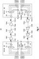
- FIG 1 schematically illustrates an example optical communications system 100 in which the principles described herein may be employed.
- information is communicated between terminals 101 and 102 via the use of optical signals.
- optical signals travelling from the terminal 101 to terminal 102 will be referred to as being “eastern”
- optical signals traveling from the terminal 102 to the terminal 101 will be referred to as being “western”.
- the terms “eastern” and “western” are simply terms of art used to allow for easy distinction between the two optical signals travelling in opposite directions.
- the use of the terms “eastern” and “western” does not imply any actual geographical relation of components in Figure 1 , nor to any actual physical direction of optical signals.
- terminal 101 may be geographical located eastward of the terminal 102, even though the convention used herein has “eastern” optical signals traveling from the terminal 101 to the terminal 102.
- the optical signals are Wavelength Division Multiplexed (WDM) and potentially Dense Wavelength Division Multiplexed (DWDM).
- WDM or DWDM information is communicated over each of multiple distinct optical channels called hereinafter "optical wavelength channels".
- Each optical wavelength channel is allocated a particular frequency for optical communication. Signals that fall within the particular frequency will be referred to as respective optical wavelength signals.
- the terminal 101 may have "n" optical transmitters 111 (including optical transmitters 111(1) through 111(n), where n is a positive integer), each optical transmitter for transmitting over a corresponding eastern optical wavelength channel.
- the terminal 102 may have "n" optical transmitters 121 including optical transmitters 121(1) through 121(n), each also for transmitting over a corresponding western optical wavelength channel.
- the principles described herein are not limited, however, to communications in which the number of eastern optical wavelength channels is the same as the number of western optical wavelength channels.
- the principles described herein are not limited to the precise structure of the each of the optical transmitters.
- lasers are an appropriate optical transmitter for transmitting at a particular frequency.
- the optical transmitters may be tunable within a frequency range.
- the terminal 101 multiplexes each of the eastern optical wavelength signals from the optical transmitters 111 into a single eastern optical signal using optical multiplexer 112 , which may then be optically amplified by an optional eastern optical amplifier 113 prior to being transmitted onto a first optical fiber link 114 (1) .
- the eastern optical signal from the final optical fiber link 114(m+1) is then optionally amplified at the terminal 102 by an optional optical amplifier 116 .
- the eastern optical signal is then demultiplexed into the various wavelength optical wavelength channels using optical demultiplexer 117.
- the various optical wavelength channels may then be received and processed by corresponding optical receivers 118 including optical receivers 118(1) through 118(n).
- the terminal 102 multiplexes each of the western optical wavelength signals from the optical transmitters 121 (including optical transmitters 121(1) through 121(n)) into a single western optical signal using the optical multiplexer 122 .
- the multiplexed optical signal may then be optically amplified by an optional western optical amplifier 123 prior to being transmitted onto a first optical fiber link 124(m+1). If the western optical channel is symmetric with the eastern optical channel, there are once again “m” repeaters 125 (labeled 125(1) through 125(m)), and "m+1" optical fiber links 124 (labeled 124(1) through 124(m+1)).
- the western optical signal from the final optical fiber link 124(1) is then optionally amplified at the terminal 101 by the optional optical amplifier 126 .
- the western optical signal is then demultiplexed using optical demultiplexer 127 , whereupon the individual wavelength division optical channels are received and processed by the optical receivers 128 (including optical receivers 128(1) through 128(n)).
- Terminals 101 and/or 102 do not require all the elements shown in optical communications system 100.
- optical amplifiers 113, 116, 123, and/or 126 might not be used in some configurations.
- each of the corresponding optical amplifiers 113, 116, 123 and/or 126 may be a combination of multiple optical amplifiers if desired.
- the optical path length between repeaters is approximately the same.
- the distance between repeaters will depend on the total terminal-to-terminal optical path distance, the data rate, the quality of the optical fiber, the loss-characteristics of the fiber, the number of repeaters (if any), the amount of electrical power deliverable to each repeater (if there are repeaters), and so forth.
- a typical optical path length between repeaters (or from terminal to terminal in an unrepeatered system) for high-quality single mode fiber might be about 50 kilometers, and in practice may range from 30 kilometers or less to 100 kilometers or more. That said, the principles described herein are not limited to any particular optical path distances between repeaters, nor are they limited to repeater systems in which the optical path distances are the same from one repeatered segment to the next.
- the optical communications system 100 is represented in simplified form for purpose of illustration and example only.
- the principles described herein may extend to much more complex optical communications systems.
- the principles described herein may apply to optical communication systems in which there are multiple fiber pairs, each for communicating multiplexed WDM optical signals.
- the principles described herein also apply to optical communications in which there are one or more branching nodes that split one or more fiber pairs and/or optical wavelength channels in one direction, and one or more fiber pairs and/or optical wavelength channels in another direction.
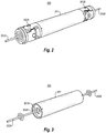
- Figure 2 illustrates a perspective view an example embodiment of an optical repeater 200 .
- the optical repeater 200 may perform amplification for one or more fiber pairs.
- the optical repeater 200 performs amplification for multiple fiber pairs.
- Each fiber pair includes a fiber for an eastern channel, and a fiber for a western channel.
- Figure 1 for example, only one eastern channel is illustrated (comprising optical fiber links 114(1) through 114(m+1) and repeaters 115(1) through 115(m)), and only one western channel is illustrated (comprising optical fiber links 124(1) through 124(m+1) and repeaters 125(1) through 125(m)).
- optical repeater 200 that is illustrated is just one example of a limitless variety of optical repeaters that may benefit from the broader principles described herein. Regardless of the shape or configuration of the optical repeater, the principles described herein allow the size of the repeater amplifier assembly to be adjusted so that a repeater amplifier assembly may be more easily removed from and inserted into the housing of the optical repeater. Nevertheless, the optical repeater 200 is an example that will now be described in further detail with respect to subsequent figures.
- the optical repeater 200 houses optical amplifiers inside a repeater housing 201 .
- the repeater housing 201 is cylindrical, although the principles described herein are not limited to that shape of repeater housing.
- the optical repeater 200 is a submarine repeater, though the principles described herein may also apply to terrestrial repeaters well.
- the repeater amplifier assembly includes the amplifiers themselves.
- the amplifiers may include rare earth element doped fibers together with powered semiconductor based optical pumps.
- the repeater housing 201 may be, for example, a metallic sea case that actually contacts the ambient ocean during operation.
- a cable is connected to each end of the optical repeater.
- the cable includes an electrical conductor for providing electrical power to and from the optical repeater 200, and also includes two optical fibers for each fiber pair supported by the optical repeater.
- a tail tube 202A is attached at one end of the optical repeater 200 (hereinafter also referred to as the "close end”) and connects the electrical conductor and optical fibers at that one end.
- another tail tube 202B is attached at the other end of the optical repeater 200 (hereinafter also referred to as the "far end”) and connects the electrical conductor and optical fibers at the other end.
- a bending-limiting device 203A is fitted to the close end of the repeater housing 201 and supports and guides the tail tube 202A.
- a similar bend-limiting device 203B is fitted to the far end of the repeater housing 201 and supports and guides tail tube 202B.
- Examples of a suitable bend-limiting devices are gimbals although the principles describe herein are not limited to the use of gimbals.
- the bend-limiting devices 203A and 203B limit the maximum bend seen by the tail tubes during deployment and recovery and the optical repeater 200, and allows the optical repeater 200 to articulate around a cable ship bow sheave.
- Each tail tube 202A and 202B is spliced to the cable and the resultant joint secured to the outboard end of the bend-limiting device.
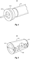
- Figure 3 illustrates a perspective view 300 of the optical repeater 200 of Figure 2 , except with the bend limiting devices 203A and 203B not shown so that several underlying components may be made visible.
- each end of the repeater housing 201 is sealed hermetically with a bulkhead 301A which is held in place by a retaining ring 302A .
- the sealing system is also designed to withstand hydrostatic pressure associated with deploying to water depths of up to 8km.
- the perspective view of Figure 3 shows this most clearly for the close end of the repeater housing 201, but a similar bulkhead and retaining ring may be present at the far end of the repeater housing 201 as well.
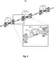
- Figure 4 illustrates a perspective view 400 of the close end of the optical repeater 200 of Figure 2 , except now with the bend-limiting device 203A and the repeater housing 201 not shown, so as to expose a close end of a liner 401 .
- the repeater amplifier assembly (not shown in Figure 4 , but shown more completely in Figure 5 ), is contained within the liner 401.
- the liner 401 serves as electrical isolation between the repeater amplifier assembly and the repeater housing 201.
- the repeater amplifier assembly generates heat.
- an intimate contact is best between the repeater amplifier assembly and the liner 401.
- the contact is very intimate, there will not be enough clearance between the repeater amplifier assembly and the liner 401 in order to facilitate assembly.
- the principles described herein solve these seemingly contradictory purposes by providing a repeater amplifier assembly that contracts and expands as desired. During assembly, when the repeater amplifier assembly is being inserted into the repeater housing, the repeater amplifier assembly may be in the contracted position to allow a clearance to freely insert the repeater amplifier assembly.
- the repeater amplifier assembly may be expanded to form the intimate contact with the liner. In some embodiments described herein, this expansive outward force is made to be tunable.
- the repeater amplifier assembly may be removed from the repeater housing by contracting the repeater amplifier assembly thereby forming the small clearance with the repeater housing, and thus facilitating removal of the repeater amplifier assembly from the repeater housing.
- Figure 5 illustrates a perspective view of a repeater amplifier assembly 500 that represents but one specific example of how such a contractible and expandable assembly may be formed.
- the repeater amplifier assembly 500 is suitable for a cylindrical housing and liner.
- other shapes of repeater amplifier assemblies may likewise be used for other repeater housing shapes, consistent with the principles described herein.
- repeater amplifier assemblies 500 There may be multiple repeater amplifier assemblies 500 stacked end-to-end lengthwise within the liner 401, although the liner 401 may also just contain one such repeater amplifier assembly 500.
- Figure 5 illustrates just one repeater amplifier assembly 500. In any case, the repeater housing 201 would be long enough to house the desired number of repeater amplifier assemblies.
- Each repeater amplifier assembly 500 includes two chassis 501 and 502.
- a size adjustment mechanism 510 connects the chassis 501 and 502, and is configured to adjust a size of the repeater amplifier assembly 500 by reversibly adjusting a position of the chassis 501 with respect to the chassis 502.
- the size adjustment mechanism 510 includes a control that allows the repeater amplifier assembly to be reversibly positioned in an expanded position in which the chassis 501 and 502 are pushed outward from each other, or a contracted position in which the chassis 501 and 502 are pulled inward towards each other. An example of this control will be described further below with respect to Figure 6A and Figure 6B .
- the chassis 501 includes optics and electronics such as, for example, the optics and electronics for at least one fiber pair.
- the chassis 502 also includes optics and electronics such as, for example, the optics and electronics for at least another fiber pair.
- optics and electronics might include, for example, the doped fiber amplifiers and electrically-powered pumps to.
- the chassis 501 and 502 each have an outward facing surface that is shaped as a length-wise portion (half) of a cylinder. This is suitable for a repeater housing that is cylindrically-shaped as such a surface would maintain intimate contact with such a repeater housing when the repeater amplifier assembly is inserted into the repeater housing and expanded.
- other shapes of chassis may be suitable to maintain intimate contact with other forms of repeater housing, consistent with the general principles described herein.
- the size adjustment mechanism 510 is designed to produce an outward force which maintains the intimate contact between the outer surface of the chassis 501 and 502 and the liner 401. This outward force is generated by an assembly of springs and linkages as shown in Figures 6A and 6B .
- the springs or other resilient compression mechanism produce a load on reaction blocks which forces the reaction blocks apart.
- Link arms transfer this load to the chassis, pushing the chassis outwards.
- the applied outward force is maintained over time to a level that allows the intimate contact to be maintained until the optical repeater is next maintained or until the optical repeater reaches its end of lifetime.
- the outward force may be maintained consistently over time, so that it does not significantly relax over time.
- the outward force may be made to be tunable.
- Figure 6A illustrates a perspective close-up view on the size adjustment mechanism 510 in an expanding state 600A.
- Figure 6B illustrates a perspective close-up view on the size adjustment mechanism 510 in contracting state 600B.
- the size adjustment mechanism 510 includes a guide rod 601 that is left hand threaded on one end, and right hand threaded at the other end.
- One guide piece 602A is threaded on the left hand threaded portion, and a guide piece 602B is threaded on the right hand threaded portion.
- the size adjustment mechanism 510 includes a mechanism for permitting the guide rod 601 to be rotated with respect to the guide pieces 602A and 602B.
- the size adjustment mechanism 510 includes reaction block 603A slidably coupled to the guide rod 601, and another reaction block 603B slidably coupled to the guide rod 601.
- the size adjustment mechanism 510 also includes a resilient compression mechanism 604 coupled to urge the reaction blocks 603A and 603B apart along the guide rod 601.
- the resilient compression mechanism 604 may be a spring positioned on the guide rod 601 between the reaction blocks 603A and 603B.
- the resilience compression mechanism 604 is a series of stacked disk springs and perhaps spacers.
- the level of push-out force can be varied by altering the geometry of the mechanism and characteristics/arrangement of the springs.
- the springs can be selected to achieve a force that is suitable for requirements such as optimal thermal contact and secure axial location/retention of the repeater amplifier assembly within the housing (e.g., which could be a sea case if deployed in a submarine repeater).
- the push out force is not sensitive to the operator variance or error during assembly that may occur with a rigid push-out system that jacks the chassis outwards until, perhaps, a torque limit is reached.
- the forces that are exerted by the size adjustment mechanism can be pre-set by careful engineering of geometry and selection of the springs' physical parameters. A reliable, repeatable, level of force can therefore be pre-determined.
- the repeater amplifier assembly allows for small dimensional variances in housing internal diameter from one repeater to another due to normal manufacturing tolerances. Exerting a force by means of springs results in a mechanism that will self-adjust to the internal diameter of the liner. In additional during the repeaters lifetime small diametrical dimensional changes may occur as a consequence of phenomena such as thermal expansion, hydrostatic compression and material creep.
- the spring forces are broadly linear over the small movement range and so the internal unit is able to self-adjust whilst delivering a relatively constant push-out force, thereby providing a significant improvement to the art of optical repeaters.
- the size adjustment mechanism 510 also includes a force transfer mechanism configured to transfer output pressure on the chassis 501 and 502 when the reaction blocks 603A and 603B are moved further apart along the guide rod 601.
- a force transfer mechanism is link arms 621 through 624 .
- Link arm 621 is coupled between the reaction block 603A and the chassis 501.
- Link arm 622 is coupled between the reaction block 603B and the chassis 501.
- Link arm 623 is coupled between the reaction block 603A and the chassis 502.
- Link arm 624 is coupled between the reaction block 603B and the chassis 502.
- the guide rod 601 With the guide rod 601 rotatably coupled to the end pieces 511 and 512, and with the size adjustment mechanism 510 configured as shown and described with respect to Figures 6A and 6B , the guide rod 601 may be rotated with respect to the guide pieces 602A and 602B since the guide pieces 602A and 602B are held by the respective reaction blocks 603A and 603B.
- the guide piece 602A thus pushes the reaction block 603A against the resilient compression mechanism 604, and the guide piece 602B thus pushes the reaction block 603B against the resilient compression mechanism 604.
- the force transfer mechanism With the reaction blocks 603A and 603B moving closer together, the force transfer mechanism thus pulls inward on the chassis 501 and 502.
- link arms 621 through 624 pull inwards on the chassis 501 and 502 are represented by the arrows 631B , 632B , 633B and 634B , thereby causing a contracting action of the repeater amplifier assembly.
- the repeater amplifier assembly 500 collapses to a state where it can be inserted into the repeater housing 201 (or more specifically, into the liner 401 set within the repeater housing 201).
- the reaction blocks 603A and 603B are locked in position so that no externally applied rotational force need be applied to the guide rod in order to keep the first and second reaction blocks in place.
- the guide rod 601 may be rotated in the opposite direction 610A as illustrated in Figure 6A .
- This causes the guide pieces 602A and 602B to move further apart along the guide rod 601.
- Due to the force of the resilient compression mechanism 604 this also causes the reaction blocks 603A and 603B to move further apart along the guide rod 601.
- a force transfer mechanism is configured to transfer outward pressure on the chassis 501 and 502 when the reaction blocks 603A and 603B are moved further apart along the guide rod 601.
- the repeater amplifier assembly 500 expands. Once the chassis 501 and 502 have reached the liner 401, continued rotation causes the guide rod 601 and captive guide pieces 602A and 602B to become loose. The outward load is then fully controlled by the resilient compression mechanism 604.
- some embodiments allow the outward force of the chassis to be sufficient to cause the chassis to make intimate contact with the repeater housing. This provides an efficient thermal channel for dissipating heat from the optics and electronics on the chassis through the housing. In the case of a submarine repeater, the cold ocean would serve as an effective heat sink in that case.
- the principles described herein are not limited to the form of the repeater amplifier assembly.
- the principles described herein are also not limited to the manner or mechanism used to expand and contract the repeater amplifier assembly.
- the repeater amplifier assembly has some type of control that allows the repeater amplifier assembly to be reversibly positioned in an expanded position in which the chassis are pushed outward from each other, or a contracted position in which the chassis are pulled inward towards each other.
- an example of this control is the rotation of the guide rod 601.
- Figure 7 illustrates a cross-sectional view 700 of the repeater amplifier assembly 500 of Figure 5 within the housing 201 of Figure 2 .
- the axes of the guide rods 601(1) and 601(2) and the repeater amplifier assembly 500 are coplanar.
- the size adjustment mechanisms 510(1) and 510(2) are located symmetrically about the axis of the repeater amplifier assembly 500.
- End plate devices are used to control the co-planarity of the guide rods 601(1) and 602(2). They also serve to restrict the amount of internal unit compression and expansion around the nominal 'steady-state' diameter which is the same as the inner diameter of the liner 401. Restriction of expansion only applies when the repeater amplifier assembly 500 is de-housed. When housed inside the housing (e.g., a sea case if a submarine repeater), the liner 401 acts as the expansion limiter. The final function of the end plate devices is to ensure that the end faces of chassis 501 and 502 remain coplanar. Without the end plates, very small imbalances in the mechanism would tend to distort the repeater amplifier assembly into a trapezoidal shape and prevent correct operation.
- each chassis 501 or 502 is capable of handling the optical functions for a single fiber pair.
- the repeater amplifier assembly 500 having two chassis 501 and 502, handles optical functions for two fiber pairs.
- the design may be expanded to handle more fiber pairs by, for example, including the optical functioning for more than one fiber pair in each chassis 501 and 502, or (as will now be described) concatenating multiple instances of the repeater amplifier assembly 500 together.
- Figure 8A illustrates a series assembly 800A of two concatenated instances 500(1) and 500(2) of the repeater amplifier assembly 500 of Figure 5 .
- Figure 8B illustrates a series assembly 800B of three concatenated instances 500(1), 500(2) and 500(3) of the repeater amplifier assembly 500 of Figure 5 .
- the design of the housing 201 would be lengthened to accommodate the increased length of the concatenated series 800A and 800B.
- the principles may be further extended to concatenations of more than three repeater amplifier assemblies as well.
- the actuation of the size adjustment mechanisms could be achieved by accessing the first repeater amplifier assembly 500(1) from one end of the housing 201 and then the second repeater amplifier assembly 500(2) from the other end of the housing 201.
- this principle does not extend to an internal unit of five or more fiber pairs (a series 800B of three concatenated repeater amplifier assemblies 500(1), 500(2) and 500(3)) as the design would not allow for actuation of the central repeater amplifier assembly 500(2) of Figure 8B unless the rotation of their guide rods were to be driven by a connection to an adjacent repeater amplifier assembly 500(1) or 500(3) of Figure 8B .
- This connection should allow for some independent axial movement in the rods whilst maintaining secure rotational connectivity.
- Figure 9 illustrates a structure 900 that would allow this.
- one of the size adjustment mechanisms 510(1), 510(2) and 510(3) for each of the corresponding repeater amplifier assemblies 500(1), 500(2) and 500(3) of the series 800B of Figure 8B are shown.
- the connection between the size adjustment mechanism 510(1) and 510(2) is shown.
- the guide rod of the size adjustment mechanism 510(1) has a hex drive at its end that may be received into and removed from (as represented by arrow 903 ) a hex socket within the opposing end of the next guide rod of the next size adjustment mechanism 510(2).
- the series should be completed with each mechanism in a compressed state (i.e., with captive guide blocks in contact with reaction blocks).
- the nominal compression level should be the same for all repeater amplifier assemblies but tolerances will dictate some variability in the level of compression. There should be sufficient travel to further compress the repeater amplifier assembly chain to facilitate assembly into the housing.
- each repeater amplifier assembly After insertion, the guide rods are rotated to transfer load control to the resilient compression mechanism. Each repeater amplifier assembly will then move to achieve its fully pushed out position. For instance, in the case of Figure 8B , one repeater amplifier assembly will achieve push-out, then the second repeater amplifier assembly, and then the third repeater amplifier assembly before the guide rods become slack. The exact order depends on part and assembly tolerances. It is likely to vary from repeater to repeater but will not affect functionality.
- Figure 10 illustrates a flowchart of a method 1000 for inserting a repeater amplifier assembly into a repeater housing.
- the method 1000 may be performed in inserting the repeater amplifier assembly 500 into the repeater housing 201.
- the method 1000 will be described with frequent reference to Figures 2 through 8B .
- a repeater amplifier assembly is accessed in a contracted position (act 1001 ).
- the guide rod 601 may be rotated in direction 610B until the repeater amplifier assembly 500 (in the case of Figure 5 ) or the series 800A or 800B of repeater amplifier assemblies (in the case of Figures 8A and 8B ) is contracted.
- the repeater amplifier assembly is then inserted in a repeater housing (act 1002 ).
- the contracted repeater amplifier assembly 500 (or the series 800A and 800B) may be inserted into repeater housing 201 and liner 401.
- a control is then actuated to cause the repeater amplifier assembly or series thereof to expand against the housing (act 1003 ).
- the guide rod 601 may be rotated in direction 610A to cause the chassis 501 and 502 to press against the liner 401 inside the repeater housing 201.
- the rotation of the shared guide rod may cause the series 800A or 800B to press against the liner 401 inside the repeater housing 201.
- Figure 11 illustrates a flowchart of a method 1100 for removing a repeater amplifier assembly from a repeater housing.
- a repeater housing is accessed (act 1101 ).
- the repeater housing may be accessed from the ocean floor.
- a control is actuated to cause the repeater amplifier assembly to contract (act 1102 ).
- the guide rod 601 may be rotated in direction 610A to cause the chassis 501 and 502 to no longer press against the repeater housing 201.
- all of the chassis may disengage from the repeater housing 201.
- the repeater amplifier assembly or series thereof is then removed from the repeater housing (act 1102 ).
- the repeater amplifier assembly 500 or the series 800A or 800B may then be freely removed from the liner 401 and repeater housing 201.
- the principles described herein describe a mechanism for expanding and contracting a repeater amplifier assembly so that the assembly can be more freely inserted and removed from the repeater housing.
Landscapes
- Physics & Mathematics (AREA)
- Engineering & Computer Science (AREA)
- Computer Networks & Wireless Communication (AREA)
- Signal Processing (AREA)
- Electromagnetism (AREA)
- General Physics & Mathematics (AREA)
- Optics & Photonics (AREA)
- Optical Communication System (AREA)
- Light Guides In General And Applications Therefor (AREA)
Claims (15)
- Repeaterverstärkerbaugruppe (500), umfassend:ein erstes Chassis (501), das eine erste Optik und Elektronik enthält;ein zweites Chassis (502), das eine zweite Optik und Elektronik enthält; undeinen Größeneinstellmechanismus (510), der das erste und das zweite Chassis (501, 502) verbindet, und ausgelegt ist zum Einstellen einer Größe der Repeaterverstärkerbaugruppe (500) durch reversibles Einstellen einer Position des ersten Chassis (501) in Bezug auf das zweite Chassis (502);dadurch gekennzeichnet, dass der Größeneinstellmechanismus (510) einen ersten Mechanismus umfasst, der Folgendes aufweist:eine Führungsstange (601), die an einer ersten Position mit einem Linksgewinde versehen ist und an einer zweiten Position mit einem Rechtsgewinde versehen ist;ein erstes Führungsstück (602A), das auf den Linksgewindeabschnitt aufgeschraubt ist;ein zweites Führungsstück (602B), das auf den Rechtsgewindeabschnitt aufgeschraubt ist,einen Mechanismus, der es der Führungsstange (601) ermöglicht, mit Bezug auf das erste und das zweite Führungsstück (602A, 602B) gedreht zu werden, so dass, wenn die Führungsstange (601) in einer ersten Richtung gedreht wird, das erste und das zweite Führungsstück (602A, 602B) entlang der Führungsstange (601) dichter zusammenrücken, und so dass, wenn die Führungsstange (601) in einer zweiten Richtung gedreht wird, das erste und das zweite Führungsstück (602A, 602B) entlang der Führungsstange (601) weiter auseinander rücken;einen ersten Reaktionsblock (603A), der verschiebbar mit der Führungsstange (601) gekoppelt ist;einen zweiten Reaktionsblock (603B), der auch verschiebbar mit der Führungsstange (601) gekoppelt ist;einen nachgiebigen Kompressionsmechanismus (604), gekoppelt zum Auseinandertreiben des ersten und des zweiten Reaktionsblocks (603A, 603B) entlang der Führungsstange (601), wobei, wenn sich das erste und das zweite Führungsstück (602A, 602B) entlang der Führungsstange (601) dichter zusammenbewegen, das erste und das zweite Führungsstück (602A 602B) den ersten und den zweiten Reaktionsblock (603A, 603B) zwingen, sich entlang der Führungsstange (601) dichter zusammenzuschieben und den nachgiebigen Kompressionsmechanismus (604) zusammendrücken und wobei, wenn sich das erste und das zweite Führungsstück (602A, 602B) entlang der Führungsstange (601) weiter voneinander wegbewegen, das erste und das zweite Führungsstück (602A, 602B) es dem nachgiebigen Kompressionsmechanismus (604) erlauben, den ersten und den zweiten Reaktionsblock (603A, 603B) derart zu stoßen, dass sie entlang der Führungsstange (601) weiter voneinander entfernt gestoßen werden; undeinen Kraftübertragungsmechanismus, der ausgelegt ist zum Übertragen von Ausgangsdruck auf das erste und das zweite Chassis (501, 502), wenn der erste und der zweite Reaktionsblock (603A, 603B) entlang der Führungsstange (601) weiter voneinander weg bewegt werden, und ausgelegt ist zum Einziehen an dem ersten und dem zweiten Chassis (501, 502), wenn der erste und der zweite Reaktionsblock (603A, 603B) entlang der Führungsstange (601) dichter zueinander bewegt werden.
- Repeaterverstärkerbaugruppe (500) nach Anspruch 1, wobei die erste Optik und Elektronik für mindestens ein erstes Faserpaar bestimmt ist und, optional, wobei die zweite Optik und Elektronik für mindestens ein zweites Faserpaar bestimmt ist.
- Repeaterverstärkerbaugruppe (500) nach Anspruch 1, wobei das erste Chassis (501) eine außenweisende Oberfläche aufweist, die als ein Längsabschnitt eines Zylinders ausgebildet ist, und wobei das zweite Chassis (502) auch eine außenweisende Oberfläche aufweist, die auch als ein Längsabschnitt eines Zylinders ausgebildet ist.
- Repeaterverstärkerbaugruppe (500) nach Anspruch 1, wobei, wenn sich das erste und das zweite Führungsstück (602A, 602B) entlang der Führungsstange (601) dichter zueinander jenseits eines gewissen Punkts bewegen, der erste und der zweite Reaktionsblock (603A, 603B) in Position verriegelt werden, so dass keine extern ausgeübte Drehkraft auf die Führungsstange (601) ausgeübt werden muss, um den ersten und den zweiten Reaktionsblock (603A, 603B) an der Stelle zu halten.
- Repeaterverstärkerbaugruppe (500) nach Anspruch 1, wobei der Kraftübertragungsmechanismus einen zwischen den ersten Reaktionsblock (603A) und das erste Chassis (501) gekoppelten ersten Verbindungsarm (621) umfasst.
- Repeaterverstärkerbaugruppe (500) nach Anspruch 5, wobei der Kraftübertragungsmechanismus einen zwischen den ersten Reaktionsblock (603A) und das zweite Chassis (502) gekoppelten zweiten Verbindungsarm (623) umfasst.
- Repeaterverstärkerbaugruppe (500) nach Anspruch 6, wobei der Kraftübertragungsmechanismus ferner Folgendes umfasst:einen zwischen den zweiten Reaktionsblock (603B) und das erste Chassis (501) gekoppelten dritten Verbindungsarm (622); undeinen zwischen den zweiten Reaktionsblock (603B) und das zweite Chassis (502) gekoppelten vierten Verbindungsarm (624).
- Repeaterverstärkerbaugruppe (500) nach Anspruch 1, wobei der Größeneinstellmechanismus (510) einen zweiten Mechanismus (510(B)) aufweist, wobei die Führungsstange (601) eine erste Führungsstange ist, der nachgiebige Kompressionsmechanismus (504) ein erster nachgiebiger Kompressionsmechanismus (504) ist und der Kraftübertragungsmechanismus (510) ein erster Kraftübertragungsmechanismus (510(A)) ist, wobei der zweite Mechanismus (510(B)) Folgendes umfasst:eine zweite Führungsstange (601), die an einer ersten Position mit einem Linksgewinde versehen ist und an einer zweiten Position mit einem Rechtsgewinde versehen ist;ein drittes Führungsstück (602A), das auf den Linksgewindeabschnitt aufgeschraubt ist;ein viertes Führungsstück (602B), das auf den Rechtsgewindeabschnitt aufgeschraubt ist,einen Mechanismus, der es der zweiten Führungsstange (601) ermöglicht, mit Bezug auf das dritte und das vierte Führungsstück (602A, 602B) gedreht zu werden, so dass, wenn die zweite Führungsstange (601) in einer ersten Richtung gedreht wird, das dritte und das vierte Führungsstück (602A, 602B) entlang der zweiten Führungsstange (601) dichter zusammenrücken, und so dass, wenn die zweite Führungsstange (601) in einer zweiten Richtung gedreht wird, das dritte und das vierte Führungsstück (602A, 602B) entlang der zweiten Führungsstange (601) weiter auseinander rücken;einen dritten Reaktionsblock (603A), der verschiebbar mit der zweiten Führungsstange (601) gekoppelt ist;einen vierten Reaktionsblock (603B), der auch verschiebbar mit der zweiten Führungsstange (601) gekoppelt ist;einen zweiten nachgiebigen Kompressionsmechanismus (604), gekoppelt zum Auseinandertreiben des dritten und des vierten Reaktionsblocks (603A, 603B) entlang der zweiten Führungsstange (601), wobei, wenn sich das dritte und das vierte Führungsstück (602A, 602B) entlang der zweiten Führungsstange (601) dichter zusammenbewegen, das dritte und das vierte Führungsstück (602A, 602B) den dritten und den vierten Reaktionsblock (603A, 603B) zwingen, sich entlang der zweiten Führungsstange (601) dichter zusammenzuschieben und den zweiten nachgiebigen Kompressionsmechanismus (604) zusammendrücken und wobei, wenn sich das dritte und das vierte Führungsstück (602A, 602B) entlang der zweiten Führungsstange (601) weiter voneinander wegbewegen, das dritte und das vierte Führungsstück (602A, 602B) es dem zweiten nachgiebigen Kompressionsmechanismus (604) erlauben, den dritten und den vierten Reaktionsblock (603A, 603B) derart zu stoßen, dass sie entlang der zweiten Führungsstange (601) weiter voneinander entfernt gestoßen werden; und einen zweiten Kraftübertragungsmechanismus, der ausgelegt ist zum Übertragen von Ausgangsdruck auf das erste und das zweite Chassis (501, 502), wenn der dritte und der vierte Reaktionsblock (603A, 603B) entlang der zweiten Führungsstange (601) weiter voneinander weg bewegt werden, und ausgelegt ist zum Einziehen an dem ersten und dem zweiten Chassis (501, 502), wenn der dritte und der vierte Reaktionsblock (603A, 603B) entlang der zweiten Führungsstange (601) dichter zueinander bewegt werden.
- Repeaterverstärkerbaugruppe (500) nach Anspruch 1, wobei der nachgiebige Kompressionsmechanismus (604) eine Feder oder eine Reihe von Federscheiben ist, positioniert auf der Führungsstange (601) zwischen dem ersten und dem zweiten Reaktionsblock (603A, 603B).
- Repeaterverstärkerbaugruppe (500) nach Anspruch 1, ferner umfassend:ein drittes Chassis, das eine dritte Optik und Elektronik enthält;ein viertes Chassis, das eine vierte Optik und Elektronik enthält; undeinen zweiten Größeneinstellmechanismus (510(2)), der das dritte und das vierte Chassis verbindet, und ausgelegt ist zum Einstellen einer Größe der Repeaterverstärkerbaugruppe (500) durch reversibles Einstellen einer Position des dritten Chassis in Bezug auf das vierte Chassis.
- Repeaterverstärkerbaugruppe nach Anspruch 10, wobei der erste und der zweite Größeneinstellmechanismus (510(1), 510(2)) derart verbunden sind, dass die Position des ersten Chassis in Bezug auf das zweite Chassis reversibel eingestellt wird, während die reversible Einstellung der Position des dritten Chassis in Bezug auf das vierte Chassis stattfindet.
- Verfahren zum Einsetzen einer Repeaterverstärkerbaugruppe (500) nach Anspruch 1 in ein Repeatergehäuse (201), umfassend:Zugreifen auf eine Repeaterverstärkerbaugruppe (500) in einer kontrahierten Position;Einsetzen der Repeaterverstärkerbaugruppe (500) in ein Repeatergehäuse (201); undBetätigen der Führungsstange (601), um den Größeneinstellmechanismus zu veranlassen, das erste und das zweite Chassis (501, 502) zu zwingen, sich nach außen auszudehnen, bis das erste und das zweite Chassis (501, 502) gegen das Repeatergehäuse (201) anstoßen.
- Verfahren nach Anspruch 12, wobei das Repeatergehäuse (201) ein seefester Behälter ist.
- Verfahren nach Anspruch 12, wobei der Vorgang des Zugreifens auf eine Repeaterverstärkerbaugruppe (500) in einer kontrahierten Position Folgendes umfasst:Zugreifen auf die Repeaterverstärkerbaugruppe (500) in einer ausgedehnten Position, wobei der Größeneinstellmechanismus das erste und das zweite Chassis (501, 502) voneinander weggeschoben hat; undBetätigen der Führungsstange (601), um den Größeneinstellmechanismus zu veranlassen, das erste und das zweite Chassis (501, 502) zu zwingen, sich nach innen zu ziehen, bis sich die Repeaterverstärkerbaugruppe (500) in der kontrahierten Position befindet.
- Verfahren zum Entfernen einer Repeaterverstärkerbaugruppe (500) nach Anspruch 1 aus einem Repeatergehäuse (201), umfassend:einen Vorgang des Zugreifens auf ein Repeatergehäuse (201), das darin befindlich eine Repeaterverstärkerbaugruppe (500) in einer ausgedehnten Position aufweist;einen Vorgang des Betätigens der Führungsstange (601), um den Größeneinstellmechanismus zu veranlassen, das erste und das zweite Chassis (501, 502) zu veranlassen, sich nach innen zu ziehen, bis das erste und das zweite Chassis (501, 502) nicht mehr gegen das Repeatergehäuse (201) anstoßen; undeine Handlung des Entfernens der Repeaterverstärkerbaugruppe (500) aus dem Repeatergehäuse (201).
Applications Claiming Priority (2)
| Application Number | Priority Date | Filing Date | Title |
|---|---|---|---|
| US13/742,076 US9094127B2 (en) | 2013-01-15 | 2013-01-15 | Optical repeater amplifier insertion and removal technology |
| PCT/US2014/011593 WO2014113422A1 (en) | 2013-01-15 | 2014-01-15 | Optical repeater amplifier insertion and removal technology |
Publications (2)
| Publication Number | Publication Date |
|---|---|
| EP2946239A1 EP2946239A1 (de) | 2015-11-25 |
| EP2946239B1 true EP2946239B1 (de) | 2019-02-27 |
Family
ID=50031609
Family Applications (1)
| Application Number | Title | Priority Date | Filing Date |
|---|---|---|---|
| EP14702391.5A Active EP2946239B1 (de) | 2013-01-15 | 2014-01-15 | Technik zum einschieben und herausnehmen einer optischen relais verstärkerstation |
Country Status (4)
| Country | Link |
|---|---|
| US (2) | US9094127B2 (de) |
| EP (1) | EP2946239B1 (de) |
| JP (1) | JP6453237B2 (de) |
| WO (1) | WO2014113422A1 (de) |
Families Citing this family (6)
| Publication number | Priority date | Publication date | Assignee | Title |
|---|---|---|---|---|
| GB2536603B (en) * | 2014-10-07 | 2021-02-17 | Aker Solutions Ltd | Subsea electronic device |
| US9559776B2 (en) | 2015-01-21 | 2017-01-31 | Google Inc. | Locally powered optical communication network |
| USD769230S1 (en) * | 2015-01-22 | 2016-10-18 | Samsung Electronics Co., Ltd. | Optical repeater |
| US20170170910A1 (en) | 2015-12-14 | 2017-06-15 | Nikola Alic | Increase in reach of unrepeatered fiber transmission |
| EP3598668A4 (de) * | 2017-03-17 | 2020-03-18 | Nec Corporation | Optisches unterwasserkabelsystem und optische unterwasserrelaisvorrichtung |
| CN113825341B (zh) * | 2021-11-24 | 2022-03-01 | 华海通信技术有限公司 | 一种承压舱内部单元的涨紧机构 |
Family Cites Families (9)
| Publication number | Priority date | Publication date | Assignee | Title |
|---|---|---|---|---|
| US4528615A (en) | 1983-05-13 | 1985-07-09 | At&T Bell Laboratories | Repeater housing and circuit mounting structure |
| DE4207375C2 (de) | 1992-03-09 | 1994-10-27 | Mhp Mannesmann Hoesch Praezisr | Kupplung für das zeitweise koaxiale Verbinden von Einzelrohren |
| US6292556B1 (en) | 1997-11-06 | 2001-09-18 | Anacapa Technology, Inc. | Local loop telecommunication repeater housings employing thermal collection, transfer and distribution via solid thermal conduction |
| US6411414B1 (en) * | 1998-11-19 | 2002-06-25 | Lucent Technologies Inc. | Wavelength division multiplexing wireless optical link |
| JP3324592B2 (ja) * | 2000-01-31 | 2002-09-17 | 日本電気株式会社 | 海底中継器ユニットおよび海底中継器 |
| US6707670B2 (en) | 2001-09-12 | 2004-03-16 | Dorsal Networks, Inc. | Systems and methods for mounting devices |
| US6870993B2 (en) * | 2002-12-13 | 2005-03-22 | Red Sky Systems, Inc. | Interconnect including a repeater for an optical transmission cable |
| JP2011501549A (ja) * | 2007-10-16 | 2011-01-06 | エクステラ コミュニケーションズ リミティド | 位相シフトキーイング高速度シグナリング |
| US8849122B2 (en) * | 2012-04-19 | 2014-09-30 | Time Warner Cable Enterprises, LLC | Apparatus and methods for dynamic delivery of optical and non-optical content in a network |
-
2013
- 2013-01-15 US US13/742,076 patent/US9094127B2/en active Active
-
2014
- 2014-01-15 EP EP14702391.5A patent/EP2946239B1/de active Active
- 2014-01-15 JP JP2015552910A patent/JP6453237B2/ja active Active
- 2014-01-15 WO PCT/US2014/011593 patent/WO2014113422A1/en not_active Ceased
-
2015
- 2015-02-12 US US14/621,183 patent/US9184848B2/en active Active
Non-Patent Citations (1)
| Title |
|---|
| None * |
Also Published As
| Publication number | Publication date |
|---|---|
| JP6453237B2 (ja) | 2019-01-16 |
| JP2016505900A (ja) | 2016-02-25 |
| US20150155943A1 (en) | 2015-06-04 |
| EP2946239A1 (de) | 2015-11-25 |
| US20140199083A1 (en) | 2014-07-17 |
| WO2014113422A1 (en) | 2014-07-24 |
| US9184848B2 (en) | 2015-11-10 |
| US9094127B2 (en) | 2015-07-28 |
Similar Documents
| Publication | Publication Date | Title |
|---|---|---|
| US9184848B2 (en) | Optical repeater amplifier insertion and removal technology | |
| US8335428B2 (en) | Method and system for protection switching | |
| US5812306A (en) | Bidirectional WDM optical communication systems with bidirectional optical amplifiers | |
| US20100008666A1 (en) | Optical Communication System Supporting Detection and Communication Networks | |
| WO2002033446A3 (en) | Method and system for high channel capacity wave division multiplexer and de-multiplexer using reflective and transmission holographic methodologies for optical communications and the like | |
| CN103959717B (zh) | 用于分支型光网络中的故障恢复的方法和系统 | |
| US20120294604A1 (en) | Optical protection and switch enabled optical repeating | |
| US7034994B2 (en) | Dispersion management for long-haul high-speed optical networks | |
| US20180241469A1 (en) | Feedback controlled raman amplification in optical system | |
| US20090285584A1 (en) | Unrepeatered optical segment for use with repeatered series of optical segments | |
| CN106464381B (zh) | 具有远程光学泵浦式放大器的多区段光通信链路 | |
| Downie et al. | Long-haul transmission over ultra-low attenuation and crosstalk 4-core multicore fiber | |
| CN111294114B (zh) | 光通信节点、中继节点和光通信系统 | |
| JP2012501477A (ja) | より大きな有効面積を遠位部に有する光ファイバ | |
| US20260051966A1 (en) | WIDEBAND HOLLOW CORE TRANSMISSION FIBER AND DWDM LIGHTWAVE TRANSMISSION SYSTEM IN THE 2000 nm WAVELENGTH REGION | |
| US20170126317A1 (en) | Single module bi-directional optical transmitting and receiving system | |
| Cui et al. | Real-Time 142.65 Pb/s· km Transmission Capability Field Demonstration Over Deployed 7-Core Fiber Cable with Multiple Fusion Splicing | |
| Turukhin et al. | High-capacity SDM transmission over transoceanic distances | |
| Zhu et al. | Advanced Low-Loss Fibers for High-Capacity Transmission: from Data Center to Undersea | |
| JP3411962B2 (ja) | 海底光ケーブル接続函 | |
| Chang et al. | First Demonstration of Real-time 0.67 Pb/s Transmission over 356-km 7-Core Fiber using 135-Gbaud C+ L-band 1.2 Tb/s OTN Transponders | |
| JP2023537875A (ja) | 地上中継器及び最適化された中継器間隔 | |
| Yamamoto et al. | Simultaneous 3× 10-Gbps optical data transmission in 1-µm, C-, and L-wavebands over a single holey fiber for ultrabroad-waveband photonic transport system | |
| Charlet | Polarization division multiplexing solution for submarine application at 40Gb/s and 100Gb/s | |
| Oyemomi | An Overview of Fibre Optics Technology and Design: Undersea Cable Systems |
Legal Events
| Date | Code | Title | Description |
|---|---|---|---|
| PUAI | Public reference made under article 153(3) epc to a published international application that has entered the european phase |
Free format text: ORIGINAL CODE: 0009012 |
|
| 17P | Request for examination filed |
Effective date: 20150703 |
|
| AK | Designated contracting states |
Kind code of ref document: A1 Designated state(s): AL AT BE BG CH CY CZ DE DK EE ES FI FR GB GR HR HU IE IS IT LI LT LU LV MC MK MT NL NO PL PT RO RS SE SI SK SM TR |
|
| AX | Request for extension of the european patent |
Extension state: BA ME |
|
| DAX | Request for extension of the european patent (deleted) | ||
| RAP1 | Party data changed (applicant data changed or rights of an application transferred) |
Owner name: NEPTUNE SUBSEA IP LIMITED |
|
| GRAP | Despatch of communication of intention to grant a patent |
Free format text: ORIGINAL CODE: EPIDOSNIGR1 |
|
| STAA | Information on the status of an ep patent application or granted ep patent |
Free format text: STATUS: GRANT OF PATENT IS INTENDED |
|
| INTG | Intention to grant announced |
Effective date: 20180828 |
|
| GRAJ | Information related to disapproval of communication of intention to grant by the applicant or resumption of examination proceedings by the epo deleted |
Free format text: ORIGINAL CODE: EPIDOSDIGR1 |
|
| STAA | Information on the status of an ep patent application or granted ep patent |
Free format text: STATUS: REQUEST FOR EXAMINATION WAS MADE |
|
| GRAR | Information related to intention to grant a patent recorded |
Free format text: ORIGINAL CODE: EPIDOSNIGR71 |
|
| GRAS | Grant fee paid |
Free format text: ORIGINAL CODE: EPIDOSNIGR3 |
|
| STAA | Information on the status of an ep patent application or granted ep patent |
Free format text: STATUS: GRANT OF PATENT IS INTENDED |
|
| GRAA | (expected) grant |
Free format text: ORIGINAL CODE: 0009210 |
|
| STAA | Information on the status of an ep patent application or granted ep patent |
Free format text: STATUS: THE PATENT HAS BEEN GRANTED |
|
| INTC | Intention to grant announced (deleted) | ||
| AK | Designated contracting states |
Kind code of ref document: B1 Designated state(s): AL AT BE BG CH CY CZ DE DK EE ES FI FR GB GR HR HU IE IS IT LI LT LU LV MC MK MT NL NO PL PT RO RS SE SI SK SM TR |
|
| INTG | Intention to grant announced |
Effective date: 20190122 |
|
| REG | Reference to a national code |
Ref country code: GB Ref legal event code: FG4D |
|
| REG | Reference to a national code |
Ref country code: CH Ref legal event code: EP |
|
| REG | Reference to a national code |
Ref country code: DE Ref legal event code: R096 Ref document number: 602014041746 Country of ref document: DE |
|
| REG | Reference to a national code |
Ref country code: AT Ref legal event code: REF Ref document number: 1102208 Country of ref document: AT Kind code of ref document: T Effective date: 20190315 |
|
| REG | Reference to a national code |
Ref country code: IE Ref legal event code: FG4D |
|
| REG | Reference to a national code |
Ref country code: NL Ref legal event code: MP Effective date: 20190227 |
|
| REG | Reference to a national code |
Ref country code: LT Ref legal event code: MG4D |
|
| PG25 | Lapsed in a contracting state [announced via postgrant information from national office to epo] |
Ref country code: LT Free format text: LAPSE BECAUSE OF FAILURE TO SUBMIT A TRANSLATION OF THE DESCRIPTION OR TO PAY THE FEE WITHIN THE PRESCRIBED TIME-LIMIT Effective date: 20190227 Ref country code: NO Free format text: LAPSE BECAUSE OF FAILURE TO SUBMIT A TRANSLATION OF THE DESCRIPTION OR TO PAY THE FEE WITHIN THE PRESCRIBED TIME-LIMIT Effective date: 20190527 Ref country code: NL Free format text: LAPSE BECAUSE OF FAILURE TO SUBMIT A TRANSLATION OF THE DESCRIPTION OR TO PAY THE FEE WITHIN THE PRESCRIBED TIME-LIMIT Effective date: 20190227 Ref country code: SE Free format text: LAPSE BECAUSE OF FAILURE TO SUBMIT A TRANSLATION OF THE DESCRIPTION OR TO PAY THE FEE WITHIN THE PRESCRIBED TIME-LIMIT Effective date: 20190227 Ref country code: PT Free format text: LAPSE BECAUSE OF FAILURE TO SUBMIT A TRANSLATION OF THE DESCRIPTION OR TO PAY THE FEE WITHIN THE PRESCRIBED TIME-LIMIT Effective date: 20190627 Ref country code: FI Free format text: LAPSE BECAUSE OF FAILURE TO SUBMIT A TRANSLATION OF THE DESCRIPTION OR TO PAY THE FEE WITHIN THE PRESCRIBED TIME-LIMIT Effective date: 20190227 |
|
| PG25 | Lapsed in a contracting state [announced via postgrant information from national office to epo] |
Ref country code: LV Free format text: LAPSE BECAUSE OF FAILURE TO SUBMIT A TRANSLATION OF THE DESCRIPTION OR TO PAY THE FEE WITHIN THE PRESCRIBED TIME-LIMIT Effective date: 20190227 Ref country code: RS Free format text: LAPSE BECAUSE OF FAILURE TO SUBMIT A TRANSLATION OF THE DESCRIPTION OR TO PAY THE FEE WITHIN THE PRESCRIBED TIME-LIMIT Effective date: 20190227 Ref country code: BG Free format text: LAPSE BECAUSE OF FAILURE TO SUBMIT A TRANSLATION OF THE DESCRIPTION OR TO PAY THE FEE WITHIN THE PRESCRIBED TIME-LIMIT Effective date: 20190527 Ref country code: GR Free format text: LAPSE BECAUSE OF FAILURE TO SUBMIT A TRANSLATION OF THE DESCRIPTION OR TO PAY THE FEE WITHIN THE PRESCRIBED TIME-LIMIT Effective date: 20190528 Ref country code: IS Free format text: LAPSE BECAUSE OF FAILURE TO SUBMIT A TRANSLATION OF THE DESCRIPTION OR TO PAY THE FEE WITHIN THE PRESCRIBED TIME-LIMIT Effective date: 20190627 Ref country code: HR Free format text: LAPSE BECAUSE OF FAILURE TO SUBMIT A TRANSLATION OF THE DESCRIPTION OR TO PAY THE FEE WITHIN THE PRESCRIBED TIME-LIMIT Effective date: 20190227 |
|
| REG | Reference to a national code |
Ref country code: AT Ref legal event code: MK05 Ref document number: 1102208 Country of ref document: AT Kind code of ref document: T Effective date: 20190227 |
|
| PG25 | Lapsed in a contracting state [announced via postgrant information from national office to epo] |
Ref country code: ES Free format text: LAPSE BECAUSE OF FAILURE TO SUBMIT A TRANSLATION OF THE DESCRIPTION OR TO PAY THE FEE WITHIN THE PRESCRIBED TIME-LIMIT Effective date: 20190227 Ref country code: DK Free format text: LAPSE BECAUSE OF FAILURE TO SUBMIT A TRANSLATION OF THE DESCRIPTION OR TO PAY THE FEE WITHIN THE PRESCRIBED TIME-LIMIT Effective date: 20190227 Ref country code: AL Free format text: LAPSE BECAUSE OF FAILURE TO SUBMIT A TRANSLATION OF THE DESCRIPTION OR TO PAY THE FEE WITHIN THE PRESCRIBED TIME-LIMIT Effective date: 20190227 Ref country code: SK Free format text: LAPSE BECAUSE OF FAILURE TO SUBMIT A TRANSLATION OF THE DESCRIPTION OR TO PAY THE FEE WITHIN THE PRESCRIBED TIME-LIMIT Effective date: 20190227 Ref country code: IT Free format text: LAPSE BECAUSE OF FAILURE TO SUBMIT A TRANSLATION OF THE DESCRIPTION OR TO PAY THE FEE WITHIN THE PRESCRIBED TIME-LIMIT Effective date: 20190227 Ref country code: EE Free format text: LAPSE BECAUSE OF FAILURE TO SUBMIT A TRANSLATION OF THE DESCRIPTION OR TO PAY THE FEE WITHIN THE PRESCRIBED TIME-LIMIT Effective date: 20190227 Ref country code: CZ Free format text: LAPSE BECAUSE OF FAILURE TO SUBMIT A TRANSLATION OF THE DESCRIPTION OR TO PAY THE FEE WITHIN THE PRESCRIBED TIME-LIMIT Effective date: 20190227 Ref country code: RO Free format text: LAPSE BECAUSE OF FAILURE TO SUBMIT A TRANSLATION OF THE DESCRIPTION OR TO PAY THE FEE WITHIN THE PRESCRIBED TIME-LIMIT Effective date: 20190227 |
|
| REG | Reference to a national code |
Ref country code: DE Ref legal event code: R097 Ref document number: 602014041746 Country of ref document: DE |
|
| PG25 | Lapsed in a contracting state [announced via postgrant information from national office to epo] |
Ref country code: SM Free format text: LAPSE BECAUSE OF FAILURE TO SUBMIT A TRANSLATION OF THE DESCRIPTION OR TO PAY THE FEE WITHIN THE PRESCRIBED TIME-LIMIT Effective date: 20190227 Ref country code: PL Free format text: LAPSE BECAUSE OF FAILURE TO SUBMIT A TRANSLATION OF THE DESCRIPTION OR TO PAY THE FEE WITHIN THE PRESCRIBED TIME-LIMIT Effective date: 20190227 |
|
| PG25 | Lapsed in a contracting state [announced via postgrant information from national office to epo] |
Ref country code: AT Free format text: LAPSE BECAUSE OF FAILURE TO SUBMIT A TRANSLATION OF THE DESCRIPTION OR TO PAY THE FEE WITHIN THE PRESCRIBED TIME-LIMIT Effective date: 20190227 |
|
| PLBE | No opposition filed within time limit |
Free format text: ORIGINAL CODE: 0009261 |
|
| STAA | Information on the status of an ep patent application or granted ep patent |
Free format text: STATUS: NO OPPOSITION FILED WITHIN TIME LIMIT |
|
| 26N | No opposition filed |
Effective date: 20191128 |
|
| PG25 | Lapsed in a contracting state [announced via postgrant information from national office to epo] |
Ref country code: SI Free format text: LAPSE BECAUSE OF FAILURE TO SUBMIT A TRANSLATION OF THE DESCRIPTION OR TO PAY THE FEE WITHIN THE PRESCRIBED TIME-LIMIT Effective date: 20190227 |
|
| PG25 | Lapsed in a contracting state [announced via postgrant information from national office to epo] |
Ref country code: TR Free format text: LAPSE BECAUSE OF FAILURE TO SUBMIT A TRANSLATION OF THE DESCRIPTION OR TO PAY THE FEE WITHIN THE PRESCRIBED TIME-LIMIT Effective date: 20190227 |
|
| PG25 | Lapsed in a contracting state [announced via postgrant information from national office to epo] |
Ref country code: MC Free format text: LAPSE BECAUSE OF FAILURE TO SUBMIT A TRANSLATION OF THE DESCRIPTION OR TO PAY THE FEE WITHIN THE PRESCRIBED TIME-LIMIT Effective date: 20190227 |
|
| REG | Reference to a national code |
Ref country code: CH Ref legal event code: PL |
|
| REG | Reference to a national code |
Ref country code: BE Ref legal event code: MM Effective date: 20200131 |
|
| PG25 | Lapsed in a contracting state [announced via postgrant information from national office to epo] |
Ref country code: LU Free format text: LAPSE BECAUSE OF NON-PAYMENT OF DUE FEES Effective date: 20200115 |
|
| PG25 | Lapsed in a contracting state [announced via postgrant information from national office to epo] |
Ref country code: BE Free format text: LAPSE BECAUSE OF NON-PAYMENT OF DUE FEES Effective date: 20200131 Ref country code: LI Free format text: LAPSE BECAUSE OF NON-PAYMENT OF DUE FEES Effective date: 20200131 Ref country code: CH Free format text: LAPSE BECAUSE OF NON-PAYMENT OF DUE FEES Effective date: 20200131 |
|
| PG25 | Lapsed in a contracting state [announced via postgrant information from national office to epo] |
Ref country code: IE Free format text: LAPSE BECAUSE OF NON-PAYMENT OF DUE FEES Effective date: 20200115 |
|
| PG25 | Lapsed in a contracting state [announced via postgrant information from national office to epo] |
Ref country code: MT Free format text: LAPSE BECAUSE OF FAILURE TO SUBMIT A TRANSLATION OF THE DESCRIPTION OR TO PAY THE FEE WITHIN THE PRESCRIBED TIME-LIMIT Effective date: 20190227 Ref country code: CY Free format text: LAPSE BECAUSE OF FAILURE TO SUBMIT A TRANSLATION OF THE DESCRIPTION OR TO PAY THE FEE WITHIN THE PRESCRIBED TIME-LIMIT Effective date: 20190227 |
|
| PG25 | Lapsed in a contracting state [announced via postgrant information from national office to epo] |
Ref country code: MK Free format text: LAPSE BECAUSE OF FAILURE TO SUBMIT A TRANSLATION OF THE DESCRIPTION OR TO PAY THE FEE WITHIN THE PRESCRIBED TIME-LIMIT Effective date: 20190227 |
|
| P01 | Opt-out of the competence of the unified patent court (upc) registered |
Effective date: 20230518 |
|
| PGFP | Annual fee paid to national office [announced via postgrant information from national office to epo] |
Ref country code: GB Payment date: 20251220 Year of fee payment: 13 |
|
| PGFP | Annual fee paid to national office [announced via postgrant information from national office to epo] |
Ref country code: FR Payment date: 20251217 Year of fee payment: 13 |
|
| PGFP | Annual fee paid to national office [announced via postgrant information from national office to epo] |
Ref country code: DE Payment date: 20251217 Year of fee payment: 13 |