EP2946112B1 - Pump arrangement and method for evacuating a vapour-filled chamber - Google Patents
Pump arrangement and method for evacuating a vapour-filled chamber Download PDFInfo
- Publication number
- EP2946112B1 EP2946112B1 EP14701014.4A EP14701014A EP2946112B1 EP 2946112 B1 EP2946112 B1 EP 2946112B1 EP 14701014 A EP14701014 A EP 14701014A EP 2946112 B1 EP2946112 B1 EP 2946112B1
- Authority
- EP
- European Patent Office
- Prior art keywords
- liquid
- vacuum pump
- chamber
- pressure
- assembly
- Prior art date
- Legal status (The legal status is an assumption and is not a legal conclusion. Google has not performed a legal analysis and makes no representation as to the accuracy of the status listed.)
- Active
Links
- 238000000034 method Methods 0.000 title claims description 15
- 239000007788 liquid Substances 0.000 claims description 93
- 239000013505 freshwater Substances 0.000 claims description 32
- 239000007921 spray Substances 0.000 claims description 9
- XLYOFNOQVPJJNP-UHFFFAOYSA-N water Substances O XLYOFNOQVPJJNP-UHFFFAOYSA-N 0.000 description 31
- 239000012530 fluid Substances 0.000 description 23
- 230000001954 sterilising effect Effects 0.000 description 12
- 238000004659 sterilization and disinfection Methods 0.000 description 12
- 238000009833 condensation Methods 0.000 description 6
- 230000005494 condensation Effects 0.000 description 6
- 230000008569 process Effects 0.000 description 4
- 239000002351 wastewater Substances 0.000 description 4
- 238000001035 drying Methods 0.000 description 2
- 230000003993 interaction Effects 0.000 description 2
- 244000052616 bacterial pathogen Species 0.000 description 1
- 230000008901 benefit Effects 0.000 description 1
- 230000000052 comparative effect Effects 0.000 description 1
- 238000010586 diagram Methods 0.000 description 1
- 238000002474 experimental method Methods 0.000 description 1
- 238000004519 manufacturing process Methods 0.000 description 1
- 238000005259 measurement Methods 0.000 description 1
- 239000000203 mixture Substances 0.000 description 1
- 230000004048 modification Effects 0.000 description 1
- 238000012986 modification Methods 0.000 description 1
- 244000052769 pathogen Species 0.000 description 1
- 230000000630 rising effect Effects 0.000 description 1
- 238000005507 spraying Methods 0.000 description 1
- 230000007704 transition Effects 0.000 description 1
Images
Classifications
-
- F—MECHANICAL ENGINEERING; LIGHTING; HEATING; WEAPONS; BLASTING
- F04—POSITIVE - DISPLACEMENT MACHINES FOR LIQUIDS; PUMPS FOR LIQUIDS OR ELASTIC FLUIDS
- F04C—ROTARY-PISTON, OR OSCILLATING-PISTON, POSITIVE-DISPLACEMENT MACHINES FOR LIQUIDS; ROTARY-PISTON, OR OSCILLATING-PISTON, POSITIVE-DISPLACEMENT PUMPS
- F04C19/00—Rotary-piston pumps with fluid ring or the like, specially adapted for elastic fluids
- F04C19/004—Details concerning the operating liquid, e.g. nature, separation, cooling, cleaning, control of the supply
-
- F—MECHANICAL ENGINEERING; LIGHTING; HEATING; WEAPONS; BLASTING
- F04—POSITIVE - DISPLACEMENT MACHINES FOR LIQUIDS; PUMPS FOR LIQUIDS OR ELASTIC FLUIDS
- F04C—ROTARY-PISTON, OR OSCILLATING-PISTON, POSITIVE-DISPLACEMENT MACHINES FOR LIQUIDS; ROTARY-PISTON, OR OSCILLATING-PISTON, POSITIVE-DISPLACEMENT PUMPS
- F04C23/00—Combinations of two or more pumps, each being of rotary-piston or oscillating-piston type, specially adapted for elastic fluids; Pumping installations specially adapted for elastic fluids; Multi-stage pumps specially adapted for elastic fluids
-
- F—MECHANICAL ENGINEERING; LIGHTING; HEATING; WEAPONS; BLASTING
- F04—POSITIVE - DISPLACEMENT MACHINES FOR LIQUIDS; PUMPS FOR LIQUIDS OR ELASTIC FLUIDS
- F04C—ROTARY-PISTON, OR OSCILLATING-PISTON, POSITIVE-DISPLACEMENT MACHINES FOR LIQUIDS; ROTARY-PISTON, OR OSCILLATING-PISTON, POSITIVE-DISPLACEMENT PUMPS
- F04C25/00—Adaptations of pumps for special use of pumps for elastic fluids
- F04C25/02—Adaptations of pumps for special use of pumps for elastic fluids for producing high vacuum
-
- F—MECHANICAL ENGINEERING; LIGHTING; HEATING; WEAPONS; BLASTING
- F04—POSITIVE - DISPLACEMENT MACHINES FOR LIQUIDS; PUMPS FOR LIQUIDS OR ELASTIC FLUIDS
- F04C—ROTARY-PISTON, OR OSCILLATING-PISTON, POSITIVE-DISPLACEMENT MACHINES FOR LIQUIDS; ROTARY-PISTON, OR OSCILLATING-PISTON, POSITIVE-DISPLACEMENT PUMPS
- F04C29/00—Component parts, details or accessories of pumps or pumping installations, not provided for in groups F04C18/00 - F04C28/00
- F04C29/04—Heating; Cooling; Heat insulation
- F04C29/042—Heating; Cooling; Heat insulation by injecting a fluid
-
- F—MECHANICAL ENGINEERING; LIGHTING; HEATING; WEAPONS; BLASTING
- F04—POSITIVE - DISPLACEMENT MACHINES FOR LIQUIDS; PUMPS FOR LIQUIDS OR ELASTIC FLUIDS
- F04C—ROTARY-PISTON, OR OSCILLATING-PISTON, POSITIVE-DISPLACEMENT MACHINES FOR LIQUIDS; ROTARY-PISTON, OR OSCILLATING-PISTON, POSITIVE-DISPLACEMENT PUMPS
- F04C19/00—Rotary-piston pumps with fluid ring or the like, specially adapted for elastic fluids
- F04C19/001—General arrangements, plants, flowsheets
-
- F—MECHANICAL ENGINEERING; LIGHTING; HEATING; WEAPONS; BLASTING
- F04—POSITIVE - DISPLACEMENT MACHINES FOR LIQUIDS; PUMPS FOR LIQUIDS OR ELASTIC FLUIDS
- F04C—ROTARY-PISTON, OR OSCILLATING-PISTON, POSITIVE-DISPLACEMENT MACHINES FOR LIQUIDS; ROTARY-PISTON, OR OSCILLATING-PISTON, POSITIVE-DISPLACEMENT PUMPS
- F04C2210/00—Fluid
- F04C2210/10—Fluid working
- F04C2210/1077—Steam
-
- F—MECHANICAL ENGINEERING; LIGHTING; HEATING; WEAPONS; BLASTING
- F04—POSITIVE - DISPLACEMENT MACHINES FOR LIQUIDS; PUMPS FOR LIQUIDS OR ELASTIC FLUIDS
- F04C—ROTARY-PISTON, OR OSCILLATING-PISTON, POSITIVE-DISPLACEMENT MACHINES FOR LIQUIDS; ROTARY-PISTON, OR OSCILLATING-PISTON, POSITIVE-DISPLACEMENT PUMPS
- F04C2220/00—Application
- F04C2220/10—Vacuum
-
- F—MECHANICAL ENGINEERING; LIGHTING; HEATING; WEAPONS; BLASTING
- F04—POSITIVE - DISPLACEMENT MACHINES FOR LIQUIDS; PUMPS FOR LIQUIDS OR ELASTIC FLUIDS
- F04C—ROTARY-PISTON, OR OSCILLATING-PISTON, POSITIVE-DISPLACEMENT MACHINES FOR LIQUIDS; ROTARY-PISTON, OR OSCILLATING-PISTON, POSITIVE-DISPLACEMENT PUMPS
- F04C28/00—Control of, monitoring of, or safety arrangements for, pumps or pumping installations specially adapted for elastic fluids
- F04C28/10—Control of, monitoring of, or safety arrangements for, pumps or pumping installations specially adapted for elastic fluids characterised by changing the positions of the inlet or outlet openings with respect to the working chamber
Definitions
- the invention relates to an arrangement of a vacuum pump and a chamber in which a suction tract extends between the chamber and the vacuum pump.
- the vacuum pump is a liquid ring machine.
- the invention also relates to a method for evacuating a vapor-filled chamber.
- a vapor-filled chamber is evacuated
- autoclaves such as those used in hospitals to sterilize, for example, towels, bedding or even instruments.
- hot steam is introduced into the chamber of the autoclave.
- the vapor is sucked out of the chamber of the autoclave, so that the sterilized objects can be removed.
- the steam as such can not simply be released to the environment. In the process, the steam is condensed so that only the condensate remains.
- a vacuum pump is used, which is connected via a suction tract to the chamber of the autoclave.
- the suction tract is equipped with a heat exchanger with which so much heat is extracted from the steam, that he condenses. The condensate is sucked in with the vacuum pump and released at atmospheric pressure.
- heat exchangers are common, in which the vapor to be condensed is passed by cooled plates.
- Such heat exchangers have the disadvantage that large amounts of water are required to achieve a low condensation temperature.
- the invention is based on the object to provide an arrangement and a method by which the sucked from the chamber vapor can be condensed in a more environmentally friendly manner. Based on the cited prior art, the object is achieved with the features of the independent claims. Advantageous embodiments can be found in the subclaims.
- a liquid mouth is arranged in the suction tract to displace gas aspirated from the chamber with liquid.
- the invention has recognized that by directly introducing liquid into the suction tract, the vapor can be condensed very effectively. Comparative experiments in which once a conventional heat exchanger was cooled with water and once according to the invention directly fed water to the gas, have shown that the water consumption could be reduced by about 50%.
- Vacuum pumps are designed to draw gas from a chamber to create a vacuum in the chamber.
- the medium to be delivered is in normal use of a vacuum pump so gaseous.
- vacuum pumps are sensitive if they suck liquid rather than a pure gaseous medium.
- the inventive proposal to increase the amount of liquid in the gas stream by adding liquid in the intake targeted, is so far unexpected.
- the invention has recognized, however, that it is possible with a liquid ring vacuum pump to transport the required amount of liquid resulting from the condensate and the additionally introduced liquid.
- the suitability of the vacuum pump for conveying liquid can be improved by the inlet opening and / or the outlet opening of the vacuum pump have an enlarged cross section compared with a vacuum pump, which is optimized for pure gas production.
- the suction power is substantially maintained, so that the vacuum pump is further able to generate and maintain the desired low pressure in the chamber.
- a low pressure in the chamber is particularly desirable so that the articles in the chamber can be dried within a short time following sterilization. At low pressure the moisture evaporates and can then be sucked off with the vacuum pump. Drying is faster the lower the pressure in the chamber.
- the vacuum pump may be configured to generate in the chamber a vacuum of less than 150 mbar, preferably less than 100 mbar, more preferably less than 70 mbar. An evacuation to less than 30 mbar is usually not required.
- the liquid mouth may be disposed in a conduit extending between the chamber and the vacuum pump. It is also possible that the liquid mouth is integrated into the vacuum pump.
- the liquid mouth can open in the suction region of the vacuum pump, that is, for example, in the suction nozzle or in the suction chamber arranged in front of the working chamber.
- the liquid is preferably supplied before the gas flow enters the working chamber of the vacuum pump.
- the suction tract comprises the area between the pump and the chamber in which there is a negative pressure when the vacuum pump is in operation.
- the amount of liquid resulting from the condensate and the liquid supplied to the suction tract is conveyed through the vacuum pump and exits again on the output side of the vacuum pump. It is not excluded that in the vacuum pump, the mitge designedte liquid and the operating fluid, which forms the liquid ring, and then mix a different amount of liquid from the vacuum pump exits than with the gas flow, the vacuum pump has occurred.
- a separator At the output of the vacuum pump, a separator can be connected, are collected in the pumped with the vacuum pump liquid quantities.
- the separator can with a Overflow be provided, is discharged through the excess liquid. Amounts of gas left over after the liquid has been separated can be released to the environment.
- a return line may be provided, which extends from the output side of the vacuum pump to the liquid mouth. It is then not necessary to use each fresh liquid for condensing the steam, but it can be used liquid that has already passed through the vacuum pump once.
- the separator is considered as belonging to the output side. The return line can therefore connect to the separator.
- the vacuum pump may further include an inlet for supplying operating fluid.
- the operating fluid forms the liquid ring during operation of the vacuum pump.
- the inlet for the operating fluid is connected to the return line, so that the operating fluid can be performed in a closed circuit.
- the arrangement can therefore include a fresh water connection, so that the suction tract and / or the working space of the vacuum pump cooler if necessary, for example, room temperature can be supplied. In turn, the warmer fluid can over the separator are discharged, so that the temperature of the liquid in the system drops overall.
- the fresh water connection can also be used to lower the temperature of the liquid in the system when the pressure on the input side of the vacuum pump is low. For example, if the operating fluid has a temperature of 60 ° C, there is a risk of cavitation at pressures below about 100 mbar. If, however, the temperature of the operating fluid at 20 ° C, pressures of, for example, 50 mbar without cavitation are possible.
- the fresh water connection can be connected to the return line. Between the fresh water connection and the output side of the vacuum pump, a check valve may be arranged in the return line. Liquid flowing out of the fresh water connection is then supplied to the liquid mouth and / or the operating liquid inlet without prior mixing with the used liquid. If, on the other hand, no liquid comes out of the fresh water connection, the check valve opens and the liquid can flow unhindered from the outlet side of the vacuum pump via the return line to the liquid mouth and / or the inlet for the operating liquid.
- the fresh water connection is provided with a switching valve with which the inflow of liquid from the fresh water connection can be adjusted. It can be provided a control, under whose control the switching valve is.
- the controller can be equipped with a temperature sensor for the temperature be connected to the liquid in the system.
- the controller may be configured to open the switching valve when the temperature exceeds a predetermined threshold.
- the threshold value can be, for example, 60 ° C., because only liquid with a temperature below this threshold value can easily be discharged via the wastewater.
- the temperature sensor may be located anywhere in the system.
- the temperature can thus be measured, for example, within the vacuum pump, in the return line, in the separator or in another part of the liquid circuit.
- this has the advantage of measuring essentially directly the temperature of the liquid which is discharged as waste water.
- the controller may also be connected to a pressure sensor for pressure in the intake tract and be arranged to open the switching valve when the pressure falls below a predetermined threshold.
- the threshold value can be between 80 mbar and 200 mbar, preferably between 100 mbar and 150 mbar.
- the controller may be further configured to close the switching valve again when a predetermined amount of liquid was supplied from the fresh water connection.
- the amount of fluid may be such that the fluid in the system is substantially completely replaced with fresh fluid.
- the predetermined amount of liquid may for example be between 5 l and 15 l.
- the controller may be configured to open the switching valve at a time when the vacuum pump is not operating.
- the trigger for this for example, be a control signal, which receives the control. It can be of interest, for example, to supply liquid to the suction tract, although the vacuum pump is not in operation, if the pressure in the chamber is higher than atmospheric pressure and the vapor therefore flows by itself in the direction of the vacuum pump.
- the chamber of the arrangement according to the invention may be the chamber of an autoclave.
- the chamber can have a closable opening through which objects to be sterilized can be introduced into the chamber.
- the chamber When closed, the chamber is closed so that it can be pressurized.
- the pressure in the chamber may for example be between 2 bar and 4 bar. All pressure data refer to the absolute pressure.
- the operating fluid and the liquid supplied through the fluid orifice are usually water.
- the water from the fresh water connection may be at room temperature and thus cooler than the water in the system when the vacuum pump is operating. Is the fluid in the system a liquid other than water, the fresh water connection can also be designed to supply the corresponding liquid.
- the invention also relates to a method for evacuating a vapor-filled chamber.
- a vacuum pump which is connected via a suction with the chamber, operated to suck the vapor from the chamber.
- a liquid is supplied to the gas stream, so that the vapor condenses.
- the liquid can be returned from the outlet of the vacuum pump to the suction tract.
- the liquid is returned when the pressure in the suction tract is above a predetermined threshold and when the temperature of the liquid at the outlet of the vacuum pump is below a predetermined threshold.
- Fresh water can be supplied to the suction tract when the pressure in the suction tract drops below the predetermined threshold value.
- Fresh water can also be supplied to the suction tract if the temperature of the liquid at the outlet of the vacuum pump exceeds the predetermined threshold value.
- An inventive arrangement in Fig. 1 includes an autoclave 14, such as is used in hospitals, for example, to sterilize clothing, towels, bedding or instruments.
- the autoclave 14 comprises a chamber 15 which can be closed so that it is sealed.
- the chamber 15 can therefore be set under pressure or vacuum.
- a sterilization cycle will be explained below using the example of towels.
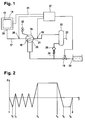
- the pressure P in the chamber 15 is plotted against time T.
- the initial state 1 is in the chamber 15 of the atmospheric pressure of about 1 bar.
- An in Fig. 1 not shown flap is opened and the towels are inserted into the chamber 15.
- the chamber is evacuated to a pressure of about 100 mbar to 120 mbar.
- the germ-containing air is sucked out of the chamber 15.
- a burst of steam with which the chamber 15 is completely filled with steam between the times t1 and t2.
- the pressure in the chamber 15 rises slightly above atmospheric pressure.
- the chamber 15 is evacuated again to 100 mbar to 120 mbar.
- two more bursts of steam with subsequent evacuation.
- the series of bursts of steam serves to reliably and completely rid the chamber 15 of the remnants of the original germ-containing air.
- the chamber 15 is filled once more with steam, this time creating a pressure which is well above atmospheric pressure.
- the absolute pressure at time t3 can be, for example, 3 bar.
- the actual sterilization takes place, which may extend, for example, over 40 minutes. Due to the increased pressure and the steam atmosphere with a temperature of about 140 ° C, germs and pathogens in the towels are rendered harmless.
- a valve is opened so that the vapor can escape from the chamber 15.
- the pressure drops to atmospheric pressure over a period of about 1 minute.
- the chamber is evacuated to a pressure of about 50 mbar.
- the pressure at time t5 is thus significantly lower than the pressure after at time t1.
- the pressure of 50 mbar is maintained for a period of about 20 minutes.
- the moisture in the towels evaporates completely during this period so that the towels are dry at time t6.
- the chamber 15 is then returned to atmospheric pressure, completing the sterilization cycle at time 2.
- the towels can be removed from the chamber 15 and are ready for further use.
- the required for the sterilization cycle negative pressure in the chamber 15 is generated by means of a liquid ring vacuum pump 16 which is connected via a suction passage 17 to the chamber 15.
- the suction tract 17 comprises a Line extending between the chamber 15 and the liquid ring vacuum pump 16 and arranged in front of the working chamber input portion of the vacuum pump 16. At the transition from the chamber 15 to the suction passage 17, an outlet valve 30 is arranged.
- a spray head 18 is arranged, which forms a liquid mouth according to the invention.
- the spray head 18 is connected via a switching valve 19 with a fresh water connection 20.
- the switching valve 19 When the switching valve 19 is opened, water exits in a finely divided form from the spray head 18 and distributed in the suction duct 17.
- the operating fluid forms the liquid ring during operation of the vacuum pump 16 , which seals the impeller against the housing.
- the liquid supplied from the spray head 18 is conveyed to the output side 21 of the vacuum pump 16 together with the medium sucked from the chamber 15.
- a separator 22 the liquid and gaseous components of the pumped medium are separated from each other and the gaseous components are released to the environment. By an overflow 23 excess water is released.
- a return line 24 extends in the direction of the spray head 18 and the inlet 25 for the operating fluid.
- a check valve 26 is arranged in the return line 24.
- the switching valve 19 When the switching valve 19 is opened, the fresh water exits with a pressure that is higher than the pressure in the separator 22.
- the check valve 26 closes, so that the fresh water can flow only in the direction of the vacuum pump 16 and not in the separator 22. If the switching valve 19 is closed, opens the check valve 26 and the liquid from the separator 22 can flow in the direction of the vacuum pump 16. There is then a closed circuit from the vacuum pump 16 via the separator 22 and the return line 24 back to the vacuum pump 16.
- the switching valve 19 is connected to a controller 27 so that the switching valve 19 opens and closes according to control commands from the controller 27.
- the controller 27 receives measurement signals from a pressure sensor 28 and a temperature sensor 29.
- the pressure sensor 28 measures the pressure in the suction tract 17 and is configured to give a control signal when the pressure in the suction tract drops below 100 mbar.
- the temperature sensor 29 measures the temperature of the medium exiting the vacuum pump 16 and is configured to give a control signal when the temperature of the exiting medium exceeds the maximum outlet temperature (e.g., 60 ° C).
- the controller 27 is designed to open the switching valve 19 when it receives a control signal from one of the sensors 28, 29.
- the exhaust valve 30 is opened and the vacuum pump 16 is activated.
- the vacuum pump 16 sucks the air from the chamber 15 and evacuates the chamber 15 to a pressure of about 120 mbar. If the pressure of about 120 mbar is reached, the outlet valve 30 is closed and admitted from a nozzle, not shown, of the autoclave 14 steam in the chamber 15.
- the temperature of the operating fluid can be in This phase, for example, between 50 ° C and 60 ° C lie. As long as the pressure remains above 120 mbar, cavitation in the vacuum pump 16 does not occur despite this temperature of the operating fluid. Excess fluid quantities can still be disposed of via the normal wastewater at this temperature.
- the exhaust valve 30 is opened again and the vacuum pump 16 starts the evacuation process. From the chamber 15 steam is now sucked.
- the steam which can not be simply released into the environment in a hospital, must be condensed. In the arrangement according to the invention, this is done by spraying liquid into the suction tract 17. The vapor comes into contact with the liquid and is cooled so that it condenses almost completely.
- the arrangement according to the invention thus functions as a mixed condenser.
- the vacuum pump 16 starts functioning from the time t2
- the pressure in the suction tract 17 drops below atmospheric pressure within a short time. Due to the negative pressure, water is sucked out of the separator 22, which enters the suction tract 17 via the spray head 18.
- the interaction between the sprayed water and the steam takes place substantially before entering the working space of the vacuum pump 16, which means that the vacuum pump primarily promotes water. This process with the introduction of a steam pulse and subsequent evacuation with condensation of the vapor is repeated twice.
- the pressure in the suction tract 17 is continuously above 100 mbar in this phase, so that the threshold value at which the pressure sensor 28 outputs a control signal does not fall below becomes. As long as the temperature of the water exiting from the vacuum pump 16 remains below 60 ° C, no control signal will come from the temperature sensor 29. The switching valve 19 thus remains closed. The water flows in a closed circuit from the vacuum pump 16 via the separator 22 and the return line 24 back to the vacuum pump, wherein excess water is discharged continuously through the overflow 23. The excess water results primarily from the condensate of the coming out of the chamber 15 steam.
- the condensation of the steam continuously supplies heat to the liquid, so that the temperature of the liquid in the system continuously increases.
- the temperature sensor 29 outputs a control signal and the switching valve 19 of the fresh water connection 20 is opened. It then enters cool water at a temperature of, for example, 20 ° C in the system, while the heated water exits through the overflow 23 from the system.
- the controller 27 is programmed to close the switching valve 19 again when the fluid in the system has been substantially completely replaced once. For example, if the amount of fluid in the system is about 10 liters, the switching valve 19 may be closed again after this volume of fresh water has been supplied. After replacing the water, the closed circuit starts again with the fresh water.
- the outlet valve 30 remains closed and the vacuum pump 16 is inoperative. After completion of the sterilization, the outlet valve 30 is opened at time t4. The pressurized steam exits the chamber 15 so that the pressure within the chamber 15 drops to atmospheric pressure within about 1 minute. Just above atmospheric pressure, the vacuum pump 16 is put into operation, so that the evacuation starts quickly.
- the controller 27 therefore receives a control signal via a line 31 as soon as the outlet valve 30 is opened at the time t4.
- the switching valve 19 is opened, so that fresh water flows in the direction of the spray head 18.
- the pressure of the public water network is generally 4 bar and thus higher than the pressure in the chamber 15. The normal water pressure is thus sufficient to inject the water into the intake tract 17. If the water pressure is insufficient in individual cases, it can be increased by suitable means.
- the sprayed water is pressed together with the condensate through the vacuum pump 16 through, even if the vacuum pump 16 is not in operation.
- the pressure builds up so by itself.
- the switching valve 19 When the vacuum pump is put into operation just above atmospheric pressure, the switching valve 19 is first closed.
- the system is substantially completely filled with fresh water so that the water can be circulated for a time before exceeding the limit of 60 ° C at the outlet of the vacuum pump 16. If the water has heated again to this value, the temperature sensor 29 outputs a control signal and the heated water is exchanged with fresh water.
- the pressure sensor 28 If the chamber 15 is evacuated to 100 mbar, the pressure sensor 28 outputs a control signal.
- the switching valve 19 opens and the system is filled with fresh water. This is to avoid cavitation, which would be expected if at a water temperature in the order of 60 ° C, the pressure would be less than 100 mbar. Air can be admitted into the vacuum pump 16 via a valve 32 in order to further reduce the risk of cavitation.
Description
Die Erfindung betrifft eine Anordnung aus einer Vakuumpumpe und einer Kammer, bei der sich ein Saugtrakt zwischen der Kammer und der Vakuumpumpe erstreckt. Die Vakuumpumpe ist eine Flüssigkeitsringmaschine. Die Erfindung betrifft außerdem ein Verfahren zum Evakuieren einer dampfgefüllten Kammer.The invention relates to an arrangement of a vacuum pump and a chamber in which a suction tract extends between the chamber and the vacuum pump. The vacuum pump is a liquid ring machine. The invention also relates to a method for evacuating a vapor-filled chamber.
Die Druckschrift
Zu den Anwendungen, bei denen eine dampfgefüllte Kammer evakuiert wird, gehören Autoklaven, wie sie etwa in Krankenhäusern zum Sterilisieren von beispielsweise Handtüchern, Bettwäsche oder auch Instrumenten eingesetzt werden. Zum Sterilisieren wird heißer Dampf in die Kammer des Autoklaven eingeleitet. Nach dem Abschluss der Sterilisation wird der Dampf aus der Kammer des Autoklaven abgesaugt, so dass die sterilisierten Gegenstände entnommen werden können. Der Dampf als solcher kann nicht einfach an die Umgebung abgegeben werden. In dem Prozess wird der Dampf deswegen kondensiert, so dass nur noch das Kondensat übrig bleibt.Applications in which a vapor-filled chamber is evacuated include autoclaves, such as those used in hospitals to sterilize, for example, towels, bedding or even instruments. For sterilization hot steam is introduced into the chamber of the autoclave. After completion of the sterilization, the vapor is sucked out of the chamber of the autoclave, so that the sterilized objects can be removed. The steam as such can not simply be released to the environment. In the process, the steam is condensed so that only the condensate remains.
Zum Absaugen des Gases wird eine Vakuumpumpe verwendet, die über einen Saugtrakt an die Kammer des Autoklaven angeschlossen ist. Zum Kondensieren des Dampfs ist bei bisherigen Anordnungen der Saugtrakt mit einem Wärmetauscher ausgestattet, mit dem dem Dampf so viel Wärme entzogen wird, dass er kondensiert. Dass Kondensat wird mit der Vakuumpumpe angesaugt und bei Atmosphärendruck abgegeben.To suck off the gas, a vacuum pump is used, which is connected via a suction tract to the chamber of the autoclave. In order to condense the steam, in previous arrangements the suction tract is equipped with a heat exchanger with which so much heat is extracted from the steam, that he condenses. The condensate is sucked in with the vacuum pump and released at atmospheric pressure.
Als Wärmetauscher in dem Saugtrakt sind beispielsweise Wärmetauscher üblich, bei denen der zu kondensierende Dampf an gekühlten Platten vorbeigeführt wird. Solche Wärmetauscher haben den Nachteil, dass große Mengen Wasser erforderlich sind, um eine niedrige Kondensationstemperatur zu erreichen.As a heat exchanger in the suction tract, for example, heat exchangers are common, in which the vapor to be condensed is passed by cooled plates. Such heat exchangers have the disadvantage that large amounts of water are required to achieve a low condensation temperature.
Der Erfindung liegt die Aufgabe zu Grunde, eine Anordnung und ein Verfahren vorzustellen, mit denen der aus der Kammer angesaugte Dampf auf umweltfreundlichere Weise kondensiert werden kann. Ausgehend vom genannten Stand der Technik wird die Aufgabe gelöst mit den Merkmalen der unabhängigen Ansprüche. Vorteilhafte Ausführungsformen finden sich in den Unteransprüchen.The invention is based on the object to provide an arrangement and a method by which the sucked from the chamber vapor can be condensed in a more environmentally friendly manner. Based on the cited prior art, the object is achieved with the features of the independent claims. Advantageous embodiments can be found in the subclaims.
Erfindungsgemäß ist in dem Saugtrakt eine Flüssigkeitsmündung angeordnet, um aus der Kammer angesaugtes Gas mit Flüssigkeit zu versetzen.According to the invention, a liquid mouth is arranged in the suction tract to displace gas aspirated from the chamber with liquid.
Die Erfindung hat erkannt, dass durch direktes Einbringen von Flüssigkeit in den Saugtrakt der Dampf sehr effektiv kondensiert werden kann. Vergleichsversuche, bei denen einmal ein herkömmlicher Wärmetauscher mit Wasser gekühlt wurde und einmal gemäß der Erfindung direkt Wasser zu dem Gas zugeführt wurde, haben gezeigt, dass der Wasserverbrauch um etwa 50 % vermindert werden konnte.The invention has recognized that by directly introducing liquid into the suction tract, the vapor can be condensed very effectively. Comparative experiments in which once a conventional heat exchanger was cooled with water and once according to the invention directly fed water to the gas, have shown that the water consumption could be reduced by about 50%.
Vakuumpumpen sind dazu ausgelegt, Gas aus einer Kammer anzusaugen, um ein Vakuum in der Kammer zu erzeugen. Das zu fördernde Medium ist bei normaler Verwendung einer Vakuumpumpe also gasförmig. Im Allgemeinen sind Vakuumpumpen empfindlich, wenn sie Flüssigkeitsmengen anstatt eines rein gasförmigen Mediums ansaugen. Der erfindungsgemäße Vorschlag, die Flüssigkeitsmenge in dem Gasstrom durch Zugabe von Flüssigkeit in den Saugtrakt gezielt zu erhöhen, ist insofern unerwartet. Die Erfindung hat jedoch erkannt, dass es mit einer Flüssigkeitsring-Vakuumpumpe möglich ist, die erforderliche Flüssigkeitsmenge zu transportieren, die sich aus dem Kondensat und der zusätzlich eingebrachten Flüssigkeit ergibt. Dabei kann die Eignung der Vakuumpumpe zum Fördern von Flüssigkeit verbessert werden, indem die Einlassöffnung und/oder die Auslassöffnung der Vakuumpumpe einen vergrößerten Querschnitt haben verglichen mit einer Vakuumpumpe, die für die reine Gasförderung optimiert ist. Trotz einer solchen Modifikation bleibt die Saugleistung im Wesentlichen erhalten, so dass die Vakuumpumpe weiterhin in der Lage ist, den gewünschten niedrigen Druck in der Kammer zu erzeugen und aufrechtzuerhalten.Vacuum pumps are designed to draw gas from a chamber to create a vacuum in the chamber. The medium to be delivered is in normal use of a vacuum pump so gaseous. In general, vacuum pumps are sensitive if they suck liquid rather than a pure gaseous medium. The inventive proposal to increase the amount of liquid in the gas stream by adding liquid in the intake targeted, is so far unexpected. The invention has recognized, however, that it is possible with a liquid ring vacuum pump to transport the required amount of liquid resulting from the condensate and the additionally introduced liquid. In this case, the suitability of the vacuum pump for conveying liquid can be improved by the inlet opening and / or the outlet opening of the vacuum pump have an enlarged cross section compared with a vacuum pump, which is optimized for pure gas production. Despite such modification, the suction power is substantially maintained, so that the vacuum pump is further able to generate and maintain the desired low pressure in the chamber.
Ein niedriger Druck in der Kammer ist insbesondere deswegen gewünscht, damit die Gegenstände in der Kammer im Anschluss an die Sterilisation innerhalb kurzer Zeit getrocknet werden können. Bei niedrigem Druck verdampft die Feuchtigkeit und kann dann mit der Vakuumpumpe abgesaugt werden. Das Trocknen geht desto schneller, je niedriger der Druck in der Kammer ist. Die Vakuumpumpe kann dazu ausgelegt sein, in der Kammer ein Vakuum von weniger als 150 mbar, vorzugsweise weniger als 100 mbar, weiter vorzugsweise weniger als 70 mbar zu erzeugen. Eine Evakuierung auf weniger als 30 mbar ist in der Regel nicht erforderlich.A low pressure in the chamber is particularly desirable so that the articles in the chamber can be dried within a short time following sterilization. At low pressure the moisture evaporates and can then be sucked off with the vacuum pump. Drying is faster the lower the pressure in the chamber. The vacuum pump may be configured to generate in the chamber a vacuum of less than 150 mbar, preferably less than 100 mbar, more preferably less than 70 mbar. An evacuation to less than 30 mbar is usually not required.
Für eine wirksame Kondensation des Dampfs ist es von Vorteil, wenn es zu einem großflächigen Kontakt zwischen dem Dampf und der in den Saugtrakt zugeführten Flüssigkeit kommt. Es ist also von Vorteil, wenn die Flüssigkeit in Form kleiner Tropfen zugeführt wird. Die Flüssigkeitsmündung kann deswegen mit einer Sprühöffnung versehen sein. Die Flüssigkeit tritt dann nicht in Form eines konzentrierten Strahls aus, sondern verteilt sich, so dass es zu einer intensiven Wechselwirkung mit dem Dampf kommt.For effective condensation of the vapor, it is advantageous if there is a large-area contact between the Steam and the liquid supplied into the suction tract comes. It is therefore advantageous if the liquid is supplied in the form of small drops. The liquid mouth can therefore be provided with a spray opening. The liquid then does not emerge in the form of a concentrated jet, but spreads, so that it comes to an intense interaction with the vapor.
Die Flüssigkeitsmündung kann in einer Leitung angeordnet sein, die sich zwischen der Kammer und der Vakuumpumpe erstreckt. Möglich ist es auch, dass die Flüssigkeitsmündung in die Vakuumpumpe integriert ist. Die Flüssigkeitsmündung kann im Saugbereich der Vakuumpumpe münden, also beispielsweise im Saugstutzen oder in dem vor der Arbeitskammer angeordneten Saugraum. Die Flüssigkeit wird vorzugsweise zugeführt, bevor der Gasstrom in die Arbeitskammer der Vakuumpumpe eintritt. Der Saugtrakt umfasst den Bereich zwischen der Pumpe und der Kammer, in dem ein Unterdruck besteht, wenn die Vakuumpumpe in Betrieb ist.The liquid mouth may be disposed in a conduit extending between the chamber and the vacuum pump. It is also possible that the liquid mouth is integrated into the vacuum pump. The liquid mouth can open in the suction region of the vacuum pump, that is, for example, in the suction nozzle or in the suction chamber arranged in front of the working chamber. The liquid is preferably supplied before the gas flow enters the working chamber of the vacuum pump. The suction tract comprises the area between the pump and the chamber in which there is a negative pressure when the vacuum pump is in operation.
Die Flüssigkeitsmenge, die sich aus dem Kondensat und der zum Saugtrakt zugeführten Flüssigkeit ergibt, wird durch die Vakuumpumpe hindurch gefördert und tritt auf der Ausgangsseite der Vakuumpumpe wieder aus. Dabei ist nicht ausgeschlossen, dass sich in der Vakuumpumpe die mitgeförderte Flüssigkeit und die Betriebsflüssigkeit, die den Flüssigkeitsring bildet, vermischen und dann eine andere Flüssigkeitsmenge aus der Vakuumpumpe austritt als mit dem Gasstrom die Vakuumpumpe eingetreten ist.The amount of liquid resulting from the condensate and the liquid supplied to the suction tract is conveyed through the vacuum pump and exits again on the output side of the vacuum pump. It is not excluded that in the vacuum pump, the mitgeförderte liquid and the operating fluid, which forms the liquid ring, and then mix a different amount of liquid from the vacuum pump exits than with the gas flow, the vacuum pump has occurred.
An den Ausgang der Vakuumpumpe kann sich ein Abscheider anschließen, in dem mit der Vakuumpumpe geförderte Flüssigkeitsmengen gesammelt werden. Der Abscheider kann mit einem Überlauf ausgestattet sein, durch den überschüssige Flüssigkeit abgegeben wird. Gasmengen, die nach dem Abscheiden der Flüssigkeit übrig bleiben, können an die Umgebung abgegeben werden.At the output of the vacuum pump, a separator can be connected, are collected in the pumped with the vacuum pump liquid quantities. The separator can with a Overflow be provided, is discharged through the excess liquid. Amounts of gas left over after the liquid has been separated can be released to the environment.
Um den Flüssigkeitsverbrauch gering zu halten, kann eine Rückleitung vorgesehen sein, die sich von der Ausgangsseite der Vakuumpumpe bis zu der Flüssigkeitsmündung erstreckt. Es ist dann nicht erforderlich, zum Kondensieren des Dampfs jeweils frische Flüssigkeit zu verwenden, sondern es kann Flüssigkeit verwendet werden, die bereits einmal durch die Vakuumpumpe hindurch gelaufen ist. Der Abscheider gilt als zur Ausgangsseite gehörig. Die Rückleitung kann sich also an den Abscheider anschließen.In order to keep the liquid consumption low, a return line may be provided, which extends from the output side of the vacuum pump to the liquid mouth. It is then not necessary to use each fresh liquid for condensing the steam, but it can be used liquid that has already passed through the vacuum pump once. The separator is considered as belonging to the output side. The return line can therefore connect to the separator.
Die Vakuumpumpe kann außerdem einen Einlass zum Zuführen von Betriebsflüssigkeit aufweisen. Die Betriebsflüssigkeit bildet im Betrieb der Vakuumpumpe den Flüssigkeitsring. In einer vorteilhaften Ausführungsform ist auch der Einlass für die Betriebsflüssigkeit an die Rückleitung angeschlossen, so dass auch die Betriebsflüssigkeit in einem geschlossenen Kreis geführt werden kann.The vacuum pump may further include an inlet for supplying operating fluid. The operating fluid forms the liquid ring during operation of the vacuum pump. In an advantageous embodiment, the inlet for the operating fluid is connected to the return line, so that the operating fluid can be performed in a closed circuit.
Durch die Kondensation des Dampfs wird Wärme übertragen, so dass die Flüssigkeit sich erwärmt. Temperaturen der Flüssigkeit oberhalb einer maximalen Auslasstemperatur, typischerweise 60 °C, sind unerwünscht, weil Flüssigkeiten oberhalb dieser Temperatur nicht mehr einfach mit dem Abwasser entsorgt werden können. Die Anordnung kann deswegen einen Frischwasseranschluss umfassen, so dass dem Saugtrakt und/oder dem Arbeitsraum der Vakuumpumpe bei Bedarf kühlere Flüssigkeit mit beispielsweise Raumtemperatur zugeführt werden kann. Im Gegenzug kann die wärmere Flüssigkeit über den Abscheider abgegeben werden, so dass die Temperatur der im System befindlichen Flüssigkeit insgesamt absinkt.Heat is transferred by the condensation of the steam, so that the liquid heats up. Temperatures of liquid above a maximum outlet temperature, typically 60 ° C, are undesirable because liquids above this temperature can not be easily disposed of with the wastewater. The arrangement can therefore include a fresh water connection, so that the suction tract and / or the working space of the vacuum pump cooler if necessary, for example, room temperature can be supplied. In turn, the warmer fluid can over the separator are discharged, so that the temperature of the liquid in the system drops overall.
Der Frischwasseranschluss kann außerdem genutzt werden, um die Temperatur der Flüssigkeit in dem System abzusenken, wenn der Druck auf der Eingangsseite der Vakuumpumpe niedrig ist. Hat beispielsweise die Betriebsflüssigkeit eine Temperatur von 60 °C, besteht bei Drücken, die unterhalb von etwa unterhalb 100 mbar liegen, das Risiko von Kavitation. Liegt hingegen die Temperatur der Betriebsflüssigkeit bei 20 °C, sind auch Drücke von beispielsweise 50 mbar ohne Kavitation möglich.The fresh water connection can also be used to lower the temperature of the liquid in the system when the pressure on the input side of the vacuum pump is low. For example, if the operating fluid has a temperature of 60 ° C, there is a risk of cavitation at pressures below about 100 mbar. If, however, the temperature of the operating fluid at 20 ° C, pressures of, for example, 50 mbar without cavitation are possible.
Der Frischwasseranschluss kann mit der Rückleitung verbunden sein. Zwischen dem Frischwasseranschluss und der Ausgangsseite der Vakuumpumpe kann ein Rückschlagventil in der Rückleitung angeordnet sein. Aus dem Frischwasseranschluss strömende Flüssigkeit wird dann der Flüssigkeitsmündung und/oder dem Einlass für Betriebsflüssigkeit zugeführt, ohne dass eine vorherige Durchmischung mit der gebrauchten Flüssigkeit stattfindet. Kommt hingegen keine Flüssigkeit aus dem Frischwasseranschluss, öffnet das Rückschlagventil und die Flüssigkeit kann von der Ausgangsseite der Vakuumpumpe über die Rückleitung ungehindert zu der Flüssigkeitsmündung und/oder dem Einlass für die Betriebsflüssigkeit fließen.The fresh water connection can be connected to the return line. Between the fresh water connection and the output side of the vacuum pump, a check valve may be arranged in the return line. Liquid flowing out of the fresh water connection is then supplied to the liquid mouth and / or the operating liquid inlet without prior mixing with the used liquid. If, on the other hand, no liquid comes out of the fresh water connection, the check valve opens and the liquid can flow unhindered from the outlet side of the vacuum pump via the return line to the liquid mouth and / or the inlet for the operating liquid.
In einer vorteilhaften Ausführungsform ist der Frischwasseranschluss mit einem Schaltventil versehen, mit dem der Zustrom von Flüssigkeit aus dem Frischwasseranschluss eingestellt werden kann. Es kann eine Steuerung vorgesehen sein, unter deren Kontrolle das Schaltventil steht. Die Steuerung kann mit einem Temperatursensor für die Temperatur der Flüssigkeit im System verbunden sein. Die Steuerung kann so ausgelegt sein, dass sie das Schaltventil öffnet, wenn die Temperatur einen vorgegebenen Schwellwert überschreitet. Der Schwellwert kann beispielsweise 60 °C betragen, weil nur Flüssigkeit mit einer Temperatur unterhalb dieses Schwellwerts ohne weiteres über das Abwasser abgegeben werden kann.In an advantageous embodiment, the fresh water connection is provided with a switching valve with which the inflow of liquid from the fresh water connection can be adjusted. It can be provided a control, under whose control the switching valve is. The controller can be equipped with a temperature sensor for the temperature be connected to the liquid in the system. The controller may be configured to open the switching valve when the temperature exceeds a predetermined threshold. The threshold value can be, for example, 60 ° C., because only liquid with a temperature below this threshold value can easily be discharged via the wastewater.
Wenn die Flüssigkeit sich über die Rückleitung in einem geschlossenen Kreislauf bewegt, kann der Temperatursensor an einer beliebigen Stelle des Systems angeordnet sein. Die Temperatur kann also beispielsweise innerhalb der Vakuumpumpe, in der Rückleitung, in dem Abscheider oder einem anderen Teil des Flüssigkeitskreislaufs gemessen werden. Wird die Temperatur am Ausgang der Vakuumpumpe oder in dem Abscheider gemessen, hat dies den Vorteil, dass man im Wesentlichen direkt die Temperatur der Flüssigkeit misst, die als Abwasser abgegeben wird.As the liquid moves in a closed loop across the return line, the temperature sensor may be located anywhere in the system. The temperature can thus be measured, for example, within the vacuum pump, in the return line, in the separator or in another part of the liquid circuit. When the temperature at the outlet of the vacuum pump or in the separator is measured, this has the advantage of measuring essentially directly the temperature of the liquid which is discharged as waste water.
Die Steuerung kann außerdem mit einem Drucksensor für den Druck im Saugtrakt verbunden sein und so eingerichtet sein, dass sie das Schaltventil öffnet, wenn der Druck unter einen vorgegebenen Schwellwert absinkt. Der Schwellwert kann zwischen 80 mbar und 200 mbar, vorzugsweise zwischen 100 mbar und 150 mbar liegen. Wenn der Druck unter den Schwellwert absinkt, ist eine niedrigere Temperatur der Flüssigkeit in dem System von Vorteil, weil damit das Risiko von Kavitation abnimmt. Mit dem Öffnen des Schaltventils strömt kühle Flüssigkeit in das System, so dass die Temperatur der Flüssigkeit, insbesondere der Betriebsflüssigkeit absinkt.The controller may also be connected to a pressure sensor for pressure in the intake tract and be arranged to open the switching valve when the pressure falls below a predetermined threshold. The threshold value can be between 80 mbar and 200 mbar, preferably between 100 mbar and 150 mbar. When the pressure drops below the threshold, a lower temperature of the liquid in the system is advantageous because it reduces the risk of cavitation. With the opening of the switching valve cool liquid flows into the system, so that the temperature of the liquid, in particular the operating fluid drops.
Die Steuerung kann weiter so ausgelegt sein, dass sie das Schaltventil wieder schließt, wenn eine vorgegebene Flüssigkeitsmenge aus dem Frischwasseranschluss zugeführt wurde. Die Flüssigkeitsmenge kann beispielsweise so bemessen sein, dass die Flüssigkeit in dem System im Wesentlichen vollständig durch frische Flüssigkeit ersetzt wird. Die vorgegebene Flüssigkeitsmenge kann beispielsweise zwischen 5 l und 15 l liegen.The controller may be further configured to close the switching valve again when a predetermined amount of liquid was supplied from the fresh water connection. For example, the amount of fluid may be such that the fluid in the system is substantially completely replaced with fresh fluid. The predetermined amount of liquid may for example be between 5 l and 15 l.
Gemäß einem weiteren Aspekt kann die Steuerung so ausgelegt sein, dass sie das Schaltventil zu einem Zeitpunkt öffnet, zu dem die Vakuumpumpe nicht in Betrieb ist. Auslöser hierfür kann beispielsweise ein Steuersignal sein, das die Steuerung erhält. Dem Saugtrakt Flüssigkeit zuzuführen, obwohl die Vakuumpumpe nicht in Betrieb ist, kann beispielsweise dann von Interesse sein, wenn der Druck in der Kammer höher ist als Atmosphärendruck und der Dampf deswegen von alleine in Richtung der Vakuumpumpe strömt.In another aspect, the controller may be configured to open the switching valve at a time when the vacuum pump is not operating. The trigger for this, for example, be a control signal, which receives the control. It can be of interest, for example, to supply liquid to the suction tract, although the vacuum pump is not in operation, if the pressure in the chamber is higher than atmospheric pressure and the vapor therefore flows by itself in the direction of the vacuum pump.
Bei der Kammer der erfindungsgemäßen Anordnung kann es sich um die Kammer eines Autoklaven handeln. Die Kammer kann eine verschließbare Öffnung aufweisen, durch die zu sterilisierende Gegenstände in die Kammer eingebracht werden können. Im geschlossenen Zustand ist die Kammer so abgeschlossen, dass sie unter einen Überdruck gesetzt werden kann. Während des Sterilisierens kann der Druck in der Kammer beispielsweise zwischen 2 bar und 4 bar liegen. Alle Druckangaben beziehen sich auf den absoluten Druck.The chamber of the arrangement according to the invention may be the chamber of an autoclave. The chamber can have a closable opening through which objects to be sterilized can be introduced into the chamber. When closed, the chamber is closed so that it can be pressurized. During sterilization, the pressure in the chamber may for example be between 2 bar and 4 bar. All pressure data refer to the absolute pressure.
Bei der Betriebsflüssigkeit und der Flüssigkeit, die durch die Flüssigkeitsmündung zugeführt wird, handelt es sich normalerweise um Wasser. Das Wasser aus dem Frischwasseranschluss kann beispielsweise Raumtemperatur haben und damit kühler sein als das Wasser in dem System, wenn die Vakuumpumpe in Betrieb ist. Ist die Flüssigkeit im System eine andere Flüssigkeit als Wasser, kann auch der Frischwasseranschluss dazu ausgelegt sein, die entsprechende Flüssigkeit zuzuführen.The operating fluid and the liquid supplied through the fluid orifice are usually water. For example, the water from the fresh water connection may be at room temperature and thus cooler than the water in the system when the vacuum pump is operating. Is the fluid in the system a liquid other than water, the fresh water connection can also be designed to supply the corresponding liquid.
Die Erfindung betrifft außerdem ein Verfahren zum Evakuieren einer mit Dampf gefüllten Kammer. Bei dem Verfahren wird eine Vakuumpumpe, die über einen Saugtrakt mit der Kammer verbunden ist, betrieben, um den Dampf aus der Kammer anzusaugen. In dem Saugtrakt wird dem Gasstrom eine Flüssigkeit zugeführt, so dass der Dampf kondensiert.The invention also relates to a method for evacuating a vapor-filled chamber. In the method, a vacuum pump, which is connected via a suction with the chamber, operated to suck the vapor from the chamber. In the suction tract, a liquid is supplied to the gas stream, so that the vapor condenses.
Die Flüssigkeit kann vom Ausgang der Vakuumpumpe zu dem Saugtrakt zurückgeführt werden. In einer vorteilhaften Ausführungsform wird die Flüssigkeit dann zurückgeführt, wenn der Druck in dem Saugtrakt oberhalb eines vorgegebenen Schwellwerts liegt und wenn die Temperatur der Flüssigkeit am Ausgang der Vakuumpumpe unterhalb eines vorgegebenen Schwellwerts liegt. Dem Saugtrakt kann Frischwasser zugeführt wird, wenn der Druck in dem Saugtrakt unter den vorgegebenen Schwellwert sinkt. Dem Saugtrakt kann außerdem Frischwasser zugeführt werden, wenn die Temperatur der Flüssigkeit am Ausgang der Vakuumpumpe den vorgegebenen Schwellwert überschreitet.The liquid can be returned from the outlet of the vacuum pump to the suction tract. In an advantageous embodiment, the liquid is returned when the pressure in the suction tract is above a predetermined threshold and when the temperature of the liquid at the outlet of the vacuum pump is below a predetermined threshold. Fresh water can be supplied to the suction tract when the pressure in the suction tract drops below the predetermined threshold value. Fresh water can also be supplied to the suction tract if the temperature of the liquid at the outlet of the vacuum pump exceeds the predetermined threshold value.
Das Verfahren kann mit weiteren Merkmalen fortgebildet werden, die mit Bezug auf die erfindungsgemäße Anordnung beschrieben sind.The method can be developed with further features which are described with reference to the arrangement according to the invention.
Die Erfindung wird nachfolgend unter Bezugnahme auf die beigefügten Zeichnungen anhand vorteilhafter Ausführungsformen beispielhaft beschrieben. Es zeigen:
- Fig. 1:
- eine schematische Darstellung einer erfindungsgemäßen Anordnung; und
- Fig. 2:
- eine schematische Darstellung eines Sterilisationszyklus.
- Fig. 1:
- a schematic representation of an arrangement according to the invention; and
- Fig. 2:
- a schematic representation of a sterilization cycle.
Eine erfindungsgemäße Anordnung in
Anhand von
Bis zum Zeitpunkt t1 wird die Kammer auf einen Druck von etwa 100 mbar bis 120 mbar evakuiert. Damit wird die keimhaltige Luft aus der Kammer 15 abgesaugt. Es folgt ein Dampfstoß, mit dem die Kammer 15 zwischen den Zeitpunkten t1 und t2 vollständig mit Dampf gefüllt wird. Dabei steigt der Druck in der Kammer 15 leicht über Atmosphärendruck hinaus an. Anschließend wird die Kammer 15 erneut auf 100 mbar bis 120 mbar evakuiert. Es folgen zwei weitere Dampfstöße mit anschließender Evakuierung. Die Folge von Dampfstößen dient dazu, die Kammer 15 zuverlässig und vollständig von den Resten der ursprünglichen keimhaltigen Luft zu befreien.Until time t1, the chamber is evacuated to a pressure of about 100 mbar to 120 mbar. Thus, the germ-containing air is sucked out of the
In der nun folgenden Steigzeit, die sich bis zum Zeitpunkt t3 erstreckt, wird die Kammer 15 ein weiteres Mal mit Dampf gefüllt, wobei dieses Mal ein Druck erzeugt wird, der deutlich oberhalb von Atmosphärendruck liegt. Der absolute Druck zum Zeitpunkt t3 kann beispielsweise 3 bar betragen. Zwischen den Zeitpunkten t3 und t4 findet die eigentliche Sterilisation statt, die sich beispielsweise über 40 min erstrecken kann. Durch den erhöhten Druck und die Dampfatmosphäre mit einer Temperatur von etwa 140 °C werden Keime und Erreger in den Handtüchern unschädlich gemacht.In the following rising time, which extends up to the time t3, the
Zum Zeitpunkt t4 wird ein Ventil geöffnet, so dass der Dampf aus der Kammer 15 entweichen kann. Der Druck sinkt über einen Zeitraum von etwa 1 min bis auf Atmosphärendruck ab. Über einen Zeitraum von etwa einer weiteren Minute wird die Kammer auf einen Druck von etwa 50 mbar evakuiert. Der Druck zum Zeitpunkt t5 ist also deutlich niedriger als der Druck nach zum Zeitpunkt t1.At time t4, a valve is opened so that the vapor can escape from the
Der Druck von 50 mbar wird über einen Zeitraum von etwa 20 min gehalten. Die Feuchtigkeit in den Handtüchern verdampft in diesem Zeitraum vollständig, so dass die Handtücher zum Zeitpunkt t6 trocken sind. Die Kammer 15 wird dann wieder auf Atmosphärendruck gebracht, womit der Sterilisationszyklus zum Zeitpunkt 2 abgeschlossen ist. Die Handtücher können aus der Kammer 15 entnommen werden und sind bereit für eine weitere Verwendung.The pressure of 50 mbar is maintained for a period of about 20 minutes. The moisture in the towels evaporates completely during this period so that the towels are dry at time t6. The
Der für den Sterilisationszyklus erforderliche Unterdruck in der Kammer 15 wird mittels einer Flüssigkeitsring-Vakuumpumpe 16 erzeugt, die über einen Saugtrakt 17 an die Kammer 15 angeschlossen ist. Der Saugtrakt 17 umfasst eine Leitung, die sich zwischen der Kammer 15 und der Flüssigkeitsring-Vakuumpumpe 16 erstreckt, sowie den vor der Arbeitskammer angeordneten Eingangsbereich der Vakuumpumpe 16. Am Übergang von der Kammer 15 zu dem Saugtrakt 17 ist ein Auslassventil 30 angeordnet.The required for the sterilization cycle negative pressure in the
Im Eingangsbereich der Vakuumpumpe 16 ist ein Sprühkopf 18 angeordnet, der eine Flüssigkeitsmündung im Sinne der Erfindung bildet. Der Sprühkopf 18 ist über ein Schaltventil 19 mit einem Frischwasseranschluss 20 verbunden. Wenn das Schaltventil 19 geöffnet ist, tritt Wasser in fein verteilter Form aus dem Sprühkopf 18 aus und verteilt sich im Saugtrakt 17. An dieselbe Zuleitung angeschlossen ist ein Einlass 25 für die Betriebsflüssigkeit der Vakuumpumpe 16. Die Betriebsflüssigkeit bildet im Betrieb der Vakuumpumpe 16 den Flüssigkeitsring, der das Flügelrad gegenüber dem Gehäuse abdichtet.In the inlet region of the
Wenn die Flüssigkeitsring-Vakuumpumpe 16 in Betrieb ist, wird die aus dem Sprühkopf 18 zugeführte Flüssigkeit zusammen mit dem aus der Kammer 15 angesaugten Medium zur Ausgangsseite 21 der Vakuumpumpe 16 gefördert. In einem Abscheider 22 werden die flüssigen und die gasförmigen Bestandteile des geförderten Mediums voneinander getrennt und die gasförmigen Bestandteile werden an die Umgebung abgegeben. Durch einen Überlauf 23 wird überschüssiges Wasser abgegeben.When the liquid
Von dem Abscheider 22 erstreckt sich eine Rückleitung 24 in Richtung des Sprühkopfs 18 und des Einlasses 25 für die Betriebsflüssigkeit. In der Rückleitung 24 ist ein Rückschlagventil 26 angeordnet. Wenn das Schaltventil 19 geöffnet ist, tritt das Frischwasser mit einem Druck aus, der höher ist als der Druck in dem Abscheider 22. Das Rückschlagventil 26 schließt, so dass das Frischwasser nur in Richtung der Vakuumpumpe 16 und nicht in den Abscheider 22 strömen kann. Ist das Schaltventil 19 geschlossen, öffnet das Rückschlagventil 26 und die Flüssigkeit aus dem Abscheider 22 kann in Richtung der Vakuumpumpe 16 strömen. Es gibt dann einen geschlossenen Kreislauf von der Vakuumpumpe 16 über den Abscheider 22 und die Rückleitung 24 zurück zur Vakuumpumpe 16.From the
Das Schaltventil 19 ist mit einer Steuerung 27 verbunden, so dass das Schaltventil 19 gemäß Steuerbefehlen von der Steuerung 27 öffnet bzw. schließt. Die Steuerung 27 empfängt Messsignale von einem Drucksensor 28 und einem Temperatursensor 29. Der Drucksensor 28 misst den Druck in dem Saugtrakt 17 und ist dazu ausgelegt, ein Steuersignal zu geben, wenn der Druck in dem Saugtrakt unter 100 mbar absinkt. Der Temperatursensor 29 misst die Temperatur des aus der Vakuumpumpe 16 austretenden Mediums und ist dazu ausgelegt, ein Steuersignal zu geben, wenn die Temperatur des austretenden Mediums die maximale Auslasstemperatur (z.B. 60 °C) überschreitet. Die Steuerung 27 ist so ausgelegt, dass sie das Schaltventil 19 öffnet, wenn sie von einem der Sensoren 28, 29 ein Steuersignal erhält.The switching
Zu Beginn des Sterilisationszyklus wird zum Zeitpunkt 1 das Auslassventil 30 geöffnet und die Vakuumpumpe 16 in Betrieb gesetzt. Die Vakuumpumpe 16 saugt die Luft aus der Kammer 15 an und evakuiert die Kammer 15 bis auf einen Druck von etwa 120 mbar. Ist der Druck von etwa 120 mbar erreicht, wird das Auslassventil 30 geschlossen und aus einer nicht dargestellten Düse des Autoklaven 14 Dampf in die Kammer 15 eingelassen. Die Temperatur der Betriebsflüssigkeit kann in dieser Phase beispielsweise zwischen 50 °C und 60 °C liegen. Solange der Druck oberhalb von 120 mbar bleibt, kommt es trotz dieser Temperatur der Betriebsflüssigkeit nicht zu Kavitation in der Vakuumpumpe 16. Überschüssige Flüssigkeitsmengen können bei dieser Temperatur noch über das normale Abwasser entsorgt werden.At the beginning of the sterilization cycle, at
Zum Zeitpunkt t2 wird das Auslassventil 30 erneut geöffnet und die Vakuumpumpe 16 beginnt mit dem Evakuierungsprozess. Aus der Kammer 15 wird nun Dampf angesaugt. Der Dampf, der in einem Krankenhaus nicht einfach an die Umgebung abgegeben werden kann, muss kondensiert werden. In der erfindungsgemäßen Anordnung geschieht dies dadurch, dass Flüssigkeit in den Saugtrakt 17 eingesprüht wird. Der Dampf kommt mit der Flüssigkeit in Kontakt und wird so abgekühlt, dass er nahezu vollständig kondensiert. Die erfindungsgemäße Anordnung funktioniert also als Mischkondensator.At time t2, the
Tritt die Vakuumpumpe 16 ausgehend vom Zeitpunkt t2 in Funktion, sinkt der Druck in dem Saugtrakt 17 innerhalb kurzer Zeit unter Atmosphärendruck. Durch den Unterdruck wird Wasser aus dem Abscheider 22 angesaugt, die über den Sprühkopf 18 in den Saugtrakt 17 eintritt. Die Wechselwirkung zwischen dem eingesprühten Wasser und dem Dampf findet im Wesentlichen vor dem Eintritt in den Arbeitsraum der Vakuumpumpe 16 statt, was bedeutet, dass die Vakuumpumpe in erster Linie Wasser fördert. Dieser Vorgang mit Einlassen eines Dampfstoßes und anschließendem Evakuieren unter Kondensation des Dampfs wiederholt sich zweimal.If the
Der Druck im Saugtrakt 17 ist in dieser Phase kontinuierlich oberhalb von 100 mbar, so dass der Schwellwert, bei dem der Drucksensor 28 ein Steuersignal gibt, nicht unterschritten wird. Solange die Temperatur des aus der Vakuumpumpe 16 austretenden Wassers unterhalb von 60 °C bleibt, kommt auch von dem Temperatursensor 29 kein Steuersignal. Das Schaltventil 19 bleibt also geschlossen. Das Wasser fließt in einem geschlossenen Kreislauf von der Vakuumpumpe 16 über den Abscheider 22 und die Rückleitung 24 zurück zur Vakuumpumpe, wobei überschüssiges Wasser kontinuierlich durch den Überlauf 23 abgegeben wird. Das überschüssige Wasser resultiert in erster Linie aus dem Kondensat des aus der Kammer 15 kommenden Dampfs.The pressure in the
Durch die Kondensation des Dampfs wird der Flüssigkeit laufend Wärme zugeführt, so dass sich die Temperatur der Flüssigkeit im System kontinuierlich erhöht. Sobald der Schwellwert von 60 °C überschritten ist, gibt der Temperatursensor 29 ein Steuersignal und das Schaltventil 19 des Frischwasseranschlusses 20 wird geöffnet. Es tritt dann kühles Wasser mit einer Temperatur von beispielsweise 20 °C in das System ein, während das erwärmte Wasser durch den Überlauf 23 aus dem System austritt. Die Steuerung 27 ist so programmiert, dass sie das Schaltventil 19 wieder schließt, wenn die Flüssigkeit in dem System im Wesentlichen einmal vollständig ausgetauscht wurde. Beträgt die Flüssigkeitsmenge in dem System beispielsweise etwa 10 l, kann das Schaltventil 19 wieder geschlossen werden, nachdem dieses Volumen an Frischwasser zugeführt wurde. Nach dem Austausch des Wassers beginnt der geschlossene Kreislauf von neuem mit dem frischen Wasser.The condensation of the steam continuously supplies heat to the liquid, so that the temperature of the liquid in the system continuously increases. As soon as the threshold of 60 ° C is exceeded, the
Während der Steigezeit und während der eigentlichen Sterilisation bleibt das Auslassventil 30 geschlossen und die Vakuumpumpe 16 außer Betrieb. Nach dem Abschluss der Sterilisation wird zum Zeitpunkt t4 das Auslassventil 30 geöffnet. Der unter Überdruck stehende Dampf tritt aus der Kammer 15 aus, so dass der Druck innerhalb der Kammer 15 innerhalb von etwa 1 min auf Atmosphärendruck absinkt. Etwas oberhalb von Atmosphärendruck wird die Vakuumpumpe 16 in Betrieb gesetzt, so dass die Evakuierung zügig einsetzt.During the rise time and during the actual sterilization, the
Bereits bevor die Vakuumpumpe in Gang gesetzt wird, soll der Dampf in dem Saugtrakt 17 kondensieren. Über eine Leitung 31 erhält die Steuerung 27 deswegen ein Steuersignal, sobald das Auslassventil 30 zum Zeitpunkt t4 geöffnet wird. Durch einen Befehl von der Steuerung 27 wird das Schaltventil 19 geöffnet, so dass Frischwasser in Richtung des Sprühkopfs 18 strömt. Der Druck des öffentlichen Wassernetzes liegt im Allgemeinen bei 4 bar und damit höher als der Druck in der Kammer 15. Der normale Wasserdruck reicht also aus, um das Wasser in den Saugtrakt 17 einzuspritzen. Ist der Wasserdruck im Einzelfall nicht ausreichend, kann er mit geeigneten Mitteln erhöht werden.Even before the vacuum pump is started, the steam in the
Solange in der Kammer 15 Überdruck herrscht, wird das eingesprühte Wasser zusammen mit dem Kondensat durch die Vakuumpumpe 16 hindurch gedrückt, auch wenn die Vakuumpumpe 16 nicht in Betrieb ist. Der Überdruck baut sich also von alleine ab.As long as in the
Wenn die Vakuumpumpe knapp oberhalb von Atmosphärendruck in Betrieb gesetzt wird, wird das Schaltventil 19 zunächst geschlossen. Das System ist im Wesentlichen vollständig mit frischem Wasser gefüllt, so dass das Wasser eine Zeit lang im geschlossenen Kreislauf geführt werden kann, bevor die Grenze von 60 °C am Ausgang der Vakuumpumpe 16 überschritten wird. Hat sich das Wasser erneut bis auf diesen Wert erwärmt, gibt der Temperatursensor 29 ein Steuersignal und das erwärmte Wasser wird durch frisches Wasser ausgetauscht.When the vacuum pump is put into operation just above atmospheric pressure, the switching
Ist die Kammer 15 bis auf 100 mbar evakuiert, gibt der Drucksensor 28 ein Steuersignal. Das Schaltventil 19 öffnet und das System wird mit Frischwasser gefüllt. Dies dient der Vermeidung von Kavitation, mit der zu rechnen wäre, wenn bei einer Wassertemperatur in der Größenordnung von 60 °C der Druck kleiner als 100 mbar wäre. Über ein Ventil 32 kann Luft in die Vakuumpumpe 16 eingelassen werden, um das Kavitationsrisiko weiter zu senken.If the
Mit dem frischen Wasser, mit dem das System nun gefüllt ist, erfolgt die weitere Evakuierung bis auf den endgültigen Druck von 50 mbar. In der Trocknungsphase, in der dieser niedrige Druck aufrechterhalten wird, wird jeweils soviel Frischwasser zugeführt, dass das Wasser in dem System etwa bei Raumtemperatur gehalten wird.With the fresh water, with which the system is now filled, the further evacuation takes place up to the final pressure of 50 mbar. In the drying phase, in which this low pressure is maintained, in each case as much fresh water is supplied that the water in the system is kept at about room temperature.
Indem frisches Wasser gezielt nur dann zugeführt wird, wenn es für die Kondensation des Dampfes oder den Betrieb der Pumpe erforderlich ist, wird gegenüber konventionellen Prozessen in erheblichem Umfang Wasser eingespart.By supplying fresh water specifically only when it is necessary for the condensation of the steam or the operation of the pump, water is saved considerably in comparison to conventional processes.
Claims (15)
- An assembly produced from a vacuum pump (16) and a chamber (15), wherein an intake tract (17) extends between the chamber (15) and the vacuum pump (16) and wherein the vacuum pump (16) is a liquid ring machine, characterized in that a liquid outlet (18) is arranged in the intake tract (17) in order to mix gas sucked out of the chamber (15) with liquid.
- The assembly as claimed in claim 1, characterized in that the vacuum pump (16) is designed for the purpose of generating a vacuum of less than 150 mbar, preferably less than 100 mbar, further preferably less than 70 mbar.
- The assembly as claimed in claim 1 or 2, characterized in that the liquid outlet (18) includes a spray opening.
- The assembly as claimed in one of claims 1 to 3, characterized in that a separator (22) connects to the output side (21) of the vacuum pump (16) in order to collect liquid volumes conveyed by the vacuum pump (16).
- The assembly as claimed in one of claims 1 to 4, characterized in that a return line (24), which extends from the outlet side (21) of the vacuum pump (16) as far as the liquid outlet (18), is provided for the liquid.
- The assembly as claimed in claim 5, characterized in that the vacuum pump (16) includes an inlet (25) for supplying an operating liquid and in that the inlet (25) is connected to the return line (24).
- The assembly as claimed in one of claims 1 to 6, characterized by a fresh water connection (20) for supplying a liquid to the liquid outlet (18) and/or to the inlet (25) for the operating liquid.
- The assembly as claimed in claim 7, characterized in that the fresh water connection (20) opens out in the return line (24) and in that a non-return valve (26) is arranged in the return line (24) between the fresh water connection (20) and the outlet side (21) of the vacuum pump (16).
- The assembly as claimed in claim 7 or 8, characterized in that the fresh water connection (20) is provided with a switching valve (19), wherein the switching valve (19) is controlled by a control means (27).
- The assembly as claimed in claim 9, characterized in that the control means (27) is connected to a temperature sensor (29) for the temperature of the liquid and in that the control means (27) is designed for the purpose of opening the switching valve (19) when the temperature exceeds a predefined threshold.
- The assembly as claimed in claim 9 or 10, characterized in that the control means (27) is connected to a pressure sensor (28) for the pressure in the intake tract (17) and in that the control means (27) is designed for the purpose of opening the switching valve (19) when the pressure drops below a predefined threshold.
- A method for evacuating a chamber (15) filled with vapor, by means of which method a vacuum pump (16), which is connected to the chamber (15) by means of an intake tract (17), is operated in order to suck the vapor out of the chamber (15), and by means of which a liquid is supplied to the intake tract (17) such that the vapor condenses.
- The method as claimed in claim 12, characterized in that the liquid is returned to the intake tract (17) from the outlet of the vacuum pump (16) when the pressure in the intake tract (17) is above a predefined threshold (17) and when the temperature of the liquid at the outlet (21) of the vacuum pump (16) is below a predefined threshold.
- The method as claimed in claim 13, characterized in that fresh water is supplied to the intake tract (17) when the pressure in the intake tract (17) drops below a predefined threshold.
- The method as claimed in claim 13 or 14, characterized in that fresh water is supplied to the intake tract (17) when the temperature of the liquid at the outlet (21) of the vacuum pump (16) exceeds the predefined threshold.
Priority Applications (1)
| Application Number | Priority Date | Filing Date | Title |
|---|---|---|---|
| EP14701014.4A EP2946112B1 (en) | 2013-01-21 | 2014-01-16 | Pump arrangement and method for evacuating a vapour-filled chamber |
Applications Claiming Priority (3)
| Application Number | Priority Date | Filing Date | Title |
|---|---|---|---|
| EP13152022 | 2013-01-21 | ||
| EP14701014.4A EP2946112B1 (en) | 2013-01-21 | 2014-01-16 | Pump arrangement and method for evacuating a vapour-filled chamber |
| PCT/EP2014/050807 WO2014111471A1 (en) | 2013-01-21 | 2014-01-16 | Pump assembly and method for evacuating a vapor-filled chamber |
Publications (2)
| Publication Number | Publication Date |
|---|---|
| EP2946112A1 EP2946112A1 (en) | 2015-11-25 |
| EP2946112B1 true EP2946112B1 (en) | 2016-10-05 |
Family
ID=47603394
Family Applications (1)
| Application Number | Title | Priority Date | Filing Date |
|---|---|---|---|
| EP14701014.4A Active EP2946112B1 (en) | 2013-01-21 | 2014-01-16 | Pump arrangement and method for evacuating a vapour-filled chamber |
Country Status (5)
| Country | Link |
|---|---|
| US (1) | US10047747B2 (en) |
| EP (1) | EP2946112B1 (en) |
| CN (1) | CN105026758B (en) |
| IL (1) | IL239742B (en) |
| WO (1) | WO2014111471A1 (en) |
Families Citing this family (9)
| Publication number | Priority date | Publication date | Assignee | Title |
|---|---|---|---|---|
| DK178041B1 (en) * | 2014-06-25 | 2015-04-07 | Hvidtved Larsen As J | Mobile sludge suction as well as method |
| US11512700B2 (en) * | 2015-01-08 | 2022-11-29 | Gardner Denver Nash Llc | Low pressure sealing liquid entry area in a compressor type liquid ring pump |
| GB2571971B (en) * | 2018-03-14 | 2020-09-23 | Edwards Tech Vacuum Engineering Qingdao Co Ltd | Liquid ring pump control |
| GB2571968B (en) * | 2018-03-14 | 2020-09-16 | Edwards Tech Vacuum Engineering (Qingdao) Co Ltd | Liquid ring pump control |
| GB2571970B (en) | 2018-03-14 | 2020-09-16 | Edwards Tech Vacuum Engineering (Qingdao) Co Ltd | A liquid ring pump manifold with integrated non-return valve |
| GB2571969B (en) * | 2018-03-14 | 2020-10-07 | Edwards Tech Vacuum Engineering Qingdao Co Ltd | A liquid ring pump manifold with an integrated spray nozzle |
| JP7213109B2 (en) * | 2019-03-14 | 2023-01-26 | オルガノ株式会社 | Method and apparatus for removing condensate from inflow gas of vacuum pump |
| CN116745529A (en) * | 2020-08-28 | 2023-09-12 | 埃地沃兹真空泵制造(青岛)有限公司 | Control of operating fluid flow into a liquid ring pump |
| FR3129991B1 (en) * | 2021-12-08 | 2024-04-19 | Pfeiffer Vacuum | Vacuum line, pumping device intended to be connected to the vacuum line and installation comprising the vacuum line |
Family Cites Families (11)
| Publication number | Priority date | Publication date | Assignee | Title |
|---|---|---|---|---|
| US3642384A (en) * | 1969-11-19 | 1972-02-15 | Henry Huse | Multistage vacuum pumping system |
| US4385868A (en) * | 1979-11-19 | 1983-05-31 | Nash Engineering Company | Systems for evacuating process fluids having condensable and incondensable components |
| US4315717A (en) * | 1979-11-19 | 1982-02-16 | The Nash Engineering Company | Evacuation system with precondenser |
| US4914921A (en) * | 1988-08-16 | 1990-04-10 | Cbi Research Corporation | Refrigeration method and apparatus using aqueous liquid sealed compressor |
| DE19739144C2 (en) * | 1997-09-06 | 2002-04-18 | Geesthacht Gkss Forschung | Device for removing water vapor from pressurized gases or gas mixtures |
| JP2000199490A (en) * | 1998-11-02 | 2000-07-18 | Chiyoda Manufacturing Co Ltd | Device and method for steam sterilization and water sealing type vacuum pump |
| FR2822200B1 (en) * | 2001-03-19 | 2003-09-26 | Cit Alcatel | PUMPING SYSTEM FOR LOW THERMAL CONDUCTIVITY GASES |
| DE10214331A1 (en) | 2002-03-28 | 2003-10-23 | Nash Elmo Ind Gmbh | Pump device, method for operating a pump device and its use in a steam turbine system |
| EP2060275B1 (en) * | 2007-11-13 | 2010-05-12 | CISA S.p.A. | Steam sterilizing system |
| CN101757648A (en) * | 2008-12-09 | 2010-06-30 | 张家港市神农药机有限公司 | Evacuating device of steam sterilization cabinet |
| US8657584B2 (en) | 2010-02-16 | 2014-02-25 | Edwards Limited | Apparatus and method for tuning pump speed |
-
2014
- 2014-01-16 CN CN201480005247.0A patent/CN105026758B/en active Active
- 2014-01-16 EP EP14701014.4A patent/EP2946112B1/en active Active
- 2014-01-16 WO PCT/EP2014/050807 patent/WO2014111471A1/en active Application Filing
- 2014-01-16 US US14/762,005 patent/US10047747B2/en active Active
-
2015
- 2015-07-01 IL IL239742A patent/IL239742B/en active IP Right Grant
Also Published As
| Publication number | Publication date |
|---|---|
| EP2946112A1 (en) | 2015-11-25 |
| CN105026758A (en) | 2015-11-04 |
| US20150361979A1 (en) | 2015-12-17 |
| IL239742A0 (en) | 2015-08-31 |
| US10047747B2 (en) | 2018-08-14 |
| WO2014111471A1 (en) | 2014-07-24 |
| IL239742B (en) | 2019-05-30 |
| CN105026758B (en) | 2017-08-01 |
Similar Documents
| Publication | Publication Date | Title |
|---|---|---|
| EP2946112B1 (en) | Pump arrangement and method for evacuating a vapour-filled chamber | |
| DE60038547T2 (en) | steam heater | |
| DE69836683T2 (en) | autoclave | |
| DE60203603T2 (en) | HIGH-FLASH EVAPORATOR | |
| DE69732442T2 (en) | Continuous closed loop decontamination system and method | |
| EP2928514B1 (en) | Aspirating device having a flushable drainage line | |
| DE3625468A1 (en) | STERILIZATION DEVICE | |
| WO2019025087A1 (en) | Device and method for producing a particle foam part | |
| DE112018000387B4 (en) | Vacuum drying device and vacuum drying method | |
| EP1000244B2 (en) | Method for evacuating a wet gas, treatment device for carrying out this method and suction pump for a treatment device of this type | |
| DE2020303C3 (en) | Device for sterilizing a system for the thermal treatment of liquid products | |
| DE102006026107B3 (en) | Device for disinfecting a reverse osmosis system | |
| EP2832241B1 (en) | Device and method for condensing steam in a vacuum chamber | |
| EP2952702A1 (en) | Method for heating or maintaining the temperature of a steam turbine | |
| DE1492272C3 (en) | ||
| WO2018122154A1 (en) | Hydraulic arrangement and method for drying a hydraulic pressure medium | |
| DE10214331A1 (en) | Pump device, method for operating a pump device and its use in a steam turbine system | |
| DE3522890C2 (en) | Device and method for generating sterile air | |
| DE102013007132A1 (en) | Device for degassing liquids e.g. water, has generating unit which is provided for generating negative pressure in cavity arranged with pump or vacuum vessel, and limiting unit is provided for limiting expansion of container | |
| DE2921915A1 (en) | Sterilisation of sensitive porous articles - by vacuum and pressure application prior to active agent admission | |
| DE102012010739A1 (en) | Condenser for steam sterilizer, has condensate outlet and gas outlet that are provided at lower end wall, and are connected with suction pump through respective valves | |
| EP2308576B1 (en) | Vaporiser | |
| EP3653288B1 (en) | Steam sterilisation device and method for its operation | |
| EP2635358A1 (en) | Microwave-based method and device for producing high-purity liquids | |
| DE102015218427B3 (en) | Apparatus and method for cooling a process fluid of an autoclave |
Legal Events
| Date | Code | Title | Description |
|---|---|---|---|
| PUAI | Public reference made under article 153(3) epc to a published international application that has entered the european phase |
Free format text: ORIGINAL CODE: 0009012 |
|
| 17P | Request for examination filed |
Effective date: 20150610 |
|
| AK | Designated contracting states |
Kind code of ref document: A1 Designated state(s): AL AT BE BG CH CY CZ DE DK EE ES FI FR GB GR HR HU IE IS IT LI LT LU LV MC MK MT NL NO PL PT RO RS SE SI SK SM TR |
|
| AX | Request for extension of the european patent |
Extension state: BA ME |
|
| DAX | Request for extension of the european patent (deleted) | ||
| GRAP | Despatch of communication of intention to grant a patent |
Free format text: ORIGINAL CODE: EPIDOSNIGR1 |
|
| INTG | Intention to grant announced |
Effective date: 20160511 |
|
| GRAS | Grant fee paid |
Free format text: ORIGINAL CODE: EPIDOSNIGR3 |
|
| GRAA | (expected) grant |
Free format text: ORIGINAL CODE: 0009210 |
|
| AK | Designated contracting states |
Kind code of ref document: B1 Designated state(s): AL AT BE BG CH CY CZ DE DK EE ES FI FR GB GR HR HU IE IS IT LI LT LU LV MC MK MT NL NO PL PT RO RS SE SI SK SM TR |
|
| REG | Reference to a national code |
Ref country code: GB Ref legal event code: FG4D Free format text: NOT ENGLISH |
|
| REG | Reference to a national code |
Ref country code: CH Ref legal event code: EP |
|
| REG | Reference to a national code |
Ref country code: AT Ref legal event code: REF Ref document number: 834919 Country of ref document: AT Kind code of ref document: T Effective date: 20161015 |
|
| REG | Reference to a national code |
Ref country code: IE Ref legal event code: FG4D Free format text: LANGUAGE OF EP DOCUMENT: GERMAN |
|
| REG | Reference to a national code |
Ref country code: DE Ref legal event code: R096 Ref document number: 502014001647 Country of ref document: DE |
|
| REG | Reference to a national code |
Ref country code: SE Ref legal event code: TRGR |
|
| REG | Reference to a national code |
Ref country code: NL Ref legal event code: MP Effective date: 20161005 |
|
| REG | Reference to a national code |
Ref country code: LT Ref legal event code: MG4D |
|
| PG25 | Lapsed in a contracting state [announced via postgrant information from national office to epo] |
Ref country code: LV Free format text: LAPSE BECAUSE OF FAILURE TO SUBMIT A TRANSLATION OF THE DESCRIPTION OR TO PAY THE FEE WITHIN THE PRESCRIBED TIME-LIMIT Effective date: 20161005 |
|
| REG | Reference to a national code |
Ref country code: FR Ref legal event code: PLFP Year of fee payment: 4 |
|
| PG25 | Lapsed in a contracting state [announced via postgrant information from national office to epo] |
Ref country code: LT Free format text: LAPSE BECAUSE OF FAILURE TO SUBMIT A TRANSLATION OF THE DESCRIPTION OR TO PAY THE FEE WITHIN THE PRESCRIBED TIME-LIMIT Effective date: 20161005 Ref country code: NO Free format text: LAPSE BECAUSE OF FAILURE TO SUBMIT A TRANSLATION OF THE DESCRIPTION OR TO PAY THE FEE WITHIN THE PRESCRIBED TIME-LIMIT Effective date: 20170105 Ref country code: GR Free format text: LAPSE BECAUSE OF FAILURE TO SUBMIT A TRANSLATION OF THE DESCRIPTION OR TO PAY THE FEE WITHIN THE PRESCRIBED TIME-LIMIT Effective date: 20170106 |
|
| PG25 | Lapsed in a contracting state [announced via postgrant information from national office to epo] |
Ref country code: HR Free format text: LAPSE BECAUSE OF FAILURE TO SUBMIT A TRANSLATION OF THE DESCRIPTION OR TO PAY THE FEE WITHIN THE PRESCRIBED TIME-LIMIT Effective date: 20161005 Ref country code: BE Free format text: LAPSE BECAUSE OF NON-PAYMENT OF DUE FEES Effective date: 20170131 Ref country code: PL Free format text: LAPSE BECAUSE OF FAILURE TO SUBMIT A TRANSLATION OF THE DESCRIPTION OR TO PAY THE FEE WITHIN THE PRESCRIBED TIME-LIMIT Effective date: 20161005 Ref country code: IS Free format text: LAPSE BECAUSE OF FAILURE TO SUBMIT A TRANSLATION OF THE DESCRIPTION OR TO PAY THE FEE WITHIN THE PRESCRIBED TIME-LIMIT Effective date: 20170205 Ref country code: ES Free format text: LAPSE BECAUSE OF FAILURE TO SUBMIT A TRANSLATION OF THE DESCRIPTION OR TO PAY THE FEE WITHIN THE PRESCRIBED TIME-LIMIT Effective date: 20161005 Ref country code: NL Free format text: LAPSE BECAUSE OF FAILURE TO SUBMIT A TRANSLATION OF THE DESCRIPTION OR TO PAY THE FEE WITHIN THE PRESCRIBED TIME-LIMIT Effective date: 20161005 Ref country code: PT Free format text: LAPSE BECAUSE OF FAILURE TO SUBMIT A TRANSLATION OF THE DESCRIPTION OR TO PAY THE FEE WITHIN THE PRESCRIBED TIME-LIMIT Effective date: 20170206 Ref country code: FI Free format text: LAPSE BECAUSE OF FAILURE TO SUBMIT A TRANSLATION OF THE DESCRIPTION OR TO PAY THE FEE WITHIN THE PRESCRIBED TIME-LIMIT Effective date: 20161005 Ref country code: RS Free format text: LAPSE BECAUSE OF FAILURE TO SUBMIT A TRANSLATION OF THE DESCRIPTION OR TO PAY THE FEE WITHIN THE PRESCRIBED TIME-LIMIT Effective date: 20161005 |
|
| REG | Reference to a national code |
Ref country code: DE Ref legal event code: R097 Ref document number: 502014001647 Country of ref document: DE |
|
| PG25 | Lapsed in a contracting state [announced via postgrant information from national office to epo] |
Ref country code: RO Free format text: LAPSE BECAUSE OF FAILURE TO SUBMIT A TRANSLATION OF THE DESCRIPTION OR TO PAY THE FEE WITHIN THE PRESCRIBED TIME-LIMIT Effective date: 20161005 Ref country code: SK Free format text: LAPSE BECAUSE OF FAILURE TO SUBMIT A TRANSLATION OF THE DESCRIPTION OR TO PAY THE FEE WITHIN THE PRESCRIBED TIME-LIMIT Effective date: 20161005 Ref country code: CZ Free format text: LAPSE BECAUSE OF FAILURE TO SUBMIT A TRANSLATION OF THE DESCRIPTION OR TO PAY THE FEE WITHIN THE PRESCRIBED TIME-LIMIT Effective date: 20161005 Ref country code: EE Free format text: LAPSE BECAUSE OF FAILURE TO SUBMIT A TRANSLATION OF THE DESCRIPTION OR TO PAY THE FEE WITHIN THE PRESCRIBED TIME-LIMIT Effective date: 20161005 Ref country code: DK Free format text: LAPSE BECAUSE OF FAILURE TO SUBMIT A TRANSLATION OF THE DESCRIPTION OR TO PAY THE FEE WITHIN THE PRESCRIBED TIME-LIMIT Effective date: 20161005 |
|
| PLBE | No opposition filed within time limit |
Free format text: ORIGINAL CODE: 0009261 |
|
| STAA | Information on the status of an ep patent application or granted ep patent |
Free format text: STATUS: NO OPPOSITION FILED WITHIN TIME LIMIT |
|
| PG25 | Lapsed in a contracting state [announced via postgrant information from national office to epo] |
Ref country code: SM Free format text: LAPSE BECAUSE OF FAILURE TO SUBMIT A TRANSLATION OF THE DESCRIPTION OR TO PAY THE FEE WITHIN THE PRESCRIBED TIME-LIMIT Effective date: 20161005 Ref country code: BG Free format text: LAPSE BECAUSE OF FAILURE TO SUBMIT A TRANSLATION OF THE DESCRIPTION OR TO PAY THE FEE WITHIN THE PRESCRIBED TIME-LIMIT Effective date: 20170105 |
|
| REG | Reference to a national code |
Ref country code: CH Ref legal event code: PL |
|
| 26N | No opposition filed |
Effective date: 20170706 |
|
| PG25 | Lapsed in a contracting state [announced via postgrant information from national office to epo] |
Ref country code: MC Free format text: LAPSE BECAUSE OF FAILURE TO SUBMIT A TRANSLATION OF THE DESCRIPTION OR TO PAY THE FEE WITHIN THE PRESCRIBED TIME-LIMIT Effective date: 20161005 |
|
| PG25 | Lapsed in a contracting state [announced via postgrant information from national office to epo] |
Ref country code: CH Free format text: LAPSE BECAUSE OF NON-PAYMENT OF DUE FEES Effective date: 20170131 Ref country code: LI Free format text: LAPSE BECAUSE OF NON-PAYMENT OF DUE FEES Effective date: 20170131 |
|
| REG | Reference to a national code |
Ref country code: IE Ref legal event code: MM4A |
|
| PG25 | Lapsed in a contracting state [announced via postgrant information from national office to epo] |
Ref country code: SI Free format text: LAPSE BECAUSE OF FAILURE TO SUBMIT A TRANSLATION OF THE DESCRIPTION OR TO PAY THE FEE WITHIN THE PRESCRIBED TIME-LIMIT Effective date: 20161005 Ref country code: LU Free format text: LAPSE BECAUSE OF NON-PAYMENT OF DUE FEES Effective date: 20170116 |
|
| REG | Reference to a national code |
Ref country code: FR Ref legal event code: PLFP Year of fee payment: 5 |
|
| REG | Reference to a national code |
Ref country code: BE Ref legal event code: MM Effective date: 20170131 |
|
| PG25 | Lapsed in a contracting state [announced via postgrant information from national office to epo] |
Ref country code: IE Free format text: LAPSE BECAUSE OF NON-PAYMENT OF DUE FEES Effective date: 20170116 |
|
| PG25 | Lapsed in a contracting state [announced via postgrant information from national office to epo] |
Ref country code: MT Free format text: LAPSE BECAUSE OF FAILURE TO SUBMIT A TRANSLATION OF THE DESCRIPTION OR TO PAY THE FEE WITHIN THE PRESCRIBED TIME-LIMIT Effective date: 20161005 |
|
| PG25 | Lapsed in a contracting state [announced via postgrant information from national office to epo] |
Ref country code: HU Free format text: LAPSE BECAUSE OF FAILURE TO SUBMIT A TRANSLATION OF THE DESCRIPTION OR TO PAY THE FEE WITHIN THE PRESCRIBED TIME-LIMIT; INVALID AB INITIO Effective date: 20140116 |
|
| PG25 | Lapsed in a contracting state [announced via postgrant information from national office to epo] |
Ref country code: CY Free format text: LAPSE BECAUSE OF FAILURE TO SUBMIT A TRANSLATION OF THE DESCRIPTION OR TO PAY THE FEE WITHIN THE PRESCRIBED TIME-LIMIT Effective date: 20161005 |
|
| PG25 | Lapsed in a contracting state [announced via postgrant information from national office to epo] |
Ref country code: MK Free format text: LAPSE BECAUSE OF FAILURE TO SUBMIT A TRANSLATION OF THE DESCRIPTION OR TO PAY THE FEE WITHIN THE PRESCRIBED TIME-LIMIT Effective date: 20161005 |
|
| PG25 | Lapsed in a contracting state [announced via postgrant information from national office to epo] |
Ref country code: TR Free format text: LAPSE BECAUSE OF FAILURE TO SUBMIT A TRANSLATION OF THE DESCRIPTION OR TO PAY THE FEE WITHIN THE PRESCRIBED TIME-LIMIT Effective date: 20161005 |
|
| PG25 | Lapsed in a contracting state [announced via postgrant information from national office to epo] |
Ref country code: AL Free format text: LAPSE BECAUSE OF FAILURE TO SUBMIT A TRANSLATION OF THE DESCRIPTION OR TO PAY THE FEE WITHIN THE PRESCRIBED TIME-LIMIT Effective date: 20161005 |
|
| PGFP | Annual fee paid to national office [announced via postgrant information from national office to epo] |
Ref country code: FR Payment date: 20230125 Year of fee payment: 10 Ref country code: AT Payment date: 20230103 Year of fee payment: 10 |
|
| PGFP | Annual fee paid to national office [announced via postgrant information from national office to epo] |
Ref country code: SE Payment date: 20230127 Year of fee payment: 10 Ref country code: IT Payment date: 20230120 Year of fee payment: 10 Ref country code: GB Payment date: 20230127 Year of fee payment: 10 Ref country code: DE Payment date: 20230127 Year of fee payment: 10 |
|
| PGFP | Annual fee paid to national office [announced via postgrant information from national office to epo] |
Ref country code: AT Payment date: 20240104 Year of fee payment: 11 |