EP2832241B1 - Device and method for condensing steam in a vacuum chamber - Google Patents
Device and method for condensing steam in a vacuum chamber Download PDFInfo
- Publication number
- EP2832241B1 EP2832241B1 EP14179208.5A EP14179208A EP2832241B1 EP 2832241 B1 EP2832241 B1 EP 2832241B1 EP 14179208 A EP14179208 A EP 14179208A EP 2832241 B1 EP2832241 B1 EP 2832241B1
- Authority
- EP
- European Patent Office
- Prior art keywords
- vacuum
- vapor
- chamber
- steam
- coolant
- Prior art date
- Legal status (The legal status is an assumption and is not a legal conclusion. Google has not performed a legal analysis and makes no representation as to the accuracy of the status listed.)
- Active
Links
- 238000000034 method Methods 0.000 title claims description 46
- 239000002826 coolant Substances 0.000 claims description 174
- 238000001816 cooling Methods 0.000 claims description 92
- XLYOFNOQVPJJNP-UHFFFAOYSA-N water Substances O XLYOFNOQVPJJNP-UHFFFAOYSA-N 0.000 claims description 81
- 230000008569 process Effects 0.000 claims description 32
- 238000000926 separation method Methods 0.000 claims description 32
- 235000015173 baked goods and baking mixes Nutrition 0.000 claims description 18
- 239000000356 contaminant Substances 0.000 claims description 12
- 238000009833 condensation Methods 0.000 claims description 10
- 230000005494 condensation Effects 0.000 claims description 10
- 238000011144 upstream manufacturing Methods 0.000 claims description 5
- 238000011049 filling Methods 0.000 claims description 2
- 239000013505 freshwater Substances 0.000 claims description 2
- 238000000605 extraction Methods 0.000 claims 1
- 235000013305 food Nutrition 0.000 description 43
- 239000007788 liquid Substances 0.000 description 19
- 238000009423 ventilation Methods 0.000 description 12
- 239000012535 impurity Substances 0.000 description 11
- 239000012530 fluid Substances 0.000 description 9
- 238000011084 recovery Methods 0.000 description 9
- 230000001105 regulatory effect Effects 0.000 description 8
- 238000012546 transfer Methods 0.000 description 7
- 238000009835 boiling Methods 0.000 description 6
- 239000007921 spray Substances 0.000 description 6
- 239000004744 fabric Substances 0.000 description 5
- 239000010687 lubricating oil Substances 0.000 description 5
- 239000003921 oil Substances 0.000 description 5
- 230000002378 acidificating effect Effects 0.000 description 4
- 230000033228 biological regulation Effects 0.000 description 4
- 235000008429 bread Nutrition 0.000 description 4
- 230000008859 change Effects 0.000 description 4
- 239000000839 emulsion Substances 0.000 description 4
- 239000000203 mixture Substances 0.000 description 4
- 238000012545 processing Methods 0.000 description 4
- 238000004140 cleaning Methods 0.000 description 3
- 230000007423 decrease Effects 0.000 description 3
- 238000001035 drying Methods 0.000 description 3
- 230000000694 effects Effects 0.000 description 3
- 238000005265 energy consumption Methods 0.000 description 3
- 238000004519 manufacturing process Methods 0.000 description 3
- 239000002184 metal Substances 0.000 description 3
- 239000002245 particle Substances 0.000 description 3
- 239000002904 solvent Substances 0.000 description 3
- 230000015572 biosynthetic process Effects 0.000 description 2
- 230000001419 dependent effect Effects 0.000 description 2
- 238000010438 heat treatment Methods 0.000 description 2
- 238000011068 loading method Methods 0.000 description 2
- 230000014759 maintenance of location Effects 0.000 description 2
- 239000010865 sewage Substances 0.000 description 2
- 229910001220 stainless steel Inorganic materials 0.000 description 2
- 239000010935 stainless steel Substances 0.000 description 2
- 239000002351 wastewater Substances 0.000 description 2
- 229910000831 Steel Inorganic materials 0.000 description 1
- 230000002745 absorbent Effects 0.000 description 1
- 239000002250 absorbent Substances 0.000 description 1
- 239000000654 additive Substances 0.000 description 1
- 238000009529 body temperature measurement Methods 0.000 description 1
- 239000003990 capacitor Substances 0.000 description 1
- 238000011109 contamination Methods 0.000 description 1
- 230000007797 corrosion Effects 0.000 description 1
- 238000005260 corrosion Methods 0.000 description 1
- 230000006735 deficit Effects 0.000 description 1
- 238000006073 displacement reaction Methods 0.000 description 1
- 238000009826 distribution Methods 0.000 description 1
- 239000003925 fat Substances 0.000 description 1
- 235000013312 flour Nutrition 0.000 description 1
- 239000013529 heat transfer fluid Substances 0.000 description 1
- 230000006872 improvement Effects 0.000 description 1
- 238000012423 maintenance Methods 0.000 description 1
- 238000005259 measurement Methods 0.000 description 1
- 239000003595 mist Substances 0.000 description 1
- 239000011148 porous material Substances 0.000 description 1
- 238000002360 preparation method Methods 0.000 description 1
- 238000004321 preservation Methods 0.000 description 1
- 238000003672 processing method Methods 0.000 description 1
- 230000009467 reduction Effects 0.000 description 1
- 239000010959 steel Substances 0.000 description 1
- 230000001954 sterilising effect Effects 0.000 description 1
- 238000004659 sterilization and disinfection Methods 0.000 description 1
- 239000002759 woven fabric Substances 0.000 description 1
Images


Classifications
-
- A—HUMAN NECESSITIES
- A21—BAKING; EDIBLE DOUGHS
- A21D—TREATMENT, e.g. PRESERVATION, OF FLOUR OR DOUGH, e.g. BY ADDITION OF MATERIALS; BAKING; BAKERY PRODUCTS; PRESERVATION THEREOF
- A21D15/00—Preserving finished, partly finished or par-baked bakery products; Improving
- A21D15/02—Preserving finished, partly finished or par-baked bakery products; Improving by cooling, e.g. refrigeration, freezing
-
- A—HUMAN NECESSITIES
- A23—FOODS OR FOODSTUFFS; TREATMENT THEREOF, NOT COVERED BY OTHER CLASSES
- A23L—FOODS, FOODSTUFFS, OR NON-ALCOHOLIC BEVERAGES, NOT COVERED BY SUBCLASSES A21D OR A23B-A23J; THEIR PREPARATION OR TREATMENT, e.g. COOKING, MODIFICATION OF NUTRITIVE QUALITIES, PHYSICAL TREATMENT; PRESERVATION OF FOODS OR FOODSTUFFS, IN GENERAL
- A23L3/00—Preservation of foods or foodstuffs, in general, e.g. pasteurising, sterilising, specially adapted for foods or foodstuffs
- A23L3/34—Preservation of foods or foodstuffs, in general, e.g. pasteurising, sterilising, specially adapted for foods or foodstuffs by treatment with chemicals
- A23L3/3409—Preservation of foods or foodstuffs, in general, e.g. pasteurising, sterilising, specially adapted for foods or foodstuffs by treatment with chemicals in the form of gases, e.g. fumigation; Compositions or apparatus therefor
- A23L3/3418—Preservation of foods or foodstuffs, in general, e.g. pasteurising, sterilising, specially adapted for foods or foodstuffs by treatment with chemicals in the form of gases, e.g. fumigation; Compositions or apparatus therefor in a controlled atmosphere, e.g. partial vacuum, comprising only CO2, N2, O2 or H2O
-
- A—HUMAN NECESSITIES
- A23—FOODS OR FOODSTUFFS; TREATMENT THEREOF, NOT COVERED BY OTHER CLASSES
- A23L—FOODS, FOODSTUFFS, OR NON-ALCOHOLIC BEVERAGES, NOT COVERED BY SUBCLASSES A21D OR A23B-A23J; THEIR PREPARATION OR TREATMENT, e.g. COOKING, MODIFICATION OF NUTRITIVE QUALITIES, PHYSICAL TREATMENT; PRESERVATION OF FOODS OR FOODSTUFFS, IN GENERAL
- A23L3/00—Preservation of foods or foodstuffs, in general, e.g. pasteurising, sterilising, specially adapted for foods or foodstuffs
- A23L3/36—Freezing; Subsequent thawing; Cooling
- A23L3/363—Freezing; Subsequent thawing; Cooling the materials not being transported through or in the apparatus with or without shaping, e.g. in form of powder, granules, or flakes
- A23L3/364—Freezing; Subsequent thawing; Cooling the materials not being transported through or in the apparatus with or without shaping, e.g. in form of powder, granules, or flakes with packages or with shaping in form of blocks or portions
-
- B—PERFORMING OPERATIONS; TRANSPORTING
- B01—PHYSICAL OR CHEMICAL PROCESSES OR APPARATUS IN GENERAL
- B01D—SEPARATION
- B01D5/00—Condensation of vapours; Recovering volatile solvents by condensation
- B01D5/0033—Other features
- B01D5/0045—Vacuum condensation
-
- F—MECHANICAL ENGINEERING; LIGHTING; HEATING; WEAPONS; BLASTING
- F25—REFRIGERATION OR COOLING; COMBINED HEATING AND REFRIGERATION SYSTEMS; HEAT PUMP SYSTEMS; MANUFACTURE OR STORAGE OF ICE; LIQUEFACTION SOLIDIFICATION OF GASES
- F25D—REFRIGERATORS; COLD ROOMS; ICE-BOXES; COOLING OR FREEZING APPARATUS NOT OTHERWISE PROVIDED FOR
- F25D31/00—Other cooling or freezing apparatus
-
- F—MECHANICAL ENGINEERING; LIGHTING; HEATING; WEAPONS; BLASTING
- F28—HEAT EXCHANGE IN GENERAL
- F28B—STEAM OR VAPOUR CONDENSERS
- F28B3/00—Condensers in which the steam or vapour comes into direct contact with the cooling medium
- F28B3/06—Condensers in which the steam or vapour comes into direct contact with the cooling medium by injecting the steam or vapour into the cooling liquid
-
- F—MECHANICAL ENGINEERING; LIGHTING; HEATING; WEAPONS; BLASTING
- F28—HEAT EXCHANGE IN GENERAL
- F28B—STEAM OR VAPOUR CONDENSERS
- F28B9/00—Auxiliary systems, arrangements, or devices
- F28B9/02—Auxiliary systems, arrangements, or devices for feeding steam or vapour to condensers
Definitions
- the invention relates to a vacuum cooling device for food, in particular baked goods, which is suitable for the condensation of a vapor, in particular water vapor.
- a vacuum cooling system for cooling food, in particular baked goods, for example freshly baked bread under a negative pressure comprises a vacuum chamber which is designed to hold the fresh food for cooling it; a vacuum source, such as a vacuum pump, connected to the vacuum chamber for ejecting steam from the vacuum chamber and creating a vacuum in the vacuum chamber, and a steam condenser.
- Such a device contains a tube coil or tube bundle arranged in a water container, in which the vapors to be condensed circulate.
- the coil is fed into a receptacle, which is used to hold the condensate. If the vapors in the coil are not fully condensed by the water bath, the vapors collecting in the receptacle can be condensed in an auxiliary condenser.
- This auxiliary condenser is also arranged in the water container within a displacement body.
- the auxiliary capacitor may contain an absorbent through which the moisture is absorbed.
- a condenser for high pressure steam is off for steam engines WO97 / 32113 known, which consists of a pressure vessel in which steam is introduced via a steam supply line. The steam is fed directly into a water bath via a distributor.
- the distributor has a plurality of Distribution pipes that protrude into the water bath.
- the manifolds are in direct contact with the water bath through a plurality of small openings, so that steam in the form of bubbles is introduced through the openings into the water bath, where it condenses.
- Hot and moist foods can be cooled very efficiently by evacuation in a vacuum chamber, which means that only a short cooling time is required.
- very large volumes of steam are generated during the evacuation process, which can be a multiple of the chamber volume.
- the steam volume can be, for example, up to 100 times the chamber volume.
- the performance of the vacuum pump is determined by the volume of steam. This means that the vacuum pump must be designed in such a way that the entire amount of steam leaves the vacuum chamber via the vacuum pump.
- An example of a vacuum pump 1 for a vacuum cooling chamber 2 is shown in FIG JP11-211314 shown.
- the vacuum pump 1 is designed according to the principle of a Venturi pump, which sucks the air out of the vacuum cooling chamber by means of the water pressure of the water flowing through the Venturi nozzle of the Venturi pump. After this in the JP11-211314 The principle shown is that the air from the vacuum cooling chamber is taken up in a water stream and transported away. No steam condensation occurs with this process.
- the power of the water circulation pump 8, which is required for the operation of the venturi pump 1, must be designed for the entire air flow containing steam, and must therefore be of a correspondingly large size.
- steam condensers are installed in the vacuum lines.
- An example of such a solution is in the US 2,696,775 shown.
- US 2,696,775 shows a vacuum chamber for cooling food, which is combined with an oven. After the baking process is complete, the baked goods are evacuated. For this purpose, the steam is sucked off via a line, introduced into a condenser and then fed to the vacuum pump.
- the condenser is located between the vacuum chamber and the vacuum pump and not at the bottom of the vacuum chamber so that the steam does not come into contact with the water bath.
- Another example of a heat exchanger upstream of a Venturi pump, in which steam condensation takes place, is shown in JP2001-221546 shown. Although these steam condensers prevent some of the steam from reaching the downstream vacuum pump, the vacuum pump must circulate the entire uncondensed steam volume flow out of the vacuum container.
- the DE 2902270 relates to a method for cooling baked goods by reducing the pressure in a cooling chamber.
- steam is sucked out of the cooling chamber by means of a vacuum pump.
- the cooling is controlled in such a way that the pressure is reduced to a predetermined setpoint and then suctioned off to the next lower setpoint in a second pressure reduction phase if the measured pressure during a predetermined time interval .DELTA.t the setpoint by no more than a predetermined value ⁇ p exceeds.
- oven-baked goods can be cooled to ambient temperature within a few minutes so that they are cut-resistant and no longer form condensate when packaged in plastic bags.
- the in the DE 2902270 does not cause a change in the power requirement of the vacuum pump, it only allows a more precise control of the vacuum cooling process. A more precise control of the vacuum cooling process can shorten the operating time. As a result, the total energy requirement of the vacuum cooling device per batch can be reduced, but this has no or only a minor effect on the required power of the vacuum pump.
- the DE 2 301 807 relates to a method for cooling and / or drying wet foods under vacuum, taking into account the temperature of the food or the atmosphere, the pressure, the amount of moisture in the atmosphere or in the food after cooling, the degree of saturation of the atmosphere and the time .
- This document also relates to an improvement in the regulation of the vacuum cooling device, which takes into account a large number of parameters.
- DE 10 2008 035 068 A1 relates to a process for the production of baked goods or deep-fried products, in which a high relative humidity is maintained throughout the dough processing and dough processing and the baked hot baked goods are subjected to a vacuum cooling process.
- the relative humidity should be greater than or equal to 96%.
- AT400279B describes a process for the production and preservation of prebaked baked goods.
- the dough pieces are partially baked and then cooled to below 0 ° C.
- the dough pieces contain 5-15% more water based on the amount of flour and water-binding additives. Therefore, the baking time can be reduced by 15-45% and the baking temperature can be increased by 5 to 25%.
- the JP2010-133569 A shows a blast freezer and vacuum cooling.
- the WO2012082060 describes a vacuum cooling system for baked goods that is moistened with low-pressure steam.
- the device comprises a steam generator for generating steam under a negative pressure.
- the steam is essentially free of air, the steam generator being arranged in connection with the vacuum chamber, so that the steam generated is introduced into the chamber without simultaneous air supply.
- Oil-lubricated vacuum pumps are usually provided to pump out the steam volume because they have a high electrical connection value.
- the steam to be extracted comes into contact with the lubricating oil of the vacuum pump. If the steam condenses before it enters the vacuum pump or condenses inside the vacuum pump, a water-oil mixture is formed which forms a stable emulsion.
- the lubricating oil must be heated well above the boiling point of water to prevent the formation of an emulsion.
- the lubricating oil has a boiling point of over 100 ° C. The boiling point of the water is below that. The vacuum pump should therefore be operated above the boiling point of the water.
- the entire vacuum pump that comes into contact with the steam should have a temperature that is above the boiling point of the water, i.e. the water evaporates under atmospheric conditions. For this it is necessary that the vacuum pump is running, even if it is not currently needed for the vacuum formation, so that the necessary heat is generated.
- An oil emulsion can form as long as there is steam in the vacuum chamber, even if the vacuum chamber is no longer used to perform vacuum cooling. Therefore, the vacuum pump should continue to run for at least an hour after the last vacuum cooling process is complete.
- the vacuum pump should also be started up at least one hour, preferably at least 90 minutes, particularly preferably at least two hours, so that it reaches the necessary operating temperature.
- a separator can be connected downstream of the vacuum pump in order to condense the water vapor. If water vapor already condenses in the vacuum pump, this water vapor absorbs lubricating oil. Therefore, there are sticky lubricating oil residues in the water vapor condensate that run into the water drain can reach. Since the oil emulsion formed by the condensing water vapor in the vacuum pump is stable, it may not be possible to separate it using a conventional oil filter.
- the separators used are voluminous, complex to drain and clean.
- the condensate of the vapor extracted from the vacuum chamber is very acidic and machine parts of the steel vacuum pump can corrode if they come into contact with the condensate. It is possible to use vacuum pump parts as well as filters or separators made of stainless steel. However, it has been shown that stainless steel elements can also corrode in places where condensate collects in a dead zone. In order to keep the oil temperature constantly above the boiling point of the water, the vacuum pump must always be switched on. This leads to additional energy consumption because the vacuum pump remains switched on, even if it is not required for the vacuum cooling process.
- the course of the cooling process can influence the quality of the vacuum-cooled food.
- the course of the cooling process in particular a regulation of the pressure in the vacuum chamber and, if necessary, a regulation of the temperature are determined and monitored.
- pressure control is carried out in accordance with a regulation that maps the course of the pressure over time, that is to say a pressure curve.
- the pressure curve is shown by the Recipe of the respective food determined.
- the pressure had to be controlled using a two-point valve.
- the valve has essentially two operating states, the closed state in which the connection to the vacuum pump is interrupted and the open state in which the connection to the vacuum pump exists and steam can be sucked out of the vacuum chamber.
- one of the points of the two-point control corresponds to the closed valve
- a second of the points of the two-point control corresponds to the open valve.
- the present invention has for its object to develop a steam condenser and a vacuum cooling device with a steam condenser, by means of which a large part of the steam generated in the vacuum chamber can be condensed without causing contamination of the vacuum pump. It is another object of the invention to reduce the power requirement of the vacuum pump.
- a vacuum cooling device for cooling food comprises a vacuum chamber which contains a product chamber for receiving the food for cooling it and a separating chamber.
- the vacuum cooling device further includes a vacuum source, such as a vacuum pump, connected to the separation chamber, and a steam condenser for condensing in the product chamber during the Steam generated during the cooling process.
- the steam condenser contains a coolant in a trough and comprises a steam introduction element for introducing the steam into the coolant.
- the steam condenser is located immediately below the product chamber to receive the steam from the product chamber. It is also possible that the steam condenser is in fluid-conducting connection with the product chamber, but is structurally separate from the product chamber, and can even be designed as a separate module.
- the steam introduction element is arranged below a chamber floor.
- the chamber floor serves to hold the containers for the food, in particular racks, shelves, rack trolleys or the like.
- the steam introduction element comprises a plurality of channels or pipe elements which partially protrude into the coolant. This means that the coolant at least partially surrounds the channels or pipe elements.
- the steam condenser can be designed as part of the vacuum chamber.
- the steam condenser is designed as a filter section for the retention of impurities in the steam.
- a control unit for the amount of condensed water and / or the condensed water temperature can be provided. This can ensure that the channels or pipe elements are always immersed in the coolant. This means that the steam that enters the channels or pipe elements from above must pass through the coolant on the way to the vacuum pump, the steam condensing in the coolant. Any contaminants carried along with the steam also condense. The remaining gas, i.e. the low-vapor air, enters the separation chamber.
- a separating element can be arranged in the separating chamber. When the low-vapor air leaves the coolant, a spray layer forms. The separating element serves to catch the drops from the spray layer and thus prevents liquid from being sucked into the vacuum line and reaching the vacuum source.
- the vacuum source comprises a vacuum pump, the vacuum pump being in particular a speed-controlled vacuum pump.
- the pressure curve can be precisely regulated by adjusting the speed. This means that any pressure gradients the pressure curve can be precisely regulated. Any desired pressure curves can be realized by adjusting the speed of the vacuum pump accordingly.
- the trough contains a heat exchanger, so that the condensation thermal energy can be reused in a heat recovery system.
- the heat generated in the steam condenser can thus be used for other process steps.
- the recovery of heat from an application for steam sterilizers is from the EP0 686 400 A1 is known, but the heat recovery is designed as a heat exchanger downstream of an ejector. In this heat exchanger, the heat of the mixture of motive steam extracted by the ejector pump and the steam extracted from the sterilization chamber is given off to a heat transfer medium and used elsewhere. In this case, it is not heat that has been emitted by a steam condenser.
- a method for vacuum cooling a food comprises the steps: filling a product chamber of a vacuum cooling device with the food, closing the product chamber, actuating a vacuum source to generate a negative pressure, removing the cooled food.
- a vacuum source to generate a negative pressure
- removing the cooled food In the product chamber, steam escaping as the food cools is condensed in a steam condenser.
- the steam condenser contains a coolant in a trough, so that the steam is guided into a steam introduction element and is introduced into the coolant.
- the coolant is loaded with steam and the steam contains a proportion of water which condenses in the coolant.
- the coolant can in particular be water.
- the coolant can be replaced periodically or because a predetermined limit value has been reached, in particular if its temperature becomes too high, the concentration of impurities has reached a maximum value or the pH value has dropped to 4 or less.
- the impurities in the Steam condenser are collected and disposed of with the coolant or fed to a downstream disposal system.
- the coolant can be cooled by means of a heat exchanger which is fed, for example, with fresh water.
- a heat exchanger which is fed, for example, with fresh water.
- contaminants in the steam can be accumulated in the condensate and discharged with the condensate. This variant enables easy cleaning in particular.
- a steam condenser for a vacuum cooling device contains a trough which contains a coolant in the operating state and comprises a steam introduction element for introducing the steam into the coolant so that the steam and the coolant are in direct contact.
- the steam condenser thus contains a trough which has a steam space and a suction space, the steam space being delimited by a chamber floor.
- the chamber floor contains at least one opening. Through this opening, steam can enter the steam chamber in the operating state.
- the operating pressure in the tub is less than the ambient pressure.
- the tub contains a coolant in the operating state.
- the steam condenser contains a steam introduction element for introducing the steam into the coolant.
- the steam introduction element is arranged in the trough below the chamber floor.
- the steam introduction element can comprise a duct element which contains a plurality of ducts, tubular elements, a plate element or a duct base.
- the steam introduction element can partially protrude into the coolant located in the trough or can be arranged above the liquid level of the coolant, wherein a coolant flow can flow along the steam introduction element.
- the steam introduction element can contain at least one opening, so that the liquid level of the coolant in the steam introduction element corresponds to the liquid level of the coolant in the tub.
- the tub has a separating element, which the Separates the vapor space from a suction space, the suction space being connectable to a vacuum generating device, so that the steam can be absorbed in the coolant by means of the steam introduction element if a vacuum can be generated in the suction space by the vacuum generating device.
- the water part of the steam condenses to a large extent in the coolant.
- the liquid level of the coolant is advantageously such that the separating element projects into the coolant. This forces the steam to take a path through the coolant from the steam room to the intake room.
- the separating element can be designed as a wall of the separation chamber.
- the steam introduction element is preferably arranged below a chamber bottom, which serves to hold the food.
- the steam introduction element comprises a plurality of channels or pipe elements which partially protrude into the coolant.
- the steam can contain contaminants that can be absorbed by the coolant, so that the coolant is designed as a filter section for the retention of the contaminants.
- a supply of moisture, that is to say additional water or water vapor, for example in the form of spray mist, into the vacuum chamber can be dispensed with.
- An increase in the water content of the baked goods can be provided if the baked goods have to have a particularly moist surface.
- the water content in the baked goods is desirable because this enables the baking process to be completed more quickly.
- an excessive pressure difference in particular a sudden drop in pressure as can occur with a two-point control, can result in the moisture from inside the food reaching its surface and from there into the vacuum chamber and with the steam circuit to the steam condenser.
- the steam condenser is part of the vacuum chamber.
- the steam condenser contains a water bath at the bottom of the vacuum chamber.
- the steam condenser serves as a dirt filter, since dirt particles are carried along with the steam condense in a water bath and can be discharged with the condensate.
- dirt filters are known for example in the field of vacuuming.
- the US 996 991 shows a vacuum cleaner, in which the sucked-in air is first passed over a vacuum cleaner bag and is passed through a water bath after passing through the vacuum cleaner bag.
- the US 996 991 is not suitable for a steam, that is, an air flow that contains water vapor, since the vacuum cleaner bag would become damp due to the steam and therefore the dirt particles would stick to the wall of the vacuum cleaner bag. This would quickly clog the pores of the vacuum cleaner sack, causing the pressure loss to increase significantly, which requires a very powerful vacuum pump.
- the performance of the vacuum pump should be reduced in the present vacuum cooling device, so that the solution of the US 996 991 cannot be applied to the present vacuum cooling device.
- the heat of condensation energy can be used, that is, a device for heat recovery can be provided. This heat recovery can be used to heat or preheat the process water. Water evaporates in the food during vacuum cooling and is therefore cooled.
- the processing process for baked goods is as follows: The baked goods are baked for up to 60 minutes, with a drying process following the baking process after approximately 2/3 of the time available. This means that, according to this example, the baking process would take about 40 minutes and the drying process about 20 minutes.
- the entire volume of water vapor is passed through a water bath inside the vacuum chamber, which causes the steam to condense and heat the water.
- the heat energy generated can be removed from the water bath with a chiller and can e.g. for hot water preparation or for heating purposes.
- the temperature of the water bath is monitored and guarantees a reproducible vacuum process.
- the water bath has a good filter effect, which means that baking residues cannot get into the vacuum pump.
- the condensed water is acidic and is diluted in a water bath because the water part of the steam is absorbed by the coolant. Since water is preferably used as the coolant, the acidic condensed water is diluted in the coolant located in the tub.
- the coolant is drained off via a coolant drain line. Sporadic draining of the coolant removes baking residues dissolved in the coolant, that is, in the water.
- the contaminants such as baking residues
- the vacuum chamber is cleaned internally, i.e. the separation chamber, the product chamber and the steam condenser.
- a direct bypass connection line between the vacuum chamber and the vacuum line can be provided, which can be opened or closed by a bypass valve. When the bypass valve is open, the steam is not passed through the condenser, but is fed directly into the vacuum line.
- This bypass connection line can be used at the end of the vacuum cooling process if the steam contains little moisture. Since the pressure loss through the condenser is eliminated when the steam is led from the vacuum chamber directly into the vacuum line, lower pressures can be achieved in the vacuum chamber.
- the vacuum chamber and the steam condenser are one unit, so that an additional pressure vessel is omitted, which brings cost advantages.
- the coolant also serves as a filter section in order to separate contaminants entrained in the steam from the product chamber in the coolant by condensation.
- Dry-running vacuum pumps can be used because the low-vapor air that is drawn in by the separation chamber contains at most a low water vapor content and no impurities.
- the acidic condensate is diluted by being taken up by the coolant water in the steam condenser. This reduces the risk of corrosion damage to the components that are in contact with the condensate.
- the condensation heat energy can be used in the production process, for example as a preheater.
- the vacuum process is reproducible.
- the course of the vacuum cooling for example as a pressure course depending on the cooling time, can be stored in an electronic control unit and called up again and again and allows batches with the same product properties to be obtained by the precise control of the vacuum pump.
- the steam condenser and the product chamber and / or the separating chamber are cleaned automatically by exchanging the water.
- the vacuum pump is used in an energy-efficient manner since it is only switched on during the vacuum process in load operation.
- the vacuum cooling device 1 shown comprises a vacuum chamber 2, a vacuum source 3 and a steam condenser 4.
- the vacuum source 3 is a vacuum pump which is in fluid-conducting connection with the vacuum chamber 2 via a vacuum line 6.
- a valve 5 is arranged in the vacuum line 6.
- the vacuum chamber 2 contains a product chamber 7, which in the operating state contains the food to be cooled.
- the vacuum cooling device 1 contains a separation chamber 28.
- the separation chamber 28 is arranged next to the product chamber 7 and is separated from it by an intermediate wall 27.
- the vacuum chamber has in the region of the wall 21 or the wall 26 or the wall 25 (see Fig. 2 ) a door, not shown, which is opened in order to place the food in the product chamber 7 and to remove it again from the product chamber 7 after the vacuum cooling has been completed.
- the product chamber 7 can be ventilated by means of a ventilation valve 18 which is arranged above the ceiling 23.
- the ventilation valve is connected to the product chamber 7 via a ventilation line.
- a filter element 19 is arranged in the ventilation line in order to filter out impurities from the fresh air, which can impair the quality of the food.
- the ventilation valve can be designed as a variable throttle element. It can be at least partially open during the cooling process.
- the ventilation valve is open, so that an adequate supply of fresh air is guaranteed for people who are in the product chamber, even when the door of the vacuum chamber 2 is closed. Since moisture enters the product chamber together with the fresh air, the fresh air within the product chamber is deflected via a deflection element 38 in the direction of at least one of the walls 21, 25, 26, 27.
- the wall 26 is in Fig. 1 not visible since it lies in front of the plane of the drawing and the wall 25 forms the rear boundary of the product chamber 7.
- the two walls 25, 26 are in the Fig. 2 shown.
- the deflecting element can be equipped with drainage channels or it ends at its lowest point at a point from which the condensate directly to the chamber floor can drip. These measures can prevent the condensate from coming into contact with the food.
- the vacuum chamber 2 contains the steam condenser 4, which forms the bottom of the product chamber 7.
- the steam condenser 4 is separated from the product chamber 7 by an intermediate floor 8.
- a chamber floor 30 is arranged above the intermediate floor 8. The foodstuffs are placed in their racks on the chamber floor 30.
- the chamber floor 30 therefore serves as a support for a rack trolley which carries the frames which form the support surfaces for the food.
- a channel floor 10 is provided below the intermediate floor 8 and contains a plurality of channels 9.
- the channels 9 protrude into a trough 11 filled with liquid.
- the liquid is a coolant which enters the trough 11 via the coolant supply line 12 and can leave the trough via a coolant discharge line 13. Water is usually used as the coolant.
- a coolant valve 14 is arranged in the coolant supply line 12.
- a coolant drain valve 15 is arranged in the coolant drain line 13. Heat can be withdrawn from the coolant via the heat exchanger 16, which heat can be supplied again at another point or in another process step of the processing method as part of heat recovery.
- the level of the coolant in the trough 11 is regulated via a level control 17 in such a way that at least some of the channels 9 are immersed in the coolant when steam is generated in the product chamber 7, which must be condensed. In channels 9 and the coolant, the heat transfer takes place between steam and coolant. Steam is understood here to mean a water vapor / air mixture which is sucked out of the product chamber 7 when a vacuum is applied via the vacuum line 6.
- Coolant and steam are in direct contact with one another because openings 31 are provided in the channels 9.
- the steam flows through the openings 31 and into the liquid-filled trough 11.
- the water vapor portion condenses. Any impurities in the steam remain in the coolant, which is enriched with impurities.
- the coolant therefore serves as a filter section for the steam.
- the low-vapor air enters the separation chamber 28.
- the steam condenses to a condensate.
- the condensate is in a Fig. 2 shown collection channel collected and removed via a condensate drain 13 from the system.
- the low-vapor air is passed through a separating element 29 located in the separating chamber 28. It can be expected that the bubbles which move in the trough 11 in the direction of the separating chamber 28 form a spray layer on the liquid surface.
- the separating element 29 is used.
- This separating element can be a droplet separator, which comprises, for example, in perforated sheet metal or a knitted fabric or fabric, on which droplets get caught. Several such separation elements can be arranged one behind the other and / or one above the other.
- the low-vapor air enters the vacuum line 6 and is sucked off via the vacuum pump 3.
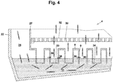
- the vacuum chamber 2 is laterally delimited by a wall 21 in which a door 20 is installed, an opposite wall 22, a rear wall 25 and a front wall 26.
- the Vacuum chamber has a bottom 24 and an in Fig. 2 Invisible ceiling 23.
- a seal is arranged between the door 20 and the wall 21, the rear wall 25, the front wall 26 and the ceiling 23, so that the vacuum chamber is sealed off from the environment when the door 20 is closed.
- the product chamber 7 has a chamber floor 30.
- the chamber floor 30 rests on a shoulder of the intermediate wall 27.
- the chamber floor 30 is only partially shown to show the steam introduction element 8, 9 of the steam condenser 4.
- the chamber bottom 30 covers the entire bottom surface of the product chamber 7.
- the chamber bottom 30 contains recesses 32 through which the steam generated in the product chamber during the vacuum cooling is passed into the steam condenser 4.
- the steam introduction element of the steam condenser 4 is arranged below the chamber floor 30.
- the steam introduction element consists of a plurality of channels 9, which are arranged in an intermediate floor 8.
- the channels protrude at least partially into the coolant. They contain openings 31 through which coolant can enter the channels 9. These openings are arranged on the channel floor, but can also be arranged in a side wall of the channel, which is in Fig. 4 is shown.
- the openings can be designed, for example, as circular holes, as slots or as a continuous opening. This means that the bottom of the channel 9 is completely open if the opening is designed as a continuous opening.
- the channels can also run inside tubular elements 39, which extend into the coolant below the intermediate base 8. In Fig.
- the tube element 39 is a cylinder with a tube plate, which is arranged in a plane which runs essentially parallel to the intermediate plate 8.
- the tube element 52 has a tube plate, which is arranged in a plane which extends at an angle to the intermediate plate. This means that the tube element 52 has a tube plate, which is immersed in the coolant at different points along its circumference at different depths.
- the channel 53 can also have a channel floor 10, which is arranged in a plane that extends at an angle to the intermediate floor 8.
- the steam is introduced into the tub 11 through the openings. In this way, the steam condenses and is absorbed by the coolant in the tub 11.
- the low-vapor air resulting from this condensation is conducted in the direction of the separation chamber 28.
- a separating element 29 is arranged in the separating chamber 28. Droplets are separated in the separating element 29, for example by being caught in a perforated plate, knitted fabric or woven fabric.
- the low-vapor air flows through the separating chamber 28 and is received by the vacuum line 6, which is not shown in this illustration.
- the cross-sectional area of the total of the openings of the channels is larger than the cross-sectional area of the vacuum line. This ensures that the flow velocity in the channels is lower than in the vacuum line 6.
- the channels 9 can have different depths. Depending on the level of the coolant, some of the channels cannot be immersed in the coolant.
- Fig. 3 shows a section of a steam condenser 4, which relates to a detail of a steam introduction element, which has an intermediate floor 8 with channels 9.
- the channels 9 project to different depths in the coolant.
- a channel is designed such that it no longer projects into the coolant at the coolant level shown. Since the steam now has less cross-sectional area available to get into the separation chamber 29, its flow rate increases.
- Fig. 4 Another variant of the steam condenser 4 is shown.
- the channels 9 of the intermediate floor 8 contain different types of openings.
- the openings 33 are designed, for example, as circular holes.
- the openings 34 are configured, for example, as elongated holes or slots.
- the channel 35 can also be open, that is to say have no channel bottom.
- lateral openings 36 can be made in the side walls of the channels 9 to be appropriate. According to this exemplary embodiment, too, the flow cross-sectional area for the steam from the product chamber 7 is dependent on the level of the coolant in the trough 11 of the steam condenser 4.
- the flow cross-section for the steam through the side openings 36 can be increased if the level of the coolant is chosen to be so high is that the side openings are at least partially covered.
- the steam can then enter the coolant through the side openings 36 and the openings at the channel bottom. If the openings are free of coolant, that is to say the level of the coolant is below the lateral openings 36, these openings serve for exchange with adjacent channel spaces. Since the steam can be introduced into the coolant unhindered by these channel spaces, the flow cross-sectional area for the steam increases, that is to say its flow velocity decreases when it passes through the openings of the channels and the channel spaces.
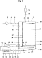
- Fig. 5 shows a variant of the Fig. 1 with heat recovery system.
- the coolant heated up to 60 ° can be passed through a heat exchanger 40 for the waste water cooling.
- the heat exchanger 40 can be arranged in a container 45 through which a fluid can circulate.
- This fluid can comprise a liquid or gaseous heat transfer fluid.
- the container 45 can in particular also be used as a waste water cooler.
- the used coolant which is loaded with impurities, is discharged via the coolant drain line 13 and introduced into the sewage system.
- the coolant Before being discharged into the sewage system, the coolant is cooled by being supplied to the heat exchanger 40. Furthermore, a heat exchanger 41 can be provided, which can be used for preheating a process fluid 43.
- the process fluid 43 to be preheated is passed through a preheater 46, which absorbs the heat of a heat exchange fluid 59 which leaves the heat exchanger 16 via the discharge line 48.
- the heat exchanger 16 for cooling the coolant located in the trough 11 of the steam condenser 4 is fed by the heat exchange fluid 49 via a feed line 47.
- This feed line 47 can either lead directly to the heat exchanger 16 or contain a branch which supplies the vacuum pump 3 with heat exchange fluid.
- the vacuum pump 3 can be cooled by means of the heat exchange fluid 49 if its operating temperature is exceeded.
- the heat exchange fluid 49 which leaves the vacuum pump, can optionally be fed into the feed line 47.
- Shut-off means 57, 58 can be provided in order to couple or decouple the cooling circuit of the vacuum pump 3 with the cooling circuit for the steam condenser 4.
- Fig. 6 shows a variant of the intermediate floor 50.
- the intermediate floor 50 is designed as a flat plate element inclined at an angle to the horizontal plane. This plate element is designed with openings 51, which allow the steam to pass from the product chamber 7 into the separation chamber 28.
- the intermediate floor 50 is at least partially immersed in the coolant located in the steam condenser.
- the flow cross section for the steam through the openings 51 can be increased if the level of the coolant rises, so that a larger part of the openings 51 are at least partially covered. The steam can then enter the coolant through the openings in the intermediate floor 50 above the level of the coolant.
- the openings are free of coolant, that is to say the level of the coolant lies below the openings 51, these openings serve to exchange the vapor space located on the underside of the intermediate floor. Since the steam can be introduced unhindered into the coolant from this steam space, the flow cross-sectional area for the steam increases, that is to say its flow velocity decreases as it passes through the openings in the intermediate floor 50 and the steam space. Accordingly, according to this exemplary embodiment, it is possible to consciously vary the level of the coolant in order to change the flow rate of the steam and therefore also the pressure loss. Therefore, by regulating the level of the coolant Pressure curve and thus the cooling behavior of the food can be influenced.
- FIG. 7 Another variant of the steam condenser 4 is shown.
- the channels 9 of the intermediate floor 8 are designed as tubular elements. These tubular elements can contain different types of openings.
- the openings 33 are designed, for example, as circular holes.
- the openings 34 are configured, for example, as elongated holes or slots.
- the channel can also be open, that is to say have no channel floor, which is not shown in the drawing.
- lateral openings 36 can be provided in the side walls of the channels 9. According to this exemplary embodiment, too, the flow cross-sectional area for the steam from the product chamber 7 is dependent on the level of the coolant in the trough 11 of the steam condenser 4.
- the flow cross-section for the steam through the side openings 36 can be increased if the level of the coolant is chosen to be so high is that the side openings are at least partially covered.
- the steam can then enter the coolant through the side openings 36 and the openings at the channel bottom. If the openings are free of coolant, that is to say the level of the coolant is below the lateral openings 36, these openings serve for exchange with adjacent channel spaces. Since the steam can be introduced into the coolant unhindered by these channel spaces, the flow cross-sectional area for the steam increases, that is to say its flow velocity decreases when it passes through the openings of the channels and the channel spaces.
- the vacuum cooling device 1 shown comprises a vacuum chamber 2, a vacuum source 3 and a steam condenser 4.
- the vacuum source 3 is a vacuum pump which is in fluid-conducting connection with the vacuum chamber 2 via a vacuum line 6.
- a valve 5 is arranged in the vacuum line 6.
- the vacuum chamber 2 contains a product chamber 7, which in the operating state contains the food to be cooled.
- the vacuum cooling device 1 contains a separation chamber 28.
- the separation chamber 28 is arranged next to the product chamber 7 and is separated from the product chamber by an intermediate wall 27.
- the vacuum chamber has in the region of the wall 21 or the wall 25 or the wall 26 a door, not shown, which is opened in order to place the food in the product chamber 7 and to remove it again from the product chamber 7 after the vacuum cooling has been completed.
- the product chamber 7 can be ventilated by means of a ventilation valve 18 which is arranged above the ceiling 23.
- the ventilation valve is connected to the product chamber 7 via a ventilation line.
- a filter element 19 is arranged in the ventilation line in order to filter out impurities from the fresh air, which can impair the quality of the food.
- the ventilation valve can be designed as a variable throttle element. It can be at least partially open during the cooling process.
- the ventilation valve is in the open state, so that an adequate supply of fresh air is ensured for people who are in the product chamber, even if the door of the vacuum chamber 2 is closed. Since moisture enters the product chamber together with the fresh air, the fresh air within the product chamber is deflected via a deflection element 38 in the direction of at least one of the walls 21, 25, 26, 27.
- the wall 26 is in Fig. 8 not visible since it lies in front of the plane of the drawing and the wall 25 forms the rear boundary of the product chamber 7.
- the two walls 25, 26 are in the Fig. 2 shown.
- the deflecting element can be equipped with drainage channels or it ends at its lowest point at a point from which the condensate directly to the chamber floor can drip. These measures can prevent the condensate from coming into contact with the food.
- the vacuum chamber 2 contains the steam condenser 4, which forms the bottom of the product chamber 7.
- the steam condenser 4 is separated from the product chamber 7 by the chamber floor 30.
- the chamber floor 30 therefore serves as a support for a rack trolley which carries the frames which form the support surfaces for the food.
- a channel floor 10 which is designed as a trough 11 filled with liquid.
- the liquid is a coolant which enters the tub 11 via the coolant supply line 12 and can at least partially leave the tub via a coolant drain line 13. Water is usually used as the coolant.
- a coolant valve 14 can be arranged in the coolant supply line 12, but this coolant valve is not necessarily provided. According to the present exemplary embodiment, the coolant is guided in a coolant circuit.
- the coolant circuit contains a heat exchanger which can be arranged in the tub 11 or outside the tub 11, for example in the separating chamber 28 or even outside the vacuum cooling device 1. Heat is extracted from the coolant by means of the heat exchanger 16. This heat can be reintroduced at another point in the processing process as part of heat recovery.
- the heat exchanger 16 can for example be designed as a plate heat exchanger.
- a plurality of heat exchangers can also be provided, which can be arranged in the trough 11, the separating chamber 28 or outside the vacuum cooling device 1.
- the chamber floor 30 contains at least one opening 31 through which the steam can enter the interior of the steam condenser 4.
- a coolant drain valve 15 is arranged in the coolant drain line 13.
- the level of the coolant in the tub 11 is controlled by a level control 17 such that there is a distance between the ramp and the liquid surface remains if 7 steam is generated in the product chamber, which must be condensed.
- a liquid flow occurs over the channel floor. This liquid flow is generated by coolant, which reaches the interior of the steam condenser 4 via a coolant inlet connection.
- the channel floor serves as a mass transfer area.
- the steam is introduced into the coolant flow and thus extracted from the air. At the same time, the heat transfer between steam and coolant takes place. Steam is understood here to mean a water vapor / air mixture which is sucked out of the product chamber 7 when a vacuum is applied via the vacuum line 6.
- Coolant and steam are in direct contact with one another, because the steam is transmitted from the opening or openings 31 to the surface of the coolant flow.
- the steam flows through the opening or openings 31 and into the liquid-filled trough 11.
- the water vapor portion condenses. Any impurities in the steam remain in the coolant, which is enriched with impurities.
- the coolant therefore serves as a filter section for the steam.
- the low-vapor air enters the separation chamber 28.
- the coolant enters the steam condenser 4 via the coolant inlet connection 54 below the chamber floor 30.
- the coolant flows along the channel floor 10, which is designed as a ramp and serves as a steam introduction element.
- the steam entering through the opening 31 flows parallel to the coolant along the channel floor 10. In this way, the steam is in direct contact with the coolant.
- a mass transfer takes place over the surface of the coolant flow by absorbing steam from the coolant flow.
- the coolant flow flows like a waterfall from the lower end of the channel floor 10 into the tub 11. This creates a spray layer, which further promotes the mass transfer. This means that a large part of the mass transfer can already have taken place when the circulated coolant from the lower end of the channel bottom enters the coolant located in the trough 11, which coolant collects at the bottom of the vacuum chamber.
- the end of the channel bottom can be immersed in the coolant.
- the coolant is fed via the coolant drain connection 55 into the one coolant outlet 56, which is led to the heat exchanger 16.
- the coolant flows through the heat exchanger and is cooled.
- the coolant passes from the heat exchanger via the coolant supply line 12 to a circulating pump 60 which conveys the coolant to the coolant inlet connection 54.
- the coolant circuit may include at least one shutoff device 61 to interrupt operation of the coolant circuit.
- the shutoff device 61 may also include a throttle valve to regulate the flow through the coolant outlet.
- a coolant valve 14 can also be provided, which can reduce the coolant flow through the heat exchanger or by means of which the flow through the heat exchanger can be slowed down in order to increase the residence time in the heat exchanger or the flow can be increased to increase the residence time in the Reduce heat exchanger.
- the coolant valve 14 and / or the shut-off device By means of the coolant valve 14 and / or the shut-off device, the flow of coolant through the heat exchanger and the circulated coolant volume can be regulated on the basis of a temperature measurement of the coolant or a level measurement of the coolant.
- This condensate drain also serves to periodically remove the contaminants that accumulate in the coolant from the system.
- the low-vapor air is passed through a separating element 29 located in the separating chamber 28.
- the steam flow which moves in the tub 11 in the direction of the separation chamber 28, can form a spray layer on the liquid surface.
- the separating element 29 is used.
- This separating element can be a droplet separator, which comprises, for example, in perforated sheet metal or a knitted fabric or fabric, on which droplets get caught.
- Several of these Separation elements can be arranged one behind the other and / or one above the other.
- the low-vapor air enters the vacuum line 6 and is sucked off via the vacuum pump 3.
- a heat exchanger can be provided in the separating chamber.
- This heat exchanger can be integrated in the coolant circuit.
- the heat exchanger can be used in order to bring about cooling or, if appropriate, further cooling of the coolant by heating the low-vapor air flow entering the vacuum pump 3.
- a cooling coil can be provided in the trough, which comprises finned tubular elements.
- These finned tube elements are advantageously protected from damage by an intermediate floor or by a permanently installed chamber floor 30, which can only be removed for assembly purposes or for maintenance work. If the finned pipe elements are freely accessible, there is a risk that these pipe elements will be entered by cleaning staff, for example during cleaning.
- the finned tube elements usually do not withstand such a load, especially if the fins are designed as thin-walled sheet metal parts.
Description
Die Erfindung betrifft eine Vakuumkühlvorrichtung für Lebensmittel, insbesondere Backwaren, welche zur Kondensation eines Dampfes, insbesondere von Wasserdampf, geeignet ist. Eine Vakuumkühlanlage zum Kühlen von Lebensmitteln, insbesondere Backwaren, beispielsweise frisch gebackenem Brot unter einem negativen Druck umfasst eine Vakuumkammer, die zur Aufnahme des frischen Lebensmittels für dessen Kühlung ausgebildet ist; eine Vakuumquelle, wie beispielsweise eine Vakuumpumpe, die mit der Vakuumkammer zum Ausstoßen von Dampf aus der Vakuumkammer und zur Erzeugung eines Unterdrucks in der Vakuumkammer verbunden ist sowie einen Dampfkondensator.The invention relates to a vacuum cooling device for food, in particular baked goods, which is suitable for the condensation of a vapor, in particular water vapor. A vacuum cooling system for cooling food, in particular baked goods, for example freshly baked bread under a negative pressure, comprises a vacuum chamber which is designed to hold the fresh food for cooling it; a vacuum source, such as a vacuum pump, connected to the vacuum chamber for ejecting steam from the vacuum chamber and creating a vacuum in the vacuum chamber, and a steam condenser.
Es sind Vorrichtungen zur Kondensation von Lösemitteldämpfen aus Vakuumdestillierapparaten oder Vakuumverdampfern aus der
Für Dampfmotoren ist ein Kondensator für Hochdruckdampf aus
Heisse und feuchte Lebensmittel können durch Evakuieren in einer Vakuumkammer sehr effizient abgekühlt werden, das heisst es ist nur eine kurze Abkühlungsdauer erforderlich. Allerdings fallen während des Evakuiervorgangs sehr grosse Volumina an Dampf an, welche ein Vielfaches des Kammervolumens betragen können. In einer Vakuumkammer, welche zwischen 4 und 6.6 m3 Kammervolumen aufweist, kann das Dampfvolumen beispielsweise bis 100 mal des Kammervolumens betragen.Hot and moist foods can be cooled very efficiently by evacuation in a vacuum chamber, which means that only a short cooling time is required. However, very large volumes of steam are generated during the evacuation process, which can be a multiple of the chamber volume. In a vacuum chamber, which has a chamber volume between 4 and 6.6 m 3 , the steam volume can be, for example, up to 100 times the chamber volume.
Die Leistung der Vakuumpumpe wird durch das anfallende Dampfvolumen bestimmt. Das heisst die Vakuumpumpe muss derart ausgelegt werden, dass die gesamte Dampfmenge die Vakuumkammer über die Vakuumpumpe verlässt. Ein Beispiel für eine Vakuumpumpe 1 für eine Vakuumkühlkammer 2 ist in der
Die
Die in der
Die
In der
Die
The
Im Stand der Technik wird daher der gesamte Wasserdampf mit der Vakuumpumpe in die Umgebung geleitet. Dementsprechend erhöht sich der Durchsatz durch die Vakuumpumpe um bis zu dem hundertfachen Wert des Luftdurchsatzes. Ein Teil des Wasserdampfs kann gezielt dafür genutzt werden, den Feuchtigkeitsgehalt der Backwaren zu erhöhen. Diese Lösung ist mit einem hohen Energieverbrauch verbunden. Dementsprechend muss eine Vakuumpumpe mit hoher Leistung eingesetzt werden. Die Pumpenleistung beträgt üblicherweise um die 45 kW.
Die Verwendung einer derart leistungsstarken Vakuumpumpe hat neben dem hohen Energieverbrauch eine ganze Reihe von Nachteilen im Betrieb.In the prior art, all of the water vapor is therefore conducted into the environment with the vacuum pump. Accordingly, the throughput through the vacuum pump increases by up to a hundred times the value of the air throughput. Part of the water vapor can be used specifically to determine the moisture content of the Increase baked goods. This solution is associated with high energy consumption. Accordingly, a high performance vacuum pump must be used. The pump output is usually around 45 kW.
In addition to the high energy consumption, the use of such a powerful vacuum pump has a number of disadvantages in operation.
Zumeist werden ölgeschmierte Vakuumpumpen vorgesehen, um das Dampfvolumen abzupumpen, weil sie einen hohen elektrischen Anschlusswert aufweisen. Während des Betriebs der Vakuumpumpe kommt der abzusaugende Dampf mit dem Schmieröl der Vakuumpumpe in Kontakt. Wenn der Dampf kondensiert, bevor er in die Vakuumpumpe gelangt oder im Innenraum der Vakuumpumpe kondensiert, kommt es zur Bildung eines Wasser-Öl-Gemisches, das eine stabile Emulsion ausbildet. Das Schmieröl muss deutlich über den Siedepunkt von Wasser erhitzt werden, um eine Emulsionsbildung zu verhindern. Das Schmieröl hat einen Siedepunkt von über 100°C. Der Siedepunkt des Wassers liegt darunter. Die Vakuumpumpe sollte daher über dem Siedepunkt des Wassers betrieben werden. Hierzu sollte die gesamte Vakuumpumpe, die mit dem Dampf in Berührung kommt, eine Temperatur aufweisen, die über dem Siedepunkt des Wassers liegt, das heisst das Wasser verdampft unter atmosphärischen Bedingungen. Hierzu ist es erforderlich, dass die Vakuumpumpe läuft, auch wenn sie gerade nicht für die Vakuumbildung benötigt wird, damit die notwendige Wärme erzeugt wird. Eine Ölemulsion kann entstehen, solange sich Dampf in der Vakuumkammer befindet, auch wenn die Vakuumkammer nicht mehr zur Durchführung einer Vakuumkühlung verwendet wird. Daher sollte die Vakuumpumpe mindestens eine Stunde lang weiter laufen, nachdem der letzte Vakuumkühlvorgang abgeschlossen ist. Die Vakuumpumpe sollte auch mindestens eine Stunde vorzugsweise mindestens 90 Minuten, besonders bevorzugt mindestens zwei Stunden früher in Betrieb genommen werden, damit sie die notwendige Betriebstemperatur erreicht.Oil-lubricated vacuum pumps are usually provided to pump out the steam volume because they have a high electrical connection value. During the operation of the vacuum pump, the steam to be extracted comes into contact with the lubricating oil of the vacuum pump. If the steam condenses before it enters the vacuum pump or condenses inside the vacuum pump, a water-oil mixture is formed which forms a stable emulsion. The lubricating oil must be heated well above the boiling point of water to prevent the formation of an emulsion. The lubricating oil has a boiling point of over 100 ° C. The boiling point of the water is below that. The vacuum pump should therefore be operated above the boiling point of the water. For this purpose, the entire vacuum pump that comes into contact with the steam should have a temperature that is above the boiling point of the water, i.e. the water evaporates under atmospheric conditions. For this it is necessary that the vacuum pump is running, even if it is not currently needed for the vacuum formation, so that the necessary heat is generated. An oil emulsion can form as long as there is steam in the vacuum chamber, even if the vacuum chamber is no longer used to perform vacuum cooling. Therefore, the vacuum pump should continue to run for at least an hour after the last vacuum cooling process is complete. The vacuum pump should also be started up at least one hour, preferably at least 90 minutes, particularly preferably at least two hours, so that it reaches the necessary operating temperature.
Der Vakuumpumpe kann ein Abscheider nachgeschaltet sein, um den Wasserdampf zu kondensieren. Wenn in der Vakuumpumpe bereits Wasserdampf kondensiert, nimmt dieser Wasserdampf Schmieröl auf. Daher befinden sich im Wasserdampfkondensat klebrige Schmierölrückstände, die in den Wasserablauf gelangen können. Da die Ölemulsion, die durch den kondensierenden Wasserdampf in der Vakuumpumpe gebildet wird, stabil ist, kann sie unter Umständen nicht durch einen konventionellen Ölfilter abgeschieden werden. Die zum Einsatz kommenden Abscheider sind voluminös, aufwändig zu entwässern und zu reinigen.A separator can be connected downstream of the vacuum pump in order to condense the water vapor. If water vapor already condenses in the vacuum pump, this water vapor absorbs lubricating oil. Therefore, there are sticky lubricating oil residues in the water vapor condensate that run into the water drain can reach. Since the oil emulsion formed by the condensing water vapor in the vacuum pump is stable, it may not be possible to separate it using a conventional oil filter. The separators used are voluminous, complex to drain and clean.
Die Verwendung einer leistungsstarken Vakuumpumpe kann auch dazu führen, dass Verunreinigungen, wie Schmutzpartikel, Lebensmittelfette und andere Backrückstände aus der Vakuumkammer abgesaugt werden. Filter können in der Vakuumleitung zwischen der Vakuumkammer und der Vakuumpumpe eingebaut sein, um zu verhindern, dass diese Verunreinigungen in die Vakuumpumpe gelangen können. Jeder Filter in der Vakuumleitung erhöht allerdings den Druckverlust, was in Bereichen von 200 bis 300 mbar noch einen vernachlässigbaren Effekt darstellt, allerdings bei Drücken von unter 20 mbar, insbesondere unter 5 mbar und darunter eine deutliche Erhöhung der Pumpenleistung erfordert, damit eine Evakuierung im unteren Vakuumbereich erfolgen kann.Using a powerful vacuum pump can also cause contaminants such as dirt particles, food fats and other baking residues to be sucked out of the vacuum chamber. Filters can be installed in the vacuum line between the vacuum chamber and the vacuum pump to prevent these contaminants from getting into the vacuum pump. However, each filter in the vacuum line increases the pressure loss, which is still a negligible effect in the range from 200 to 300 mbar, but at pressures below 20 mbar, in particular below 5 mbar and below, requires a significant increase in the pump output, so that evacuation in the lower range Vacuum area can take place.
Das Kondensat des aus der Vakuumkammer abgesaugten Dampfes ist sehr sauer und Maschinenteile der Vakuumpumpe aus Stahl können korrodieren, wenn sie in Kontakt mit dem Kondensat kommen. Es ist zwar möglich, Vakuumpumpenteile sowie Filter oder Abscheider aus rostfreiem Stahl einzusetzen. Allerdings hat sich gezeigt, dass es an Stellen, wo sich Kondensat in einer Totzone ansammelt, auch Edelstahlelemente korrodieren können. Um die Öltemperatur ständig über dem Siedepunkt des Wassers halten zu können, muss die Vakuumpumpe zwangsläufig immer eingeschaltet sein. Dies führt zu einem zusätzlichen Energieverbrauch, denn die Vakuumpumpe bleibt eingeschaltet, selbst wenn sie für das Vakuumkühlverfahren nicht benötigt wird.The condensate of the vapor extracted from the vacuum chamber is very acidic and machine parts of the steel vacuum pump can corrode if they come into contact with the condensate. It is possible to use vacuum pump parts as well as filters or separators made of stainless steel. However, it has been shown that stainless steel elements can also corrode in places where condensate collects in a dead zone. In order to keep the oil temperature constantly above the boiling point of the water, the vacuum pump must always be switched on. This leads to additional energy consumption because the vacuum pump remains switched on, even if it is not required for the vacuum cooling process.
Der Verlauf des Kühlverfahrens kann die Qualität des vakuumgekühlten Lebensmittels beeinflussen. Der Verlauf des Kühlverfahrens wird insbesondere eine Regelung des Drucks in der Vakuumkammer sowie gegebenenfalls eine Regelung der Temperatur festgelegt und überwacht. Im Stand der Technik erfolgt die Druckregelung gemäss einer Regelungsvorschrift, die den Verlauf des Drucks über der Zeit abbildet, das heisst einer Druckkurve. Die Druckkurve wird durch die Rezeptur der jeweiligen Lebensmittel bestimmt. Bisher musste der Druck über ein Ventil zweipunktgeregelt werden. Das Ventil weist im Wesentlichen zwei Betriebszustände auf, den geschlossenen Zustand, in welchem die Verbindung zur Vakuumpumpe unterbrochen ist und den offenen Zustand, in welchem die Verbindung zu Vakuumpumpe besteht und Dampf aus der Vakuumkammer abgesaugt werden kann. Das heisst einer der Punkte der Zweipunktregelung entspricht dem geschlossenen Ventil, ein zweiter der Punkte der Zweipunktregelung entspricht dem geöffneten Ventil. Wenn das Ventil öffnet, erfolgt die Reduktion des Drucks schlagartig. Diese schlagartige Druckverringerung kann dazu führen, dass Feuchtigkeit aus dem Lebensmittel austritt und in den Dampfkreislauf gelangt. Daher können viele Lebensmittel mit dieser Zweipunktregelung nicht optimal gekühlt werden. Eine Qualitätseinbusse der Lebensmittel muss dadurch in Kauf genommen werden. Die Vakuumpumpe muss zudem für diese einfache Zweipunktregelung kontinuierlich ohne Unterbrechung laufen.The course of the cooling process can influence the quality of the vacuum-cooled food. The course of the cooling process, in particular a regulation of the pressure in the vacuum chamber and, if necessary, a regulation of the temperature are determined and monitored. In the prior art, pressure control is carried out in accordance with a regulation that maps the course of the pressure over time, that is to say a pressure curve. The pressure curve is shown by the Recipe of the respective food determined. Previously, the pressure had to be controlled using a two-point valve. The valve has essentially two operating states, the closed state in which the connection to the vacuum pump is interrupted and the open state in which the connection to the vacuum pump exists and steam can be sucked out of the vacuum chamber. That means one of the points of the two-point control corresponds to the closed valve, a second of the points of the two-point control corresponds to the open valve. When the valve opens, the pressure is reduced suddenly. This sudden drop in pressure can lead to moisture escaping from the food and entering the steam cycle. Therefore, many foods cannot be optimally cooled with this two-point control. A loss of quality in the food must be accepted. For this simple two-point control, the vacuum pump must also run continuously without interruption.
Der vorliegenden Erfindung liegt die Aufgabe zugrunde, einen Dampfkondensator sowie eine Vakuumkühlvorrichtung mit einem Dampfkondensator zu entwickeln, mittels welchem ein grosser Teil des in der Vakuumkammer entstehenden Dampfs kondensiert werden kann, ohne dass es zu einer Kontamination der Vakuumpumpe kommt. Es ist eine weitere Aufgabe der Erfindung, den Leistungsbedarf der Vakuumpumpe zu verringern.The present invention has for its object to develop a steam condenser and a vacuum cooling device with a steam condenser, by means of which a large part of the steam generated in the vacuum chamber can be condensed without causing contamination of the vacuum pump. It is another object of the invention to reduce the power requirement of the vacuum pump.
Die Aufgabe wird durch eine Vakuumkühlvorrichtung nach Anspruch 1 gelöst. Weitere vorteilhafte Ausführungsbeispiele sind Gegenstand der Unteransprüche 2 bis 7. Ein Verfahren zur Lösung der Aufgabe der Erfindung ist Gegenstand der Ansprüche 8 bis 13.The object is achieved by a vacuum cooling device according to
Eine Vakuumkühlvorrichtung zur Kühlung von Lebensmitteln, insbesondere heissen Backwaren umfasst eine Vakuumkammer, die eine Produktkammer zur Aufnahme des Lebensmittels für dessen Kühlung und eine Abscheidekammer enthält. Des Weiteren enthält die Vakuumkühlvorrichtung eine Vakuumquelle, wie beispielsweise eine Vakuumpumpe, die mit der Abscheidekammer verbunden ist, und einen Dampfkondensator zur Kondensation von in der Produktkammer während des Abkühlvorgangs entstehendem Dampf. Der Dampfkondensator enthält ein Kühlmittel in einer Wanne und umfasst ein Dampfeinleitungselement zur Einleitung des Dampfes in das Kühlmittel. Der Dampfkondensator ist unmittelbar unter der Produktkammer angeordnet, um den Dampf aus der Produktkammer aufzunehmen. Es ist auch möglich, dass der Dampfkondensator zwar mit der Produktkammer in fluidleitender Verbindung steht, aber baulich von der Produktkammer getrennt ist, ja sogar als separates Modul ausgeführt sein kann.A vacuum cooling device for cooling food, in particular hot baked goods, comprises a vacuum chamber which contains a product chamber for receiving the food for cooling it and a separating chamber. The vacuum cooling device further includes a vacuum source, such as a vacuum pump, connected to the separation chamber, and a steam condenser for condensing in the product chamber during the Steam generated during the cooling process. The steam condenser contains a coolant in a trough and comprises a steam introduction element for introducing the steam into the coolant. The steam condenser is located immediately below the product chamber to receive the steam from the product chamber. It is also possible that the steam condenser is in fluid-conducting connection with the product chamber, but is structurally separate from the product chamber, and can even be designed as a separate module.
Nach einem Ausführungsbeispiel ist das Dampfeinleitungselement unterhalb eines Kammerbodens angeordnet. Der Kammerboden dient der Aufnahme der Gebinde für die Lebensmittel, insbesondere Gestelle, Regale, Stikkenwagen oder dergleichen. Das Dampfeinleitungselement umfasst eine Mehrzahl von Kanälen oder Rohrelementen, welche teilweise in das Kühlmittel hineinragen. Das heisst, das Kühlmittel umgibt die Kanäle oder Rohrelemente zumindest teilweise. Insbesondere kann der Dampfkondensator als Bestandteil der Vakuumkammer ausgebildet sein. Insbesondere ist der Dampfkondensator als eine Filterstrecke für das Rückhalten von Verunreinigungen im Dampf ausgebildet.According to one embodiment, the steam introduction element is arranged below a chamber floor. The chamber floor serves to hold the containers for the food, in particular racks, shelves, rack trolleys or the like. The steam introduction element comprises a plurality of channels or pipe elements which partially protrude into the coolant. This means that the coolant at least partially surrounds the channels or pipe elements. In particular, the steam condenser can be designed as part of the vacuum chamber. In particular, the steam condenser is designed as a filter section for the retention of impurities in the steam.
Nach einem Ausführungsbeispiel kann eine Regelungseinheit für die Kondenswassermenge und/oder die Kondenswassertemperatur vorgesehen sein. Hierdurch kann sichergestellt werden, dass die Kanäle oder Rohrelemente immer in das Kühlmittel eintauchen. Das heisst, der Dampf, der von oben in die Kanäle oder Rohrelemente eintritt, muss auf dem Weg zur Vakuumpumpe durch das Kühlmittel hindurch treten, wobei der Dampf im Kühlmittel kondensiert. Ebenso kondensieren allfällige mit dem Dampf mitgeführte Verunreinigungen. Das restliche Gas, also die dampfarme Luft, tritt in die Abscheidekammer ein. In der Abscheidekammer kann ein Abscheideelement angeordnet sein. Wenn die dampfarme Luft das Kühlmittel verlässt, bildet sich eine Spritzschicht aus. Das Abscheideelement dient zum Auffangen der Tropfen aus der Spritzschicht und verhindert somit, dass Flüssigkeit in die Vakuumleitung eingesaugt wird und zur Vakuumquelle gelangt. Die Vakuumquelle umfasst eine Vakuumpumpe, wobei die Vakuumpumpe insbesondere eine drehzahlgeregelte Vakuumpumpe ist. Durch die Anpassung der Drehzahl kann der Druckverlauf genau geregelt werden. Somit können beliebige Druckverläufe der Druckverlauf genau geregelt werden. Somit können beliebige Druckverläufe realisiert werden, indem die Drehzahl der Vakuumpumpe entsprechend angepasst wird.According to one embodiment, a control unit for the amount of condensed water and / or the condensed water temperature can be provided. This can ensure that the channels or pipe elements are always immersed in the coolant. This means that the steam that enters the channels or pipe elements from above must pass through the coolant on the way to the vacuum pump, the steam condensing in the coolant. Any contaminants carried along with the steam also condense. The remaining gas, i.e. the low-vapor air, enters the separation chamber. A separating element can be arranged in the separating chamber. When the low-vapor air leaves the coolant, a spray layer forms. The separating element serves to catch the drops from the spray layer and thus prevents liquid from being sucked into the vacuum line and reaching the vacuum source. The vacuum source comprises a vacuum pump, the vacuum pump being in particular a speed-controlled vacuum pump. The pressure curve can be precisely regulated by adjusting the speed. This means that any pressure gradients the pressure curve can be precisely regulated. Any desired pressure curves can be realized by adjusting the speed of the vacuum pump accordingly.
Nach einem Ausführungsbeispiel enthält die Wanne einen Wärmetauscher, sodass die Kondensationswärmeenergie in einer Wärmerückgewinnungsanlage wieder verwendbar ist. Die im Dampfkondensator entstehende Wärme kann somit für andere Prozessschritte genutzt werden. Zwar ist die Rückgewinnung von Wärme aus einer Anwendung für Dampfsterilisatoren aus der
Ein Verfahren zur Vakuumkühlung eines Lebensmittels umfasst die Schritte: Befüllen einer Produktkammer einer Vakuumkühlvorrichtung mit dem Lebensmittel, Schliessen der Produktkammer, Betätigen einer Vakuumquelle zur Erzeugung eines negativen Drucks, Entnahme des gekühlten Lebensmittels. In der Produktkammer wird durch das Abkühlen des Lebensmittels entweichende Dampf in einem Dampfkondensator kondensiert.A method for vacuum cooling a food comprises the steps: filling a product chamber of a vacuum cooling device with the food, closing the product chamber, actuating a vacuum source to generate a negative pressure, removing the cooled food. In the product chamber, steam escaping as the food cools is condensed in a steam condenser.
Erfindungsgemäß enthält der Dampfkondensator ein Kühlmittel in einer Wanne, sodass der Dampf in ein Dampfeinleitungselement geführt wird und in das Kühlmittel eingeleitet wird. Hierbei wird das Kühlmittel mit Dampf beladen und der Dampf enthält einen Wasseranteil, welcher im Kühlmittel kondensiert. Das Kühlmittel kann insbesondere Wasser sein.According to the invention, the steam condenser contains a coolant in a trough, so that the steam is guided into a steam introduction element and is introduced into the coolant. Here, the coolant is loaded with steam and the steam contains a proportion of water which condenses in the coolant. The coolant can in particular be water.
Das Kühlmittel kann periodisch oder aufgrund des Erreichens eines vorgegebenen Grenzwertes ausgetauscht werden, insbesondere wenn dessen Temperatur zu hoch wird, die Konzentration an Verunreinigungen einen Maximalwert erreicht oder der pH-Wert auf 4 oder weniger gesunken ist. Somit können die Verunreinigungen im Dampfkondensator gesammelt werden und mit dem Kühlmittel entsorgt werden oder einer nachgeschalteten Entsorgungsanlage zugeführt werden.The coolant can be replaced periodically or because a predetermined limit value has been reached, in particular if its temperature becomes too high, the concentration of impurities has reached a maximum value or the pH value has dropped to 4 or less. Thus, the impurities in the Steam condenser are collected and disposed of with the coolant or fed to a downstream disposal system.
Nach einem Ausführungsbeispiel kann die Kühlung des Kühlmittels mittels eines Wärmetauschers erfolgen, der beispielsweise mit Frischwasser gespeist wird. Nach einem Ausführungsbeispiel kondensieren zumindest 60%, bevorzugt zumindest 90% des Wasseranteils im Dampf im Dampfkondensator. Insbesondere können im Dampf befindliche Verunreinigungen im Kondensat angereichert werden und mit dem Kondensat ausgetragen werden. Diese Variante ermöglicht insbesondere eine einfache Reinigung.According to one embodiment, the coolant can be cooled by means of a heat exchanger which is fed, for example, with fresh water. According to one embodiment, at least 60%, preferably at least 90%, of the water content in the steam condenses in the steam condenser. In particular, contaminants in the steam can be accumulated in the condensate and discharged with the condensate. This variant enables easy cleaning in particular.
Ein Dampfkondensator für eine Vakuumkühlvorrichtung nach einem der vorhergehenden Ausführungsbeispiele enthält eine Wanne, die im Betriebszustand ein Kühlmittel enthält und umfasst ein Dampfeinleitungselement zur Einleitung des Dampfes in das Kühlmittel, sodass der Dampf und das Kühlmittel in direktem Kontakt stehen.A steam condenser for a vacuum cooling device according to one of the preceding exemplary embodiments contains a trough which contains a coolant in the operating state and comprises a steam introduction element for introducing the steam into the coolant so that the steam and the coolant are in direct contact.
Der Dampfkondensator enthält somit eine Wanne, die einen Dampfraum und einen Ansaugraum aufweist, wobei der Dampfraum durch einen Kammerboden begrenzt ist. Der Kammerboden enthält mindestens eine Öffnung. Durch diese Öffnung kann im Betriebszustand Dampf in den Dampfraum eintreten. Der Betriebsdruck in der Wanne ist kleiner als der Umgebungsdruck. Die Wanne enthält im Betriebszustand ein Kühlmittel. Der Dampfkondensator enthält ein Dampfeinleitungselement zur Einleitung des Dampfes in das Kühlmittel. Das Dampfeinleitungselement ist in der Wanne unterhalb des Kammerbodens angeordnet. Das Dampfeinleitungselement kann ein Kanalelement, welches eine Mehrzahl von Kanälen enthält, Rohrelemente, ein Plattenelement oder einen Kanalboden umfassen. Das Dampfeinleitungselement kann teilweise in das in der Wanne befindliche Kühlmittel hineinragen oder oberhalb des Flüssigkeitsspiegels des Kühlmittels angeordnet sein, wobei ein Kühlmittelstrom entlang des Dampfeinleitungselements fliessen kann. Das Dampfeinleitungselement kann zumindest eine Öffnung enthalten, sodass der Flüssigkeitsspiegel des Kühlmittels im Dampfeinleitungselement dem Flüssigkeitsspiegel des Kühlmittels in der Wanne entspricht. Die Wanne weist ein Trennelement auf, welches den Dampfraum von einem Ansaugraum trennt, wobei der Ansaugraum an eine Vakuumerzeugungseinrichtung anschliessbar ist, sodass der Dampf vom Dampfraum mittels des Dampfeinleitungselements in dem Kühlmittel aufnehmbar ist, wenn durch die Vakuumerzeugungseinrichtung im Ansaugraum ein Unterdruck erzeugbar ist. Der Wasseranteil des Dampfes kondensiert im Kühlmittel zu einem grossen Teil. Ein dampfarmer Luftstrom verlässt die Wanne in Richtung Ansaugraum. Vorteilhafterweise ist der Flüssigkeitsspiegel des Kühlmittels derart, dass das Trennelement in das Kühlmittel ragt. Hierdurch wird der Dampf gezwungen, einen Weg durch das Kühlmittel vom Dampfraum in den Ansaugraum zu nehmen. Das Trennelement kann als eine Wand der Abscheidekammer ausgebildet sein.The steam condenser thus contains a trough which has a steam space and a suction space, the steam space being delimited by a chamber floor. The chamber floor contains at least one opening. Through this opening, steam can enter the steam chamber in the operating state. The operating pressure in the tub is less than the ambient pressure. The tub contains a coolant in the operating state. The steam condenser contains a steam introduction element for introducing the steam into the coolant. The steam introduction element is arranged in the trough below the chamber floor. The steam introduction element can comprise a duct element which contains a plurality of ducts, tubular elements, a plate element or a duct base. The steam introduction element can partially protrude into the coolant located in the trough or can be arranged above the liquid level of the coolant, wherein a coolant flow can flow along the steam introduction element. The steam introduction element can contain at least one opening, so that the liquid level of the coolant in the steam introduction element corresponds to the liquid level of the coolant in the tub. The tub has a separating element, which the Separates the vapor space from a suction space, the suction space being connectable to a vacuum generating device, so that the steam can be absorbed in the coolant by means of the steam introduction element if a vacuum can be generated in the suction space by the vacuum generating device. The water part of the steam condenses to a large extent in the coolant. A low-steam air flow leaves the tub in the direction of the intake chamber. The liquid level of the coolant is advantageously such that the separating element projects into the coolant. This forces the steam to take a path through the coolant from the steam room to the intake room. The separating element can be designed as a wall of the separation chamber.
Das Dampfeinleitungselement ist bevorzugt unterhalb eines Kammerbodens angeordnet, der zur Aufnahme der Lebensmittel dient. Insbesondere umfasst das Dampfeinleitungselement eine Mehrzahl von Kanälen oder Rohrelementen, welche teilweise in das Kühlmittel hineinragen. Der Dampf kann Verunreinigungen enthalten, die vom Kühlmittel aufnehmbar sind, sodass das Kühlmittel als eine Filterstrecke für das Rückhalten der Verunreinigungen ausgebildet ist.The steam introduction element is preferably arranged below a chamber bottom, which serves to hold the food. In particular, the steam introduction element comprises a plurality of channels or pipe elements which partially protrude into the coolant. The steam can contain contaminants that can be absorbed by the coolant, so that the coolant is designed as a filter section for the retention of the contaminants.
Auf eine Zufuhr von Feuchtigkeit, das heisst zusätzlichem Wasser oder Wasserdampf beispielsweise in der Form von Sprühnebeln in die Vakuumkammer kann verzichtet werden. Eine Erhöhung des Wassergehalts der Backwaren kann vorgesehen werden, wenn die Backwaren eine besonders feuchte Oberfläche aufweisen müssen. Der Wassergehalt ist in den Backwaren erwünscht, weil der Backvorgang hierdurch schneller abgeschlossen werden kann. Allerdings kann eine zu starke Druckdifferenz, insbesondere eine schlagartige Druckabsenkung wie sie mit einer Zweipunktregelung auftreten kann, dazu führen, dass die Feuchtigkeit aus dem Inneren der Lebensmittel an deren Oberfläche gelangt und von dort in die Vakuumkammer und mit dem Dampfkreislauf zu dem Dampfkondensator.A supply of moisture, that is to say additional water or water vapor, for example in the form of spray mist, into the vacuum chamber can be dispensed with. An increase in the water content of the baked goods can be provided if the baked goods have to have a particularly moist surface. The water content in the baked goods is desirable because this enables the baking process to be completed more quickly. However, an excessive pressure difference, in particular a sudden drop in pressure as can occur with a two-point control, can result in the moisture from inside the food reaching its surface and from there into the vacuum chamber and with the steam circuit to the steam condenser.
Der Dampfkondensator ist gemäss einem Ausführungsbeispiel ein Bestandteil der Vakuumkammer. Der Dampfkondensator enthält gemäss diesem Ausführungsbeispiel ein Wasserbad am Boden der Vakuumkammer. Gleichzeitig dient der Dampfkondensator als Schmutzfilter, da mit dem Dampf mitgeführte Schmutzpartikel im Wasserbad kondensieren und mit dem Kondensat ausgetragen werden können. Derartige Schmutzfilter sind beispielsweise auf dem Gebiet des Staubsaugens bekannt. Die
Die Kondensationswärmeenergie kann genutzt werden, das heisst es kann eine Vorrichtung zur Wärmerückgewinnung vorgesehen sein. Diese Wärmerückgewinnung kann zur Erwärmung oder zum Vorwärmen des Prozesswassers verwendet werden. Während der Vakuumkühlung verdampft Wasser in den Lebensmitteln und deshalb werden diese abgekühlt. Der Verarbeitungsprozess für Backwaren läuft wie folgt ab: Die Backwaren werden bis zu 60 min gebacken, wobei es nach circa 2/3 der zur Verfügung stehenden Zeit ein Trocknungsvorgang an den Backvorgang anschliesst. Das heisst, gemäss diesem Beispiel würde der Backvorgang ca. 40 min und der Trocknungsvorgang ca. 20 min in Anspruch nehmen.The heat of condensation energy can be used, that is, a device for heat recovery can be provided. This heat recovery can be used to heat or preheat the process water. Water evaporates in the food during vacuum cooling and is therefore cooled. The processing process for baked goods is as follows: The baked goods are baked for up to 60 minutes, with a drying process following the baking process after approximately 2/3 of the time available. This means that, according to this example, the baking process would take about 40 minutes and the drying process about 20 minutes.
Das ganze Wasserdampfvolumen wird durch ein Wasserbad innerhalb der Vakuumkammer geleitet, dadurch kondensiert der Dampf und erwärmt das Wasser. Die anfallende Wärmeenergie kann mit einer Kältemaschine dem Wasserbad entzogen und kann z.B. für die Warmwasseraufbereitung oder für Heizzwecke, genutzt werden.The entire volume of water vapor is passed through a water bath inside the vacuum chamber, which causes the steam to condense and heat the water. The heat energy generated can be removed from the water bath with a chiller and can e.g. for hot water preparation or for heating purposes.
Die Temperatur des Wasserbades wird überwacht und garantiert einen reproduzierbaren Vakuumprozess. Das Wasserbad hat eine gute Filterwirkung, dadurch können Backrückstände nicht in die Vakuumpumpe gelangen.The temperature of the water bath is monitored and guarantees a reproducible vacuum process. The water bath has a good filter effect, which means that baking residues cannot get into the vacuum pump.
Das anfallende Kondenswasser ist sauer und wird im Wasserbad verdünnt, da der Wasseranteil des Dampfs vom Kühlmittel aufgenommen wird. Da als Kühlmittel bevorzugt Wasser eingesetzt wird, erfolgt eine Verdünnung des sauren Kondenswassers in dem in der Wanne befindlichen Kühlmittel.
Das Kühlmittel wird über eine Kühlmittelablassleitung abgelassen. Durch sporadisches Abschlämmen des Kühlmittels werden im Kühlmittel, das heisst im Wasser gelöste Backrückstände abgeführt.The condensed water is acidic and is diluted in a water bath because the water part of the steam is absorbed by the coolant. Since water is preferably used as the coolant, the acidic condensed water is diluted in the coolant located in the tub.
The coolant is drained off via a coolant drain line. Sporadic draining of the coolant removes baking residues dissolved in the coolant, that is, in the water.
Da die Verunreinigungen, wie Backrückstände sich mit der Zeit im Kühlmittel und daher in der Wanne des Dampfkondensators ansammeln, kann es zu Beeinträchtigungen beim Betrieb des Dampfkondensators kommen. Daher erfolgt mit dem Nachfüllen des Wasserbades ein interner Reinigungsprozess der Vakuumkammer, das heisst der Abscheidekammer, der Produktkammer sowie des Dampfkondensators.Since the contaminants, such as baking residues, accumulate over time in the coolant and therefore in the trough of the steam condenser, there may be impairments in the operation of the steam condenser. For this reason, when the water bath is refilled, the vacuum chamber is cleaned internally, i.e. the separation chamber, the product chamber and the steam condenser.
Eine direkte Bypassverbindungsleitung zwischen Vakuumkammer und Vakuumleitung kann vorgesehen sein, welche durch ein Bypassventil geöffnet oder geschlossen werden kann. Wenn das Bypassventil geöffnet ist, wird der Dampf nicht über den Kondensator geführt, sondern direkt in die Vakuumleitung eingeleitet. Diese Bypassverbindungsleitung kann am Ende des Vakuumkühlvorgangs eingesetzt werden, wenn der Dampf nur noch wenig Feuchtigkeit enthält. Da der Druckverlust durch den Kondensator entfällt, wenn der Dampf aus der Vakuumkammer direkt in die Vakuumleitung geführt wird, können niedrigere Drücke in der Vakuumkammer erreicht werden.A direct bypass connection line between the vacuum chamber and the vacuum line can be provided, which can be opened or closed by a bypass valve. When the bypass valve is open, the steam is not passed through the condenser, but is fed directly into the vacuum line. This bypass connection line can be used at the end of the vacuum cooling process if the steam contains little moisture. Since the pressure loss through the condenser is eliminated when the steam is led from the vacuum chamber directly into the vacuum line, lower pressures can be achieved in the vacuum chamber.
Die erfindungsgemässen Ausführungsbeispiele haben zumindest einige der nachgenannten Vorteile: Die Vakuumkammer und der Dampfkondensator insbesondere das Wasserbad, sind nach einem Ausführungsbeispiel eine Einheit, sodass ein zusätzlicher Druckbehälter entfällt, was Kostenvorteile bringt.
Das Kühlmittel dient gleichzeitig als Filterstrecke, um mit dem Dampf mitgerissene Verunreinigungen aus der Produktkammer im Kühlmittel durch Kondensation abzuscheiden.The exemplary embodiments according to the invention have at least some of the advantages mentioned below: according to one exemplary embodiment, the vacuum chamber and the steam condenser, in particular the water bath, are one unit, so that an additional pressure vessel is omitted, which brings cost advantages.
The coolant also serves as a filter section in order to separate contaminants entrained in the steam from the product chamber in the coolant by condensation.
Es können trocken laufende Vakuumpumpen eingesetzt werden, da die dampfarme Luft, die von der Abscheidekammer angesaugt wird, einen allenfalls niedrigen Wasserdampfgehalt sowie keine Verunreinigungen enthält.
Das saure Kondensat wird verdünnt, indem es im Dampfkondensator vom Kühlmittel Wasser aufgenommen wird. Hierdurch wird die Gefahr von Schäden durch Korrosion an den Bauteilen verringert, die mit dem Kondensat in Kontakt sind.
Die Kondensierungswärmeenergie kann im Produktionsprozess genutzt werden, beispielsweise als Vorwärmer.
Der Vakuumprozess ist reproduzierbar. Beispielsweise kann der Verlauf der Vakuumkühlung beispielsweise als Druckverlauf in Abhängigkeit von der Abkühlzeit in einer elektronischen Kontrolleinheit gespeichert werden und immer wieder abgerufen werden und erlaubt durch die genaue Regelung der Vakuumpumpe Chargen mit gleichen Produkteigenschaften zu erhalten.
Eine automatische Reinigung des Dampfkondensators sowie der Produktkammer und/oder der Abscheidekammer erfolgt durch Austausch des Wassers.
Die Vakuumpumpe wird energieeffizient eingesetzt, da sie nur während dem Vakuumprozess im Lastbetrieb eingeschaltet ist.Dry-running vacuum pumps can be used because the low-vapor air that is drawn in by the separation chamber contains at most a low water vapor content and no impurities.
The acidic condensate is diluted by being taken up by the coolant water in the steam condenser. This reduces the risk of corrosion damage to the components that are in contact with the condensate.
The condensation heat energy can be used in the production process, for example as a preheater.
The vacuum process is reproducible. For example, the course of the vacuum cooling, for example as a pressure course depending on the cooling time, can be stored in an electronic control unit and called up again and again and allows batches with the same product properties to be obtained by the precise control of the vacuum pump.
The steam condenser and the product chamber and / or the separating chamber are cleaned automatically by exchanging the water.
The vacuum pump is used in an energy-efficient manner since it is only switched on during the vacuum process in load operation.
Mit einer drehzahlgeregelten Vakuumpumpe können alle Lebensmittel gekühlt werden, das heisst es kann ein beliebiger Verlauf der Vakuumkühlung realisiert werden, insbesondere kann eine zusätzliche Befeuchtung der Lebensmittel entfallen. Ist der Dampfkondensator als Teil der Vakuumkühlvorrichtung ausgebildet, entfällt ein zusätzlicher Druckbehälter für die Wasserabscheidung in der Vakuumleitung. Die Vakuumpumpe ist fast ausschliesslich während der Kühlperiode in Betrieb, da das Vakuum über die Drehzahl geregelt werden kann und die Abluft aus der Vakuumkammer im Wesentlichen frei von Dampf ist. Die Vakuumpupe muss nicht abgestellt werden, sie kann im Bereitschaftsbetrieb weiterlaufen. Im Bereitschaftsbetrieb verrichtet die Vakuumpumpe keine Arbeit.With a speed-controlled vacuum pump, all foods can be cooled, which means that any course of vacuum cooling can be implemented, in particular additional humidification of the foods can be omitted. If the steam condenser is designed as part of the vacuum cooling device, there is no additional pressure vessel for water separation in the vacuum line. The vacuum pump is in operation almost exclusively during the cooling period, since the vacuum can be regulated via the speed and the exhaust air from the vacuum chamber is essentially free of steam. The vacuum pump does not have to be switched off, it can continue to run in standby mode. The vacuum pump does no work in standby mode.
Nachfolgend werden Ausführungsbeispiele der Erfindung anhand der Zeichnungen erläutert. Darin zeigen:
- Fig. 1
- einen Schnitt durch eine Vakuumkühlvorrichtung nach einem ersten Ausführungsbeispiel,
- Fig. 2
- eine Ansicht des Dampfkondensators gemäss
Fig. 1 , - Fig. 3
- ein Detail des Dampfkondensators,
- Fig. 4
- ein Detail des Dampfkondensators nach einer Variante,
- Fig. 5
- einen Schnitt durch eine Vakuumkühlvorrichtung mit Wärmerückgewinnung,
- Fig. 6
- eine Ansicht eines Dampfkondensators nach einem zweiten Ausführungsbeispiel.
- Fig. 7
- ein Detail des Dampfkondensators nach einer zweiten Variante
- Fig. 8
- einen Schnitt durch eine Vakuumkühlvorrichtung nach einem dritten Ausführungsbeispiel
- Fig. 1
- 3 shows a section through a vacuum cooling device according to a first exemplary embodiment,
- Fig. 2
- a view of the steam condenser according
Fig. 1 , - Fig. 3
- a detail of the steam condenser,
- Fig. 4
- a detail of the steam condenser according to a variant,
- Fig. 5
- a section through a vacuum cooling device with heat recovery,
- Fig. 6
- a view of a steam condenser according to a second embodiment.
- Fig. 7
- a detail of the steam condenser according to a second variant
- Fig. 8
- a section through a vacuum cooling device according to a third embodiment
Die in
Die Vakuumkammer hat im Bereich der Wand 21 oder der Wand 26 oder der Wand 25 (siehe
Die Vakuumkammer 2 enthält den Dampfkondensator 4, der den Boden der Produktkammer 7 ausbildet. Der Dampfkondensator 4 ist von der Produktkammer 7 durch einen Zwischenboden 8 getrennt. Oberhalb des Zwischenbodens 8 ist ein Kammerboden 30 angeordnet. Auf dem Kammerboden 30 werden die Lebensmittel in ihren Gestellen abgestellt. Der Kammerboden 30 dient demnach als Auflage für einen Stikkenwagen, welcher die Gestelle trägt, welche die Auflageflächen für die Lebensmittel ausbilden. Unterhalb des Zwischenbodens 8 ist ein Kanalboden 10 vorgesehen, der mehrere Kanäle 9 enthält. Die Kanäle 9 ragen in eine mit Flüssigkeit gefüllte Wanne 11. Die Flüssigkeit ist ein Kühlmittel, welches über die Kühlmittelzufuhrleitung 12 in die Wanne 11 gelangt und die Wanne über eine Kühlmittelablassleitung 13 verlassen kann. Üblicherweise wird Wasser als Kühlmittel verwendet. In der Kühlmittelzufuhrleitung 12 ist ein Kühlmittelventil 14 angeordnet. In der Kühlmittelablassleitung 13 ist ein Kühlmittelablassventil 15 angeordnet.
Dem Kühlmittel kann über den Wärmetauscher 16 Wärme entzogen werden, die im Rahmen einer Wärmerückgewinnung an anderer Stelle oder einem anderen Verfahrensschritt des Verarbeitungsverfahrens wieder zugeführt werden kann. Das Niveau des Kühlmittels in der Wanne 11 wird über eine Niveauregelung 17 derart geregelt, dass zumindest ein Teil der Kanäle 9 in das Kühlmittel eintaucht, wenn in der Produktkammer 7 Dampf anfällt, der kondensiert werden muss. In den Kanälen 9 und dem Kühlmittel erfolgt der Wärmeübergang zwischen Dampf und Kühlmittel. Unter Dampf wird hier ein Wasserdampf-Luftgemisch verstanden, welches aus der Produktkammer 7 abgesaugt wird, wenn über die Vakuumleitung 6 ein Vakuum angelegt wird.The
Heat can be withdrawn from the coolant via the
Kühlmittel und Dampf stehen miteinander direkt in Kontakt, denn in den Kanälen 9 sind Öffnungen 31 vorgesehen. Der Dampf strömt durch die Öffnungen 31 und in die flüssigkeitsgefüllte Wanne 11. Sobald der Dampf mit dem Kühlmittel Wasser in Berührung kommt, kondensiert der Wasserdampfanteil. Allfällige im Dampf befindliche Verunreinigungen verbleiben im Kühlmittel, welches sich mit Verunreinigungen anreichert. Das Kühlmittel dient daher als Filterstrecke für den Dampf. Die dampfarme Luft tritt in die Abscheidekammer 28 ein. In den Kanälen 9 oder auf dem weiteren Weg durch das Kühlmittel kondensiert der Dampf zu einem Kondensat. Das Kondensat wird über einen in
Die dampfarme Luft wird über ein in der Abscheidekammer 28 befindliches Abscheideelement 29 geleitet. Es ist zu erwarten, dass sich durch die Blasen, welche sich in der Wanne 11 in Richtung Abscheidekammer 28 bewegen, eine Spritzschicht an der Flüssigkeitsoberfläche ausbildet. Um zu vermeiden, dass Wasserspritzer in den oberen Bereich der Abscheidekammer 28 und in die Vakuumleitung gelangen, kommt das Abscheideelement 29 zum Einsatz. Dieses Abscheideelement kann ein Tropfenabscheider sein, der beispielsweise in Lochblech oder ein Gewirk oder Gewebe umfasst, an welchem Tropfen hängen bleiben. Mehrere derartige Abscheideelemente können hintereinander und/oder übereinander angeordnet werden. Die dampfarme Luft gelangt in die Vakuumleitung 6 und wird über die Vakuumpumpe 3 abgesaugt.The low-vapor air is passed through a separating
In dem dargestellten Ausführungsbeispiel gemäss
Die Produktkammer 7 hat einen Kammerboden 30. Der Kammerboden 30 liegt auf einem Absatz der Zwischenwand 27 auf. Der Kammerboden 30 ist nur teilweise gezeigt, um das Dampfeinleitungselement 8, 9 des Dampfkondensators 4 zu zeigen. Der Kammerboden 30 überdeckt die gesamte Bodenfläche der Produktkammer 7. Der Kammerboden 30 enthält Ausnehmungen 32, durch welche der in der Produktkammer während der Vakuumkühlung entstehende Dampf in den Dampfkondensator 4 geleitet wird.The
Unterhalb des Kammerbodens 30 ist das Dampfeinleitungselement des Dampfkondensators 4 angeordnet. Das Dampfeinleitungselement besteht aus einer Mehrzahl von Kanälen 9, die in einem Zwischenboden 8 angeordnet sind. Die Kanäle ragen zumindest teilweise in das Kühlmittel. Sie enthalten Öffnungen 31, durch welche Kühlmittel in die Kanäle 9 eintreten kann. Diese Öffnungen sind am Kanalboden angeordnet, können aber auch in einer Seitenwand des Kanals angeordnet sein, was in
Durch die Öffnungen wird der Dampf in die Wanne 11 eingeleitet. Auf diesem Weg kondensiert der Dampf und wird von dem in der Wanne 11 befindlichen Kühlmittel aufgenommen. Die durch diese Kondensation entstehende dampfarme Luft wird in Richtung der Abscheidekammer 28 geführt. Beim Austritt der dampfarmen Luft aus dem Kühlmittel bilden sich Flüssigkeitsspritzer. Um zu vermeiden, dass diese Flüssigkeitsspritzer mit der nach oben strömenden Luft mitgerissen werden, ist ein Abscheideelement 29 in der Abscheidekammer 28 angeordnet. Im Abscheideelement 29 werden Tröpfchen abgeschieden, indem sie beispielsweise in einem Lochblech, Gewirk oder Gewebe hängen bleiben. Die dampfarme Luft durchströmt die Abscheidekammer 28 und wird von der Vakuumleitung 6 aufgenommen, die in dieser Darstellung nicht gezeigt ist.The steam is introduced into the
Die Querschnittsfläche der Gesamtheit der Öffnungen der Kanäle ist grösser als die Querschnittsfläche der Vakuumleitung. Hierdurch wird erreicht, dass die Strömungsgeschwindigkeit in den Kanälen kleiner als in der Vakuumleitung 6 ist.The cross-sectional area of the total of the openings of the channels is larger than the cross-sectional area of the vacuum line. This ensures that the flow velocity in the channels is lower than in the
Die Kanäle 9 können unterschiedliche Tiefe aufweisen. Je nach Niveau des Kühlmittels kann ein Teil der Kanäle nicht in das Kühlmittel eintauchen.
In
In
Die in
Die Vakuumkammer hat im Bereich der Wand 21 oder der Wand 25 oder der Wand 26 eine nicht dargestellte Tür, welche geöffnet wird, um die Lebensmittel in der Produktkammer 7 zu platzieren und nach Abschluss der Vakuumkühlung wieder aus der Produktkammer 7 zu entnehmen. Die Produktkammer 7 kann mittels eines Belüftungsventils 18, welches oberhalb der Decke 23 angeordnet ist, belüftet werden. Das Belüftungsventil ist über eine Belüftungsleitung mit der Produktkammer 7 verbunden. In der Belüftungsleitung ist ein Filterelement 19 angeordnet, um Verunreinigungen aus der Frischluft herauszufiltern, welche die Qualität der Lebensmittel beeinträchtigen können. Das Belüftungsventil kann als variables Drosselelement ausgestaltet sein. Es kann während des Kühlvorgangs zumindest teilweise geöffnet sein. Während des Beladens und Entladens der Lebensmittel ist das Belüftungsventil in geöffnetem Zustand, damit für Personen, welche sich in der Produktkammer befinden, eine ausreichende Frischluftversorgung gewährleistet ist, selbst wenn die Tür der Vakuumkammer 2 geschlossen ist. Da zusammen mit der Frischluft Feuchtigkeit in die Produktkammer gelangt, wird die Frischluft innerhalb der Produktkammer über ein Ablenkelement 38 in Richtung zumindest einer der Wände 21, 25, 26, 27 abgelenkt. Die Wand 26 ist in
Die Vakuumkammer 2 enthält den Dampfkondensator 4, der den Boden der Produktkammer 7 ausbildet. Der Dampfkondensator 4 ist von der Produktkammer 7 durch den Kammerboden 30 getrennt. Somit entfällt der in
Dem Kühlmittel wird mittels des Wärmetauschers 16 Wärme entzogen. Diese Wärme kann im Rahmen einer Wärmerückgewinnung an anderer Stelle des Verarbeitungsverfahrens wieder zugeführt werden. Der Wärmetauscher 16 kann beispielsweise als Plattenwärmetauscher ausgeführt sein. Es können auch eine Mehrzahl von Wärmetauschern vorgesehen sein, die in der Wanne 11, der Abscheidekammer 28 oder ausserhalb der Vakuumkühlvorrichtung 1 angeordnet sein können.The
Heat is extracted from the coolant by means of the
Zwischen dem Kammerboden 30 und dem Boden des Kondensators 24 ist ein als eine Rampe ausgebildeter Kanalboden 10 angeordnet. Der Kammerboden 30 enthält mindestens eine Öffnung 31, durch welche der Dampf in Innenraum des Dampfkondensators 4 eintreten kann.Between the
In der Kühlmittelablassleitung 13 ist ein Kühlmittelablassventil 15 angeordnet. Das Niveau des Kühlmittels in der Wanne 11 wird über eine Niveauregelung 17 derart geregelt, dass ein Abstand zwischen der Rampe und der Flüssigkeitsoberfläche bestehen bleibt, wenn in der Produktkammer 7 Dampf anfällt, der kondensiert werden muss. Über den Kanalboden erfolgt eine Flüssigkeitsströmung. Diese Flüssigkeitsströmung wird durch Kühlmittel erzeugt, welches über einen Kühlmitteleintrittsstutzen in den Innenraum des Dampfkondensators 4 gelangt. Der Kanalboden dient als Stoffaustauschfläche. Der Dampf wird in den Kühlmittelstrom eingetragen und somit der Luft entzogen. Gleichzeitig erfolgt der Wärmeübergang zwischen Dampf und Kühlmittel. Unter Dampf wird hier ein Wasserdampf-Luftgemisch verstanden, welches aus der Produktkammer 7 abgesaugt wird, wenn über die Vakuumleitung 6 ein Vakuum angelegt wird.A
Kühlmittel und Dampf stehen miteinander direkt in Kontakt, denn von der oder den Öffnungen 31 wird der Dampf auf die Oberfläche des Kühlmittelstroms übertragen. Der Dampf strömt durch die Öffnung oder die Öffnungen 31 und in die flüssigkeitsgefüllte Wanne 11. Sobald der Dampf mit dem Kühlmittel Wasser in Berührung kommt, kondensiert der Wasserdampfanteil. Allfällige im Dampf befindliche Verunreinigungen verbleiben im Kühlmittel, welches sich mit Verunreinigungen anreichert. Das Kühlmittel dient daher als Filterstrecke für den Dampf. Die dampfarme Luft tritt in die Abscheidekammer 28 ein.Coolant and steam are in direct contact with one another, because the steam is transmitted from the opening or
Insbesondere tritt das Kühlmittel über den Kühlmitteleinlassstutzen 54 unterhalb des Kammerbodens 30 in den Dampfkondensator 4 ein. Das Kühlmittel fliesst entlang dem als Rampe ausgebildeten Kanalboden 10, der als Dampfeinleitungselement dient. Der durch die Öffnung 31 eintretende Dampf strömt parallel zu dem Kühlmittel entlang der dem Kanalboden 10. Auf diesem Weg ist der Dampf in direktem Kontakt mit dem Kühlmittel. Entlang dieses Weges erfolgt ein Stoffaustausch über die Oberfläche des Kühlmittelstroms, indem Dampf vom Kühlmittelstrom aufgenommen wird. Der Kühlmittelstrom fliesst wasserfallartig vom unteren Ende des Kanalbodens 10 in die Wanne 11. Hierbei entsteht eine Spritzschicht, die den Stoffaustausch weiter begünstigt. Das heisst, dass ein grosser Teil des Stoffaustauschs kann bereits erfolgt sein, wenn das umgewälzte Kühlmittel vom unteren Ende des Kanalbodens in das in der Wanne 11 befindliche Kühlmittel eintritt, welches sich am Boden der Vakuumkammer ansammelt.In particular, the coolant enters the
Entlang dem Kanalboden 10 oder auf dem weiteren Weg in Richtung der Oberfläche des Kühlmittels, kondensiert der Dampf zu einem Kondensat. Alternativ kann in einem nicht gezeigten Ausführungsbeispiel das Ende des Kanalbodens in das Kühlmittel eintauchen. Das Kühlmittel wird über den Kühlmittelablassstutzen 55 in die einen Kühlmittelablauf 56 geführt, welcher zu dem Wärmetauscher 16 geführt wird. Das Kühlmittel durchströmt den Wärmetauscher und wird abgekühlt. Vom Wärmetauscher gelangt das Kühlmittel über die Kühlmittelzufuhrleitung 12 zu einer Umwälzpumpe 60, welche das Kühlmittel zu dem Kühlmitteleinlassstutzen 54 fördert. Der Kühlmittelkreislauf kann mindestens eine Absperrvorrichtung 61 enthalten, um den Betrieb zu des Kühlmittelkreislaufs zu unterbrechen. Die Absperrvorrichtung 61 kann auch ein Drosselventil umfassen, um den Durchfluss durch den Kühlmittelablauf zu regeln. Alternativ oder in Ergänzung kann auch ein Kühlmittelventil 14 vorgesehen sein, welches den Kühlmittelstrom durch den Wärmetauscher verringern kann oder mittels welchem die Strömung durch den Wärmetauscher verlangsamt werden kann, um die Verweilzeit im Wärmetauscher zu erhöhen oder der Durchfluss erhöht werden kann, um die Verweilzeit im Wärmetauscher zu verringern. Mittels des Kühlmittelventils 14 und/oder der Absperrvorrichtung kann aufgrund einer Temperaturmessung des Kühlmittels oder einer Niveaumessung des Kühlmittels der Durchfluss des Kühlmittels durch den Wärmetauscher sowie das umgewälzte Kühlmittelvolumen geregelt werden.The steam condenses to a condensate along the
Überschüssiges Kondensat wird über eine Kondensatableitung 13 aus dem System entfernt. Diese Kondensatableitung dient auch dazu, periodisch die sich im Kühlmittel ansammelnden Verunreinigungen aus dem System zu entfernen.Excess condensate is removed from the system via a
Die dampfarme Luft wird über ein in der Abscheidekammer 28 befindliches Abscheideelement 29 geleitet. Der Dampfstrom, welcher sich in der Wanne 11 in Richtung Abscheidekammer 28 bewegt kann eine Spritzschicht an der Flüssigkeitsoberfläche ausbilden. Um zu vermeiden, dass Wasserspritzer in den oberen Bereich der Abscheidekammer 28 und in die Vakuumleitung gelangen, kommt das Abscheideelement 29 zum Einsatz. Dieses Abscheideelement kann ein Tropfenabscheider sein, der beispielsweise in Lochblech oder ein Gewirk oder Gewebe umfasst, an welchem Tropfen hängen bleiben. Mehrere derartige Abscheideelemente können hintereinander und/oder übereinander angeordnet werden. Die dampfarme Luft gelangt in die Vakuumleitung 6 und wird über die Vakuumpumpe 3 abgesaugt.The low-vapor air is passed through a separating
Anstelle oder in Ergänzung zu dem Abscheideelement kann ein Wärmetauscher in der Abscheidekammer vorgesehen sein. Dieser Wärmetauscher kann in den Kühlmittelkreislauf eingebunden sein. Insbesondere kann der Wärmetauscher eingesetzt werden, um durch Erwärmung des in die Vakuumpumpe 3 eintretenden dampfarmen Luftstroms eine Kühlung oder gegebenenfalls eine weitere Kühlung des Kühlmittels zu bewirken.Instead of or in addition to the separating element, a heat exchanger can be provided in the separating chamber. This heat exchanger can be integrated in the coolant circuit. In particular, the heat exchanger can be used in order to bring about cooling or, if appropriate, further cooling of the coolant by heating the low-vapor air flow entering the
Des Weiteren kann alternativ zu den vorhergehenden Ausführungsbeispielen oder in Ergänzung hierzu eine Kühlschlange in der Wanne vorgesehen sein, welche berippte Rohrelemente umfasst. Diese berippten Rohrelemente werden vorteilhafterweise durch einen Zwischenboden oder durch einen fest installierten Kammerboden 30, der nur zu Montagezwecken oder für Instandhaltungsarbeiten entfernt werden kann, vor Beschädigung geschützt. Wenn die berippten Rohrelemente frei zugänglich sind, besteht die Gefahr, dass diese Rohrelemente beispielsweise bei einer Reinigung vom Reinigungspersonal betreten werden. Einer derartigen Belastung halten die berippten Rohrelemente üblicherweise nicht stand, insbesondere wenn die Rippen als dünnwandige Blechteile ausgebildet sind.Furthermore, alternatively to the previous exemplary embodiments or in addition to this, a cooling coil can be provided in the trough, which comprises finned tubular elements. These finned tube elements are advantageously protected from damage by an intermediate floor or by a permanently installed
Claims (13)
- A vacuum cooling device for the cooling of foodstuff, in particular hot bakery products comprises a vacuum chamber (2) containing a product chamber (7) for receiving the foodstuff for its cooling and a separation chamber (28), a vacuum source (3), such as a vacuum pump which is connected to the separation chamber (28) and a vapor condenser (4) for condensation of vapor generated during the cooling process in the product chamber (7), wherein the vapor condenser (4) is arranged below the product chamber (7), wherein the vapor condenser comprises a cooling medium in a sump (11) and comprises a vapor introduction element (8, 9, 10) for introducing the vapor from the product chamber (7) into the cooling medium, wherein the separation chamber (28) is structurally separated from the product chamber (7) by an intermediate wall (27), wherein the separation chamber (28) is arranged upstream of the vacuum source (3) with respect to the direction of flow of the vapor and the vapor introduction element (8, 9, 10) of the vapor condenser (4) is arranged upstream of the separation chamber (28), characterized in that the separation chamber (28) is arranged above the vapor condenser (4).
- The vacuum cooling device of claim 1, wherein the vapor introduction element (8, 9, 10) is arranged below the chamber floor (30).
- The vacuum cooling device of one of claims 1 or 2, wherein the vapor introduction element (8, 9) comprises a plurality of channels or tube elements (39) or a plate element (50) which extend partially into the cooling medium, wherein the vapor condenser (4) is configured as a portion of the vacuum chamber (2), wherein the vapor condenser is in particular configured as a filter path for retaining contaminants from the vapor.
- The vacuum cooling device of one of the preceding claims, wherein a control unit (17) is provided for the amount of condensed water and/or the condensed water temperature.
- The vacuum cooling device of one of the preceding claims, wherein a separation element is arranged in the separation chamber.
- The vacuum cooling device of one of the preceding claims, wherein the vacuum source comprises a vacuum pump, wherein the vacuum pump is in particular a vacuum pump of controlled rotary speed.
- The vacuum cooling device of one of the preceding claims, wherein the sump (11) contains a heat exchanger (16) or a heat exchanger is arranged externally of the sump (11), wherein the cooling medium can be cooled by the heat exchanger, wherein the cooling medium can be cycled in a closed cycle through the heat exchanger.
- A method for the vacuum cooling of a foodstuff comprises the steps: filling a product chamber (7) of a vacuum cooling device (1) with a foodstuff, closing the product chamber, operating a vacuum source (3) for generating a negative pressure, extraction of the cooled foodstuff, wherein the vapor leaving the foodstuff by cooling the foodstuff in the product chamber (7) is condensed in a vapor condenser (4), wherein the vapor condenser is arranged in the product chamber, wherein the vacuum source (3) is connected to a separation chamber (28), wherein the separation chamber (28) is structurally separated from the product chamber (7) by an intermediate wall (27), wherein the separation chamber (28) is arranged upstream of the vacuum source (3) with respect to the direction of flow of the vapor and a vapor introduction element (8, 9, 10) of the vapor condenser (4) is arranged upstream of the separation chamber (28), such that the vapor flows from the product chamber (7) through the vapor introduction element (8, 9, 10) into the separation chamber (28) to the vacuum source (3), characterized in that the separation chamber (28) is arranged above the vapor condenser (4).
- The method for the vacuum cooling of a foodstuff of claim 8, wherein the vapor condenser contains a cooling medium in a sump (11), such that the vapor is guided into the vacuum introduction element (8, 9, 10) and introduced into the cooling medium.
- The method for vacuum cooling of a foodstuff of one of claims 8 or 9, wherein the cooling medium is charged with vapor and the vapor contains a water portion, which condenses in the cooling medium, wherein the cooling medium is in particular water, wherein at least 60%, particularly preferable at least 90% of the water portion of the vapor condense in the vapor condenser (4).
- The method for vacuum cooling of a foodstuff of one of claims 8 to 10, wherein the cooling medium is exchanged periodically or when a predetermined limiting value is reached, in particular if its temperature is too high, the concentration of the contaminants reaches a maximum value or the pH value has fallen to 4 or less.
- The method for vacuum cooling of a foodstuff of one of claims 8 to 11, wherein the cooling medium is cooled by a heat exchanger (16) which is fed for instance with fresh water.
- The method for vacuum cooling of a foodstuff of one of claims 8 to 12, wherein contaminants in the vapor are enriched in the condensate and are carried away with the condensate.
Priority Applications (1)
| Application Number | Priority Date | Filing Date | Title |
|---|---|---|---|
| EP14179208.5A EP2832241B1 (en) | 2013-08-01 | 2014-07-30 | Device and method for condensing steam in a vacuum chamber |
Applications Claiming Priority (2)
| Application Number | Priority Date | Filing Date | Title |
|---|---|---|---|
| EP13178986 | 2013-08-01 | ||
| EP14179208.5A EP2832241B1 (en) | 2013-08-01 | 2014-07-30 | Device and method for condensing steam in a vacuum chamber |
Publications (2)
| Publication Number | Publication Date |
|---|---|
| EP2832241A1 EP2832241A1 (en) | 2015-02-04 |
| EP2832241B1 true EP2832241B1 (en) | 2020-05-06 |
Family
ID=48900880
Family Applications (1)
| Application Number | Title | Priority Date | Filing Date |
|---|---|---|---|
| EP14179208.5A Active EP2832241B1 (en) | 2013-08-01 | 2014-07-30 | Device and method for condensing steam in a vacuum chamber |
Country Status (3)
| Country | Link |
|---|---|
| US (1) | US9668490B2 (en) |
| EP (1) | EP2832241B1 (en) |
| AU (1) | AU2014206166A1 (en) |
Families Citing this family (5)
| Publication number | Priority date | Publication date | Assignee | Title |
|---|---|---|---|---|
| EP2362168A1 (en) * | 2010-01-27 | 2011-08-31 | Revent International AB | System and method for cooling bread and recovering the emitted heat |
| WO2017040217A1 (en) * | 2015-08-28 | 2017-03-09 | Miyoshi Mark | Immersion cooling system with low fluid loss |
| CH711722A2 (en) | 2015-11-04 | 2017-05-15 | Giger Ulrich | Vacuum cooling device and method for vacuum cooling food. |
| IT201600096779A1 (en) * | 2016-09-27 | 2018-03-27 | Iteca Impianti Tecnologici Alimentari Speciali S P A | APPARATUS FOR THE COOLING OF FOOD PRODUCTS FROM OVEN, AS WELL AS THE COOLING STATION AND THE PLANT THAT INCLUDES THIS EQUIPMENT |
| CN113776272A (en) * | 2021-09-16 | 2021-12-10 | 赖仕红 | Steel pipe cooling system |
Citations (1)
| Publication number | Priority date | Publication date | Assignee | Title |
|---|---|---|---|---|
| JP2000193369A (en) * | 1998-12-24 | 2000-07-14 | Paloma Ind Ltd | Garbage treating machine |
Family Cites Families (21)
| Publication number | Priority date | Publication date | Assignee | Title |
|---|---|---|---|---|
| US996991A (en) | 1909-06-11 | 1911-07-04 | Cleaning Devices Mfg Company | Vacuum apparatus. |
| US2072737A (en) | 1935-06-17 | 1937-03-02 | Montague H Duval | Process of cooling bread and bakery products |
| US2696775A (en) | 1950-08-23 | 1954-12-14 | Foster Wheeler Corp | Cooking and refrigerating apparatus |
| DE1017593B (en) | 1953-02-05 | 1957-10-17 | A Olier Sa Des Ets | Surface condenser for vacuum operation |
| GB1413481A (en) | 1972-01-14 | 1975-11-12 | Tweedy Of Burnley Ltd | Treatment of foodstuffs |
| GB1516654A (en) * | 1974-08-26 | 1978-07-05 | Grumman Allied Industries | Low temperature hypobaric storage of metabolically active matter |
| DE2902270C2 (en) | 1979-01-22 | 1982-11-11 | Fr. Winkler KG Spezialfabrik für Bäckereimaschinen und Backöfen, 7730 Villingen-Schwenningen | Process for cooling down baked goods |
| US4229886A (en) * | 1979-03-09 | 1980-10-28 | Mcdonnell Douglas Corporation | Microwave heated vacuum dryer for powders |
| AT400279B (en) | 1992-02-20 | 1995-11-27 | Sorger Albin | Prodn. and preservation of pre-baked prods. esp. bread and rolls - by increasing water content, adding water-binding agent, pref. based on sugar beet, reducing baking time, etc. |
| US5235903A (en) | 1992-03-17 | 1993-08-17 | Tippmann Eugene R | Subatmospheric pressure cook-and-hold steaming oven |
| EP0686400A1 (en) | 1994-06-10 | 1995-12-13 | C. STIEFENHOFER GmbH | Steam sterilizer with heat recovery |
| WO1997032113A1 (en) | 1994-08-29 | 1997-09-04 | Ranotor Utvecklings Ab | Steam engine plant comprising a condenser system |
| US5946919A (en) | 1997-05-02 | 1999-09-07 | Sharper Image Corp. | Food conservator system |
| US6148875A (en) * | 1997-06-18 | 2000-11-21 | Breen; James | Vacuum food storage system |
| JPH11211314A (en) | 1998-01-29 | 1999-08-06 | Samson Co Ltd | Chiller operation controller for vacuum cooler |
| JP2001221546A (en) | 2000-02-14 | 2001-08-17 | Samson Co Ltd | Method for cleaning heat exchanger of vacuum cooling system |
| JP4827009B2 (en) | 2006-01-19 | 2011-11-30 | 三浦工業株式会社 | Combined cooling device |
| DE102008035068B4 (en) | 2008-07-26 | 2011-02-17 | Lsg Lufthansa Service Holding Ag | Method of extending the crusted crust |
| JP2010133569A (en) | 2008-12-02 | 2010-06-17 | Miura Co Ltd | Composite cooling device |
| US8661838B2 (en) * | 2010-06-07 | 2014-03-04 | Flsmidth A/S | Central vacuum cooling plant |
| SE535844C2 (en) | 2010-12-16 | 2013-01-08 | Revent Int Ab | Device and method for moisturizing edible products |
-
2014
- 2014-07-24 AU AU2014206166A patent/AU2014206166A1/en not_active Abandoned
- 2014-07-25 US US14/341,342 patent/US9668490B2/en active Active
- 2014-07-30 EP EP14179208.5A patent/EP2832241B1/en active Active
Patent Citations (1)
| Publication number | Priority date | Publication date | Assignee | Title |
|---|---|---|---|---|
| JP2000193369A (en) * | 1998-12-24 | 2000-07-14 | Paloma Ind Ltd | Garbage treating machine |
Also Published As
| Publication number | Publication date |
|---|---|
| EP2832241A1 (en) | 2015-02-04 |
| US20150037483A1 (en) | 2015-02-05 |
| US9668490B2 (en) | 2017-06-06 |
| AU2014206166A1 (en) | 2015-02-19 |
Similar Documents
| Publication | Publication Date | Title |
|---|---|---|
| EP2832241B1 (en) | Device and method for condensing steam in a vacuum chamber | |
| EP2254422B1 (en) | Cooking apparatus having a vapor condensation device | |
| DE102016203414B9 (en) | Heat pump with a foreign gas collecting space, method for operating a heat pump and method for producing a heat pump | |
| DE112015005248B4 (en) | HEAT TREATMENT DEVICE AND COOLING DEVICE | |
| DE3215812A1 (en) | DEVICE FOR HEAT TREATING SUBSTANCES, IN PARTICULAR FOODSTUFFS | |
| EP3165859B1 (en) | Vacuum cooling device and method for the vacuum cooling of foodstuff | |
| EP1890560A2 (en) | Tunnel pasteuriser | |
| EP2832242B1 (en) | Method for controlling a vacuum cooling device | |
| DE2717543B2 (en) | Method for distilling a liquid and device for carrying out the method | |
| DE3513021A1 (en) | METHOD AND DEVICE FOR HEAT TREATING FLOWABLE MATERIALS | |
| CH710735A1 (en) | Multi-stage distillation unit, method for operating such and control therefor. | |
| DE102009048062B4 (en) | Thermal oil system and method for operating a thermal oil system | |
| WO2012059321A1 (en) | Microwave-based method and device for producing high-purity liquids | |
| EP3029403B1 (en) | Method and device for drying the solid insulation of the active section of an electrical device using the vapour-phase method | |
| DE102014101298B4 (en) | Method and device for heating, cleaning and drying of drying goods | |
| DE202012010739U1 (en) | Cleaning system for cleaning processes with a cleaning fluid and a hydro-fluoro ether | |
| EP1248060A1 (en) | Apparatus for drying the solid insulation of an electrical device | |
| EP2525178B1 (en) | Method for drying a solid isolation containing active section of an electric device which can be filled with impregnating oil and device for performing this method | |
| WO2021110187A1 (en) | Method and installation for distilling a liquid | |
| DE1551291C3 (en) | Absorption refrigeration system | |
| CH708608A2 (en) | Method for selecting a cooling program for the cooling of foods in a vacuum cooling apparatus. | |
| WO2014183910A1 (en) | System for cleaning components | |
| DE19901169C2 (en) | Device for recovering the solvent from the residual sludge from devices for chemical cleaning, in particular of textiles or metal parts | |
| DE1551291B2 (en) | ABSORPTION REFRIGERATION SYSTEM | |
| DE10056516A1 (en) | Process for cleaning the waste gas produced in a vacuum-thermal process comprises feeding the gas through a liquid medium under vacuum before it enters a vacuum pump |
Legal Events
| Date | Code | Title | Description |
|---|---|---|---|
| 17P | Request for examination filed |
Effective date: 20140730 |
|
| AK | Designated contracting states |
Kind code of ref document: A1 Designated state(s): AL AT BE BG CH CY CZ DE DK EE ES FI FR GB GR HR HU IE IS IT LI LT LU LV MC MK MT NL NO PL PT RO RS SE SI SK SM TR |
|
| AX | Request for extension of the european patent |
Extension state: BA ME |
|
| PUAI | Public reference made under article 153(3) epc to a published international application that has entered the european phase |
Free format text: ORIGINAL CODE: 0009012 |
|
| R17P | Request for examination filed (corrected) |
Effective date: 20150804 |
|
| RBV | Designated contracting states (corrected) |
Designated state(s): AL AT BE BG CH CY CZ DE DK EE ES FI FR GB GR HR HU IE IS IT LI LT LU LV MC MK MT NL NO PL PT RO RS SE SI SK SM TR |
|
| STAA | Information on the status of an ep patent application or granted ep patent |
Free format text: STATUS: EXAMINATION IS IN PROGRESS |
|
| 17Q | First examination report despatched |
Effective date: 20180424 |
|
| RAP1 | Party data changed (applicant data changed or rights of an application transferred) |
Owner name: GIGER, ULRICH Owner name: BAEBLER, FLORIAN Owner name: BAEBLER, KASPAR |
|
| RIN1 | Information on inventor provided before grant (corrected) |
Inventor name: GIGER, ULRICH Inventor name: BAEBLER, FLORIAN Inventor name: BAEBLER, KASPAR |
|
| GRAP | Despatch of communication of intention to grant a patent |
Free format text: ORIGINAL CODE: EPIDOSNIGR1 |
|
| STAA | Information on the status of an ep patent application or granted ep patent |
Free format text: STATUS: GRANT OF PATENT IS INTENDED |
|
| GRAS | Grant fee paid |
Free format text: ORIGINAL CODE: EPIDOSNIGR3 |
|
| INTG | Intention to grant announced |
Effective date: 20200306 |
|
| GRAA | (expected) grant |
Free format text: ORIGINAL CODE: 0009210 |
|
| STAA | Information on the status of an ep patent application or granted ep patent |
Free format text: STATUS: THE PATENT HAS BEEN GRANTED |
|
| AK | Designated contracting states |
Kind code of ref document: B1 Designated state(s): AL AT BE BG CH CY CZ DE DK EE ES FI FR GB GR HR HU IE IS IT LI LT LU LV MC MK MT NL NO PL PT RO RS SE SI SK SM TR |
|
| RAP1 | Party data changed (applicant data changed or rights of an application transferred) |
Owner name: GLAVATEC AG |
|
| REG | Reference to a national code |
Ref country code: GB Ref legal event code: FG4D Free format text: NOT ENGLISH |
|
| RIN1 | Information on inventor provided before grant (corrected) |
Inventor name: BAEBLER, FLORIAN Inventor name: BAEBLER, KASPAR Inventor name: GIGER, ULRICH |
|
| REG | Reference to a national code |
Ref country code: CH Ref legal event code: EP Ref country code: CH Ref legal event code: NV Representative=s name: INDUSTRIAL PROPERTY SERVICES GMBH, CH Ref country code: AT Ref legal event code: REF Ref document number: 1265372 Country of ref document: AT Kind code of ref document: T Effective date: 20200515 |
|
| REG | Reference to a national code |
Ref country code: IE Ref legal event code: FG4D Free format text: LANGUAGE OF EP DOCUMENT: GERMAN |
|
| REG | Reference to a national code |
Ref country code: DE Ref legal event code: R096 Ref document number: 502014014119 Country of ref document: DE |
|
| REG | Reference to a national code |
Ref country code: NL Ref legal event code: FP |
|
| REG | Reference to a national code |
Ref country code: LT Ref legal event code: MG4D |
|
| PG25 | Lapsed in a contracting state [announced via postgrant information from national office to epo] |
Ref country code: FI Free format text: LAPSE BECAUSE OF FAILURE TO SUBMIT A TRANSLATION OF THE DESCRIPTION OR TO PAY THE FEE WITHIN THE PRESCRIBED TIME-LIMIT Effective date: 20200506 Ref country code: GR Free format text: LAPSE BECAUSE OF FAILURE TO SUBMIT A TRANSLATION OF THE DESCRIPTION OR TO PAY THE FEE WITHIN THE PRESCRIBED TIME-LIMIT Effective date: 20200807 Ref country code: NO Free format text: LAPSE BECAUSE OF FAILURE TO SUBMIT A TRANSLATION OF THE DESCRIPTION OR TO PAY THE FEE WITHIN THE PRESCRIBED TIME-LIMIT Effective date: 20200806 Ref country code: LT Free format text: LAPSE BECAUSE OF FAILURE TO SUBMIT A TRANSLATION OF THE DESCRIPTION OR TO PAY THE FEE WITHIN THE PRESCRIBED TIME-LIMIT Effective date: 20200506 Ref country code: IS Free format text: LAPSE BECAUSE OF FAILURE TO SUBMIT A TRANSLATION OF THE DESCRIPTION OR TO PAY THE FEE WITHIN THE PRESCRIBED TIME-LIMIT Effective date: 20200906 Ref country code: PT Free format text: LAPSE BECAUSE OF FAILURE TO SUBMIT A TRANSLATION OF THE DESCRIPTION OR TO PAY THE FEE WITHIN THE PRESCRIBED TIME-LIMIT Effective date: 20200907 Ref country code: SE Free format text: LAPSE BECAUSE OF FAILURE TO SUBMIT A TRANSLATION OF THE DESCRIPTION OR TO PAY THE FEE WITHIN THE PRESCRIBED TIME-LIMIT Effective date: 20200506 |
|
| PG25 | Lapsed in a contracting state [announced via postgrant information from national office to epo] |
Ref country code: HR Free format text: LAPSE BECAUSE OF FAILURE TO SUBMIT A TRANSLATION OF THE DESCRIPTION OR TO PAY THE FEE WITHIN THE PRESCRIBED TIME-LIMIT Effective date: 20200506 Ref country code: BG Free format text: LAPSE BECAUSE OF FAILURE TO SUBMIT A TRANSLATION OF THE DESCRIPTION OR TO PAY THE FEE WITHIN THE PRESCRIBED TIME-LIMIT Effective date: 20200806 Ref country code: LV Free format text: LAPSE BECAUSE OF FAILURE TO SUBMIT A TRANSLATION OF THE DESCRIPTION OR TO PAY THE FEE WITHIN THE PRESCRIBED TIME-LIMIT Effective date: 20200506 Ref country code: RS Free format text: LAPSE BECAUSE OF FAILURE TO SUBMIT A TRANSLATION OF THE DESCRIPTION OR TO PAY THE FEE WITHIN THE PRESCRIBED TIME-LIMIT Effective date: 20200506 |
|
| PG25 | Lapsed in a contracting state [announced via postgrant information from national office to epo] |
Ref country code: AL Free format text: LAPSE BECAUSE OF FAILURE TO SUBMIT A TRANSLATION OF THE DESCRIPTION OR TO PAY THE FEE WITHIN THE PRESCRIBED TIME-LIMIT Effective date: 20200506 |
|
| PG25 | Lapsed in a contracting state [announced via postgrant information from national office to epo] |
Ref country code: ES Free format text: LAPSE BECAUSE OF FAILURE TO SUBMIT A TRANSLATION OF THE DESCRIPTION OR TO PAY THE FEE WITHIN THE PRESCRIBED TIME-LIMIT Effective date: 20200506 Ref country code: CZ Free format text: LAPSE BECAUSE OF FAILURE TO SUBMIT A TRANSLATION OF THE DESCRIPTION OR TO PAY THE FEE WITHIN THE PRESCRIBED TIME-LIMIT Effective date: 20200506 Ref country code: RO Free format text: LAPSE BECAUSE OF FAILURE TO SUBMIT A TRANSLATION OF THE DESCRIPTION OR TO PAY THE FEE WITHIN THE PRESCRIBED TIME-LIMIT Effective date: 20200506 Ref country code: SM Free format text: LAPSE BECAUSE OF FAILURE TO SUBMIT A TRANSLATION OF THE DESCRIPTION OR TO PAY THE FEE WITHIN THE PRESCRIBED TIME-LIMIT Effective date: 20200506 Ref country code: IT Free format text: LAPSE BECAUSE OF FAILURE TO SUBMIT A TRANSLATION OF THE DESCRIPTION OR TO PAY THE FEE WITHIN THE PRESCRIBED TIME-LIMIT Effective date: 20200506 Ref country code: EE Free format text: LAPSE BECAUSE OF FAILURE TO SUBMIT A TRANSLATION OF THE DESCRIPTION OR TO PAY THE FEE WITHIN THE PRESCRIBED TIME-LIMIT Effective date: 20200506 Ref country code: DK Free format text: LAPSE BECAUSE OF FAILURE TO SUBMIT A TRANSLATION OF THE DESCRIPTION OR TO PAY THE FEE WITHIN THE PRESCRIBED TIME-LIMIT Effective date: 20200506 |
|
| REG | Reference to a national code |
Ref country code: DE Ref legal event code: R097 Ref document number: 502014014119 Country of ref document: DE |
|
| PG25 | Lapsed in a contracting state [announced via postgrant information from national office to epo] |
Ref country code: MC Free format text: LAPSE BECAUSE OF FAILURE TO SUBMIT A TRANSLATION OF THE DESCRIPTION OR TO PAY THE FEE WITHIN THE PRESCRIBED TIME-LIMIT Effective date: 20200506 Ref country code: SK Free format text: LAPSE BECAUSE OF FAILURE TO SUBMIT A TRANSLATION OF THE DESCRIPTION OR TO PAY THE FEE WITHIN THE PRESCRIBED TIME-LIMIT Effective date: 20200506 Ref country code: PL Free format text: LAPSE BECAUSE OF FAILURE TO SUBMIT A TRANSLATION OF THE DESCRIPTION OR TO PAY THE FEE WITHIN THE PRESCRIBED TIME-LIMIT Effective date: 20200506 |
|
| PLBE | No opposition filed within time limit |
Free format text: ORIGINAL CODE: 0009261 |
|
| STAA | Information on the status of an ep patent application or granted ep patent |
Free format text: STATUS: NO OPPOSITION FILED WITHIN TIME LIMIT |
|
| 26N | No opposition filed |
Effective date: 20210209 |
|
| REG | Reference to a national code |
Ref country code: BE Ref legal event code: MM Effective date: 20200731 |
|
| PG25 | Lapsed in a contracting state [announced via postgrant information from national office to epo] |
Ref country code: LU Free format text: LAPSE BECAUSE OF NON-PAYMENT OF DUE FEES Effective date: 20200730 |
|
| PG25 | Lapsed in a contracting state [announced via postgrant information from national office to epo] |
Ref country code: BE Free format text: LAPSE BECAUSE OF NON-PAYMENT OF DUE FEES Effective date: 20200731 Ref country code: SI Free format text: LAPSE BECAUSE OF FAILURE TO SUBMIT A TRANSLATION OF THE DESCRIPTION OR TO PAY THE FEE WITHIN THE PRESCRIBED TIME-LIMIT Effective date: 20200506 |
|
| PG25 | Lapsed in a contracting state [announced via postgrant information from national office to epo] |
Ref country code: IE Free format text: LAPSE BECAUSE OF NON-PAYMENT OF DUE FEES Effective date: 20200730 |
|
| PG25 | Lapsed in a contracting state [announced via postgrant information from national office to epo] |
Ref country code: TR Free format text: LAPSE BECAUSE OF FAILURE TO SUBMIT A TRANSLATION OF THE DESCRIPTION OR TO PAY THE FEE WITHIN THE PRESCRIBED TIME-LIMIT Effective date: 20200506 Ref country code: MT Free format text: LAPSE BECAUSE OF FAILURE TO SUBMIT A TRANSLATION OF THE DESCRIPTION OR TO PAY THE FEE WITHIN THE PRESCRIBED TIME-LIMIT Effective date: 20200506 Ref country code: CY Free format text: LAPSE BECAUSE OF FAILURE TO SUBMIT A TRANSLATION OF THE DESCRIPTION OR TO PAY THE FEE WITHIN THE PRESCRIBED TIME-LIMIT Effective date: 20200506 |
|
| PG25 | Lapsed in a contracting state [announced via postgrant information from national office to epo] |
Ref country code: MK Free format text: LAPSE BECAUSE OF FAILURE TO SUBMIT A TRANSLATION OF THE DESCRIPTION OR TO PAY THE FEE WITHIN THE PRESCRIBED TIME-LIMIT Effective date: 20200506 |
|
| P01 | Opt-out of the competence of the unified patent court (upc) registered |
Effective date: 20230427 |
|
| PGFP | Annual fee paid to national office [announced via postgrant information from national office to epo] |
Ref country code: NL Payment date: 20230704 Year of fee payment: 10 |
|
| PGFP | Annual fee paid to national office [announced via postgrant information from national office to epo] |
Ref country code: GB Payment date: 20230702 Year of fee payment: 10 Ref country code: CH Payment date: 20230801 Year of fee payment: 10 Ref country code: AT Payment date: 20230703 Year of fee payment: 10 |
|
| PGFP | Annual fee paid to national office [announced via postgrant information from national office to epo] |
Ref country code: FR Payment date: 20230701 Year of fee payment: 10 Ref country code: DE Payment date: 20230731 Year of fee payment: 10 |