EP2945762B1 - Method for manufacturing a component using the lost wax casting method with directed cooling - Google Patents
Method for manufacturing a component using the lost wax casting method with directed cooling Download PDFInfo
- Publication number
- EP2945762B1 EP2945762B1 EP14703143.9A EP14703143A EP2945762B1 EP 2945762 B1 EP2945762 B1 EP 2945762B1 EP 14703143 A EP14703143 A EP 14703143A EP 2945762 B1 EP2945762 B1 EP 2945762B1
- Authority
- EP
- European Patent Office
- Prior art keywords
- core
- span
- shell mould
- wax
- cooling
- Prior art date
- Legal status (The legal status is an assumption and is not a legal conclusion. Google has not performed a legal analysis and makes no representation as to the accuracy of the status listed.)
- Active
Links
- 238000004519 manufacturing process Methods 0.000 title claims description 30
- 238000000034 method Methods 0.000 title claims description 26
- 238000001816 cooling Methods 0.000 title claims description 23
- 238000005495 investment casting Methods 0.000 title claims description 7
- 238000007711 solidification Methods 0.000 claims description 45
- 230000008023 solidification Effects 0.000 claims description 45
- 239000002184 metal Substances 0.000 claims description 39
- 229910052751 metal Inorganic materials 0.000 claims description 39
- 239000000919 ceramic Substances 0.000 claims description 16
- 239000002966 varnish Substances 0.000 claims description 16
- 238000004873 anchoring Methods 0.000 claims description 6
- 229910045601 alloy Inorganic materials 0.000 claims description 4
- 239000000956 alloy Substances 0.000 claims description 4
- 229910000990 Ni alloy Inorganic materials 0.000 claims description 2
- 230000015572 biosynthetic process Effects 0.000 claims description 2
- 230000006911 nucleation Effects 0.000 claims 2
- 238000010899 nucleation Methods 0.000 claims 2
- 238000005266 casting Methods 0.000 description 10
- 238000010438 heat treatment Methods 0.000 description 7
- 230000007547 defect Effects 0.000 description 5
- PXHVJJICTQNCMI-UHFFFAOYSA-N Nickel Chemical compound [Ni] PXHVJJICTQNCMI-UHFFFAOYSA-N 0.000 description 4
- 239000013078 crystal Substances 0.000 description 3
- 230000035784 germination Effects 0.000 description 3
- 239000000463 material Substances 0.000 description 3
- 239000011214 refractory ceramic Substances 0.000 description 3
- 229910010293 ceramic material Inorganic materials 0.000 description 2
- 230000006835 compression Effects 0.000 description 2
- 238000007906 compression Methods 0.000 description 2
- 239000012809 cooling fluid Substances 0.000 description 2
- 239000007788 liquid Substances 0.000 description 2
- 229910001092 metal group alloy Inorganic materials 0.000 description 2
- 229910052759 nickel Inorganic materials 0.000 description 2
- 230000003071 parasitic effect Effects 0.000 description 2
- 239000002245 particle Substances 0.000 description 2
- 230000000717 retained effect Effects 0.000 description 2
- 239000007790 solid phase Substances 0.000 description 2
- 239000000020 Nitrocellulose Substances 0.000 description 1
- PNEYBMLMFCGWSK-UHFFFAOYSA-N aluminium oxide Inorganic materials [O-2].[O-2].[O-2].[Al+3].[Al+3] PNEYBMLMFCGWSK-UHFFFAOYSA-N 0.000 description 1
- 244000052616 bacterial pathogen Species 0.000 description 1
- 238000007596 consolidation process Methods 0.000 description 1
- 238000005520 cutting process Methods 0.000 description 1
- 238000006073 displacement reaction Methods 0.000 description 1
- 238000010410 dusting Methods 0.000 description 1
- 230000000694 effects Effects 0.000 description 1
- 230000004927 fusion Effects 0.000 description 1
- 230000000977 initiatory effect Effects 0.000 description 1
- 239000007791 liquid phase Substances 0.000 description 1
- 238000003754 machining Methods 0.000 description 1
- 230000014759 maintenance of location Effects 0.000 description 1
- 239000000203 mixture Substances 0.000 description 1
- 238000000465 moulding Methods 0.000 description 1
- 229920001220 nitrocellulos Polymers 0.000 description 1
- 238000005192 partition Methods 0.000 description 1
- 239000012071 phase Substances 0.000 description 1
- 230000000704 physical effect Effects 0.000 description 1
- 239000004014 plasticizer Substances 0.000 description 1
- 230000000750 progressive effect Effects 0.000 description 1
- 229920005989 resin Polymers 0.000 description 1
- 239000011347 resin Substances 0.000 description 1
- 239000004576 sand Substances 0.000 description 1
- 239000002002 slurry Substances 0.000 description 1
- 238000002791 soaking Methods 0.000 description 1
- 239000002904 solvent Substances 0.000 description 1
- 239000007858 starting material Substances 0.000 description 1
- 229910000601 superalloy Inorganic materials 0.000 description 1
- 238000004781 supercooling Methods 0.000 description 1
- 239000000725 suspension Substances 0.000 description 1
- 230000009974 thixotropic effect Effects 0.000 description 1
- XLYOFNOQVPJJNP-UHFFFAOYSA-N water Substances O XLYOFNOQVPJJNP-UHFFFAOYSA-N 0.000 description 1
Images

Classifications
-
- B—PERFORMING OPERATIONS; TRANSPORTING
- B22—CASTING; POWDER METALLURGY
- B22D—CASTING OF METALS; CASTING OF OTHER SUBSTANCES BY THE SAME PROCESSES OR DEVICES
- B22D27/00—Treating the metal in the mould while it is molten or ductile ; Pressure or vacuum casting
- B22D27/04—Influencing the temperature of the metal, e.g. by heating or cooling the mould
-
- B—PERFORMING OPERATIONS; TRANSPORTING
- B22—CASTING; POWDER METALLURGY
- B22C—FOUNDRY MOULDING
- B22C9/00—Moulds or cores; Moulding processes
- B22C9/02—Sand moulds or like moulds for shaped castings
- B22C9/04—Use of lost patterns
-
- B—PERFORMING OPERATIONS; TRANSPORTING
- B22—CASTING; POWDER METALLURGY
- B22C—FOUNDRY MOULDING
- B22C21/00—Flasks; Accessories therefor
- B22C21/12—Accessories
- B22C21/14—Accessories for reinforcing or securing moulding materials or cores, e.g. gaggers, chaplets, pins, bars
-
- B—PERFORMING OPERATIONS; TRANSPORTING
- B22—CASTING; POWDER METALLURGY
- B22C—FOUNDRY MOULDING
- B22C7/00—Patterns; Manufacture thereof so far as not provided for in other classes
- B22C7/02—Lost patterns
-
- B—PERFORMING OPERATIONS; TRANSPORTING
- B22—CASTING; POWDER METALLURGY
- B22C—FOUNDRY MOULDING
- B22C9/00—Moulds or cores; Moulding processes
- B22C9/12—Treating moulds or cores, e.g. drying, hardening
-
- B—PERFORMING OPERATIONS; TRANSPORTING
- B22—CASTING; POWDER METALLURGY
- B22C—FOUNDRY MOULDING
- B22C9/00—Moulds or cores; Moulding processes
- B22C9/22—Moulds for peculiarly-shaped castings
-
- B—PERFORMING OPERATIONS; TRANSPORTING
- B22—CASTING; POWDER METALLURGY
- B22D—CASTING OF METALS; CASTING OF OTHER SUBSTANCES BY THE SAME PROCESSES OR DEVICES
- B22D27/00—Treating the metal in the mould while it is molten or ductile ; Pressure or vacuum casting
- B22D27/04—Influencing the temperature of the metal, e.g. by heating or cooling the mould
- B22D27/045—Directionally solidified castings
Definitions
- the present invention relates to the field of metal parts, such as turbomachine blades obtained by casting metal in a shell mold and relates to a method of manufacturing these parts with directed solidification of columnar or monocrystalline type.
- the state of the art also includes documents GB-A-1 377 042 and SU-A1- 606 676 .
- the process for manufacturing metal parts by lost wax casting comprises a succession of steps recalled below.
- Models of the parts to be manufactured are first produced in wax or other temporary material. Where appropriate, the models are gathered in a cluster around a central barrel also made of wax.
- a ceramic material shell is then formed on the models, thus assembled, by successive soaking in slips of suitable composition comprising particles of ceramic materials in suspension in a liquid, alternated with dustings of refractory sand.
- the wax model is then removed while consolidating the shell mold thus formed by heating.
- the next step consists in casting a metal alloy, in particular a nickel superalloy, in fusion in the shell mold and then in cooling the parts obtained so as to direct their solidification according to the desired crystalline structure. After solidification, the shell is removed by detaching to extract the parts. Finally, the finishing steps are carried out to remove excess material.
- the cooling and solidification step is therefore controlled.
- the solidification of the metal alloy being the passage from the liquid phase to the solid phase, the directed solidification consists in advancing the growth of "seeds" in the bath of molten metal in a given direction, avoiding the appearance of new germs by controlling the thermal gradient and the rate of solidification.
- Directed solidification can be columnar or monocrystalline. Columnar directed solidification involves orienting all grain boundaries in the same direction, such that they do not contribute to the propagation of cracks. Monocrystalline directed solidification consists in completely eliminating the grain boundaries.
- the directed, columnar or monocrystalline solidification is carried out in a manner known per se by placing the shell mold, open in its lower part, on a cooled hearth, then by introducing the whole into a heating equipment capable of holding the ceramic mold. at a temperature higher than the liquidus of the alloy to be molded.
- the metal located in openings made at the bottom of the shell mold solidifies almost instantaneously on contact with the cooled sole and freezes to a limited height of the order of a centimeter on which it has an equilibrium granular structure -axis, that is to say that its solidification over this limited height takes place naturally, without any preferred direction. Above this limited height, the metal remains in the liquid state, due to the imposed external heating.
- the sole is moved at a controlled speed downwards so as to extract the ceramic mold from the heating device leading to a gradual cooling of the metal which continues to solidify from the lower part of the mold to its upper part.
- the monocrystalline directed solidification further comprises the interposition between the part to be molded and the cooled sole, either of a baffle or grain selector, or of a monocrystalline seed; the thermal gradient and the rate of solidification are controlled in such a way that no new seeds are created in front of the solidification front. This results in a monocrystalline molded part after cooling.
- This directed solidification technique is commonly used to produce molded parts, and in particular turbomachine blades, when it is desirable to give the molded parts specific mechanical and physical properties. This is particularly the case when the molded parts are turbomachine blades.
- weights are used in order to eliminate the porosity defects in end areas of the. parts to be manufactured.
- excess volumes are provided during the production of wax models, which are placed against the areas of the parts which are liable to exhibit porosity defects after solidification.
- excess volumes translate into additional volumes inside the shell, and fill with molten metal during casting, in the same way as other parts of the shell.
- the weights are the reserves of solidified metal which fill the additional volumes in the shell. The porosity defects, when they occur, are then displaced in the weights and are no longer located in the manufactured parts themselves. Then, once the metal has solidified and cooled, the weights are removed during a part finishing operation, for example by machining, by cutting or by grinding.
- the present invention relates to the manufacture of parts having at least one cavity and the wax model of which is molded around a ceramic core.
- This core during the casting of the molten metal reserves inside the part the volume corresponding to the desired cavity.
- the cavities traversed by the cooling fluid are produced in this way.
- Ceramic cores for turbomachine blades comprise, according to a known method of manufacture, two bearing surfaces or retaining lugs, one at each longitudinal end.
- the models are prepared in such a way that an embedding or anchoring of the ceramic core is defined at the level of the area of the base of the core in the upper part of the mold. Indeed according to this technique the core and the wax model are mounted foot up and the top down. Thus after the ceramic molding operations, the ceramic shell formed blocks the core in this area.
- the molten metal fills the imprint released by the wax which has been previously removed. The molten metal occupies the space between the core and the shell wall.
- the solidification is then carried out by the pulling from top to bottom of the bottom of the furnace on which the shell is placed, the solidification progresses from the starter in which several metal grains solidify then successively in the top of the blade, the blade and the foot.
- the core is then held at its two ends and is constrained in compression. This results in a deformation of the core by buckling.
- the core no longer respects its theoretical position and defects may appear on the part: metal wall thicknesses may not be respected, or the core under the effect of the stresses of the two embedments at its two ends perforates the metal wall of dawn by buckling. In both cases the part must be scrapped.
- the positioning of the embedding at the start of solidification has the drawback of disturbing the incipient solidification front with the risk of generating parasitic grains or disorientation.
- the subject of the invention is therefore a method of manufacturing a part which overcomes the problems presented above.
- the process, according to the invention, for manufacturing by lost wax casting of a metal part made of nickel alloy, with a columnar or monocrystalline structure with at least one elongated cavity comprising the following steps of producing a wax model of the part with a ceramic core corresponding to said cavity, the ceramic core having a first support surface at a longitudinal end and a second support surface at the opposite end, the second surface comprising surfaces which are parallel to the direction of cooling propagation and surfaces which are not parallel to the direction of cooling propagation, production of a shell mold around the model, the mold comprising a base and the first bearing surface of the core being on the side of the base of the shell mold, removal of the wax by a dewaxing operation of the shell mold, placing the mold in a furnace, the base being placed on the bottom of the furnace, casting of said molten alloy in the shell mold, Directed solidification of the cast metal by progressive cooling from the hearth in a direction of propagation, the surfaces of the second bearing surface which are not parallel to the direction of propagation of the cooling being initially
- the core is made integral with the shell mold by an anchoring means between the first bearing surface of the core and the wall of the shell mold, the second bearing surface of the core being retained in the shell mold by a sliding retention means. on the wall of the shell mold, said sliding holding means being a layer of varnish applied, before the production of the shell mold, to the surfaces of the second bearing surface which are parallel to the direction of propagation of the cooling and which are not covered with wax, the surfaces of the second bearing surface which are parallel to the direction of propagation of the cooling, which are not covered with wax and which, after constitution of the shell mold, come into direct contact with the internal wall of the mold, being initially fully coated with the varnish layer, the thickness of the varnish layer being between 3 and 5 hundredths of a millimeter, said layer of varnish being removed during the dewaxing operation of the shell mold, as well as the wax covering the surfaces of the second bearing surface which are not parallel to the direction of propagation of the cooling, so that a free space is created between the second bearing surface of the core and the wall of
- the solution of the invention makes it possible to avoid the deformation of the core during the progression of the directed solidification because the core is not retained by anchoring at its two ends. It is thus not put into compression by the stresses which would result from the difference in the expansion coefficients between the mold and the core. There is also no risk of generating parasitic grains or of re-bonding defects of the main grain.
- the solution of the invention also guarantees the position of the core throughout the part manufacturing phase: from the wax model to the casting and solidification of the part.
- the anchoring means comprises a rod, more particularly of refractory ceramic, alumina for example, passing through the first bearing surface and the wall of the mold.
- the ceramic rod has a small diameter of the order of a millimeter. The rod passes through the wax model and the core which have been previously drilled to a diameter slightly greater than that of the rod to prevent stresses being generated at this level.
- the sliding holding means is formed by a space provided between the bearing surface and the wall of the mold, this space is obtained by means of a film of expansion varnish deposited on the surface of the bearing surface at the realization of the model. This is then eliminated during the dewaxing operation. of the mold.
- a material of the nail varnish type making it possible to obtain thicknesses of a few hundredths of a millimeter per layer.
- a suitable varnish for this application includes solvents, resin, nitrocellulose and plasticizers.
- a varnish such as that “Thixotropic base” marketed under the trade name: “Peggy Sage nail varnish all formulas” can be used in the process of the present invention.
- this film is more precisely interposed between the second bearing surface and the wall of the mold. It is applied, before the formation of the shell mold, on the surfaces of the second bearing surface which are parallel to the direction of the progress of the cooling; that is to say in the case of a bogie, parallel to the pulling direction of the bogie. Its purpose is to prevent, on the one hand, the wall of the mold from sticking to the core in this zone and, on the other hand, to create a free space, after unwinding, of small thickness allowing the longitudinal guiding of the second bearing relative to to the mold and avoiding the mold to exert a stress on the core.
- the surfaces of the second bearing surface which are not parallel to the axis of the progression of solidification, the drawing axis, are initially covered by a deposit of wax so as to leave, after dewaxing, a space between said surfaces of the second bearing surface and the wall of the mold.
- This space prevents, during the casting of molten metal, the contact between the wall of the shell and the second scope of the core, and avoids the stressing of the core in this zone during solidification.
- the thickness of this wax deposit is of the order of a millimeter for parts having a length of 100 to 200 mm, ie approximately 1% of the length of the part.
- the process allows the simultaneous manufacture of several parts.
- the models of said parts are in this case gathered in a cluster inside a shell mold.
- the method applies to the manufacture of at least one metallic part with a columnar structure, a means of germinating the crystalline structure being provided between the shell mold and the bottom of the furnace.
- the method applies to the manufacture of at least one part with a monocrystalline structure, a grain selector being provided between the seed element and the shell mold.
- the invention applies in particular to the manufacture of a turbine engine blade, the first range being in the extension of the top of the blade of the blade, the second range being in the extension of the root of the blade.
- the method advantageously uses a furnace whose sole is movable vertically between a hot zone where the metal is molten and a cold zone for solidification of the metal, the sole itself being cooled.
- the present invention relates to a method of manufacturing metal parts made of a nickel-based alloy making it possible, through an appropriate directed solidification, to obtain a columnar or monocrystalline crystalline structure.
- the invention relates more particularly to the manufacture of turbomachine blades such as that shown in figure 1 ; a blade 1 comprises a blade 2, a root 5 allowing it to be attached to a turbine disk, and a top 7 with, where appropriate, a heel. Due to the operating temperatures of the turbomachine, the blades are provided with an internal cooling circuit through which a cooling fluid, generally air, passes. A platform 6 between the root and the blade constitutes a portion of the radially inner wall of the gas stream.
- the part shown here is a moving blade, but the invention also applies to a distributor or even to any other part having a core. Due to the complexity of the cooling circuit inside the part, it is advantageous to produce it by lost wax casting with a ceramic core to spare the cavities of the cooling circuit.
- the figures 2 and 3 schematically show a simplified ceramic core used to provide the internal cavities of a turbomachine blade.
- the core 10 of elongated shape comprises a branch or a plurality of branches 11 separated by spaces 12 to, after the metal has been poured, form the partitions between the cavities; in the example shown, the core comprises two branches 11 separated by a space 12.
- the core is extended by a bearing surface or tab 14, the function of which is to hold the core during the manufacture of the part but which does not correspond not necessarily to part of the room, once it is completed.
- the core comprises a second bearing surface 16 for also maintaining the core during the manufacturing steps.
- This core is placed in a mold for the production of the wax model.
- the imprint of this mold is the shape of the part to be obtained.
- Staves 14 and 16 are used for keeping the core in the wax mold.
- the figure 4 schematically represents this wax model 20 with the core 10 in dotted lines.
- the model extends at a first end 24 in the extension of the blade so as to cover the bearing surface 14 and at the opposite end 26, at the level of the foot.
- part 16A of the scope 16 is not covered with wax.
- This part 16A comprises surfaces parallel to the axis of the core and is coated with a varnish, the function of which is explained below.
- models are generally assembled in a cluster so as to manufacture several parts simultaneously.
- the models are for example arranged in a parallel drum around a vertical central cylinder and held by the ends.
- the lower part is mounted on an element intended to ensure the germination of the crystal structure.
- the next step is to form a shell mold around the model (s).
- the assembly is dipped in slurries so as to deposit the refractory ceramic particles in successive layers.
- the mold is finally consolidated by heating and the wax removed by the dewaxing operation.
- the first bearing surface 14 is held in the mold 30 by a refractory ceramic rod 40, which passes through it and extends into the wall of the mold 30 while being embedded therein.
- the rod 40 was put in place before the production of the shell mold, after the model has been drilled at the level of the bearing 14.
- the hole is slightly larger in diameter than that of the rod so that it is not created. of constraints between the rod and the seat and that the rod ensures correct positioning of the core in the model.
- the second bearing surface 16, opposite the first, is initially coated with a layer of varnish 17 on the part 16A of the core which is not covered with wax and which, after constitution of the shell mold, comes into direct contact with the internal wall of the core. mold. After dewaxing the mold, as seen on the figure 5 , the layer having disappeared leaves a free space between the bearing surface 16 of the core and the wall of the shell mold. Reference 17 designates this free space left by the layer varnished. This space 17 is thin, 3 to 5 hundredths of a millimeter. It forms a sliding retaining means of the second bearing 16 on the wall of the shell 30.
- the surfaces - here the horizontal surface 16B - which are not parallel to the axis of the progression of solidification are initially covered by a deposit of wax 18.
- This deposit of wax leaves a free space after dewaxing, likewise reference 18, which prevents the bearing surface 16 of the core from coming into contact with the wall of the shell when the core expands, thus avoiding stressing the core.
- the thickness of this wax deposit is of the order of a millimeter for parts having a length of 100 to 200 mm, ie approximately 1% of the length of the part.
- the core does not run the risk of buckling and the initial wall thicknesses of the part between the wall of the mold and the core are preserved.
- the figure 5 shows, in section along the part, the shell mold 30 and the core 10 inside the mold with the branches 11, the bearing surfaces 14 and 16.
- the core is cut along the line VV of the figure 4 .
- the volume 30 ′ corresponds to the wax of the model or, after solidification of the shell, to the space between the wall of the mold and the core to be filled with the metal.
- the rod 40 passes through the first bearing 14; it is long enough to be anchored in the walls of the shell mold 30. In this way, the core 10 is positioned inside the shell mold 30.
- the mold is placed on the bottom of a furnace equipped for directed solidification.
- a furnace 100 is shown in figure 6 . It shows an enclosure 101 provided with heating elements 102.
- An orifice 103 for supplying molten metal communicates with a crucible 104 which contains the charge of molten metal and which, by tilting, fills the shell mold 30 placed on the hearth. 105 from the oven.
- the sole is movable vertically, see the arrow, and is cooled by the circulation of water in a circuit 106 internal to its plate.
- the mold rests by its base on the cooled sole.
- the lower part of the mold is open to the sole by means of a germination member.
- the manufacturing method includes casting molten metal from crucible 104 directly in the mold 30 which is maintained at a temperature sufficient to keep the molten metal, by the heating means 102 of the enclosure 101 and where it fills the voids 30 'between the core 10 and the wall of the mold 30.
- the metal solidifies forming a crystalline structure that propagates from bottom to top.
- the sole 105 is continuously cooled and is gradually lowered out of the heated enclosure.
- a grain selector is interposed between the germination and the solidification as is known per se.
- the core is held by anchoring the first bearing 14 in the single lower zone for initiating solidification.
- the core is free to expand differentially in the direction of its length with respect to the shell 30 because at the opposite end of the first bearing surface, the second bearing 16 is guided along the wall of the mold thanks to the free space 17 left by the layer of varnish, removed during dewaxing of the mold.
- the surfaces of the second bearing 16 - here the horizontal surface 16B - which are not parallel to the axis of the progression of solidification, thanks to the free space 18 provided by the wax deposit, do not come into play. contact with the shell wall. This prevents stress on the core.
- the thickness of this space corresponding to the wax deposit is of the order of a millimeter for parts having a length of 100 to 200 mm, ie approximately 1% of the length of the part.
- the mold is broken and the parts are extracted which are sent to the finishing workshop.
Description
La présente invention concerne le domaine des pièces métalliques, telles que des aubes de turbomachine obtenues par coulée de métal dans un moule carapace et vise un procédé de fabrication de ces pièces avec solidification dirigée de type colonnaire ou monocristallin.The present invention relates to the field of metal parts, such as turbomachine blades obtained by casting metal in a shell mold and relates to a method of manufacturing these parts with directed solidification of columnar or monocrystalline type.
Les documents
L'état de la technique comprend en outre les documents
Le procédé de fabrication de pièces métalliques par fonderie à la cire perdue, comprend une succession d'étapes rappelées ci-après. Des modèles des pièces à fabriquer sont d'abord élaborés en cire ou en un autre matériau provisoire. Le cas échéant les modèles sont réunis en une grappe autour d'un fût central également en cire. Une carapace en matériau céramique est ensuite formée sur les modèles, ainsi assemblés, par trempages successifs dans des barbotines de composition appropriée comprenant des particules de matières céramiques en suspension dans un liquide, alternés de saupoudrages de sable réfractaire. On élimine ensuite le modèle en cire tout en consolidant par chauffage le moule carapace ainsi formé. L'étape suivante consiste à couler un alliage métallique, notamment un superalliage de nickel, en fusion dans le moule carapace puis à refroidir les pièces obtenues de manière à en diriger la solidification selon la structure cristalline désirée. Après solidification, la carapace est éliminée par décochage pour en extraire les pièces. Enfin on procède aux étapes de finition pour éliminer les excès de matière.The process for manufacturing metal parts by lost wax casting comprises a succession of steps recalled below. Models of the parts to be manufactured are first produced in wax or other temporary material. Where appropriate, the models are gathered in a cluster around a central barrel also made of wax. A ceramic material shell is then formed on the models, thus assembled, by successive soaking in slips of suitable composition comprising particles of ceramic materials in suspension in a liquid, alternated with dustings of refractory sand. The wax model is then removed while consolidating the shell mold thus formed by heating. The next step consists in casting a metal alloy, in particular a nickel superalloy, in fusion in the shell mold and then in cooling the parts obtained so as to direct their solidification according to the desired crystalline structure. After solidification, the shell is removed by detaching to extract the parts. Finally, the finishing steps are carried out to remove excess material.
L'étape de refroidissement et solidification est donc contrôlée. La solidification de l'alliage métallique étant le passage de la phase liquide à la phase solide, la solidification dirigée consiste à faire progresser la croissance de "germes" dans le bain de métal fondu selon une direction donnée, en évitant l'apparition de germes nouveaux par le contrôle du gradient thermique et de la vitesse de solidification. La solidification dirigée peut être colonnaire ou monocristalline. La solidification dirigée colonnaire consiste à orienter tous les joints de grains dans la même direction, de telle manière qu'ils ne contribuent pas à la propagation de fissures. La solidification dirigée monocristalline, consiste à supprimer totalement les joints de grains.
On procède à la solidification dirigée, colonnaire ou monocristalline, de manière connue en soi en plaçant le moule carapace, ouvert en sa partie inférieure, sur une sole refroidie, puis en introduisant l'ensemble dans un équipement de chauffe capable de maintenir le moule céramique à une température supérieure au liquidus de l'alliage à mouler. Une fois la coulée effectuée, le métal situé dans des ouvertures ménagées au bas du moule carapace se solidifie quasi-instantanément au contact de la sole refroidie et se fige sur une hauteur limitée de l'ordre du centimètre sur laquelle il présente une structure granulaire équi-axe, c'est-à-dire que sa solidification sur cette hauteur limitée s'effectue de façon naturelle, sans direction privilégiée. Au-dessus de cette hauteur limitée, le métal demeure à l'état liquide, du fait du chauffage extérieur imposé. On déplace la sole à vitesse contrôlée vers le bas de manière à extraire le moule céramique du dispositif de chauffage conduisant à un refroidissement progressif du métal qui continue à se solidifier depuis la partie basse du moule jusque vers sa partie haute.The cooling and solidification step is therefore controlled. The solidification of the metal alloy being the passage from the liquid phase to the solid phase, the directed solidification consists in advancing the growth of "seeds" in the bath of molten metal in a given direction, avoiding the appearance of new germs by controlling the thermal gradient and the rate of solidification. Directed solidification can be columnar or monocrystalline. Columnar directed solidification involves orienting all grain boundaries in the same direction, such that they do not contribute to the propagation of cracks. Monocrystalline directed solidification consists in completely eliminating the grain boundaries.
The directed, columnar or monocrystalline solidification is carried out in a manner known per se by placing the shell mold, open in its lower part, on a cooled hearth, then by introducing the whole into a heating equipment capable of holding the ceramic mold. at a temperature higher than the liquidus of the alloy to be molded. Once the casting has been carried out, the metal located in openings made at the bottom of the shell mold solidifies almost instantaneously on contact with the cooled sole and freezes to a limited height of the order of a centimeter on which it has an equilibrium granular structure -axis, that is to say that its solidification over this limited height takes place naturally, without any preferred direction. Above this limited height, the metal remains in the liquid state, due to the imposed external heating. The sole is moved at a controlled speed downwards so as to extract the ceramic mold from the heating device leading to a gradual cooling of the metal which continues to solidify from the lower part of the mold to its upper part.
La solidification dirigée colonnaire est obtenue par le maintien d'un gradient de température approprié en grandeur et en direction dans la zone de changement de phase liquide-solide, pendant cette opération de déplacement de la sole. Cela permet d'éviter une surfusion génératrice de nouveaux germes en avant du front de solidification. Ainsi, les seuls germes qui permettent la croissance des grains sont ceux qui préexistent dans la zone équi-axe solidifiée au contact de la sole refroidie. La structure colonnaire ainsi obtenue est constituée d'un ensemble de grains étroits et allongés.Columnar directed solidification is achieved by maintaining an appropriate temperature gradient in magnitude and direction in the liquid-solid phase change zone, during this sole displacement operation. This makes it possible to avoid supercooling which generates new seeds ahead of the solidification front. Thus, the only seeds which allow the growth of the grains are those which preexist in the equi-axis zone solidified in contact with the cooled hearth. The columnar structure thus obtained consists of a set of narrow and elongated grains.
La solidification dirigée monocristalline comprend en outre l'interposition entre la pièce à mouler et la sole refroidie, soit d'une chicane ou sélecteur de grain, soit d'un germe monocristallin ; on contrôle le gradient thermique et la vitesse de solidification de telle façon qu'il ne se crée pas de nouveaux germes en avant du front de solidification. Il en résulte une pièce moulée monocristalline après refroidissement.The monocrystalline directed solidification further comprises the interposition between the part to be molded and the cooled sole, either of a baffle or grain selector, or of a monocrystalline seed; the thermal gradient and the rate of solidification are controlled in such a way that no new seeds are created in front of the solidification front. This results in a monocrystalline molded part after cooling.
Cette technique de solidification dirigée, qu'elle soit colonnaire ou monocristalline, est couramment utilisée pour réaliser des pièces moulées, et notamment des aubes de turbomachine, lorsqu'il est souhaitable de conférer aux pièces moulées des propriétés mécaniques et physiques particulières. C'est notamment le cas lorsque les pièces moulées sont des aubes de turbomachine.This directed solidification technique, whether columnar or monocrystalline, is commonly used to produce molded parts, and in particular turbomachine blades, when it is desirable to give the molded parts specific mechanical and physical properties. This is particularly the case when the molded parts are turbomachine blades.
De plus, de manière connue en soi, lors de la mise en œuvre d'un procédé de moulage à cire perdue, avec ou sans solidification dirigée, on utilise des masselottes, afin de supprimer les défauts de porosité dans des zones d'extrémité des pièces à fabriquer. En pratique, on prévoit des volumes excédentaires lors de la réalisation des modèles en cire, qui sont placés contre les zones des pièces qui sont susceptibles de présenter des défauts de porosité après solidification. Lors de la réalisation de la carapace, les volumes excédentaires se traduisent par des volumes supplémentaires à l'intérieur de la carapace, et se remplissent de métal en fusion lors de la coulée, de la même manière que les autres parties de la carapace. Les masselottes sont les réserves de métal solidifié qui remplissent les volumes supplémentaires dans la carapace. Les défauts de porosité, lorsqu'ils surviennent, sont alors déplacés dans les masselottes et ne sont plus localisés dans les pièces fabriquées elles-mêmes. Puis, une fois le métal solidifié et refroidi, les masselottes sont éliminées lors d'une opération de parachèvement des pièces, par exemple par usinage, par tronçonnage ou par meulage.In addition, in a manner known per se, during the implementation of a lost wax casting process, with or without directed solidification, weights are used in order to eliminate the porosity defects in end areas of the. parts to be manufactured. In practice, excess volumes are provided during the production of wax models, which are placed against the areas of the parts which are liable to exhibit porosity defects after solidification. When making the shell, excess volumes translate into additional volumes inside the shell, and fill with molten metal during casting, in the same way as other parts of the shell. The weights are the reserves of solidified metal which fill the additional volumes in the shell. The porosity defects, when they occur, are then displaced in the weights and are no longer located in the manufactured parts themselves. Then, once the metal has solidified and cooled, the weights are removed during a part finishing operation, for example by machining, by cutting or by grinding.
On connaît par ailleurs, tel que décrit dans le brevet
La présente invention concerne la fabrication de pièces présentant au moins une cavité et dont le modèle en cire est moulé autour d'un noyau en céramique. Ce noyau, lors de la coulée du métal en fusion réserve à l'intérieur de la pièce le volume correspondant à la cavité souhaitée. Pour une aube de turbomachine, on réalise de cette façon les cavités parcourues par le fluide de refroidissement.The present invention relates to the manufacture of parts having at least one cavity and the wax model of which is molded around a ceramic core. This core, during the casting of the molten metal reserves inside the part the volume corresponding to the desired cavity. For a turbomachine blade, the cavities traversed by the cooling fluid are produced in this way.
Les noyaux en céramiques pour les aubes de turbomachine comprennent, selon un mode de fabrication connu, deux portées ou pattes de maintien, une à chaque extrémité longitudinale. Les modèles sont préparés de telle sorte qu'un encastrement ou ancrage du noyau céramique est défini au niveau de la zone du pied du noyau dans la partie haute du moule. En effet selon cette technique le noyau et le modèle en cire sont montés pied en haut et le sommet en bas. Ainsi après les opérations de moulage céramique, la carapace céramique formée bloque le noyau dans cette zone. Lors de la coulée, le métal en fusion remplit l'empreinte libérée par la cire qui a été préalablement éliminée. Le métal fondu occupe l'espace entre le noyau et la paroi de la carapace. La solidification est ensuite opérée par le tirage de haut en bas de la sole du four sur laquelle est placée la carapace, la solidification progresse depuis le starter dans lequel plusieurs grains métalliques solidifient puis successivement dans le sommet de l'aube, la pale et le pied. En solidifiant le métal crée un deuxième ancrage du noyau au niveau de la portée d'extrémité dans la partie de début de solidification. Le noyau est alors tenu à ses deux extrémités et est contraint en compression. Il s'ensuit une déformation du noyau par flambage. Le noyau ne respecte plus sa position théorique et des défauts peuvent apparaître sur la pièce : des épaisseurs de paroi métallique peuvent ne pas être respectées, ou alors le noyau sous l'effet des contraintes des deux encastrements à ses deux extrémités perfore la paroi métallique de l'aube par flambage. Dans ces deux cas la pièce doit être mise au rebut.Ceramic cores for turbomachine blades comprise, according to a known method of manufacture, two bearing surfaces or retaining lugs, one at each longitudinal end. The models are prepared in such a way that an embedding or anchoring of the ceramic core is defined at the level of the area of the base of the core in the upper part of the mold. Indeed according to this technique the core and the wax model are mounted foot up and the top down. Thus after the ceramic molding operations, the ceramic shell formed blocks the core in this area. During casting, the molten metal fills the imprint released by the wax which has been previously removed. The molten metal occupies the space between the core and the shell wall. The solidification is then carried out by the pulling from top to bottom of the bottom of the furnace on which the shell is placed, the solidification progresses from the starter in which several metal grains solidify then successively in the top of the blade, the blade and the foot. By solidifying the metal creates a second anchor of the core at the end bearing in the part of the start of solidification. The core is then held at its two ends and is constrained in compression. This results in a deformation of the core by buckling. The core no longer respects its theoretical position and defects may appear on the part: metal wall thicknesses may not be respected, or the core under the effect of the stresses of the two embedments at its two ends perforates the metal wall of dawn by buckling. In both cases the part must be scrapped.
Par ailleurs, le positionnement de l'encastrement en début de solidification présente l'inconvénient de perturber le front de solidification naissant avec le risque de générer des grains parasites ou de la désorientation. En outre, il existe dans le cas du monocristal un risque de défaut de recollement des fronts croissants de part et d'autre de la zone d'encastrement.Furthermore, the positioning of the embedding at the start of solidification has the drawback of disturbing the incipient solidification front with the risk of generating parasitic grains or disorientation. In addition, in the case of a single crystal, there is a risk of faulty re-bonding of the growing edges on either side of the embedding zone.
L'invention a donc pour objet un procédé de fabrication d'une pièce qui pallie les problèmes présentés ci-dessus.The subject of the invention is therefore a method of manufacturing a part which overcomes the problems presented above.
Le procédé, conforme à l'invention, de fabrication par fonderie à la cire perdue d'une pièce métallique en alliage de nickel, à structure colonnaire ou monocristalline avec au moins une cavité de forme allongée, comprenant les étapes suivantes de réalisation d'un modèle en cire de la pièce avec un noyau céramique correspondant à ladite cavité, le noyau céramique comportant une première portée de maintien à une extrémité longitudinale et une seconde portée de maintien à l'extrémité opposée, la seconde portée comprenant des surfaces qui sont parallèles à la direction de propagation du refroidissement et des surfaces qui ne sont pas parallèles à la direction de propagation du refroidissement,
réalisation d'un moule carapace autour du modèle, le moule comprenant une base et la première portée du noyau étant du côté de la base du moule carapace,
élimination de la cire par une opération de décirage du moule carapace, mise en place du moule dans un four, la base étant posée sur la sole du four, coulée dudit alliage en fusion dans le moule carapace,
solidification dirigée du métal coulé par refroidissement progressif depuis la sole selon une direction de propagation, les surfaces de la seconde portée qui ne sont pas parallèles à la direction de propagation du refroidissement étant couvertes initialement par un dépôt de cire,The process, according to the invention, for manufacturing by lost wax casting of a metal part made of nickel alloy, with a columnar or monocrystalline structure with at least one elongated cavity, comprising the following steps of producing a wax model of the part with a ceramic core corresponding to said cavity, the ceramic core having a first support surface at a longitudinal end and a second support surface at the opposite end, the second surface comprising surfaces which are parallel to the direction of cooling propagation and surfaces which are not parallel to the direction of cooling propagation,
production of a shell mold around the model, the mold comprising a base and the first bearing surface of the core being on the side of the base of the shell mold,
removal of the wax by a dewaxing operation of the shell mold, placing the mold in a furnace, the base being placed on the bottom of the furnace, casting of said molten alloy in the shell mold,
Directed solidification of the cast metal by progressive cooling from the hearth in a direction of propagation, the surfaces of the second bearing surface which are not parallel to the direction of propagation of the cooling being initially covered by a deposit of wax,
Conformément à l'invention, le noyau est rendu solidaire du moule carapace par un moyen d'ancrage entre la première portée du noyau et la paroi du moule carapace, la seconde portée du noyau étant retenue dans le moule carapace par un moyen de maintien glissant sur la paroi du moule carapace,
ledit moyen de maintien glissant étant une couche de vernis appliquée, avant la réalisation du moule carapace, sur les surfaces de la seconde portée qui sont parallèles à la direction de propagation du refroidissement et qui ne sont pas recouvertes de cire,
les surfaces de la seconde portée qui sont parallèles à la direction de propagation du refroidissement, qui ne sont pas recouvertes de cire et qui, après constitution du moule carapace, viennent en contact direct avec la paroi interne du moule, étant initialement intégralement revêtues de la couche de vernis,
l'épaisseur de la couche de vernis étant comprise entre 3 et 5 centièmes de millimètre,
ladite couche de vernis étant éliminée lors de l'opération de décirage du moule carapace, ainsi que la cire recouvrant les surfaces de la seconde portée qui ne sont pas parallèles à la direction de propagation du refroidissement, de sorte qu'un espace libre est créé entre la seconde portée du noyau et la paroi du moule carapace,
ledit espace libre créé étant maintenu lors de la progression de la solidification dirigée, de manière à éviter à la seconde portée du noyau de venir en contact avec la paroi du moule carapace lorsque le noyau se dilate.According to the invention, the core is made integral with the shell mold by an anchoring means between the first bearing surface of the core and the wall of the shell mold, the second bearing surface of the core being retained in the shell mold by a sliding retention means. on the wall of the shell mold,
said sliding holding means being a layer of varnish applied, before the production of the shell mold, to the surfaces of the second bearing surface which are parallel to the direction of propagation of the cooling and which are not covered with wax,
the surfaces of the second bearing surface which are parallel to the direction of propagation of the cooling, which are not covered with wax and which, after constitution of the shell mold, come into direct contact with the internal wall of the mold, being initially fully coated with the varnish layer,
the thickness of the varnish layer being between 3 and 5 hundredths of a millimeter,
said layer of varnish being removed during the dewaxing operation of the shell mold, as well as the wax covering the surfaces of the second bearing surface which are not parallel to the direction of propagation of the cooling, so that a free space is created between the second bearing surface of the core and the wall of the shell mold,
said free space created being maintained during the progression of the directed solidification, so as to prevent the second bearing surface of the core from coming into contact with the wall of the shell mold when the core expands.
La solution de l'invention permet d'éviter la déformation du noyau lors de la progression de la solidification dirigée car le noyau n'est pas retenu par ancrage à ses deux extrémités. Il n'est ainsi pas mis en compression par les contraintes qui résulteraient de la différence des coefficients de dilatation entre le moule et le noyau. Il n'y a par ailleurs pas de risque de génération de grains parasites ou de défauts de recollement du grain principal.The solution of the invention makes it possible to avoid the deformation of the core during the progression of the directed solidification because the core is not retained by anchoring at its two ends. It is thus not put into compression by the stresses which would result from the difference in the expansion coefficients between the mold and the core. There is also no risk of generating parasitic grains or of re-bonding defects of the main grain.
La solution de l'invention garantit également la position du noyau pendant toute la phase de fabrication de la pièce : du modèle en cire à la coulée et la solidification de la pièce.The solution of the invention also guarantees the position of the core throughout the part manufacturing phase: from the wax model to the casting and solidification of the part.
Avantageusement, le moyen d'ancrage comprend une tige, plus particulièrement en céramique réfractaire, alumine par exemple, traversant la première portée et la paroi du moule. De préférence la tige céramique est de faible diamètre de l'ordre du millimètre. La tige traverse le modèle en cire et le noyau qui ont été préalablement percés à un diamètre légèrement supérieur à celui de la tige pour éviter que des contraintes soient engendrées à ce niveau.Advantageously, the anchoring means comprises a rod, more particularly of refractory ceramic, alumina for example, passing through the first bearing surface and the wall of the mold. Preferably, the ceramic rod has a small diameter of the order of a millimeter. The rod passes through the wax model and the core which have been previously drilled to a diameter slightly greater than that of the rod to prevent stresses being generated at this level.
Conformément à l'invention, le moyen de maintien glissant est formé par un espace ménagé entre la portée et la paroi du moule, cet espace est obtenu par le biais d'une pellicule de vernis de dilatation déposée sur la surface de la portée à la réalisation du modèle. Celle-ci est ensuite éliminée lors de l'opération de décirage du moule. Il s'agit par exemple d'un matériau de type vernis à ongles permettant d'obtenir des épaisseurs de quelques centièmes de millimètre par couche. Un vernis convenant à cette application comprend des solvants, de la résine, de la nitrocellulose et des plastifiants. Par exemple, un vernis tel que celui « Thixotropic base » commercialisé sous le nom commercial : « Vernis à ongles Peggy Sage toutes formules » peut être utilisé dans le procédé de la présente invention.According to the invention, the sliding holding means is formed by a space provided between the bearing surface and the wall of the mold, this space is obtained by means of a film of expansion varnish deposited on the surface of the bearing surface at the realization of the model. This is then eliminated during the dewaxing operation. of the mold. It is for example a material of the nail varnish type making it possible to obtain thicknesses of a few hundredths of a millimeter per layer. A suitable varnish for this application includes solvents, resin, nitrocellulose and plasticizers. For example, a varnish such as that “Thixotropic base” marketed under the trade name: “Peggy Sage nail varnish all formulas” can be used in the process of the present invention.
Conformément à l'invention, cette pellicule est plus précisément interposée entre la seconde portée et la paroi du moule. Elle est appliquée, avant la formation du moule carapace, sur les surfaces de la seconde portée qui sont parallèles à la direction de la progression du refroidissement ; c'est-à-dire dans le cas d'une sole mobile, parallèle à la direction de tirage de la sole mobile. Elle a pour but d'éviter d'une part que la paroi du moule vienne coller au noyau dans cette zone et d'autre part de créer un espace libre, après décirage, de faible épaisseur permettant le guidage longitudinal de la seconde portée par rapport au moule et évitant au moule d'exercer une contrainte sur le noyau.According to the invention, this film is more precisely interposed between the second bearing surface and the wall of the mold. It is applied, before the formation of the shell mold, on the surfaces of the second bearing surface which are parallel to the direction of the progress of the cooling; that is to say in the case of a bogie, parallel to the pulling direction of the bogie. Its purpose is to prevent, on the one hand, the wall of the mold from sticking to the core in this zone and, on the other hand, to create a free space, after unwinding, of small thickness allowing the longitudinal guiding of the second bearing relative to to the mold and avoiding the mold to exert a stress on the core.
Conformément à l'invention, les surfaces de la seconde portée qui ne sont pas parallèles à l'axe de la progression de la solidification, axe de tirage, sont couvertes initialement par un dépôt de cire de manière à ménager, après décirage, un espace entre les dites surfaces de la seconde portée et la paroi du moule. Cet espace empêche, pendant la coulée de métal en fusion, le contact entre la paroi de la carapace et la seconde portée du noyau, et évite la mise sous contrainte du noyau dans cette zone pendant la solidification. Typiquement, l'épaisseur de ce dépôt de cire est de l'ordre du millimètre pour des pièces présentant une longueur de 100 à 200 mm soit environ 1% de la longueur de la pièce.In accordance with the invention, the surfaces of the second bearing surface which are not parallel to the axis of the progression of solidification, the drawing axis, are initially covered by a deposit of wax so as to leave, after dewaxing, a space between said surfaces of the second bearing surface and the wall of the mold. This space prevents, during the casting of molten metal, the contact between the wall of the shell and the second scope of the core, and avoids the stressing of the core in this zone during solidification. Typically, the thickness of this wax deposit is of the order of a millimeter for parts having a length of 100 to 200 mm, ie approximately 1% of the length of the part.
Le procédé permet la fabrication simultanée de plusieurs pièces. Les modèles desdites pièces sont dans ce cas rassemblés en une grappe à l'intérieur d'un moule carapace.The process allows the simultaneous manufacture of several parts. The models of said parts are in this case gathered in a cluster inside a shell mold.
Le procédé s'applique à la fabrication d'au moins une pièce métallique à structure colonnaire, un moyen de germination de la structure cristalline étant ménagé entre le moule carapace et la sole du four.The method applies to the manufacture of at least one metallic part with a columnar structure, a means of germinating the crystalline structure being provided between the shell mold and the bottom of the furnace.
Le procédé s'applique à la fabrication d'au moins une pièce à structure monocristalline, un sélecteur de grain étant ménagé entre l'élément de germination et le moule carapace.The method applies to the manufacture of at least one part with a monocrystalline structure, a grain selector being provided between the seed element and the shell mold.
L'invention s'applique en particulier à la fabrication d'une aube de turbomachine, la première portée étant dans le prolongement du sommet de la pale de l'aube, la seconde portée étant dans le prolongement du pied de l'aube.The invention applies in particular to the manufacture of a turbine engine blade, the first range being in the extension of the top of the blade of the blade, the second range being in the extension of the root of the blade.
Le procédé utilise avantageusement un four dont la sole est mobile verticalement entre une zone chaude où le métal est en fusion est une zone froide de solidification du métal, la sole étant elle-même refroidie.The method advantageously uses a furnace whose sole is movable vertically between a hot zone where the metal is molten and a cold zone for solidification of the metal, the sole itself being cooled.
D'autres caractéristiques et avantages ressortiront de la description qui suit d'un mode de réalisation de l'invention, donné à titre d'exemple non limitatif, en référence aux dessins annexés sur lesquels
- La
figure 1 représente une aube de turbomachine pouvant être obtenue selon le procédé de l'invention ; - La
figure 2 représente schématiquement un noyau en céramique pour aube de turbomachine ; - La
figure 3 représente le noyau de lafigure 2 vu de profil. - La
figure 4 représente schématiquement un modèle en cire avec le noyau de lafigure 2 ; - La
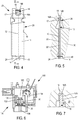
figure 5 représente le moule carapace vu en coupe longitudinale au travers du noyau; - La
figure 6 représente un exemple de four permettant la solidification dirigée de métal coulé dans un moule carapace ; - La
figure 7 est une vue agrandie de l'extrémité haute du moule carapace montré sur lafigure 5 .
- The
figure 1 represents a turbomachine blade obtainable according to the method of the invention; - The
figure 2 schematically shows a ceramic core for a turbine engine blade; - The
figure 3 represents the core of thefigure 2 seen in profile. - The
figure 4 schematically represents a wax model with the core of thefigure 2 ; - The
figure 5 represents the shell mold seen in longitudinal section through the core; - The
figure 6 shows an example of a furnace allowing the directed solidification of metal cast in a shell mold; - The
figure 7 is an enlarged view of the upper end of the shell mold shown on thefigure 5 .
La présente invention concerne un procédé de fabrication de pièces métalliques en alliage à base nickel permettant par une solidification dirigée appropriée d'obtenir une structure cristalline colonnaire ou monocristalline. L'invention vise plus particulièrement la fabrication d'aubes de turbomachine telle que celle représentée sur la
En raison de la complexité du circuit de refroidissement à l'intérieur de la pièce, il est avantageux de la réaliser par fonderie à la cire perdue avec un noyau en céramique pour ménager les cavités du circuit de refroidissement.
Les
Due to the complexity of the cooling circuit inside the part, it is advantageous to produce it by lost wax casting with a ceramic core to spare the cavities of the cooling circuit.
The
Ce noyau est placé dans un moule pour la fabrication du modèle en cire. L'empreinte de ce moule est à la forme de la pièce à obtenir. Par injection de cire dans ce moule, on obtient le modèle de la pièce. Les portées 14 et 16 servent au maintien du noyau dans le moule à cire. La
Plusieurs modèles sont généralement assemblés en grappe de manière à fabriquer plusieurs pièces simultanément. Les modèles sont par exemple disposés en tambour parallèlement autour d'un cylindre central vertical et maintenus par les extrémités. La partie inférieure est montée sur un élément destiné à assurer la germination de la structure cristalline. L'étape suivante consiste à constituer un moule carapace autour du ou des modèles. Dans ce but, comme cela est connu également, l'assemblage est trempé dans des barbotines de manière à déposer en couches successives les particules céramiques réfractaires. Le moule est enfin consolidé par chauffage et la cire éliminée par l'opération de décirage.Several models are generally assembled in a cluster so as to manufacture several parts simultaneously. The models are for example arranged in a parallel drum around a vertical central cylinder and held by the ends. The lower part is mounted on an element intended to ensure the germination of the crystal structure. The next step is to form a shell mold around the model (s). For this purpose, as is also known, the assembly is dipped in slurries so as to deposit the refractory ceramic particles in successive layers. The mold is finally consolidated by heating and the wax removed by the dewaxing operation.
On a représenté sur la
La première portée 14 est maintenue dans le moule 30 par une tige en céramique réfractaire 40, qui la traverse et s'étend dans la paroi du moule 30 en y étant encastrée. La tige 40 a été mise en place avant la réalisation du moule carapace, après que le modèle a été percé au niveau de la portée 14. Le perçage est de diamètre légèrement supérieur à celui de la tige de manière qu'il ne se crée pas de contraintes entre la tige et la portée et que la tige assure un positionnement correct du noyau dans le modèle.The
La seconde portée 16, opposée à la première, est initialement revêtue d'une couche de vernis 17 sur la partie 16A du noyau qui n'est pas recouverte de cire et qui après constitution du moule carapace vient au contact direct avec la paroi interne du moule. Après décirage du moule, comme on le voit sur la
Par ailleurs, les surfaces - ici la surface horizontale 16B - qui ne sont pas parallèles à l'axe de la progression de la solidification sont couvertes initialement par un dépôt de cire 18. Ce dépôt de cire laisse après décirage un espace libre, de même référence 18, qui évite à la portée 16 du noyau de venir en contact avec la paroi de la carapace lorsque le noyau se dilate, il évite ainsi la mise sous contrainte du noyau. Typiquement, l'épaisseur de ce dépôt de cire est de l'ordre du millimètre pour des pièces présentant une longueur de 100 à 200 mm soit environ 1% de la longueur de la pièce.Furthermore, the surfaces - here the
En n'étant pas contraint le noyau ne risque pas de flamber et les épaisseurs de paroi initiales de la pièce entre la paroi du moule et le noyau sont conservées.By not being constrained, the core does not run the risk of buckling and the initial wall thicknesses of the part between the wall of the mold and the core are preserved.
La
Après décirage et consolidation, le moule est placé sur la sole d'un four équipé pour la solidification dirigée. Un tel four 100 est représenté sur la
La méthode de fabrication, telle qu'expliquée dans le préambule de la demande, comprend la coulée du métal en fusion depuis le creuset 104 directement dans le moule 30 qui est maintenu à une température suffisante pour conserver le métal en fusion, par les moyens de chauffage 102 de l'enceinte 101 et où il vient remplir les vides 30' entre le noyau 10 et la paroi du moule 30. Comme la base du moule est en contact thermique avec la sole par l'élément de germination, le métal se solidifie en formant une structure cristalline que se propage de bas en haut. La sole 105 est refroidie en permanence et est descendue progressivement hors de l'enceinte chauffée. Dans le cas d'une structure monocristalline un sélecteur de grain est interposé entre la germination et la solidification comme cela est connu en soi.The manufacturing method, as explained in the preamble to the application, includes casting molten metal from
Les écarts de température importants créent des contraintes entre les différentes zones du moule avec le métal. Par l'agencement de l'invention et la tige 40, le noyau est maintenu par ancrage de la première portée 14 dans la seule zone inférieure d'initialisation de la solidification. Comme on le voit sur la
De plus, les surfaces de la seconde portée 16 - ici la surface horizontale 16B - qui ne sont pas parallèles à l'axe de la progression de la solidification, grâce à l'espace libre 18 ménagé par le dépôt de cire ne viennent pas en contact avec la paroi de la carapace. On évite ainsi la mise sous contrainte du noyau. Typiquement, l'épaisseur de cet espace correspondant au dépôt de cire est de l'ordre du millimètre pour des pièces présentant une longueur de 100 à 200 mm soit environ 1% de la longueur de la pièce. En n'étant pas contraint le noyau ne risque pas de flamber et les épaisseurs de paroi initiales de la pièce entre la paroi du moule et le noyau sont conservés.In addition, the surfaces of the second bearing 16 - here the
Une fois le métal refroidi, on casse le moule et on extrait les pièces qui sont dirigées vers l'atelier de finition.Once the metal has cooled, the mold is broken and the parts are extracted which are sent to the finishing workshop.
Claims (8)
- Method for manufacturing, using the lost-wax casting method, a metal component made from nickel alloy, with a columnar or monocrystalline structure with at least one elongate-shaped cavity, comprising the following steps of:producing a wax model (20) of the component with a ceramic core (10) corresponding to said cavity, the ceramic core (10) comprising a first holding span (14) at a longitudinal end and a second holding span (16) at the opposite end, the second span (16) comprising surfaces (16A) that are parallel to the direction of propagation of the cooling and surfaces (16B) that are not parallel to the direction of propagation of the cooling,producing a shell mould (30) around the model (20), the shell mould (30) comprising a base and the first span (14) of the core being on the same side as the base of the shell mould (30),eliminating the wax by dewaxing the shell mould (30),placing the shell mould (30) in a furnace (100), the base being placed on the hearth (105) of the furnace (100), pouring a molten alloy into the shell mould (30),carrying out a directed solidification of the poured metal by gradual cooling from the hearth (105) in a propagation direction, the surfaces (16B) of the second span (16) that are not parallel to the direction of propagation of the cooling being covered initially by a deposit of wax (18),characterized in that the core (10) is secured to the shell mould (30) by an anchor (40) between the first span (14) of the core and the wall of the shell mould (30), the second span (16) of the core (10) being held in the shell mould (30) by a holding means (17) sliding over the wall of the shell mould (30), said sliding holding means (17) comprising a layer of varnish (17) applied, before the production of the shell mould (30), to the surfaces (16A) of the second span (16) that are parallel to the direction of propagation of the cooling and that are not covered with wax, the surfaces (16A) of the second span (16) that are parallel to the direction of propagation of the cooling and that are not covered with wax and that, after formation of the shell mould (30), comes into direct contact with the internal wall of the mould (30), being initially fully covered with said layer of varnish (17), the layer of varnish (17) having a thickness of between 3 and 5 hundredths of a millimetre, said layer of varnish (17) being eliminated during the operation of dewaxing the shell mould (30), as well as the wax (18) covering the surfaces (16B) of the second span (16) that are not parallel to the direction of propagation of the cooling, so that a free space (17, 18) is created between the second span (16) of the core (10) and the wall of the shell mould (30),said free space (17, 18) created being maintained during the progression of the directed solidification, so as to prevent the second span (16) of the core (10) from coming into contact with the wall of the shell mould (30) when the core (10) expands.
- Method according to claim 1, wherein the anchoring means (40) comprises a rod passing through the first span (14) and being embedded in the wall of the mould.
- Method according to claim 2, wherein the rod is made from ceramic.
- Method according to one of the preceding claims, for manufacturing a plurality of components, the models of said components being collected together in a cluster inside a shell mould (30).
- Method according to one of the preceding claims, for manufacturing at least one metal component with a columnar structure, an element for nucleation of the crystalline structure being provided between the shell mould (30) and the hearth (105) of the furnace (100).
- Method according to the preceding claim, for manufacturing at least one component with a monocrystalline structure, comprising a grain selector between the nucleation element and the shell mould (30).
- Method according to one of the preceding claims, the component being a turbine engine blade, the first span being in the extension of the apex of the vane of the blade, the second span being in the extension of the root of the blade.
- Method according to one of the preceding claims, wherein the hearth is able to move vertically between a hot region where the metal is molten and a cold region for solidification of the metal, the hearth itself being cooled.
Applications Claiming Priority (2)
| Application Number | Priority Date | Filing Date | Title |
|---|---|---|---|
| FR1350424A FR3000910B1 (en) | 2013-01-17 | 2013-01-17 | PROCESS FOR MANUFACTURING A PIECE BY LOST WAX FOUNDRY AND DIRECTED COOLING |
| PCT/FR2014/050061 WO2014111648A1 (en) | 2013-01-17 | 2014-01-13 | Method for manufacturing a component using the lost‑wax casting method with directed cooling |
Publications (2)
| Publication Number | Publication Date |
|---|---|
| EP2945762A1 EP2945762A1 (en) | 2015-11-25 |
| EP2945762B1 true EP2945762B1 (en) | 2021-03-03 |
Family
ID=48289291
Family Applications (1)
| Application Number | Title | Priority Date | Filing Date |
|---|---|---|---|
| EP14703143.9A Active EP2945762B1 (en) | 2013-01-17 | 2014-01-13 | Method for manufacturing a component using the lost wax casting method with directed cooling |
Country Status (9)
| Country | Link |
|---|---|
| US (1) | US10717128B2 (en) |
| EP (1) | EP2945762B1 (en) |
| JP (1) | JP6342427B2 (en) |
| CN (1) | CN104918731B (en) |
| BR (1) | BR112015016771B1 (en) |
| CA (1) | CA2897680C (en) |
| FR (1) | FR3000910B1 (en) |
| RU (1) | RU2652526C2 (en) |
| WO (1) | WO2014111648A1 (en) |
Families Citing this family (9)
| Publication number | Priority date | Publication date | Assignee | Title |
|---|---|---|---|---|
| FR3034332A1 (en) * | 2015-04-01 | 2016-10-07 | Saint Jean Ind | PROCESS FOR SANDING CARAPLE MOLDING FOR THE PRODUCTION OF A PART IN THE AUTOMOTIVE AND AERONAUTICS FIELD |
| FR3067700B1 (en) | 2017-06-18 | 2021-02-12 | Sogeclair Sa | METAL STRUCTURE WITH REINFORCED SKIN AND PROCESS FOR MANUFACTURING A STRIPED METAL PART |
| FR3070285B1 (en) * | 2017-08-25 | 2021-01-22 | Safran Aircraft Engines | CORE FOR MAKING A TURBOMACHINE VANE |
| CN109570444A (en) * | 2018-09-30 | 2019-04-05 | 鹰普航空零部件(无锡)有限公司 | A kind of manufacturing process of complex-shaped surface mould stainless cast steel part |
| CN109622883B (en) * | 2019-01-08 | 2021-07-23 | 中国航发动力股份有限公司 | Manufacturing method of ceramic core free end wax cap |
| FR3100143B1 (en) * | 2019-08-30 | 2021-11-12 | Safran | Improved method of manufacturing a ceramic core for the manufacture of turbine engine blades |
| CN115069978A (en) * | 2021-03-16 | 2022-09-20 | 中国航发商用航空发动机有限责任公司 | Casting system and casting method for splash plate of combustion chamber |
| CN113976824B (en) * | 2021-10-20 | 2023-09-15 | 中国航发沈阳黎明航空发动机有限责任公司 | Method for preventing mixed crystals from being generated at free end of conjuncted single crystal guide blade core |
| CN115121768B (en) * | 2022-04-26 | 2024-04-05 | 湘潭大学 | Shell structure, preparation method thereof and hot cracking tendency judging method |
Citations (2)
| Publication number | Priority date | Publication date | Assignee | Title |
|---|---|---|---|---|
| US3659645A (en) * | 1965-08-09 | 1972-05-02 | Trw Inc | Means for supporting core in open ended shell mold |
| US6364001B1 (en) * | 2000-08-15 | 2002-04-02 | Pcc Airfoils, Inc. | Method of casting an article |
Family Cites Families (15)
| Publication number | Priority date | Publication date | Assignee | Title |
|---|---|---|---|---|
| US2756475A (en) * | 1953-02-24 | 1956-07-31 | Gen Motors Corp | Investment mold and core assembly |
| US3722577A (en) * | 1971-04-20 | 1973-03-27 | Mellen E | Expansible shell mold with refractory slip cover and the method of making same |
| DE2301105C2 (en) * | 1973-01-10 | 1984-07-05 | Sherwood Refractories Inc., Cleveland, Ohio | Precision mold and method of making it |
| SU606676A1 (en) * | 1976-12-13 | 1978-05-15 | Пермский Моторостроительный Завод Имени Я.М.Свердлова | Investment casting mould |
| FR2724857B1 (en) * | 1980-12-30 | 1997-01-03 | Snecma | PROCESS FOR THE MANUFACTURE OF CRYSTALLINE BLADES |
| US4714101A (en) * | 1981-04-02 | 1987-12-22 | United Technologies Corporation | Method and apparatus for epitaxial solidification |
| US4532974A (en) * | 1981-07-03 | 1985-08-06 | Rolls-Royce Limited | Component casting |
| JPH05138296A (en) * | 1991-11-22 | 1993-06-01 | Toshiba Corp | Mold for manufacturing hollow casting |
| US20050211408A1 (en) * | 2004-03-25 | 2005-09-29 | Bullied Steven J | Single crystal investment cast components and methods of making same |
| FR2889088B1 (en) * | 2005-07-29 | 2008-08-22 | Snecma | CORE FOR BLADE OF TURBOMACHINE |
| US7231955B1 (en) * | 2006-01-30 | 2007-06-19 | United Technologies Corporation | Investment casting mold design and method for investment casting using the same |
| CN100584973C (en) * | 2007-12-17 | 2010-01-27 | 北京航空航天大学 | Method for preparing Co based single-crystal refractory alloy by employing combination of seed crystal method and screw selecting method |
| CN101537485B (en) * | 2009-03-17 | 2013-01-23 | 江苏大学 | Thin shell floating method for manufacturing single crystal casting and device thereof |
| CN102019354B (en) * | 2010-12-27 | 2012-11-07 | 沈阳黎明航空发动机(集团)有限责任公司 | Directional solidification method of ultra-thin and long shrouded blade |
| CN102169518A (en) | 2011-03-24 | 2011-08-31 | 西北工业大学 | Accurate forming method for precise-casting turbine blade die cavity |
-
2013
- 2013-01-17 FR FR1350424A patent/FR3000910B1/en active Active
-
2014
- 2014-01-13 BR BR112015016771A patent/BR112015016771B1/en active IP Right Grant
- 2014-01-13 CN CN201480004729.4A patent/CN104918731B/en active Active
- 2014-01-13 US US14/760,559 patent/US10717128B2/en active Active
- 2014-01-13 JP JP2015553146A patent/JP6342427B2/en active Active
- 2014-01-13 WO PCT/FR2014/050061 patent/WO2014111648A1/en active Application Filing
- 2014-01-13 EP EP14703143.9A patent/EP2945762B1/en active Active
- 2014-01-13 CA CA2897680A patent/CA2897680C/en active Active
- 2014-01-13 RU RU2015128268A patent/RU2652526C2/en active
Patent Citations (2)
| Publication number | Priority date | Publication date | Assignee | Title |
|---|---|---|---|---|
| US3659645A (en) * | 1965-08-09 | 1972-05-02 | Trw Inc | Means for supporting core in open ended shell mold |
| US6364001B1 (en) * | 2000-08-15 | 2002-04-02 | Pcc Airfoils, Inc. | Method of casting an article |
Also Published As
| Publication number | Publication date |
|---|---|
| US20150352634A1 (en) | 2015-12-10 |
| US10717128B2 (en) | 2020-07-21 |
| CN104918731B (en) | 2019-12-27 |
| RU2652526C2 (en) | 2018-04-26 |
| EP2945762A1 (en) | 2015-11-25 |
| CA2897680C (en) | 2021-03-23 |
| BR112015016771A2 (en) | 2017-07-11 |
| CA2897680A1 (en) | 2014-07-24 |
| JP6342427B2 (en) | 2018-06-13 |
| CN104918731A (en) | 2015-09-16 |
| RU2015128268A (en) | 2017-02-21 |
| FR3000910A1 (en) | 2014-07-18 |
| WO2014111648A1 (en) | 2014-07-24 |
| JP2016503729A (en) | 2016-02-08 |
| FR3000910B1 (en) | 2015-05-01 |
| BR112015016771B1 (en) | 2020-01-28 |
Similar Documents
| Publication | Publication Date | Title |
|---|---|---|
| EP2945762B1 (en) | Method for manufacturing a component using the lost wax casting method with directed cooling | |
| CA2885896C (en) | Shell mould having a heat shield | |
| EP2092999B1 (en) | Method of manufacturing vanes with directional solidification | |
| CA2909031C (en) | Monocrystalline smelting mould | |
| CA2884458C (en) | Foundry model | |
| EP3134219B1 (en) | Mould for monocrystalline casting | |
| FR3033721A1 (en) | FLEXIBLE THERMAL SCREEN MOLD | |
| FR2874340A1 (en) | Foundry method for fabricating jet engine blade, involves manufacturing shell whose additional part is arranged on another part, where additional part is plane and perpendicular to vertical axis of latter part | |
| EP3645191B1 (en) | Foundry process with hot mold casting | |
| CA3029438C (en) | Directional solidification cooling furnace and cooling process using such a furnace | |
| EP4061557B1 (en) | Foundry mold, method for manufacturing the mold and foundry method | |
| WO2020240108A1 (en) | Method for producing a single-crystal metal turbine blade |
Legal Events
| Date | Code | Title | Description |
|---|---|---|---|
| PUAI | Public reference made under article 153(3) epc to a published international application that has entered the european phase |
Free format text: ORIGINAL CODE: 0009012 |
|
| 17P | Request for examination filed |
Effective date: 20150722 |
|
| AK | Designated contracting states |
Kind code of ref document: A1 Designated state(s): AL AT BE BG CH CY CZ DE DK EE ES FI FR GB GR HR HU IE IS IT LI LT LU LV MC MK MT NL NO PL PT RO RS SE SI SK SM TR |
|
| AX | Request for extension of the european patent |
Extension state: BA ME |
|
| RAP1 | Party data changed (applicant data changed or rights of an application transferred) |
Owner name: SNECMA |
|
| DAX | Request for extension of the european patent (deleted) | ||
| RAP1 | Party data changed (applicant data changed or rights of an application transferred) |
Owner name: SAFRAN AIRCRAFT ENGINES |
|
| STAA | Information on the status of an ep patent application or granted ep patent |
Free format text: STATUS: EXAMINATION IS IN PROGRESS |
|
| 17Q | First examination report despatched |
Effective date: 20180212 |
|
| GRAP | Despatch of communication of intention to grant a patent |
Free format text: ORIGINAL CODE: EPIDOSNIGR1 |
|
| STAA | Information on the status of an ep patent application or granted ep patent |
Free format text: STATUS: GRANT OF PATENT IS INTENDED |
|
| INTG | Intention to grant announced |
Effective date: 20200824 |
|
| GRAS | Grant fee paid |
Free format text: ORIGINAL CODE: EPIDOSNIGR3 |
|
| STAA | Information on the status of an ep patent application or granted ep patent |
Free format text: STATUS: GRANT OF PATENT IS INTENDED |
|
| GRAA | (expected) grant |
Free format text: ORIGINAL CODE: 0009210 |
|
| STAA | Information on the status of an ep patent application or granted ep patent |
Free format text: STATUS: THE PATENT HAS BEEN GRANTED |
|
| AK | Designated contracting states |
Kind code of ref document: B1 Designated state(s): AL AT BE BG CH CY CZ DE DK EE ES FI FR GB GR HR HU IE IS IT LI LT LU LV MC MK MT NL NO PL PT RO RS SE SI SK SM TR |
|
| REG | Reference to a national code |
Ref country code: GB Ref legal event code: FG4D Free format text: NOT ENGLISH |
|
| REG | Reference to a national code |
Ref country code: AT Ref legal event code: REF Ref document number: 1366656 Country of ref document: AT Kind code of ref document: T Effective date: 20210315 Ref country code: CH Ref legal event code: EP |
|
| REG | Reference to a national code |
Ref country code: DE Ref legal event code: R096 Ref document number: 602014075327 Country of ref document: DE |
|
| REG | Reference to a national code |
Ref country code: IE Ref legal event code: FG4D Free format text: LANGUAGE OF EP DOCUMENT: FRENCH |
|
| REG | Reference to a national code |
Ref country code: SE Ref legal event code: TRGR |
|
| REG | Reference to a national code |
Ref country code: LT Ref legal event code: MG9D |
|
| PG25 | Lapsed in a contracting state [announced via postgrant information from national office to epo] |
Ref country code: HR Free format text: LAPSE BECAUSE OF FAILURE TO SUBMIT A TRANSLATION OF THE DESCRIPTION OR TO PAY THE FEE WITHIN THE PRESCRIBED TIME-LIMIT Effective date: 20210303 Ref country code: FI Free format text: LAPSE BECAUSE OF FAILURE TO SUBMIT A TRANSLATION OF THE DESCRIPTION OR TO PAY THE FEE WITHIN THE PRESCRIBED TIME-LIMIT Effective date: 20210303 Ref country code: GR Free format text: LAPSE BECAUSE OF FAILURE TO SUBMIT A TRANSLATION OF THE DESCRIPTION OR TO PAY THE FEE WITHIN THE PRESCRIBED TIME-LIMIT Effective date: 20210604 Ref country code: LT Free format text: LAPSE BECAUSE OF FAILURE TO SUBMIT A TRANSLATION OF THE DESCRIPTION OR TO PAY THE FEE WITHIN THE PRESCRIBED TIME-LIMIT Effective date: 20210303 Ref country code: BG Free format text: LAPSE BECAUSE OF FAILURE TO SUBMIT A TRANSLATION OF THE DESCRIPTION OR TO PAY THE FEE WITHIN THE PRESCRIBED TIME-LIMIT Effective date: 20210603 Ref country code: NO Free format text: LAPSE BECAUSE OF FAILURE TO SUBMIT A TRANSLATION OF THE DESCRIPTION OR TO PAY THE FEE WITHIN THE PRESCRIBED TIME-LIMIT Effective date: 20210603 |
|
| REG | Reference to a national code |
Ref country code: NL Ref legal event code: MP Effective date: 20210303 |
|
| REG | Reference to a national code |
Ref country code: AT Ref legal event code: MK05 Ref document number: 1366656 Country of ref document: AT Kind code of ref document: T Effective date: 20210303 |
|
| PG25 | Lapsed in a contracting state [announced via postgrant information from national office to epo] |
Ref country code: PL Free format text: LAPSE BECAUSE OF FAILURE TO SUBMIT A TRANSLATION OF THE DESCRIPTION OR TO PAY THE FEE WITHIN THE PRESCRIBED TIME-LIMIT Effective date: 20210303 Ref country code: LV Free format text: LAPSE BECAUSE OF FAILURE TO SUBMIT A TRANSLATION OF THE DESCRIPTION OR TO PAY THE FEE WITHIN THE PRESCRIBED TIME-LIMIT Effective date: 20210303 Ref country code: RS Free format text: LAPSE BECAUSE OF FAILURE TO SUBMIT A TRANSLATION OF THE DESCRIPTION OR TO PAY THE FEE WITHIN THE PRESCRIBED TIME-LIMIT Effective date: 20210303 |
|
| PG25 | Lapsed in a contracting state [announced via postgrant information from national office to epo] |
Ref country code: NL Free format text: LAPSE BECAUSE OF FAILURE TO SUBMIT A TRANSLATION OF THE DESCRIPTION OR TO PAY THE FEE WITHIN THE PRESCRIBED TIME-LIMIT Effective date: 20210303 |
|
| PG25 | Lapsed in a contracting state [announced via postgrant information from national office to epo] |
Ref country code: SM Free format text: LAPSE BECAUSE OF FAILURE TO SUBMIT A TRANSLATION OF THE DESCRIPTION OR TO PAY THE FEE WITHIN THE PRESCRIBED TIME-LIMIT Effective date: 20210303 Ref country code: AT Free format text: LAPSE BECAUSE OF FAILURE TO SUBMIT A TRANSLATION OF THE DESCRIPTION OR TO PAY THE FEE WITHIN THE PRESCRIBED TIME-LIMIT Effective date: 20210303 Ref country code: EE Free format text: LAPSE BECAUSE OF FAILURE TO SUBMIT A TRANSLATION OF THE DESCRIPTION OR TO PAY THE FEE WITHIN THE PRESCRIBED TIME-LIMIT Effective date: 20210303 Ref country code: CZ Free format text: LAPSE BECAUSE OF FAILURE TO SUBMIT A TRANSLATION OF THE DESCRIPTION OR TO PAY THE FEE WITHIN THE PRESCRIBED TIME-LIMIT Effective date: 20210303 |
|
| PG25 | Lapsed in a contracting state [announced via postgrant information from national office to epo] |
Ref country code: SK Free format text: LAPSE BECAUSE OF FAILURE TO SUBMIT A TRANSLATION OF THE DESCRIPTION OR TO PAY THE FEE WITHIN THE PRESCRIBED TIME-LIMIT Effective date: 20210303 Ref country code: RO Free format text: LAPSE BECAUSE OF FAILURE TO SUBMIT A TRANSLATION OF THE DESCRIPTION OR TO PAY THE FEE WITHIN THE PRESCRIBED TIME-LIMIT Effective date: 20210303 Ref country code: PT Free format text: LAPSE BECAUSE OF FAILURE TO SUBMIT A TRANSLATION OF THE DESCRIPTION OR TO PAY THE FEE WITHIN THE PRESCRIBED TIME-LIMIT Effective date: 20210705 Ref country code: ES Free format text: LAPSE BECAUSE OF FAILURE TO SUBMIT A TRANSLATION OF THE DESCRIPTION OR TO PAY THE FEE WITHIN THE PRESCRIBED TIME-LIMIT Effective date: 20210303 Ref country code: IS Free format text: LAPSE BECAUSE OF FAILURE TO SUBMIT A TRANSLATION OF THE DESCRIPTION OR TO PAY THE FEE WITHIN THE PRESCRIBED TIME-LIMIT Effective date: 20210703 |
|
| REG | Reference to a national code |
Ref country code: DE Ref legal event code: R097 Ref document number: 602014075327 Country of ref document: DE |
|
| PLBE | No opposition filed within time limit |
Free format text: ORIGINAL CODE: 0009261 |
|
| STAA | Information on the status of an ep patent application or granted ep patent |
Free format text: STATUS: NO OPPOSITION FILED WITHIN TIME LIMIT |
|
| PG25 | Lapsed in a contracting state [announced via postgrant information from national office to epo] |
Ref country code: DK Free format text: LAPSE BECAUSE OF FAILURE TO SUBMIT A TRANSLATION OF THE DESCRIPTION OR TO PAY THE FEE WITHIN THE PRESCRIBED TIME-LIMIT Effective date: 20210303 Ref country code: AL Free format text: LAPSE BECAUSE OF FAILURE TO SUBMIT A TRANSLATION OF THE DESCRIPTION OR TO PAY THE FEE WITHIN THE PRESCRIBED TIME-LIMIT Effective date: 20210303 |
|
| 26N | No opposition filed |
Effective date: 20211206 |
|
| PG25 | Lapsed in a contracting state [announced via postgrant information from national office to epo] |
Ref country code: SI Free format text: LAPSE BECAUSE OF FAILURE TO SUBMIT A TRANSLATION OF THE DESCRIPTION OR TO PAY THE FEE WITHIN THE PRESCRIBED TIME-LIMIT Effective date: 20210303 |
|
| PG25 | Lapsed in a contracting state [announced via postgrant information from national office to epo] |
Ref country code: IS Free format text: LAPSE BECAUSE OF FAILURE TO SUBMIT A TRANSLATION OF THE DESCRIPTION OR TO PAY THE FEE WITHIN THE PRESCRIBED TIME-LIMIT Effective date: 20210703 |
|
| PG25 | Lapsed in a contracting state [announced via postgrant information from national office to epo] |
Ref country code: MC Free format text: LAPSE BECAUSE OF FAILURE TO SUBMIT A TRANSLATION OF THE DESCRIPTION OR TO PAY THE FEE WITHIN THE PRESCRIBED TIME-LIMIT Effective date: 20210303 |
|
| REG | Reference to a national code |
Ref country code: CH Ref legal event code: PL |
|
| REG | Reference to a national code |
Ref country code: BE Ref legal event code: MM Effective date: 20220131 |
|
| PG25 | Lapsed in a contracting state [announced via postgrant information from national office to epo] |
Ref country code: LU Free format text: LAPSE BECAUSE OF NON-PAYMENT OF DUE FEES Effective date: 20220113 |
|
| PG25 | Lapsed in a contracting state [announced via postgrant information from national office to epo] |
Ref country code: BE Free format text: LAPSE BECAUSE OF NON-PAYMENT OF DUE FEES Effective date: 20220131 |
|
| PG25 | Lapsed in a contracting state [announced via postgrant information from national office to epo] |
Ref country code: LI Free format text: LAPSE BECAUSE OF NON-PAYMENT OF DUE FEES Effective date: 20220131 Ref country code: CH Free format text: LAPSE BECAUSE OF NON-PAYMENT OF DUE FEES Effective date: 20220131 |
|
| PG25 | Lapsed in a contracting state [announced via postgrant information from national office to epo] |
Ref country code: IE Free format text: LAPSE BECAUSE OF NON-PAYMENT OF DUE FEES Effective date: 20220113 |
|
| PGFP | Annual fee paid to national office [announced via postgrant information from national office to epo] |
Ref country code: IT Payment date: 20230103 Year of fee payment: 10 Ref country code: DE Payment date: 20221220 Year of fee payment: 10 |
|
| PGFP | Annual fee paid to national office [announced via postgrant information from national office to epo] |
Ref country code: GB Payment date: 20231219 Year of fee payment: 11 |
|
| PGFP | Annual fee paid to national office [announced via postgrant information from national office to epo] |
Ref country code: SE Payment date: 20231219 Year of fee payment: 11 Ref country code: FR Payment date: 20231219 Year of fee payment: 11 |
|
| PG25 | Lapsed in a contracting state [announced via postgrant information from national office to epo] |
Ref country code: HU Free format text: LAPSE BECAUSE OF FAILURE TO SUBMIT A TRANSLATION OF THE DESCRIPTION OR TO PAY THE FEE WITHIN THE PRESCRIBED TIME-LIMIT; INVALID AB INITIO Effective date: 20140113 |