EP2945682B2 - Infusion catheter with guidewire valving - Google Patents
Infusion catheter with guidewire valving Download PDFInfo
- Publication number
- EP2945682B2 EP2945682B2 EP14703651.1A EP14703651A EP2945682B2 EP 2945682 B2 EP2945682 B2 EP 2945682B2 EP 14703651 A EP14703651 A EP 14703651A EP 2945682 B2 EP2945682 B2 EP 2945682B2
- Authority
- EP
- European Patent Office
- Prior art keywords
- guidewire
- infusion
- distal
- proximal
- optionally
- Prior art date
- Legal status (The legal status is an assumption and is not a legal conclusion. Google has not performed a legal analysis and makes no representation as to the accuracy of the status listed.)
- Active
Links
Images


Classifications
-
- A—HUMAN NECESSITIES
- A61—MEDICAL OR VETERINARY SCIENCE; HYGIENE
- A61M—DEVICES FOR INTRODUCING MEDIA INTO, OR ONTO, THE BODY; DEVICES FOR TRANSDUCING BODY MEDIA OR FOR TAKING MEDIA FROM THE BODY; DEVICES FOR PRODUCING OR ENDING SLEEP OR STUPOR
- A61M5/00—Devices for bringing media into the body in a subcutaneous, intra-vascular or intramuscular way; Accessories therefor, e.g. filling or cleaning devices, arm-rests
- A61M5/14—Infusion devices, e.g. infusing by gravity; Blood infusion; Accessories therefor
-
- A—HUMAN NECESSITIES
- A61—MEDICAL OR VETERINARY SCIENCE; HYGIENE
- A61M—DEVICES FOR INTRODUCING MEDIA INTO, OR ONTO, THE BODY; DEVICES FOR TRANSDUCING BODY MEDIA OR FOR TAKING MEDIA FROM THE BODY; DEVICES FOR PRODUCING OR ENDING SLEEP OR STUPOR
- A61M25/00—Catheters; Hollow probes
- A61M25/0021—Catheters; Hollow probes characterised by the form of the tubing
- A61M25/0023—Catheters; Hollow probes characterised by the form of the tubing by the form of the lumen, e.g. cross-section, variable diameter
- A61M25/0026—Multi-lumen catheters with stationary elements
- A61M25/003—Multi-lumen catheters with stationary elements characterized by features relating to least one lumen located at the distal part of the catheter, e.g. filters, plugs or valves
-
- A—HUMAN NECESSITIES
- A61—MEDICAL OR VETERINARY SCIENCE; HYGIENE
- A61M—DEVICES FOR INTRODUCING MEDIA INTO, OR ONTO, THE BODY; DEVICES FOR TRANSDUCING BODY MEDIA OR FOR TAKING MEDIA FROM THE BODY; DEVICES FOR PRODUCING OR ENDING SLEEP OR STUPOR
- A61M25/00—Catheters; Hollow probes
- A61M25/0043—Catheters; Hollow probes characterised by structural features
- A61M25/005—Catheters; Hollow probes characterised by structural features with embedded materials for reinforcement, e.g. wires, coils, braids
- A61M25/0052—Localized reinforcement, e.g. where only a specific part of the catheter is reinforced, for rapid exchange guidewire port
-
- A—HUMAN NECESSITIES
- A61—MEDICAL OR VETERINARY SCIENCE; HYGIENE
- A61M—DEVICES FOR INTRODUCING MEDIA INTO, OR ONTO, THE BODY; DEVICES FOR TRANSDUCING BODY MEDIA OR FOR TAKING MEDIA FROM THE BODY; DEVICES FOR PRODUCING OR ENDING SLEEP OR STUPOR
- A61M25/00—Catheters; Hollow probes
- A61M25/0067—Catheters; Hollow probes characterised by the distal end, e.g. tips
- A61M25/0074—Dynamic characteristics of the catheter tip, e.g. openable, closable, expandable or deformable
- A61M25/0075—Valve means
-
- A—HUMAN NECESSITIES
- A61—MEDICAL OR VETERINARY SCIENCE; HYGIENE
- A61M—DEVICES FOR INTRODUCING MEDIA INTO, OR ONTO, THE BODY; DEVICES FOR TRANSDUCING BODY MEDIA OR FOR TAKING MEDIA FROM THE BODY; DEVICES FOR PRODUCING OR ENDING SLEEP OR STUPOR
- A61M25/00—Catheters; Hollow probes
- A61M25/0067—Catheters; Hollow probes characterised by the distal end, e.g. tips
- A61M25/008—Strength or flexibility characteristics of the catheter tip
-
- A—HUMAN NECESSITIES
- A61—MEDICAL OR VETERINARY SCIENCE; HYGIENE
- A61M—DEVICES FOR INTRODUCING MEDIA INTO, OR ONTO, THE BODY; DEVICES FOR TRANSDUCING BODY MEDIA OR FOR TAKING MEDIA FROM THE BODY; DEVICES FOR PRODUCING OR ENDING SLEEP OR STUPOR
- A61M25/00—Catheters; Hollow probes
- A61M25/01—Introducing, guiding, advancing, emplacing or holding catheters
- A61M25/09—Guide wires
- A61M25/09041—Mechanisms for insertion of guide wires
-
- A—HUMAN NECESSITIES
- A61—MEDICAL OR VETERINARY SCIENCE; HYGIENE
- A61M—DEVICES FOR INTRODUCING MEDIA INTO, OR ONTO, THE BODY; DEVICES FOR TRANSDUCING BODY MEDIA OR FOR TAKING MEDIA FROM THE BODY; DEVICES FOR PRODUCING OR ENDING SLEEP OR STUPOR
- A61M25/00—Catheters; Hollow probes
- A61M25/10—Balloon catheters
- A61M25/104—Balloon catheters used for angioplasty
-
- A—HUMAN NECESSITIES
- A61—MEDICAL OR VETERINARY SCIENCE; HYGIENE
- A61M—DEVICES FOR INTRODUCING MEDIA INTO, OR ONTO, THE BODY; DEVICES FOR TRANSDUCING BODY MEDIA OR FOR TAKING MEDIA FROM THE BODY; DEVICES FOR PRODUCING OR ENDING SLEEP OR STUPOR
- A61M25/00—Catheters; Hollow probes
- A61M2025/0018—Catheters; Hollow probes having a plug, e.g. an inflatable plug for closing catheter lumens
-
- A—HUMAN NECESSITIES
- A61—MEDICAL OR VETERINARY SCIENCE; HYGIENE
- A61M—DEVICES FOR INTRODUCING MEDIA INTO, OR ONTO, THE BODY; DEVICES FOR TRANSDUCING BODY MEDIA OR FOR TAKING MEDIA FROM THE BODY; DEVICES FOR PRODUCING OR ENDING SLEEP OR STUPOR
- A61M25/00—Catheters; Hollow probes
- A61M25/0067—Catheters; Hollow probes characterised by the distal end, e.g. tips
- A61M25/0074—Dynamic characteristics of the catheter tip, e.g. openable, closable, expandable or deformable
- A61M25/0075—Valve means
- A61M2025/0076—Unidirectional valves
-
- A—HUMAN NECESSITIES
- A61—MEDICAL OR VETERINARY SCIENCE; HYGIENE
- A61M—DEVICES FOR INTRODUCING MEDIA INTO, OR ONTO, THE BODY; DEVICES FOR TRANSDUCING BODY MEDIA OR FOR TAKING MEDIA FROM THE BODY; DEVICES FOR PRODUCING OR ENDING SLEEP OR STUPOR
- A61M25/00—Catheters; Hollow probes
- A61M25/0067—Catheters; Hollow probes characterised by the distal end, e.g. tips
- A61M25/0074—Dynamic characteristics of the catheter tip, e.g. openable, closable, expandable or deformable
- A61M2025/0079—Separate user-activated means, e.g. guidewires, guide tubes, balloon catheters or sheaths, for sealing off an orifice, e.g. a lumen or side holes, of a catheter
-
- A—HUMAN NECESSITIES
- A61—MEDICAL OR VETERINARY SCIENCE; HYGIENE
- A61M—DEVICES FOR INTRODUCING MEDIA INTO, OR ONTO, THE BODY; DEVICES FOR TRANSDUCING BODY MEDIA OR FOR TAKING MEDIA FROM THE BODY; DEVICES FOR PRODUCING OR ENDING SLEEP OR STUPOR
- A61M25/00—Catheters; Hollow probes
- A61M25/0067—Catheters; Hollow probes characterised by the distal end, e.g. tips
- A61M25/008—Strength or flexibility characteristics of the catheter tip
- A61M2025/0081—Soft tip
-
- A—HUMAN NECESSITIES
- A61—MEDICAL OR VETERINARY SCIENCE; HYGIENE
- A61M—DEVICES FOR INTRODUCING MEDIA INTO, OR ONTO, THE BODY; DEVICES FOR TRANSDUCING BODY MEDIA OR FOR TAKING MEDIA FROM THE BODY; DEVICES FOR PRODUCING OR ENDING SLEEP OR STUPOR
- A61M25/00—Catheters; Hollow probes
- A61M25/01—Introducing, guiding, advancing, emplacing or holding catheters
- A61M25/09—Guide wires
- A61M2025/091—Guide wires having a lumen for drug delivery or suction
-
- A—HUMAN NECESSITIES
- A61—MEDICAL OR VETERINARY SCIENCE; HYGIENE
- A61M—DEVICES FOR INTRODUCING MEDIA INTO, OR ONTO, THE BODY; DEVICES FOR TRANSDUCING BODY MEDIA OR FOR TAKING MEDIA FROM THE BODY; DEVICES FOR PRODUCING OR ENDING SLEEP OR STUPOR
- A61M25/00—Catheters; Hollow probes
- A61M25/10—Balloon catheters
- A61M2025/1043—Balloon catheters with special features or adapted for special applications
- A61M2025/1052—Balloon catheters with special features or adapted for special applications for temporarily occluding a vessel for isolating a sector
-
- A—HUMAN NECESSITIES
- A61—MEDICAL OR VETERINARY SCIENCE; HYGIENE
- A61M—DEVICES FOR INTRODUCING MEDIA INTO, OR ONTO, THE BODY; DEVICES FOR TRANSDUCING BODY MEDIA OR FOR TAKING MEDIA FROM THE BODY; DEVICES FOR PRODUCING OR ENDING SLEEP OR STUPOR
- A61M2210/00—Anatomical parts of the body
- A61M2210/12—Blood circulatory system
Definitions
- the present invention in some embodiments thereof, relates to medical devices, and in particular to balloon catheters applicable for treating blood vessels.
- Balloon catheters are well known and used in treating various conditions in blood vessels.
- Two main types of balloon catheters in that area are dilatation balloon catheter, used to treat narrowed or stenotic portions of the vessel and recover flow (e.g., angioplasty balloon catheters), and occlusion balloon catheters, used to temporarily block flow out of a vessel segment while infusing fluid (e.g., medicament, contrast enhancer or flushing material) therein.
- dilatation balloon catheter used to treat narrowed or stenotic portions of the vessel and recover flow
- occlusion balloon catheters used to temporarily block flow out of a vessel segment while infusing fluid (e.g., medicament, contrast enhancer or flushing material) therein.
- Some balloon catheters have at least three parallel functions, including: balloon inflation, travel over a guide wire, and infusion or dispersion of fluids therethrough. Such balloon catheters often include at least three lumens passing there along, including an inflation lumen, a guidewire lumen and an infusion lumen, correspondingly.
- a balloon catheter comprising an infusion exit opening located proximally to the balloon member, particularly if the balloon member is used for occlusion at least partially during infusion.
- US 7,182,755 describes a use of an occlusion balloon catheter with a proximal infusion opening for treating hemodialysis vascular access.
- US 5,368,567 describes a dilatation balloon catheter with a proximal infusion opening.
- minimization of catheter's lumens cross-sections is advantageous.
- a small diameter catheter for intraluminal passage e.g., 3F to 5F
- intraluminal passage e.g. 3F to 5F
- a catheter for medical applications suitable for being inserted into a duct comprising a first vessel and a second vessel which branches off from the first vessel.
- the catheter comprises a catheter body which extends from a proximal end to a distal end, a main cavity, which connects the proximal end to the distal end, and at least one opening, disposed at the distal end and suitable for perfusing a substance from the main cavity to the second vessel.
- the catheter at the distal end, comprises first and second occluding means suitable for at least partially occluding the distal end so as to infuse the second vessel indirectly, creating a preferred flow of substance from the at least one opening to the second vessel.”
- a catheter for retroprofusing a venous junction formed by first, second and third veins includes an elongate tube having a plurality of channels including a through-lumen extending between a proximal end and a distal end.
- a proximal balloon is inflatable to partially occlude the third vein, while a distal balloon is inflatable to partially occlude the second vein.
- An operative region of the catheter between the first and second balloons is adapted to pressurize the venous junction with arterial blood to produce retrograde blood flow in the first vein.
- the emboli protection system provides one or more inflatable blocking balloons for isolation of a section of a blood vessel to prevent migration of emboli from the section during an interventional procedure, and fluid infusion and evacuation ports for flushing emboli from the isolated section.
- One embodiment provides for a distal blocking balloon catheter, over which an interventional device can be introduced, and a proximal blocking balloon catheter to be introduced over the interventional device for isolating a portion of a blood vessel to be treated.
- the blocking balloons can be perforated to provide the infusion ports, and thrombolytic inflation fluid may be used to break down and dissolve thrombus and plaque in the isolated portion of the blood vessel.
- the interventional therapeutic device such as an angioplasty balloon catheter may be incorporated into the distal blocking balloon catheter, or the distal and blocking proximal balloon catheters can be incorporated with the interventional therapeutic device together in one device.
- Infusion ports may also be provided in either or both of the distal and proximal blocking catheters.”
- a catheter for introducing material into the vascular system includes an elongated catheter body having a side wall defining a catheter lumen.
- the catheter body has a proximal portion. Material can be introduced into the catheter lumen at its proximal portion.
- the catheter body has a distal portion.
- the distal portion has a single wall in an exit zone.
- At least one pressure responsive exit is formed in the side wall of the distal portion of the catheter body. The pressure responsive exit permits material to exit from the catheter lumen in response to a pressure over a first predetermined amount while preventing material from entering into the catheter lumen at a pressure less than a second pre-determined amount.”
- U.S. Patent No. 6,017,323 A issued Jan. 25, 2000, in the name of Chee , discloses the following. "This is a single lumen balloon catheter having an infusion section distal of that balloon for infusing liquids into the bloodstream.
- the infusion section has a plurality of holes in the wall of the section proximal of the tip so to allow infusion of that selected material.
- the infusion section may have valve seats at either or both ends of that infusion section.
- the device may include a core wire for assistance in controlling the infusion of liquids through the distal sections orifices.
- the core wire in most variations of the invention, may also be used as a guidewire for introducing the catheter with its attendant balloon to a suitable site.
- the single lumen is used both for inflation of the balloon and infusion of the treatment or diagnostic material.
- the balloon itself depending upon the use to which the catheter is to be placed, may be either a compliant balloon or one having a predetermined fixed diameter.”
- the present disclosure relates to a PTA (percutaneous transluminal angioplasty) balloon catheter, preferably high pressure type, optionally introducible as an over the wire catheter.
- the catheter possess the attribute of injecting fluid to the treated site through a dedicated opening proximal to the balloon member, for introduction of fluids such as contrast enhancing material and/or medication. Fluid injection can be performed simultaneously while inflating or deflating the balloon, or while balloon is maintained inflated. Possibly, number of radiopaque markings (preferably two or more) is present to define the working length of the balloon and facilitate in balloon placement.
- a single lumen is used, at least in part, both for fluids transfer and dispersion ("infusion") as well as for guide wire passage.
- a valve mechanism is used to sustain selective operability of the lumen so that fluids will disperse mostly or solely through the proximal dispersion opening rather than the guide wire distal exit opening.
- the catheter ends with a tip, optionally an atraumatic tip with a check-valve integrated inside the guide wire lumen distal to the injection opening to allow infusion of fluids with or without the guide wire.
- a device can be used for multiple functions in sequence and/or in parallel, such as: performing high-pressure angioplasty in native arteriovenous dialysis fistulae or synthetic grafts; perform balloon dilatation and simultaneous contrast material injection; using smaller amounts of contrast enhancing material; decreasing use of angiograms and radiation exposure to staff and patient.
- Catheters according to the present disclosures may be used also for embolectomy and declotting procedures.
- a device according to the present invention may include, though not necessarily, a relatively soft and compliant balloon fixed at the distal tip.
- the catheter possess the attribute of injecting fluid to the treated site through a dedicated opening proximal to the balloon for introduction of fluids such as clot dissolving material (such as t-PA). Fluid injection can be performed simultaneously while inflating or deflating the balloon, or while balloon is maintained inflated.
- Such a device can be used for multiple functions in sequence and/or in parallel, such as: performing balloon occlusion (possibly following dilatation) and simultaneous clot dissolving fluid injection; reducing the risk of clot migration to the arterial side during thrombectomy procedure and injection of contrast to the clogged access; using smaller amounts of contrast enhancing material; decreasing use of angiograms and radiation exposure to staff and patient.
- a catheter comprising a shaft, having a length, a proximal end and a distal end, and a wall enclosing an infusion lumen extending along the length and opened at both proximal and distal ends with corresponding proximal opening and distal opening.
- the infusion lumen is further opened with a lateral infusion opening disposed in the wall between the proximal end and distal end.
- the catheter also includes an inflatable member connected to the shaft adjacent the distal end and distal to the lateral infusion opening, and an inflation lumen sealed to the infusion lumen, extending between a proximal inflation opening at the proximal end and a distal inflation port opened to an interior of the inflatable member.
- a valving mechanism is selectively operable to block the distal opening thereby allowing infusion exit mostly or solely through the lateral infusion opening rather than mostly or solely through the distal opening.
- a method for operating the catheter includes at least one of the following steps (not necessarily in same order):
- the infusing occurs while the inflatable member is filled.
- the method comprises a step of deflating the inflatable member after the infusing.
- inflating the balloon generates a dilatation force in a magnitude above a mechanical yield point of a stenotic blood vessel wall.
- a catheter which comprises an infusion wall enclosing an infusion lumen.
- the infusion lumen extends axially along the infusion wall, and comprises a proximal wall segment, a distal wall segment and an intermediate wall segment extending therebetween.
- the proximal wall segment comprises a proximal guidewire opening and the distal wall segment comprises a distal guidewire opening.
- the intermediate wall segment adjoins the distal wall segment with a narrowing.
- the intermediate wall segment includes a fluid inlet appositional to the proximal wall segment and a fluid outlet appositional to the distal wall segment.
- the proximal wall segment adjoins the intermediate wall segment with a widening. The narrowing and/or widening may be gradual.
- the infusion lumen in distal wall segment is sized, shaped, and/or inner surface of the distal wall segment is textured, such, to build a distal pressure gradient allocating a distal flow rate through the distal guidewire opening being 40% or less a fluid outlet flow rate through the fluid outlet, optionally 20% or less, optionally 10% or less, optionally 5% or less, optionally 2% or less.
- the infusion lumen in proximal wall segment is sized, shaped, and/or inner surface of the proximal wall segment is textured, such, to build a proximal pressure gradient allocating a negative flow rate through the proximal guidewire opening being 40% or less a fluid outlet flow rate through the fluid outlet, optionally 20% or less, optionally 10% or less, optionally 5% or less, optionally 2% or less.
- the distal wall segment and/or the proximal wall segment is unobstructed, such as with a wire passing therein.
- the distal wall segment and/or the proximal wall segment is obstructed, partially or fully, with a guidewire, optionally a 0.89 mm (0.035") guidewire, or optionally with a 0.64 mm (0.025”) guidewire, or optionally a 0.46 mm (0.018”) guidewire, or optionally with a 0.014" guidewire, or any other size, higher, lower or of an intermediate size.
- a cross section area of the fluid outlet divided by a cross section area of the distal guidewire opening is at least 1.2, optionally at least 1.5, optionally at least 2, optionally at least 5, optionally at least 10, or higher, or lower, or intermediate.
- the distal wall segment is at least 10 mm in length, optionally at least 20 mm, optionally at least 50 mm, optionally at least 100 mm, or higher, or lower, or intermediate.
- the distal pressure gradient is determined according to an infusion fluid viscosity of at least 0.5 millipascal second (0.5 centipoises), optionally at least 0.65 millipascal second (0.65 centipoises), optionally at least 3 millipascal second (3 centipoises), optionally at least 8 millipascal second (8 centipoises), optionally at least 14 millipascal second (14 centipoises), or higher, or lower, or intermediate.
- an infusion fluid viscosity of at least 0.5 millipascal second (0.5 centipoises), optionally at least 0.65 millipascal second (0.65 centipoises), optionally at least 3 millipascal second (3 centipoises), optionally at least 8 millipascal second (8 centipoises), optionally at least 14 millipascal second (14 centipoises), or higher, or lower, or intermediate.
- a cross section area of the proximal guidewire opening is equal to or less than a cross section area of the distal guidewire opening.
- a cross section of the infusion lumen in the distal wall segment and/or in the proximal wall segment is circular and 0.3 to 1.5 mm in diameter, optionally 0.9 to 1 mm in diameter, optionally 0.3 to 0.9 mm in diameter.
- a cross section of the infusion lumen in the intermediate wall segment is noncircular shaped with a smallest distance between antipodal points at an inner boundary thereof being at least 0.5 mm.
- a cross section of the infusion lumen in the intermediate wall segment is crescent shaped with a smallest distance between two opposing arcs at an inner boundary thereof being at least 0.5 mm.
- a cross section area of the infusion lumen in the intermediate wall segment is at least 1.5 mm 2 , optionally at least 1.75 mm 2 , optionally at least 2 mm 2 .
- the fluid outlet includes at least one opening such as a hole and/or at least one slit which may be configured to open above a predetermined infusion pressure of at least 100 kPa (1 bar), optionally of at least 200 kPa (2 bars).
- the catheter also includes an inflatable member and an inflation wall enclosing an inflation lumen, with the infusion wall, along a length thereof.
- the inflatable member may be a dilatation balloon comprising a non-compliant or a semi-compliant material, or, optionally and alternatively, a non-compliant material.
- the inflatable member is provided in between the fluid outlet and the distal guidewire opening.
- the fluid outlet includes a proximal-most opening and a distal-most opening, wherein the inflatable member extends therebetween.
- a guidewire seal is provided in the infusion lumen between the fluid inlet and the proximal guidewire opening and/or between the fluid outlet and the distal guidewire opening.
- the guidewire seal allows a guidewire travel therethrough.
- the guidewire seal is annular shaped and inflatable to decrease in inner diameter below to a predetermined guidewire diameter.
- a zero seal is provided between the fluid inlet and the proximal guidewire opening and/or between the fluid outlet and the distal guidewire opening.
- the zero seal is normally closed to fluid flow at the absence of a guidewire passing therethrough.
- the fluid outlet includes a single opening with a total opened area being equal to or greater than the cross section area of infusion lumen proximal to the fluid outlet less a cross section area of a guiderwire with a minimal prescribed diameter.
- a structural fortification is added to the infusion wall about the opening.
- the fortification includes a mesh patch, a tube insert or a sheet insert.
- a catheter has an infusion wall enclosing an infusion lumen extending axially therealong.
- the infusion lumen includes three segments: a proximal wall segment, a distal wall segment and an intermediate wall segment extending therebetween.
- the proximal wall segment comprises a proximal guidewire opening and the distal wall segment comprises a distal guidewire opening so that a guidewire may be positioned within the infusion lumen.
- the intermediate wall segment adjoins the distal wall segment with a narrowing such that the distal wall segment has a smaller minimal cross sectional area than a minimal cross sectional area of said intermediate wall segment.
- the narrowed distal wall segment is narrowed for a length of at least 20 mm. This effectively seals the distal end of the catheter, while at the same time allowing fluid to relatively freely migrate from a fluid inlet in the intermediate wall segment, around the guidewire in the intermediate wall segment, and out of a fluid outlet in the intermediate wall segment.
- the cross sectional area of the fluid outlet is equal to or greater than the minimal cross sectional area of the intermediate wall segment minus the minimal cross sectional area of the distal wall segment.
- a similar at least 20 mm length of narrowed portion of the infusion lumen is positioned on the proximal side of the catheter as well.
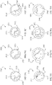
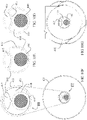
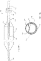
- Figs. 1A-D schematically illustrate an exemplary balloon catheter 1000 comprising a combined infusion-guidewire lumen (referred to as infusion lumen 1114) with selective valving mechanism 1300.
- Catheter 1000 includes a shaft 1100 having a length, a proximal end 1001 and a distal end 1002, and a wall enclosing infusion lumen 1114 which is extending along shaft's 1100 length and opened at both proximal end 1001 and distal end 1002 with corresponding proximal opening 1112 and distal opening 1118.
- Infusion lumen 1114 is further opened with a lateral infusion opening 1116 (or optionally a number of openings) disposed in shaft's 1100 wall between proximal end 1001 and distal end 1002.
- An inflatable member 1200 is connected to shaft 1100 adjacent its distal end, distal to lateral infusion opening 1116.
- Inflatable member 1200 may be a compliant balloon, a semi-compliant balloon or a non-compliant balloon.
- a valving mechanism may be any type of controller, such as a mechanical device, for selectively controlling a flow parameter of a fluid, for example a flow rate.
- a valving mechanism may be set between two or more modes that inhibit fluid flow by different amounts. In some cases, the modes may include a fully closed mode in which flow is substantially absent, and a fully opened valve in which fluid is allowed to travel substantially unhindered by the valving mechanism. Intermediate flow restrictions are also possible.
- a valving mechanism includes an elongated member such as a wire (e.g., a guide wire) operational to selectively pass through or withdraw from an infusion lumen portion sized and shaped substantially the same as external boundaries of a correlating portion thereof, being substantially narrowed as compared to a proximal portion of the infusion lumen located between a fluid inlet and a fluid outlet, such that when the wire occupies the narrowed infusion lumen portion then no flow or at least substantially no flow will pass therethrough.
- a wire e.g., a guide wire
- other valving means may be applied so that no fluid may pass through the narrowed infusion lumen portion also when the obstructing wire is absent, so that all or at least substantially all fluid will be delivered through a fluid outlet that is positioned proximal to the narrowed infusion lumen portion.
- guidewire-based valving mechanism 1300 may be provided in infusion lumen 1114 distal to lateral infusion opening 1116.
- Valving mechanism 1300 is selectively operable to block distal opening 1118 of infusion lumen 1114 such that fluid passing distally through infusion lumen 1114 shall exit mainly or solely through lateral infusion opening 1116 rather than through distal opening 1118.
- flow may pass via distal opening 1118 at all or in a greater rate.
- infusion lumen 1114 defines a first segment 1320, extending between proximal opening 1112 and a boundary 1340 (shown adjacent to lateral infusion opening 1116 although it may be further distal), and a second segment 1330, extending between boundary 1340 and distal opening 1118.
- first segment 1320 infusion lumen 1114 has a first minimal cross section area
- second segment 1330 infusion lumen 1114 has a second minimal cross section area smaller than the first minimal cross section than in first segment 1320.
- Valving mechanism 1300 includes an elongated member, preferably a guide wire 1310 selectively disposable in infusion lumen 1114 at first segment 1320 and/or second segment 1330.
- Guide wire 1310 is sized and configured to pass through proximal opening 1112, infusion lumen 1114 and/or distal opening 1118, and therefore allow an over-the-wire delivery of catheter 1000 thereupon.
- catheter 1000 is configures for rapid exchange deliveries.
- the second minimal cross section is sized and shaped such that guide wire 1310 can be selectively fit, snugly, in the second minimal cross section in order to achieve blocking of distal opening 1118 and/or second segment 1330 distal to lateral infusion opening 1116.
- the second minimal cross section is circular whereas the first minimal cross section is sized and shaped to virtually enclose a circle with identical dimensions to said second minimal cross section (as shown in the shape difference of infusion lumen 1114 in Fig. 1B vs. Fig. 1C ).
- the first minimal cross section may be of any shape such as circular, elliptic or crescent. Figs.
- FIG. 4A-B schematically illustrate cross sections of two other possible exemplary catheter portions 1000' and 1000" which comprise combined infusion-guidewire lumens 1114' and 1114", respectively.
- Both catheters 1000' and 1000" are over-the-wire type balloon catheters.
- an inner wall 1125' dividing between infusion lumen 1114' and inflation lumen 1124' is partially curved to allow partial nesting with part of a guide wire 1310' periphery in contact.
- Other part of guide wire periphery not in contact with inner wall 1125' is opened at least partially to infusion lumen 1114' interior so that fluid passing in the lumen may contact it.
- Fig. 4B shows infusion lumen 1114" and inflation lumen 1124" divided with a straight inner wall 1125", while guide wire 1310" is mostly opened to infusion lumen 1114" interior and may be only tangential to inner wall 1125".
- a method for operating a balloon catheter comprising at least one of the following steps (not necessarily in same order):
- steps 3 and 4 are performed simultaneously and/or in overlap.
- guide wire 1310 is selectively occupying or withdrawn from second segment 1330 in infusion lumen 1114 according to need.
- catheter 1000 first engages guide wire 1310 by inserting it via distal opening 1118, or alternatively, by inserting guide wire 1310 in infusion lumen 1114 via proximal opening 1112.
- the infusing occurs while the inflatable member is filled and/or expanded, optionally fully or partially.
- the inflatable member is deflated after the infusing.
- the inflating generates a dilatation force in a magnitude above a mechanical yield point of a stenotic blood vessel wall.
- the mechanical interaction between the filled and/or expanded inflatable member with the blood vessel portion in contact creates a sealing thus obstructing and/or diminishing substantially a fluid passing therebetween.
- a valving mechanism may include an additional valve or a seal for sealing around a guide wire passing therethrough, and/or selectively seal an opening or a segment of an infusion lumen when the guide wire is removed or otherwise absent.
- a catheter includes at least one one-way valve allowing a guide wire passing therethough while sealing fluid passage.
- the one-way valve is disposed adjacent to catheter's distal end and/or between a distal opening and a lateral infusion opening in the infusion lumen.
- the one-way valve is disposed adjacent to catheter's proximal end and/or between a proximal opening and a lateral infusion opening in the infusion lumen.
- the catheter and/or the valving mechanism includes a septum seal.
- Figs. 2A-B schematically illustrate portions in cross section of an exemplary balloon catheter 2000 and seals provided therein.
- Fig. 2A shows a proximal portion of balloon catheter 2000, comprising a wall 2100 enclosing an infusion lumen 2114 openable at proximal infusion inlet or port 2112 to an infusion fluid source (not shown), as well as an inflation lumen (not shown) openable to proximal inflation port 2122.
- proximal valving mechanism 2400 includes a proximal seal 2410 in the form of a "wire seal" adapted to maintain sealing around periphery of guide wire 2310, if present as shown.
- proximal seal 2410 may include a plurality of overlapping seal segments adapted to extend or narrow against outer periphery of the guide wire while maintaining sealing.
- proximal valving mechanism 2400 may also include a zero seal (which is "normally sealing"), in addition to the wire seal, not shown, adapted to seal fluid backflow through proximal infusion valve port 2112 when a wire is absent.
- a zero seal which is "normally sealing”
- Fig. 2B shows a distal portion of balloon catheter 2000 in which an inflatable member (balloon 2200) is fixated thereto.
- Infusion lumen 2114 is opened to outer environment with a lateral infusion opening 2116.
- a proximal valving mechanism 2300 comprising a septum seal 2320, optionally made of a highly elastic and/or a viscoelastic material, allowing distal sealing either if guide wire 2310 is absent (not shown) or passes therethrough (as shown).
- Figs. 3A-B schematically illustrate portions in cross section of a different exemplary balloon catheter 3000 and optional exemplary seals provided therein.
- Balloon catheter 3000 includes a wall 3100 enclosing an infusion lumen 3114 openable at a proximal infusion inlet port 3112 to an infusion fluid source (not shown), as well as an inflation lumen (not shown) openable to proximal inflation port 3122.
- An inflatable member (balloon 3200) is fixated at distal portion of catheter 3000.
- guide wire 3310 is passable through infusion lumen 3114 however it does not pass through proximal infusion port 3112 but rather through a dedicated guide wire port 3130. Therefore a proximal valving mechanism 3400 comprising an O-ring or a septum seal 3410, is used in guide wire port 3130 in order to avoid backflow of infusion fluid therethrough.
- infusion lumen 3114 is shown opened to outer environment with a lateral infusion outlet or opening 3116.
- a distal valving mechanism 3300 comprising a normally closed seal 3320 adapted to maintain sealing therethrough to infusion fluids either if guide wire 3310 passes therethrough or is absent.
- seal 3320 is an inflatable doughnut shaped, optionally continuously pressurized, so that it maintains a minimal sized core opening changeable from zero (when guide wire 3310 is absent) to outer diameter of guidewire 3310 if it passes therethrough.
- balloon catheter 3000 ends distally with a soft, elastic and/or pliable descending conic member 3118 which is normally tapered with a distal inner diameter substantially smaller than its proximal inner diameter at least at non-stressed and/or non-stretched form. If stretched out, for example in case a guide wire passes therethrough and having dimensions greater than those imposed by the non-stretched conic member 3118, it maintains a sealed distal end around outer boundaries of conic member 3118.
- Such sealing function may achieve at least one of: blocking fluid therethough from infusion lumen to our environment of any infusion fluid such as saline or medicament, and/or blocking fluid travel therethrough from outer environment and into infusion lumen of body fluid such as blood.
- conic member 3118 is designed, sized and/or configured such that guide wires having outer diameters between 0.25 mm (0.01") to 5.1 mm (0.2"), optionally 0.46 mm (0.018") to 0.89 mm (0.035”) or higher or lower or intermediate, are unhinderly passable therethrough, and optionally also stretching it at least partially to a radially extended form.
- conic member 3118 is normally sealed so that in absence of any wire extending therethrough it is fully compressed and sealed to fluids, at least at its distal-most portion.
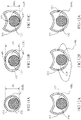
- FIG. 5A-H schematically illustrate cross sections in portions of different exemplary catheters, in accordance with embodiments of the present invention. All these cross sections represent portions of corresponding infusion lumens, each extending between a distal fluid inlet and a proximal fluid outlet.
- Fig. 5A shows a portion 3510 having a circular cross section with a wall 3511 enclosing a first infusion lumen 3512 with a dedicated area 3513 for partial nesting of a guidewire (not shown) shaped to enclose most of guidewire's periphery, and a second inflation lumen 3514.
- portion 3510 is of a 1.83 mm (5.5 French (F)) PTA catheter whereas infusion lumen 3512 area is about 1.2 mm 2 and inflation lumen 3514 area is about 0.34 mm 2 .
- Fig. 5B shows a portion 3520 having a circular cross section with a wall 3521 enclosing a first infusion lumen 3522 with a dedicated area 3523 for partial nesting of a guidewire (not shown) shaped to enclose approximately half of guidewire's periphery, and a second inflation lumen 3524.
- portion 3520 is of a 1.83 mm (5.5F) PTA catheter whereas infusion lumen 3522 area is about 1.28 mm 2 and inflation lumen 3524 area is about 0.31 mm 2 .
- Fig. 5C shows a portion 3530 having a circular cross section with a wall 3531 enclosing a first infusion lumen 3532 with a dedicated area 3533 for partial nesting of a guidewire (not shown) shaped to enclose most of guidewire's periphery, and a second inflation lumen 3534.
- portion 3530 is of a 1.67 mm (5F) occlusion balloon catheter whereas infusion lumen 3532 area is about 0.82 mm 2 and inflation lumen 3514 area is about 0.54 mm 2 .
- Fig. 5D shows a portion 3540 having a circular cross section with a wall 3541 enclosing a first infusion lumen 3542 with a dedicated area 3543 for partial nesting of a guidewire (not shown) shaped to enclose approximately half of guidewire's periphery, and a second inflation lumen 3544.
- portion 3540 is of a 2 mm (6F) PTA catheter whereas infusion lumen 3542 area is about 1.52 mm 2 and inflation lumen 3444 area is about 0.5 mm 2 .
- infusion lumen 3542 area is about 1.52 mm 2
- inflation lumen 3444 area is about 0.5 mm 2 .
- portion 3550 shows a portion 3550 having a circular cross section with a wall 3551 enclosing a first infusion lumen 3552 with a dedicated area 3553 for partial nesting of a guidewire (not shown) shaped to enclose most of guidewire's periphery, and a second inflation lumen 3554.
- portion 3550 is of a 1.67 mm (5F) occlusion balloon catheter whereas infusion lumen 3552 area is about 1.09 mm 2 and inflation lumen 3554 area is about 0.27 mm 2 .
- infusion lumen 3552 area is about 1.09 mm 2
- inflation lumen 3554 area is about 0.27 mm 2 .
- portion 3560 shows a portion 3560 having a circular cross section with a wall 3561 enclosing a first infusion lumen 3562 with a dedicated area 3563 for partial nesting of a guidewire (not shown) shaped to enclose most of guidewire's periphery, and a second inflation lumen 3564.
- portion 3560 is of a 2 mm (6F) PTA catheter whereas infusion lumen 3562 area is about 1.48 mm 2 and inflation lumen 3564 area is about 0.69 mm 2 .
- Fig. 5G shows a portion 3570 having a circular cross section with a wall 3571 enclosing a first infusion lumen 3572, a second guidewire lumen 3573 and a third inflation lumen 3574.
- portion 3570 is of a 1.83 mm (5.5F) PTA catheter whereas infusion lumen 3572 area is about 0.49 mm 2 , guidewire lumen 3573 area is about 0.69 mm 2 and inflation lumen 3574 area is about 0.35 mm 2 .
- Fig. 5H shows a portion 3580 having a circular cross section with a wall 3581 enclosing a first infusion lumen 3582 with enough space yet without a dedicated area for partial nesting of a guidewire (not shown), and a second inflation lumen 3583.
- portion 3580 is of a 1.83 mm (5.5F) PTA catheter whereas infusion lumen 3582 area is about 1.49 mm 2 and inflation lumen 3583 area is about 0.27 mm 2 .
- FIG. 6A-B schematically illustrate an exemplary infusion lumen 110IL, as part of a catheter, comprising a first exemplary valving mechanism, in accordance with embodiments of the present invention.
- the catheter includes an infusion wall 110 enclosing infusion lumen 110IL that extends axially therealong.
- Infusion wall includes a proximal wall segment 115, a distal wall segment 113 and an intermediate wall segment 111 extending therebetween.
- Proximal wall segment 115 comprises a proximal guidewire opening 118 and distal wall segment 113 comprises a distal guidewire opening 119.
- a guidewire 120 is shown extending through infusion lumen 110IL having its distal part provided through distal guidewire opening 119 and its proximal part provided through proximal guidewire opening 118. During treatment, including catheter delivery, deployment or withdrawal, guidewire 120 may pass into infusion lumen 110IL through proximal guidewire opening 118 or through distal guidewire opening 119.
- Proximal wall segment 115 adjoins intermediate wall segment 111 with a widening 114, and intermediate wall segment 111 adjoins distal wall segment 113 with a narrowing 112. Widening 114 and/or narrowing 112 may be gradual or steep.
- Intermediate wall segment 111 includes a fluid inlet 116 appositional to proximal wall segment 115 and a fluid outlet 117 appositional to distal wall segment 113.
- Infusion lumen 110IL is shown during fluid dispersion when fluid inlet 116 is located outside a patient body and fluid outlet 117 is located inside the patient body in a specific location in a bodily lumen, optionally a blood vessel such as a vein or an artery, optionally in apposition to a lesion or a stenosis.
- a fluid inlet flow rate F in travels in infusion lumen 110IL through fluid inlet 116 while a fluid outlet flow rate F out 1 travels out of infusion lumen 110IL to a target location inside patient's body through fluid outlet 117.
- infusion lumen 110IL in distal wall segment 113 is sized, shaped, and/or inner surface of distal wall segment 113 is textured, such, to build a distal pressure gradient allocating a distal flow rate F out 3 through distal guidewire opening 119, being 40% or less fluid outlet flow rate F out 1 through fluid outlet 117, optionally 20% or less, optionally 10% or less, optionally 5% or less, optionally, 2% or less, or higher, or lower, optionally null, or an intermediate percentage; optionally when distal wall segment 113 is unobstructed, such as with guidewire 120, or optionally when distal wall segment 113 is obstructed with guidewire 120.
- infusion lumen 110IL in proximal wall segment 115 is sized, shaped, and/or inner surface of proximal wall segment 115 is textured, such, to build a distal pressure gradient allocating a negative flow rate F out 2 through proximal guidewire opening 118, being 40% or less fluid outlet flow rate F out 1 through fluid outlet 117, optionally 20% or less, optionally 10% or less, optionally 5% or less, optionally, 2% or less, or higher, or lower, optionally null, or an intermediate percentage; optionally when proximal wall segment 115 is unobstructed, such as with guidewire 120, or optionally when proximal wall segment 115 is obstructed with guidewire 120.
- guidewire 120 is a 0.89 mm (0.035”) guidewire, or a 0.64 mm (0.025”) guidewire, or a 0.46 mm (0.018”) guidewire, or a 0.36 mm (0.014”) guidewire, or lower, or higher, or intermediate in size.
- Distal pressure gradient and/or proximal pressure gradient is optionally determined according to an infusion fluid viscosity of at least 0.65 millipascal second (centipoises (“cP”)), or optionally of at least 3 millipascal second (cP), or optionally at least 6 millipascal second (cP), or optionally at least 8 millipascal second (cP); considering that water viscosity at a temperature of 37 °C is approximately 0.69 millipascal second (cP), blood viscosity at same temperature is approximately 3 to 4 millipascal second (cP), and iodine based contrast media is commonly between approximately 4 millipascal second (cP) to approximately 12 millipascal second (cP).
- centipoises centipoises
- a cross section area of fluid outlet 117 D prx divided by a cross section area A of distal guidewire opening 119 is at least 1.5, optionally at least 2, optionally at least 3, optionally at least 5, optionally at least 10, or higher, or lower, or an intermediate value.
- a cross section area D gw of proximal guidewire opening 118 is equal to or less than cross section area A distal guidewire opening 119.
- a cross section of infusion lumen 110IL in distal wall segment 113 and/or in proximal wall segment 115 is circular and 0.3 mm to 1.5 mm in diameter.
- proximal wall segment 115 and/or distal wall segment 113 is at least 10 mm in length, optionally at least 20 mm, optionally at least 50 mm, optionally at least 100 mm, or higher, or lower, or has an intermediate value.
- distal guidewire opening 119 and/or proximal guidewire opening 118 is 0.3 mm to 2 mm in diameter, optionally 0.5 mm to 1.5 mm, optionally 0.9 to 1 mm, or optionally 0.3 mm to 0.9 mm, or optionally about 0.95 mm.
- Infusion lumen 110IL at intermediate wall segment 111 may take any of a plurality of cross sections forms, as long as they are sized and shaped to virtually enclose a circle with dimensions equal or higher than to outer dimensions of guidewire 120 or a thicker guidewire that can be used with the catheter.
- Figs. 11A-C schematically illustrate different exemplary cross section shapes for of infusion lumen 110IL at intermediate wall segment 111, in accordance with embodiments of the present invention.
- Fig 11A shows a circular cross section of intermediate wall segment 111 with internal diameter ID equal or greater than guidewire 120 diameter.
- Fig 11B shows a cross section of infusion lumen 110IL at intermediate wall segment 111 being noncircular shaped with a smallest distance APL between antipodal points AP1 and AP2 at an inner boundary thereof.
- Fig. 11C shows a cross section of infusion lumen 110IL at intermediate wall segment 111 being crescent shaped with a smallest distance ARL between two opposing arcs AR1 and AR2 at an inner boundary thereof.
- distance APL and/or ARL is at least 0.3 mm, optionally at least 0.5 mm, optionally at least 0.9 mm, optionally at least 1.5 mm, optionally at least 3 mm, or higher, or lower, or an intermediate value.
- the cross section area of infusion lumen 110IL at intermediate wall segment 111 is at least 1 mm2, optionally 1.5 mm 2 , optionally at least 1.75 mm 2 , optionally at least 2 mm 2 , optionally at least 4 mm 2 , or higher, or lower, or of any intermediate value.
- Fluid outlet 117 may include any number of openings of any form and size, and of any arrangement with any pattern.
- fluid outlet may include at least one hole (i.e. a through opening), at least one slit and/or at least one pressure sensitive opening.
- the at least one slit is configured to open above a predetermined infusion pressure, optionally of at least 1 bar, optionally at least 2 bar, optionally at least 4 bar, or higher, or lower, or intermediate.
- the overall area of fluid outlet 117 is equal or higher than cross section area (minimal or average, in case it is not constant) of infusion lumen 110IL at intermediate wall segment 111, optionally equal or higher than 1.5 times its size, optionally equal or higher than 2 times its size, optionally equal or higher than 5 times its size, or higher, or lower, or an intermediate value.
- the overall area of fluid outlet 117 is equal or higher than cross section area of infusion lumen 110IL at intermediate wall segment 111 less cross section area of guidewire 120.
- fluid outlet 117 may include a number of openings, optionally provided in form of series, optionally around a periphery of the catheter and/or along a portion of its length.
- At least one opening may be directly opposing an at least one opening at an opposing wall portion of the catheter, and/or at least one opening may be peripherally and/or longitudinally offset to another at least one opening at a different wall portion of the catheter.
- Figs. 12A-C schematically illustrate different exemplary fluid outlet types and/or distribution, in accordance with embodiments of the present invention.
- Fig. 12A shows infusion lumen 110IL at intermediate wall segment 111 with a crescent cross section and a single hole as fluid outlet 117.
- Fig. 12B shows infusion lumen 110IL at intermediate wall segment 111 with a crescent cross section and a number of holes as fluid outlet 117.
- Fig. 12C shows infusion lumen 110IL at intermediate wall segment 111 with a crescent cross section and a single pressure sensitive slit as fluid outlet 117.
- the catheter also comprises an inflatable member and an inflation wall enclosing an inflation lumen with the infusion wall along a length thereof.
- the inflatable member may be a dilatation balloon comprising a non-compliant or a semi-compliant material, or it may be an occlusion balloon comprising a compliant material.
- Figs. 7A-B schematically illustrate balloon catheter incorporating exemplary valving mechanisms differentiated by balloon location relative to fluid outlet, in accordance with embodiments of the present invention.
- Fig. 7A shows a catheter 100 which includes infusion wall 110 enclosing infusion lumen 110IL, similar to as described above.
- Catheter 100 also includes an inflatable member 136 and an inflation wall 130 enclosing an inflation lumen 130IL with infusion wall 110 along part of inflation lumen length.
- Inflation lumen 130IL includes an inflation inlet 132, optionally located in relative opposition to proximal guidewire opening 118 and/or to fluid inlet 116, as well as an inflation outlet 134 located within the sealed inner boundary of inflatable member 136.
- Inflatable member may be configured as a dilatation and/or occlusion balloon. As shown, in this example, dilatation member 136 is provided in between fluid outlet 117 and distal guidewire opening 119. This will allow dispersion of fluid such as contrast enhancing media, flushing fluid, dissolvent and/or medicament only proximal and optionally adjacent to inflatable member 136.
- Fig. 7B shows a catheter 140 which includes infusion wall 110 enclosing infusion lumen 110IL, similar to as described above.
- Catheter 140 also includes an inflatable member 136 and an inflation wall 130 enclosing an inflation lumen 130IL with infusion wall 110 along part of inflation lumen length.
- Inflation lumen 130IL includes an inflation inlet 132, optionally located in relative opposition to proximal guidewire opening 118 and/or to fluid inlet 116, as well as an inflation outlet 134 located within the sealed inner boundary of inflatable member 136.
- Inflatable member may be configured as a dilatation and/or occlusion balloon.
- fluid outlet 117 includes a proximal-most opening 142 and a distal-most opening 144, wherein inflatable member 136 extends therebetween. This will allow dispersion of fluid such as contrast enhancing media, flushing fluid, dissolvent and/or medicament proximally and distally, and optionally adjacent, to inflatable member 136.
- FIGs. 8A-B schematically illustrate an exemplary infusion lumen 210IL, as part of a catheter, comprising an exemplary valving mechanism with additional backflow seal, in accordance with embodiments of the present invention.
- the catheter includes an infusion wall 210 enclosing infusion lumen 210IL that extends axially therealong.
- Infusion wall includes a proximal wall segment 215, a distal wall segment 213 and an intermediate wall segment 211 extending therebetween.
- Proximal wall segment 215 comprises a proximal guidewire opening 218 and distal wall segment 213 comprises a distal guidewire opening 219.
- a guidewire 220 is shown extending through infusion lumen 210IL having its distal part provided through distal guidewire opening 219 and its proximal part provided through proximal guidewire opening 218.
- guidewire 220 may pass into infusion lumen 210IL through proximal guidewire opening 218 or through distal guidewire opening 219.
- Proximal wall segment 215 adjoins intermediate wall segment 211 with a widening 214, and intermediate wall segment 211 adjoins distal wall segment 213 with a narrowing 212.
- Widening 214 and/or narrowing 212 may be gradual or steep.
- Intermediate wall segment 211 includes a fluid inlet 216 appositional to proximal wall segment 215 and a fluid outlet 217 appositional to distal wall segment 213.
- a guidewire seal 230 is provided in infusion lumen 210IL between fluid inlet 216 and proximal guidewire opening 218.
- guidewire seal 230 is an inflatable annular seal which includes an annular inflatable body 231 having a lumen 232, and a seal inlet 234.
- inflatable body 231 has an outer periphery, fixed to infusion wall 210, and an inner periphery surrounding lumen 232 with a selectively changeable inner diameter.
- seal inlet 234 is provided adjacent and in direct fluid communication with fluid inlet 216, optionally dividing an intake passage at fluid inlet 216 to seal inlet 234 and to an infusion inlet 233, so that when fluid is forced through fluid inlet 216 it will be divided between filling infusion lumen 210IL and fluid delivery through fluid outlet 217, and inflating guidewire seal 230 such that its lumen 232 decreases in diameter down to a minimal degree.
- guidewire seal 230 may decrease in inner diameter below to a predetermined guidewire diameter. When guidewire seal 230 is deflated its lumen 232 is relatively enlarged so that guidewire 220 can travel freely therethrough (as shown in Fig.
- inflatable body 231 includes a compliant material capable of conforming to guidewire boundaries at certain inner pressures.
- Figs. 9A-B schematically illustrate an exemplary infusion lumen 310IL, as part of a catheter, comprising an exemplary valving mechanism with additional exemplary proximal and distal sealing sets, in accordance with embodiments of the present invention.
- the catheter includes an infusion wall 310 enclosing infusion lumen 310IL that extends axially therealong.
- Infusion wall includes a proximal wall segment 315, a distal wall segment 313 and an intermediate wall segment 311 extending therebetween.
- Proximal wall segment 315 comprises a proximal guidewire opening 318 and distal wall segment 313 comprises a distal guidewire opening 319.
- a guidewire 320 is shown extending through infusion lumen 310IL having its distal part provided through distal guidewire opening 319 and its proximal part provided through proximal guidewire opening 318.
- guidewire 320 may pass into infusion lumen 310IL through proximal guidewire opening 318 or through distal guidewire opening 319.
- Proximal wall segment 315 adjoins intermediate wall segment 311 with a widening 314, and intermediate wall segment 311 adjoins distal wall segment 213 with a narrowing 312. Widening 314 and/or narrowing 312 may be gradual or steep.
- Intermediate wall segment 311 includes a fluid inlet 316 appositional to proximal wall segment 315 and a fluid outlet 317 appositional to distal wall segment 313.
- a proximal guidewire seal 330 is provided in infusion lumen 310IL between fluid inlet 316 and proximal guidewire opening 318.
- proximal guidewire seal 330 is an inflatable annular seal which includes an annular inflatable body 331 having a lumen 332, and a seal inlet 334.
- inflatable body 331 has an outer periphery, fixed to infusion wall 310, and an inner periphery surrounding lumen 332 with a selectively changeable inner diameter.
- seal inlet 334 is provided adjacent and in direct fluid communication with fluid inlet 316, optionally dividing an intake passage at fluid inlet 316 to seal inlet 334 and to an infusion inlet 333, so that when fluid is forced through fluid inlet 316 it will be divided between filling infusion lumen 310IL and fluid delivery through fluid outlet 317, and inflating proximal guidewire seal 330 such that its lumen 332 decreases in diameter down to a minimal degree.
- a distal guidewire seal 340 is also provided in infusion lumen 310IL between fluid outlet 317 and distal guidewire opening 319.
- distal guidewire seal 340 is an inflatable annular seal which includes an annular inflatable body 341 having a lumen 342, and a seal inlet 344.
- inflatable body 341 has an outer periphery, fixed to infusion wall 310, and an inner periphery surrounding lumen 342 with a selectively changeable inner diameter.
- seal inlet 334 is provided in infusion lumen 310IL so that when pressure arises therein, fluid is forced through fluid outlet 317 in parallel or after to inflating distal guidewire seal 340 such that its lumen 342 decreases in diameter down to a minimal degree.
- proximal guidewire seal 330 and distal guidewire seal 340 may decrease in inner diameter below to a predetermined guidewire diameter.
- guidewire seals 330 and 340 deflates, their lumens 332 and 342, respectively, are relatively enlarged so that guidewire 320 can travel freely therethrough whereas when they are inflated to a certain degree, optionally up to a maximal inflation volume, lumens 332 and 342 decrease in diameter to equal or less than guidewire 320 outer boundaries (as shown in Fig. 9B ) therefore sealing a fluid passage therebetween.
- inflatable bodies 331 and 341 include compliant material capable of conforming to guidewire boundaries at certain inner pressures.
- a proximal zero seal 352 is provided between fluid inlet 316 and proximal guidewire opening 318.
- a distal zero seal 354 is provided between fluid outlet 317 and distal guidewire opening 319.
- Zero seals 352 and 354 are normally closed to fluid flow at the absence of a guidewire passing therethrough.
- Fig. 9A shows a scenario in which a guidewire is absent from infusion lumen 310IL yet by delivering a fluid F in therein through fluid inlet 316 a fluid F out is delivered out only through fluid outlet 317 and not through guidewire openings 318 and 319 since that zero seals 352 and 354 are closed and sealed to fluid passage therethrough.
- 9B shows another scenario in which guidewire 320 travels through infusion lumen 310IL and guidewire openings 318 and 319, forcing zero seals 352 and 354 to open, yet by delivering a fluid F in in infusion lumen 310IL it can only be delivered (as fluid F out ) through fluid outlet 317 since that both guidewire seals are inflated and seal fluid passage between them and guidewire 320.
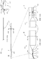
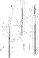
- Balloon catheter 400 includes an elongated shaft 410 connected at its proximal end with a triple connector 420.
- An inflatable angioplasty balloon 430 is provided along a portion of its distal end.
- Shaft 410 encloses an infusion lumen 414 and an inflation lumen 415 separated and sealed to infusion lumen 414 with a wall 413.
- Infusion lumen 414 extends along entire length and opened at both ends of catheter 400, having a proximal guidewire opening 422 and a distal guidewire opening 424, allowing in size and shape passage in between and therethrough of a guidewire 440.
- Infusion lumen 414 also includes a fluid inlet 421 in triple connector 420 distally to proximal guidewire opening 422.
- Fluid inlet 421 comprises a single opening and connection means (optionally a luer connection to a syringe) for allowing selective introduction into infusion lumen 414 of at least type of fluid, such as a contrast enhancing medium, flushing fluid (e.g., saline), medicament, chemical or biological compounds, or others.
- a fluid outlet 412 is provided proximally and close (optionally adjacent) to balloon 430 and allows delivery of fluid outside infusion lumen 414 proximally and adjacent to balloon 430.
- Fluid outlet 412 may include a single opening (as shown) or a plurality of openings of any chosen number, form, arrangement or other.
- Inflation lumen 415 extends about most of infusion lumen 414 length, between an inflation inlet 423 in triple connector 420, distally to proximal guidewire opening 422 and in general opposite direction to fluid inlet 421, and an inflation outlet opened to inner volume of balloon 430.
- Inflation inlet 423 comprises a single opening and connection means (optionally a luer connection to a syringe) for allowing selective delivery into or withdrawal from inflation lumen 415 of inflation fluid (optionally saline, optionally with contrast enhancing agent) for inflating and deflating, respectively, balloon 430.
- Infusion lumen 414 includes a proximal segment 409 extending at least partially between proximal guidewire opening 422 and fluid inlet 421, a distal segment 418 extending at least partially between fluid outlet 412 and distal guidewire opening 424, and an intermediate segment extending in between proximal segment 409 and distal segment 418.
- Proximal segment 409 and distal segment 418 have circular cross sections equal or slightly over cross section of guidewire 440 so that the guidewire can snugly fit therein yet can be passed freely either proximally or distally.
- the intermediate segment of infusion lumen 414 has a crescent shaped cross section which encloses a circular area equal or greater than cross section area of guidewire 440.
- Proximal segment 409 adjoins the intermediate segment with a gradual widening 419 and the intermediate segment adjoins distal segment 418 with a gradual narrowing 417.
- guidewire 440 in proximal segment 409 and distal segment 418 of infusion lumen 414 and substantial lengths thereof (greater than 20 mm, optionally about 50 mm, each) seals (fully or partially) fluid travel therethrough, so that most or all infusion fluid entering infusion lumen 414 through fluid inlet 421 will be delivered through fluid outlet 412 and not through proximal guidewire opening 422 and distal guidewire opening 424, at least as long as guidewire 440 nests therein and obstructs them.
- Balloon 430 includes a non-compliant or semi-compliant inflatable membrane 431 fixated in both ends to shaft 410 outer periphery with a proximal constriction 432 and a distal constriction 433.
- An optional soft tip 434 is provided for improving safety to vasculature during delivery.
- Balloon 430 is configured for dilating a narrowed portion, optionally stenotic, of a blood vessel by inflating it under a moderate to high pressure, according to anatomic location and blood vessel diameter at the treatment location.
- Inflation lumen 415 being completely sealed to infusion lumen 414 allows an independent applicability of balloon 430 with respect to infusion and fluid delivery through fluid outlet 412, so that fluid can be delivered if balloon 430 is inflated, deflated or while being in a process of inflation or deflation.
- Delivering contrast media, agent or medicament proximally to balloon 430 when inflated has some advantages as balloon 430 acts also as an occlusion balloon enabling this way a localized delivery and treatment instead of systemic.
- a fluid outlet of a dilatation balloon catheter has a single, substantially large opening.
- the total opened area of the opening is equal to or greater than a minimal cross section area of the infusion lumen, in a portion proximal to the opening.
- the total opened area is equal or greater than a minimal cross section area of the infusion lumen, in a portion proximal to the opening less a cross section area of a guidewire of a minimally allowed diameter, or of a maximally allowed diameter, or an intermediate value.
- total opened area of fluid outlet is at least 0.5 mm 2 , optionally at least 1 mm 2 , optionally at least 2 mm 2 , optionally at least 5 mm 2 , optionally about 1.2 mm 2 , optionally about 2.5 mm 2 or higher, or lower, or an intermediate value.
- a structural fortification is added to the catheter shaft about the opening.
- Figs 13 , 14 and 15 disclose three exemplary types of fortifications.
- the device illustrated in Figures 10A-10I is made according to the principles illustrated schematically in Figure 7A .
- the lengths of the narrowed portions of the infusion lumen at the proximal and distal portions of the catheter (designated 113 and 115 in Figure 7A ) to be 20 mm long or more, and also for the infusion opening positioned proximal to the balloon (designated 117 in Figure 7A ) to be a single opening having a cross sectional area equal to or greater than the minimal cross sectional area of the infusion lumen in between the narrowed portions minus the cross sectional area of the largest diameter allowed guidewire.
- the cross sectional area of the largest diameter allowed guidewire is approximately equal to the cross sectional area of at least the distal narrowed portion of the infusion lumen.
- the cross sectional area of the infusion opening can thus be expressed as equal to or greater than the minimal cross sectional area of the larger cross section portion of the infusion lumen between the narrowed portions (designated 111 in Figure 7A ), and the minimal cross sectional area of the distal narrowed portion of the infusion lumen.
- This implementation has the significant advantage that the relatively long lengths of the narrowed portions of the infusion lumen substantially seal the ends of the infusion lumen in the presence of the guidewire without the use of additional valving or clamping structures that complicate device construction, and the relatively large infusion opening provides a high volume outflow of infusate. This remains true even when the nesting of the guidewire in the narrowed portions of the infusion lumen is loose enough to allow easy sliding of the catheter structure over the guidewire.
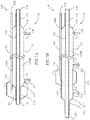
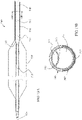
- Figs. 13A-B schematically illustrate cut views of an exemplary balloon catheter 500 with a single proximal fluid outlet 512 comprising a first exemplary fortification, in accordance with embodiments of the present invention.
- Balloon catheter 500 shown with its distal end includes an elongated shaft 510 and an inflatable angioplasty balloon 530 that is provided along a portion of its distal end.
- Shaft 510 encloses an infusion lumen 514 and an inflation lumen 515 separated and sealed to infusion lumen 514 with a wall 513.
- Inflation lumen 515 being completely sealed to infusion lumen 514 allows an independent applicability of balloon 530, so that fluid can be delivered if balloon 530 is inflated, deflated or while being in a process of inflation or deflation.
- Infusion lumen 514 includes a distal guidewire opening 524 allowing passage therethrough of a guidewire (not shown) optionally one of several possibly prescribed guidewires.
- a fluid outlet 512 is provided proximally and close (optionally adjacent) to balloon 530 and allows delivery of fluid outside infusion lumen 514 proximally and adjacent to balloon 530.
- Infusion lumen 514 narrows with a gradual narrowing 517 into a distal segment 518. Until narrowing 517, infusion lumen 514 has a crescent shaped cross section which encloses a circular area equal or greater than cross section area of a guidewire with a maximally allowed diameter.
- Distal segment 518 has circular cross sections equal or slightly over cross section of said guidewire so that the guidewire can snugly fit therein yet can be passed freely either proximally or distally.
- Infusion lumen 514 is configured such that most or all infusion fluid entering therein will be delivered through fluid outlet 512 and not through distal guidewire opening 524, at least as long a prescribed guidewire nests therein and obstructs distal segment 518 and distal guidewire opening 524.
- Fluid outlet 512 has a single, substantially large opening with a total opened area being equal to or greater than the cross section area of infusion lumen 514 proximal to fluid outlet 512 less a cross section area of a guiderwire with a minimal prescribed diameter.
- the portion of shaft 510 about fluid outlet 512 is fortified with a mesh patch 545 optionally made from stainless steel in a rectangular shape curved to nest over shaft 510.
- the total opened area of fluid outlet 512 is calculated as the total area covered by the outline of fluid outlet 512 less the area covered by mesh 545 above fluid outlet 512.
- Mesh patch 545 is fixated to shaft 510 with a cover such as a flexible sleeve 540, optionally made from nylon, with a hole cut thereto enclosing fluid outlet 512. Therefore, fluid delivered through fluid outlet 512 will pass then through the portion of mesh insert 545 thereabove and then through the hole in sleeve 540.
- a cover such as a flexible sleeve 540, optionally made from nylon
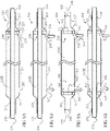
- Figs. 14A-B schematically illustrate cut views of an exemplary balloon catheter 600 with a single proximal fluid outlet 612 comprising a second exemplary fortification, in accordance with embodiments of the present invention.
- Balloon catheter 600 shown with its distal end includes an elongated shaft 610 and an inflatable angioplasty balloon 630 that is provided along a portion of its distal end.
- Shaft 610 encloses an infusion lumen 614 and an inflation lumen 615 separated and sealed to infusion lumen 614 with a wall 613.
- Inflation lumen 615 being completely sealed to infusion lumen 614 allows an independent applicability of balloon 630, so that fluid can be delivered if balloon 630 is inflated, deflated or while being in a process of inflation or deflation.
- Infusion lumen 614 includes a distal guidewire opening 624 allowing passage therethrough of a guidewire (not shown) optionally one of several possibly prescribed guidewires.
- a fluid outlet 612 is provided proximally and close (optionally adjacent) to balloon 630 and allows delivery of fluid outside infusion lumen 614 proximally and adjacent to balloon 630.
- Infusion lumen 614 narrows with a gradual narrowing 617 into a distal segment 618. Until narrowing 617, infusion lumen 614 has a crescent shaped cross section which encloses a circular area equal or greater than cross section area of a guidewire with a maximally allowed diameter.
- Distal segment 618 has circular cross sections equal or slightly over cross section of said guidewire so that the guidewire can snugly fit therein yet can be passed freely either proximally or distally.
- Infusion lumen 614 is configured such that most or all infusion fluid entering therein will be delivered through fluid outlet 612 and not through distal guidewire opening 624, at least as long a prescribed guidewire nests therein and obstructs distal segment 618 and distal guidewire opening 624.
- Fluid outlet 612 has a single, substantially large opening with a total opened area being equal to or greater than the cross section area of infusion lumen 614 proximal to fluid outlet 612 less a cross section area of a guiderwire with a minimal prescribed diameter.
- the portion of shaft 610 about fluid outlet 612 is fortified with a tube insert 640 optionally made from stainless steel and having an internal diameter equal or greater than a maximally allowed guidewire diameter, and an outer diameter equal or smaller than a circle enclosed in infusion lumen 614 between wall 613 and shaft 610.
- Tube insert 640 is fixated to shaft 610 optionally by soldering or gluing, or it may be freely disposed therein, optionally in a snug fit.
- Tube insert 640 includes a hole positioned such to enclose fluid outlet 612. Therefore, fluid delivered through fluid outlet 612 will pass first through the hole in tube insert 640.
- Figs. 15A-B schematically illustrate cut views of an exemplary balloon catheter 700 with a single proximal fluid outlet 712 comprising a third exemplary fortification, in accordance with embodiments of the present invention.
- Balloon catheter 700 shown with its distal end includes an elongated shaft 710 and an inflatable angioplasty balloon 730 that is provided along a portion of its distal end.
- Shaft 710 encloses an infusion lumen 714 and an inflation lumen 715 separated and sealed to infusion lumen 714 with a wall 713.
- Inflation lumen 715 being completely sealed to infusion lumen 714 allows an independent applicability of balloon 730, so that fluid can be delivered if balloon 730 is inflated, deflated or while being in a process of inflation or deflation.
- Infusion lumen 714 includes a distal guidewire opening 724 allowing passage therethrough of a guidewire (not shown) optionally one of several possibly prescribed guidewires.
- a fluid outlet 712 is provided proximally and close (optionally adjacent) to balloon 730 and allows delivery of fluid outside infusion lumen 714 proximally and adjacent to balloon 730.
- Infusion lumen 714 narrows with a gradual narrowing 717 into a distal segment 718. Until narrowing 717, infusion lumen 714 has a crescent shaped cross section which encloses a circular area equal or greater than cross section area of a guidewire with a maximally allowed diameter.
- Distal segment 718 has circular cross sections equal or slightly over cross section of said guidewire so that the guidewire can snugly fit therein yet can be passed freely either proximally or distally.
- Infusion lumen 714 is configured such that most or all infusion fluid entering therein will be delivered through fluid outlet 712 and not through distal guidewire opening 724, at least as long a prescribed guidewire nests therein and obstructs distal segment 718 and distal guidewire opening 724.
- Fluid outlet 712 has a single, substantially large opening with a total opened area being equal to or greater than the cross section area of infusion lumen 714 proximal to fluid outlet 712 less a cross section area of a guiderwire with a minimal prescribed diameter.
- the portion of shaft 710 about fluid outlet 712 is fortified with a sheet insert 740 optionally made from stainless steel in a rectangular shape curved to nest in shaft 710.
- Sheet insert 740 is fixated to shaft 710 optionally by soldering or gluing, or optionally the fortified portion and/or sheet insert 740 is deformed resulting in a tight fit.
- Tube insert 740 includes a hole positioned such to enclose fluid outlet 712. Therefore, fluid delivered through fluid outlet 712 will pass first through the hole in tube insert 740.
- Table 1 Exemplary sizes and indications of balloon catheters Indication Balloon diameter and length (mm) Catheter length (cm) Sheath size (mm) (F) Dilatation pressures: nominal and RPB (10 5 Pa) Guidewire size (mm) (Inches) PTA catheter for treating AV fistula or graft D: 5-12 50/80/135 2.0/2.33/2.67 Nom.: 8 0.89 L: 20/40/60/80 6/7/8 RPB: 18-30 0.035 PTA catheter for treating large blood vessels D: 14-18 80/120 2.67 Nom.: 8 0.89 L: 20/40/60 8 RPB: 10-12 0.035 PTA catheter for treating peripheral blood vessels D: 4-9 80/135 1.67-2.67 Nom.: 6-8 0.46/0.89 L: 20
Landscapes
- Health & Medical Sciences (AREA)
- Life Sciences & Earth Sciences (AREA)
- Heart & Thoracic Surgery (AREA)
- Animal Behavior & Ethology (AREA)
- Public Health (AREA)
- Anesthesiology (AREA)
- Hematology (AREA)
- Engineering & Computer Science (AREA)
- Veterinary Medicine (AREA)
- General Health & Medical Sciences (AREA)
- Biomedical Technology (AREA)
- Biophysics (AREA)
- Pulmonology (AREA)
- Vascular Medicine (AREA)
- Child & Adolescent Psychology (AREA)
- Media Introduction/Drainage Providing Device (AREA)
- Infusion, Injection, And Reservoir Apparatuses (AREA)
Description
- This application claims priority to
U.S. Provisional Application 61/752,649, filed on January 15, 2013 - The present invention, in some embodiments thereof, relates to medical devices, and in particular to balloon catheters applicable for treating blood vessels.
- Balloon catheters are well known and used in treating various conditions in blood vessels. Two main types of balloon catheters in that area are dilatation balloon catheter, used to treat narrowed or stenotic portions of the vessel and recover flow (e.g., angioplasty balloon catheters), and occlusion balloon catheters, used to temporarily block flow out of a vessel segment while infusing fluid (e.g., medicament, contrast enhancer or flushing material) therein.
- Some balloon catheters have at least three parallel functions, including: balloon inflation, travel over a guide wire, and infusion or dispersion of fluids therethrough. Such balloon catheters often include at least three lumens passing there along, including an inflation lumen, a guidewire lumen and an infusion lumen, correspondingly. In some occasions it is suggested to treat a blood vessel with a balloon catheter comprising an infusion exit opening located proximally to the balloon member, particularly if the balloon member is used for occlusion at least partially during infusion.
US 7,182,755 describes a use of an occlusion balloon catheter with a proximal infusion opening for treating hemodialysis vascular access.US 5,368,567 describes a dilatation balloon catheter with a proximal infusion opening. - In some such occasions, minimization of catheter's lumens cross-sections is advantageous. In one example, there may be a need for a small diameter catheter for intraluminal passage (e.g., 3F to 5F) so it is more complex to introduce three lumens. In a second example, there may be a need to fortify the catheter shaft for high pressure dilatations (as in vascular access recanalization in certain anatomies), so it may be advantageous to decrease overall lumens size in a certain shaft diameter.
- WIPO International Application Publication No.
WO 2012/110598 A1, published Aug. 23, 2012 , of Applicant Acrostak Corp. BVI, discloses a catheter comprising a balloon, an inflation lumen coupled to said balloon and an infusion wall enclosing an infusion lumen extending axially therealong according to the preamble ofclaim 1. - U.S. Patent Application Publication No.
US 2006/0253071 A1, published Nov. 09, 2006, in the name of Zattera , discloses the following. "A catheter for medical applications, suitable for being inserted into a duct comprising a first vessel and a second vessel which branches off from the first vessel. The catheter comprises a catheter body which extends from a proximal end to a distal end, a main cavity, which connects the proximal end to the distal end, and at least one opening, disposed at the distal end and suitable for perfusing a substance from the main cavity to the second vessel. The catheter, at the distal end, comprises first and second occluding means suitable for at least partially occluding the distal end so as to infuse the second vessel indirectly, creating a preferred flow of substance from the at least one opening to the second vessel.". -
U.S. Patent No. 5,908,407, issued June 01, 1999, in the name of Frazee, et al. , discloses the following. "A catheter for retroprofusing a venous junction formed by first, second and third veins, includes an elongate tube having a plurality of channels including a through-lumen extending between a proximal end and a distal end. A proximal balloon is inflatable to partially occlude the third vein, while a distal balloon is inflatable to partially occlude the second vein. An operative region of the catheter between the first and second balloons is adapted to pressurize the venous junction with arterial blood to produce retrograde blood flow in the first vein.". - U.S. Patent Application Publication No.
US 2010/0198186 A1, published Aug. 05, 2010, in the name of Ackermann , discloses the following. "A catheter assembly having a dual lumen proximal tubular portion including a guidewire lumen and an inflation lumen and a single lumen distal tubular portion that receives the guidewire and can additionally receive fluid. The catheter assembly includes flow passages in allow fluid to flow from the interior of the catheter to the exterior.". -
U.S. Patent No. 6,485,500 B1, issued Nov. 26, 2002, in the name of Kokish, et al. , discloses the following. "The emboli protection system provides one or more inflatable blocking balloons for isolation of a section of a blood vessel to prevent migration of emboli from the section during an interventional procedure, and fluid infusion and evacuation ports for flushing emboli from the isolated section. One embodiment provides for a distal blocking balloon catheter, over which an interventional device can be introduced, and a proximal blocking balloon catheter to be introduced over the interventional device for isolating a portion of a blood vessel to be treated. The blocking balloons can be perforated to provide the infusion ports, and thrombolytic inflation fluid may be used to break down and dissolve thrombus and plaque in the isolated portion of the blood vessel. The interventional therapeutic device such as an angioplasty balloon catheter may be incorporated into the distal blocking balloon catheter, or the distal and blocking proximal balloon catheters can be incorporated with the interventional therapeutic device together in one device. Infusion ports may also be provided in either or both of the distal and proximal blocking catheters.". -
U.S. Patent No. 5,267,979 A, issued Dec. 07, 1993, in the name of Appling, et al. , discloses the following. "A catheter for introducing material into the vascular system is provided. The catheter includes an elongated catheter body having a side wall defining a catheter lumen. The catheter body has a proximal portion. Material can be introduced into the catheter lumen at its proximal portion. The catheter body has a distal portion. The distal portion has a single wall in an exit zone. At least one pressure responsive exit is formed in the side wall of the distal portion of the catheter body. The pressure responsive exit permits material to exit from the catheter lumen in response to a pressure over a first predetermined amount while preventing material from entering into the catheter lumen at a pressure less than a second pre-determined amount.". -
U.S. Patent No. 6,017,323 A, issued Jan. 25, 2000, in the name of Chee , discloses the following. "This is a single lumen balloon catheter having an infusion section distal of that balloon for infusing liquids into the bloodstream. In general, the infusion section has a plurality of holes in the wall of the section proximal of the tip so to allow infusion of that selected material. Depending upon the variation of the invention selected, the infusion section may have valve seats at either or both ends of that infusion section. The device may include a core wire for assistance in controlling the infusion of liquids through the distal sections orifices. The core wire, in most variations of the invention, may also be used as a guidewire for introducing the catheter with its attendant balloon to a suitable site. The single lumen is used both for inflation of the balloon and infusion of the treatment or diagnostic material. The balloon itself, depending upon the use to which the catheter is to be placed, may be either a compliant balloon or one having a predetermined fixed diameter.". - The present disclosure relates to a PTA (percutaneous transluminal angioplasty) balloon catheter, preferably high pressure type, optionally introducible as an over the wire catheter. The catheter possess the attribute of injecting fluid to the treated site through a dedicated opening proximal to the balloon member, for introduction of fluids such as contrast enhancing material and/or medication. Fluid injection can be performed simultaneously while inflating or deflating the balloon, or while balloon is maintained inflated. Possibly, number of radiopaque markings (preferably two or more) is present to define the working length of the balloon and facilitate in balloon placement. In some embodiments, a single lumen is used, at least in part, both for fluids transfer and dispersion ("infusion") as well as for guide wire passage. In some such embodiments, a valve mechanism is used to sustain selective operability of the lumen so that fluids will disperse mostly or solely through the proximal dispersion opening rather than the guide wire distal exit opening. In one example, the catheter ends with a tip, optionally an atraumatic tip with a check-valve integrated inside the guide wire lumen distal to the injection opening to allow infusion of fluids with or without the guide wire. Such a device can be used for multiple functions in sequence and/or in parallel, such as: performing high-pressure angioplasty in native arteriovenous dialysis fistulae or synthetic grafts; perform balloon dilatation and simultaneous contrast material injection; using smaller amounts of contrast enhancing material; decreasing use of angiograms and radiation exposure to staff and patient.
- Catheters according to the present disclosures may be used also for embolectomy and declotting procedures. A device according to the present invention may include, though not necessarily, a relatively soft and compliant balloon fixed at the distal tip. The catheter possess the attribute of injecting fluid to the treated site through a dedicated opening proximal to the balloon for introduction of fluids such as clot dissolving material (such as t-PA). Fluid injection can be performed simultaneously while inflating or deflating the balloon, or while balloon is maintained inflated. Such a device can be used for multiple functions in sequence and/or in parallel, such as: performing balloon occlusion (possibly following dilatation) and simultaneous clot dissolving fluid injection; reducing the risk of clot migration to the arterial side during thrombectomy procedure and injection of contrast to the clogged access; using smaller amounts of contrast enhancing material; decreasing use of angiograms and radiation exposure to staff and patient.
- According to an aspect of some embodiments of the present invention there is provided a catheter comprising a shaft, having a length, a proximal end and a distal end, and a wall enclosing an infusion lumen extending along the length and opened at both proximal and distal ends with corresponding proximal opening and distal opening. The infusion lumen is further opened with a lateral infusion opening disposed in the wall between the proximal end and distal end. The catheter also includes an inflatable member connected to the shaft adjacent the distal end and distal to the lateral infusion opening, and an inflation lumen sealed to the infusion lumen, extending between a proximal inflation opening at the proximal end and a distal inflation port opened to an interior of the inflatable member. A valving mechanism is selectively operable to block the distal opening thereby allowing infusion exit mostly or solely through the lateral infusion opening rather than mostly or solely through the distal opening.
- A method for operating the catheter includes at least one of the following steps (not necessarily in same order):
- 1. inserting a guidewire in a luminal vessel;
- 2. delivering the catheter in the luminal vessel over the guidewire to a chosen target;
- 3. inflating the inflatable member to occlude the luminal vessel at the target; and
- 4. infusing a fluid through the lateral infusion opening proximal to the inflatable member such that no fluid passes beyond the inflatable member.
- In some embodiments, the infusing occurs while the inflatable member is filled. Optionally, the method comprises a step of deflating the inflatable member after the infusing. Optionally, inflating the balloon generates a dilatation force in a magnitude above a mechanical yield point of a stenotic blood vessel wall.
- In an aspect of some embodiments according to the present invention, there is provided a catheter which comprises an infusion wall enclosing an infusion lumen. In some embodiments the infusion lumen extends axially along the infusion wall, and comprises a proximal wall segment, a distal wall segment and an intermediate wall segment extending therebetween. In some embodiments, the proximal wall segment comprises a proximal guidewire opening and the distal wall segment comprises a distal guidewire opening. In some embodiments, the intermediate wall segment adjoins the distal wall segment with a narrowing. In some embodiments, the intermediate wall segment includes a fluid inlet appositional to the proximal wall segment and a fluid outlet appositional to the distal wall segment. In some embodiments, the proximal wall segment adjoins the intermediate wall segment with a widening. The narrowing and/or widening may be gradual.
- In some embodiments, the infusion lumen in distal wall segment is sized, shaped, and/or inner surface of the distal wall segment is textured, such, to build a distal pressure gradient allocating a distal flow rate through the distal guidewire opening being 40% or less a fluid outlet flow rate through the fluid outlet, optionally 20% or less, optionally 10% or less, optionally 5% or less, optionally 2% or less. In some embodiments, the infusion lumen in proximal wall segment is sized, shaped, and/or inner surface of the proximal wall segment is textured, such, to build a proximal pressure gradient allocating a negative flow rate through the proximal guidewire opening being 40% or less a fluid outlet flow rate through the fluid outlet, optionally 20% or less, optionally 10% or less, optionally 5% or less, optionally 2% or less.
- Optionally, the distal wall segment and/or the proximal wall segment is unobstructed, such as with a wire passing therein. Optionally and alternatively, the distal wall segment and/or the proximal wall segment is obstructed, partially or fully, with a guidewire, optionally a 0.89 mm (0.035") guidewire, or optionally with a 0.64 mm (0.025") guidewire, or optionally a 0.46 mm (0.018") guidewire, or optionally with a 0.014" guidewire, or any other size, higher, lower or of an intermediate size.
- In some embodiments, a cross section area of the fluid outlet divided by a cross section area of the distal guidewire opening is at least 1.2, optionally at least 1.5, optionally at least 2, optionally at least 5, optionally at least 10, or higher, or lower, or intermediate. Optionally, the distal wall segment is at least 10 mm in length, optionally at least 20 mm, optionally at least 50 mm, optionally at least 100 mm, or higher, or lower, or intermediate. In some embodiments, the distal pressure gradient is determined according to an infusion fluid viscosity of at least 0.5 millipascal second (0.5 centipoises), optionally at least 0.65 millipascal second (0.65 centipoises), optionally at least 3 millipascal second (3 centipoises), optionally at least 8 millipascal second (8 centipoises), optionally at least 14 millipascal second (14 centipoises), or higher, or lower, or intermediate.
- In some embodiments, a cross section area of the proximal guidewire opening is equal to or less than a cross section area of the distal guidewire opening. In some embodiments, a cross section of the infusion lumen in the distal wall segment and/or in the proximal wall segment is circular and 0.3 to 1.5 mm in diameter, optionally 0.9 to 1 mm in diameter, optionally 0.3 to 0.9 mm in diameter. In some embodiments, a cross section of the infusion lumen in the intermediate wall segment is noncircular shaped with a smallest distance between antipodal points at an inner boundary thereof being at least 0.5 mm. Optionally, a cross section of the infusion lumen in the intermediate wall segment is crescent shaped with a smallest distance between two opposing arcs at an inner boundary thereof being at least 0.5 mm. Optionally, a cross section area of the infusion lumen in the intermediate wall segment is at least 1.5 mm2, optionally at least 1.75 mm2, optionally at least 2 mm2.
- In some embodiments, the fluid outlet includes at least one opening such as a hole and/or at least one slit which may be configured to open above a predetermined infusion pressure of at least 100 kPa (1 bar), optionally of at least 200 kPa (2 bars).
- In some embodiments, the catheter also includes an inflatable member and an inflation wall enclosing an inflation lumen, with the infusion wall, along a length thereof. The inflatable member may be a dilatation balloon comprising a non-compliant or a semi-compliant material, or, optionally and alternatively, a non-compliant material. In some embodiments, the inflatable member is provided in between the fluid outlet and the distal guidewire opening. Optionally ands alternatively, the fluid outlet includes a proximal-most opening and a distal-most opening, wherein the inflatable member extends therebetween.
- In some embodiments, a guidewire seal is provided in the infusion lumen between the fluid inlet and the proximal guidewire opening and/or between the fluid outlet and the distal guidewire opening. Optionally, the guidewire seal allows a guidewire travel therethrough. Optionally, the guidewire seal is annular shaped and inflatable to decrease in inner diameter below to a predetermined guidewire diameter. Optionally, alternatively or additionally, a zero seal is provided between the fluid inlet and the proximal guidewire opening and/or between the fluid outlet and the distal guidewire opening. Optionally, the zero seal is normally closed to fluid flow at the absence of a guidewire passing therethrough.
- In some embodiments, the fluid outlet includes a single opening with a total opened area being equal to or greater than the cross section area of infusion lumen proximal to the fluid outlet less a cross section area of a guiderwire with a minimal prescribed diameter. Optionally, a structural fortification is added to the infusion wall about the opening. Optionally, the fortification includes a mesh patch, a tube insert or a sheet insert.
- In one specific implementation, a catheter has an infusion wall enclosing an infusion lumen extending axially therealong. The infusion lumen includes three segments: a proximal wall segment, a distal wall segment and an intermediate wall segment extending therebetween. The proximal wall segment comprises a proximal guidewire opening and the distal wall segment comprises a distal guidewire opening so that a guidewire may be positioned within the infusion lumen. The intermediate wall segment adjoins the distal wall segment with a narrowing such that the distal wall segment has a smaller minimal cross sectional area than a minimal cross sectional area of said intermediate wall segment. When a guidewire is positioned in the infusion lumen, it fits tighter in the distal wall segment of the infusion lumen than it does in the larger intermediate wall segment. The narrowed distal wall segment is narrowed for a length of at least 20 mm. This effectively seals the distal end of the catheter, while at the same time allowing fluid to relatively freely migrate from a fluid inlet in the intermediate wall segment, around the guidewire in the intermediate wall segment, and out of a fluid outlet in the intermediate wall segment. In some embodiments, the cross sectional area of the fluid outlet is equal to or greater than the minimal cross sectional area of the intermediate wall segment minus the minimal cross sectional area of the distal wall segment. A similar at least 20 mm length of narrowed portion of the infusion lumen is positioned on the proximal side of the catheter as well.
- Unless otherwise defined, all technical and/or scientific terms used herein have the same meaning as commonly understood by one of ordinary skill in the art to which the invention pertains. Although methods and materials similar or equivalent to those described herein can be used in the practice or testing of embodiments of the invention, exemplary methods and/or materials are described below. In case of conflict, the patent specification, including definitions, will control. In addition, the materials, methods, and examples are illustrative only and are not intended to be necessarily limiting.
- Some embodiments of the invention are herein described, by way of example only, with reference to the accompanying drawings. With specific reference now to the drawings in detail, it is stressed that the particulars shown are by way of example and for purposes of illustrative discussion of embodiments of the invention. In this regard, the description taken with the drawings makes apparent to those skilled in the art how embodiments of the invention may be practiced.
- In the drawings:
-
Figs. 1A-D schematically illustrate an exemplary balloon catheter comprising a combined infusion-guidewire lumen with selective valving mechanism, in accordance with embodiments of the present invention; -
Figs. 2A-B schematically illustrate portions in cross section of an exemplary balloon catheter and seals provided therein, in accordance with embodiments of the present invention; -
Figs. 3A-B schematically illustrate portions in cross section of a different exemplary balloon catheter and seals provided therein, in accordance with embodiments of the present invention; -
Figs. 4A-B schematically illustrate cross sections in portions of two different exemplary catheters comprising combined infusion-guidewire lumen, in accordance with embodiments of the present invention; -
Figs. 5A-H schematically illustrate cross sections in portions of different exemplary catheters, in accordance with embodiments of the present invention; -
Figs. 6A-B schematically illustrate an exemplary infusion lumen comprising a first exemplary valving mechanism, in accordance with embodiments of the present invention; -
Figs. 7A-B schematically illustrate balloon catheter incorporating exemplary valving mechanisms differentiated by balloon location relative to fluid outlet, in accordance with embodiments of the present invention; -
Figs. 8A-B schematically illustrate an exemplary infusion lumen comprising an exemplary valving mechanism with an additional exemplary backflow seal, in accordance with embodiments of the present invention; -
Figs. 9A-B schematically illustrate an exemplary infusion lumen comprising an exemplary valving mechanism with additional exemplary proximal and distal sealing sets, in accordance with embodiments of the present invention; -
Figs. 10A-I illustrate side views and cross section views of an exemplary angioplasty infusion balloon catheter comprising a guidewire based valving mechanism, in accordance with embodiments of the present invention; -
Figs. 11A-C schematically illustrate different exemplary cross section shapes for an intermediate section of an infusion lumen, in accordance with embodiments of the present invention; -
Figs. 12A-C schematically illustrate different exemplary fluid outlet types and/or distribution, in accordance with embodiments of the present invention; -
Figs. 13A-B schematically illustrate cut views of an exemplary balloon catheter with a single proximal fluid outlet comprising a first exemplary fortification, in accordance with embodiments of the present invention; -
Figs. 14A-B schematically illustrate cut views of an exemplary balloon catheter with a single proximal fluid outlet comprising a second exemplary fortification, in accordance with embodiments of the present invention; and -
Figs. 15A-B schematically illustrate cut views of an exemplary balloon catheter with a single proximal fluid outlet comprising a third exemplary fortification, in accordance with embodiments of the present invention. - The following preferred embodiments may be described in the context of exemplary balloon catheters for treating blood vessels. Reference(s) to "embodiment(s)" throughout the description which are not under the scope of the appended claims merely represent possible exemplary executions and are therefore not part of the present invention. However, the invention is not limited to the specifically described devices and methods, and may be adapted to various clinical applications without departing from the overall scope of the invention.
- Referring to the drawings,
Figs. 1A-D schematically illustrate anexemplary balloon catheter 1000 comprising a combined infusion-guidewire lumen (referred to as infusion lumen 1114) withselective valving mechanism 1300.Catheter 1000 includes ashaft 1100 having a length, aproximal end 1001 and adistal end 1002, and a wall enclosinginfusion lumen 1114 which is extending along shaft's 1100 length and opened at bothproximal end 1001 anddistal end 1002 with correspondingproximal opening 1112 anddistal opening 1118.Infusion lumen 1114 is further opened with a lateral infusion opening 1116 (or optionally a number of openings) disposed in shaft's 1100 wall betweenproximal end 1001 anddistal end 1002. - An
inflatable member 1200 is connected toshaft 1100 adjacent its distal end, distal tolateral infusion opening 1116. Aninflation lumen 1124, sealed toinfusion lumen 1114, extends between aproximal inflation opening 1122, at shaft's 1100 proximal end, and adistal inflation port 1126, opened to an interior ofinflatable member 1200.Inflatable member 1200 may be a compliant balloon, a semi-compliant balloon or a non-compliant balloon. - A valving mechanism according to the present disclosure may be any type of controller, such as a mechanical device, for selectively controlling a flow parameter of a fluid, for example a flow rate. A valving mechanism may be set between two or more modes that inhibit fluid flow by different amounts. In some cases, the modes may include a fully closed mode in which flow is substantially absent, and a fully opened valve in which fluid is allowed to travel substantially unhindered by the valving mechanism. Intermediate flow restrictions are also possible. According to some preferred embodiments of the present disclosure, a valving mechanism includes an elongated member such as a wire (e.g., a guide wire) operational to selectively pass through or withdraw from an infusion lumen portion sized and shaped substantially the same as external boundaries of a correlating portion thereof, being substantially narrowed as compared to a proximal portion of the infusion lumen located between a fluid inlet and a fluid outlet, such that when the wire occupies the narrowed infusion lumen portion then no flow or at least substantially no flow will pass therethrough. When the obstructing wire is fully withdrawn from the constricted or narrowed infusion lumen portion, fluid can pass therethrough. In an optional alternative embodiment, other valving means may be applied so that no fluid may pass through the narrowed infusion lumen portion also when the obstructing wire is absent, so that all or at least substantially all fluid will be delivered through a fluid outlet that is positioned proximal to the narrowed infusion lumen portion.
- As shown in
Figs. 1 , guidewire-basedvalving mechanism 1300 may be provided ininfusion lumen 1114 distal tolateral infusion opening 1116.Valving mechanism 1300 is selectively operable to blockdistal opening 1118 ofinfusion lumen 1114 such that fluid passing distally throughinfusion lumen 1114 shall exit mainly or solely through lateral infusion opening 1116 rather than throughdistal opening 1118. In case thatvalving mechanism 1300 is set not to blockdistal opening 1118, flow may pass viadistal opening 1118 at all or in a greater rate. - As shown,
infusion lumen 1114 defines afirst segment 1320, extending betweenproximal opening 1112 and a boundary 1340 (shown adjacent to lateral infusion opening 1116 although it may be further distal), and asecond segment 1330, extending betweenboundary 1340 anddistal opening 1118. In some embodiments, infirst segment 1320,infusion lumen 1114 has a first minimal cross section area, and insecond segment 1330,infusion lumen 1114 has a second minimal cross section area smaller than the first minimal cross section than infirst segment 1320.Valving mechanism 1300 includes an elongated member, preferably aguide wire 1310 selectively disposable ininfusion lumen 1114 atfirst segment 1320 and/orsecond segment 1330.Guide wire 1310 is sized and configured to pass throughproximal opening 1112,infusion lumen 1114 and/ordistal opening 1118, and therefore allow an over-the-wire delivery ofcatheter 1000 thereupon. Optionally and alternatively,catheter 1000 is configures for rapid exchange deliveries. - In some embodiments, the second minimal cross section is sized and shaped such that
guide wire 1310 can be selectively fit, snugly, in the second minimal cross section in order to achieve blocking ofdistal opening 1118 and/orsecond segment 1330 distal tolateral infusion opening 1116. In some embodiments, the second minimal cross section is circular whereas the first minimal cross section is sized and shaped to virtually enclose a circle with identical dimensions to said second minimal cross section (as shown in the shape difference ofinfusion lumen 1114 inFig. 1B vs.Fig. 1C ). The first minimal cross section may be of any shape such as circular, elliptic or crescent.Figs. 4A-B schematically illustrate cross sections of two other possibleexemplary catheter portions 1000' and 1000" which comprise combined infusion-guidewire lumens 1114' and 1114", respectively. Bothcatheters 1000' and 1000" are over-the-wire type balloon catheters. InFig. 4A , an inner wall 1125' dividing between infusion lumen 1114' and inflation lumen 1124' is partially curved to allow partial nesting with part of a guide wire 1310' periphery in contact. Other part of guide wire periphery not in contact with inner wall 1125' is opened at least partially to infusion lumen 1114' interior so that fluid passing in the lumen may contact it.Fig. 4B showsinfusion lumen 1114" andinflation lumen 1124" divided with a straightinner wall 1125", whileguide wire 1310" is mostly opened toinfusion lumen 1114" interior and may be only tangential toinner wall 1125". - In an aspect of some embodiments, a method is disclosed for operating a balloon catheter, such as
balloon catheter 1000, according to the present disclosure, comprising at least one of the following steps (not necessarily in same order): - 1. inserting
guidewire 1310 in a luminal vessel, such as a vein or an artery, optionally a coronary, a peripheral or dialysis target vessel; - 2. delivering
balloon catheter 1000 in the luminal vessel overguidewire 1310 to a chosen target; - 3. inflating
inflatable member 1200 to occlude, at least partially, the luminal vessel at the target; - 4. infusing a fluid (e.g., a liquid or suspended medicament or contrast enhancing medium) through lateral infusion opening 1116 such that minimal or no fluid passes beyond
inflatable member 1200. - In some embodiments,
steps 3 and 4 are performed simultaneously and/or in overlap. In some embodiments,guide wire 1310 is selectively occupying or withdrawn fromsecond segment 1330 ininfusion lumen 1114 according to need. In some embodiments,catheter 1000 first engagesguide wire 1310 by inserting it viadistal opening 1118, or alternatively, by insertingguide wire 1310 ininfusion lumen 1114 viaproximal opening 1112. In some embodiments, the infusing occurs while the inflatable member is filled and/or expanded, optionally fully or partially. Optionally, the inflatable member is deflated after the infusing. In some embodiments, the inflating generates a dilatation force in a magnitude above a mechanical yield point of a stenotic blood vessel wall. Optionally, alternatively or additionally, the mechanical interaction between the filled and/or expanded inflatable member with the blood vessel portion in contact creates a sealing thus obstructing and/or diminishing substantially a fluid passing therebetween. - In different exemplary embodiments, a valving mechanism may include an additional valve or a seal for sealing around a guide wire passing therethrough, and/or selectively seal an opening or a segment of an infusion lumen when the guide wire is removed or otherwise absent. In some embodiments, a catheter includes at least one one-way valve allowing a guide wire passing therethough while sealing fluid passage. Optionally, the one-way valve is disposed adjacent to catheter's distal end and/or between a distal opening and a lateral infusion opening in the infusion lumen. Optionally, alternatively or additionally, the one-way valve is disposed adjacent to catheter's proximal end and/or between a proximal opening and a lateral infusion opening in the infusion lumen. Optionally, the catheter and/or the valving mechanism includes a septum seal.
-
Figs. 2A-B schematically illustrate portions in cross section of anexemplary balloon catheter 2000 and seals provided therein. Optionally and alternatively, only one seal ofFig. 2A or Fig. 2B is provided therein.Fig. 2A shows a proximal portion ofballoon catheter 2000, comprising awall 2100 enclosing aninfusion lumen 2114 openable at proximal infusion inlet orport 2112 to an infusion fluid source (not shown), as well as an inflation lumen (not shown) openable toproximal inflation port 2122. As shown, aguide wire 2310 is passable throughinfusion lumen 2114 andproximal infusion port 2112 and therefore aproximal valving mechanism 2400 is required to avoid backflow viaproximal infusion port 2112. In some embodiments,proximal valving mechanism 2400 includes aproximal seal 2410 in the form of a "wire seal" adapted to maintain sealing around periphery ofguide wire 2310, if present as shown. As such,proximal seal 2410 may include a plurality of overlapping seal segments adapted to extend or narrow against outer periphery of the guide wire while maintaining sealing. In some embodiments,proximal valving mechanism 2400 may also include a zero seal (which is "normally sealing"), in addition to the wire seal, not shown, adapted to seal fluid backflow through proximalinfusion valve port 2112 when a wire is absent. -
Fig. 2B shows a distal portion ofballoon catheter 2000 in which an inflatable member (balloon 2200) is fixated thereto.Infusion lumen 2114 is opened to outer environment with alateral infusion opening 2116. Distally to lateral infusion opening 2116 ininfusion lumen 2114 there is provided aproximal valving mechanism 2300 comprising aseptum seal 2320, optionally made of a highly elastic and/or a viscoelastic material, allowing distal sealing either ifguide wire 2310 is absent (not shown) or passes therethrough (as shown). -
Figs. 3A-B schematically illustrate portions in cross section of a differentexemplary balloon catheter 3000 and optional exemplary seals provided therein. -
Balloon catheter 3000 includes awall 3100 enclosing aninfusion lumen 3114 openable at a proximalinfusion inlet port 3112 to an infusion fluid source (not shown), as well as an inflation lumen (not shown) openable toproximal inflation port 3122. An inflatable member (balloon 3200) is fixated at distal portion ofcatheter 3000. As shown,guide wire 3310 is passable throughinfusion lumen 3114 however it does not pass throughproximal infusion port 3112 but rather through a dedicated guide wire port 3130. Therefore aproximal valving mechanism 3400 comprising an O-ring or aseptum seal 3410, is used in guide wire port 3130 in order to avoid backflow of infusion fluid therethrough. In the distal portion ofballoon catheter 3000, as shown inFig. 3B ,infusion lumen 3114 is shown opened to outer environment with a lateral infusion outlet oropening 3116. Distally to lateral infusion opening 3116 ininfusion lumen 3114 there is provided adistal valving mechanism 3300 comprising a normally closedseal 3320 adapted to maintain sealing therethrough to infusion fluids either ifguide wire 3310 passes therethrough or is absent. In some embodiment,seal 3320 is an inflatable doughnut shaped, optionally continuously pressurized, so that it maintains a minimal sized core opening changeable from zero (whenguide wire 3310 is absent) to outer diameter ofguidewire 3310 if it passes therethrough. - In some embodiments,
balloon catheter 3000 ends distally with a soft, elastic and/or pliable descendingconic member 3118 which is normally tapered with a distal inner diameter substantially smaller than its proximal inner diameter at least at non-stressed and/or non-stretched form. If stretched out, for example in case a guide wire passes therethrough and having dimensions greater than those imposed by the non-stretchedconic member 3118, it maintains a sealed distal end around outer boundaries ofconic member 3118. Such sealing function may achieve at least one of: blocking fluid therethough from infusion lumen to our environment of any infusion fluid such as saline or medicament, and/or blocking fluid travel therethrough from outer environment and into infusion lumen of body fluid such as blood. In some embodiments,conic member 3118 is designed, sized and/or configured such that guide wires having outer diameters between 0.25 mm (0.01") to 5.1 mm (0.2"), optionally 0.46 mm (0.018") to 0.89 mm (0.035") or higher or lower or intermediate, are unhinderly passable therethrough, and optionally also stretching it at least partially to a radially extended form. In some embodiments,conic member 3118 is normally sealed so that in absence of any wire extending therethrough it is fully compressed and sealed to fluids, at least at its distal-most portion. - Reference is made to
Figs. 5A-H which schematically illustrate cross sections in portions of different exemplary catheters, in accordance with embodiments of the present invention. All these cross sections represent portions of corresponding infusion lumens, each extending between a distal fluid inlet and a proximal fluid outlet.Fig. 5A shows aportion 3510 having a circular cross section with awall 3511 enclosing afirst infusion lumen 3512 with adedicated area 3513 for partial nesting of a guidewire (not shown) shaped to enclose most of guidewire's periphery, and asecond inflation lumen 3514. Optionally,portion 3510 is of a 1.83 mm (5.5 French (F)) PTA catheter whereasinfusion lumen 3512 area is about 1.2 mm2 andinflation lumen 3514 area is about 0.34 mm2.Fig. 5B shows aportion 3520 having a circular cross section with awall 3521 enclosing afirst infusion lumen 3522 with adedicated area 3523 for partial nesting of a guidewire (not shown) shaped to enclose approximately half of guidewire's periphery, and asecond inflation lumen 3524. Optionally,portion 3520 is of a 1.83 mm (5.5F) PTA catheter whereasinfusion lumen 3522 area is about 1.28 mm2 andinflation lumen 3524 area is about 0.31 mm2.Fig. 5C shows aportion 3530 having a circular cross section with awall 3531 enclosing afirst infusion lumen 3532 with adedicated area 3533 for partial nesting of a guidewire (not shown) shaped to enclose most of guidewire's periphery, and asecond inflation lumen 3534. Optionally,portion 3530 is of a 1.67 mm (5F) occlusion balloon catheter whereasinfusion lumen 3532 area is about 0.82 mm2 andinflation lumen 3514 area is about 0.54 mm2.Fig. 5D shows aportion 3540 having a circular cross section with awall 3541 enclosing afirst infusion lumen 3542 with adedicated area 3543 for partial nesting of a guidewire (not shown) shaped to enclose approximately half of guidewire's periphery, and asecond inflation lumen 3544. Optionally,portion 3540 is of a 2 mm (6F) PTA catheter whereasinfusion lumen 3542 area is about 1.52 mm2 and inflation lumen 3444 area is about 0.5 mm2.Fig. 5E shows aportion 3550 having a circular cross section with awall 3551 enclosing afirst infusion lumen 3552 with adedicated area 3553 for partial nesting of a guidewire (not shown) shaped to enclose most of guidewire's periphery, and asecond inflation lumen 3554. Optionally,portion 3550 is of a 1.67 mm (5F) occlusion balloon catheter whereasinfusion lumen 3552 area is about 1.09 mm2 andinflation lumen 3554 area is about 0.27 mm2.Fig. 5F shows aportion 3560 having a circular cross section with awall 3561 enclosing a first infusion lumen 3562 with adedicated area 3563 for partial nesting of a guidewire (not shown) shaped to enclose most of guidewire's periphery, and asecond inflation lumen 3564. Optionally,portion 3560 is of a 2 mm (6F) PTA catheter whereas infusion lumen 3562 area is about 1.48 mm2 andinflation lumen 3564 area is about 0.69 mm2.Fig. 5G shows aportion 3570 having a circular cross section with awall 3571 enclosing afirst infusion lumen 3572, asecond guidewire lumen 3573 and athird inflation lumen 3574. Optionally,portion 3570 is of a 1.83 mm (5.5F) PTA catheter whereasinfusion lumen 3572 area is about 0.49 mm2,guidewire lumen 3573 area is about 0.69 mm2 andinflation lumen 3574 area is about 0.35 mm2.Fig. 5H shows aportion 3580 having a circular cross section with awall 3581 enclosing afirst infusion lumen 3582 with enough space yet without a dedicated area for partial nesting of a guidewire (not shown), and asecond inflation lumen 3583. Optionally,portion 3580 is of a 1.83 mm (5.5F) PTA catheter whereasinfusion lumen 3582 area is about 1.49 mm2 andinflation lumen 3583 area is about 0.27 mm2. - Reference is now made to
Figs. 6A-B which schematically illustrate an exemplary infusion lumen 110IL, as part of a catheter, comprising a first exemplary valving mechanism, in accordance with embodiments of the present invention. The catheter includes aninfusion wall 110 enclosing infusion lumen 110IL that extends axially therealong. Infusion wall includes aproximal wall segment 115, adistal wall segment 113 and anintermediate wall segment 111 extending therebetween.Proximal wall segment 115 comprises aproximal guidewire opening 118 anddistal wall segment 113 comprises adistal guidewire opening 119. Aguidewire 120 is shown extending through infusion lumen 110IL having its distal part provided throughdistal guidewire opening 119 and its proximal part provided throughproximal guidewire opening 118. During treatment, including catheter delivery, deployment or withdrawal, guidewire 120 may pass into infusion lumen 110IL throughproximal guidewire opening 118 or throughdistal guidewire opening 119. -
Proximal wall segment 115 adjoinsintermediate wall segment 111 with a widening 114, andintermediate wall segment 111 adjoinsdistal wall segment 113 with a narrowing 112. Widening 114 and/or narrowing 112 may be gradual or steep. -
Intermediate wall segment 111 includes afluid inlet 116 appositional toproximal wall segment 115 and afluid outlet 117 appositional todistal wall segment 113. - Infusion lumen 110IL is shown during fluid dispersion when
fluid inlet 116 is located outside a patient body andfluid outlet 117 is located inside the patient body in a specific location in a bodily lumen, optionally a blood vessel such as a vein or an artery, optionally in apposition to a lesion or a stenosis. A fluid inlet flow rate Fin travels in infusion lumen 110IL throughfluid inlet 116 while a fluid outlet flow rate Fout 1 travels out of infusion lumen 110IL to a target location inside patient's body throughfluid outlet 117. - In some embodiments, infusion lumen 110IL in
distal wall segment 113 is sized, shaped, and/or inner surface ofdistal wall segment 113 is textured, such, to build a distal pressure gradient allocating a distal flow rate Fout 3 throughdistal guidewire opening 119, being 40% or less fluid outlet flow rate Fout 1 throughfluid outlet 117, optionally 20% or less, optionally 10% or less, optionally 5% or less, optionally, 2% or less, or higher, or lower, optionally null, or an intermediate percentage; optionally whendistal wall segment 113 is unobstructed, such as withguidewire 120, or optionally whendistal wall segment 113 is obstructed withguidewire 120. - In some embodiments, infusion lumen 110IL in
proximal wall segment 115 is sized, shaped, and/or inner surface ofproximal wall segment 115 is textured, such, to build a distal pressure gradient allocating a negative flow rate Fout 2 throughproximal guidewire opening 118, being 40% or less fluid outlet flow rate Fout 1 throughfluid outlet 117, optionally 20% or less, optionally 10% or less, optionally 5% or less, optionally, 2% or less, or higher, or lower, optionally null, or an intermediate percentage; optionally whenproximal wall segment 115 is unobstructed, such as withguidewire 120, or optionally whenproximal wall segment 115 is obstructed withguidewire 120. - Optionally, guidewire 120 is a 0.89 mm (0.035") guidewire, or a 0.64 mm (0.025") guidewire, or a 0.46 mm (0.018") guidewire, or a 0.36 mm (0.014") guidewire, or lower, or higher, or intermediate in size.
- Distal pressure gradient and/or proximal pressure gradient is optionally determined according to an infusion fluid viscosity of at least 0.65 millipascal second (centipoises ("cP")), or optionally of at least 3 millipascal second (cP), or optionally at least 6 millipascal second (cP), or optionally at least 8 millipascal second (cP); considering that water viscosity at a temperature of 37 °C is approximately 0.69 millipascal second (cP), blood viscosity at same temperature is approximately 3 to 4 millipascal second (cP), and iodine based contrast media is commonly between approximately 4 millipascal second (cP) to approximately 12 millipascal second (cP).
- In some embodiments, a cross section area of fluid outlet 117 Dprx divided by a cross section area A of
distal guidewire opening 119 is at least 1.5, optionally at least 2, optionally at least 3, optionally at least 5, optionally at least 10, or higher, or lower, or an intermediate value. Optionally, a cross section area Dgw ofproximal guidewire opening 118 is equal to or less than cross section area Adistal guidewire opening 119. - Optionally, a cross section of infusion lumen 110IL in
distal wall segment 113 and/or inproximal wall segment 115 is circular and 0.3 mm to 1.5 mm in diameter. - In some embodiments,
proximal wall segment 115 and/ordistal wall segment 113 is at least 10 mm in length, optionally at least 20 mm, optionally at least 50 mm, optionally at least 100 mm, or higher, or lower, or has an intermediate value. - In some embodiments,
distal guidewire opening 119 and/orproximal guidewire opening 118 is 0.3 mm to 2 mm in diameter, optionally 0.5 mm to 1.5 mm, optionally 0.9 to 1 mm, or optionally 0.3 mm to 0.9 mm, or optionally about 0.95 mm. - Infusion lumen 110IL at
intermediate wall segment 111 may take any of a plurality of cross sections forms, as long as they are sized and shaped to virtually enclose a circle with dimensions equal or higher than to outer dimensions ofguidewire 120 or a thicker guidewire that can be used with the catheter.Figs. 11A-C schematically illustrate different exemplary cross section shapes for of infusion lumen 110IL atintermediate wall segment 111, in accordance with embodiments of the present invention.Fig 11A shows a circular cross section ofintermediate wall segment 111 with internal diameter ID equal or greater thanguidewire 120 diameter.Fig 11B shows a cross section of infusion lumen 110IL atintermediate wall segment 111 being noncircular shaped with a smallest distance APL between antipodal points AP1 and AP2 at an inner boundary thereof.Fig. 11C shows a cross section of infusion lumen 110IL atintermediate wall segment 111 being crescent shaped with a smallest distance ARL between two opposing arcs AR1 and AR2 at an inner boundary thereof. Optionally distance APL and/or ARL is at least 0.3 mm, optionally at least 0.5 mm, optionally at least 0.9 mm, optionally at least 1.5 mm, optionally at least 3 mm, or higher, or lower, or an intermediate value. In some embodiments, the cross section area of infusion lumen 110IL atintermediate wall segment 111, regardless of any chosen shape (as inFigs. 11A-C or otherwise) is at least 1 mm2, optionally 1.5 mm2, optionally at least 1.75 mm2, optionally at least 2 mm2, optionally at least 4 mm2, or higher, or lower, or of any intermediate value. -
Fluid outlet 117 may include any number of openings of any form and size, and of any arrangement with any pattern. As such, fluid outlet may include at least one hole (i.e. a through opening), at least one slit and/or at least one pressure sensitive opening. Optionally the at least one slit is configured to open above a predetermined infusion pressure, optionally of at least 1 bar, optionally at least 2 bar, optionally at least 4 bar, or higher, or lower, or intermediate. Optionally, there are at least 2 openings, optionally at least 4 openings, optionally at least 10 openings, optionally at least 50 openings, or higher, or lower, or an intermediate number. In some embodiments, the overall area offluid outlet 117 is equal or higher than cross section area (minimal or average, in case it is not constant) of infusion lumen 110IL atintermediate wall segment 111, optionally equal or higher than 1.5 times its size, optionally equal or higher than 2 times its size, optionally equal or higher than 5 times its size, or higher, or lower, or an intermediate value. Optionally and alternatively, the overall area offluid outlet 117 is equal or higher than cross section area of infusion lumen 110IL atintermediate wall segment 111 less cross section area ofguidewire 120. In some embodiments,fluid outlet 117 may include a number of openings, optionally provided in form of series, optionally around a periphery of the catheter and/or along a portion of its length. At least one opening may be directly opposing an at least one opening at an opposing wall portion of the catheter, and/or at least one opening may be peripherally and/or longitudinally offset to another at least one opening at a different wall portion of the catheter.Figs. 12A-C schematically illustrate different exemplary fluid outlet types and/or distribution, in accordance with embodiments of the present invention.Fig. 12A shows infusion lumen 110IL atintermediate wall segment 111 with a crescent cross section and a single hole asfluid outlet 117.Fig. 12B shows infusion lumen 110IL atintermediate wall segment 111 with a crescent cross section and a number of holes asfluid outlet 117. Fig. 12C shows infusion lumen 110IL atintermediate wall segment 111 with a crescent cross section and a single pressure sensitive slit asfluid outlet 117. - In some embodiments the catheter also comprises an inflatable member and an inflation wall enclosing an inflation lumen with the infusion wall along a length thereof. The inflatable member may be a dilatation balloon comprising a non-compliant or a semi-compliant material, or it may be an occlusion balloon comprising a compliant material.
Figs. 7A-B schematically illustrate balloon catheter incorporating exemplary valving mechanisms differentiated by balloon location relative to fluid outlet, in accordance with embodiments of the present invention.Fig. 7A shows acatheter 100 which includesinfusion wall 110 enclosing infusion lumen 110IL, similar to as described above.Catheter 100 also includes aninflatable member 136 and aninflation wall 130 enclosing an inflation lumen 130IL withinfusion wall 110 along part of inflation lumen length. Inflation lumen 130IL includes aninflation inlet 132, optionally located in relative opposition toproximal guidewire opening 118 and/or tofluid inlet 116, as well as aninflation outlet 134 located within the sealed inner boundary ofinflatable member 136. Inflatable member may be configured as a dilatation and/or occlusion balloon. As shown, in this example,dilatation member 136 is provided in betweenfluid outlet 117 anddistal guidewire opening 119. This will allow dispersion of fluid such as contrast enhancing media, flushing fluid, dissolvent and/or medicament only proximal and optionally adjacent toinflatable member 136. -
Fig. 7B shows acatheter 140 which includesinfusion wall 110 enclosing infusion lumen 110IL, similar to as described above.Catheter 140 also includes aninflatable member 136 and aninflation wall 130 enclosing an inflation lumen 130IL withinfusion wall 110 along part of inflation lumen length. Inflation lumen 130IL includes aninflation inlet 132, optionally located in relative opposition toproximal guidewire opening 118 and/or tofluid inlet 116, as well as aninflation outlet 134 located within the sealed inner boundary ofinflatable member 136. Inflatable member may be configured as a dilatation and/or occlusion balloon. As shown, in this example,fluid outlet 117 includes aproximal-most opening 142 and adistal-most opening 144, whereininflatable member 136 extends therebetween. This will allow dispersion of fluid such as contrast enhancing media, flushing fluid, dissolvent and/or medicament proximally and distally, and optionally adjacent, toinflatable member 136. - In some embodiments other valving or sealing means are provided in addition to the guidewire based valving mechanism in order to improve and/or offer different possibilities for delivering fluids into a target bodily lumen.
Figs. 8A-B schematically illustrate an exemplary infusion lumen 210IL, as part of a catheter, comprising an exemplary valving mechanism with additional backflow seal, in accordance with embodiments of the present invention. The catheter includes aninfusion wall 210 enclosing infusion lumen 210IL that extends axially therealong. Infusion wall includes aproximal wall segment 215, adistal wall segment 213 and anintermediate wall segment 211 extending therebetween.Proximal wall segment 215 comprises aproximal guidewire opening 218 anddistal wall segment 213 comprises adistal guidewire opening 219. Aguidewire 220 is shown extending through infusion lumen 210IL having its distal part provided throughdistal guidewire opening 219 and its proximal part provided throughproximal guidewire opening 218. During treatment, including catheter delivery, deployment or withdrawal, guidewire 220 may pass into infusion lumen 210IL throughproximal guidewire opening 218 or throughdistal guidewire opening 219. -
Proximal wall segment 215 adjoinsintermediate wall segment 211 with a widening 214, andintermediate wall segment 211 adjoinsdistal wall segment 213 with a narrowing 212. Widening 214 and/or narrowing 212 may be gradual or steep. -
Intermediate wall segment 211 includes afluid inlet 216 appositional toproximal wall segment 215 and afluid outlet 217 appositional todistal wall segment 213. - As shown, a
guidewire seal 230 is provided in infusion lumen 210IL betweenfluid inlet 216 andproximal guidewire opening 218. In some embodiments,guidewire seal 230 is an inflatable annular seal which includes an annularinflatable body 231 having alumen 232, and aseal inlet 234. In some embodiments,inflatable body 231 has an outer periphery, fixed toinfusion wall 210, and an innerperiphery surrounding lumen 232 with a selectively changeable inner diameter. In some embodiments,seal inlet 234 is provided adjacent and in direct fluid communication withfluid inlet 216, optionally dividing an intake passage atfluid inlet 216 to sealinlet 234 and to aninfusion inlet 233, so that when fluid is forced throughfluid inlet 216 it will be divided between filling infusion lumen 210IL and fluid delivery throughfluid outlet 217, and inflatingguidewire seal 230 such that itslumen 232 decreases in diameter down to a minimal degree. In some embodiments,guidewire seal 230 may decrease in inner diameter below to a predetermined guidewire diameter. Whenguidewire seal 230 is deflated itslumen 232 is relatively enlarged so thatguidewire 220 can travel freely therethrough (as shown inFig. 8A ) whereas when it is inflated to a certain degree, optionally up to a maximal inflation volume,lumen 232 decreases in diameter to equal or less thanguidewire 220 outer boundaries (as shown inFig. 8B ) therefore sealing a fluid passage therebetween. In some embodiments,inflatable body 231 includes a compliant material capable of conforming to guidewire boundaries at certain inner pressures. -
Figs. 9A-B schematically illustrate an exemplary infusion lumen 310IL, as part of a catheter, comprising an exemplary valving mechanism with additional exemplary proximal and distal sealing sets, in accordance with embodiments of the present invention. The catheter includes aninfusion wall 310 enclosing infusion lumen 310IL that extends axially therealong. Infusion wall includes aproximal wall segment 315, adistal wall segment 313 and anintermediate wall segment 311 extending therebetween.Proximal wall segment 315 comprises aproximal guidewire opening 318 anddistal wall segment 313 comprises adistal guidewire opening 319. Aguidewire 320 is shown extending through infusion lumen 310IL having its distal part provided throughdistal guidewire opening 319 and its proximal part provided throughproximal guidewire opening 318. During treatment, including catheter delivery, deployment or withdrawal, guidewire 320 may pass into infusion lumen 310IL throughproximal guidewire opening 318 or throughdistal guidewire opening 319. -
Proximal wall segment 315 adjoinsintermediate wall segment 311 with a widening 314, andintermediate wall segment 311 adjoinsdistal wall segment 213 with a narrowing 312. Widening 314 and/or narrowing 312 may be gradual or steep. -
Intermediate wall segment 311 includes afluid inlet 316 appositional toproximal wall segment 315 and afluid outlet 317 appositional todistal wall segment 313. - As shown, a
proximal guidewire seal 330 is provided in infusion lumen 310IL betweenfluid inlet 316 andproximal guidewire opening 318. In some embodiments,proximal guidewire seal 330 is an inflatable annular seal which includes an annularinflatable body 331 having alumen 332, and aseal inlet 334. In some embodiments,inflatable body 331 has an outer periphery, fixed toinfusion wall 310, and an innerperiphery surrounding lumen 332 with a selectively changeable inner diameter. In some embodiments,seal inlet 334 is provided adjacent and in direct fluid communication withfluid inlet 316, optionally dividing an intake passage atfluid inlet 316 to sealinlet 334 and to aninfusion inlet 333, so that when fluid is forced throughfluid inlet 316 it will be divided between filling infusion lumen 310IL and fluid delivery throughfluid outlet 317, and inflatingproximal guidewire seal 330 such that itslumen 332 decreases in diameter down to a minimal degree. - A
distal guidewire seal 340 is also provided in infusion lumen 310IL betweenfluid outlet 317 anddistal guidewire opening 319. In some embodiments,distal guidewire seal 340 is an inflatable annular seal which includes an annularinflatable body 341 having alumen 342, and aseal inlet 344. In some embodiments,inflatable body 341 has an outer periphery, fixed toinfusion wall 310, and an innerperiphery surrounding lumen 342 with a selectively changeable inner diameter. In some embodiments,seal inlet 334 is provided in infusion lumen 310IL so that when pressure arises therein, fluid is forced throughfluid outlet 317 in parallel or after to inflatingdistal guidewire seal 340 such that itslumen 342 decreases in diameter down to a minimal degree. - In some embodiments,
proximal guidewire seal 330 anddistal guidewire seal 340 may decrease in inner diameter below to a predetermined guidewire diameter. When guidewire seals 330 and 340 deflates, theirlumens guidewire 320 can travel freely therethrough whereas when they are inflated to a certain degree, optionally up to a maximal inflation volume,lumens guidewire 320 outer boundaries (as shown inFig. 9B ) therefore sealing a fluid passage therebetween. In some embodiments,inflatable bodies - In some embodiments, a proximal zero
seal 352 is provided betweenfluid inlet 316 andproximal guidewire opening 318. Optionally and additionally, a distal zeroseal 354 is provided betweenfluid outlet 317 anddistal guidewire opening 319. Zeroseals Fig. 9A shows a scenario in which a guidewire is absent from infusion lumen 310IL yet by delivering a fluid Fin therein through fluid inlet 316 a fluid Fout is delivered out only throughfluid outlet 317 and not throughguidewire openings seals Fig. 9B shows another scenario in which guidewire 320 travels through infusion lumen 310IL and guidewireopenings seals fluid outlet 317 since that both guidewire seals are inflated and seal fluid passage between them andguidewire 320. - Reference is now made to
Figs. 10A-I which illustrate side views and cross section views of an exemplary angioplastyinfusion balloon catheter 400 comprising a guidewire based valving mechanism, in accordance with embodiments of the present invention.Balloon catheter 400 includes anelongated shaft 410 connected at its proximal end with atriple connector 420. Aninflatable angioplasty balloon 430 is provided along a portion of its distal end.Shaft 410 encloses aninfusion lumen 414 and aninflation lumen 415 separated and sealed toinfusion lumen 414 with awall 413.Infusion lumen 414 extends along entire length and opened at both ends ofcatheter 400, having aproximal guidewire opening 422 and adistal guidewire opening 424, allowing in size and shape passage in between and therethrough of aguidewire 440.Infusion lumen 414 also includes afluid inlet 421 intriple connector 420 distally toproximal guidewire opening 422.Fluid inlet 421 comprises a single opening and connection means (optionally a luer connection to a syringe) for allowing selective introduction intoinfusion lumen 414 of at least type of fluid, such as a contrast enhancing medium, flushing fluid (e.g., saline), medicament, chemical or biological compounds, or others. Afluid outlet 412 is provided proximally and close (optionally adjacent) toballoon 430 and allows delivery of fluidoutside infusion lumen 414 proximally and adjacent to balloon 430.Fluid outlet 412 may include a single opening (as shown) or a plurality of openings of any chosen number, form, arrangement or other. -
Inflation lumen 415 extends about most ofinfusion lumen 414 length, between aninflation inlet 423 intriple connector 420, distally toproximal guidewire opening 422 and in general opposite direction tofluid inlet 421, and an inflation outlet opened to inner volume ofballoon 430.Inflation inlet 423 comprises a single opening and connection means (optionally a luer connection to a syringe) for allowing selective delivery into or withdrawal frominflation lumen 415 of inflation fluid (optionally saline, optionally with contrast enhancing agent) for inflating and deflating, respectively,balloon 430. -
Infusion lumen 414 includes aproximal segment 409 extending at least partially betweenproximal guidewire opening 422 andfluid inlet 421, adistal segment 418 extending at least partially betweenfluid outlet 412 anddistal guidewire opening 424, and an intermediate segment extending in betweenproximal segment 409 anddistal segment 418.Proximal segment 409 anddistal segment 418 have circular cross sections equal or slightly over cross section ofguidewire 440 so that the guidewire can snugly fit therein yet can be passed freely either proximally or distally. The intermediate segment ofinfusion lumen 414 has a crescent shaped cross section which encloses a circular area equal or greater than cross section area ofguidewire 440. This way, a fluid can travel freely ininfusion lumen 414 intermediate segment fromfluid inlet 421 tofluid outlet 412 despite presence ofguidewire 440.Proximal segment 409 adjoins the intermediate segment with agradual widening 419 and the intermediate segment adjoinsdistal segment 418 with agradual narrowing 417. The close fit ofguidewire 440 inproximal segment 409 anddistal segment 418 ofinfusion lumen 414 and substantial lengths thereof (greater than 20 mm, optionally about 50 mm, each) seals (fully or partially) fluid travel therethrough, so that most or all infusion fluid enteringinfusion lumen 414 throughfluid inlet 421 will be delivered throughfluid outlet 412 and not throughproximal guidewire opening 422 anddistal guidewire opening 424, at least as long asguidewire 440 nests therein and obstructs them. -
Balloon 430 includes a non-compliant or semi-compliantinflatable membrane 431 fixated in both ends toshaft 410 outer periphery with aproximal constriction 432 and adistal constriction 433. An optionalsoft tip 434 is provided for improving safety to vasculature during delivery.Balloon 430 is configured for dilating a narrowed portion, optionally stenotic, of a blood vessel by inflating it under a moderate to high pressure, according to anatomic location and blood vessel diameter at the treatment location.Inflation lumen 415 being completely sealed toinfusion lumen 414 allows an independent applicability ofballoon 430 with respect to infusion and fluid delivery throughfluid outlet 412, so that fluid can be delivered ifballoon 430 is inflated, deflated or while being in a process of inflation or deflation. Delivering contrast media, agent or medicament proximally to balloon 430 when inflated has some advantages asballoon 430 acts also as an occlusion balloon enabling this way a localized delivery and treatment instead of systemic. - In some embodiments of the present invention, a fluid outlet of a dilatation balloon catheter has a single, substantially large opening. In some embodiments, the total opened area of the opening is equal to or greater than a minimal cross section area of the infusion lumen, in a portion proximal to the opening. Optionally and alternatively, the total opened area is equal or greater than a minimal cross section area of the infusion lumen, in a portion proximal to the opening less a cross section area of a guidewire of a minimally allowed diameter, or of a maximally allowed diameter, or an intermediate value. In some embodiments, total opened area of fluid outlet is at least 0.5 mm2, optionally at least 1 mm2, optionally at least 2 mm2, optionally at least 5 mm2, optionally about 1.2 mm2, optionally about 2.5 mm2 or higher, or lower, or an intermediate value. One advantage of a substantially large single opening, rather than a plurality of smaller openings, is the possibility to inject fluids in equal or greater rates without causing jets from the fluid outlet. In some embodiments, in order to prevent a possible deformation (e.g., a kinking, a bending, a twisting, or a combination thereof, or other) and/or deterioration the catheter shaft adjacent the opening, due to the possible increased weakening made by a substantially large single opening, a structural fortification is added to the catheter shaft about the opening.
Figs 13 ,14 and15 disclose three exemplary types of fortifications. - The device illustrated in
Figures 10A-10I is made according to the principles illustrated schematically inFigure 7A . As noted above, the lengths of the narrowed portions of the infusion lumen at the proximal and distal portions of the catheter (designated 113 and 115 inFigure 7A ) to be 20 mm long or more, and also for the infusion opening positioned proximal to the balloon (designated 117 inFigure 7A ) to be a single opening having a cross sectional area equal to or greater than the minimal cross sectional area of the infusion lumen in between the narrowed portions minus the cross sectional area of the largest diameter allowed guidewire. The cross sectional area of the largest diameter allowed guidewire is approximately equal to the cross sectional area of at least the distal narrowed portion of the infusion lumen. The cross sectional area of the infusion opening can thus be expressed as equal to or greater than the minimal cross sectional area of the larger cross section portion of the infusion lumen between the narrowed portions (designated 111 inFigure 7A ), and the minimal cross sectional area of the distal narrowed portion of the infusion lumen. This implementation has the significant advantage that the relatively long lengths of the narrowed portions of the infusion lumen substantially seal the ends of the infusion lumen in the presence of the guidewire without the use of additional valving or clamping structures that complicate device construction, and the relatively large infusion opening provides a high volume outflow of infusate. This remains true even when the nesting of the guidewire in the narrowed portions of the infusion lumen is loose enough to allow easy sliding of the catheter structure over the guidewire. -
Figs. 13A-B schematically illustrate cut views of anexemplary balloon catheter 500 with a singleproximal fluid outlet 512 comprising a first exemplary fortification, in accordance with embodiments of the present invention.Balloon catheter 500 shown with its distal end includes anelongated shaft 510 and aninflatable angioplasty balloon 530 that is provided along a portion of its distal end.Shaft 510 encloses aninfusion lumen 514 and aninflation lumen 515 separated and sealed toinfusion lumen 514 with awall 513.Inflation lumen 515 being completely sealed toinfusion lumen 514 allows an independent applicability ofballoon 530, so that fluid can be delivered ifballoon 530 is inflated, deflated or while being in a process of inflation or deflation. -
Infusion lumen 514 includes adistal guidewire opening 524 allowing passage therethrough of a guidewire (not shown) optionally one of several possibly prescribed guidewires. Afluid outlet 512 is provided proximally and close (optionally adjacent) toballoon 530 and allows delivery of fluidoutside infusion lumen 514 proximally and adjacent to balloon 530.Infusion lumen 514 narrows with agradual narrowing 517 into adistal segment 518. Until narrowing 517,infusion lumen 514 has a crescent shaped cross section which encloses a circular area equal or greater than cross section area of a guidewire with a maximally allowed diameter.Distal segment 518 has circular cross sections equal or slightly over cross section of said guidewire so that the guidewire can snugly fit therein yet can be passed freely either proximally ordistally.Infusion lumen 514 is configured such that most or all infusion fluid entering therein will be delivered throughfluid outlet 512 and not throughdistal guidewire opening 524, at least as long a prescribed guidewire nests therein and obstructsdistal segment 518 anddistal guidewire opening 524. -
Fluid outlet 512 has a single, substantially large opening with a total opened area being equal to or greater than the cross section area ofinfusion lumen 514 proximal tofluid outlet 512 less a cross section area of a guiderwire with a minimal prescribed diameter. The portion ofshaft 510 aboutfluid outlet 512 is fortified with amesh patch 545 optionally made from stainless steel in a rectangular shape curved to nest overshaft 510. In some embodiments, the total opened area offluid outlet 512 is calculated as the total area covered by the outline offluid outlet 512 less the area covered bymesh 545 abovefluid outlet 512.Mesh patch 545 is fixated toshaft 510 with a cover such as aflexible sleeve 540, optionally made from nylon, with a hole cut thereto enclosingfluid outlet 512. Therefore, fluid delivered throughfluid outlet 512 will pass then through the portion ofmesh insert 545 thereabove and then through the hole insleeve 540. -
Figs. 14A-B schematically illustrate cut views of anexemplary balloon catheter 600 with a singleproximal fluid outlet 612 comprising a second exemplary fortification, in accordance with embodiments of the present invention.Balloon catheter 600 shown with its distal end includes anelongated shaft 610 and aninflatable angioplasty balloon 630 that is provided along a portion of its distal end.Shaft 610 encloses aninfusion lumen 614 and aninflation lumen 615 separated and sealed toinfusion lumen 614 with awall 613.Inflation lumen 615 being completely sealed toinfusion lumen 614 allows an independent applicability ofballoon 630, so that fluid can be delivered ifballoon 630 is inflated, deflated or while being in a process of inflation or deflation. -
Infusion lumen 614 includes adistal guidewire opening 624 allowing passage therethrough of a guidewire (not shown) optionally one of several possibly prescribed guidewires. Afluid outlet 612 is provided proximally and close (optionally adjacent) toballoon 630 and allows delivery of fluidoutside infusion lumen 614 proximally and adjacent to balloon 630.Infusion lumen 614 narrows with agradual narrowing 617 into adistal segment 618. Until narrowing 617,infusion lumen 614 has a crescent shaped cross section which encloses a circular area equal or greater than cross section area of a guidewire with a maximally allowed diameter.Distal segment 618 has circular cross sections equal or slightly over cross section of said guidewire so that the guidewire can snugly fit therein yet can be passed freely either proximally or distally.Infusion lumen 614 is configured such that most or all infusion fluid entering therein will be delivered throughfluid outlet 612 and not throughdistal guidewire opening 624, at least as long a prescribed guidewire nests therein and obstructsdistal segment 618 anddistal guidewire opening 624. -
Fluid outlet 612 has a single, substantially large opening with a total opened area being equal to or greater than the cross section area ofinfusion lumen 614 proximal tofluid outlet 612 less a cross section area of a guiderwire with a minimal prescribed diameter. The portion ofshaft 610 aboutfluid outlet 612 is fortified with atube insert 640 optionally made from stainless steel and having an internal diameter equal or greater than a maximally allowed guidewire diameter, and an outer diameter equal or smaller than a circle enclosed ininfusion lumen 614 betweenwall 613 andshaft 610.Tube insert 640 is fixated toshaft 610 optionally by soldering or gluing, or it may be freely disposed therein, optionally in a snug fit.Tube insert 640 includes a hole positioned such to enclosefluid outlet 612. Therefore, fluid delivered throughfluid outlet 612 will pass first through the hole intube insert 640. -
Figs. 15A-B schematically illustrate cut views of anexemplary balloon catheter 700 with a singleproximal fluid outlet 712 comprising a third exemplary fortification, in accordance with embodiments of the present invention.Balloon catheter 700 shown with its distal end includes anelongated shaft 710 and aninflatable angioplasty balloon 730 that is provided along a portion of its distal end.Shaft 710 encloses aninfusion lumen 714 and aninflation lumen 715 separated and sealed toinfusion lumen 714 with awall 713.Inflation lumen 715 being completely sealed toinfusion lumen 714 allows an independent applicability ofballoon 730, so that fluid can be delivered ifballoon 730 is inflated, deflated or while being in a process of inflation or deflation. -
Infusion lumen 714 includes adistal guidewire opening 724 allowing passage therethrough of a guidewire (not shown) optionally one of several possibly prescribed guidewires. Afluid outlet 712 is provided proximally and close (optionally adjacent) toballoon 730 and allows delivery of fluidoutside infusion lumen 714 proximally and adjacent to balloon 730.Infusion lumen 714 narrows with agradual narrowing 717 into adistal segment 718. Until narrowing 717,infusion lumen 714 has a crescent shaped cross section which encloses a circular area equal or greater than cross section area of a guidewire with a maximally allowed diameter.Distal segment 718 has circular cross sections equal or slightly over cross section of said guidewire so that the guidewire can snugly fit therein yet can be passed freely either proximally or distally.Infusion lumen 714 is configured such that most or all infusion fluid entering therein will be delivered throughfluid outlet 712 and not throughdistal guidewire opening 724, at least as long a prescribed guidewire nests therein and obstructsdistal segment 718 anddistal guidewire opening 724. -
Fluid outlet 712 has a single, substantially large opening with a total opened area being equal to or greater than the cross section area ofinfusion lumen 714 proximal tofluid outlet 712 less a cross section area of a guiderwire with a minimal prescribed diameter. The portion ofshaft 710 aboutfluid outlet 712 is fortified with asheet insert 740 optionally made from stainless steel in a rectangular shape curved to nest inshaft 710.Sheet insert 740 is fixated toshaft 710 optionally by soldering or gluing, or optionally the fortified portion and/orsheet insert 740 is deformed resulting in a tight fit.Tube insert 740 includes a hole positioned such to enclosefluid outlet 712. Therefore, fluid delivered throughfluid outlet 712 will pass first through the hole intube insert 740. - The following table show exemplary not binding parameters for dilatation balloon catheter according to the present invention, separated according to indication (i.e., a specific anatomic location and/or blood vessel type in need for dilatation and/or revascularization).
Table 1: Exemplary sizes and indications of balloon catheters Indication Balloon diameter and length (mm) Catheter length (cm) Sheath size (mm) (F) Dilatation pressures: nominal and RPB (105 Pa) Guidewire size (mm) (Inches) PTA catheter for treating AV fistula or graft D: 5-12 50/80/135 2.0/2.33/2.67 Nom.: 8 0.89 L: 20/40/60/80 6/7/8 RPB: 18-30 0.035 PTA catheter for treating large blood vessels D: 14-18 80/120 2.67 Nom.: 8 0.89 L: 20/40/60 8 RPB: 10-12 0.035 PTA catheter for treating peripheral blood vessels D: 4-9 80/135 1.67-2.67 Nom.: 6-8 0.46/0.89 L: 20-200 5-8 RPB: 10-15 0.018/0.035 PTA catheter for treating coronary blood vessels D: 1.5-4 140 1.67 Nom.: 6 0.36 L: 8-40 5 RPB: 14 0.014 Embolectomy catheter D: 4-15 40/80 1.33-2.67 0.64/0.89 4-8 0.025/0.035
Claims (1)
- A catheter (100, 140, 400, 500, 600, 700) comprising:a balloon (136, 430, 530, 630, 730);an inflation lumen (130IL, 415, 515, 615, 715) coupled to said balloon (136, 430, 530, 630, 730); andan infusion wall (110) enclosing an infusion lumen (110IL, 414, 514, 614, 714) extending axially therealong, said infusion wall (110) comprising a proximal wall segment (215), a distal wall segment (213), and an intermediate wall segment (111, 211) extending therebetween;wherein said proximal wall segment (215) comprises a proximal guidewire opening (118, 422), said distal wall segment (213) comprises a distal guidewire opening (119, 424, 524, 624, 724), and said intermediate wall segment (111, 211) comprises a fluid inlet (116, 421) and a fluid outlet (117, 412, 512, 612, 712) positioned proximally to said balloon (136, 430, 530, 630, 730);characterised in thatsaid intermediate wall segment (111, 211) adjoins said distal wall segment (213) with a narrowing such that said distal wall segment (213) has a narrowed portion having a length of at least 20 mm and a smaller minimal cross sectional area than a minimal cross sectional area of said intermediate wall segment (111, 211),said intermediate wall segment (111, 211) adjoins said proximal wall segment (215) with a narrowing such that said proximal wall segment (215) has a smaller minimal cross sectional area than a minimal cross sectional area of said intermediate wall segment (111, 211), and wherein said narrowed proximal wall segment is narrowed for a length of at least 20 mm, andsaid fluid outlet (117, 412, 512, 612, 712) has a minimal cross sectional area equal to or greater than minimal cross sectional area of said intermediate wall segment (111, 211) minus minimal cross sectional area of said distal wall segment (213).
Priority Applications (1)
| Application Number | Priority Date | Filing Date | Title |
|---|---|---|---|
| EP19173552.1A EP3623002B1 (en) | 2013-01-15 | 2014-01-08 | CATHETER |
Applications Claiming Priority (2)
| Application Number | Priority Date | Filing Date | Title |
|---|---|---|---|
| US201361752649P | 2013-01-15 | 2013-01-15 | |
| PCT/US2014/010752 WO2014113257A2 (en) | 2013-01-15 | 2014-01-08 | Infusion catheter with guidewire valving |
Related Child Applications (2)
| Application Number | Title | Priority Date | Filing Date |
|---|---|---|---|
| EP19173552.1A Division-Into EP3623002B1 (en) | 2013-01-15 | 2014-01-08 | CATHETER |
| EP19173552.1A Division EP3623002B1 (en) | 2013-01-15 | 2014-01-08 | CATHETER |
Publications (3)
| Publication Number | Publication Date |
|---|---|
| EP2945682A2 EP2945682A2 (en) | 2015-11-25 |
| EP2945682B1 EP2945682B1 (en) | 2019-05-15 |
| EP2945682B2 true EP2945682B2 (en) | 2022-12-07 |
Family
ID=50071718
Family Applications (2)
| Application Number | Title | Priority Date | Filing Date |
|---|---|---|---|
| EP19173552.1A Active EP3623002B1 (en) | 2013-01-15 | 2014-01-08 | CATHETER |
| EP14703651.1A Active EP2945682B2 (en) | 2013-01-15 | 2014-01-08 | Infusion catheter with guidewire valving |
Family Applications Before (1)
| Application Number | Title | Priority Date | Filing Date |
|---|---|---|---|
| EP19173552.1A Active EP3623002B1 (en) | 2013-01-15 | 2014-01-08 | CATHETER |
Country Status (9)
| Country | Link |
|---|---|
| US (5) | US10363358B2 (en) |
| EP (2) | EP3623002B1 (en) |
| JP (2) | JP6796926B2 (en) |
| CN (2) | CN105007973B (en) |
| AU (1) | AU2014207836B2 (en) |
| CA (1) | CA2897810A1 (en) |
| ES (1) | ES2742386T3 (en) |
| IL (1) | IL239935B (en) |
| WO (1) | WO2014113257A2 (en) |
Families Citing this family (68)
| Publication number | Priority date | Publication date | Assignee | Title |
|---|---|---|---|---|
| US10363358B2 (en) | 2013-01-15 | 2019-07-30 | A.V. Medical Technologies Ltd. | Infusion catheter with guidewire valving |
| US9629985B2 (en) | 2013-04-05 | 2017-04-25 | Sanford Health | Drug delivery balloon apparatus and methods for use |
| ES2723962T3 (en) † | 2014-01-08 | 2019-09-04 | A V Medical Tech Ltd | Devices for imaging and treatment of blood vessels |
| US10285720B2 (en) | 2014-03-11 | 2019-05-14 | Neuravi Limited | Clot retrieval system for removing occlusive clot from a blood vessel |
| US9968740B2 (en) | 2014-03-25 | 2018-05-15 | Surefire Medical, Inc. | Closed tip dynamic microvalve protection device |
| BR112016024049B1 (en) * | 2014-04-15 | 2023-04-25 | Qmax, Llc | CATHETER FOR USE WITH A GUIDEWIRE |
| US10441301B2 (en) | 2014-06-13 | 2019-10-15 | Neuravi Limited | Devices and methods for removal of acute blockages from blood vessels |
| US10265086B2 (en) | 2014-06-30 | 2019-04-23 | Neuravi Limited | System for removing a clot from a blood vessel |
| ES2975734T3 (en) | 2015-01-29 | 2024-07-12 | Becton Dickinson Co | Integrated Quick Insert Catheter |
| US20160287839A1 (en) | 2015-03-31 | 2016-10-06 | Surefire Medical, Inc. | Apparatus and Method for Infusing an Immunotherapy Agent to a Solid Tumor for Treatment |
| DE102015005002A1 (en) * | 2015-04-21 | 2016-10-27 | Xenios Ag | cannula |
| WO2016207865A1 (en) * | 2015-06-25 | 2016-12-29 | A.V. Medical Technologies LTD | Balloon catheter with fortified proximal infusion outlet port, and manufacturing thereof |
| ITUB20160135A1 (en) * | 2016-01-15 | 2017-07-15 | Angiodroid S R L A Socio Unico | ANGIOGRAPHIC INTRODUCTION DEVICE WITH OCCLUSIVE BALL FOR COMPLEX ENDOVASCULAR INTERVENTIONS |
| EP3442640A1 (en) | 2016-04-12 | 2019-02-20 | Safe Medical Design, Inc. | Safe urinary catheter and manufacturing method |
| JP7086935B2 (en) | 2016-08-17 | 2022-06-20 | ニューラヴィ・リミテッド | Thrombus recovery system for removing thromboangiitis obliterans from blood vessels |
| US11400263B1 (en) | 2016-09-19 | 2022-08-02 | Trisalus Life Sciences, Inc. | System and method for selective pressure-controlled therapeutic delivery |
| AU2017254847A1 (en) * | 2016-11-28 | 2018-06-14 | Neuravi Limited | Devices and methods for removal of acute blockages from blood vessels |
| US10646235B2 (en) * | 2017-10-26 | 2020-05-12 | DePuy Synthes Products, Inc. | Guide wire seal for reamer irrigator aspirator system |
| CN108158621B (en) * | 2017-12-22 | 2021-03-23 | 重庆康华众联心血管病医院有限公司 | Implantable plugging device |
| US20190298983A1 (en) * | 2018-01-15 | 2019-10-03 | Surefire Medical, Inc. | Injection Port for Therapeutic Delivery |
| CN108392217B (en) * | 2018-02-12 | 2020-10-16 | 深圳世格赛思医疗科技有限公司 | Expansion parameter determining method, system, computer and storage medium |
| EP3773254A4 (en) * | 2018-03-28 | 2021-12-29 | Merit Medical Systems, Inc. | Microcatheter occlusion embolization catheter |
| US11850398B2 (en) | 2018-08-01 | 2023-12-26 | Trisalus Life Sciences, Inc. | Systems and methods for pressure-facilitated therapeutic agent delivery |
| US11338117B2 (en) | 2018-10-08 | 2022-05-24 | Trisalus Life Sciences, Inc. | Implantable dual pathway therapeutic agent delivery port |
| JP7483409B2 (en) | 2019-03-04 | 2024-05-15 | ニューラヴィ・リミテッド | Actuated Clot Retrieval Catheter |
| US11857365B2 (en) * | 2019-03-21 | 2024-01-02 | Olympus Medical Systems Corporation | Dual lumen catheter |
| CN110193131B (en) * | 2019-05-09 | 2021-03-16 | 江汉大学附属医院(武汉市第六医院) | Pulmonary artery thrombolysis catheter |
| US12433597B2 (en) | 2019-06-04 | 2025-10-07 | Trisalus Life Sciences, Inc. | Atraumatic occlusive system with compartment for measurement of vascular pressure change |
| US12156980B2 (en) * | 2019-08-26 | 2024-12-03 | Boston Scientific Scimed, Inc. | Devices, systems, and methods for a catheter accessory |
| KR102926052B1 (en) | 2019-09-10 | 2026-02-10 | 바드 액세스 시스템즈, 인크. | Rapidly inserted central catheter and method thereof |
| EP4427686A3 (en) | 2019-09-11 | 2024-11-06 | Neuravi Limited | Expandable mouth catheter |
| BR112022005254A2 (en) | 2019-09-24 | 2022-06-14 | Bard Access Systems Inc | Acute central venous catheter and peripherally inserted venous catheter integrated |
| BR112022007377A2 (en) | 2019-10-25 | 2022-07-05 | Bard Access Systems Inc | GUIDE WIRE MANAGEMENT DEVICES AND METHODS THEREOF |
| US12539130B2 (en) | 2019-11-27 | 2026-02-03 | Neuravi Limited | Aspiration catheter, systems, and methods thereof |
| US11779364B2 (en) | 2019-11-27 | 2023-10-10 | Neuravi Limited | Actuated expandable mouth thrombectomy catheter |
| US11839725B2 (en) | 2019-11-27 | 2023-12-12 | Neuravi Limited | Clot retrieval device with outer sheath and inner catheter |
| KR20220131973A (en) | 2020-01-23 | 2022-09-29 | 바드 액세스 시스템즈, 인크. | SPLITABLE CATHETER DOCKING STATION SYSTEM |
| US11944327B2 (en) | 2020-03-05 | 2024-04-02 | Neuravi Limited | Expandable mouth aspirating clot retrieval catheter |
| US11633198B2 (en) | 2020-03-05 | 2023-04-25 | Neuravi Limited | Catheter proximal joint |
| CA3172383A1 (en) | 2020-03-13 | 2021-09-16 | Bard Access Systems, Inc. | Guidewire-management devices and methods thereof |
| CN215135639U (en) | 2020-03-13 | 2021-12-14 | 巴德阿克塞斯系统股份有限公司 | Guide wire management device |
| US11883043B2 (en) | 2020-03-31 | 2024-01-30 | DePuy Synthes Products, Inc. | Catheter funnel extension |
| US11759217B2 (en) | 2020-04-07 | 2023-09-19 | Neuravi Limited | Catheter tubular support |
| BR112022020408A2 (en) | 2020-04-23 | 2022-11-22 | Bard Access Systems Inc | QUICK INSERTION CENTRAL CATHETERS INCLUDING CATHETER SETS |
| JP7781778B2 (en) | 2020-05-21 | 2025-12-08 | バード・アクセス・システムズ,インコーポレーテッド | Rapid insertion central venous catheter including catheter assembly and method thereof |
| CN111481813B (en) * | 2020-06-23 | 2020-09-29 | 上海明悦医疗科技有限公司 | Drug delivery device, method of manufacturing the same and drug delivery system |
| CN215916122U (en) | 2020-06-29 | 2022-03-01 | 巴德阿克塞斯系统股份有限公司 | Rapidly insertable central catheter including an assembly |
| JP7760535B2 (en) | 2020-06-29 | 2025-10-27 | バード・アクセス・システムズ,インコーポレーテッド | CATHETER ASSEMBLY FOR DIRECT INSERTION INTO A VASCULAR LUMEN OF A PATIENT - Patent application |
| JP2023536720A (en) | 2020-08-03 | 2023-08-29 | バード・アクセス・システムズ,インコーポレーテッド | Dividable Needle and Dilation Catheter Placement Device |
| CN112121253A (en) * | 2020-10-10 | 2020-12-25 | 南通伊诺精密塑胶导管有限公司 | Radiography catheter |
| KR20230098227A (en) | 2020-10-28 | 2023-07-03 | 바드 액세스 시스템즈, 인크. | CATHETER PLACEMENT SYSTEM WITH STIFFENING SYSTEM |
| US12472331B2 (en) | 2020-12-03 | 2025-11-18 | Bard Access Systems, Inc. | Needle tip blunting using a length of a guidewire |
| WO2022133297A1 (en) | 2020-12-17 | 2022-06-23 | Bard Access Systems, Inc. | Rapidly insertable central catheters and assemblies |
| MX2023006864A (en) | 2020-12-21 | 2023-06-22 | Bard Access Systems Inc | Fluid path optimization in catheter insertion systems. |
| AU2021410717B2 (en) | 2020-12-21 | 2025-10-16 | Bard Access Systems, Inc. | Optimized structural support in catheter insertion systems |
| CN112971914B (en) * | 2021-02-09 | 2022-08-02 | 哈尔滨医科大学 | Intravascular perfusion shock wave lithotripsy catheter system |
| US11872354B2 (en) | 2021-02-24 | 2024-01-16 | Neuravi Limited | Flexible catheter shaft frame with seam |
| RU208841U1 (en) * | 2021-09-09 | 2022-01-17 | Ашот Михайлович Григорьян | Device for temporary balloon occlusion of the infrarenal aorta |
| US11937839B2 (en) | 2021-09-28 | 2024-03-26 | Neuravi Limited | Catheter with electrically actuated expandable mouth |
| US12011186B2 (en) | 2021-10-28 | 2024-06-18 | Neuravi Limited | Bevel tip expandable mouth catheter with reinforcing ring |
| CN115137948A (en) * | 2022-06-27 | 2022-10-04 | 上海心玮医疗科技股份有限公司 | Shutoff sacculus pipe subassembly |
| CN117815518A (en) * | 2022-09-28 | 2024-04-05 | 神途医疗科技(上海)有限公司 | Occlusion catheter and medical system |
| US12514600B2 (en) | 2022-09-28 | 2026-01-06 | DeepIn Technologies, LLC | Single lumen balloon guide catheter |
| US20240342459A1 (en) * | 2023-04-13 | 2024-10-17 | Abiomed Europe Gmbh | Blood pump |
| WO2024234016A2 (en) * | 2023-05-11 | 2024-11-14 | University Of Connecticut | Nasogastric device and uses thereof |
| WO2025017359A1 (en) * | 2023-07-20 | 2025-01-23 | Rezaee Mehdi | Cardiopulmonary resuscitation-assist ballooned catheter device (cpr-abcd) |
| CN116672570A (en) * | 2023-08-03 | 2023-09-01 | 北京久事神康医疗科技有限公司 | Low-pressure injection thrombolysis microcatheter |
| US20250161627A1 (en) | 2023-10-27 | 2025-05-22 | Nowwell Flow Technology AS | Catheter |
Citations (1)
| Publication number | Priority date | Publication date | Assignee | Title |
|---|---|---|---|---|
| WO2010058103A1 (en) † | 2008-11-19 | 2010-05-27 | Pierre Sarradon | Angioplasty device |
Family Cites Families (65)
| Publication number | Priority date | Publication date | Assignee | Title |
|---|---|---|---|---|
| US4585000A (en) | 1983-09-28 | 1986-04-29 | Cordis Corporation | Expandable device for treating intravascular stenosis |
| US4794928A (en) | 1987-06-10 | 1989-01-03 | Kletschka Harold D | Angioplasty device and method of using the same |
| US5069673A (en) | 1990-02-07 | 1991-12-03 | Cordis Corporation | Catheter with double step-down bore |
| US5061257A (en) * | 1990-04-30 | 1991-10-29 | Cordis Corporation | Apertured, reinforced catheter |
| US5267979A (en) * | 1990-09-17 | 1993-12-07 | E-Z-Em, Inc. | Pressure responsive valve catheter |
| US5250029A (en) * | 1991-11-06 | 1993-10-05 | Edward Lin | Zero-residual zero-tip balloon catheter |
| DE59104636D1 (en) | 1991-12-11 | 1995-03-23 | Schneider Europ Ag | Balloon catheter. |
| US5318032A (en) | 1992-02-05 | 1994-06-07 | Devices For Vascular Intervention | Guiding catheter having soft tip |
| WO1994002196A1 (en) | 1992-07-27 | 1994-02-03 | Schneider (Usa) Inc. | Dilatation catheter with injection lumen |
| US5250038A (en) | 1992-10-09 | 1993-10-05 | Cook Incorporated | Multiple lumen vascular access introducer sheath |
| US5523092A (en) | 1993-04-14 | 1996-06-04 | Emory University | Device for local drug delivery and methods for using the same |
| US5344402A (en) | 1993-06-30 | 1994-09-06 | Cardiovascular Dynamics, Inc. | Low profile perfusion catheter |
| GB9317539D0 (en) | 1993-08-24 | 1993-10-06 | Shiu Man F | Catheter |
| WO1995013033A1 (en) | 1993-11-08 | 1995-05-18 | Lazarus Harrison M | Intraluminal vascular graft and method |
| US6051020A (en) | 1994-02-09 | 2000-04-18 | Boston Scientific Technology, Inc. | Bifurcated endoluminal prosthesis |
| US5387193A (en) | 1994-02-09 | 1995-02-07 | Baxter International Inc. | Balloon dilation catheter with hypotube |
| US6312407B1 (en) | 1995-06-05 | 2001-11-06 | Medtronic Percusurge, Inc. | Occlusion of a vessel |
| US6440097B1 (en) | 1995-10-06 | 2002-08-27 | Target Therapeutics, Inc. | Balloon catheter with delivery side holes |
| JPH09117510A (en) | 1995-10-26 | 1997-05-06 | Buaayu:Kk | Infusion catheter |
| US6022336A (en) * | 1996-05-20 | 2000-02-08 | Percusurge, Inc. | Catheter system for emboli containment |
| US6017323A (en) * | 1997-04-08 | 2000-01-25 | Target Therapeutics, Inc. | Balloon catheter with distal infusion section |
| US5997562A (en) * | 1997-06-13 | 1999-12-07 | Percusurge, Inc. | Medical wire introducer and balloon protective sheath |
| ATE267625T1 (en) | 1997-06-23 | 2004-06-15 | Schneider Europ Gmbh | CATHETER ARRANGEMENT |
| US5908407A (en) * | 1997-07-25 | 1999-06-01 | Neuroperfusion, Inc. | Retroperfusion catheter apparatus and method |
| JP4441001B2 (en) | 1997-08-25 | 2010-03-31 | オリンパス株式会社 | Medical catheter |
| US6010521A (en) | 1997-11-25 | 2000-01-04 | Advanced Cardiovasular Systems, Inc. | Catheter member with bondable layer |
| US6544217B1 (en) | 1999-02-01 | 2003-04-08 | Micro Therapeutics, Inc. | Guidewire-occluded balloon catheter |
| US6231543B1 (en) * | 1999-04-15 | 2001-05-15 | Intella Interventional Systems, Inc. | Single lumen balloon catheter |
| US7811250B1 (en) | 2000-02-04 | 2010-10-12 | Boston Scientific Scimed, Inc. | Fluid injectable single operator exchange catheters and methods of use |
| US6485500B1 (en) | 2000-03-21 | 2002-11-26 | Advanced Cardiovascular Systems, Inc. | Emboli protection system |
| US6663648B1 (en) | 2000-06-15 | 2003-12-16 | Cordis Corporation | Balloon catheter with floating stiffener, and procedure |
| US6764484B2 (en) | 2001-03-30 | 2004-07-20 | Scimed Life Systems, Inc. | C-channel to o-channel converter for a single operator exchange biliary catheter |
| US9440046B2 (en) | 2002-04-04 | 2016-09-13 | Angiodynamics, Inc. | Venous insufficiency treatment method |
| US7105031B2 (en) | 2002-04-26 | 2006-09-12 | Medtronic Vascular, Inc. | Balloon-tipped, multi-lumen catheter for endoluminal repair of endoluminal leaks in aortic or aorto-iliac endoluminal grafts |
| DE10258702A1 (en) | 2002-06-21 | 2004-01-08 | Curative Medical Devices Gmbh | Catheter arrangement has distal and proximal catheters with lumen, bendable distal point, side slit and guide wire |
| US7534223B2 (en) | 2002-10-08 | 2009-05-19 | Boston Scientific Scimed, Inc. | Catheter with formed guide wire ramp |
| US7300415B2 (en) | 2002-12-20 | 2007-11-27 | Advanced Cardiovascular Systems, Inc. | Balloon catheter having an external guidewire |
| US7195611B1 (en) | 2002-12-31 | 2007-03-27 | Advanced Cardiovascular Systems, Inc. | Rapid exchange balloon catheter having a reinforced inner tubular member |
| WO2004110543A1 (en) * | 2003-06-16 | 2004-12-23 | Artech S.R.L. | Diagnostic catheter and its method of application |
| US20070060882A1 (en) | 2003-09-24 | 2007-03-15 | Tal Michael G | Method and apparatus for treatment of thrombosed hemodialysis access grafts |
| WO2005030291A2 (en) | 2003-09-24 | 2005-04-07 | Yale University | Method and apparatus for treatment of thrombosed hemodialysis access grafts |
| US7337686B2 (en) | 2004-09-10 | 2008-03-04 | Qylur Security Systems, Inc. | Multi-threat detection system |
| US7344515B2 (en) | 2004-09-17 | 2008-03-18 | Medtronic Vascular, Inc. | Guiding catheter with embolic protection by proximal occlusion |
| AU2005314314A1 (en) * | 2004-12-07 | 2006-06-15 | Wilson-Cook Medical Inc. | Catheter aperture with related structures and method |
| US8197441B2 (en) | 2005-12-06 | 2012-06-12 | Abbott Cardiovascular Systems Inc. | Catheter mounted automatic vessel occlusion and fluid dispersion devices |
| EP1962940B1 (en) * | 2005-12-23 | 2019-10-23 | C.R. Bard, Inc. | Balloon catheter with centralized vent hole |
| US20080091140A1 (en) | 2006-10-17 | 2008-04-17 | Jaap Nico Hamburger | Cardiac Reperfusion Methods and Devices |
| US8021328B2 (en) | 2007-03-05 | 2011-09-20 | Abbott Cardiocascular Systems Inc. | Rapid exchange infusion catheter |
| CN201058169Y (en) | 2007-05-24 | 2008-05-14 | 席刚明 | Coaxial saccule thrombolysis trachea |
| US8821366B2 (en) * | 2007-10-24 | 2014-09-02 | Circulite, Inc. | Transseptal cannula, tip, delivery system, and method |
| US7873404B1 (en) | 2008-05-29 | 2011-01-18 | Seth Caplan | Method for performing angioplasty and angiography with a single catheter |
| US20100198186A1 (en) * | 2009-02-03 | 2010-08-05 | Ackermann Simon | Dual-lumen catheter for medical device delivery systems |
| US8241248B2 (en) * | 2009-02-27 | 2012-08-14 | Cvdevices, Llc | Devices and systems for selective auto-retroperfusion of the cerebral venous system |
| US8626316B2 (en) | 2009-04-03 | 2014-01-07 | Miracor Medical Systems Gmbh | Device for the intermittent occlusion of the coronary sinus |
| US8117622B2 (en) | 2009-05-14 | 2012-02-14 | Microsoft Corporation | Client application independent extensibility model |
| US10420862B2 (en) | 2009-08-24 | 2019-09-24 | Aresenal AAA, LLC. | In-situ forming foams for treatment of aneurysms |
| EP2496147A4 (en) | 2009-11-03 | 2014-09-10 | Large Bore Closure L L C | Closure device |
| US20130345628A1 (en) * | 2011-02-16 | 2013-12-26 | Acrostak Corp Bvi,Tortola | Narrow profile catheter with deformation-resistive guidewire lumen |
| WO2012141920A1 (en) * | 2011-04-12 | 2012-10-18 | Boston Scientific Scimed, Inc. | Balloon catheter |
| EP2869886B1 (en) | 2012-07-09 | 2020-02-12 | A.V. Medical Technologies, Ltd. | Systems for blood vessel dilatation and visualization |
| US9295808B2 (en) * | 2012-08-14 | 2016-03-29 | Cardiac Pacemakers, Inc. | Medical device with textured surface |
| CN104936550B (en) | 2012-11-15 | 2017-09-22 | 恩菲纽姆血管技术有限公司 | Temporary vascular scaffolds and scoring devices |
| US10363358B2 (en) | 2013-01-15 | 2019-07-30 | A.V. Medical Technologies Ltd. | Infusion catheter with guidewire valving |
| US11129964B2 (en) * | 2013-03-13 | 2021-09-28 | The Board Of Regents Of The University Of Texas System | Trapping sheaths and guide catheters |
| US20140316263A1 (en) | 2013-04-23 | 2014-10-23 | Timothy P. Murphy | Temporary dialysis vascular access conduit occlusion device and method of demonstrating arterial communication during diagnostic dialysis fistulography |
-
2014
- 2014-01-08 US US14/760,774 patent/US10363358B2/en active Active
- 2014-01-08 CN CN201480016154.8A patent/CN105007973B/en not_active Expired - Fee Related
- 2014-01-08 EP EP19173552.1A patent/EP3623002B1/en active Active
- 2014-01-08 WO PCT/US2014/010752 patent/WO2014113257A2/en not_active Ceased
- 2014-01-08 CA CA2897810A patent/CA2897810A1/en not_active Abandoned
- 2014-01-08 JP JP2015552753A patent/JP6796926B2/en active Active
- 2014-01-08 AU AU2014207836A patent/AU2014207836B2/en not_active Ceased
- 2014-01-08 CN CN201811404061.9A patent/CN109432543A/en active Pending
- 2014-01-08 ES ES14703651T patent/ES2742386T3/en active Active
- 2014-01-08 EP EP14703651.1A patent/EP2945682B2/en active Active
-
2015
- 2015-07-14 IL IL239935A patent/IL239935B/en active IP Right Grant
-
2017
- 2017-02-13 US US15/430,776 patent/US11052188B2/en active Active
-
2019
- 2019-05-28 JP JP2019099077A patent/JP2019162472A/en not_active Ceased
-
2021
- 2021-07-06 US US17/367,838 patent/US20210402080A1/en not_active Abandoned
-
2023
- 2023-10-23 US US18/382,954 patent/US12064588B2/en active Active
-
2024
- 2024-07-15 US US18/772,938 patent/US20250009961A1/en active Pending
Patent Citations (1)
| Publication number | Priority date | Publication date | Assignee | Title |
|---|---|---|---|---|
| WO2010058103A1 (en) † | 2008-11-19 | 2010-05-27 | Pierre Sarradon | Angioplasty device |
Also Published As
| Publication number | Publication date |
|---|---|
| JP2019162472A (en) | 2019-09-26 |
| CN105007973A (en) | 2015-10-28 |
| US10363358B2 (en) | 2019-07-30 |
| IL239935A0 (en) | 2015-08-31 |
| US20250009961A1 (en) | 2025-01-09 |
| US20150359998A1 (en) | 2015-12-17 |
| CA2897810A1 (en) | 2014-07-24 |
| WO2014113257A3 (en) | 2014-10-02 |
| CN105007973B (en) | 2018-10-26 |
| EP2945682B1 (en) | 2019-05-15 |
| JP2016503696A (en) | 2016-02-08 |
| IL239935B (en) | 2019-07-31 |
| EP2945682A2 (en) | 2015-11-25 |
| WO2014113257A2 (en) | 2014-07-24 |
| AU2014207836A1 (en) | 2015-08-06 |
| AU2014207836B2 (en) | 2018-06-14 |
| CN109432543A (en) | 2019-03-08 |
| US20210402080A1 (en) | 2021-12-30 |
| EP3623002A1 (en) | 2020-03-18 |
| EP3623002B1 (en) | 2025-12-31 |
| US20170151384A1 (en) | 2017-06-01 |
| ES2742386T3 (en) | 2020-02-14 |
| US12064588B2 (en) | 2024-08-20 |
| JP6796926B2 (en) | 2020-12-09 |
| US11052188B2 (en) | 2021-07-06 |
| US20240050642A1 (en) | 2024-02-15 |
Similar Documents
| Publication | Publication Date | Title |
|---|---|---|
| US12064588B2 (en) | Infusion catheters and related systems and methods | |
| US11413436B2 (en) | Disrupting fibrin sheath from a host blood vessel and visualization thereof | |
| US6056721A (en) | Balloon catheter and method | |
| US7662143B2 (en) | Apparatus and method for treating intravascular disease | |
| US11116948B2 (en) | Devices and methods for imaging and treating blood vessels | |
| JP2024099840A (en) | Hydraulic Displacement and Removal of Thrombus Clots, and Catheters for Performing Hydraulic Displacement - Patent application | |
| US20140214003A1 (en) | Guidewire and Catheter System and Method for Treating a Blood Clot | |
| WO2002049706A2 (en) | Drug delivery catheter having a highly compliant balloon with infusion holes | |
| US9943668B2 (en) | Guidewire and catheter system and method for treating a blood clot | |
| EP1207924A1 (en) | Multi-cannula catheter for administering therapy to disparate points in a vessel in which fluid flow past the catheter is precluded | |
| US9737690B2 (en) | Dual purpose balloon catheters |
Legal Events
| Date | Code | Title | Description |
|---|---|---|---|
| PUAI | Public reference made under article 153(3) epc to a published international application that has entered the european phase |
Free format text: ORIGINAL CODE: 0009012 |
|
| 17P | Request for examination filed |
Effective date: 20150806 |
|
| AK | Designated contracting states |
Kind code of ref document: A2 Designated state(s): AL AT BE BG CH CY CZ DE DK EE ES FI FR GB GR HR HU IE IS IT LI LT LU LV MC MK MT NL NO PL PT RO RS SE SI SK SM TR |
|
| AX | Request for extension of the european patent |
Extension state: BA ME |
|
| DAX | Request for extension of the european patent (deleted) | ||
| GRAP | Despatch of communication of intention to grant a patent |
Free format text: ORIGINAL CODE: EPIDOSNIGR1 |
|
| STAA | Information on the status of an ep patent application or granted ep patent |
Free format text: STATUS: GRANT OF PATENT IS INTENDED |
|
| RIC1 | Information provided on ipc code assigned before grant |
Ipc: A61M 5/14 20060101ALI20190219BHEP Ipc: A61M 25/00 20060101AFI20190219BHEP Ipc: A61M 25/10 20130101ALI20190219BHEP Ipc: A61M 25/09 20060101ALI20190219BHEP |
|
| GRAS | Grant fee paid |
Free format text: ORIGINAL CODE: EPIDOSNIGR3 |
|
| INTG | Intention to grant announced |
Effective date: 20190318 |
|
| GRAA | (expected) grant |
Free format text: ORIGINAL CODE: 0009210 |
|
| STAA | Information on the status of an ep patent application or granted ep patent |
Free format text: STATUS: THE PATENT HAS BEEN GRANTED |
|
| AK | Designated contracting states |
Kind code of ref document: B1 Designated state(s): AL AT BE BG CH CY CZ DE DK EE ES FI FR GB GR HR HU IE IS IT LI LT LU LV MC MK MT NL NO PL PT RO RS SE SI SK SM TR |
|
| REG | Reference to a national code |
Ref country code: CH Ref legal event code: EP |
|
| REG | Reference to a national code |
Ref country code: DE Ref legal event code: R096 Ref document number: 602014046757 Country of ref document: DE |
|
| REG | Reference to a national code |
Ref country code: IE Ref legal event code: FG4D |
|
| REG | Reference to a national code |
Ref country code: LT Ref legal event code: MG4D Ref country code: NL Ref legal event code: FP |
|
| PG25 | Lapsed in a contracting state [announced via postgrant information from national office to epo] |
Ref country code: AL Free format text: LAPSE BECAUSE OF FAILURE TO SUBMIT A TRANSLATION OF THE DESCRIPTION OR TO PAY THE FEE WITHIN THE PRESCRIBED TIME-LIMIT Effective date: 20190515 Ref country code: PT Free format text: LAPSE BECAUSE OF FAILURE TO SUBMIT A TRANSLATION OF THE DESCRIPTION OR TO PAY THE FEE WITHIN THE PRESCRIBED TIME-LIMIT Effective date: 20190915 Ref country code: HR Free format text: LAPSE BECAUSE OF FAILURE TO SUBMIT A TRANSLATION OF THE DESCRIPTION OR TO PAY THE FEE WITHIN THE PRESCRIBED TIME-LIMIT Effective date: 20190515 Ref country code: LT Free format text: LAPSE BECAUSE OF FAILURE TO SUBMIT A TRANSLATION OF THE DESCRIPTION OR TO PAY THE FEE WITHIN THE PRESCRIBED TIME-LIMIT Effective date: 20190515 Ref country code: SE Free format text: LAPSE BECAUSE OF FAILURE TO SUBMIT A TRANSLATION OF THE DESCRIPTION OR TO PAY THE FEE WITHIN THE PRESCRIBED TIME-LIMIT Effective date: 20190515 Ref country code: NO Free format text: LAPSE BECAUSE OF FAILURE TO SUBMIT A TRANSLATION OF THE DESCRIPTION OR TO PAY THE FEE WITHIN THE PRESCRIBED TIME-LIMIT Effective date: 20190815 Ref country code: FI Free format text: LAPSE BECAUSE OF FAILURE TO SUBMIT A TRANSLATION OF THE DESCRIPTION OR TO PAY THE FEE WITHIN THE PRESCRIBED TIME-LIMIT Effective date: 20190515 |
|
| PG25 | Lapsed in a contracting state [announced via postgrant information from national office to epo] |
Ref country code: RS Free format text: LAPSE BECAUSE OF FAILURE TO SUBMIT A TRANSLATION OF THE DESCRIPTION OR TO PAY THE FEE WITHIN THE PRESCRIBED TIME-LIMIT Effective date: 20190515 Ref country code: LV Free format text: LAPSE BECAUSE OF FAILURE TO SUBMIT A TRANSLATION OF THE DESCRIPTION OR TO PAY THE FEE WITHIN THE PRESCRIBED TIME-LIMIT Effective date: 20190515 Ref country code: BG Free format text: LAPSE BECAUSE OF FAILURE TO SUBMIT A TRANSLATION OF THE DESCRIPTION OR TO PAY THE FEE WITHIN THE PRESCRIBED TIME-LIMIT Effective date: 20190815 Ref country code: GR Free format text: LAPSE BECAUSE OF FAILURE TO SUBMIT A TRANSLATION OF THE DESCRIPTION OR TO PAY THE FEE WITHIN THE PRESCRIBED TIME-LIMIT Effective date: 20190816 |
|
| REG | Reference to a national code |
Ref country code: AT Ref legal event code: MK05 Ref document number: 1132709 Country of ref document: AT Kind code of ref document: T Effective date: 20190515 |
|
| PG25 | Lapsed in a contracting state [announced via postgrant information from national office to epo] |
Ref country code: CZ Free format text: LAPSE BECAUSE OF FAILURE TO SUBMIT A TRANSLATION OF THE DESCRIPTION OR TO PAY THE FEE WITHIN THE PRESCRIBED TIME-LIMIT Effective date: 20190515 Ref country code: SK Free format text: LAPSE BECAUSE OF FAILURE TO SUBMIT A TRANSLATION OF THE DESCRIPTION OR TO PAY THE FEE WITHIN THE PRESCRIBED TIME-LIMIT Effective date: 20190515 Ref country code: EE Free format text: LAPSE BECAUSE OF FAILURE TO SUBMIT A TRANSLATION OF THE DESCRIPTION OR TO PAY THE FEE WITHIN THE PRESCRIBED TIME-LIMIT Effective date: 20190515 Ref country code: DK Free format text: LAPSE BECAUSE OF FAILURE TO SUBMIT A TRANSLATION OF THE DESCRIPTION OR TO PAY THE FEE WITHIN THE PRESCRIBED TIME-LIMIT Effective date: 20190515 Ref country code: RO Free format text: LAPSE BECAUSE OF FAILURE TO SUBMIT A TRANSLATION OF THE DESCRIPTION OR TO PAY THE FEE WITHIN THE PRESCRIBED TIME-LIMIT Effective date: 20190515 Ref country code: AT Free format text: LAPSE BECAUSE OF FAILURE TO SUBMIT A TRANSLATION OF THE DESCRIPTION OR TO PAY THE FEE WITHIN THE PRESCRIBED TIME-LIMIT Effective date: 20190515 |
|
| REG | Reference to a national code |
Ref country code: ES Ref legal event code: FG2A Ref document number: 2742386 Country of ref document: ES Kind code of ref document: T3 Effective date: 20200214 Ref country code: DE Ref legal event code: R026 Ref document number: 602014046757 Country of ref document: DE |
|
| PLBI | Opposition filed |
Free format text: ORIGINAL CODE: 0009260 |
|
| PG25 | Lapsed in a contracting state [announced via postgrant information from national office to epo] |
Ref country code: SM Free format text: LAPSE BECAUSE OF FAILURE TO SUBMIT A TRANSLATION OF THE DESCRIPTION OR TO PAY THE FEE WITHIN THE PRESCRIBED TIME-LIMIT Effective date: 20190515 |
|
| PLAX | Notice of opposition and request to file observation + time limit sent |
Free format text: ORIGINAL CODE: EPIDOSNOBS2 |
|
| 26 | Opposition filed |
Opponent name: NEXSTEP MEDICAL Effective date: 20200214 |
|
| PG25 | Lapsed in a contracting state [announced via postgrant information from national office to epo] |
Ref country code: TR Free format text: LAPSE BECAUSE OF FAILURE TO SUBMIT A TRANSLATION OF THE DESCRIPTION OR TO PAY THE FEE WITHIN THE PRESCRIBED TIME-LIMIT Effective date: 20190515 |
|
| PG25 | Lapsed in a contracting state [announced via postgrant information from national office to epo] |
Ref country code: PL Free format text: LAPSE BECAUSE OF FAILURE TO SUBMIT A TRANSLATION OF THE DESCRIPTION OR TO PAY THE FEE WITHIN THE PRESCRIBED TIME-LIMIT Effective date: 20190515 |
|
| PG25 | Lapsed in a contracting state [announced via postgrant information from national office to epo] |
Ref country code: SI Free format text: LAPSE BECAUSE OF FAILURE TO SUBMIT A TRANSLATION OF THE DESCRIPTION OR TO PAY THE FEE WITHIN THE PRESCRIBED TIME-LIMIT Effective date: 20190515 |
|
| PLBB | Reply of patent proprietor to notice(s) of opposition received |
Free format text: ORIGINAL CODE: EPIDOSNOBS3 |
|
| PG25 | Lapsed in a contracting state [announced via postgrant information from national office to epo] |
Ref country code: MC Free format text: LAPSE BECAUSE OF FAILURE TO SUBMIT A TRANSLATION OF THE DESCRIPTION OR TO PAY THE FEE WITHIN THE PRESCRIBED TIME-LIMIT Effective date: 20190515 |
|
| PG25 | Lapsed in a contracting state [announced via postgrant information from national office to epo] |
Ref country code: LU Free format text: LAPSE BECAUSE OF NON-PAYMENT OF DUE FEES Effective date: 20200108 |
|
| PG25 | Lapsed in a contracting state [announced via postgrant information from national office to epo] |
Ref country code: IE Free format text: LAPSE BECAUSE OF NON-PAYMENT OF DUE FEES Effective date: 20200108 |
|
| PGFP | Annual fee paid to national office [announced via postgrant information from national office to epo] |
Ref country code: CH Payment date: 20201217 Year of fee payment: 8 Ref country code: FR Payment date: 20201217 Year of fee payment: 8 Ref country code: GB Payment date: 20201218 Year of fee payment: 8 |
|
| PGFP | Annual fee paid to national office [announced via postgrant information from national office to epo] |
Ref country code: BE Payment date: 20201222 Year of fee payment: 8 |
|
| PGFP | Annual fee paid to national office [announced via postgrant information from national office to epo] |
Ref country code: NL Payment date: 20201221 Year of fee payment: 8 |
|
| PGFP | Annual fee paid to national office [announced via postgrant information from national office to epo] |
Ref country code: IT Payment date: 20210104 Year of fee payment: 8 |
|
| PGFP | Annual fee paid to national office [announced via postgrant information from national office to epo] |
Ref country code: ES Payment date: 20210201 Year of fee payment: 8 |
|
| PG25 | Lapsed in a contracting state [announced via postgrant information from national office to epo] |
Ref country code: MT Free format text: LAPSE BECAUSE OF FAILURE TO SUBMIT A TRANSLATION OF THE DESCRIPTION OR TO PAY THE FEE WITHIN THE PRESCRIBED TIME-LIMIT Effective date: 20190515 Ref country code: CY Free format text: LAPSE BECAUSE OF FAILURE TO SUBMIT A TRANSLATION OF THE DESCRIPTION OR TO PAY THE FEE WITHIN THE PRESCRIBED TIME-LIMIT Effective date: 20190515 |
|
| PG25 | Lapsed in a contracting state [announced via postgrant information from national office to epo] |
Ref country code: MK Free format text: LAPSE BECAUSE OF FAILURE TO SUBMIT A TRANSLATION OF THE DESCRIPTION OR TO PAY THE FEE WITHIN THE PRESCRIBED TIME-LIMIT Effective date: 20190515 Ref country code: IS Free format text: LAPSE BECAUSE OF FAILURE TO SUBMIT A TRANSLATION OF THE DESCRIPTION OR TO PAY THE FEE WITHIN THE PRESCRIBED TIME-LIMIT Effective date: 20190915 |
|
| REG | Reference to a national code |
Ref country code: CH Ref legal event code: PL |
|
| REG | Reference to a national code |
Ref country code: NL Ref legal event code: MM Effective date: 20220201 |
|
| GBPC | Gb: european patent ceased through non-payment of renewal fee |
Effective date: 20220108 |
|
| REG | Reference to a national code |
Ref country code: BE Ref legal event code: MM Effective date: 20220131 |
|
| PG25 | Lapsed in a contracting state [announced via postgrant information from national office to epo] |
Ref country code: NL Free format text: LAPSE BECAUSE OF NON-PAYMENT OF DUE FEES Effective date: 20220201 Ref country code: GB Free format text: LAPSE BECAUSE OF NON-PAYMENT OF DUE FEES Effective date: 20220108 |
|
| PUAH | Patent maintained in amended form |
Free format text: ORIGINAL CODE: 0009272 |
|
| STAA | Information on the status of an ep patent application or granted ep patent |
Free format text: STATUS: PATENT MAINTAINED AS AMENDED |
|
| PG25 | Lapsed in a contracting state [announced via postgrant information from national office to epo] |
Ref country code: FR Free format text: LAPSE BECAUSE OF NON-PAYMENT OF DUE FEES Effective date: 20220131 Ref country code: BE Free format text: LAPSE BECAUSE OF NON-PAYMENT OF DUE FEES Effective date: 20220131 |
|
| 27A | Patent maintained in amended form |
Effective date: 20221207 |
|
| AK | Designated contracting states |
Kind code of ref document: B2 Designated state(s): AL AT BE BG CH CY CZ DE DK EE ES FI FR GB GR HR HU IE IS IT LI LT LU LV MC MK MT NL NO PL PT RO RS SE SI SK SM TR |
|
| REG | Reference to a national code |
Ref country code: DE Ref legal event code: R102 Ref document number: 602014046757 Country of ref document: DE |
|
| PG25 | Lapsed in a contracting state [announced via postgrant information from national office to epo] |
Ref country code: LI Free format text: LAPSE BECAUSE OF NON-PAYMENT OF DUE FEES Effective date: 20220131 Ref country code: CH Free format text: LAPSE BECAUSE OF NON-PAYMENT OF DUE FEES Effective date: 20220131 |
|
| PG25 | Lapsed in a contracting state [announced via postgrant information from national office to epo] |
Ref country code: IT Free format text: LAPSE BECAUSE OF NON-PAYMENT OF DUE FEES Effective date: 20220108 |
|
| PG25 | Lapsed in a contracting state [announced via postgrant information from national office to epo] |
Ref country code: ES Free format text: LAPSE BECAUSE OF FAILURE TO SUBMIT A TRANSLATION OF THE DESCRIPTION OR TO PAY THE FEE WITHIN THE PRESCRIBED TIME-LIMIT Effective date: 20221207 |
|
| PGFP | Annual fee paid to national office [announced via postgrant information from national office to epo] |
Ref country code: DE Payment date: 20241218 Year of fee payment: 12 |