BR112016024049B1 - CATHETER FOR USE WITH A GUIDEWIRE - Google Patents
CATHETER FOR USE WITH A GUIDEWIRE Download PDFInfo
- Publication number
- BR112016024049B1 BR112016024049B1 BR112016024049-9A BR112016024049A BR112016024049B1 BR 112016024049 B1 BR112016024049 B1 BR 112016024049B1 BR 112016024049 A BR112016024049 A BR 112016024049A BR 112016024049 B1 BR112016024049 B1 BR 112016024049B1
- Authority
- BR
- Brazil
- Prior art keywords
- lumen
- section
- catheter
- guidewire
- helical profile
- Prior art date
Links
Images


Classifications
-
- A—HUMAN NECESSITIES
- A61—MEDICAL OR VETERINARY SCIENCE; HYGIENE
- A61M—DEVICES FOR INTRODUCING MEDIA INTO, OR ONTO, THE BODY; DEVICES FOR TRANSDUCING BODY MEDIA OR FOR TAKING MEDIA FROM THE BODY; DEVICES FOR PRODUCING OR ENDING SLEEP OR STUPOR
- A61M25/00—Catheters; Hollow probes
- A61M25/10—Balloon catheters
- A61M25/1002—Balloon catheters characterised by balloon shape
-
- A—HUMAN NECESSITIES
- A61—MEDICAL OR VETERINARY SCIENCE; HYGIENE
- A61M—DEVICES FOR INTRODUCING MEDIA INTO, OR ONTO, THE BODY; DEVICES FOR TRANSDUCING BODY MEDIA OR FOR TAKING MEDIA FROM THE BODY; DEVICES FOR PRODUCING OR ENDING SLEEP OR STUPOR
- A61M25/00—Catheters; Hollow probes
- A61M25/01—Introducing, guiding, advancing, emplacing or holding catheters
- A61M25/0105—Steering means as part of the catheter or advancing means; Markers for positioning
- A61M25/0133—Tip steering devices
- A61M25/0155—Tip steering devices with hydraulic or pneumatic means, e.g. balloons or inflatable compartments
-
- A—HUMAN NECESSITIES
- A61—MEDICAL OR VETERINARY SCIENCE; HYGIENE
- A61M—DEVICES FOR INTRODUCING MEDIA INTO, OR ONTO, THE BODY; DEVICES FOR TRANSDUCING BODY MEDIA OR FOR TAKING MEDIA FROM THE BODY; DEVICES FOR PRODUCING OR ENDING SLEEP OR STUPOR
- A61M25/00—Catheters; Hollow probes
- A61M25/01—Introducing, guiding, advancing, emplacing or holding catheters
- A61M25/09—Guide wires
- A61M25/09041—Mechanisms for insertion of guide wires
-
- A—HUMAN NECESSITIES
- A61—MEDICAL OR VETERINARY SCIENCE; HYGIENE
- A61M—DEVICES FOR INTRODUCING MEDIA INTO, OR ONTO, THE BODY; DEVICES FOR TRANSDUCING BODY MEDIA OR FOR TAKING MEDIA FROM THE BODY; DEVICES FOR PRODUCING OR ENDING SLEEP OR STUPOR
- A61M25/00—Catheters; Hollow probes
- A61M25/01—Introducing, guiding, advancing, emplacing or holding catheters
- A61M25/09—Guide wires
- A61M2025/09116—Design of handles or shafts or gripping surfaces thereof for manipulating guide wires
-
- A—HUMAN NECESSITIES
- A61—MEDICAL OR VETERINARY SCIENCE; HYGIENE
- A61M—DEVICES FOR INTRODUCING MEDIA INTO, OR ONTO, THE BODY; DEVICES FOR TRANSDUCING BODY MEDIA OR FOR TAKING MEDIA FROM THE BODY; DEVICES FOR PRODUCING OR ENDING SLEEP OR STUPOR
- A61M25/00—Catheters; Hollow probes
- A61M25/01—Introducing, guiding, advancing, emplacing or holding catheters
- A61M25/09—Guide wires
- A61M2025/09125—Device for locking a guide wire in a fixed position with respect to the catheter or the human body
-
- A—HUMAN NECESSITIES
- A61—MEDICAL OR VETERINARY SCIENCE; HYGIENE
- A61M—DEVICES FOR INTRODUCING MEDIA INTO, OR ONTO, THE BODY; DEVICES FOR TRANSDUCING BODY MEDIA OR FOR TAKING MEDIA FROM THE BODY; DEVICES FOR PRODUCING OR ENDING SLEEP OR STUPOR
- A61M25/00—Catheters; Hollow probes
- A61M25/10—Balloon catheters
- A61M2025/1043—Balloon catheters with special features or adapted for special applications
- A61M2025/105—Balloon catheters with special features or adapted for special applications having a balloon suitable for drug delivery, e.g. by using holes for delivery, drug coating or membranes
-
- A—HUMAN NECESSITIES
- A61—MEDICAL OR VETERINARY SCIENCE; HYGIENE
- A61M—DEVICES FOR INTRODUCING MEDIA INTO, OR ONTO, THE BODY; DEVICES FOR TRANSDUCING BODY MEDIA OR FOR TAKING MEDIA FROM THE BODY; DEVICES FOR PRODUCING OR ENDING SLEEP OR STUPOR
- A61M25/00—Catheters; Hollow probes
- A61M25/10—Balloon catheters
- A61M2025/1043—Balloon catheters with special features or adapted for special applications
- A61M2025/1095—Balloon catheters with special features or adapted for special applications with perfusion means for enabling blood circulation while the balloon is in an inflated state or in a deflated state, e.g. permanent by-pass within catheter shaft
-
- A—HUMAN NECESSITIES
- A61—MEDICAL OR VETERINARY SCIENCE; HYGIENE
- A61M—DEVICES FOR INTRODUCING MEDIA INTO, OR ONTO, THE BODY; DEVICES FOR TRANSDUCING BODY MEDIA OR FOR TAKING MEDIA FROM THE BODY; DEVICES FOR PRODUCING OR ENDING SLEEP OR STUPOR
- A61M25/00—Catheters; Hollow probes
- A61M25/01—Introducing, guiding, advancing, emplacing or holding catheters
- A61M25/0105—Steering means as part of the catheter or advancing means; Markers for positioning
- A61M25/0133—Tip steering devices
- A61M25/0147—Tip steering devices with movable mechanical means, e.g. pull wires
Abstract
CATETER PARA USO COM UM FIO GUIA E MÉTODO PARA REALIZAÇÃO DE UM PROCEDIMENTO MEDICO DENTRO DE UM LÚMEN CORPORAL. A presente invenção descreve métodos e dispositivos para cateteres aperfeiçoados, inclusive aqueles que possuem uma seção desviável para permitir a expansão enquanto mantém o fluxo através de um vaso.CATHETER FOR USE WITH A GUIDEWIRE AND METHOD FOR PERFORMING A MEDICAL PROCEDURE INSIDE A BODY LUMEN. The present invention describes methods and devices for improved catheters, including those having a deviated section to allow for expansion while maintaining flow through a vessel.
Description
[001] Este pedido reivindica o benefício do Pedido Provisório norte-americano No 61/979,991, depositado em 15 de abril de 2014, o qual está relacionado ao Pedido norte- americano No 14/043,608, depositado em 1o de outubro de 2013, e está relacionado aos Pedidos Provisórios norte-americanos 61/734.860, depositado em 7 de dezembro de 2012; 61/724.875, depositado em 9 de novembro de 2012; e 61/708.524, depositado em 1o de outubro de 2012. A totalidade de cada um é aqui incorporada por referência.[001] This application claims the benefit of US Provisional Application No. 61/979,991, filed on April 15, 2014, which is related to US Provisional Application No. 14/043,608, filed on October 1, 2013, and relates to US Provisional Orders 61/734,860, filed on December 7, 2012; 61/724,875, filed November 9, 2012; and 61/708,524, filed October 1, 2012. The entirety of each is incorporated herein by reference.
[002] Permaneça a necessidade de um cateter balão que possa ser implementado para prover uma força radial externa contra uma parede de lúmen corporal sem causar a sua oclusão. Tal cateter pode ser construído para prover características de expansão variável, como uma força radial externa baixa ou elevada, uma proporção de expansão baixa ou elevada, bem como prover a capacidade de navegar através da anatomia tortuosa.[002] There remains a need for a balloon catheter that can be deployed to provide an external radial force against a body lumen wall without causing it to occlude. Such a catheter can be constructed to provide variable expansion characteristics, such as a low or high external radial force, a low or high expansion ratio, as well as providing the ability to navigate through tortuous anatomy.
[003] Os métodos e dispositivos aqui descritos proveem cateteres aperfeiçoados, inclusive aqueles que possuem uma seção desviável para permitir a expansão enquanto mantém o fluxo através de um vaso. Apesar de a revelação a seguir discutir os dispositivos e métodos para uso em vasos corporais, tais métodos e dispositivos podem ser aplicados a diversas partes do corpo.[003] The methods and devices described herein provide improved catheters, including those having a deviated section to allow for expansion while maintaining flow through a vessel. Although the following disclosure discusses devices and methods for use on bodily vessels, such methods and devices can be applied to various parts of the body.
[004] A presente revelação inclui cateteres que possuem uma porção proximal, porção distal e uma seção desviável localizada entre elas, a seção desviável tendo uma seção transversal desviável, onde a seção transversal desviável compreende um material elástico em uma primeira lateral e um material de suporte flexível em uma segunda lateral, um lúmen de inflação ligado pelo material elástico e material de suporte flexível, e onde a seção transversal desviável gira ao longo de um comprimento da seção desviável, de modo que o material elástico, o lúmen de inflação e o material de suporte flexível se estendam helicoidalmente ao longo do comprimento da seção desviável; um fio de tração que se estende através do material de suporte flexível pelo menos ao longo do comprimento da seção desviável e pelo menos à porção proximal do cateter, de modo que a tensão proximal aplicada ao fio de tração faz com que a seção desviável desvie em um perfil helicoidal; e em que quando uma pressão dentro do lúmen de inflação aumenta, o material elástico se expande para longe do lúmen de inflação.[004] The present disclosure includes catheters having a proximal portion, distal portion and a shiftable section located therebetween, the shiftable section having a shiftable cross section, where the shiftable cross section comprises an elastic material on a first side and a material of flexible support on a second side, an inflation lumen connected by the elastic material and flexible support material, and where the deviated cross section rotates along a length of the deviated section, so that the elastic material, the inflation lumen and the flexible support material extends helically along the length of the offset section; a traction wire that extends through the flexible support material at least along the length of the shunt section and at least the proximal portion of the catheter, such that proximal tension applied to the traction wire causes the shunt section to shift in a helical profile; and wherein when a pressure within the inflation lumen increases, the elastic material expands away from the inflation lumen.
[005] Em uma variação, o perfil helicoidal do material de suporte flexível está localizado ao longo do diâmetro interno do perfil helicoidal e o material elástico está localizado no diâmetro externo do perfil helicoidal, de modo que ao aumentar a pressão dentro do lúmen de inflação, o material elástico se expande radialmente para fora do perfil helicoidal.[005] In a variation, the helical profile of the flexible support material is located along the inner diameter of the helical profile and the elastic material is located on the outer diameter of the helical profile, so that by increasing the pressure within the inflation lumen , the elastic material expands radially away from the helical profile.
[006] Em outra variação, o fio de tração se estende através do lúmen do fio de tração e onde o lúmen do fio de tração e o lúmen de inflação estão localizados 180 graus em oposição na seção transversal desviável.[006] In another variation, the traction wire extends through the traction wire lumen and where the traction wire lumen and the inflation lumen are located 180 degrees opposite each other in the deviated cross section.
[007] As variações dos dispositivos podem incluir um lúmen de fio guia que se estende através da porção proximal e o material de suporte flexível da seção desviável. Os dispositivos também podem incluir opcionalmente um ou mais lumens de fio guia que se estendem através de um centro da porção proximal, porção distal e da seção desviável.[007] Device variations may include a guidewire lumen extending through the proximal portion and the flexible support material of the deviated section. The devices can also optionally include one or more guidewire lumens that extend through a center of the proximal portion, distal portion and the offset section.
[008] Em um exemplo, o lúmen do fio guia se estende através da porção distal.[008] In one example, the guidewire lumen extends through the distal portion.
[009] Os dispositivos também podem incluir opcionalmente um lúmen de inflação que se estende através da porção proximal.[009] The devices may also optionally include an inflation lumen extending through the proximal portion.
[010] Em variações do dispositivo, uma dureza do material de suporte flexível é menor que uma dureza da porção proximal.[010] In device variations, a hardness of the flexible support material is less than a hardness of the proximal portion.
[011] Os dispositivos podem incluir seções desviáveis helicoidais que possuem pelo menos uma volta ou uma pluralidade de voltas onde o perfil helicoidal possui uma inclinação e um diâmetro.[011] The devices may include helical diverter sections that have at least one turn or a plurality of turns where the helical profile has an inclination and a diameter.
[012] Os dispositivos podem incluir variações onde pelo menos duas voltas da pluralidade de voltas são contínuas ao longo do comprimento do perfil helicoidal. Em variações adicionais, pelo menos duas voltas da pluralidade de voltas são espaçadas e não se tocam ao longo do comprimento do perfil helicoidal.[012] The devices may include variations where at least two turns of the plurality of turns are continuous along the length of the helical profile. In further variations, at least two turns of the plurality of turns are spaced apart from touching along the length of the helical profile.
[013] Em algumas variações, onde a inclinação do perfil helicoidal é consistente para a pluralidade de voltas. De forma alternativa, a elevação do perfil helicoidal pode variar quanto à pluralidade de voltas. Além disso, o diâmetro do perfil helicoidal pode ser consistente ao longo do comprimento do perfil helicoidal ou pode variar.[013] In some variations, where the slope of the helical profile is consistent for the plurality of turns. Alternatively, the elevation of the helical profile can vary over the plurality of turns. Furthermore, the diameter of the helical profile can be consistent along the length of the helical profile or it can vary.
[014] A presente revelação também inclui métodos para a realização de um procedimento médico dentro de um lúmen corporal. Em um exemplo, tal método inclui o avanço de um cateter dentro do lúmen corporal, o cateter tendo uma porção proximal, porção distal e uma seção desviável localizada entre elas, onde uma seção transversal desviável compreende um material elástico e uma primeira lateral e um material de suporte flexível em uma segunda lateral, um lúmen de inflação ligado pelo material elástico e pelo material de suporte flexível, e onde a seção transversal desviável gira ao longo de um comprimento da seção desviável de modo que o material elástico, o lúmen de inflação e o material de suporte flexível se estendem de forma helicoidal ao longo do comprimento da seção desviável; convertendo a seção desviável de um formato linear próximo para um formato helicoidal ao aplicar tensão a um fio de tração que se estende através do material de suporte flexível pelo menos ao longo do comprimento da seção desviável e pelo menos para a porção proximal do cateter, de modo que a tensão no fio de tração faça com que a seção desviável desvie para o formato helicoidal; e expandindo o material elástico ao aumentar a pressão dentro da inflação.[014] The present disclosure also includes methods for performing a medical procedure within a bodily lumen. In one example, such a method includes advancing a catheter into the body lumen, the catheter having a proximal portion, a distal portion, and a shiftable section located therebetween, where a shiftable cross section comprises an elastic material and a first side and a cross sectional material. of flexible support material on a second side, an inflation lumen connected by the elastic material and the flexible support material, and where the deviated cross section rotates along a length of the deviated section so that the elastic material, the inflation lumen and flexible backing material extends helically along the length of the offset section; converting the bypass section from a near linear shape to a helical shape by applying tension to a traction wire that extends through the flexible support material at least along the length of the bypass section and at least into the proximal portion of the catheter, so so that the tension in the pull wire causes the deviated section to deviate into a helical shape; and expanding the elastic material by increasing the pressure within the inflation.
[015] Em outro exemplo, o método inclui a expansão do material elástico ao expandir o material elástico contra uma parede do lúmen corporal para aplicar uma força radial externa na parede do lúmen corporal, enquanto permite uma passagem através do formato helicoidal, de modo que o lúmen corporal não seja ocluído pelo cateter.[015] In another example, the method includes expanding the elastic material by expanding the elastic material against a body lumen wall to apply an external radial force to the body lumen wall, while allowing a passage through the helical shape, so that the body lumen is not occluded by the catheter.
[016] Em outro exemplo, o método pode incluir o posicionamento da seção desviável do cateter dentro de um segundo dispositivo médico, e onde a expansão do material elástico faz com que o segundo dispositivo médico se expanda contra uma parede do lúmen corporal enquanto permite uma passagem através do formato helicoidal de modo que o lúmen corporal não seja ocluído pelo cateter.[016] In another example, the method may include positioning the catheter bypass section within a second medical device, and where expansion of the elastic material causes the second medical device to expand against a wall of the body lumen while allowing a passing through the helical shape so that the body lumen is not occluded by the catheter.
[017] A presente revelação também inclui outra variação de um cateter que possui uma porção proximal, porção distal e uma seção desviável localizada entre elas; onde uma seção transversal desviável compreende um material elástico em uma primeira lateral e um material de suporte flexível em uma segunda lateral, um lúmen de inflação ligado pelo material elástico e pelo material de suporte flexível, e onde a seção transversal desviável possui dois materiais com módulo Young diferente ao longo de um comprimento da seção desviável, de modo que o material elástico, o lúmen de inflação e os materiais de suporte flexível mudam os comprimentos em diferentes taxas durante a inflação da porção elástica do tubo com o material de balão elástico que se alonga em relação ao material de suporte flexível do lúmen do cateter que desvia a seção desviável em um formato enrolado ou helicoidal, ou seja, cone cilindro ou em formato de anzol;[017] The present disclosure also includes another variation of a catheter that has a proximal portion, distal portion and a deviated section located therebetween; where a deviated cross section comprises an elastic material on a first side and a flexible support material on a second side, an inflation lumen connected by the elastic material and the flexible support material, and where the deviated cross section has two materials with modulus Young along a length of the deviated section, so that the elastic material, inflation lumen, and flexible support materials change lengths at different rates during inflation of the elastic portion of the tube with the elastic balloon material that elongates in relation to the flexible support material of the catheter lumen which deviates the bypassed section into a coiled or helical shape, ie, cone-cylinder or hook-shape;
[018] Tal modulo Young pode ser opcionalmente determinado por
[019] As variações do dispositivo e procedimentos de acesso aqui descritos incluem combinações de recursos das diversas realizações ou combinação das próprias realizações, onde possível.[019] The device variations and access procedures described herein include combinations of features from the various realizations or combination of the realizations themselves, where possible.
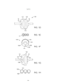
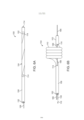
[020] A Fig. 1A ilustra um cateter que possui uma seção deformável que pode assumir uma configuração helicoidal.[020] Fig. 1A illustrates a catheter having a deformable section that can assume a helical configuration.
[021] A Fig. 1B ilustra uma força proximal aplicada a um fio de tração para fazer a seção desviável assumir um perfil em hélice ou helicoidal.[021] Fig. 1B illustrates a proximal force applied to a traction wire to make the deviated section assume a helix or helical profile.
[022] A Fig. 1C mostra uma vista em perspectiva de um cateter que está na configuração helicoidal.[022] Fig. 1C shows a perspective view of a catheter that is in the helical configuration.
[023] As Figs. 1D a 1H ilustram uma configuração expansível da seção desviável do cateter.[023] Figs. 1D through 1H illustrate an expandable configuration of the catheter bypass section.
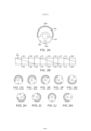
[024] As Figs. 2A a 2K mostram como uma seção transversal da seção desviável gira ao longo de um comprimento da seção desviável.[024] Figs. 2A to 2K show how a cross section of the deviate section rotates along a length of the deviate section.
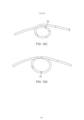
[025] As Figs. 3A a 3C ilustram variações adicionais dos formatos helicoidais para uso com variações dos cateteres aqui descritos.[025] Figs. 3A through 3C illustrate additional variations of helical shapes for use with variations of the catheters described herein.
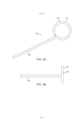
[026] As Fig. 4A a 4C mostram um cateter de volta única.[026] Figs. 4A to 4C show a single loop catheter.
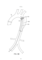
[027] As Figs. 5A a 5C mostram um exemplo de um cateter com uma seção deformável sendo usado para instalar um dispositivo médico em um lúmen corporal.[027] Figs. 5A to 5C show an example of a catheter with a deformable section being used to install a medical device into a body lumen.
[028] As Figs. 6A e 6B mostram uma variação do dispositivo onde um lúmen do fio guia existe em uma lateral da seção desviável e insere novamente o dispositivo em uma seção distal.[028] Figs. 6A and 6B show a variation of the device where a guide wire lumen exists on one side of the bypass section and reinserts the device into a distal section.
[029] As Figs. 7A e 7B mostram outra variação de um dispositivo que possui um atuador que permite a expansão da seção desviável conforme ela forma as voltas helicoidais.[029] Figs. 7A and 7B show another variation of a device that has an actuator that allows the bypass section to expand as it forms the helical turns.
[030] As Figs. 8A a 8D ilustram variações de dispositivos que possuem lumens de liberação de fluido.[030] Figs. 8A through 8D illustrate variations of devices that have fluid delivery lumens.
[031] As Figs. 9A e 9B mostram portas no exterior da seção desviável.[031] Figs. 9A and 9B show ports on the outside of the bypass section.
[032] A Fig. 10 mostra uma variação de um dispositivo expandido em uma artéria e distribuição de um fluido.[032] Fig. 10 shows a variation of a device expanded into an artery and delivery of a fluid.
[033] As Figs 11A e 11B mostram variações adicionais do dispositivo.[033] Figs 11A and 11B show additional variations of the device.
[034] As Figs. 12A a 12D mostram uma variação de um dispositivo com um fio ou sutura adicional usado para auxiliar a seção desviável quando formar uma bobina ou hélice.[034] Figs. 12A to 12D show a variation of a device with an additional thread or suture used to assist the deviated section when forming a coil or helix.
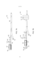
[035] As FIGS. 13A e 13B ilustram o cateter que se afasta de um local alvo e um cateter balão helicoidal melhorado, respectivamente.[035] FIGS. 13A and 13B illustrate the catheter moving away from a target site and an improved helical balloon catheter, respectively.
[036] As FIGS. 14A a 14C ilustram um exemplo de um cateter balão helicoidal configurado para aplicar compressão ou fixação a um fio guia.[036] FIGS. 14A through 14C illustrate an example of a helical balloon catheter configured to apply compression or fixation to a guidewire.
[037] As ilustrações a seguir demonstram diversas realizações e exemplos dos dispositivos e métodos de acordo com a presente revelação. As combinações de aspectos de diversos dispositivos e métodos ou combinações dos próprios dispositivos e métodos são consideradas dentro do escopo desta revelação.[037] The following illustrations demonstrate various embodiments and examples of the devices and methods according to the present disclosure. Combinations of aspects of various devices and methods or combinations of the devices and methods themselves are considered within the scope of this disclosure.
[038] A Fig. 1A ilustra uma variação de um cateter 100, de acordo com a presente revelação. A Fig. 1A representa o cateter 100 em uma configuração linear de forma geral; no entanto, o cateter 100 pode ser opcionalmente configurado como flexível para navegar através da anatomia tortuosa, como a vasculatura e/ou demais órgãos em todo o corpo. A Fig. 1A mostra o cateter, que inclui uma porção distal 102 tendo um lúmen opcional que termina em uma extremidade distal 114. O cateter 100 também inclui uma porção proximal 106 que é usada por um operador para manipular o cateter 100. As variações do cateter 100 podem incluir qualquer número de núcleos ou alças localizados em direção à extremidade proximal da porção proximal 106. O cateter 100 inclui uma seção desviável 104 localizada entre a porção proximal 106 e porção distal 102. Conforme discutido abaixo, a seção desviável 104 pode ser acionada por um usuário por meio de um fio de tração 108 ou outros meios similares. As variações do dispositivo 100 podem incluir um cateter 100 sem uma porção distal 102 ou com uma seção desviável 104, que se estende ao longo de um comprimento significativo do cateter 100. A seção desviável 104, conforme descrito detalhadamente abaixo, inclui uma seção transversal que gira ao longo de um comprimento da seção desviável 104 e conforme representado por 118. A seção transversal girada compreende pelo menos dois materiais diferentes que se estendem helicoidalmente ao longo de um comprimento da seção desviável 104.[038] Fig. 1A illustrates a variation of a
[039] A Fig. 1B ilustra uma força proximal 116 aplicada ao fio de tração 108 para fazer com que a seção desviável 104 assume um perfil de hélice ou helicoidal 110. A seção transversal girada da seção desviável 104 resulta no desvio helicoidal da seção desviável 104 mediante aplicação de uma força de tensão sobre o fio de tração 108, que se estende através de pelo menos uma porção da seção desviável. A variação ilustrada na Fig. 1B demonstra um formato helicoidal 100 que possui 4 voltas 112. No entanto, os dispositivos e métodos aqui descritos podem incluir qualquer número de voltas 112, bem como configurações helicoidais alternativas, conforme mostrado abaixo.[039] Fig. 1B illustrates a
[040] A Fig. 1C mostra uma vista em perspectiva de um cateter 100 que possui uma seção desviável 104 em um perfil helicoidal, conforme mostrado, o perfil helicoidal 110 inclui uma passagem 120 que evita que o cateter 100 oclua o lúmen corporal quando em uma configuração helicoidal.[040] Fig. 1C shows a perspective view of a
[041] A Fig. 1D ilustra outra variação de um cateter 100 na presente revelação. Nesta variação, a seção desviável 104 do cateter 100 pode se expandir. A Fig. 1E ilustra uma vista transversal tomada ao longo da linha 1E-1E na Fig. 1D. A Fig. 1F ilustra uma vista ampliada da volta mais à esquerda 112 do perfil helicoidal. Conforme mostrado, o cateter 100 pode incluir um lúmen de inflação 150, um lúmen de fio guia 152 em um fio de tração 154 ou lúmen de fio de tração 154. Uma variação do dispositivo inclui um lúmen de inflação 150 que está ligado por um material expansível 156 e um material flexível 158. O material flexível permite a flexão seletiva da seção deformável 104 enquanto o material expansível 156 expande sob pressurização do lúmen de inflação 150. Em tais determinadas variações, o material elástico 156 é orientado de modo que o material 156 se expanda para fora da forma helicoidal enquanto mantém a passagem 120 de modo que o fluxo permaneça através do órgão ou lúmen corporal.[041] Fig. 1D illustrates another variation of a
[042] O material elástico pode compreender um material comumente usado no balão elástico médico. Os exemplos de materiais para o material de suporte/elástico podem incluir Pebax ou uma mistura de Pebax e siloxano. O material elástico pode ser coextrudido com o material flexível. Além disso, as variações do dispositivo podem incluir uma porção proximal que compreende um material mais rígido que o material flexível usado na seção desviável.[042] The elastic material may comprise a material commonly used in the medical elastic balloon. Examples of materials for the support/elastic material could include Pebax or a mixture of Pebax and siloxane. The elastic material can be co-extruded with the flexible material. In addition, device variations may include a proximal portion comprising a more rigid material than the flexible material used in the bypass section.
[043] Além disso, em determinadas variações, o dispositivo pode se enrolar automaticamente sem a necessidade de um fio de tração separado devido a uma seleção específica de materiais. Por exemplo, em tal variação, o material balão expansível elástico é coextrudido ou, de outro modo, ligado a um material não elástico do cateter e os dois materiais terão uma rigidez diferente e curvas de tensão de rigidez e alongamento. Em tal variação, na inflação da porção elástica do tubo, uma vez que o comprimento muda apenas em uma parede do tubo, a outra parede é pressionada pelo material menos elástico. Isto resulta no segmento do balão do cateter que forma automaticamente uma configuração helicoidal enrolada na expansão. O diâmetro do balão e o diâmetro da configuração de balão helicoidal inflado podem ser predeterminados pela seleção dos parâmetros de desenho adequados, inclusive a seleção de material, rigidez, comprimento e perfis de seção transversal de extrusão.[043] In addition, in certain variations, the device can automatically wind itself without the need for a separate traction wire due to a specific selection of materials. For example, in such a variation, the elastic expandable balloon material is co-extruded or otherwise bonded to an inelastic catheter material and the two materials will have different stiffness and stress curves of stiffness and elongation. In such a variation, on inflation of the elastic portion of the tube, since the length changes only on one wall of the tube, the other wall is pressed by the less elastic material. This results in the catheter balloon segment automatically forming a coiled helical configuration on expansion. The diameter of the balloon and the diameter of the inflated helical balloon configuration can be predetermined by selecting the appropriate design parameters, including material selection, stiffness, length, and extrusion cross-section profiles.
[044] A Fig. 1G ilustra a expansão ao longo da seção deformável 104 ao expandir o material elástico 156 em uma direção distante do formato helicoidal. Conforme mostrado, o material flexível 158 permite a formação do formato helicoidal, mas evita a oclusão da passagem 120.[044] Fig. 1G illustrates expansion along the
[045] A Fig. 1H mostra uma vista transversal tomada ao longo da linha 1H-1H na Fig. 1G. Conforme mostrado, o material elástico 156 se expande para longe da hélice porque o lúmen de inflação é pressurizado (por meio de um fluido ou um gás). A Fig. 1H também ilustra o material elástico 158, como permissão para a deformação da seção desviável 104, mas também provê um suporte o material flexível 156 se expandir.[045] Fig. 1H shows a cross-sectional view taken along
[046] A Fig. 2A ilustra uma seção transversal da seção deformável 104, conforme mostrado na Fig. 1F. Novamente, o lúmen de inflação 150 está ligado por um material expansível 156 e o material flexível 158. O material flexível permite a flexão seletiva da seção deformável 104, enquanto o material expansível 156 se expande sob pressurização do lúmen de inflação 150. Novamente, o material elástico 156 pode ser orientado de modo que o material 156 se expanda para fora a partir do formato helicoidal, enquanto mantém a passagem 120 de modo que o fluxo permanece através do órgão ou lúmen corporal.[046] Fig. 2A illustrates a cross-section of the
[047] Em um exemplo, a porção não expansível do dispositivo pode ser fabricada de Peba, Poliuretano, Nylon ou uma ligação de Poliuretano e Siloxano, ou Peba e Siloxano, ou Nylon e Siloxano. Nas variações que compreendem Peba e Siloxano, ou Poliuretano e Siloxano, ou Nylon e Siloxano, a extrusão é processada de modo que o Siloxano é dispersado uniformemente através do outro material. Por ter o dispêndio uniforme, Siloxano permite a lubrificação uniforme elevada em toda a extrusão. As variações alternativas incluem um dispositivo fabricado a partir de qualquer material comumente conhecido usado nas aplicações de dispositivo médico.[047] In one example, the non-expandable portion of the device can be manufactured from Peba, Polyurethane, Nylon or a bond of Polyurethane and Siloxane, or Peba and Siloxane, or Nylon and Siloxane. In variations comprising Peba and Siloxane, or Polyurethane and Siloxane, or Nylon and Siloxane, the extrusion is processed such that the Siloxane is evenly dispersed throughout the other material. By having uniform output, Siloxane allows for high uniform lubrication throughout the extrusion. Alternative variations include a device fabricated from any commonly known material used in medical device applications.
[048] A Fig. 2B mostra uma vista parcial de uma seção deformável 104 para ilustrar a rotação da seção transversal da seção deformável 104. A Fig. 2B mostra diversas seções transversais tomadas ao longo das linhas 2C/2C a 2K/2K. Conforme mostrado, a seção transversal gira ao longo de um comprimento da seção desviável 104, de modo que diferentes materiais que formam a seção transversal girem helicoidalmente ao longo da porção desviada 104. A velocidade de rotação e/ou o comprimento sobre o qual a seção transversal gira pode ser escolhido de forma seletiva para produzir as características exigidas para a aplicação em particular.[048] Fig. 2B shows a partial view of a
[049] As Figs. 3A a 3C ilustram variações do formato helicoidal 110 de diversas seções desviáveis 104. A Fig. 3A ilustra um formato helicoidal que possui um diâmetro uniforme 170, 172 entre as voltas da hélice, bem como uma elevação uniforme 174. A Fig. 3B ilustra um diâmetro variável. Neste exemplo, o diâmetro 174 diminui em uma direção distal, de modo que a volta distal possua um diâmetro menor 176 que a volta proximal. A Fig. 3C ilustra um formato helicoidal que possui elevação variável, conforme medido pelas distâncias 178, 180, 182. Conforme mostrado, a elevação se expande em uma direção distal. No entanto, a elevação pode se expandir em uma direção proximal também.[049] Figs. 3A-3C illustrate variations of the
[050] A Fig. 4A ilustra uma variação de um cateter 100 que possui uma única volta helicoidal 112. A Fig. 4B ilustra uma vista lateral do cateter 100 da Fig. 4A. A Fig. 4C mostra a variação da Fig. 4A mediante expansão do material elástico 156 enquanto o material flexível 158 se deforma para formar a volta 112 e prover suporte para formar a passagem 120. A Fig. 4C também mostra um fio guia 188 que é avançado através de um lúmen do fio guia.[050] Fig. 4A illustrates a variation of a
[051] As Figs. 5A a 5C ilustram um exemplo de um método de uso de um cateter 100, conforme descrito aqui. Conforme mostrado na Fig. 5A, um cateter 100 é avançado através de um vaso 10 ou órgão (nesta variação, o vaso compreende um arco aórtico). No entanto, o cateter 100 pode ser dimensionado para se ajustar a diversos órgãos ou vasos no corpo. O cateter 100 pode ser usado opcionalmente para expandir um implante 200 dentro do vaso 10. Alternativamente, o cateter 100 pode ser usado isoladamente para prover uma força de expansão contra o órgão ou vaso. A Fig. 5B ilustra a transformação da seção desviável 104 do cateter 100 em uma hélice. Conforme mostrado, isto pode expandir parcialmente, de forma opcional, o implante 202 para posicionamento ou implantação parcial. A Fig. 5C mostra a expansão do material elástico para implantação total do implante 202. Conforme descrito acima, o fluxo continua no vaso 10 devido à passagem no formato helicoidal.[051] Figs. 5A-5C illustrate an example of a method of using a
[052] A Fig. 6A mostra uma variação de um dispositivo que possui um lúmen de fio guia 152 que se estende através do dispositivo e possui diversas aberturas 114 para permitir que um fio guia passe fora da seção desviável 104 e então reentre no dispositivo 100 em uma abertura 114 na porção distal 102 de modo que o fio guia possa atravessar uma abertura de fio guia distal 114. Conforme mostrado, o lúmen do fio guia 152 pode se estender adjacente a um fio de tração 108 ou outro meio similar na porção proximal 106 do dispositivo 100. No entanto, na seção desviável 104 ou próximo a ela, o lúmen do fio guia sai do dispositivo 100 na abertura 114 de modo que o fio guia possa sair do dispositivo ao longo da seção desviável 104 e então reentra no dispositivo em uma segunda abertura 114 adjacente à porção distal 102 do dispositivo. Esta configuração permite que o fio guia se estenda para fora da abertura mais distal 114.[052] Fig. 6A shows a variation of a device that has a
[053] A Fig. 6B ilustra um fio guia 188 que se estende através do dispositivo 100, mas atravessa as voltas helicoidais 110. O fio guia 188 então reentra na porção distal 102 do dispositivo 100 de modo que um médico possa navegar a porção distal 102 do dispositivo 100 usando o fio guia 188.[053] Fig. 6B illustrates a
[054] As Figs. 7A e 7B mostram outra variação de um dispositivo 100 que possui um atuador 194 que permite a expansão da seção desviável 104 conforme ela forma voltas helicoidais 112. A Fig. 7A mostra o dispositivo 100 em uma configuração linear onde um fio de tração 108 que se estende através da seção desviável 104 também se estende proximalmente e é acoplado ao atuador 192. Nesta variação, o fio de tração 108 é acoplado a um pistão 194 no atuador 192. O atuador 129 também é acoplado a uma válvula 190 (nesta variação, a válvula é uma válvula de três formas). A válvula também é acoplada a uma fixação 186 do dispositivo 100. Observa-se que o fio de tração 108 pode ser separado do fio guia, que é inserido através do lúmen do fio guia 152.[054] Figs. 7A and 7B show another variation of a
[055] A Fig. 7B representa uma fonte de fluido que é acionada através da válvula 190, conforme representado pela seta 210. O fluido 210 viaja através do dispositivo 100, conforme mostrado pela seta 212, para expandir a área expansível conforme discutido acima. No entanto, a válvula de três vias 190 também faz com que o fluido pressurize o atuador 192 para acionar o pistão 194 fora do atuador 192. Como o pistão 194 está acoplado ao fio de tração 108, o movimento do pistão 194 causa movimento proximal do fio de tração, conforme observado pela seta 216. O movimento do fio de tração faz com que as voltas 112 da seção desviável 104 formem o formato helicoidal.[055] Fig. 7B depicts a source of fluid that is actuated through
[056] As Figs. 8A a 8D ilustram outro aspecto para uso dos dispositivos aqui descritos. As figuras mostram uma seção transversal de uma seção expansível do dispositivo 100. Nesta variação, o dispositivo 100 inclui um lúmen de liberação de fluido 162 que permite a liberação de uma substância fluida do corpo principal do cateter. A Fig. 8A mostra uma variação na qual o lúmen de liberação de fluido 162 está localizado em uma parede expansível 156 do dispositivo 100. As variações alternativas permitem que o lúmen de liberação de fluido 162 seja posicionado em qualquer lugar nas paredes do dispositivo 100. A Fig. 8B ilustra uma variação do dispositivo 100 com uma pluralidade de lúmens de liberação de fluido 162. Embora não representado nas Figs. 8A a 8D, o lúmen de liberação de fluido 162 terá uma ou mais portas que depositam o fluido em um local desejado fora do corpo do dispositivo 100. A Fig. 8C mostra o dispositivo 100 em um estado expandido onde o lúmen de liberação de fluido 162 assume o formato oval sem ser ocluído. A Fig. 8D ilustra outra variação de um dispositivo 100 onde o lúmen de liberação de fluido 162 é formado por uma seção expansível 163 no exterior do cateter 100. Esta configuração permite que o lúmen de liberação de fluido grande que pode se expandir facilite a passagem de um fluido. O lúmen de liberação de fluido 162 terá uma ou mais portas de liberação de fluido (não mostrado nas Figs. 8A a 8D), que permitem a liberação do fluido quando o cateter está no formato reto e/ou enrolado.[056] Figs. 8A to 8D illustrate another aspect for using the devices described herein. The figures show a cross-section of an expandable section of the
[057] As Figs. 9A e 9B ilustram variações de um dispositivo, conforme descrito aqui, onde uma ou mais portas de fluido 128 terminam em uma superfície exterior da porção enrolada ou helicoidal do dispositivo 100. As portas 128, que estão em comunicação fluida com o lúmen de fluido, podem ser posicionadas em qualquer lado ou ambos os lados da volta helicoidal 112 da seção desviável 104. Em tal configuração, colocar as portas 128 nas laterais e/ou dentro da volta helicoidal 112 evita que a porta 128 seja bloqueada durante a expansão da seção desviável 104. A Fig. 9B ilustra outra variação de um dispositivo 100 que possui portas 128. Nesta variação, as portas 128 são posicionadas centralmente nas voltas 128 da seção desviável 104. As Figs. 9A e 9B também mostram o dispositivo 100 tendo qualquer número de núcleos 196, 198 que podem ser fluidamente acoplados ao lúmen de liberação de fluido (não mostrado) de modo que a fonte externa de fluido possa ser acoplada ao respectivo núcleo, permitindo a liberação do fluido. Em variações adicionais, as portas podem estar localizadas em portas adicionais do cateter, inclusive, entre outros, a porção não expandida do cateter.[057] Figs. 9A and 9B illustrate variations of a device as described herein, where one or more
[058] A Fig. 10 ilustra uma variação do dispositivo 100 aqui descrito posicionado em uma artéria coronária 14 em um coração 12 onde a seção desviável 104 é enrolada enquanto permite que o fluxo sanguíneo atravesse o vaso coronariano 14. O dispositivo 100 também permite a liberação de drogas, medicamentos ou outros agentes através das portas descritas acima.[058] Fig. 10 illustrates a variation of the
[059] As Figs 11A e 11B mostram variações adicionais do dispositivo onde a seção helicoidal ou desviável é unida a uma porção proximal 106 e uma porção distal 102 de modo que a seção desviável compreenda um material elástico 156 e um material flexível 158 para permitir a deformação em um formato helicoidal. Conforme mostrado, a seção desviável 104 pode selecionar de forma opcional ser um material transparente ou semitransparente.[059] Figs 11A and 11B show additional variations of the device where the helical or shiftable section is joined to a
[060] Os dispositivos descritos acima podem tratar de um problema comum quando a prática comum de uso de um fio macio ganha acesso ao local alvo e então traz um cateter guia mais favorável sobre o fio que pode levar ao fio guia. Nestes casos, o instrumento mais rígido afasta-se do local alvo desejado. Por exemplo, uma variação do dispositivo pode usar o cateter balão helicoidal rastreável de extremidade mole para rastrear facilmente o fio guia macio que foi trazido ao local alvo e então o balão externo é inflado para se acomodar à parede da artéria enquanto permite que o fluxo sanguíneo passe o dispositivo inflado para continuar a perfusão dos órgãos a jusante. Um balão interno pode ser inflado, o qual colide no ID do cateter balão helicoidal Python na porção RX da extremidade distal do cateter balão helicoidal, de modo que, quando o fio guia residir no lúmen RX, ele seja mantido fixo no lugar pelo balão interno inflado. Este efeito permite que a tração seja aplicada ao fio guia (encostar no fio guia não move a extremidade do fio guia) porque o balão externo está engatado ao ID do vaso sanguíneo ou lúmen brônquico que transfere a força de tensão à artéria, veia ou lúmen.[060] The devices described above can address a common problem when the common practice of using a soft wire gains access to the target site and then brings a more favorable guide catheter over the wire that can lead to the guide wire. In these cases, the more rigid instrument moves away from the desired target location. For example, a variation of the device could use the soft-end traceable helical balloon catheter to easily trace the soft guidewire that has been brought to the target site and then the outer balloon is inflated to accommodate the artery wall while allowing blood flow. pass the inflated device to continue perfusion of downstream organs. An inner balloon can be inflated which impinges on the ID of the Python helical balloon catheter at the RX portion of the distal end of the helical balloon catheter so that when the guide wire resides in the RX lumen it is held in place by the inner balloon inflated. This effect allows traction to be applied to the guidewire (touching the guidewire does not move the end of the guidewire) because the outer balloon is engaged to the ID of the blood vessel or bronchial lumen which transfers the tension force to the artery, vein or lumen. .
[061] As Figs. 12A a 12B mostram um exemplo de um dispositivo 100 que possui uma característica que auxilia na formação da seção desviável 104 em uma estrutura helicoidal. Como com as demais variações aqui descritas, as características e aspectos de cada exemplo aqui discutido podem ser combinados com outras variações reveladas do dispositivo onde estas características não conflitam.[061] Figs. 12A-12B show an example of a
[062] Conforme mostrado na Fig. 12A, o dispositivo 100 inclui um fio 204 (que pode ser um fio, sutura, estrutura enrolada, de filamento ou similar) que se estende de uma extremidade proximal do dispositivo 100 (por exemplo, através de um núcleo 196 conforme mostrado) para uma primeira abertura 208 que está localizada proximalmente a (ou em uma extremidade proximal) da seção desviável 104. O fio 204 se estende para fora do dispositivo ao longo de uma porção da seção desviável 104 e reentra no dispositivo 100 em um local 218 distal à (ou em uma extremidade distal da) seção desviável 104. O fio 204 pode ser fixado no local distal 218 ou pode estar livre para flutuar, contato que permaneça no dispositivo uma abertura distal 218. A FIG. 12A também ilustra esta variação do dispositivo 100 como tendo um núcleo 196 com uma característica de bloqueio 206. A característica de bloqueio 206 prende o fio 204 quando desejado. Conforme discutido abaixo, assim que a seção desviável é posicionada conforme desejado, o fio 204 pode ser bloqueado no local usando a característica de bloqueio 206 para prender o formato helicoidal da seção desviável. Em uma variação adicional, o fio 204 pode ser acoplado a um mecanismo de pistão, conforme descrito nas Figs. 7A e 7B acima.[062] As shown in Fig. 12A,
[063] A FIG. 12B ilustra a seção desviável 104 conforme ela começa a enrolar. Conforme mencionado acima, a seção desviável 104 pode estar para assumir um formato enrolado usando um fio de tração ou as características naturais dos materiais que formam o dispositivo 100. Conforme mostrado, o fio 204 permanece fora do dispositivo 100. A FIG. 12C ilustra o fio 204 sendo trazido próximo à distância entre a abertura proximal 208 e a abertura distal 218. Esta ação permite que a seção desviável 104 do dispositivo 100 forme um formato enrolado, conforme desejado. A FIG. 12D ilustra o formato helicoidal da seção deformável 104 quando o fio (não mostrado) prende a bobina helicoidal do dispositivo. Embora a variação representada nas FIGS. 12A a 12D enrole apenas uma única volta da forma helicoidal, qualquer número de fios pode ser usado para formar voltas adicionais do dispositivo. Alternativamente, um fio pode atravessar qualquer número de voltas da seção desviável 104.[063] FIG. 12B illustrates the offset
[064] Em outra variação, o dispositivo pode incluir um membro em série ou outro similar que seja anexado a uma extremidade proximal da extremidade distal e se estende através do lúmen de fio de tração que sai logo onde o primeiro ciclo do balão se inicia. Então, quando o cateter forma seu primeiro ciclo, a série retorna ao lúmen. Isto poderia ser repetido, dependendo do número de ciclos do balão. Quando o cateter está reto antes da inflação, a série é externa para poucas polegadas em um ponto ao longo do comprimento de um cateter na seção de ciclo, ou dois pontos se tiver dois ciclos. A série pode ser retirada da parte traseira manualmente ou conceito de êmbolo da seringa que é discutido acima.[064] In another variation, the device may include a serial or similar member that is attached to a proximal end of the distal end and extends through the traction wire lumen that exits just where the first balloon cycle begins. Then, when the catheter forms its first loop, the array returns to the lumen. This could be repeated depending on the number of balloon cycles. When the catheter is straight before inflation, the series is external to a few inches at one point along the length of a catheter in the loop section, or two points if it has two loops. The series can be withdrawn from the rear by hand or syringe plunger concept which is discussed above.
[065] Tal variação do dispositivo aqui descrita pode prover tração para suportar um fio guia, cateter guia ou o similar em um local distal ou remoto dentro da vasculatura ou outra anatomia tortuosa, como uma passagem brônquica. Prover suporte de tração para o instrumento permite rastrear/avançar de um dispositivo mais rígido para o instrumento que de outro modo seria possível. Por exemplo, a FIG. 13A ilustra um exemplo de um cateter convencional 140 sendo rastreado sobre um fio guia 142 através da anatomia tortuosa. Conforme observado acima, o dispositivo pode ser usado em qualquer anatomia tortuosa não limitada à vasculatura. A FIG. 13A mostra uma porção 144 do cateter/fio guia que forma uma via indesejada, conforme ilustrado pela seção inclinada. Normalmente, tal situação ocorre quando um dispositivo relativamente rígido avança sobre o fio guia ou através do cateter guia. O avanço continuo pode fazer com que o cateter 140 e/ou o fio guia 142 afaste-se do local lavo dentro do vaso. Novamente, tal situação pode ocorrer comumente ao avançar um cateter com liberação de stent ou outro instrumento/dispositivo relativamente rígido ao longo do fio guia e/ou através do cateter.[065] Such a variation of the device described herein can provide traction to support a guide wire, guide catheter or the like at a distal or remote location within the vasculature or other tortuous anatomy, such as a bronchial passage. Providing traction support for the instrument allows tracking/advancing from a more rigid device to the instrument than would otherwise be possible. For example, FIG. 13A illustrates an example of a
[066] A FIG. 13B ilustra um dispositivo 100, conforme descrito acima, onde uma porção helicoidal 110 pode ser usada para ancorar o dispositivo em um alvo adequado enquanto permite que o fluxo sanguíneo atravesse a porção helicoidal 110. Nesta variação, o dispositivo 100 é configurado para aplicar tração sobre o fio guia 188 em uma porção distal 102 do dispositivo 100. A aplicação de tração sobre o fio guia 188 permite que uma força de tensão 146 seja aplicada sobre o fio guia 188. Isto, adicionada a tensão, permite que os dispositivos relativamente rígidos sejam avançados ao longo do fio guia /dispositivo 100 (nestes casos onde o fio guia 188 avança através do dispositivo 100) sem o dispositivo mais rígido causar distorção do fio guia/cateter, conforme mostrado na FIG. 13A.[066] FIG. 13B illustrates a
[067] A FIG. 14A ilustra um exemplo de um dispositivo 100 que pode aplicar compressão a um fio guia 188, permitindo que o fio guia seja colocado em um estado de tração. A FIG. 14A ilustra um fio guia 188 que se estende através de uma porção distal 102 da seção desviável 104 do dispositivo e exterior para um excedente do dispositivo 100. No entanto, os desenhos alternativos contemplam o fio guia que se estende através de toda ou uma porção aumentada do dispositivo 100, conforme mostrado acima.[067] FIG. 14A illustrates an example of a
[068] A FIG. 14B ilustra uma vista secional transversal parcial de uma porção distal 102 da seção desviável 104 do dispositivo 100. Conforme mostrado, o fio guia 188 através de um lúmen do fio guia 114. O interior do lúmen do fio guia 114 inclui um balão expansível, bexiga ou outra estrutura expansível 126 que é fluidamente acoplada a um lúmen de expansão 126 (ou uma via elétrica condutora no caso em que a estrutura expansível 126 é eletromecânica e/ou eletricamente acionada). A FIG. 14B ilustra uma condição onde a estrutura expansível 126 está em um perfil não expandido. A FIG. 14C ilustra uma condição onde a estrutura expansível 126 é expandida para entrar no lúmen do fio guia 114 e aplicar uma força compressiva/de aperto no fio guia 188. O membro expansível 126 pode se estender, conforme mostrado na FIG. 14C. Alternativamente, o membro expansível 126 pode se estender através do comprimento do lúmen. Em outra variação, o membro expansível pode compreender uma estrutura com base em cunha que colide o fio guia em uma ou mais laterais.[068] FIG. 14B illustrates a partial cross-sectional view of a
[069] Em qualquer caso, o acionamento do membro expansível 126 evita que o fio guia se mova através do lúmen 114, o que permite que o profissional médico aplique a tensão no fio guia para colocá-lo em um estado de tração. Em determinadas variações, a porção distal 102 do dispositivo 100 pode permanecer relativamente dura ou rígida para evitar o movimento lateral do membro distal na aplicação de tensão do fio guia fixado.[069] In any case, actuation of the
[070] Basicamente, esta variação pode ajudar com o problema de perda indesejada de posição para os fios guia e cateteres que estão localizados em alvos dentro da anatomia vascular, tronco brônquico ou outra tortuosa. Estes dispositivos servem como um guia para rastrear outros dispositivos terapêuticos ou diagnósticos ao local alvo sobre o fio guia ou através do cateter guia. Normalmente, um fio guia de extremidade macia é acionado primeiro para o local alvo a partir de um ponto de acesso remoto e sua flexibilidade distal e rigidez proximal permite a navegação em curvas e ainda permite reverter a direção como quando um fio guia ou cateter entra no corpo no local da artéria femoral e é colocado em uma artéria inominada que se estende a partir de um arco aórtico tipo III. Esta consideração anatômica é um prognosticador da dificuldade de inserção de stent na carótida, conforme é bem conhecido pelo perito na técnica.[070] Basically, this variation can help with the problem of unwanted loss of position for guidewires and catheters that are located on targets within the vascular, bronchial trunk, or other tortuous anatomy. These devices serve as a guide to track other therapeutic or diagnostic devices to the target location over the guidewire or through the guide catheter. Typically, a soft-tipped guidewire is first driven to the target site from a remote access point, and its distal flexibility and proximal rigidity allows for navigation in curves and even allows reversal of direction such as when a guidewire or catheter enters the body at the site of the femoral artery and is placed in an innominate artery extending from a type III aortic arch. This anatomical consideration is a predictor of difficulty in carotid stent insertion, as is well known to one skilled in the art.
Claims (16)

Applications Claiming Priority (3)
| Application Number | Priority Date | Filing Date | Title |
|---|---|---|---|
| US201461979991P | 2014-04-15 | 2014-04-15 | |
| US61/979,991 | 2014-04-15 | ||
| PCT/US2015/026003 WO2015160972A1 (en) | 2014-04-15 | 2015-04-15 | Helical balloon catheter |
Publications (2)
| Publication Number | Publication Date |
|---|---|
| BR112016024049A2 BR112016024049A2 (en) | 2017-08-15 |
| BR112016024049B1 true BR112016024049B1 (en) | 2023-04-25 |
Family
ID=54324545
Family Applications (1)
| Application Number | Title | Priority Date | Filing Date |
|---|---|---|---|
| BR112016024049-9A BR112016024049B1 (en) | 2014-04-15 | 2015-04-15 | CATHETER FOR USE WITH A GUIDEWIRE |
Country Status (5)
| Country | Link |
|---|---|
| US (3) | US10751515B2 (en) |
| EP (1) | EP3131616B1 (en) |
| JP (2) | JP6980386B2 (en) |
| BR (1) | BR112016024049B1 (en) |
| WO (1) | WO2015160972A1 (en) |
Families Citing this family (14)
| Publication number | Priority date | Publication date | Assignee | Title |
|---|---|---|---|---|
| EP3131616B1 (en) | 2014-04-15 | 2019-11-20 | QMax, LLC | Helical balloon catheter |
| EP3113679B1 (en) | 2014-05-06 | 2019-09-25 | St. Jude Medical, Cardiology Division, Inc. | Electrode support structure assembly |
| US10118022B2 (en) | 2014-06-05 | 2018-11-06 | St. Jude Medical, Cardiology Division, Inc. | Deflectable catheter shaft section |
| US9844645B2 (en) | 2014-06-17 | 2017-12-19 | St. Jude Medical, Cardiology Division, Inc. | Triple coil catheter support |
| KR101665615B1 (en) * | 2015-04-20 | 2016-10-12 | 국립암센터 | Apparatus for in-vivo dosimetry in radiotherapy |
| US10602983B2 (en) | 2015-05-08 | 2020-03-31 | St. Jude Medical International Holding S.À R.L. | Integrated sensors for medical devices and method of making integrated sensors for medical devices |
| JP6445742B1 (en) | 2015-10-21 | 2018-12-26 | セント・ジュード・メディカル,カーディオロジー・ディヴィジョン,インコーポレイテッド | High density electrode mapping catheter |
| WO2018080985A1 (en) | 2016-10-24 | 2018-05-03 | St. Jude Medical, Cardiology Division, Inc. | Catheter insertion devices |
| US11647935B2 (en) | 2017-07-24 | 2023-05-16 | St. Jude Medical, Cardiology Division, Inc. | Masked ring electrodes |
| EP4115936B1 (en) | 2017-11-28 | 2024-03-06 | St. Jude Medical, Cardiology Division, Inc. | Lumen management catheter |
| US11076973B2 (en) * | 2018-04-10 | 2021-08-03 | Spica Medical Technologies Llc | Intragastric helical prosthesis for treating obesity |
| EP3809962A2 (en) | 2018-08-23 | 2021-04-28 | St. Jude Medical, Cardiology Division, Inc. | Curved high density electrode mapping catheter |
| US11918762B2 (en) | 2018-10-03 | 2024-03-05 | St. Jude Medical, Cardiology Division, Inc. | Reduced actuation force electrophysiology catheter handle |
| CN113384319B (en) * | 2021-06-02 | 2023-04-25 | 上海腾复医疗科技有限公司 | Catheter |
Family Cites Families (29)
| Publication number | Priority date | Publication date | Assignee | Title |
|---|---|---|---|---|
| US4932959A (en) | 1988-12-01 | 1990-06-12 | Advanced Cardiovascular Systems, Inc. | Vascular catheter with releasably secured guidewire |
| US5035705A (en) | 1989-01-13 | 1991-07-30 | Scimed Life Systems, Inc. | Method of purging a balloon catheter |
| US5454789A (en) * | 1989-01-13 | 1995-10-03 | Scimed Life Systems, Inc. | Innerless dilatation balloon catheter |
| US5221260A (en) | 1989-01-13 | 1993-06-22 | Scimed Life Systems, Inc. | Innerless dilatation balloon catheter |
| AU6375590A (en) | 1989-10-03 | 1991-04-11 | C.R. Bard Inc. | Multilumen catheter with variable cross-section lumens |
| WO1992019311A1 (en) * | 1991-04-24 | 1992-11-12 | Baxter International Inc. | Exchangeable integrated-wire balloon catheter |
| US5226888A (en) * | 1991-10-25 | 1993-07-13 | Michelle Arney | Coiled, perfusion balloon catheter |
| US5299575A (en) | 1992-07-23 | 1994-04-05 | Sandridge James B | Short exchange guiding catheter apparatus and method |
| JPH11169464A (en) * | 1997-12-09 | 1999-06-29 | Emiko Yunoki | Catheter |
| US6183491B1 (en) * | 1998-03-10 | 2001-02-06 | Cordis Corporation | Embolic coil deployment system with improved embolic coil |
| US6231543B1 (en) * | 1999-04-15 | 2001-05-15 | Intella Interventional Systems, Inc. | Single lumen balloon catheter |
| US6482221B1 (en) * | 2000-08-21 | 2002-11-19 | Counter Clockwise, Inc. | Manipulatable delivery catheter for occlusive devices (II) |
| US6890343B2 (en) * | 2000-12-14 | 2005-05-10 | Ensure Medical, Inc. | Plug with detachable guidewire element and methods for use |
| US6896692B2 (en) * | 2000-12-14 | 2005-05-24 | Ensure Medical, Inc. | Plug with collet and apparatus and method for delivering such plugs |
| US6679860B2 (en) * | 2001-06-19 | 2004-01-20 | Medtronic Ave, Inc. | Intraluminal therapy catheter with inflatable helical member and methods of use |
| US6786886B2 (en) | 2001-08-03 | 2004-09-07 | Scimed Life Systems, Inc. | Method for stabilizing balloon during dilation |
| US20040039372A1 (en) | 2002-08-21 | 2004-02-26 | Carmody Patrick J. | Over-the-wire catheter having a slidable instrument for gripping a guidewire |
| US8920432B2 (en) * | 2002-09-24 | 2014-12-30 | Medtronic, Inc. | Lead delivery device and method |
| US6923808B2 (en) * | 2003-02-24 | 2005-08-02 | Boston Scientific Scimed, Inc. | Probes having helical and loop shaped inflatable therapeutic elements |
| US20090264770A1 (en) | 2008-04-17 | 2009-10-22 | Omnisonics Medical Technologies, Inc. | Medical Systems and Related Methods |
| AU2009290834B2 (en) * | 2008-09-15 | 2015-08-20 | Aeeg Ab | Medical device, method and system for temporary occlusion of an opening in a lumen of a body |
| DE102010008244A1 (en) | 2010-02-17 | 2011-08-18 | Andreas Stihl AG & Co. KG, 71336 | Centrifugally operated coupling device |
| US8814775B2 (en) * | 2010-03-18 | 2014-08-26 | Cianna Medical, Inc. | Expandable brachytherapy apparatus and methods for using them |
| US8956352B2 (en) * | 2010-10-25 | 2015-02-17 | Medtronic Ardian Luxembourg S.A.R.L. | Catheter apparatuses having multi-electrode arrays for renal neuromodulation and associated systems and methods |
| US8702678B2 (en) | 2011-08-03 | 2014-04-22 | Venous Therapy, Inc. | Assemblies, systems, and methods for infusing therapeutic agents into the body |
| BR112015007420B1 (en) * | 2012-10-01 | 2021-06-22 | Qmax, Llc | CATHETER |
| EP3623002A1 (en) * | 2013-01-15 | 2020-03-18 | A.V. Medical Technologies, Ltd. | A catheter |
| EP3131616B1 (en) | 2014-04-15 | 2019-11-20 | QMax, LLC | Helical balloon catheter |
| US10159819B2 (en) * | 2014-04-24 | 2018-12-25 | Medtronic Vascular Galway | Control module for delivery systems |
-
2015
- 2015-04-15 EP EP15780036.8A patent/EP3131616B1/en active Active
- 2015-04-15 WO PCT/US2015/026003 patent/WO2015160972A1/en active Application Filing
- 2015-04-15 US US15/574,112 patent/US10751515B2/en active Active
- 2015-04-15 JP JP2016562235A patent/JP6980386B2/en active Active
- 2015-04-15 BR BR112016024049-9A patent/BR112016024049B1/en active IP Right Grant
-
2020
- 2020-07-20 US US16/933,571 patent/US11707607B2/en active Active
- 2020-07-22 JP JP2020125647A patent/JP7355715B2/en active Active
-
2023
- 2023-07-21 US US18/356,981 patent/US20240050713A1/en active Pending
Also Published As
| Publication number | Publication date |
|---|---|
| JP6980386B2 (en) | 2021-12-15 |
| JP7355715B2 (en) | 2023-10-03 |
| JP2020185410A (en) | 2020-11-19 |
| BR112016024049A2 (en) | 2017-08-15 |
| EP3131616B1 (en) | 2019-11-20 |
| US20180344989A1 (en) | 2018-12-06 |
| US20200384244A1 (en) | 2020-12-10 |
| US20240050713A1 (en) | 2024-02-15 |
| EP3131616A1 (en) | 2017-02-22 |
| WO2015160972A1 (en) | 2015-10-22 |
| US11707607B2 (en) | 2023-07-25 |
| JP2017512108A (en) | 2017-05-18 |
| EP3131616A4 (en) | 2017-11-29 |
| US10751515B2 (en) | 2020-08-25 |
Similar Documents
| Publication | Publication Date | Title |
|---|---|---|
| BR112016024049B1 (en) | CATHETER FOR USE WITH A GUIDEWIRE | |
| US20220257906A1 (en) | Helical balloon catheter | |
| KR101910207B1 (en) | Trimmable catheter including distal portion stability features | |
| JP6343009B2 (en) | Low profile occlusion catheter | |
| US5181911A (en) | Helical balloon perfusion angioplasty catheter | |
| US7993303B2 (en) | Stiffening support catheter and methods for using the same | |
| US11173281B2 (en) | Fenestration devices, systems, and methods | |
| JP2020512920A (en) | Urethral device | |
| JP2011505916A (en) | Drug delivery catheter having an inflatable communication portion between two axially spaced balloons | |
| US20030171642A1 (en) | Intra-aortic balloon catheter having a releasable guide wire | |
| US20180256861A1 (en) | Guidewires with Variable Rigidity | |
| JP5651257B2 (en) | Catheter-type therapeutic / diagnostic instrument with stylet and catheter tube using stylet | |
| WO2007124501A2 (en) | Stiffening support catheter |
Legal Events
| Date | Code | Title | Description |
|---|---|---|---|
| B06U | Preliminary requirement: requests with searches performed by other patent offices: procedure suspended [chapter 6.21 patent gazette] | ||
| B350 | Update of information on the portal [chapter 15.35 patent gazette] | ||
| B06A | Patent application procedure suspended [chapter 6.1 patent gazette] | ||
| B06A | Patent application procedure suspended [chapter 6.1 patent gazette] | ||
| B09A | Decision: intention to grant [chapter 9.1 patent gazette] | ||
| B16A | Patent or certificate of addition of invention granted [chapter 16.1 patent gazette] |
Free format text: PRAZO DE VALIDADE: 20 (VINTE) ANOS CONTADOS A PARTIR DE 15/04/2015, OBSERVADAS AS CONDICOES LEGAIS |