EP3113679B1 - Electrode support structure assembly - Google Patents
Electrode support structure assembly Download PDFInfo
- Publication number
- EP3113679B1 EP3113679B1 EP15721978.3A EP15721978A EP3113679B1 EP 3113679 B1 EP3113679 B1 EP 3113679B1 EP 15721978 A EP15721978 A EP 15721978A EP 3113679 B1 EP3113679 B1 EP 3113679B1
- Authority
- EP
- European Patent Office
- Prior art keywords
- support member
- distal
- assembly
- plug
- proximal
- Prior art date
- Legal status (The legal status is an assumption and is not a legal conclusion. Google has not performed a legal analysis and makes no representation as to the accuracy of the status listed.)
- Active
Links
Images


Classifications
-
- A—HUMAN NECESSITIES
- A61—MEDICAL OR VETERINARY SCIENCE; HYGIENE
- A61B—DIAGNOSIS; SURGERY; IDENTIFICATION
- A61B5/00—Measuring for diagnostic purposes; Identification of persons
- A61B5/68—Arrangements of detecting, measuring or recording means, e.g. sensors, in relation to patient
- A61B5/6846—Arrangements of detecting, measuring or recording means, e.g. sensors, in relation to patient specially adapted to be brought in contact with an internal body part, i.e. invasive
- A61B5/6847—Arrangements of detecting, measuring or recording means, e.g. sensors, in relation to patient specially adapted to be brought in contact with an internal body part, i.e. invasive mounted on an invasive device
- A61B5/6852—Catheters
- A61B5/6858—Catheters with a distal basket, e.g. expandable basket
-
- A—HUMAN NECESSITIES
- A61—MEDICAL OR VETERINARY SCIENCE; HYGIENE
- A61B—DIAGNOSIS; SURGERY; IDENTIFICATION
- A61B17/00—Surgical instruments, devices or methods, e.g. tourniquets
- A61B17/22—Implements for squeezing-off ulcers or the like on the inside of inner organs of the body; Implements for scraping-out cavities of body organs, e.g. bones; Calculus removers; Calculus smashing apparatus; Apparatus for removing obstructions in blood vessels, not otherwise provided for
- A61B17/221—Gripping devices in the form of loops or baskets for gripping calculi or similar types of obstructions
-
- A—HUMAN NECESSITIES
- A61—MEDICAL OR VETERINARY SCIENCE; HYGIENE
- A61B—DIAGNOSIS; SURGERY; IDENTIFICATION
- A61B18/00—Surgical instruments, devices or methods for transferring non-mechanical forms of energy to or from the body
- A61B18/04—Surgical instruments, devices or methods for transferring non-mechanical forms of energy to or from the body by heating
- A61B18/12—Surgical instruments, devices or methods for transferring non-mechanical forms of energy to or from the body by heating by passing a current through the tissue to be heated, e.g. high-frequency current
- A61B18/14—Probes or electrodes therefor
- A61B18/1492—Probes or electrodes therefor having a flexible, catheter-like structure, e.g. for heart ablation
-
- A—HUMAN NECESSITIES
- A61—MEDICAL OR VETERINARY SCIENCE; HYGIENE
- A61B—DIAGNOSIS; SURGERY; IDENTIFICATION
- A61B5/00—Measuring for diagnostic purposes; Identification of persons
- A61B5/24—Detecting, measuring or recording bioelectric or biomagnetic signals of the body or parts thereof
- A61B5/25—Bioelectric electrodes therefor
- A61B5/279—Bioelectric electrodes therefor specially adapted for particular uses
- A61B5/28—Bioelectric electrodes therefor specially adapted for particular uses for electrocardiography [ECG]
- A61B5/283—Invasive
- A61B5/287—Holders for multiple electrodes, e.g. electrode catheters for electrophysiological study [EPS]
-
- A—HUMAN NECESSITIES
- A61—MEDICAL OR VETERINARY SCIENCE; HYGIENE
- A61B—DIAGNOSIS; SURGERY; IDENTIFICATION
- A61B18/00—Surgical instruments, devices or methods for transferring non-mechanical forms of energy to or from the body
- A61B2018/00005—Cooling or heating of the probe or tissue immediately surrounding the probe
- A61B2018/00011—Cooling or heating of the probe or tissue immediately surrounding the probe with fluids
- A61B2018/00029—Cooling or heating of the probe or tissue immediately surrounding the probe with fluids open
-
- A—HUMAN NECESSITIES
- A61—MEDICAL OR VETERINARY SCIENCE; HYGIENE
- A61B—DIAGNOSIS; SURGERY; IDENTIFICATION
- A61B18/00—Surgical instruments, devices or methods for transferring non-mechanical forms of energy to or from the body
- A61B2018/00053—Mechanical features of the instrument of device
- A61B2018/00214—Expandable means emitting energy, e.g. by elements carried thereon
- A61B2018/00267—Expandable means emitting energy, e.g. by elements carried thereon having a basket shaped structure
-
- A—HUMAN NECESSITIES
- A61—MEDICAL OR VETERINARY SCIENCE; HYGIENE
- A61B—DIAGNOSIS; SURGERY; IDENTIFICATION
- A61B18/00—Surgical instruments, devices or methods for transferring non-mechanical forms of energy to or from the body
- A61B2018/00315—Surgical instruments, devices or methods for transferring non-mechanical forms of energy to or from the body for treatment of particular body parts
- A61B2018/00345—Vascular system
- A61B2018/00404—Blood vessels other than those in or around the heart
-
- A—HUMAN NECESSITIES
- A61—MEDICAL OR VETERINARY SCIENCE; HYGIENE
- A61B—DIAGNOSIS; SURGERY; IDENTIFICATION
- A61B18/00—Surgical instruments, devices or methods for transferring non-mechanical forms of energy to or from the body
- A61B2018/00571—Surgical instruments, devices or methods for transferring non-mechanical forms of energy to or from the body for achieving a particular surgical effect
- A61B2018/00577—Ablation
-
- A—HUMAN NECESSITIES
- A61—MEDICAL OR VETERINARY SCIENCE; HYGIENE
- A61B—DIAGNOSIS; SURGERY; IDENTIFICATION
- A61B2218/00—Details of surgical instruments, devices or methods for transferring non-mechanical forms of energy to or from the body
- A61B2218/001—Details of surgical instruments, devices or methods for transferring non-mechanical forms of energy to or from the body having means for irrigation and/or aspiration of substances to and/or from the surgical site
- A61B2218/002—Irrigation
Definitions
- This disclosure relates generally to an electrode support structure assembly.
- the instant disclosure relates to an electrode support structure assembly for basket catheters including a plurality of arms.
- Electrophysiology catheters are used in a variety of diagnostic, therapeutic, and/or mapping and ablative procedures to diagnose and/or correct conditions such as atrial arrhythmias, including for example, ectopic atrial tachycardia, atrial fibrillation, and atrial flutter.
- Arrhythmias can create a variety of conditions including irregular heart rates, loss of synchronous atrioventricular contractions, and stasis of blood flow in a chamber of a heart which can lead to a variety of symptomatic and asymptomatic ailments and even death.
- a catheter is deployed and manipulated through a patient's vasculature to the intended site, for example, a site within a patient's heart or a chamber or vein thereof.
- the catheter carries one or more electrodes that can be used for cardiac mapping or diagnosis, ablation and/or other therapy delivery modes, or both, for example.
- treatment can include, for example, radio frequency (RF) ablation, cryoablation, laser ablation, chemical ablation, high-intensity focused ultrasound-based ablation, microwave ablation, and/or other ablation treatments.
- RF radio frequency
- cryoablation laser ablation
- chemical ablation high-intensity focused ultrasound-based ablation
- microwave ablation microwave ablation
- the catheter imparts ablative energy to cardiac tissue to create one or more lesions in the cardiac tissue and oftentimes a contiguous or linear and transmural lesion. This lesion disrupts undesirable cardiac activation pathways and thereby limits, corrals, or prevents errant conduction signals that can form the basis for ar
- catheters having basket-shaped electrode support structures are generally described in, for example and without limitation, U.S. Patent No. 5,772,590 .
- catheters having basket-shaped electrode support structures are introduced through a guiding sheath with the electrode support structure in a folded or collapsed position within the sheath so that the electrode support structure does not damage tissue during its introduction.
- the guiding sheath can be removed and/or the catheter extended therefrom and the electrode support structure can be allowed to radially outwardly expand for cardiac mapping or diagnosis, ablation, and/or other therapy delivery modes, or both, for example.
- basket-shaped electrode support structures comprise a plurality of arms that can be formed from laser-cut tubing and be integral at one end or that comprise discrete, separate elements.
- the distal ends of each of these plurality of arms generally must be joined together.
- the distal ends of each of the plurality of arms can be mounted around a first piece of tubing and then be held in place by a second piece of tubing as generally described and illustrated in U.S. Patent No. 7,522,950 .
- each of the arms may be joined in such a way that the arms are configured to straighten evenly when the electrode support structure is collapsed.
- it may be difficult for the electrode support structure to collapse evenly if manufacturing variances have resulted in differences in the individual lengths of the arms.
- It may also be difficult for the electrode support structure to collapse evenly if one or more of the arms have experienced a change in length relative to the remainder of the arms, such as during manipulation of the electrode support structure around a curve, for example. If the arms do not straighten evenly when the electrode support structure is collapsed, a protrusion or "loop" can form at the distal end of one or more of the plurality of arms.
- electrode distribution may not be uniform in accordance with some electrode arrangements.
- some electrode arrangements may possibly result in electrode-to-electrode physical contact and/or electrical short circuits, which may cause electrode wear and/or limit electrode functionality.
- some electrode arrangements may not minimize the profile of the electrode support structure during collapse of the electrode support structure, which can result in electrode damage when the electrode support structure is being delivered through the delivery sheath, especially when being delivered through a tortuously angulated pathway.
- Basket-shaped electrode support structures can include an expander having a distal end attached to a distal end of the electrode support structure.
- the expander includes a proximal end that extends out of a proximal end of a catheter or other medical device employing the electrode support structure to a control handle.
- the expander can be moved longitudinally relative to the catheter or other medical device to expand and contract the electrode support structure.
- the expander is generally coaxial with the catheter. An expander will not generally allow for free axial movement of the electrode support structure if the electrode support structure is being diametrically constrained in some way.
- various embodiments disclosed herein are directed to an electrode support structure assembly.
- An electrode support structure assembly in a body in accordance with one embodiment of the present teachings includes a plug, a cap, and a plurality of support members.
- the plug defines a longitudinal axis and is configured to connect to a fluid delivery line.
- the plug also includes a lumen configured to receive a fluid from the fluid delivery line, the lumen extending in an axial direction and comprising an axial distal end.
- the plug further includes a distal tip adjacent to the axial distal end of the lumen and comprising a first channel extending across the distal tip.
- the cap is disposed around at least a portion of the plug and includes a first wall extending in the axial direction and a plurality of apertures.
- the cap further includes a second wall extending inwardly from the first wall in a radial direction.
- the first wall and the second wall of the cap define an interior.
- Each support member of the plurality of support members comprises a distal portion.
- the distal tip of the plug and the distal portions of the plurality of support members are at least partially disposed in the interior of the cap.
- the cap is configured to constrain relative movement of the distal portions of the plurality of support members with respect to the cap, and the first channel of the plug and at least one of the plurality of support members are configured to direct a fluid outwardly in a radial direction after exiting the lumen of the plug.
- An electrode support structure assembly with a longitudinal axis, a proximal portion, and a distal portion in accordance with another embodiment of the present teachings includes a support member, a constraining ring, a torsion ring, and a retainer ring.
- the support member includes a first proximal portion extending in the axial direction and a second proximal portion generally parallel to the first proximal portion.
- the constraining ring is disposed at the proximal portion of the assembly and is configured to constrain the first and second proximal portions of the support member in the axial direction.
- the torsion ring is disposed at the proximal portion of the assembly and is configured to constrain rotation of the first and second proximal portions of support member about the longitudinal axis.
- the retainer ring partially surrounds at least one of the constraining ring and torsion ring and is configured to secure the first and second proximal portions of the support member relative to at least one of the constraining ring and torsion ring.
- an electrode support structure assembly that can include an element joining the distal end of each of the plurality of arms that is configured to provide freedom for each of the plurality of arms to move independently along an axis of the electrode support structure. This may help ensure that the arms are configured to straighten evenly when the electrode support structure is collapsed. It is also desirable to provide an electrode support structure assembly that can include an element joining the distal end of each of the plurality of arms that is configured to provide freedom for each of the plurality of arms to articulate relative to an axis of the electrode support structure such that each of the plurality of arms can be positioned at numerous angles relative to the axis of the electrode support structure in order to minimize stress imparted at the distal end of the electrode support structure during collapse and/or expansion.
- saline or an anticoagulant such as a heparinized saline solution or other fluid in a basket catheter during various medical procedures, e.g., to reduce the risk of blood clot or thrombus formation.
- One effective way to prevent blood coagulation and thrombus formation is to irrigate the electrode with heparinized saline. It is still further desirable to be able to do all of this while retaining the ability to axially move a deployment mechanism, e.g., a basket catheter, or electrode support structure itself.
- designing components of the electrode support structure assembly to fit tightly together (so as to keep the catheter footprint as small as possible) can interfere with the desire to provide unconstrained delivery of irrigation fluid.
- proximal and distal may be used throughout the specification with reference to a clinician manipulating one end of a medical device or instrument used to treat a patient.
- proximal refers to the portion of the device closest to the clinician (or to a robotic control configured to manipulate the device) and the term “distal” refers to the portion located furthest from the clinician.
- distal refers to the portion located furthest from the clinician.
- spatial terms such as “vertical,” “horizontal,” “up,” and “down” may be used herein with respect to the illustrated embodiments.
- medical devices may be used in many orientations and positions, and these terms are not intended to be limiting or absolute.
- basic is not limited to the illustrated configuration, but can include other designs such as spherical or egg-shaped designs, for example.
- FIG. 1 is a diagrammatic view of a catheter system 10 employing an electrode assembly 12' in accordance with an embodiment of the present teachings.
- Catheter system 10 includes a handle 14 and connectors 16 disposed proximal to handle 14 for making electrical connections to a visualization, navigation, and/or mapping system (not shown) such as those systems available under the brand name EnsiteTM NavXTM (aka EnsiteTM "Classic” as well as newer versions of the EnsiteTM system, denoted as EnsiteTM VelocityTM) and available from St. Jude Medical, Inc.
- Handle 14 can have a uni-directional design, a bi-directional design, or any other suitable design and be accordingly configured to steer electrode assembly 12', as discussed in more detail in commonly assigned U.S. Patent No. 8,676,290 .
- Catheter system 10 can also include an introducer 18 located distally of handle 14 that may be used to deliver an elongated catheter body 20 into the body of a patient, through a hemostasis valve of another longer introducer, for example.
- Elongated catheter body 20 can extend from introducer 18.
- Elongated catheter body 20 can comprise an elongated tubular construction having one or more lumens.
- Elongated catheter body 20 can be flexible or bendable.
- Elongated catheter body 20 can be of any suitable construction and made of any suitable material as known to those of ordinary skill in the art.
- Elongated catheter body 20 can have any outer diameter, but may generally be configured for insertion into the vascalature of a body of a patient and, in some embodiments, be less than about 8 French.
- Elongated catheter body 20 can have an outer wall of any thickness, but may generally be configured so that one or more lumens can be disposed within elongated catheter body 20 to accommodate pull wires, lead wires, sensor cables, and any other wires, cable, and/or tubes that may be needed in particular applications.
- Handle 14, connectors 16, introducer 18, and elongated catheter body 20 can be readily modified as dictated by the aesthetic or functional needs of particular applications.
- Electrode assembly 12' is configured to extend from a distal portion 22 of elongated catheter body 20. Although electrode assembly 12' is described and illustrated in connection with an intracardiac catheter system 10, electrode assembly 12' may be utilized in connection with other types of medical devices, such as for example and without limitation, stone retrieval baskets, distal protection devices, renal artery ablation devices, snares, and other retrieval devices. As discussed in further detail below in connection with Figures 3-4 , assembly 12' may be configured to support electrodes and to be radially outwardly expandable and inwardly collapsible.
- FIG. 2 is an isometric view of an electrode support structure assembly 12.
- Assembly 12 is configured to be mounted to distal portion 22 of elongated catheter body 20.
- Assembly 12 is configured to be radially outwardly expandable relative to axis 24 to an expanded arrangement as shown in Figure 2 .
- Assembly 12 defines a longitudinal axis 24 and may be configured to be radially inwardly collapsible relative to axis 24 to a collapsed arrangement.
- Assembly 12 may comprise a distal subassembly 23 which may include a plug 26 and a cap 28 disposed around a portion of plug 26. Assembly may further include support members 30a-d.
- Support members 30a-d of assembly 12 can be collapsed by an application of force, for example, by moving support members 30a-d into a sheath or introducer. Upon removal of the application force, for example, by moving support members 30a-d out of a sheath or introducer, support members 30a-d may return to the expanded arrangement.
- This expansion and collapse of assembly 12 may alternatively or additionally be achieved by using a shape memory material for support members 30a-d in accordance with some embodiments.
- the expansion and collapse of assembly 12 may be achieved by using a biasing mechanism in accordance with other embodiments.
- assembly 12 may include four support members 30a-d. Although four support members 30a-d are mentioned in detail, there may be fewer or more support members in accordance with various embodiments.
- Each of the support members 30a-d may generally be evenly spaced circumferentially around axis 24 of the assembly 12.
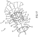
- Assembly 12 may further include a proximal subassembly 32 (best shown in Figure 17 ) to be described in more detail hereinbelow.
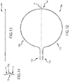
- support members 30a-d may be generally circular in shape and may each have two free ends connected to proximal subassembly 32 with distal subassembly 23 being disposed at the opposite end (see Figure 11 ).
- catheter system 10 may further include a fluid delivery line 46 in accordance with some embodiments.
- Fluid delivery line 46 may be connected to an irrigation system and include, for example and without limitation, an irrigation pump configured to supply irrigation fluid to assembly 12 and/or distal portion 22 of catheter body 20 (shown in Figure 1 ).
- an irrigation pump configured to supply irrigation fluid to assembly 12 and/or distal portion 22 of catheter body 20 (shown in Figure 1 ).
- fluid delivery line 46 when assembly 12 is expanded (as illustrated in Figure 2 ), fluid delivery line 46 may be generally arc-shaped between proximal subassembly 32 ( Figure 3 ) and distal subassembly 23. When collapsed, fluid delivery line 46 is generally straight and lies along longitudinal axis 24.
- fluid delivery line 46 allows fluid delivery line 46 to be free of any undue tension while assembly 12 is being collapsed ( e.g ., into a guiding sheath).
- the arc length of fluid delivery line 46 is approximately the same (or slightly less than) the arc length of support members 30a-d between proximal subassembly 32 ( Figure 3 ) and distal subassembly 23.
- fluid delivery line 46 may take on a number of other configurations.
- fluid delivery 46 may be generally straight when collapsed and expanded by being corrugated, functioning similarly as a spring.
- FIGs 3-4 generally illustrate electrode assembly 12' (shown generally in Figure 1 ). Assembly 12' is similar to assembly 12 of Figure 2 except that assembly 12' includes additional components. Fluid delivery line 46 has been omitted in Figure 4 for clarity.
- assembly 12' comprises arms 30', with each arm 30' comprising a support member 30a-d, a non-conductive covering 38 surrounding each support member 30a-d, and electrodes 40.
- support members 30a-d may each be a flexible wire and may be flat and/or composed of Nitinol or other like materials.
- the non-conductive covering 38 can comprise a biocompatible plastic tubing, such as polyurethane or polyimide tubing in accordance with some embodiments.
- support members 30a-d and covering 38 can be made of any other suitable materials known to those of ordinary skill in the art.
- the arms 30' can be designed without support members 30a-d if a sufficiently rigid non-conductive material is used.
- One or more of the arms 30' can have one or more electrodes 40 mounted on the non-conductive covering 38 in accordance with various embodiments.
- the number and spacing of electrodes 40 on the arms 30' can vary in accordance with various embodiments.
- the material and configuration of arms 30' (and/or support members 30a-d) can vary, as generally shown and discussed in U.S. Patent No. 8,588,885 .
- Individual components of electrode support structure assembly 12 ( Figure 2 ) will now be discussed in detail. A discussion of how the components interact and couple together will follow.
- FIGS 5A-8 illustrate various views of plug 26 of electrode support structure assembly 12 shown in Figure 2 .
- plug 26 has a proximal portion 42 and a distal portion 44.
- plug 26 comprises a connector portion 48 configured to connect to fluid delivery line 46 (connection best seen in Figure 26 ).
- connector portion 48 may be generally cylindrical about longitudinal axis 24 and include a barb 56 and a proximal end 58.
- Barb 56 is configured to secure fluid delivery line 46 in place.
- an adhesive may also be used to secure fluid delivery line 46 in place.
- plug 26 is configured to control the directional flow of the fluid when assembled with other components described herein.
- plug 26 further includes a lumen 52 generally disposed along longitudinal axis 24 extending between proximal portion 42 and distal portion 44 (lumen 52 and longitudinal axis 24 best seen in Figure 7 ).
- plug 26 is configured to couple with cap 28 of assembly 12 (coupling of elements 26, 28 best shown in Figure 26 ).
- plug 26 includes a ring portion 62, a cylindrical portion 64 distal of ring portion 62, a tapered portion 66 distal of cylindrical portion 64, and a distal tip 68.
- ring portion 62 has a proximal face 70, a distal face 72, and an outer diameter 74 (as best seen in Figure 8 ) and abuts connector portion 48 at its proximal face 70.
- Cylindrical portion 64 may have an outer diameter 76 (as best seen in Figure 8 ), which (in one embodiment) is smaller than outer diameter 74 of ring portion 62.
- Tapered portion 64 may extend distally from cylindrical portion 64 to distal tip 68 and may have a distal end 78.
- tapered portion 64 may be tapered in the axial direction toward an axial distal end 80 of lumen 52.
- distal tip 68 is adjacent to axial distal end 80 of lumen 52 and includes channels 90, 92 (as best seen in Figure 8 ) and is rounded with a radius of curvature 94 (as best seen in Figure 7 ).
- Channels 90, 92 are configured to direct the fluid outwardly in a radial direction (relative to longitudinal axis 24) after exiting lumen 52 (when assembled with other components described herein).
- channels 90, 92 may each extend across distal tip 68 and longitudinal axis 24 with channel 90 being oriented vertically and channel 92 being oriented horizontally.
- channels 90, 92 may intersect.
- Channels 90, 92 may each have a length 96, 98 and a width 97, 99 in accordance with some embodiments.
- channels 90, 92 generally have semi-rectangular cross sections.
- channels 90, 92 can have a number of different cross sections (such as semi-circular or semi-triangular), and each can have a different cross section. Moreover, each channel 90, 92 may have varying cross sections across its length 96, 98. Additionally, in accordance with other embodiments, distal tip 68 may have one or more than two channels, with the channel(s) extending in various radial directions. For example and without limitation, distal tip 68 may have four channels, each equidistant from the adjacent channels about longitudinal axis 24. It should be understood that channels 90, 92 may not be equidistant about longitudinal axis 24.
- channels 90, 92 are disposed distally of axial distal end 80 of lumen 52 ( Figure 7 ); channel 90 is perpendicular to longitudinal axis 24 and channel 92; and channel 92 is perpendicular to longitudinal axis 24 and channel 90. In accordance with other embodiments, however, channels 90, 92 extend at an angle(s) less than or greater than 90 degrees from longitudinal axis 24 and/or from each other.
- lumen 52 is generally configured to direct the fluid from proximal portion 42 of plug 26 to distal portion 44 of plug 26.
- lumen 52 lies along longitudinal axis 24 and extends from proximal end 58 of connector portion 48 to distal end 78 of tapered portion 66.
- axial distal end 80 of lumen 52 corresponds with distal end 78 of tapered portion 66.
- lumen 52 is illustrated as having a round cross section (best shown in Figures 6 and 8 ), one of ordinary skill in the art will appreciate that lumen 52 can have a number of different cross sections.
- plug 26 may include more than one lumen extending parallel or at an angle to longitudinal axis 24 (or another lumen) in accordance with other embodiments.
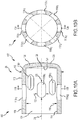
- FIGS 9-10B generally illustrate various views of cap 28 of the electrode support structure assembly 12 shown in Figure 2 .
- cap 28 is generally cylindrical in shape and has a proximal portion 100, a distal portion 102, and an interior 104 and is configured to be coupled with plug 26 (coupling discussed in more detail below). In other embodiments, however, cap 28 may take on other shapes, such as rectangular or octagonal. Cap 28 is also configured to constrain movement of support members 30a-d.
- cap 28 is generally disposed along longitudinal axis 24 and has a circumferential wall 106 extending in the axial direction along longitudinal axis 24 and an axial end wall 108 at distal portion 102 extending inwardly from circumferential wall 106 in the radial direction.
- circumferential wall 106 and axial end wall 108 define interior 104.
- Circumferential wall 106 may have an outer surface 110 with an outer diameter 112, an inner surface 114 with an inner diameter 116, and apertures 118a 1 -d 2 through which support members 30a-d may extend. Apertures 118a 1 -d 2 may be configured to permit the fluid to exit interior 104.
- circumferential wall 106 has four pairs of apertures 118a 1 -d 2 , each pair corresponding to an individual support member 30a-d (as can best be seen in Figure 27 ).
- the two apertures (e.g ., 118a 1 , 118a 2 ) in each pair are diametrically opposed of one another about longitudinal axis 24 in accordance with an embodiment.
- circumferential wall 106 may have less than or more than eight apertures in accordance with other embodiments.
- apertures 118a 1 -d 2 may have a length 120 and a width 122.
- apertures 118a 1 -d 2 are generally the same size and shape; however, in other embodiments, the apertures may have different sizes and shapes.
- each aperture 118a 1 -d 2 is generally rectangular in shape with rounded corners and has substantially the same size and shape at outer surface 112 and at inner surface 114. However, it should be understood that each aperture may have a different size and/or shape at inner surface 114 and outer surface 112.
- each pair of apertures 118a 1 -d 2 may be offset a distance from the proximally adjacent pair of apertures 118a-d in the axial direction.
- apertures 118a 1 , 118a 2 may be disposed most proximally in the axial direction, followed by apertures 118b 1 , 118b 2 , then apertures 118c 1 , 118c 2 , and lastly, apertures 118d 1 , 118d 2 .
- apertures 118a-d may be disposed in a number of ways relative to each other and that the sequential offset order may be varied.
- apertures 118a 1 -d 2 may not be offset from one another and, instead, lie in the same radial planes along longitudinal axis 24 (i.e., apertures 118a 1 -d 2 may be substantially aligned in the axial direction).
- Axial end wall 108 may have an inner surface 124 and an outer surface 126. Outer surface 126 of axial end wall 108 may extend from outer surface 110 of circumferential wall 106, and inner surface 124 of axial end wall 108 may extend from inner surface 114 of circumferential wall 106, in accordance with some embodiments.
- inner surface 124 of axial end wall 108 has an apex 128 located on longitudinal axis 24 and is generally conical in shape. It should be understood, however, that inner surface 124 can take on a number of profiles or shapes. For example and without limitation, inner surface 124 may be flat or rounded. Outer surface 126 of axial end wall 108 may be rounded in accordance with one embodiment.
- Figures 11-16 generally illustrate various views of support member 30a of electrode support structure assembly 12 shown in Figure 2 . Although only support member 30a is illustrated in Figures 11-16 , support members 30b-d are identical to support member 30a in the illustrated embodiment. Having support members 30a-d be identical makes fabrication of assembly 12 more cost-effective. However, it should be understood that support members 30a-d do not have to be identical in size and shape in accordance with other embodiments.
- FIG 11 is an isometric view of support member 30a illustrated in Figure 2 .
- Support members 30a-d are deflectable and configured to assume different configurations during operation.
- electrode support structure assembly 12 (once assembled) can comprise a "basket" in which each of the support members 30a-d can splay or bow radially outwardly (as best seen in Figure 2 ).
- the particular shape of the "basket” can vary.
- one or more of the support members 30a-d can splay or bow radially outwardly and uniformly (relative to each other) along the length of assembly 12, away from longitudinal axis 24, or one or more of the support members 30a-d can splay or bow radially outwardly in varying amounts along the length of assembly 12.
- the resulting "basket” is generally symmetric about the longitudinal axis 24 of assembly 12 in accordance with some embodiments.
- support members 30a-d can assume any number of other shapes in accordance with various embodiments.
- first and caps 26, 28 and support members 30a-d extend along longitudinal axis 24, they may have their own individual longitudinal axis, with each axis being parallel or at angle to one another.
- Support member 30a may have proximal portions 130a, 132a, intermediate portions 134a, 136a, and a distal portion 138a. Although in the illustrated embodiment support member 30a is one continuous generally circular piece, one of ordinary skill in the art will understand that support member 30a can be any number of distinct pieces. For example, and without limitation, support member 30a may be cut at distal portion 138a to form two generally semi-circular members. In one embodiment, proximal portions 130a, 132a are generally parallel to each other and longitudinal axis 24 of assembly 12.
- Figure 15 is a plan view of proximal portions 130a, 132a of support member 30a of Figure 11 prior to formation (as if support member 30a were laid out straight and unbent).
- Proximal portions 130a-d, 132a-d of each support member 30a-d are configured to be coupled together, as will be described in more detail herein below in connection with Figures 17-24 , and to distal portion 22 of catheter body 20 (shown in Figure 1 ).
- proximal portions 130a, 132a each include an indicator slot 140a, 142a and a constraining slot 144a, 146a.
- indicator slots 140a, 142a are generally diametrically opposed of one another, and constraining slots 144a, 146a are generally diametrically opposed of one another as well.
- indicator slots 140a, 142a serve as a visual aid in fabricating assembly 12.
- indicator slots 140a, 142a may indicate the location at which to cut support member 30a before, during, or after assembly.
- constraining slots 144a, 146a are configured to secure proximal portions 132a, 134a of support member 30a in the axial direction and may each have a width 148, 150, a length 152, 154, and inner edges 156a, 158a, 160a, 162a, each inner edge extending in the radial direction.
- inner edges 156a, 158a, 160a, 162a are illustrated as being generally perpendicular relative to longitudinal axis 24, one of ordinary skill in the art will understand that edges 156a, 158a, 160a, 162a may extend at various angles relative to longitudinal axis 24.
- Support member 30a further includes sides 164a, 166a (shown in Figure 16 ).
- indicator slot 140a and constraining slot 144a of proximal portion 130a are disposed on side 164a and may face a first radial direction
- indicator slot 142a and constraining slot 146a of proximal portion 132a are disposed on side 166a and may face a second radial direction that is generally 180 degrees from the first radial direction (about axis 24).
- each slot 140a, 142a, 144a, 146a has rounded corners. In other embodiments, the corners may not be rounded.
- support member 30a has a generally rectangular cross section with rounded corners.
- support member 30a generally has the same cross-sectional shape throughout its length.
- support member 30a may have varying cross sections in different places throughout its length.
- support member 30a has substantially the same width throughout its length.
- support member 30a may have varying widths (and other dimensions) throughout proximal portions 130a, 132a, intermediate portions 134, 136a, and/or distal portion 138a.
- intermediate portions 134a, 136a of support member 30a extend from proximal portions 130a, 132a, respectively, and connect to distal portion 138a.
- intermediate portions 134a, 136a are configured to support electrodes 40.
- Distal portion 138a is configured to couple to intermediate portions 134a, 136a and includes a nose 170a protruding in the axial direction and extending radially inwardly from intermediate portions 134a, 136a toward longitudinal axis 24 and having a radius of curvature 172 (as best seen in Figure 14 ).
- Nose 170a may also have radii of curvature 174, 176 where it connects to intermediate portions 134a, 136a. Although nose 170a is illustrated as being rounded, nose 170a may take on a variety of shapes and/or curvatures in accordance with other embodiments. Nose 170a may be configured and/or shaped to constrain movement thereof in interior 104 of cap 28 (as best illustrated in Figure 26 ). Moreover, nose 170a may correspond in shape to at least one of tapered portion 66 and distal tip 68 of plug 26 ( Figure 26 ).
- Figures 17-25 generally illustrate the coupling of arms 30' to proximal subassembly 32 and the components used therewith in accordance with one embodiment of the present teachings.
- Figure 17 is a partially exploded view of proximal subassembly 32 illustrated in Figure 3 .
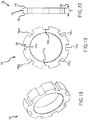
- Proximal subassembly 32 may include a constraining ring 182, a torsion ring 184, and a retainer ring 186.
- Figures 18-20 generally illustrate various views of constraining ring 182. In the illustrated embodiment, constraining ring 182 and torsion ring 184 have the same general shape except for the width of the grooves contained therein (to be described in more detail herein below).
- Constraining ring 182 is configured to couple with support members 30a-d (via constraining slots 144a-d, 146a-d in support members 30a-d, as shown in Figure 15 with respect to support member 30a) and constrain movement of proximal portions 130a-d, 132a-d of support members 30a-d (as seen in Figures 11-12 with respect to support member 30a) in the axial direction.
- support members 30a-d are flexible, other portions of support members 30a-d may move in the axial direction, namely intermediate portions 134, 136 and distal portion 138 (as shown in Figures 11-12 ).
- constraining ring 182 has an outer diameter 188 and includes a proximal face 190, a distal face 192, and eight grooves 194a 1 -d 2 , each groove 194a 1 -d 2 having a width 196 and a length 198.
- constraining ring 182 is configured to support one proximal portion 130a-d or 132a-d of one support member 30a-d.
- grooves 194a 1 , 194a 2 (being diametrically opposed of one another) are configured to support proximal portions 130a, 132a of support member 30a, respectively.
- grooves 194b 1 , 194b 2 may support proximal portions 130b, 132b of support member 30b, respectively; grooves 194c 1 , 194c 2 may support proximal portions 130c, 132c of support member 30c, respectively; and grooves 194d 1 , 194d 2 may support proximal portions 130d, 132d of support member 30d, respectively.
- Figure 17 for clarity only proximal portions 130a, 132a of support member 30a are labeled. If illustrated, the other support members 30b-d would include similar labels ending with the letters "b", "c", and "d", as appropriate.
- the number of grooves 194a 1 -d 2 in the constraining ring 182 may correspond to the number of proximal portions 130a-d, 132a-d of support members 30a-d. Because in the illustrated embodiment, there are four support members 30a-d, each with two proximal portions 130a-d, 132a-d, there are eight grooves 194a 1 -d 2 in constraining ring 182.
- the number of grooves in constraining ring may vary and may not necessarily correlate to the number of support members and/or proximal portions of support members.
- proximal portion 130a-d, 132a-d of support members 30a-d may be secured within constraining ring 182.
- support members 30a-d are identical parts; therefore, constraining slots 144a-d, 146a-d (constraining slots 144a, 146a shown in Figure 15 ) all lie in the same relative position along the length of support members 30a-d. It should be understood, however, that the position of constraining slots 144a-d, 146a-d may vary.
- constraining slots 144a, 146a on support member 30a may be offset from constraining slots 144d, 146d on support member 30d to compensate for the axial displacement of noses 170a-d (due to the stacking of noses 170a-d in the axial direction, as will be discussed in more detail below in connection with Figures 26-27 ).
- edges 156a, 158a of slots 144a, 146a of support member 30a contact proximal face 190 of constraining ring 182, and edges 160a, 162a of slots 144a, 146a of support member 30a contact distal face 192 of constraining ring 182.
- This configuration constrains movement of proximal portions 130a, 132a of support member 30a in the axial direction.
- Width 196 of grooves 194a 1 -d 2 and the width of the portion of support members 30a-d disposed within grooves 194a 1 -d 2 may be designed accordingly.
- width 196 of grooves 194a 1 -d 2 may be 0.0115 inches (0,029 cm), and the width of the portion of support members 30a-d disposed within grooves 194a 1 -d 2 may be 0.010 inches (0,025 cm).
- length 198 of grooves 194a 1 -d 2 and length 152, 154 of slots 144a-d, 146a-d of support members 30a-d may be designed accordingly.
- length 198 of grooves 194a 1 -d 2 may be 0.020 inches (0,051 cm), and length 152, 154 of slots 144a-d, 146a-d of each support member 30a-d may be 0.024 inches (0,061 cm).
- torsion ring 184 may be disposed distally of constraining ring 182 and may be configured to couple with proximal portions 130a-d, 132a-d of support members 30a-d and constrain rotation of proximal portions 130a-d, 132a-d of support members 30a-d about longitudinal axis 24.
- support members 30a-d are flexible, other portions of support members 30a-d may twist slightly in the rotational direction, namely intermediate portions 134a-d, 136a-d and distal portions 138a-d.
- torsion ring 184 has an outer diameter 200 and includes a proximal face 202, a distal face 204, and eight grooves 206a 1 -d 2 , each groove 206a 1 -d 2 having a width 208 and a length 210 and is configured to support one proximal portion 130a-d or 132a-d of support member 30a-d.
- grooves 206a 1 , 206a 2 are configured to support proximal portion 130a and proximal portion 132a of support member 30a, respectively.
- grooves 206b 1 , 206b 2 may support proximal portions 130b, 132b of support member 30b, respectively; grooves 206c 1 , 206c 2 may support proximal portions 130c, 132c of support member 30c, respectively; and grooves 206d 1 , 206d 2 may support proximal portions 130d, 132d of support member 30d, respectively.
- the number of grooves 206a 1 -d 2 in torsion ring 184 may correspond to the number of proximal portions 130a-d, 132a-d of support members 30a-d.
- each support member 30a-d there are four support members 30a-d each with two proximal portions 130a-d, 132a-d, there are eight grooves 206a 1 -d 2 in torsion ring 184.
- the number of grooves in the torsion ring may vary and may not necessarily correlate to the number of support members and/or proximal portions of support members.
- not every proximal portion 130a-d, 132a-d of support members 30a-d may be secured within torsion ring 184.
- proximal face 202 of torsion ring 184 abuts distal face 192 of constraining ring 182 in the axial direction (as best seen in Figure 17 ).
- torsion ring 184 may not abut constraining ring 182 and/or be disposed proximally of constraining ring 182.
- constraining ring 182 and torsion ring 184 may be constructed to be one piece rather than two separate rings.
- One of ordinary skill in the art would understand that not all rings 182, 184, 186 may be necessary.
- edges 164a-d, 166a-d of proximal portions 130a-d, 132a-d of support members 30a-d are disposed within grooves 206a 1 -d 2 to constrain rotation about longitudinal axis 24.
- Width 208 of grooves 206a 1 -d 2 and width of the portion of support members 30a-d disposed within grooves 206a 1 -d 2 may be designed accordingly.
- width 208 of grooves 206a 1 -d 2 may be 0.0155 inches (0,039 cm), and the width of the portion of support members 30a-d disposed within grooves 206a 1 -d 2 maybe 0.014 inches (0,036 cm).
- retainer ring 186 may be disposed around constraining ring 184 and torsion ring 182 and may be configured to secure proximal portions 130a-d, 132a-d of support members 30a-d relative to at least one of constraining ring 184 and torsion ring 182.
- retainer ring 186 may include an outer surface 212, an inner surface 214, and an inner diameter 215.
- retainer ring 186 may further include a proximal face 216, a distal face 218, a width 220, and apertures 222, 224.
- Inner surface 214 is configured to contact proximal portions 130a-d, 132a-d of support members 30a-d and/or constraining ring 182 and torsion ring 184.
- inner diameter 215 of retainer ring 186 may be 0.092 inches (0,23 cm)
- outer diameter 188 of constraining ring 182 and outer diameter 200 of torsion ring 184 may be 0.0875 inches (0,22 cm) in accordance with one embodiment (diameters 188, 200 shown in Figures 20 and 23 , respectively).
- Apertures 222, 224 may be configured to be filled with epoxy or adhesive to allow for greater bond strength.
- apertures 222, 224 there are eight apertures 222, 224: four apertures 222 are circular and are disposed centrally along width 220 in the axial direction, and four apertures 224 are semi-circular and are disposed along distal face 218.
- width 220 of retainer ring 186 may be 0.040 inches (0,10 cm)
- widths 196, 208 of constraining ring 182 and torsion ring 184 may be 0.020 inches (0,051 cm) each.
- support members 30a-d are coupled to/within rings 182, 184, 186 with non-conductive coating 38 abutting distal faces 204, 218 of torsion ring and retainer ring, respectively.
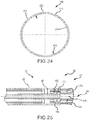
- Figure 25 is a cross-sectional view of the connection between elongated catheter body 20 and assembly 12' of Figure 3 .
- fluid delivery line 46 may extend along longitudinal axis 24.
- fluid delivery line 46 may include at least one port, such as port 225.
- Port 225 may allow fluid to exit fluid delivery line 46 and may be located near proximal subassembly 32 outside of catheter body 20.
- port 225 may be located at any point along longitudinal axis 24 outside catheter body 20.
- catheter system 10 in the illustrated embodiments allows for irrigation near proximal subassembly 32 via port 225 and distal subassembly 23 (as shown in Figure 2 ) via apertures 118a 1 -d 2
- catheter system 10 may only allow for irrigation at one subassembly 32, 23 and/or at a point(s) therebetween.
- fluid delivery line 46 may include three ports that are spaced 120 degrees apart about longitudinal axis 24 and are in the same longitudinal position along axis 24. In other embodiments, there may be any number of ports, and they may lie in various positions along and about longitudinal axis 24.
- the ports may be the same or different sizes and configurations other than circular (as illustrated).
- Figures 26-27 generally illustrate a portion of the electrode support structure assembly 12 of Figure 2 at distal subassembly 23.
- fluid delivery line 46 is connected to connector portion 48 of plug 26 such that fluid enters lumen 52 at proximal portion 42 of plug 26 and travels toward distal tip 68.
- cap 28 is laser-welded to plug 26 at ring portion 62 of plug 26.
- cap 28 can be laser-welded to plug 26 in four different areas along ring portion 62 where it contacts cap 28.
- cap 28 can be laser-welded to plug 26 along cylindrical portion 64 where it contacts cap 28.
- plug 26 and cap 28 can be coupled together using screws.
- Screws may extend through ring portion 62 into circumferential wall 110 of cap 28 and/or through circumferential wall 110 of cap 28 into cylindrical portion 64 of plug 26.
- plug 26 and cap 28 may be coupled using a variety of different mechanisms known in the art. Referring to Figure 27 , in the illustrated embodiment, apertures 118a 1 , 118a 2 and 118b 1 , 118b 2 of cap 28 are aligned with channels 90, 92 of plug 26. However, cap 28 may be oriented in a number of ways relative to plug 26. While plug 26 may be axially aligned with cap 28, it is not necessary for them to be rotationally aligned. Such rotational alignment may make fabrication more costly.
- apertures 118a 1 , 118a 2 are oriented around tapered portion 66 of plug 26 such that tapered portion 66 is aligned with apertures 118a 1 , 118a 2 in the radial direction.
- distal tip 68 of plug 26 is generally adjacent to portions of apertures 118b 1 -d 2 and is not adjacent to apertures 118a 1 , 118a 2 in the radial direction.
- portions of apertures 118b 1 -d 2 are disposed over distal tip 68 of plug 26 in the radial direction.
- each support member 30a-d extends through a pair of diametrically opposed apertures 118a 1 -d 2 , and noses 170a-d of support members 30a-d are disposed in interior 104 of cap 28 distally of distal tip 68 of plug 26 in accordance with some embodiments.
- Such configuration may constrain movement of noses 170a-d within interior 104 of cap 28.
- radius of curvature 172 (as shown in Figure 14 ) of nose 170a of arm 30a (being immediately adjacent to plug 26 in the axial direction) corresponds to tapered portion 66 and radius of curvature 94 of distal tip 68.
- plug 26 may further be configured to constrain movement of noses 170a-d. At some times during collapse or expansion, nose 170a may rest on tapered portion 66 and/or distal tip 68. At other times, nose 170a may float in apertures 118a 1 , 118a 2 and not physically contact plug 26. With particular reference to Figure 26 , noses 170a-d of support members 30a-d may overlap along longitudinal axis 24.
- support member 30a is generally oriented in the vertical position and is disposed in the most proximal position; support member 30b is disposed distally of arm 30a and is generally oriented in the horizontal position; support member 30c is disposed distally of support member 30b and is generally oriented 45 degrees clockwise about longitudinal axis 24 from support member 30b (when viewing assembly 12 as illustrated in Figure 27 ); and support member 30d is disposed in the most distal position and is generally oriented 45 degrees clockwise about longitudinal axis 24 from support member 30a (when viewing assembly 12 as illustrated in Figure 27 ).
- support members 30a-d may be overlapped in a variety of different ways and extend through various apertures 118a 1 -d 2 in accordance with other embodiments. Noses 170a-d of support members 30a-d may contact each other at various times during collapse and/or expansion.
- Length 120 and width 122 (as shown in Figure 10A ) of apertures 118a 1 -d 2 may be designed to accommodate the movement of support members 30a-d (and their noses 170a-d) during expansion and collapse.
- apertures 118a 1 -d 2 should not be too large to allow noses 170a-d of support members 30a-d to exit interior 104 of cap 28 through apertures 118a 1 -d 2 .
- apertures 118a 1 -d 2 should also not be too small to prevent support members 30a-d from moving freely during expansion and collapse.
- length 120 of apertures 118a 1 -d 2 is 0.030 inches (0,076 cm); width 122 of apertures 118a 1 -d 2 is 0.0155 inches (0,039 cm); a width 228 of support members 30a-d is 0.014 inches (0,036 cm); and radii of curvature 174 and 176, 172 of noses 170a-d are 0.025 inches (0,064 cm) and 0.020 inches (0,051 cm), respectively (each measured to the part centerline of support member 30a-d; refer to Figures 10A , 14 , and 27 for illustration of dimensions).
- apertures 118a 1 -d 2 may affect the flow other fluids within the body, such as blood.
- the larger the aperture the less positive pressure across circumferential wall 1 10 of cap 28, such that blood may flow inside interior 104 of cap 28.
- the smaller the aperture however, the more likely it is that blood will be kept out of interior 104.
- support member 30a which (in the illustrated embodiment) is disposed immediately adjacent of distal tip 68, and travels through channels 90, 92 of distal tip 68.
- Tapered portion 66, distal tip 68, channels 90, 92, and noses 170a-d of support members 30a-d are designed to allow fluid to exit lumen 52 of plug 26 freely and to not block or inoperatively constrain the exit of fluid from lumen 52.
- width 228 of support member 30a (and thus of nose 170a) was equal to width 97, 99 of channels 90, 92, fluid may be inoperatively constrained in lumen 52 (widths 97, 99 shown in Figure 8 ).
- width 97, 99 of channels 90, 92 may be less than width 228 of support members 30a-d. In accordance with other embodiments, width 97, 99 of channels 90, 92 may be greater than width 228 of support members 30a-d. Fluid may eventually exit interior 104 of cap 28 through apertures 118a 1 -d 2.
- joinder references do not necessarily infer that two elements are directly connected and in fixed relation to each other.
- the terms "electrically connected” and “in communication” are meant to be construed broadly to encompass both wired and wireless connections and communications. It is intended that all matter contained in the above description or shown in the accompanying drawings shall be interpreted as illustrative only and not limiting. Changes in detail or structure may be made without departing from the disclosure as defined in the appended claims.
Description
- This disclosure relates generally to an electrode support structure assembly. In particular, the instant disclosure relates to an electrode support structure assembly for basket catheters including a plurality of arms.
- This background description is set forth below for the purpose of providing context only. Therefore, any aspects of this background description, to the extent that it does not otherwise qualify as prior art, is neither expressly nor impliedly admitted as prior art against the instant disclosure.
- Electrophysiology catheters are used in a variety of diagnostic, therapeutic, and/or mapping and ablative procedures to diagnose and/or correct conditions such as atrial arrhythmias, including for example, ectopic atrial tachycardia, atrial fibrillation, and atrial flutter. Arrhythmias can create a variety of conditions including irregular heart rates, loss of synchronous atrioventricular contractions, and stasis of blood flow in a chamber of a heart which can lead to a variety of symptomatic and asymptomatic ailments and even death.
- Typically, a catheter is deployed and manipulated through a patient's vasculature to the intended site, for example, a site within a patient's heart or a chamber or vein thereof. The catheter carries one or more electrodes that can be used for cardiac mapping or diagnosis, ablation and/or other therapy delivery modes, or both, for example. Once at the intended site, treatment can include, for example, radio frequency (RF) ablation, cryoablation, laser ablation, chemical ablation, high-intensity focused ultrasound-based ablation, microwave ablation, and/or other ablation treatments. The catheter imparts ablative energy to cardiac tissue to create one or more lesions in the cardiac tissue and oftentimes a contiguous or linear and transmural lesion. This lesion disrupts undesirable cardiac activation pathways and thereby limits, corrals, or prevents errant conduction signals that can form the basis for arrhythmias.
- Various catheters and electrode arrangements can be employed for different purposes. Catheters having basket-shaped electrode support structures are generally described in, for example and without limitation,
U.S. Patent No. 5,772,590 . Generally, catheters having basket-shaped electrode support structures are introduced through a guiding sheath with the electrode support structure in a folded or collapsed position within the sheath so that the electrode support structure does not damage tissue during its introduction. Once the catheter reaches its intended position within the heart, the guiding sheath can be removed and/or the catheter extended therefrom and the electrode support structure can be allowed to radially outwardly expand for cardiac mapping or diagnosis, ablation, and/or other therapy delivery modes, or both, for example. - Typically, basket-shaped electrode support structures comprise a plurality of arms that can be formed from laser-cut tubing and be integral at one end or that comprise discrete, separate elements. The distal ends of each of these plurality of arms generally must be joined together. For example, the distal ends of each of the plurality of arms can be mounted around a first piece of tubing and then be held in place by a second piece of tubing as generally described and illustrated in
U.S. Patent No. 7,522,950 . - It may be desirable for each of the arms to be joined in such a way that the arms are configured to straighten evenly when the electrode support structure is collapsed. However, it may be difficult for the electrode support structure to collapse evenly if manufacturing variances have resulted in differences in the individual lengths of the arms. It may also be difficult for the electrode support structure to collapse evenly if one or more of the arms have experienced a change in length relative to the remainder of the arms, such as during manipulation of the electrode support structure around a curve, for example. If the arms do not straighten evenly when the electrode support structure is collapsed, a protrusion or "loop" can form at the distal end of one or more of the plurality of arms. Continued collapse or multiple collapses of the electrode support structure can potentially cause fatigue at the point of the protrusion or "loop" and ultimately fracture the arm. Moreover, when the distal ends of the arms are fixed in place (e.g., mounted between two pieces of tubing), the distal flexibility of the arms may be limited, thereby adversely impacting the collapsibility of the electrode support structure. In addition, stress imparted at the distal end of the electrode support structure during collapse and/or expansion of the electrode support structure can also result in the failure of any arm or other element that may be configured to join the distal ends of the arms together.
- Additionally, when the electrode support structure is in an expanded state, electrode distribution may not be uniform in accordance with some electrode arrangements. Moreover, during expansion and/or collapse of the electrode support structure (e.g., when the electrode support structure is emerging from or being retracted into a delivery sheath), some electrode arrangements may possibly result in electrode-to-electrode physical contact and/or electrical short circuits, which may cause electrode wear and/or limit electrode functionality. In addition, some electrode arrangements may not minimize the profile of the electrode support structure during collapse of the electrode support structure, which can result in electrode damage when the electrode support structure is being delivered through the delivery sheath, especially when being delivered through a tortuously angulated pathway.
- Basket-shaped electrode support structures can include an expander having a distal end attached to a distal end of the electrode support structure. The expander includes a proximal end that extends out of a proximal end of a catheter or other medical device employing the electrode support structure to a control handle. The expander can be moved longitudinally relative to the catheter or other medical device to expand and contract the electrode support structure. The expander is generally coaxial with the catheter. An expander will not generally allow for free axial movement of the electrode support structure if the electrode support structure is being diametrically constrained in some way.
- Several difficulties may be encountered, however, during these medical procedures using some existing basket catheters. For example, a slowing or stoppage of the flow of blood may occur between the arms of the basket catheter, e.g., where the arms are attached to the catheter. Irrigation is desirable to keep fluid moving between the arms of the catheter.
- There is therefore a need to minimize and/or eliminate one or more of the problems as set forth above. The foregoing discussion is intended only to illustrate the present field and should not be taken as a disavowal of claim scope. Further electrode support structures are known from
US 2013/0172715 A1 andUS 5,471,982 A . - Among other things, various embodiments disclosed herein are directed to an electrode support structure assembly.
- An electrode support structure assembly in a body in accordance with one embodiment of the present teachings includes a plug, a cap, and a plurality of support members. The plug defines a longitudinal axis and is configured to connect to a fluid delivery line. The plug also includes a lumen configured to receive a fluid from the fluid delivery line, the lumen extending in an axial direction and comprising an axial distal end. The plug further includes a distal tip adjacent to the axial distal end of the lumen and comprising a first channel extending across the distal tip. The cap is disposed around at least a portion of the plug and includes a first wall extending in the axial direction and a plurality of apertures. The cap further includes a second wall extending inwardly from the first wall in a radial direction. The first wall and the second wall of the cap define an interior. Each support member of the plurality of support members comprises a distal portion. The distal tip of the plug and the distal portions of the plurality of support members are at least partially disposed in the interior of the cap. The cap is configured to constrain relative movement of the distal portions of the plurality of support members with respect to the cap, and the first channel of the plug and at least one of the plurality of support members are configured to direct a fluid outwardly in a radial direction after exiting the lumen of the plug.
- An electrode support structure assembly with a longitudinal axis, a proximal portion, and a distal portion in accordance with another embodiment of the present teachings includes a support member, a constraining ring, a torsion ring, and a retainer ring. The support member includes a first proximal portion extending in the axial direction and a second proximal portion generally parallel to the first proximal portion. The constraining ring is disposed at the proximal portion of the assembly and is configured to constrain the first and second proximal portions of the support member in the axial direction. The torsion ring is disposed at the proximal portion of the assembly and is configured to constrain rotation of the first and second proximal portions of support member about the longitudinal axis. The retainer ring partially surrounds at least one of the constraining ring and torsion ring and is configured to secure the first and second proximal portions of the support member relative to at least one of the constraining ring and torsion ring.
- It is desirable to provide an electrode support structure assembly that can include an element joining the distal end of each of the plurality of arms that is configured to provide freedom for each of the plurality of arms to move independently along an axis of the electrode support structure. This may help ensure that the arms are configured to straighten evenly when the electrode support structure is collapsed, It is also desirable to provide an electrode support structure assembly that can include an element joining the distal end of each of the plurality of arms that is configured to provide freedom for each of the plurality of arms to articulate relative to an axis of the electrode support structure such that each of the plurality of arms can be positioned at numerous angles relative to the axis of the electrode support structure in order to minimize stress imparted at the distal end of the electrode support structure during collapse and/or expansion. It is also desirable to provide an electrode support structure that can be configured to allow for free, uniform axial displacement even if the electrode support structure is being diametrically constrained in some way. It is also desirable to effectively deliver irrigation fluid to the distal end of the catheter while concurrently keeping the components of the catheter as small and compact as possible.
- The foregoing and other aspects, features, details, utilities, and advantages of the present disclosure will be apparent from reading the following description and claims, and from reviewing the accompanying drawings.
-
-
Figure 1 is a diagrammatic view of a catheter system that is designed to perform one or more diagnostic and/or therapeutic functions in accordance with at least one embodiment of the present teachings. -
Figure 2 is an isometric view of an electrode support structure assembly in accordance with one embodiment of the present teachings. -
Figure 3 is a lateral elevational view of an electrode assembly in accordance with another embodiment of the present teachings. -
Figure 4 is an isometric view of a portion of the electrode assembly illustrated inFigure 3 . -
Figures 5A-5B are isometric views of a plug of the electrode support structure assembly illustrated inFigure 2 . -
Figure 6 is a rear elevational view of the plug illustrated inFigures 5A-5B , -
Figure 7 is a cross-sectional view of the plug ofFigure 6 taken along line 7-7. -
Figure 8 is a front elevational view of the plug illustrated inFigures 5A-5B . -
Figure 9 is an isometric view of a cap of the electrode support structure assembly illustrated inFigure 2 . -
Figure 10A is a cross-sectional view of the cap ofFigure 9 taken alongline 10A-10A inFigure 10B . -
Figure 10B is a cross-sectional view of the cap ofFigure 9 taken alongline 10B-10B inFigure 10A . -
Figure 11 is an isometric view of a support member of the electrode support structure assembly illustrated inFigure 2 . -
Figure 12 is a lateral elevational view of the support member ofFigure 11 . -
Figure 13 is a top elevational view of the support member ofFigure 11 , -
Figure 14 is a lateral view of a nose of the support member illustrated inFigure 11 . -
Figure 15 is a plan view of proximal portions of the support member ofFigure 11 prior to formation. -
Figure 16 is a cross-sectional view of the proximal portion of the support member ofFigure 15 taken along line 16-16. -
Figure 17 is a partially exploded view of a proximal subassembly of the electrode assembly illustrated inFigure 3 . -
Figure 18 is an isometric view of a constraining ring of the proximal subassembly illustrated inFigure 17 . -
Figure 19 is a front elevational view of the constraining ring ofFigure 18 . -
Figure 20 is a lateral elevational view of the constraining ring ofFigure 18 . -
Figure 21 is an isometric view of a torsion ring of the proximal subassembly illustrated inFigure 17 . -
Figure 22 is a front elevational view of the torsion ring ofFigure 21 . -
Figure 23 is a lateral elevational view of the torsion ring ofFigure 21 . -
Figure 24 is a front elevational view of a retainer ring of the proximal subassembly ofFigure 17 . -
Figure 25 is a cross-sectional view of the connection between an elongated catheter body and the electrode assembly ofFigure 3 . -
Figure 26 is a cross-sectional view of a portion of the electrode support structure assembly ofFigure 2 taken along line 26-26 inFigure 27 . -
Figure 27 is a cross-sectional view of the portion of the electrode support structure assembly ofFigure 26 taken along line 27-27. - It may be desirable to be able to deliver saline or an anticoagulant such as a heparinized saline solution or other fluid in a basket catheter during various medical procedures, e.g., to reduce the risk of blood clot or thrombus formation. One effective way to prevent blood coagulation and thrombus formation is to irrigate the electrode with heparinized saline. It is still further desirable to be able to do all of this while retaining the ability to axially move a deployment mechanism, e.g., a basket catheter, or electrode support structure itself. Moreover, designing components of the electrode support structure assembly to fit tightly together (so as to keep the catheter footprint as small as possible) can interfere with the desire to provide unconstrained delivery of irrigation fluid.
- Various embodiments are described herein to various apparatuses, systems, and/or methods. Numerous specific details are set forth to provide a thorough understanding of the overall structure, function, manufacture, and use of the embodiments as described in the specification and illustrated in the accompanying drawings. It will be understood by those skilled in the art, however, that the embodiments may be practiced without such specific details. In other instances, well-known operations, components, and elements have not been described in detail so as not to obscure the embodiments described in the specification. Those of ordinary skill in the art will understand that the embodiments described and illustrated herein are non-limiting examples, and thus it can be appreciated that the specific structural and functional details disclosed herein may be representative and do not necessarily limit the scope of the embodiments, the scope of which is defined solely by the appended claims.
- Reference throughout the specification to "various embodiments," "some embodiments," "one embodiment," or "an embodiment," or the like, means that a particular feature, structure, or characteristic described in connection with the embodiment is included in at least one embodiment. Thus, appearances of the phrases "in various embodiments," "in some embodiments," "in one embodiment," or "in an embodiment," or the like, in places throughout the specification are not necessarily all referring to the same embodiment. Furthermore, the particular features, structures, or characteristics may be combined in any suitable manner in one or more embodiments. Thus, the particular features, structures, or characteristics illustrated or described in connection with one embodiment may be combined, in whole or in part, with the features, structures, or characteristics of one or more other embodiments without limitation given that such combination is not illogical or non-functional.
- It will be appreciated that the terms "proximal" and "distal" may be used throughout the specification with reference to a clinician manipulating one end of a medical device or instrument used to treat a patient. The term "proximal" refers to the portion of the device closest to the clinician (or to a robotic control configured to manipulate the device) and the term "distal" refers to the portion located furthest from the clinician. It will be further appreciated that for conciseness and clarity, spatial terms such as "vertical," "horizontal," "up," and "down" may be used herein with respect to the illustrated embodiments. However, medical devices may be used in many orientations and positions, and these terms are not intended to be limiting or absolute. Moreover, as used herein, the term "basket" is not limited to the illustrated configuration, but can include other designs such as spherical or egg-shaped designs, for example.
- Referring now to the drawings wherein like reference numerals are used to identify identical or similar components in the various views,
Figure 1 is a diagrammatic view of a catheter system 10 employing an electrode assembly 12' in accordance with an embodiment of the present teachings. Catheter system 10 includes ahandle 14 andconnectors 16 disposed proximal to handle 14 for making electrical connections to a visualization, navigation, and/or mapping system (not shown) such as those systems available under the brand name Ensite™ NavX™ (aka Ensite™ "Classic" as well as newer versions of the Ensite™ system, denoted as Ensite™ Velocity™) and available from St. Jude Medical, Inc.Handle 14 can have a uni-directional design, a bi-directional design, or any other suitable design and be accordingly configured to steer electrode assembly 12', as discussed in more detail in commonly assignedU.S. Patent No. 8,676,290 . Catheter system 10 can also include anintroducer 18 located distally ofhandle 14 that may be used to deliver anelongated catheter body 20 into the body of a patient, through a hemostasis valve of another longer introducer, for example.Elongated catheter body 20 can extend fromintroducer 18.Elongated catheter body 20 can comprise an elongated tubular construction having one or more lumens.Elongated catheter body 20 can be flexible or bendable.Elongated catheter body 20 can be of any suitable construction and made of any suitable material as known to those of ordinary skill in the art.Elongated catheter body 20 can have any outer diameter, but may generally be configured for insertion into the vascalature of a body of a patient and, in some embodiments, be less than about 8 French.Elongated catheter body 20 can have an outer wall of any thickness, but may generally be configured so that one or more lumens can be disposed withinelongated catheter body 20 to accommodate pull wires, lead wires, sensor cables, and any other wires, cable, and/or tubes that may be needed in particular applications.Handle 14,connectors 16,introducer 18, andelongated catheter body 20 can be readily modified as dictated by the aesthetic or functional needs of particular applications. - Electrode assembly 12' is configured to extend from a
distal portion 22 ofelongated catheter body 20. Although electrode assembly 12' is described and illustrated in connection with an intracardiac catheter system 10, electrode assembly 12' may be utilized in connection with other types of medical devices, such as for example and without limitation, stone retrieval baskets, distal protection devices, renal artery ablation devices, snares, and other retrieval devices. As discussed in further detail below in connection withFigures 3-4 , assembly 12' may be configured to support electrodes and to be radially outwardly expandable and inwardly collapsible. -
Figure 2 is an isometric view of an electrodesupport structure assembly 12.Assembly 12 is configured to be mounted todistal portion 22 ofelongated catheter body 20.Assembly 12 is configured to be radially outwardly expandable relative toaxis 24 to an expanded arrangement as shown inFigure 2 .Assembly 12 defines alongitudinal axis 24 and may be configured to be radially inwardly collapsible relative toaxis 24 to a collapsed arrangement.Assembly 12 may comprise adistal subassembly 23 which may include aplug 26 and acap 28 disposed around a portion ofplug 26. Assembly may further includesupport members 30a-d.Support members 30a-d ofassembly 12 can be collapsed by an application of force, for example, by movingsupport members 30a-d into a sheath or introducer. Upon removal of the application force, for example, by movingsupport members 30a-d out of a sheath or introducer,support members 30a-d may return to the expanded arrangement. This expansion and collapse ofassembly 12 may alternatively or additionally be achieved by using a shape memory material forsupport members 30a-d in accordance with some embodiments. The expansion and collapse ofassembly 12 may be achieved by using a biasing mechanism in accordance with other embodiments. In the illustrated embodiment,assembly 12 may include foursupport members 30a-d. Although foursupport members 30a-d are mentioned in detail, there may be fewer or more support members in accordance with various embodiments. Each of thesupport members 30a-d may generally be evenly spaced circumferentially aroundaxis 24 of theassembly 12.Assembly 12 may further include a proximal subassembly 32 (best shown inFigure 17 ) to be described in more detail hereinbelow. Moreover,support members 30a-d may be generally circular in shape and may each have two free ends connected toproximal subassembly 32 withdistal subassembly 23 being disposed at the opposite end (seeFigure 11 ). - Still referring to
Figure 2 , catheter system 10 may further include afluid delivery line 46 in accordance with some embodiments.Fluid delivery line 46 may be connected to an irrigation system and include, for example and without limitation, an irrigation pump configured to supply irrigation fluid toassembly 12 and/ordistal portion 22 of catheter body 20 (shown inFigure 1 ). In an embodiment, whenassembly 12 is expanded (as illustrated inFigure 2 ),fluid delivery line 46 may be generally arc-shaped between proximal subassembly 32 (Figure 3 ) anddistal subassembly 23. When collapsed,fluid delivery line 46 is generally straight and lies alonglongitudinal axis 24. Such a configuration allowsfluid delivery line 46 to be free of any undue tension whileassembly 12 is being collapsed (e.g., into a guiding sheath). In one embodiment, the arc length offluid delivery line 46 is approximately the same (or slightly less than) the arc length ofsupport members 30a-d between proximal subassembly 32 (Figure 3 ) anddistal subassembly 23. One of ordinary skill in the art will understand thatfluid delivery line 46 may take on a number of other configurations. For example and without limitation,fluid delivery 46 may be generally straight when collapsed and expanded by being corrugated, functioning similarly as a spring. -
Figures 3-4 generally illustrate electrode assembly 12' (shown generally inFigure 1 ). Assembly 12' is similar toassembly 12 ofFigure 2 except that assembly 12' includes additional components.Fluid delivery line 46 has been omitted inFigure 4 for clarity. In the illustrated embodiment shown inFigures 3-4 , assembly 12' comprises arms 30', with each arm 30' comprising asupport member 30a-d, a non-conductive covering 38 surrounding eachsupport member 30a-d, andelectrodes 40. In accordance with some embodiments,support members 30a-d may each be a flexible wire and may be flat and/or composed of Nitinol or other like materials. Thenon-conductive covering 38 can comprise a biocompatible plastic tubing, such as polyurethane or polyimide tubing in accordance with some embodiments. Although these materials are mentioned in detail,support members 30a-d and covering 38 can be made of any other suitable materials known to those of ordinary skill in the art. For example and without limitation, the arms 30' can be designed withoutsupport members 30a-d if a sufficiently rigid non-conductive material is used. One or more of the arms 30' can have one ormore electrodes 40 mounted on the non-conductive covering 38 in accordance with various embodiments. The number and spacing ofelectrodes 40 on the arms 30' can vary in accordance with various embodiments. The material and configuration of arms 30' (and/orsupport members 30a-d) can vary, as generally shown and discussed inU.S. Patent No. 8,588,885 . Individual components of electrode support structure assembly 12 (Figure 2 ) will now be discussed in detail. A discussion of how the components interact and couple together will follow. -
Figures 5A-8 illustrate various views ofplug 26 of electrodesupport structure assembly 12 shown inFigure 2 . Referring toFigures 5A-5B , plug 26 has aproximal portion 42 and adistal portion 44. At itsproximal portion 42, plug 26 comprises aconnector portion 48 configured to connect to fluid delivery line 46 (connection best seen inFigure 26 ). In one embodiment,connector portion 48 may be generally cylindrical aboutlongitudinal axis 24 and include abarb 56 and aproximal end 58.Barb 56 is configured to securefluid delivery line 46 in place. In an embodiment, an adhesive may also be used to securefluid delivery line 46 in place. At its distal portion 44 (and as explained in more detail below), plug 26 is configured to control the directional flow of the fluid when assembled with other components described herein. In the illustrated embodiment, plug 26 further includes alumen 52 generally disposed alonglongitudinal axis 24 extending betweenproximal portion 42 and distal portion 44 (lumen 52 andlongitudinal axis 24 best seen inFigure 7 ). - In one embodiment, plug 26 is configured to couple with
cap 28 of assembly 12 (coupling ofelements Figure 26 ). Referring toFigure 5A , in one embodiment, plug 26 includes aring portion 62, acylindrical portion 64 distal ofring portion 62, a taperedportion 66 distal ofcylindrical portion 64, and adistal tip 68. Referring toFigure 7 , in the illustrated embodiment,ring portion 62 has aproximal face 70, adistal face 72, and an outer diameter 74 (as best seen inFigure 8 ) and abutsconnector portion 48 at itsproximal face 70.Cylindrical portion 64 may have an outer diameter 76 (as best seen inFigure 8 ), which (in one embodiment) is smaller than outer diameter 74 ofring portion 62.Tapered portion 64 may extend distally fromcylindrical portion 64 todistal tip 68 and may have adistal end 78. Moreover, taperedportion 64 may be tapered in the axial direction toward an axialdistal end 80 oflumen 52. In the illustrated embodiment,distal tip 68 is adjacent to axialdistal end 80 oflumen 52 and includeschannels 90, 92 (as best seen inFigure 8 ) and is rounded with a radius of curvature 94 (as best seen inFigure 7 ). -
Channels Figure 8 ),channels distal tip 68 andlongitudinal axis 24 withchannel 90 being oriented vertically andchannel 92 being oriented horizontally. As such,channels Channels length 96, 98 and awidth 97, 99 in accordance with some embodiments. As illustrated,channels channels channel length 96, 98. Additionally, in accordance with other embodiments,distal tip 68 may have one or more than two channels, with the channel(s) extending in various radial directions. For example and without limitation,distal tip 68 may have four channels, each equidistant from the adjacent channels aboutlongitudinal axis 24. It should be understood thatchannels longitudinal axis 24. In the illustrated embodiment,channels distal end 80 of lumen 52 (Figure 7 );channel 90 is perpendicular tolongitudinal axis 24 andchannel 92; andchannel 92 is perpendicular tolongitudinal axis 24 andchannel 90. In accordance with other embodiments, however,channels longitudinal axis 24 and/or from each other. - Referring particularly to
Figure 7 ,lumen 52 is generally configured to direct the fluid fromproximal portion 42 ofplug 26 todistal portion 44 ofplug 26. In an embodiment,lumen 52 lies alonglongitudinal axis 24 and extends fromproximal end 58 ofconnector portion 48 todistal end 78 of taperedportion 66. In the illustrated embodiment, axialdistal end 80 oflumen 52 corresponds withdistal end 78 of taperedportion 66. Althoughlumen 52 is illustrated as having a round cross section (best shown inFigures 6 and 8 ), one of ordinary skill in the art will appreciate thatlumen 52 can have a number of different cross sections. Moreover, plug 26 may include more than one lumen extending parallel or at an angle to longitudinal axis 24 (or another lumen) in accordance with other embodiments. -
Figures 9-10B generally illustrate various views ofcap 28 of the electrodesupport structure assembly 12 shown inFigure 2 . Referring toFigure 9 ,cap 28 is generally cylindrical in shape and has aproximal portion 100, adistal portion 102, and an interior 104 and is configured to be coupled with plug 26 (coupling discussed in more detail below). In other embodiments, however, cap 28 may take on other shapes, such as rectangular or octagonal.Cap 28 is also configured to constrain movement ofsupport members 30a-d. - Referring to
Figure 10A , in the illustrated embodiment,cap 28 is generally disposed alonglongitudinal axis 24 and has acircumferential wall 106 extending in the axial direction alonglongitudinal axis 24 and anaxial end wall 108 atdistal portion 102 extending inwardly fromcircumferential wall 106 in the radial direction. In an embodiment,circumferential wall 106 andaxial end wall 108 define interior 104.Circumferential wall 106 may have anouter surface 110 with anouter diameter 112, aninner surface 114 with aninner diameter 116, and apertures 118a1-d2 through whichsupport members 30a-d may extend. Apertures 118a1-d2 may be configured to permit the fluid to exit interior 104. Referring toFigure 10B , in the illustrated embodiment,circumferential wall 106 has four pairs of apertures 118a1-d2, each pair corresponding to anindividual support member 30a-d (as can best be seen inFigure 27 ). The two apertures (e.g., 118a1, 118a2) in each pair are diametrically opposed of one another aboutlongitudinal axis 24 in accordance with an embodiment. One of ordinary skill in the art will understand thatcircumferential wall 106 may have less than or more than eight apertures in accordance with other embodiments. Referring toFigure 10A , apertures 118a1-d2 may have alength 120 and awidth 122. In the illustrated embodiment, apertures 118a1-d2 are generally the same size and shape; however, in other embodiments, the apertures may have different sizes and shapes. In the illustrated embodiment, each aperture 118a1-d2 is generally rectangular in shape with rounded corners and has substantially the same size and shape atouter surface 112 and atinner surface 114. However, it should be understood that each aperture may have a different size and/or shape atinner surface 114 andouter surface 112. In an embodiment, each pair of apertures 118a1-d2 may be offset a distance from the proximally adjacent pair of apertures 118a-d in the axial direction. For example and without limitation, as best seen inFigure 10A , apertures 118a1, 118a2 may be disposed most proximally in the axial direction, followed by apertures 118b1, 118b2, then apertures 118c1, 118c2, and lastly, apertures 118d1, 118d2. One of ordinary skill in the art will appreciate that apertures 118a-d may be disposed in a number of ways relative to each other and that the sequential offset order may be varied. Moreover, apertures 118a1-d2 may not be offset from one another and, instead, lie in the same radial planes along longitudinal axis 24 (i.e., apertures 118a1-d2 may be substantially aligned in the axial direction).Axial end wall 108 may have aninner surface 124 and anouter surface 126.Outer surface 126 ofaxial end wall 108 may extend fromouter surface 110 ofcircumferential wall 106, andinner surface 124 ofaxial end wall 108 may extend frominner surface 114 ofcircumferential wall 106, in accordance with some embodiments. In an embodiment,inner surface 124 ofaxial end wall 108 has an apex 128 located onlongitudinal axis 24 and is generally conical in shape. It should be understood, however, thatinner surface 124 can take on a number of profiles or shapes. For example and without limitation,inner surface 124 may be flat or rounded.Outer surface 126 ofaxial end wall 108 may be rounded in accordance with one embodiment. -
Figures 11-16 generally illustrate various views ofsupport member 30a of electrodesupport structure assembly 12 shown inFigure 2 . Althoughonly support member 30a is illustrated inFigures 11-16 ,support members 30b-d are identical to supportmember 30a in the illustrated embodiment. Havingsupport members 30a-d be identical makes fabrication ofassembly 12 more cost-effective. However, it should be understood thatsupport members 30a-d do not have to be identical in size and shape in accordance with other embodiments. -
Figure 11 is an isometric view ofsupport member 30a illustrated inFigure 2 .Support members 30a-d are deflectable and configured to assume different configurations during operation. For example and without limitation, electrode support structure assembly 12 (once assembled) can comprise a "basket" in which each of thesupport members 30a-d can splay or bow radially outwardly (as best seen inFigure 2 ). The particular shape of the "basket" can vary. For example and without limitation, one or more of thesupport members 30a-d can splay or bow radially outwardly and uniformly (relative to each other) along the length ofassembly 12, away fromlongitudinal axis 24, or one or more of thesupport members 30a-d can splay or bow radially outwardly in varying amounts along the length ofassembly 12. The resulting "basket" is generally symmetric about thelongitudinal axis 24 ofassembly 12 in accordance with some embodiments. Although a "basket" shape is mentioned in detail,support members 30a-d can assume any number of other shapes in accordance with various embodiments. Although first and caps 26, 28 andsupport members 30a-d extend alonglongitudinal axis 24, they may have their own individual longitudinal axis, with each axis being parallel or at angle to one another. -
Support member 30a may haveproximal portions intermediate portions distal portion 138a. Although in the illustratedembodiment support member 30a is one continuous generally circular piece, one of ordinary skill in the art will understand thatsupport member 30a can be any number of distinct pieces. For example, and without limitation,support member 30a may be cut atdistal portion 138a to form two generally semi-circular members. In one embodiment,proximal portions longitudinal axis 24 ofassembly 12. -
Figure 15 is a plan view ofproximal portions support member 30a ofFigure 11 prior to formation (as ifsupport member 30a were laid out straight and unbent).Proximal portions 130a-d, 132a-d of eachsupport member 30a-d (proximal portions support member 30a shown inFigure 15 ) are configured to be coupled together, as will be described in more detail herein below in connection withFigures 17-24 , and todistal portion 22 of catheter body 20 (shown inFigure 1 ). Still referring toFigure 15 ,proximal portions indicator slot slot support member 30a into a generally circular shape (as shown inFigure 11 ),indicator slots slots indicator slots assembly 12. For example and without limitation,indicator slots support member 30a before, during, or after assembly. As will be described in more detail herein below in connection withFigures 18-20 , constrainingslots proximal portions support member 30a in the axial direction and may each have awidth length inner edges inner edges longitudinal axis 24, one of ordinary skill in the art will understand thatedges longitudinal axis 24.Support member 30a further includessides Figure 16 ). In one embodiment,indicator slot 140a and constrainingslot 144a ofproximal portion 130a are disposed onside 164a and may face a first radial direction, andindicator slot 142a and constrainingslot 146a ofproximal portion 132a are disposed onside 166a and may face a second radial direction that is generally 180 degrees from the first radial direction (about axis 24). In the illustrated embodiment, eachslot - Referring now to
Figure 16 , in an embodiment,support member 30a has a generally rectangular cross section with rounded corners. In accordance with some embodiments,support member 30a generally has the same cross-sectional shape throughout its length. However, it should be understood thatsupport member 30a may have varying cross sections in different places throughout its length. In the illustrated embodiment,support member 30a has substantially the same width throughout its length. However, it should be understood thatsupport member 30a may have varying widths (and other dimensions) throughoutproximal portions intermediate portions 134, 136a, and/ordistal portion 138a. - Referring back now to
Figures 12-14 , in the illustrated embodiment,intermediate portions support member 30a extend fromproximal portions distal portion 138a. In an embodiment (and as described in more detail herein above),intermediate portions electrodes 40.Distal portion 138a is configured to couple tointermediate portions nose 170a protruding in the axial direction and extending radially inwardly fromintermediate portions longitudinal axis 24 and having a radius of curvature 172 (as best seen inFigure 14 ).Nose 170a may also have radii ofcurvature intermediate portions nose 170a is illustrated as being rounded,nose 170a may take on a variety of shapes and/or curvatures in accordance with other embodiments.Nose 170a may be configured and/or shaped to constrain movement thereof ininterior 104 of cap 28 (as best illustrated inFigure 26 ). Moreover,nose 170a may correspond in shape to at least one of taperedportion 66 anddistal tip 68 of plug 26 (Figure 26 ). -
Figures 17-25 generally illustrate the coupling of arms 30' toproximal subassembly 32 and the components used therewith in accordance with one embodiment of the present teachings.Figure 17 is a partially exploded view ofproximal subassembly 32 illustrated inFigure 3 .Proximal subassembly 32 may include a constrainingring 182, atorsion ring 184, and aretainer ring 186.Figures 18-20 generally illustrate various views of constrainingring 182. In the illustrated embodiment, constrainingring 182 andtorsion ring 184 have the same general shape except for the width of the grooves contained therein (to be described in more detail herein below). Constrainingring 182 is configured to couple withsupport members 30a-d (via constrainingslots 144a-d, 146a-d insupport members 30a-d, as shown inFigure 15 with respect to supportmember 30a) and constrain movement ofproximal portions 130a-d, 132a-d ofsupport members 30a-d (as seen inFigures 11-12 with respect to supportmember 30a) in the axial direction. However, becausesupport members 30a-d are flexible, other portions ofsupport members 30a-d may move in the axial direction, namely intermediate portions 134, 136 and distal portion 138 (as shown inFigures 11-12 ). - Referring particularly to
Figure 20 , in the illustrated embodiment, constrainingring 182 has anouter diameter 188 and includes aproximal face 190, adistal face 192, and eight grooves 194a1-d2, each groove 194a1-d2 having awidth 196 and alength 198. In the illustrated embodiment, constrainingring 182 is configured to support oneproximal portion 130a-d or 132a-d of onesupport member 30a-d. For example and without limitation, grooves 194a1, 194a2 (being diametrically opposed of one another) are configured to supportproximal portions support member 30a, respectively. Likewise, grooves 194b1, 194b2 may support proximal portions 130b, 132b ofsupport member 30b, respectively; grooves 194c1, 194c2 may support proximal portions 130c, 132c ofsupport member 30c, respectively; and grooves 194d1, 194d2 may support proximal portions 130d, 132d ofsupport member 30d, respectively. InFigure 17 , for clarity onlyproximal portions support member 30a are labeled. If illustrated, theother support members 30b-dwould include similar labels ending with the letters "b", "c", and "d", as appropriate. In some embodiments, the number of grooves 194a1-d2 in the constrainingring 182 may correspond to the number ofproximal portions 130a-d, 132a-d ofsupport members 30a-d. Because in the illustrated embodiment, there are foursupport members 30a-d, each with twoproximal portions 130a-d, 132a-d, there are eight grooves 194a1-d2 in constrainingring 182. One of ordinary skill in the art would understand, however, that the number of grooves in constraining ring may vary and may not necessarily correlate to the number of support members and/or proximal portions of support members. Moreover, in accordance with other embodiments, not everyproximal portion 130a-d, 132a-d ofsupport members 30a-d may be secured within constrainingring 182. In the illustrated embodiment,support members 30a-d are identical parts; therefore, constrainingslots 144a-d, 146a-d (constrainingslots Figure 15 ) all lie in the same relative position along the length ofsupport members 30a-d. It should be understood, however, that the position of constrainingslots 144a-d, 146a-d may vary. For example and without limitation, constrainingslots support member 30a may be offset from constraining slots 144d, 146d onsupport member 30d to compensate for the axial displacement ofnoses 170a-d (due to the stacking ofnoses 170a-d in the axial direction, as will be discussed in more detail below in connection withFigures 26-27 ). - In the illustrated embodiment (and as best seen in
Figure 15 ), edges 156a, 158a ofslots support member 30a contactproximal face 190 of constrainingring 182, andedges slots support member 30a contactdistal face 192 of constrainingring 182. This configuration constrains movement ofproximal portions support member 30a in the axial direction.Width 196 of grooves 194a1-d2 and the width of the portion ofsupport members 30a-d disposed within grooves 194a1-d2 may be designed accordingly. For example and without limitation,width 196 of grooves 194a1-d2 may be 0.0115 inches (0,029 cm), and the width of the portion ofsupport members 30a-d disposed within grooves 194a1-d2 may be 0.010 inches (0,025 cm). Moreover,length 198 of grooves 194a1-d2 andlength slots 144a-d, 146a-d ofsupport members 30a-d may be designed accordingly. For example and without limitation,length 198 of grooves 194a1-d2 may be 0.020 inches (0,051 cm), andlength slots 144a-d, 146a-d of eachsupport member 30a-d may be 0.024 inches (0,061 cm). - Referring now to
Figures 21-23 ,torsion ring 184 may be disposed distally of constrainingring 182 and may be configured to couple withproximal portions 130a-d, 132a-d ofsupport members 30a-d and constrain rotation ofproximal portions 130a-d, 132a-d ofsupport members 30a-d aboutlongitudinal axis 24. However, becausesupport members 30a-d are flexible, other portions ofsupport members 30a-d may twist slightly in the rotational direction, namelyintermediate portions 134a-d, 136a-d anddistal portions 138a-d. In the illustrated embodiment,torsion ring 184 has anouter diameter 200 and includes aproximal face 202, adistal face 204, and eight grooves 206a1-d2, each groove 206a1-d2 having awidth 208 and alength 210 and is configured to support oneproximal portion 130a-d or 132a-d ofsupport member 30a-d. For example and without limitation, grooves 206a1, 206a2 (being diametrically opposed of one another) are configured to supportproximal portion 130a andproximal portion 132a ofsupport member 30a, respectively. Likewise, grooves 206b1, 206b2 may support proximal portions 130b, 132b ofsupport member 30b, respectively; grooves 206c1, 206c2 may support proximal portions 130c, 132c ofsupport member 30c, respectively; and grooves 206d1, 206d2 may support proximal portions 130d, 132d ofsupport member 30d, respectively. The number of grooves 206a1-d2 intorsion ring 184 may correspond to the number ofproximal portions 130a-d, 132a-d ofsupport members 30a-d. Because in the illustrated embodiment, there are foursupport members 30a-d each with twoproximal portions 130a-d, 132a-d, there are eight grooves 206a1-d2 intorsion ring 184. One of ordinary skill in the art will understand, however, that the number of grooves in the torsion ring may vary and may not necessarily correlate to the number of support members and/or proximal portions of support members. Moreover, in accordance with other embodiments, not everyproximal portion 130a-d, 132a-d ofsupport members 30a-d may be secured withintorsion ring 184. - In the illustrated embodiment,
proximal face 202 oftorsion ring 184 abutsdistal face 192 of constrainingring 182 in the axial direction (as best seen inFigure 17 ). However, in accordance with other embodiments,torsion ring 184 may not abut constrainingring 182 and/or be disposed proximally of constrainingring 182. Moreover, constrainingring 182 andtorsion ring 184 may be constructed to be one piece rather than two separate rings. One of ordinary skill in the art would understand that not allrings proximal portions 130a-d, 132a-d ofsupport members 30a-d (edges Figure 16 ) are disposed within grooves 206a1-d2 to constrain rotation aboutlongitudinal axis 24.Width 208 of grooves 206a1-d2 and width of the portion ofsupport members 30a-d disposed within grooves 206a1-d2 may be designed accordingly. For example and without limitation,width 208 of grooves 206a1-d2 may be 0.0155 inches (0,039 cm), and the width of the portion ofsupport members 30a-d disposed within grooves 206a1-d2 maybe 0.014 inches (0,036 cm). - Referring now to
Figures 17 and24 (withfluid delivery line 46 removed inFigure 17 for clarity),retainer ring 186 may be disposed around constrainingring 184 andtorsion ring 182 and may be configured to secureproximal portions 130a-d, 132a-d ofsupport members 30a-d relative to at least one of constrainingring 184 andtorsion ring 182. As shown inFigure 24 ,retainer ring 186 may include anouter surface 212, aninner surface 214, and aninner diameter 215. As shown inFigure 17 ,retainer ring 186 may further include aproximal face 216, adistal face 218, awidth 220, andapertures Inner surface 214 is configured to contactproximal portions 130a-d, 132a-d ofsupport members 30a-d and/or constrainingring 182 andtorsion ring 184. For example and without limitation,inner diameter 215 ofretainer ring 186 may be 0.092 inches (0,23 cm), andouter diameter 188 of constrainingring 182 andouter diameter 200 oftorsion ring 184 may be 0.0875 inches (0,22 cm) in accordance with one embodiment (diameters Figures 20 and23 , respectively).Apertures apertures 222, 224: fourapertures 222 are circular and are disposed centrally alongwidth 220 in the axial direction, and fourapertures 224 are semi-circular and are disposed alongdistal face 218. However, one of ordinary skill in the art would understand that there may be more or less apertures with various shapes and sizes. Moreover,width 220 ofretainer ring 186 may be 0.040 inches (0,10 cm), andwidths ring 182 and torsion ring 184 (seen inFigures 19 and22 , respectively) may be 0.020 inches (0,051 cm) each. As best seen inFigure 17 , in the illustrated embodiment,support members 30a-d are coupled to/withinrings non-conductive coating 38 abutting distal faces 204, 218 of torsion ring and retainer ring, respectively. -
Figure 25 is a cross-sectional view of the connection betweenelongated catheter body 20 and assembly 12' ofFigure 3 . In an embodiment,fluid delivery line 46 may extend alonglongitudinal axis 24. In an embodiment,fluid delivery line 46 may include at least one port, such asport 225.Port 225 may allow fluid to exitfluid delivery line 46 and may be located nearproximal subassembly 32 outside ofcatheter body 20. One of ordinary skill in the art would understand thatport 225 may be located at any point alonglongitudinal axis 24outside catheter body 20. Moreover, although the catheter system 10 in the illustrated embodiments allows for irrigation nearproximal subassembly 32 viaport 225 and distal subassembly 23 (as shown inFigure 2 ) via apertures 118a1-d2, catheter system 10 may only allow for irrigation at onesubassembly fluid delivery line 46 may include three ports that are spaced 120 degrees apart aboutlongitudinal axis 24 and are in the same longitudinal position alongaxis 24. In other embodiments, there may be any number of ports, and they may lie in various positions along and aboutlongitudinal axis 24. Furthermore, the ports may be the same or different sizes and configurations other than circular (as illustrated). -
Figures 26-27 generally illustrate a portion of the electrodesupport structure assembly 12 ofFigure 2 atdistal subassembly 23. Referring particularly toFigure 26 , as illustrated,fluid delivery line 46 is connected toconnector portion 48 ofplug 26 such that fluid enterslumen 52 atproximal portion 42 ofplug 26 and travels towarddistal tip 68. In an embodiment,cap 28 is laser-welded to plug 26 atring portion 62 ofplug 26. For example and without limitation, cap 28 can be laser-welded to plug 26 in four different areas alongring portion 62 where it contacts cap 28. In another embodiment, cap 28 can be laser-welded to plug 26 alongcylindrical portion 64 where it contacts cap 28. In yet another embodiment, plug 26 andcap 28 can be coupled together using screws. Screws may extend throughring portion 62 intocircumferential wall 110 ofcap 28 and/or throughcircumferential wall 110 ofcap 28 intocylindrical portion 64 ofplug 26. One of ordinary skill in the art will understand thatplug 26 andcap 28 may be coupled using a variety of different mechanisms known in the art. Referring toFigure 27 , in the illustrated embodiment, apertures 118a1, 118a2 and 118b1, 118b2 ofcap 28 are aligned withchannels plug 26. However,cap 28 may be oriented in a number of ways relative to plug 26. Whileplug 26 may be axially aligned withcap 28, it is not necessary for them to be rotationally aligned. Such rotational alignment may make fabrication more costly. - Referring back to
Figure 26 , in the illustrated embodiment, apertures 118a1, 118a2 are oriented around taperedportion 66 ofplug 26 such that taperedportion 66 is aligned with apertures 118a1, 118a2 in the radial direction. Also, in the illustrated embodiment,distal tip 68 ofplug 26 is generally adjacent to portions of apertures 118b1-d2 and is not adjacent to apertures 118a1, 118a2 in the radial direction. In other words, in the illustrated embodiment, portions of apertures 118b1-d2 are disposed overdistal tip 68 ofplug 26 in the radial direction. One of ordinary skill in the art will understand, however, that the dimensions ofplug 26 relative to cap 28 (and thus of taperedportion 66 and apertures 118a1-d2) can vary in accordance with other embodiments. - As illustrated in
Figures 26-27 , eachsupport member 30a-d extends through a pair of diametrically opposed apertures 118a1-d2, andnoses 170a-d ofsupport members 30a-d are disposed ininterior 104 ofcap 28 distally ofdistal tip 68 ofplug 26 in accordance with some embodiments. Such configuration may constrain movement ofnoses 170a-d withininterior 104 ofcap 28. In the illustrated embodiment, radius of curvature 172 (as shown inFigure 14 ) ofnose 170a ofarm 30a (being immediately adjacent to plug 26 in the axial direction) corresponds to taperedportion 66 and radius ofcurvature 94 ofdistal tip 68. As such, plug 26 may further be configured to constrain movement ofnoses 170a-d. At some times during collapse or expansion,nose 170a may rest on taperedportion 66 and/ordistal tip 68. At other times,nose 170a may float in apertures 118a1, 118a2 and not physically contactplug 26. With particular reference toFigure 26 ,noses 170a-d ofsupport members 30a-d may overlap alonglongitudinal axis 24. In the illustrated embodiment,support member 30a is generally oriented in the vertical position and is disposed in the most proximal position;support member 30b is disposed distally ofarm 30a and is generally oriented in the horizontal position;support member 30c is disposed distally ofsupport member 30b and is generally oriented 45 degrees clockwise aboutlongitudinal axis 24 fromsupport member 30b (when viewingassembly 12 as illustrated inFigure 27 ); andsupport member 30d is disposed in the most distal position and is generally oriented 45 degrees clockwise aboutlongitudinal axis 24 fromsupport member 30a (when viewingassembly 12 as illustrated inFigure 27 ). One of ordinary skill in the art would understand, however, thatsupport members 30a-d may be overlapped in a variety of different ways and extend through various apertures 118a1-d2 in accordance with other embodiments.Noses 170a-d ofsupport members 30a-d may contact each other at various times during collapse and/or expansion. -
Length 120 and width 122 (as shown inFigure 10A ) of apertures 118a1-d2 may be designed to accommodate the movement ofsupport members 30a-d (and theirnoses 170a-d) during expansion and collapse. In some embodiments, apertures 118a1-d2 should not be too large to allownoses 170a-d ofsupport members 30a-d to exit interior 104 ofcap 28 through apertures 118a1-d2. However, apertures 118a1-d2 should also not be too small to preventsupport members 30a-d from moving freely during expansion and collapse. For example and without limitation, in some embodiments,length 120 of apertures 118a1-d2 is 0.030 inches (0,076 cm);width 122 of apertures 118a1-d2 is 0.0155 inches (0,039 cm); awidth 228 ofsupport members 30a-d is 0.014 inches (0,036 cm); and radii ofcurvature noses 170a-d are 0.025 inches (0,064 cm) and 0.020 inches (0,051 cm), respectively (each measured to the part centerline ofsupport member 30a-d; refer toFigures 10A ,14 , and27 for illustration of dimensions). Additionally, the dimensions of apertures 118a1-d2 may affect the flow other fluids within the body, such as blood. For example and without limitation, the larger the aperture, the less positive pressure across circumferential wall 1 10 ofcap 28, such that blood may flow insideinterior 104 ofcap 28. The smaller the aperture, however, the more likely it is that blood will be kept out ofinterior 104. - Once fluid exits lumen 52 of
plug 26, a portion of it contacts supportmember 30a, which (in the illustrated embodiment) is disposed immediately adjacent ofdistal tip 68, and travels throughchannels distal tip 68.Tapered portion 66,distal tip 68,channels noses 170a-d ofsupport members 30a-d are designed to allow fluid to exitlumen 52 ofplug 26 freely and to not block or inoperatively constrain the exit of fluid fromlumen 52. For example and without limitation, ifwidth 228 ofsupport member 30a (and thus ofnose 170a) was equal towidth 97, 99 ofchannels widths 97, 99 shown inFigure 8 ). Therefore, in accordance with some embodiments,width 97, 99 ofchannels width 228 ofsupport members 30a-d. In accordance with other embodiments,width 97, 99 ofchannels width 228 ofsupport members 30a-d. Fluid may eventually exit interior 104 ofcap 28 through apertures 118a1-d2. - Although several embodiments have been described above with a certain degree of particularity, those skilled in the art could make numerous alterations to the disclosed embodiments without departing from the scope of this disclosure. All directional references (e.g., plus, minus, upper, lower, upward, downward, left, right, leftward, rightward, top, bottom, above, below, vertical, horizontal, clockwise, and counterclockwise) are only used for identification purposes to aid the reader's understanding of the present disclosure, and do not create limitations, particularly as to the position, orientation, or use of embodiments. Joinder references (e.g., attached, coupled, connected, and the like) are to be construed broadly and may include intermediate members between a connection of elements and relative movement between elements. As such, joinder references do not necessarily infer that two elements are directly connected and in fixed relation to each other. Additionally, the terms "electrically connected" and "in communication" are meant to be construed broadly to encompass both wired and wireless connections and communications. It is intended that all matter contained in the above description or shown in the accompanying drawings shall be interpreted as illustrative only and not limiting. Changes in detail or structure may be made without departing from the disclosure as defined in the appended claims.
Claims (15)
- An electrode support structure assembly (12, 12'), comprising:a plug (26) defining a longitudinal axis (24) and configured to connect to a fluid delivery line (46), the plug (26) comprising:(i) a lumen (52) configured to receive a fluid from the fluid delivery line (46), the lumen (52) extending in an axial direction and comprising an axial distal end (80); and(ii) a distal tip (68) adjacent to the axial distal end (80) of the lumen (52) and comprising a first channel (90, 92) extending across the distal tip (68);a cap (28) disposed around at least a portion of the plug (28), the cap (28) comprising:(i) a first wall (106) extending in the axial direction and comprising a plurality of apertures (118a1-d2); and(ii) a second wall (108) extending inwardly from the first wall (106) in a radial direction, the first wall (106) and the second wall (108) defining an interior (104) into which the distal tip (68) of the plug (26) is disposed; anda plurality of support members (30a - d), each support member (30a - d) comprising a distal portion (138a) at least partially disposed in the interior (104) of the cap (28) such that the cap (28) is configured to constrain relative movement of the distal portions of the plurality of support members (30a - d) with respect to the cap (28),wherein the first channel (90, 92) of the plug (26) and at least one of the plurality of support members (30a-d) are configured to direct the fluid outwardly in a radial direction after exiting the lumen (52) of the plug (26).
- The assembly of claim 1, wherein the distal portions of the plurality of support members (30a - d) each comprise a nose (170a) protruding in the axial direction and are configured to constrain movement thereof in the interior of the cap (26).
- The assembly of claim 2, wherein the noses (170a) of the distal portions of the plurality of support members (30a-d) overlap along the longitudinal axis (24), and/or
wherein the noses (170a) of the distal portions of the plurality of support members (30a - d) correspond in shape to at least one of a tapered portion (66) and the distal tip (68) of the plug (26). - The assembly of any one of the preceding claims, wherein the plug (26) is configured to constrain movement of the distal portions (138a) of the plurality of support members (30a - d), and/or
wherein the plurality of apertures (118a1-d2) are configured to permit the fluid to exit the interior (104) of the cap (28). - The assembly of any one of the preceding claims, wherein the plug (26) further comprises a second channel (90, 92) configured for directing the fluid after exiting the lumen (52) of the plug (26).
- The assembly of claim 5, wherein the first and second channels (90, 92) extend across the distal tip of the plug (26) and the longitudinal axis (24) and are perpendicular to the longitudinal axis, and the second channel (92) is perpendicular to the first channel (90), or
wherein the first channel (90) and the second channel (92) are distal of the axial distal end (80) of the lumen (52). - The assembly of any one of the preceding claims, wherein the plug (26) further comprises a tapered portion (66) proximal to the distal tip, and the tapered portion (66) is tapered in the axial direction toward the axial distal end (80) of the lumen (52),
wherein a first and second aperture of the plurality of apertures (118a1- d2) are preferably aligned with the tapered portion (66) of the plug (26) in a radial direction. - The assembly of any one of the preceding claims, wherein the plurality of apertures (118a1- d2) are substantially aligned in the axial direction.
- The assembly of any one of the preceding claims, wherein the plurality of support members (30a - d) comprises:a first support member (30a) extending through a first pair of the plurality of apertures (118a1, a2) of the cap (28);a second support member (30b) extending through a second pair of the plurality of apertures (118b1, b2) of the cap (28);a third support member (30c) extending through a third pair of the plurality of apertures (118c1, c2) of the cap (28); anda fourth support member (30d) extending through a fourth pair of the plurality of apertures (118d1, d2) of the cap (28).
- The assembly of claim 9, wherein the first pair, second pair, third pair, and fourth pair of the plurality of apertures (118a1-d2) are offset from one another in the axial direction, and/or
wherein the plurality of support members (30a - d) are substantially similar in shape and size to one another. - The assembly of any one of the preceding claims, wherein the plurality of support members (30a - d) comprise a first, second, third, and fourth support member, and the distal portions of the plurality of support members (30a-d) comprise:a first distal portion (138a) of the first support member (30a);a second distal portion (138b) of the second support member (30b) disposed distally of the first distal portion (138a);a third distal portion (138c) of the third support member (30c) disposed distally of the second distal portion (138b); anda fourth distal portion (138d) of the fourth support member disposed distally of the third distal portion (138c).
- The electrode support structure assembly (12, 12') according to any one of the preceding claims, further comprising a longitudinal axis (24), a proximal portion, and a distal portion,
the support members (30a-d) comprising a first proximal portion (130a) extending in the axial direction and a second proximal portion (132a) generally parallel to the first proximal portion (130a);
a constraining ring (182) disposed at the proximal portion of the assembly (12, 12') and configured to constrain the first and second proximal portions (130a, 132a) of the support member (30a - d) in the axial direction;
a torsion ring (184) disposed at the proximal portion of the assembly and configured to constrain rotation of the first and second proximal portions (130a, 132a) of support member about the longitudinal axis; and
a retainer ring (186) partially surrounding at least one of the constraining ring (182) and torsion ring (184) and configured to secure the first and second proximal portions (130a, 132a) of the support member (30a - d) relative to at least one of the constraining ring (182) and torsion ring (184). - The assembly of claim 12, wherein the support member further comprises a first side and a second side diametrically opposed of the first side, the first proximal portion of the support member comprises a first slot disposed on the first side, and the second proximal portion of the support member comprises a second slot disposed on the second side.
- The assembly of claim 13, wherein the first and second slots of the first and second proximal portions of the support member couple with the constraining ring via a first and second groove of the constraining, respectively.
- The assembly of claim 12, wherein the first and second proximal portions of the support member couple with the torsion ring via a first and second groove of the torsion ring.
Applications Claiming Priority (2)
| Application Number | Priority Date | Filing Date | Title |
|---|---|---|---|
| US201461989230P | 2014-05-06 | 2014-05-06 | |
| PCT/US2015/028502 WO2015171418A2 (en) | 2014-05-06 | 2015-04-30 | Electrode support structure assembly |
Publications (2)
| Publication Number | Publication Date |
|---|---|
| EP3113679A2 EP3113679A2 (en) | 2017-01-11 |
| EP3113679B1 true EP3113679B1 (en) | 2019-09-25 |
Family
ID=53175184
Family Applications (1)
| Application Number | Title | Priority Date | Filing Date |
|---|---|---|---|
| EP15721978.3A Active EP3113679B1 (en) | 2014-05-06 | 2015-04-30 | Electrode support structure assembly |
Country Status (5)
| Country | Link |
|---|---|
| US (2) | US11826172B2 (en) |
| EP (1) | EP3113679B1 (en) |
| JP (2) | JP6336620B2 (en) |
| CN (1) | CN106255451B (en) |
| WO (1) | WO2015171418A2 (en) |
Families Citing this family (48)
| Publication number | Priority date | Publication date | Assignee | Title |
|---|---|---|---|---|
| US8814921B2 (en) | 2008-03-06 | 2014-08-26 | Aquabeam Llc | Tissue ablation and cautery with optical energy carried in fluid stream |
| US9232959B2 (en) | 2007-01-02 | 2016-01-12 | Aquabeam, Llc | Multi fluid tissue resection methods and devices |
| US20120191086A1 (en) | 2011-01-20 | 2012-07-26 | Hansen Medical, Inc. | System and method for endoluminal and translumenal therapy |
| EP2819599B1 (en) | 2012-02-29 | 2018-05-23 | Procept Biorobotics Corporation | Automated image-guided tissue resection and treatment |
| US10231867B2 (en) | 2013-01-18 | 2019-03-19 | Auris Health, Inc. | Method, apparatus and system for a water jet |
| US10744035B2 (en) | 2013-06-11 | 2020-08-18 | Auris Health, Inc. | Methods for robotic assisted cataract surgery |
| US10426661B2 (en) | 2013-08-13 | 2019-10-01 | Auris Health, Inc. | Method and apparatus for laser assisted cataract surgery |
| US20160287279A1 (en) | 2015-04-01 | 2016-10-06 | Auris Surgical Robotics, Inc. | Microsurgical tool for robotic applications |
| US9949749B2 (en) * | 2015-10-30 | 2018-04-24 | Auris Surgical Robotics, Inc. | Object capture with a basket |
| US9955986B2 (en) | 2015-10-30 | 2018-05-01 | Auris Surgical Robotics, Inc. | Basket apparatus |
| US10231793B2 (en) | 2015-10-30 | 2019-03-19 | Auris Health, Inc. | Object removal through a percutaneous suction tube |
| CN109788965B (en) * | 2016-10-06 | 2022-07-15 | 冲击波医疗公司 | Aortic leaflet repair using shock wave applicator |
| AU2018244318B2 (en) | 2017-03-28 | 2023-11-16 | Auris Health, Inc. | Shaft actuating handle |
| KR20230106716A (en) | 2017-04-07 | 2023-07-13 | 아우리스 헬스, 인코포레이티드 | Patient introducer alignment |
| US10285574B2 (en) | 2017-04-07 | 2019-05-14 | Auris Health, Inc. | Superelastic medical instrument |
| US11596425B2 (en) * | 2017-08-24 | 2023-03-07 | Kaneka Corporation | Basket catheter, method for producing the same and medical treatment instrument |
| KR20200142055A (en) | 2018-04-17 | 2020-12-21 | 씨티바 스웨덴 에이비 | Filming system, filming method and program |
| MX2020013241A (en) | 2018-06-07 | 2021-02-22 | Auris Health Inc | Robotic medical systems with high force instruments. |
| US11399905B2 (en) | 2018-06-28 | 2022-08-02 | Auris Health, Inc. | Medical systems incorporating pulley sharing |
| US10828118B2 (en) | 2018-08-15 | 2020-11-10 | Auris Health, Inc. | Medical instruments for tissue cauterization |
| CN112566567A (en) | 2018-08-17 | 2021-03-26 | 奥瑞斯健康公司 | Bipolar medical instrument |
| WO2020068303A1 (en) | 2018-09-26 | 2020-04-02 | Auris Health, Inc. | Systems and instruments for suction and irrigation |
| US11576738B2 (en) | 2018-10-08 | 2023-02-14 | Auris Health, Inc. | Systems and instruments for tissue sealing |
| US11357451B2 (en) * | 2018-12-10 | 2022-06-14 | Oscor Inc. | Intravascular mapping catheter with irrigated basket assembly |
| US11045628B2 (en) | 2018-12-11 | 2021-06-29 | Biosense Webster (Israel) Ltd. | Balloon catheter with high articulation |
| WO2020131529A1 (en) | 2018-12-20 | 2020-06-25 | Auris Health, Inc. | Shielding for wristed instruments |
| CN113347938A (en) | 2019-01-25 | 2021-09-03 | 奥瑞斯健康公司 | Vascular sealer with heating and cooling capabilities |
| WO2020197625A1 (en) | 2019-03-25 | 2020-10-01 | Auris Health, Inc. | Systems and methods for medical stapling |
| WO2020194511A1 (en) * | 2019-03-26 | 2020-10-01 | 日本ライフライン株式会社 | Electrode catheter |
| US11850051B2 (en) | 2019-04-30 | 2023-12-26 | Biosense Webster (Israel) Ltd. | Mapping grid with high density electrode array |
| US11369386B2 (en) | 2019-06-27 | 2022-06-28 | Auris Health, Inc. | Systems and methods for a medical clip applier |
| EP3989863A4 (en) | 2019-06-28 | 2023-10-11 | Auris Health, Inc. | Medical instruments including wrists with hybrid redirect surfaces |
| US11896330B2 (en) | 2019-08-15 | 2024-02-13 | Auris Health, Inc. | Robotic medical system having multiple medical instruments |
| CN114502094A (en) | 2019-09-26 | 2022-05-13 | 奥瑞斯健康公司 | System and method for collision detection and avoidance |
| US11737845B2 (en) | 2019-09-30 | 2023-08-29 | Auris Inc. | Medical instrument with a capstan |
| US11737835B2 (en) | 2019-10-29 | 2023-08-29 | Auris Health, Inc. | Braid-reinforced insulation sheath |
| US11950930B2 (en) | 2019-12-12 | 2024-04-09 | Biosense Webster (Israel) Ltd. | Multi-dimensional acquisition of bipolar signals from a catheter |
| US11517218B2 (en) | 2019-12-20 | 2022-12-06 | Biosense Webster (Israel) Ltd. | Selective graphical presentation of electrophysiological parameters |
| EP4084724A4 (en) | 2019-12-31 | 2023-12-27 | Auris Health, Inc. | Advanced basket drive mode |
| CN114901188A (en) | 2019-12-31 | 2022-08-12 | 奥瑞斯健康公司 | Dynamic pulley system |
| JP2023053419A (en) * | 2020-03-16 | 2023-04-13 | テルモ株式会社 | Catheter and electric wire fixing method of catheter |
| CN111281487B (en) * | 2020-03-19 | 2022-09-30 | 南京普微森医疗科技有限公司 | Cerebral nerve and blood vessel thrombus removing device |
| US11839969B2 (en) | 2020-06-29 | 2023-12-12 | Auris Health, Inc. | Systems and methods for detecting contact between a link and an external object |
| US11357586B2 (en) | 2020-06-30 | 2022-06-14 | Auris Health, Inc. | Systems and methods for saturated robotic movement |
| EP4171428A1 (en) | 2020-06-30 | 2023-05-03 | Auris Health, Inc. | Robotic medical system with collision proximity indicators |
| US11950840B2 (en) | 2020-09-22 | 2024-04-09 | Biosense Webster (Israel) Ltd. | Basket catheter having insulated ablation electrodes |
| US11950841B2 (en) | 2020-09-22 | 2024-04-09 | Biosense Webster (Israel) Ltd. | Basket catheter having insulated ablation electrodes and diagnostic electrodes |
| US11918383B2 (en) | 2020-12-21 | 2024-03-05 | Biosense Webster (Israel) Ltd. | Visualizing performance of catheter electrodes |
Family Cites Families (103)
| Publication number | Priority date | Publication date | Assignee | Title |
|---|---|---|---|---|
| US5456254A (en) | 1991-02-15 | 1995-10-10 | Cardiac Pathways Corp | Flexible strip assembly having insulating layer with conductive pads exposed through insulating layer and device utilizing the same |
| US5224939A (en) | 1992-05-22 | 1993-07-06 | Scimed Life Systems, Inc. | Self locking guide catheter |
| US5772590A (en) | 1992-06-30 | 1998-06-30 | Cordis Webster, Inc. | Cardiovascular catheter with laterally stable basket-shaped electrode array with puller wire |
| US5380301A (en) | 1992-07-10 | 1995-01-10 | Sherwood Medical Company | Catheter/hub strain relief and method of manufacture thereof |
| US5471982A (en) * | 1992-09-29 | 1995-12-05 | Ep Technologies, Inc. | Cardiac mapping and ablation systems |
| US5893847A (en) * | 1993-03-16 | 1999-04-13 | Ep Technologies, Inc. | Multiple electrode support structures with slotted hub and hoop spline elements |
| WO1994021166A1 (en) | 1993-03-16 | 1994-09-29 | Ep Technologies, Inc. | Multiple electrode support structures |
| DE69430916T2 (en) | 1993-04-28 | 2002-10-31 | Biosense Webster Inc | ELECTROPHYSIOLOGY CATHETER WITH BENDED TIP |
| US5715817A (en) | 1993-06-29 | 1998-02-10 | C.R. Bard, Inc. | Bidirectional steering catheter |
| US5400783A (en) | 1993-10-12 | 1995-03-28 | Cardiac Pathways Corporation | Endocardial mapping apparatus with rotatable arm and method |
| US5715832A (en) | 1995-02-28 | 1998-02-10 | Boston Scientific Corporation | Deflectable biopsy catheter |
| US6273404B1 (en) | 1995-06-05 | 2001-08-14 | Scimed Life Systems, Inc. | Method of making monolithic hub and strain relief |
| US5807249A (en) | 1996-02-16 | 1998-09-15 | Medtronic, Inc. | Reduced stiffness, bidirectionally deflecting catheter assembly |
| AU6112798A (en) | 1997-03-31 | 1998-10-22 | Biosense, Inc. | Deflectable catheter |
| US5876373A (en) | 1997-04-04 | 1999-03-02 | Eclipse Surgical Technologies, Inc. | Steerable catheter |
| US5827278A (en) | 1997-05-20 | 1998-10-27 | Cordis Webster, Inc. | Deflectable tip electrode catheter with nylon stiffener and compression coil |
| US6554794B1 (en) | 1997-09-24 | 2003-04-29 | Richard L. Mueller | Non-deforming deflectable multi-lumen catheter |
| US6074379A (en) | 1998-03-06 | 2000-06-13 | Sherwood Services Ag | Catheter strain relief device |
| US7226467B2 (en) | 1999-04-09 | 2007-06-05 | Evalve, Inc. | Fixation device delivery catheter, systems and methods of use |
| US6795721B2 (en) | 2000-01-27 | 2004-09-21 | Biosense Webster, Inc. | Bidirectional catheter having mapping assembly |
| AU2001245528A1 (en) | 2000-03-10 | 2001-09-24 | Cardiofocus, Inc. | Steerable catheter |
| US6491681B1 (en) | 2000-04-06 | 2002-12-10 | Scimed Life Systems, Inc. | Handle for use with steerable device for introducing diagnostic and therapeutic elements into the body |
| US6551271B2 (en) | 2001-04-30 | 2003-04-22 | Biosense Webster, Inc. | Asymmetrical bidirectional steerable catheter |
| US6652506B2 (en) | 2001-05-04 | 2003-11-25 | Cardiac Pacemakers, Inc. | Self-locking handle for steering a single or multiple-profile catheter |
| US7625365B2 (en) | 2001-09-21 | 2009-12-01 | Boston Scientific Scimed, Inc. | Intravascular device and carrier tube with interference fit member |
| US7214220B2 (en) | 2001-09-21 | 2007-05-08 | Boston Scientific Scimed, Inc. | Intravascular device with carrier tube engagement member |
| US6741878B2 (en) | 2001-12-14 | 2004-05-25 | Biosense Webster, Inc. | Basket catheter with improved expansion mechanism |
| US9017308B2 (en) | 2002-05-21 | 2015-04-28 | Boston Scientific Scimed, Inc. | Insert molded hub and strain relief |
| US7004937B2 (en) | 2002-07-31 | 2006-02-28 | Cryocor, Inc. | Wire reinforced articulation segment |
| US7217256B2 (en) | 2003-11-17 | 2007-05-15 | Angiodynamics, Inc. | Locking catheter hub |
| EP1766672A2 (en) | 2004-05-14 | 2007-03-28 | California Institute of Technology | Parylene-based flexible multi-electrode arrays for neuronal stimulation and recording and methods for manufacturing the same |
| US7496394B2 (en) | 2004-11-15 | 2009-02-24 | Biosense Webster, Inc. | Internal reference coronary sinus catheter |
| US7959601B2 (en) | 2005-02-14 | 2011-06-14 | Biosense Webster, Inc. | Steerable catheter with in-plane deflection |
| US8376990B2 (en) | 2005-05-19 | 2013-02-19 | Biosense Webster, Inc. | Steerable catheter with distal tip orientation sheaths |
| EP1895927A4 (en) | 2005-06-20 | 2011-03-09 | Medtronic Ablation Frontiers | Ablation catheter |
| US8777929B2 (en) | 2005-06-28 | 2014-07-15 | St. Jude Medical, Atrial Fibrillation Division, Inc. | Auto lock for catheter handle |
| US8968379B2 (en) | 2005-09-02 | 2015-03-03 | Medtronic Vascular, Inc. | Stent delivery system with multiple evenly spaced pullwires |
| US8608703B2 (en) | 2007-06-12 | 2013-12-17 | Medrad, Inc. | Infusion flow guidewire system |
| US20070156114A1 (en) | 2005-12-29 | 2007-07-05 | Worley Seth J | Deflectable catheter with a flexibly attached tip section |
| JP4887810B2 (en) | 2006-01-31 | 2012-02-29 | 日本ゼオン株式会社 | Catheter insert and catheter insert set |
| US7608063B2 (en) | 2006-02-23 | 2009-10-27 | Medrad, Inc. | Dual lumen aspiration catheter system |
| US8273016B2 (en) | 2006-03-10 | 2012-09-25 | Biosense Webster, Inc. | Esophagus isolation device |
| US8221390B2 (en) | 2006-04-20 | 2012-07-17 | Cook Medical Technologies Llc | Medical device delivery system having a sheath with a flared strain relief member operatively coupled by a unidirectional handle |
| US20070270679A1 (en) | 2006-05-17 | 2007-11-22 | Duy Nguyen | Deflectable variable radius catheters |
| JP5944331B2 (en) | 2006-05-17 | 2016-07-05 | セント・ジュード・メディカル・エイトリアル・フィブリレーション・ディヴィジョン・インコーポレーテッド | Self-locking catheter handle |
| WO2007136984A2 (en) | 2006-05-17 | 2007-11-29 | St. Jude Medical, Atrial Fibrillation Division, Inc. | Auto lock for catheter handle |
| US7774039B2 (en) | 2006-09-05 | 2010-08-10 | Boston Scientific Scimed, Inc. | Multi-bend steerable mapping catheter |
| WO2008045877A2 (en) | 2006-10-10 | 2008-04-17 | St. Jude Medical, Atrial Fibrillation Division, Inc. | Electrode tip and ablation system |
| CA2676021C (en) | 2007-01-23 | 2013-12-31 | Neuronano Ab | Dissociating multi-channel electrode |
| US8517999B2 (en) * | 2007-04-04 | 2013-08-27 | St. Jude Medical, Atrial Fibrillation Division, Inc. | Irrigated catheter with improved fluid flow |
| US8588885B2 (en) | 2007-05-09 | 2013-11-19 | St. Jude Medical, Atrial Fibrillation Division, Inc. | Bendable catheter arms having varied flexibility |
| WO2008141150A2 (en) | 2007-05-09 | 2008-11-20 | Irvine Biomedical, Inc. | Basket catheter having multiple electrodes |
| US20080312521A1 (en) | 2007-06-14 | 2008-12-18 | Solomon Edward G | System and method for determining electrode-tissue contact using phase difference |
| WO2008157399A1 (en) | 2007-06-14 | 2008-12-24 | Hansen Medical, Inc. | System and method for determining electrode-tissue contact |
| US8103327B2 (en) | 2007-12-28 | 2012-01-24 | Rhythmia Medical, Inc. | Cardiac mapping catheter |
| US7985215B2 (en) | 2007-12-28 | 2011-07-26 | St. Jude Medical, Atrial Fibrillation Division, Inc. | Deflectable catheter with distal deflectable segment |
| ATE529151T1 (en) | 2008-06-16 | 2011-11-15 | Greatbatch Ltd | BIDIRECTIONAL ASYMMETRIC STEERING SHELL |
| EP2334248A2 (en) * | 2008-09-02 | 2011-06-22 | Medtronic Ablation Frontiers LLC | Irrigated ablation catheter system |
| US8556850B2 (en) | 2008-12-31 | 2013-10-15 | St. Jude Medical, Atrial Fibrillation Division, Inc. | Shaft and handle for a catheter with independently-deflectable segments |
| US8676290B2 (en) | 2010-05-11 | 2014-03-18 | St. Jude Medical, Atrial Fibrillation Division, Inc. | Multi-directional catheter control handle |
| US8500733B2 (en) | 2009-02-20 | 2013-08-06 | Boston Scientific Scimed, Inc. | Asymmetric dual directional steerable catheter sheath |
| US8287532B2 (en) | 2009-04-13 | 2012-10-16 | Biosense Webster, Inc. | Epicardial mapping and ablation catheter |
| US8706193B2 (en) | 2009-06-22 | 2014-04-22 | Biosense Webster, Inc. | Catheter with obliquely-oriented coils |
| US9339631B2 (en) | 2009-09-25 | 2016-05-17 | Boston Scientific Scimed, Inc. | Locking mechanism for a medical device |
| US9101733B2 (en) | 2009-09-29 | 2015-08-11 | Biosense Webster, Inc. | Catheter with biased planar deflection |
| AU2011252740B2 (en) | 2010-05-11 | 2015-05-28 | Cathrx Ltd | A catheter handle |
| US8137321B2 (en) | 2010-05-12 | 2012-03-20 | Medtronic Vascular, Inc. | Introducer sheath |
| JP4940332B2 (en) | 2010-06-15 | 2012-05-30 | 日本ライフライン株式会社 | catheter |
| JP2012055602A (en) | 2010-09-13 | 2012-03-22 | Terumo Corp | Catheter |
| US8560086B2 (en) | 2010-12-02 | 2013-10-15 | St. Jude Medical, Atrial Fibrillation Division, Inc. | Catheter electrode assemblies and methods of construction therefor |
| US8792962B2 (en) | 2010-12-30 | 2014-07-29 | Biosense Webster, Inc. | Catheter with single axial sensors |
| US10278774B2 (en) | 2011-03-18 | 2019-05-07 | Covidien Lp | Selectively expandable operative element support structure and methods of use |
| JP2012200509A (en) | 2011-03-28 | 2012-10-22 | Terumo Corp | Catheter hub and catheter |
| EP2699151B1 (en) * | 2011-04-22 | 2015-11-25 | Topera, Inc. | Basket style cardiac mapping catheter having spline bends for detection of cardiac rhythm disorders |
| CN106175853B (en) | 2011-08-25 | 2019-03-01 | 柯惠有限合伙公司 | Ablating device and for target treatment area conveying treatment system |
| US20190110704A1 (en) | 2017-10-06 | 2019-04-18 | Symap Medical (Suzhou), Limited | System and method for mapping the functional nerves innervating the wall of arteries, 3-d mapping and catheters for same |
| US8649880B1 (en) | 2011-10-07 | 2014-02-11 | Autry J. Parker, Jr. | Deployable stimulator array and method of use |
| JP5908270B2 (en) | 2011-12-12 | 2016-04-26 | テルモ株式会社 | catheter |
| JP5550150B2 (en) | 2011-12-14 | 2014-07-16 | 日本ライフライン株式会社 | Tip deflectable catheter |
| US8825130B2 (en) * | 2011-12-30 | 2014-09-02 | St. Jude Medical, Atrial Fibrillation Division, Inc. | Electrode support structure assemblies |
| US9216056B2 (en) | 2012-03-02 | 2015-12-22 | Biosense Webster (Israel) Ltd. | Catheter for treatment of atrial flutter having single action dual deflection mechanism |
| US10004877B2 (en) | 2012-05-07 | 2018-06-26 | St. Jude Medical, Atrial Fibrillation Division, Inc. | Deflectable catheter shaft section, catheter incorporating same, and method of manufacturing same |
| US10639099B2 (en) * | 2012-05-25 | 2020-05-05 | Biosense Webster (Israel), Ltd. | Catheter having a distal section with spring sections for biased deflection |
| EP2866875A4 (en) | 2012-06-29 | 2016-06-08 | Univ Washington Ct Commerciali | Catheters for emergency endovascular surgery and associated devices, systems, and methods |
| US9033917B2 (en) | 2012-08-15 | 2015-05-19 | Abbott Cardiovascular Systems Inc. | Needle catheter for delivery of agents directly into vessel wall |
| KR101450859B1 (en) | 2012-10-10 | 2014-10-15 | 한국과학기술연구원 | Nerve electrode provided with a antiinflammatory drug and method for manufacturing the same |
| US9694161B2 (en) | 2012-11-14 | 2017-07-04 | Biosense Webster (Israel), Ltd. | Catheter with flat beam providing nonsymmetrical curve bi-directional deflection |
| US9433752B2 (en) | 2012-11-14 | 2016-09-06 | Biosense Webster (Israel) Ltd. | Catheter with flat beam deflection in tip |
| US8894610B2 (en) | 2012-11-28 | 2014-11-25 | Hansen Medical, Inc. | Catheter having unirail pullwire architecture |
| US9050010B2 (en) | 2012-12-31 | 2015-06-09 | Biosense Webster (Israel) Ltd. | Double loop lasso with single puller wire for bi-directional actuation |
| US20140200639A1 (en) | 2013-01-16 | 2014-07-17 | Advanced Neuromodulation Systems, Inc. | Self-expanding neurostimulation leads having broad multi-electrode arrays |
| US9486280B2 (en) | 2013-03-13 | 2016-11-08 | Boston Scientific Scimed, Inc. | Steerable ablation device with linear ionically conductive balloon |
| US9855404B2 (en) | 2013-05-03 | 2018-01-02 | St. Jude Medical International Holding S.À R.L. | Dual bend radii steering catheter |
| US9204929B2 (en) | 2013-09-16 | 2015-12-08 | Biosense Webster (Israel) Ltd. | Basket catheter with deflectable spine |
| EP3057488B1 (en) | 2013-10-14 | 2018-05-16 | Boston Scientific Scimed, Inc. | High resolution cardiac mapping electrode array catheter |
| US20150119911A1 (en) | 2013-10-25 | 2015-04-30 | Gladys MCKENZIE | Tongue scraper |
| JP6574421B2 (en) | 2013-12-10 | 2019-09-11 | セント・ジュード・メディカル・エイトリアル・フィブリレーション・ディヴィジョン・インコーポレーテッド | Catheter curve shape strut |
| JP2017051211A (en) | 2014-01-27 | 2017-03-16 | テルモ株式会社 | Catheter and catheter hub |
| US10136829B2 (en) | 2014-02-25 | 2018-11-27 | St. Jude Medical, Cardiology Division, Inc. | Systems and methods for using electrophysiology properties for classifying arrhythmia sources |
| EP3115076B1 (en) | 2014-03-04 | 2023-03-29 | Terumo Kabushiki Kaisha | Catheter |
| US9986949B2 (en) | 2014-03-05 | 2018-06-05 | Biosense Webster (Israel) Ltd. | Multi-arm catheter with signal transmission over braid wires |
| WO2015137098A1 (en) | 2014-03-14 | 2015-09-17 | テルモ株式会社 | Medical tube |
| EP3131616B1 (en) | 2014-04-15 | 2019-11-20 | QMax, LLC | Helical balloon catheter |
-
2015
- 2015-04-30 US US15/308,582 patent/US11826172B2/en active Active
- 2015-04-30 JP JP2016566275A patent/JP6336620B2/en active Active
- 2015-04-30 WO PCT/US2015/028502 patent/WO2015171418A2/en active Application Filing
- 2015-04-30 EP EP15721978.3A patent/EP3113679B1/en active Active
- 2015-04-30 CN CN201580022618.0A patent/CN106255451B/en active Active
-
2018
- 2018-01-22 JP JP2018008426A patent/JP6567099B2/en active Active
-
2023
- 2023-10-17 US US18/488,222 patent/US20240041408A1/en active Pending
Non-Patent Citations (1)
| Title |
|---|
| None * |
Also Published As
| Publication number | Publication date |
|---|---|
| WO2015171418A2 (en) | 2015-11-12 |
| JP6567099B2 (en) | 2019-08-28 |
| CN106255451B (en) | 2020-03-17 |
| JP2017520287A (en) | 2017-07-27 |
| JP2018079361A (en) | 2018-05-24 |
| US11826172B2 (en) | 2023-11-28 |
| US20170065227A1 (en) | 2017-03-09 |
| CN106255451A (en) | 2016-12-21 |
| WO2015171418A3 (en) | 2015-12-30 |
| JP6336620B2 (en) | 2018-06-06 |
| EP3113679A2 (en) | 2017-01-11 |
| US20240041408A1 (en) | 2024-02-08 |
Similar Documents
| Publication | Publication Date | Title |
|---|---|---|
| EP3113679B1 (en) | Electrode support structure assembly | |
| US11246535B2 (en) | Electrode support structure assemblies | |
| JP7183070B2 (en) | Multi-electrode array catheter basket | |
| US10646692B2 (en) | Deflectable catheter shaft section, catheter incorporating same, and method of manufacturing same | |
| US11116941B2 (en) | Catheter curve shape strut | |
| US20200085483A1 (en) | Pulmonary vein isolation balloon catheter | |
| ES2697224T3 (en) | Multi-electrode balloon catheter with circumferential and dot electrodes | |
| ES2774402T3 (en) | Catheter with helical end section for vessel ablation | |
| EP3412238A1 (en) | Catheter with atraumatic tip | |
| CN105030325A (en) | Ablation catheter with dedicated fluid paths and needle centering insert | |
| US9861738B2 (en) | Flex tip fluid lumen assembly with termination tube | |
| WO2015195339A1 (en) | Asymmetric catheter curve shapes | |
| CA2928231A1 (en) | Catheter with anchoring balloon assembly | |
| EP2968841B1 (en) | Flex tip fluid lumen assembly with termination tube | |
| US20210244360A1 (en) | Sensing, mapping, and therapy catheter with multiple catheterlets |
Legal Events
| Date | Code | Title | Description |
|---|---|---|---|
| PUAI | Public reference made under article 153(3) epc to a published international application that has entered the european phase |
Free format text: ORIGINAL CODE: 0009012 |
|
| STAA | Information on the status of an ep patent application or granted ep patent |
Free format text: STATUS: REQUEST FOR EXAMINATION WAS MADE |
|
| 17P | Request for examination filed |
Effective date: 20161004 |
|
| AK | Designated contracting states |
Kind code of ref document: A2 Designated state(s): AL AT BE BG CH CY CZ DE DK EE ES FI FR GB GR HR HU IE IS IT LI LT LU LV MC MK MT NL NO PL PT RO RS SE SI SK SM TR |
|
| AX | Request for extension of the european patent |
Extension state: BA ME |
|
| DAV | Request for validation of the european patent (deleted) | ||
| DAX | Request for extension of the european patent (deleted) | ||
| STAA | Information on the status of an ep patent application or granted ep patent |
Free format text: STATUS: EXAMINATION IS IN PROGRESS |
|
| 17Q | First examination report despatched |
Effective date: 20171024 |
|
| GRAP | Despatch of communication of intention to grant a patent |
Free format text: ORIGINAL CODE: EPIDOSNIGR1 |
|
| STAA | Information on the status of an ep patent application or granted ep patent |
Free format text: STATUS: GRANT OF PATENT IS INTENDED |
|
| INTG | Intention to grant announced |
Effective date: 20190506 |
|
| GRAS | Grant fee paid |
Free format text: ORIGINAL CODE: EPIDOSNIGR3 |
|
| GRAA | (expected) grant |
Free format text: ORIGINAL CODE: 0009210 |
|
| STAA | Information on the status of an ep patent application or granted ep patent |
Free format text: STATUS: THE PATENT HAS BEEN GRANTED |
|
| AK | Designated contracting states |
Kind code of ref document: B1 Designated state(s): AL AT BE BG CH CY CZ DE DK EE ES FI FR GB GR HR HU IE IS IT LI LT LU LV MC MK MT NL NO PL PT RO RS SE SI SK SM TR |
|
| REG | Reference to a national code |
Ref country code: GB Ref legal event code: FG4D |
|
| REG | Reference to a national code |
Ref country code: CH Ref legal event code: EP |
|
| REG | Reference to a national code |
Ref country code: AT Ref legal event code: REF Ref document number: 1183004 Country of ref document: AT Kind code of ref document: T Effective date: 20191015 |
|
| REG | Reference to a national code |
Ref country code: IE Ref legal event code: FG4D |
|
| REG | Reference to a national code |
Ref country code: DE Ref legal event code: R096 Ref document number: 602015038639 Country of ref document: DE |
|
| REG | Reference to a national code |
Ref country code: NL Ref legal event code: MP Effective date: 20190925 |
|
| PG25 | Lapsed in a contracting state [announced via postgrant information from national office to epo] |
Ref country code: BG Free format text: LAPSE BECAUSE OF FAILURE TO SUBMIT A TRANSLATION OF THE DESCRIPTION OR TO PAY THE FEE WITHIN THE PRESCRIBED TIME-LIMIT Effective date: 20191225 Ref country code: NO Free format text: LAPSE BECAUSE OF FAILURE TO SUBMIT A TRANSLATION OF THE DESCRIPTION OR TO PAY THE FEE WITHIN THE PRESCRIBED TIME-LIMIT Effective date: 20191225 Ref country code: HR Free format text: LAPSE BECAUSE OF FAILURE TO SUBMIT A TRANSLATION OF THE DESCRIPTION OR TO PAY THE FEE WITHIN THE PRESCRIBED TIME-LIMIT Effective date: 20190925 Ref country code: SE Free format text: LAPSE BECAUSE OF FAILURE TO SUBMIT A TRANSLATION OF THE DESCRIPTION OR TO PAY THE FEE WITHIN THE PRESCRIBED TIME-LIMIT Effective date: 20190925 Ref country code: FI Free format text: LAPSE BECAUSE OF FAILURE TO SUBMIT A TRANSLATION OF THE DESCRIPTION OR TO PAY THE FEE WITHIN THE PRESCRIBED TIME-LIMIT Effective date: 20190925 Ref country code: LT Free format text: LAPSE BECAUSE OF FAILURE TO SUBMIT A TRANSLATION OF THE DESCRIPTION OR TO PAY THE FEE WITHIN THE PRESCRIBED TIME-LIMIT Effective date: 20190925 |
|
| REG | Reference to a national code |
Ref country code: LT Ref legal event code: MG4D |
|
| PG25 | Lapsed in a contracting state [announced via postgrant information from national office to epo] |
Ref country code: LV Free format text: LAPSE BECAUSE OF FAILURE TO SUBMIT A TRANSLATION OF THE DESCRIPTION OR TO PAY THE FEE WITHIN THE PRESCRIBED TIME-LIMIT Effective date: 20190925 Ref country code: RS Free format text: LAPSE BECAUSE OF FAILURE TO SUBMIT A TRANSLATION OF THE DESCRIPTION OR TO PAY THE FEE WITHIN THE PRESCRIBED TIME-LIMIT Effective date: 20190925 Ref country code: GR Free format text: LAPSE BECAUSE OF FAILURE TO SUBMIT A TRANSLATION OF THE DESCRIPTION OR TO PAY THE FEE WITHIN THE PRESCRIBED TIME-LIMIT Effective date: 20191226 |
|
| REG | Reference to a national code |
Ref country code: AT Ref legal event code: MK05 Ref document number: 1183004 Country of ref document: AT Kind code of ref document: T Effective date: 20190925 |
|
| PG25 | Lapsed in a contracting state [announced via postgrant information from national office to epo] |
Ref country code: PT Free format text: LAPSE BECAUSE OF FAILURE TO SUBMIT A TRANSLATION OF THE DESCRIPTION OR TO PAY THE FEE WITHIN THE PRESCRIBED TIME-LIMIT Effective date: 20200127 Ref country code: RO Free format text: LAPSE BECAUSE OF FAILURE TO SUBMIT A TRANSLATION OF THE DESCRIPTION OR TO PAY THE FEE WITHIN THE PRESCRIBED TIME-LIMIT Effective date: 20190925 Ref country code: ES Free format text: LAPSE BECAUSE OF FAILURE TO SUBMIT A TRANSLATION OF THE DESCRIPTION OR TO PAY THE FEE WITHIN THE PRESCRIBED TIME-LIMIT Effective date: 20190925 Ref country code: NL Free format text: LAPSE BECAUSE OF FAILURE TO SUBMIT A TRANSLATION OF THE DESCRIPTION OR TO PAY THE FEE WITHIN THE PRESCRIBED TIME-LIMIT Effective date: 20190925 Ref country code: PL Free format text: LAPSE BECAUSE OF FAILURE TO SUBMIT A TRANSLATION OF THE DESCRIPTION OR TO PAY THE FEE WITHIN THE PRESCRIBED TIME-LIMIT Effective date: 20190925 Ref country code: AT Free format text: LAPSE BECAUSE OF FAILURE TO SUBMIT A TRANSLATION OF THE DESCRIPTION OR TO PAY THE FEE WITHIN THE PRESCRIBED TIME-LIMIT Effective date: 20190925 Ref country code: EE Free format text: LAPSE BECAUSE OF FAILURE TO SUBMIT A TRANSLATION OF THE DESCRIPTION OR TO PAY THE FEE WITHIN THE PRESCRIBED TIME-LIMIT Effective date: 20190925 Ref country code: AL Free format text: LAPSE BECAUSE OF FAILURE TO SUBMIT A TRANSLATION OF THE DESCRIPTION OR TO PAY THE FEE WITHIN THE PRESCRIBED TIME-LIMIT Effective date: 20190925 |
|
| PG25 | Lapsed in a contracting state [announced via postgrant information from national office to epo] |
Ref country code: IS Free format text: LAPSE BECAUSE OF FAILURE TO SUBMIT A TRANSLATION OF THE DESCRIPTION OR TO PAY THE FEE WITHIN THE PRESCRIBED TIME-LIMIT Effective date: 20200224 Ref country code: SM Free format text: LAPSE BECAUSE OF FAILURE TO SUBMIT A TRANSLATION OF THE DESCRIPTION OR TO PAY THE FEE WITHIN THE PRESCRIBED TIME-LIMIT Effective date: 20190925 Ref country code: SK Free format text: LAPSE BECAUSE OF FAILURE TO SUBMIT A TRANSLATION OF THE DESCRIPTION OR TO PAY THE FEE WITHIN THE PRESCRIBED TIME-LIMIT Effective date: 20190925 Ref country code: CZ Free format text: LAPSE BECAUSE OF FAILURE TO SUBMIT A TRANSLATION OF THE DESCRIPTION OR TO PAY THE FEE WITHIN THE PRESCRIBED TIME-LIMIT Effective date: 20190925 |
|
| REG | Reference to a national code |
Ref country code: DE Ref legal event code: R097 Ref document number: 602015038639 Country of ref document: DE |
|
| PG2D | Information on lapse in contracting state deleted |
Ref country code: IS |
|
| PG25 | Lapsed in a contracting state [announced via postgrant information from national office to epo] |
Ref country code: DK Free format text: LAPSE BECAUSE OF FAILURE TO SUBMIT A TRANSLATION OF THE DESCRIPTION OR TO PAY THE FEE WITHIN THE PRESCRIBED TIME-LIMIT Effective date: 20190925 Ref country code: IS Free format text: LAPSE BECAUSE OF FAILURE TO SUBMIT A TRANSLATION OF THE DESCRIPTION OR TO PAY THE FEE WITHIN THE PRESCRIBED TIME-LIMIT Effective date: 20200126 |
|
| PLBE | No opposition filed within time limit |
Free format text: ORIGINAL CODE: 0009261 |
|
| STAA | Information on the status of an ep patent application or granted ep patent |
Free format text: STATUS: NO OPPOSITION FILED WITHIN TIME LIMIT |
|
| 26N | No opposition filed |
Effective date: 20200626 |
|
| REG | Reference to a national code |
Ref country code: DE Ref legal event code: R079 Ref document number: 602015038639 Country of ref document: DE Free format text: PREVIOUS MAIN CLASS: A61B0005042000 Ipc: A61B0005283000 |
|
| PG25 | Lapsed in a contracting state [announced via postgrant information from national office to epo] |
Ref country code: SI Free format text: LAPSE BECAUSE OF FAILURE TO SUBMIT A TRANSLATION OF THE DESCRIPTION OR TO PAY THE FEE WITHIN THE PRESCRIBED TIME-LIMIT Effective date: 20190925 Ref country code: MC Free format text: LAPSE BECAUSE OF FAILURE TO SUBMIT A TRANSLATION OF THE DESCRIPTION OR TO PAY THE FEE WITHIN THE PRESCRIBED TIME-LIMIT Effective date: 20190925 |
|
| REG | Reference to a national code |
Ref country code: CH Ref legal event code: PL |
|
| PG25 | Lapsed in a contracting state [announced via postgrant information from national office to epo] |
Ref country code: LU Free format text: LAPSE BECAUSE OF NON-PAYMENT OF DUE FEES Effective date: 20200430 Ref country code: LI Free format text: LAPSE BECAUSE OF NON-PAYMENT OF DUE FEES Effective date: 20200430 Ref country code: CH Free format text: LAPSE BECAUSE OF NON-PAYMENT OF DUE FEES Effective date: 20200430 |
|
| REG | Reference to a national code |
Ref country code: BE Ref legal event code: MM Effective date: 20200430 |
|
| PG25 | Lapsed in a contracting state [announced via postgrant information from national office to epo] |
Ref country code: BE Free format text: LAPSE BECAUSE OF NON-PAYMENT OF DUE FEES Effective date: 20200430 |
|
| PG25 | Lapsed in a contracting state [announced via postgrant information from national office to epo] |
Ref country code: IE Free format text: LAPSE BECAUSE OF NON-PAYMENT OF DUE FEES Effective date: 20200430 |
|
| PG25 | Lapsed in a contracting state [announced via postgrant information from national office to epo] |
Ref country code: TR Free format text: LAPSE BECAUSE OF FAILURE TO SUBMIT A TRANSLATION OF THE DESCRIPTION OR TO PAY THE FEE WITHIN THE PRESCRIBED TIME-LIMIT Effective date: 20190925 Ref country code: MT Free format text: LAPSE BECAUSE OF FAILURE TO SUBMIT A TRANSLATION OF THE DESCRIPTION OR TO PAY THE FEE WITHIN THE PRESCRIBED TIME-LIMIT Effective date: 20190925 Ref country code: CY Free format text: LAPSE BECAUSE OF FAILURE TO SUBMIT A TRANSLATION OF THE DESCRIPTION OR TO PAY THE FEE WITHIN THE PRESCRIBED TIME-LIMIT Effective date: 20190925 |
|
| PG25 | Lapsed in a contracting state [announced via postgrant information from national office to epo] |
Ref country code: MK Free format text: LAPSE BECAUSE OF FAILURE TO SUBMIT A TRANSLATION OF THE DESCRIPTION OR TO PAY THE FEE WITHIN THE PRESCRIBED TIME-LIMIT Effective date: 20190925 |
|
| PGFP | Annual fee paid to national office [announced via postgrant information from national office to epo] |
Ref country code: FR Payment date: 20230320 Year of fee payment: 9 |
|
| PGFP | Annual fee paid to national office [announced via postgrant information from national office to epo] |
Ref country code: GB Payment date: 20230315 Year of fee payment: 9 |
|
| P01 | Opt-out of the competence of the unified patent court (upc) registered |
Effective date: 20230616 |
|
| PGFP | Annual fee paid to national office [announced via postgrant information from national office to epo] |
Ref country code: IT Payment date: 20230424 Year of fee payment: 9 Ref country code: DE Payment date: 20230320 Year of fee payment: 9 |
|
| REG | Reference to a national code |
Ref country code: DE Ref legal event code: R082 Ref document number: 602015038639 Country of ref document: DE Representative=s name: ALPSPITZ IP ALLGAYER UND PARTNER PATENTANWAELT, DE |