EP2945306B1 - Procédé de rétroaction d'indication de matrice de précodage, et extrémité de réception et extrémité d'émission - Google Patents
Procédé de rétroaction d'indication de matrice de précodage, et extrémité de réception et extrémité d'émission Download PDFInfo
- Publication number
- EP2945306B1 EP2945306B1 EP13877003.7A EP13877003A EP2945306B1 EP 2945306 B1 EP2945306 B1 EP 2945306B1 EP 13877003 A EP13877003 A EP 13877003A EP 2945306 B1 EP2945306 B1 EP 2945306B1
- Authority
- EP
- European Patent Office
- Prior art keywords
- pmi
- precoding matrix
- antenna group
- receive end
- codebook
- Prior art date
- Legal status (The legal status is an assumption and is not a legal conclusion. Google has not performed a legal analysis and makes no representation as to the accuracy of the status listed.)
- Active
Links
- 239000011159 matrix material Substances 0.000 title claims description 456
- 238000000034 method Methods 0.000 title claims description 34
- 230000008054 signal transmission Effects 0.000 claims description 87
- 230000005540 biological transmission Effects 0.000 claims description 63
- 238000006073 displacement reaction Methods 0.000 claims description 24
- 235000019580 granularity Nutrition 0.000 description 34
- QLBALZYOTXGTDQ-VFFCLECNSA-N PGI2-EA Chemical compound O1\C(=C/CCCC(=O)NCCO)C[C@@H]2[C@@H](/C=C/[C@@H](O)CCCCC)[C@H](O)C[C@@H]21 QLBALZYOTXGTDQ-VFFCLECNSA-N 0.000 description 27
- 230000007774 longterm Effects 0.000 description 24
- 239000013598 vector Substances 0.000 description 21
- 238000004891 communication Methods 0.000 description 11
- 238000010586 diagram Methods 0.000 description 9
- 230000008859 change Effects 0.000 description 6
- 238000013461 design Methods 0.000 description 6
- 230000006870 function Effects 0.000 description 6
- 238000005516 engineering process Methods 0.000 description 4
- 238000012545 processing Methods 0.000 description 4
- 230000011664 signaling Effects 0.000 description 4
- 230000008878 coupling Effects 0.000 description 3
- 238000010168 coupling process Methods 0.000 description 3
- 238000005859 coupling reaction Methods 0.000 description 3
- 238000005259 measurement Methods 0.000 description 2
- 238000010295 mobile communication Methods 0.000 description 2
- 230000008569 process Effects 0.000 description 2
- 230000001413 cellular effect Effects 0.000 description 1
- 230000007423 decrease Effects 0.000 description 1
- 230000003287 optical effect Effects 0.000 description 1
- 230000010287 polarization Effects 0.000 description 1
- 238000013139 quantization Methods 0.000 description 1
- 238000001228 spectrum Methods 0.000 description 1
- 230000008685 targeting Effects 0.000 description 1
Images


Classifications
-
- H—ELECTRICITY
- H04—ELECTRIC COMMUNICATION TECHNIQUE
- H04B—TRANSMISSION
- H04B7/00—Radio transmission systems, i.e. using radiation field
- H04B7/02—Diversity systems; Multi-antenna system, i.e. transmission or reception using multiple antennas
- H04B7/04—Diversity systems; Multi-antenna system, i.e. transmission or reception using multiple antennas using two or more spaced independent antennas
- H04B7/0413—MIMO systems
- H04B7/0456—Selection of precoding matrices or codebooks, e.g. using matrices antenna weighting
- H04B7/046—Selection of precoding matrices or codebooks, e.g. using matrices antenna weighting taking physical layer constraints into account
- H04B7/0469—Selection of precoding matrices or codebooks, e.g. using matrices antenna weighting taking physical layer constraints into account taking special antenna structures, e.g. cross polarized antennas into account
-
- H—ELECTRICITY
- H04—ELECTRIC COMMUNICATION TECHNIQUE
- H04B—TRANSMISSION
- H04B7/00—Radio transmission systems, i.e. using radiation field
- H04B7/02—Diversity systems; Multi-antenna system, i.e. transmission or reception using multiple antennas
- H04B7/04—Diversity systems; Multi-antenna system, i.e. transmission or reception using multiple antennas using two or more spaced independent antennas
- H04B7/06—Diversity systems; Multi-antenna system, i.e. transmission or reception using multiple antennas using two or more spaced independent antennas at the transmitting station
- H04B7/0613—Diversity systems; Multi-antenna system, i.e. transmission or reception using multiple antennas using two or more spaced independent antennas at the transmitting station using simultaneous transmission
- H04B7/0615—Diversity systems; Multi-antenna system, i.e. transmission or reception using multiple antennas using two or more spaced independent antennas at the transmitting station using simultaneous transmission of weighted versions of same signal
- H04B7/0619—Diversity systems; Multi-antenna system, i.e. transmission or reception using multiple antennas using two or more spaced independent antennas at the transmitting station using simultaneous transmission of weighted versions of same signal using feedback from receiving side
- H04B7/0636—Feedback format
- H04B7/0639—Using selective indices, e.g. of a codebook, e.g. pre-distortion matrix index [PMI] or for beam selection
-
- H—ELECTRICITY
- H04—ELECTRIC COMMUNICATION TECHNIQUE
- H04B—TRANSMISSION
- H04B7/00—Radio transmission systems, i.e. using radiation field
- H04B7/02—Diversity systems; Multi-antenna system, i.e. transmission or reception using multiple antennas
- H04B7/04—Diversity systems; Multi-antenna system, i.e. transmission or reception using multiple antennas using two or more spaced independent antennas
- H04B7/06—Diversity systems; Multi-antenna system, i.e. transmission or reception using multiple antennas using two or more spaced independent antennas at the transmitting station
- H04B7/0686—Hybrid systems, i.e. switching and simultaneous transmission
- H04B7/0691—Hybrid systems, i.e. switching and simultaneous transmission using subgroups of transmit antennas
-
- H—ELECTRICITY
- H04—ELECTRIC COMMUNICATION TECHNIQUE
- H04L—TRANSMISSION OF DIGITAL INFORMATION, e.g. TELEGRAPHIC COMMUNICATION
- H04L1/00—Arrangements for detecting or preventing errors in the information received
- H04L1/0001—Systems modifying transmission characteristics according to link quality, e.g. power backoff
- H04L1/0023—Systems modifying transmission characteristics according to link quality, e.g. power backoff characterised by the signalling
- H04L1/0026—Transmission of channel quality indication
-
- H—ELECTRICITY
- H04—ELECTRIC COMMUNICATION TECHNIQUE
- H04L—TRANSMISSION OF DIGITAL INFORMATION, e.g. TELEGRAPHIC COMMUNICATION
- H04L23/00—Apparatus or local circuits for systems other than those covered by groups H04L15/00 - H04L21/00
Definitions
- Embodiments of the present invention relate to the field of wireless communications, and in particular, to a method for feeding back a precoding matrix indicator, a receive end and a transmit end.
- a multiple input multiple output (Multiple Input Multiple Output, MIMO) wireless communications system may obtain diversity and array gains by using a transmit precoding technology and a receive signal combination technology.
- Optimal precoding generally requires that a transmitter completely knows channel state information (Channel State Information, CSI).
- CSI Channel State Information
- a frequently used method is that user equipment (User Equipment, UE) quantizes instantaneous CSI and reports the quantized instantaneous CSI to a base station, where the user equipment includes a mobile station (Mobile Station, MS), a relay (Relay), a mobile telephone (Mobile Telephone), a handset (handset), portable equipment (portable equipment) and the like, and the base station includes a node B (NodeB) base station (Base station, BS), an access point (Access Point), a transmission point (Transmission Point, TP), an evolved node B (Evolved Node B, eNB), a relay (Relay) or the like.
- NodeB node B
- CSI information reported by an existing Long Term Evolution (Long Term Evolution, LTE) system includes information about a rank indicator (Rank Indicator, RI), information about a precoding matrix indicator (Precoding Matrix Indicator, PMI), information about a channel quality indicator (Channel Quality Indicator, CQI), and the like, where the RI and the PMI respectively indicate a quantity of transmission layers and a precoding matrix that are used.
- RI rank Indicator
- PMI Precoding Matrix Indicator
- CQI Channel Quality Indicator
- a set of precoding matrices in use is generally referred to as a codebook, and each of the precoding matrices is a codeword in the codebook.
- Codebook design used in existing LTE systems is all based on inter-antenna strong related features.
- an inter-antenna correlation gradually decreases, while phase differences between antenna elements involved in a codebook based on inter-antenna strong related features all keep consistent. Therefore, when the existing codebook design is applied to a scenario in which a large spacing is configured between antennas, good matching cannot be achieved, which results in that the precision at which a base station performs precoding according to PMI information fed back by UE is reduced, thereby causing a large performance loss, and reducing the system throughput.
- LTE long term evolution
- LTE-A LTE-Advanced
- MU multi-user MIMO
- codebook design is a key problem for LTE-A FDD downlink system.
- a codebook design with phase adjustment in the precoder targeting wideband channel properties is proposed.
- WO2012015252 describes a method whereby a sending station transmits a precoded signal on a wireless communication system that supports multiple-antenna transmission comprises the steps of: determining a first matrix from a first codebook containing precoding matrices in which a first precoding matrix indicator is indicated, determining a second matrix from a second codebook containing precoding matrices in which a second PMI is indicated, and determining a precoding matrix based on the first matrix and the second matrix; carrying out precoding by using the precoding matrix so determined in at least one layer where the signal to be transmitted is mapped; and transmitting the precoded signal to a receiving station.
- the precoding matrices contained in the first codebook may respectively be constituted from a block diagonal matrix, and the blocks of the block diagonal matrix may be constituted independently from each other, while the precoding matrices contained in the second codebook may respectively be constituted from an ancestor element and a child element, and the child element may comprise a phase rotation value.
- EP2485408 obtaining a precoding matrix indicator, and relates to the field of communication technologies.
- the method includes: obtaining a first rotation matrix according to first channel information; obtaining a first differential matrix according to the first rotation matrix and a currently-obtained instantaneous beam forming matrix/precoding matrix; and quantizing, according to a first differential codebook, a pre-acquired first rank indicator, and preset quantization criteria, the first differential matrix to obtain a differential precoding matrix indicator.
- the apparatus includes: a first rotation matrix obtaining module, a first differential matrix obtaining module, and a differential precoding matrix indicator obtaining module.
- Embodiments of the present invention provide a method for feeding back a precoding matrix indicator, a receive end and a transmit end, which can improve the precoding precision, thereby reducing the performance loss, and improving the system throughput.
- user equipment selects a precoding matrix W from a codebook based on a reference signal, where W ⁇ X 1 ⁇ 1 X 2 ⁇ 2 , ⁇ n , and ⁇ 1 and ⁇ 2 are used to respectively indicate a phase difference between two neighboring antennas in a first antenna group and a phase difference between two neighboring antennas in a second antenna group.
- W ⁇ X 1 ⁇ 1 X 2 ⁇ 2 , ⁇ n , and ⁇ 1 and ⁇ 2 are used to respectively indicate a phase difference between two neighboring antennas in a first antenna group and a phase difference between two neighboring antennas in a second antenna group.
- GSM Global System for Mobile Communications
- CDMA Code Division Multiple Access
- WCDMA Wideband Code Division Multiple Access
- GPRS General Packet Radio Service
- LTE Long Term Evolution
- LTE-A Long Term Evolution Advanced
- Universal Mobile Telecommunications System Universal Mobile Telecommunication System
- user equipment includes but is not limited to a mobile station (Mobile Station, MS), a relay (Relay), a mobile terminal (Mobile Terminal), a mobile telephone (Mobile Telephone), a handset (handset), a portable equipment (portable equipment), and the like.
- the user equipment may communicate with one or more core networks by using a radio access network (Radio Access Network, RAN).
- Radio Access Network RAN
- the user equipment may be a mobile telephone (or referred to as a "cellular" telephone), or a computer having a communication function; the user equipment may further be a portable, pocket-sized, handheld, computer built-in, or in-vehicle mobile apparatus.
- a base station may be a base station (Base Transceiver Station, BTS) in GSM or CDMA, may also be a base station (NodeB, NB) in WCDMA, and may further be an evolved NodeB (Evolved Node B, eNB, or e-NodeB) in LTE, or a relay, which is not limited in the present invention.
- BTS Base Transceiver Station
- NodeB NodeB
- eNB evolved NodeB
- e-NodeB evolved NodeB
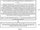
- FIG. 1 is a flowchart of a method for feeding back a precoding matrix indicator according to an embodiment of the present invention. The method is executed by a receive end.
- the multi-antenna system refers to a system in which the transmit end (such as a base station) and the receive end (such as UE) perform communication by using multiple antennas.
- multiple antennas of the transmit end and the receive end can form a spatial diversity gain or multiplexing gain, which can effectively improve the transmission reliability and the system capacity.
- the diversity gain and the multiplexing gain of the multi-antenna system may generally be obtained by using a precoding method of the transmit end and a receive signal combination algorithm of the receive end. For example, in an LTE system, a transmit end uses four antennas, and a receive end uses two antennas.
- the multi-antenna system of this embodiment of the present invention is also applicable to a scenario of multi-point joint transmission, and the multi-point joint transmission refers to that multiple transmit ends perform joint signal transmission for a same user, for example, a transmit end A has two antennas, a transmit end B also has two antennas, and the two transmit ends perform joint transmission for a receive end at the same time. Then, a signal received by the receive end may be considered as a signal sent by a 4-antenna base station.
- the receive end selects the precoding matrix W from the codebook based on the reference signal, where W ⁇ X 1 ⁇ 1 X 2 ⁇ 2 , ⁇ n , and ⁇ 1 and ⁇ 2 respectively indicate the phase difference of the weighted values for the signal transmission between the two neighboring antennas in the first antenna group and the phase difference of the weighted values for the signal transmission between the two neighboring antennas in the second antenna group, where the signal transmission between the two neighboring antennas in the first antenna group and the signal transmission between the two neighboring antennas in the second antenna group are for the same transmission layer.
- an appropriate precoding matrix may be selected according to an antenna spacing condition, to ensure a weak correlation between antennas, and therefore, the transmit end performs precoding based on the precoding matrix fed back by the receive end and selected from a codebook structure of the present invention, to effectively improve the precoding precision, thereby reducing the performance loss, and improving the system throughput.
- a transmit end is a base station
- description is made by using an example in which a receive end is UE
- this is not limited in this embodiment of the present invention, the receive end may be a base station, and the transmit end may be UE.
- the reference signal in 101 may be a channel state information reference signal (Channel State Information Reference Signal, CSI RS), a demodulation reference signal (Demodulation RS, DM RS) or a cell-specific reference signal (Cell-specific RS, CRS), and CSI may further include a channel quality indicator (channel Quality Indicator/Index, CQI for short).
- CSI Channel State Information Reference Signal
- Demodulation RS demodulation reference signal
- DM RS demodulation reference signal
- Cell-specific RS cell-specific reference signal
- CQI channel Quality Indicator/Index
- the UE may obtain a resource configuration of the reference signal by receiving notification (such as radio resource control (Radio Resource Control, RRC) signaling or downlink control information (Downlink Control Information, DCI)) of the base station or based on a cell identity ID and obtain the reference signal in a corresponding resource or subframe.
- notification such as radio resource control (Radio Resource Control, RRC) signaling or downlink control information (Downlink Control Information, DCI)
- RRC Radio Resource Control
- DCI Downlink Control Information
- the receive end may obtain a channel estimation value based on the reference signal, and calculate a channel capacity or throughput or chordal distance based on the channel estimation value, and select the precoding matrix from the codebook according to a criterion pre-defined by the receive end, such as a channel capacity or throughput maximization criterion or a chordal distance minimization criterion.
- a criterion pre-defined by the receive end such as a channel capacity or throughput maximization criterion or a chordal distance minimization criterion.
- the receive end may further determine a rank indicator RI based on the reference signal, where the rank indicator RI is corresponding to a quantity of useful transmission layers.
- the UE may obtain the RI based on a quantity of ports of the reference signal and a unique value of an allowable RI corresponding to a codebook subset limitation; or the UE obtains a channel estimation value based on the reference signal, and calculates a measurement value such as a channel capacity or a throughput based on the channel estimation value, a value for each allowable rank indicator RI, and a corresponding precoding matrix; and selects a rank indicator RI enabling the measurement value to be optimal to serve as a determined rank indicator RI.
- the receive end may select the precoding matrix W corresponding to the rank indicator from the codebook based on the reference signal. Specifically, a codebook subset corresponding to the rank indicator may be determined from the codebook, and then the precoding matrix W is selected from the codebook subset; the precoding matrix W may be further determined directly by using the rank indicator.
- the codebook subset may be pre-defined, or the receive end reports the codebook to the transmit end, and the transmit end determines the codebook subset and notifies the receive end of the codebook subset; or the receive end determines and reports the codebook subset, for example, the codebook subset limitation may be notified by the base station to the UE by using high-layer signaling, such as RRC signaling.
- the UE may send the precoding matrix indicator PMI to the base station by using a physical uplink control channel (Physical Uplink Control Channel, PUCCH) or physical uplink shared channel (Physical Uplink Shared Channel, PUSCH). It should be understood that this is not limited in this embodiment of the present invention.
- PUCCH Physical Uplink Control Channel
- PUSCH Physical Uplink Shared Channel
- the precoding matrix indicator PMI and the rank indicator RI may be sent in a same subframe, and may also be sent in different subframes.
- the matrix X 1 may be further determined according to ⁇ 1 and other factors (such as an amplitude), that is, X 1 is determined according to at least ⁇ 1 ; similarly, the matrix X 2 is determined according to at least ⁇ 2 and ⁇ n , and this is not limited in the present invention.
- the precoding matrix W and the rank indicator are corresponding to each other, and the rank indicator is corresponding to a quantity of useful transmission layers.
- ⁇ 1 and ⁇ 2 may respectively indicate a phase difference of weighted values for signal transmission between two neighboring antennas in the first antenna group and a phase difference of weighted values for signal transmission between two neighboring antennas in the second antenna group, where the signal transmission between the two neighboring antennas in the first antenna group and the signal transmission between the two neighboring antennas in the second antenna group are for any transmission layer of multiple transmission layers.
- the codebook in the present invention may further be a codebook whose rank indicator is another value.
- description is made by using a codebook with a rank indicator of 1 and a codebook with a rank indicator of 2 as an example, and it should be understood that this is not limited in the present invention.
- codebook is indicated in a form of a single-codebook structure, and certainly, may also be indicated in a form of a double-codebook structure, and this is not limited in the present invention.
- this embodiment of the present invention description is made by using a scenario of four antennas as an example, the four antennas are divided into two antenna groups, and each group includes two antennas. It should be understood that this is not limited in this embodiment of the present invention, for example, this embodiment of the present invention may be further applied to a scenario of eight antennas.
- each antenna group of two antenna groups may include four antennas, where
- Y 1 ⁇ 1 0 0 0 , 0 1 0 0 , 0 0 1 0 , 0 0 0 1 , Y 2 ⁇ 1 0 0 0 , 0 1 0 0 , 0 0 1 0 , 0 0 0 1 , and Y1 and Y2 may be the same or different.
- the receive end may send a first precoding matrix indicator PMI 1 and a second precoding matrix indicator PMI 2 to the transmit end, that is, the precoding matrix indicator PMI includes PMI 1 and PMI 2 .
- PMI 1 and PMI 2 are sent in a same period of time or different periods of time.
- PMI 1 is used to indicate W 1
- PMI 2 is used to indicate W 2 1 or W 2 2 .
- PMI 1 and PMI 2 may have a same time-domain or frequency-domain granularity or different time-domain or frequency-domain granularities (or be based on different subframe periods or subband sizes).
- W 1 is a matrix indicating a broadband channel characteristic
- both W 2 1 and W 2 2 are matrices indicating a subband channel characteristic
- W 1 is a matrix indicating a long-term channel characteristic
- both W 2 1 and W 2 2 are matrices indicating a short-term channel characteristic.
- a digital of a superscript in W 2 indicates a value of a rank.
- the receive end may send PMI 1 to the transmit end at a long time interval, and send PMI 2 to the transmit end at a short time interval.
- the receive end may directly indicate a selected precoding matrix W by using a PMI, for example, a codebook totally has 256 precoding matrices, and when the PMI sent by the receive end is 0, a first precoding matrix of the 256 precoding matrices is indicated to the transmit end; when the PMI sent by the receive end is 1, a second precoding matrix of the 256 precoding matrices is indicated to the transmit end, ..., that is, values 0 to 255 of the PMI are respectively corresponding to corresponding precoding matrices of the 256 precoding matrices.
- a manner of indicating a precoding matrix by the receive end is not limited in this embodiment of the present invention.
- the receive end may send a precoding matrix indicator PMI to the transmit end by using a physical control channel or physical shared channel.
- the UE may send a precoding matrix indicator PMI to the base station by using a physical uplink control channel or physical uplink shared channel. It should be understood that this is not limited in this embodiment of the present invention.
- a column vector is selected independently from the matrix X separately by using the column selection vectors Y1 and Y2 in this embodiment of the present invention, thereby ensuring a weak correlation between codebooks corresponding to antennas with a large spacing.
- N 2 k
- the k is a non-negative integer
- M is a positive integer less than N
- i 1 is a non-negative integer less than (N/A-1)
- both i 2 and i 3 are positive integers
- i 2 and i 3 are independent from each other
- ⁇ is a round-down operation symbol.
- N is 2 raised to the power, and may be a value of 0, 2, 4, 8, ..., and the like, P ⁇ ⁇ 0,1,..., N -1 ⁇ , and i 1 ⁇ ⁇ 0,1,..., N / A -1 ⁇ .
- the receive end may send a third precoding matrix indicator PMI 3 and a fourth precoding matrix indicator PMI 4 to the transmit end, that is, the precoding matrix indicator PMI includes PMI 3 and PMI 4 .
- PMI 3 and PMI 4 are sent in a same period of time or different periods of time.
- PMI 3 is used to indicate i 1
- PMI 4 is used to indicate i 2 and i 3 .
- PMI 4 may be a joint coding value of i 2 and i 3 .
- the transmit end may determine i 2 and i 3 by using a value of PMI 4 and a correspondence between i 2 and i 3 .
- PMI 3 and PMI 4 may have different time-domain or frequency-domain granularities.
- the receive end may directly indicate a selected precoding matrix W by using a PMI.
- the receive end may send a precoding matrix indicator PMI to the transmit end by using a physical control channel or physical shared channel. It should be understood that this is not limited in this embodiment of the present invention.
- ⁇ 1 and ⁇ 2 may be selected independently according to a current channel characteristic by using i 2 and i 3 respectively, thereby ensuring a weak correlation between codebooks corresponding to antennas with a large spacing.
- N 2 k
- k a non-negative integer
- A is a positive integer that can be divided exactly by N
- P is a positive integer less than N
- i 1 is a non-negative integer less than (N/A-1)
- ⁇ is a round-down operation symbol
- mod is a modulo operation symbol.
- N is 2 raised to the power, and may be a value of 0, 2, 4, 8, ..., and the like, P ⁇ ⁇ 0,1,..., N -1 ⁇ , and i 1 ⁇ ⁇ 0,1,..., N / A -1 ⁇ .
- the receive end may send a fifth precoding matrix indicator PMI 5 and a sixth precoding matrix indicator PMI 6 to the transmit end, that is, the precoding matrix indicator PMI includes PMI 5 and PMI 2 . Further, PMI 5 and PMI 6 are sent in a same period of time or different periods of time. PMI 5 is used to indicate i 1 , and PMI 6 is used to indicate i 4 . In other words, PMI 5 and PMI 6 may have different time-domain or frequency-domain granularities. Certainly, the receive end may directly indicate a selected precoding matrix W by using a PMI. For a specific implementation manner, reference may be made to the foregoing embodiment, and details are not described herein again.
- the receive end may send a precoding matrix indicator PMI to the transmit end by using a physical control channel or physical shared channel. It should be understood that this is not limited in this embodiment of the present invention.
- ⁇ 1 and ⁇ 2 may be determined according to a current channel characteristic by using i 4 , and ⁇ 1 and ⁇ 2 in the selected precoding matrix may be the same or different, thereby ensuring a weak correlation between codebooks corresponding to antennas with a large spacing.
- the receive end may select a precoding matrix W from a codebook according to selection of ⁇ 1 and ⁇ ⁇ (such as a current channel characteristic).
- the receive end may send two precoding matrix indicators to the transmit end, to indicate ⁇ 1 and ⁇ ⁇ respectively.
- the two precoding matrix indicators may also be sent in a same period of time or different periods of time, and in other words, the two precoding matrix indicators may have different time-domain or frequency-domain granularities.
- the receive end may directly indicate a selected precoding matrix W by using a PMI.
- the receive end may send a precoding matrix indicator PMI to the transmit end by using a physical control channel or physical shared channel. It should be understood that this is not limited in this embodiment of the present invention.
- ⁇ ⁇ may be controlled within a limited change range according to a current channel characteristic, thereby ensuring a weak correlation between codebooks corresponding to antennas with a large spacing.
- N is 2 raised to the power, and may be a value of 0, 2, 4, 8, ..., and the like, m 1 ⁇ ⁇ 0,1,..., N -1 ⁇ , and P ⁇ ⁇ 0,1,..., N -1 ⁇ .
- each of Y, Y 1 ' and Y 2 ' may be one of the following column vectors: 1 0 0 0 , 0 1 0 0 , 0 0 1 0 and 0 0 0 1 .
- the receive end may send a seventh precoding matrix indicator PMI 7 and an eighth precoding matrix indicator PMI 8 to the transmit end, that is, the precoding matrix indicator PMI includes PMI 7 and PMI 8 .
- PMI 7 and PMI 8 are sent in a same period of time or different periods of time.
- PMI 5 is used to indicate W 3
- PMI 8 is used to indicate W 4 1 .
- PMI 7 and PMI 8 may have a same time-domain or frequency-domain granularity or different time-domain or frequency-domain granularities (or be based on different subframe periods or subband sizes).
- W 3 is a matrix indicating a broadband channel characteristic
- W 4 1 is a matrix indicating a subband channel characteristic
- W 3 is a matrix indicating a long-term channel characteristic
- W 4 1 is a matrix indicating a short-term channel characteristic.
- the receive end may send PMI 7 to the transmit end at a long time interval, and send PMI 8 to the transmit end at a short time interval.
- D 1 0 0 e j ⁇ ′ , n 1 ,n 2 ,..., n P are all integers, and may be consecutive values or non-consecutive values
- Y 3 and Y 4 are all P ⁇ 1-dimensional column selection vectors
- N 2 k
- k is a non-negative
- N is 2 raised to the power, and may be a value of 0, 2, 4, 8, ..., and the like, m 1 ⁇ ⁇ 0,1,..., N -1 ⁇ , and P ⁇ ⁇ 0,1,..., N- 1 ⁇ .
- ⁇ 1 specifically indicates a phase difference of weighted values for signal transmission between two neighboring antennas in the first antenna group of the transmit end, where the signal transmission between the two neighboring antennas in the first antenna group is for a first transmission layer of two transmission layers
- ⁇ 2 specifically indicates a phase difference of weighted values for signal transmission between two neighboring antennas in the second antenna group of the transmit end, where the signal transmission between the two neighboring antennas in the second antenna group is for the first transmission layer of the two transmission layers
- ⁇ 3 indicates a phase difference of weighted values for signal transmission between two neighboring antennas in the first antenna group of the transmit end, where the signal transmission between the two neighboring antennas in the first antenna group is for a second transmission layer of the two transmission layers
- ⁇ 4 indicates a phase difference of weighted values for signal transmission between two neighboring antennas in the second antenna group of the transmit end, where the signal transmission between the two neighboring antennas in the second antenna group is for the second transmission layer of the two transmission layers.
- Y 3 and Y 4 may be the same or different, and this is not limited in this embodiment of the present invention.
- l is a positive integer and not an integer multiple of N.
- each of Y 3 and Y 4 may be one of the following column vectors: 1 0 0 0 , 0 1 0 0 , 0 0 1 0 and 0 0 0 1 .
- the receive end may send a ninth precoding matrix indicator PMI 9 and a tenth precoding matrix indicator PMI 10 to the transmit end, that is, the precoding matrix indicator PMI includes PMI 9 and PMI 10 .
- PMI 9 and PMI 10 are sent in a same period of time or different periods of time.
- PMI 9 is used to indicate W 3
- PMI 10 is used to indicate W 4 2 .
- PMI 9 and PMI 10 may have a same time-domain or frequency-domain granularity or different time-domain or frequency-domain granularities (or be based on different subframe periods or subband sizes).
- W 3 is a matrix indicating a broadband channel characteristic
- W 4 2 is a matrix indicating a subband channel characteristic
- W 3 is a matrix indicating a long-term channel characteristic
- W 4 2 is a matrix indicating a short-term channel characteristic.
- the receive end may send PMI 9 to the transmit end at a long time interval, and send PMI 10 to the transmit end at a short time interval.
- the receive end may directly indicate a selected precoding matrix W by using a PMI.
- a PMI for a specific implementation manner, reference may be made to the foregoing embodiment, and details are not described herein again.
- the receive end may send a precoding matrix indicator PMI to the transmit end by using a physical control channel or physical shared channel. It should be understood that this is not limited in this embodiment of the present invention.
- ⁇ ' is selected in this embodiment of the present invention, thereby ensuring a weak correlation between codebooks corresponding to antennas with a large spacing.
- FIG. 2 is a flowchart of a precoding method according to another embodiment of the present invention.
- the method in FIG. 2 is executed by a transmit end, and is corresponding to the method in FIG. 1 , and therefore the description repeated in the embodiment in FIG. 1 is properly omitted.
- a transmit end receives a precoding matrix indicator PMI sent by a receive end, and determines, according to the precoding matrix indicator PMI, a precoding matrix W that is selected by the receive end from a codebook based on a reference signal, where W ⁇ X 1 ⁇ 1 X 2 ⁇ 2 , ⁇ n , and ⁇ 1 and ⁇ 2 respectively indicate the phase difference of the weighted values for the signal transmission between the two neighboring antennas in the first antenna group and the phase difference of the weighted values for the signal transmission between the two neighboring antennas in the second antenna group, where the signal transmission between the two neighboring antennas in the first antenna group and the signal transmission between the two neighboring antennas in the second antenna group are for the same transmission layer.
- an appropriate precoding matrix may be selected according to an antenna spacing condition, to ensure a weak correlation between antennas, and therefore, the transmit end performs precoding based on the precoding matrix fed back by the receive end and selected from a codebook structure of the present invention, to effectively improve the precoding precision, thereby reducing the performance loss, and improving the system throughput.
- the reference signal in step 202 may be a CSI RS, a DM RS or a CRS, and the CSI may further include a channel quality indicator CQI.
- the UE may obtain a resource configuration of the reference signal by receiving a notification (such as RRC signaling or DCI) of the base station or based on a cell identity ID and obtain the reference signal in a corresponding resource or subframe.
- a notification such as RRC signaling or DCI
- the transmit end may receive, by using a physical control channel or physical shared channel, the precoding matrix indicator PMI sent by the receive end.
- the base station may receive, by using a PUCCH or PUSCH, the precoding matrix indicator PMI sent by the UE. It should be understood that this is not limited in this embodiment of the present invention.
- this embodiment of the present invention is applied to a scenario of four antennas, the four antennas are divided into two antenna groups, and each group includes two antennas. It should be understood that this is not limited in this embodiment of the present invention, for example, this embodiments of the present invention may further be applied to a scenario of eight antennas, and for the form of a precoding matrix in the scenario of eight antennas, reference may be made to the foregoing description, and details are not described herein again. For ease of description, in the following example, description is made by using the scenario of four antennas as an example.
- the matrix X 1 may be further determined according to ⁇ 1 and other factors, such as an amplitude, that is, X 1 is determined according to at least ⁇ 1 ; similarly, the matrix X 2 is determined according to at least ⁇ 2 and ⁇ n , and this is not limited in the present invention.
- a precoding matrix W and a rank indicator are corresponding to each other, the rank indicator is corresponding to a quantity of useful transmission layers, the rank indicator may be determined by the receive end, and for a specific example, reference may be made to the foregoing description, and details are not described herein again.
- a precoding matrix whose rank indicator is 1 may be the foregoing formula (1); or, a precoding matrix with a rank indicator of 2 may be the foregoing formula (2).
- the codebook in the present invention may further be a codebook whose rank indicator is another value.
- description is made by using a codebook with a rank indicator of 1 and a codebook with a rank indicator of 2 as an example, and it should be understood that this is not limited in the present invention.
- codebook is indicated in a form of a single-codebook structure, and certainly, may also be indicated in a form of a double-codebook structure, and this is not limited in the present invention.
- step 202 that the rank indicator is 1 or 2 is used as an example, and when the rank indicator is 1, the precoding matrix determined by the transmit end may be the foregoing formula (3); or, when the rank indicator is 2, the precoding matrix determined by the transmit end may be the foregoing formula (4).
- Y 1 ⁇ 1 0 0 0 , 0 1 0 0 , 0 0 1 0 , 0 0 0 1 , Y 2 ⁇ 1 0 0 0 , 0 1 0 0 , 0 0 1 0 , 0 0 0 1 , and Y1 and Y2 may be the same or different.
- the transmit end receives a first precoding matrix indicator PMI 1 and a second precoding matrix indicator PMI 2 sent by the receive end, and the precoding matrix indicator PMI includes PMI 1 and PMI 2 .
- PMI 1 and PMI 2 sent by the receive end are received in a same period of time or different periods of time.
- PMI 1 and PMI 2 may have a same time-domain or frequency-domain granularity or different time-domain or frequency-domain granularities (or be based on different subframe periods or subband sizes).
- the transmit end determines, according to PMI 1 , the W 1 selected by the receive end from the codebook based on the reference signal, and determines, according to PMI 2 , W 2 1 or W 2 2 selected by the UE from the codebook, and the transmit end may determine the precoding matrix W according to W 1 and W 2 1 , or determine the precoding matrix W according to W 1 and W 2 2 .
- W 1 is a matrix indicating a broadband channel characteristic
- both W 2 1 and W 2 2 are matrices indicating a subband channel characteristic
- a digital of a superscript in W 2 indicates a value of a rank
- W 1 is a matrix indicating a long-term channel characteristic
- both W 2 1 and W 2 2 are matrices indicating a short-term channel characteristic.
- the transmit end may receive, at a long time interval, PMI 1 sent by the receive end, and receive, at a short time interval, PMI 2 sent by the receive end.
- the transmit end may directly determine a selected precoding matrix W by using a PMI sent by the receive end.
- a codebook totally has 256 precoding matrices, and when the PMI sent by the receive end and received by the transmit end is 0, the transmit end determines that what is selected by the receive end is a first precoding matrix of the 256 precoding matrices of the codebook, and when the PMI sent by the receive end and received by the transmit end is 1, the transmit end determines that what is selected by the receive end is a second precoding matrix of the 256 precoding matrices of the codebook, ..., that is, values 0 to 255 of the PMI are respectively corresponding to corresponding precoding matrices of the 256 precoding matrices.
- a manner in which the UE indicates a precoding matrix is not limited in this embodiment of the present invention.
- the transmit end may receive, by using a physical control channel or physical shared channel, the precoding matrix indicator PMI sent by the receive end. It should be understood that this is not limited in this embodiment of the present invention.
- a column vector is selected independently from the matrix X separately by using the column selection vectors Y1 and Y2 in this embodiment of the present invention, thereby ensuring a weak correlation between codebooks corresponding to antennas with a large spacing.
- N is 2 raised to the power, and may be a value of 0, 2, 4, 8, ..., and the like, P ⁇ ⁇ 0,1, ⁇ , N -1 ⁇ , and i 1 ⁇ ⁇ 0,1, ⁇ , N / A- 1 ⁇ .
- the transmit end receives a third precoding matrix indicator PMI 3 and a fourth precoding matrix indicator PMI 4 sent by the receive end. Further, PMI 3 and PMI 4 sent by the receive end are received in a same period of time or different periods of time.
- the transmit end determines i 1 according to PMI 3 , and determines i 2 and i 3 according to PMI 4 .
- PMI 4 may be a joint coding value of i 2 and i 3 .
- the transmit end may determine i 2 and i 3 by using a value of PMI 4 and a correspondence between i 2 and i 3 .
- PMI 3 and PMI 4 may have different time-domain or frequency-domain granularities.
- the transmit end may directly determine a selected precoding matrix W by using a PMI sent by the receive end.
- the transmit end may receive, by using a physical control channel or physical shared channel, the precoding matrix indicator PMI sent by the receive end. It should be understood that this is not limited in this embodiment of the present invention.
- ⁇ 1 and ⁇ 2 may be selected independently according to a current channel characteristic by using i 2 and i 3 respectively, thereby ensuring a weak correlation between codebooks corresponding to antennas with a large spacing.
- N is 2 raised to the power, and may be a value of 0, 2, 4, 8, ..., and the like, P ⁇ ⁇ 0,1, ⁇ , N- 1 ⁇ , and i 1 ⁇ ⁇ 0,1, ⁇ , N / A -1 ⁇ .
- the transmit end receives a fifth precoding matrix indicator PMI 5 and a sixth precoding matrix indicator PMI 6 sent by the receive end. Further, PMI 5 and PMI 6 sent by the receive end are received in a same period of time or different periods of time.
- i 1 is determined according to PMI 5
- i 4 is determined according to PMI 6 .
- PMI 5 and PMI 6 may have different time-domain or frequency-domain granularities.
- the transmit end may directly determine a selected precoding matrix W by using a PMI sent by the receive end. For a specific implementation manner, reference may be made to the foregoing embodiment, and details are not described herein again.
- the transmit end may receive, by using a physical control channel or physical shared channel, the precoding matrix indicator PMI sent by the receive end. It should be understood that this is not limited in this embodiment of the present invention.
- ⁇ 1 and ⁇ 2 may be determined according to a current channel characteristic by using i 4 , and ⁇ 1 and ⁇ 2 in the selected precoding matrix may be the same or different, thereby ensuring a weak correlation between codebooks corresponding to antennas with a large spacing.
- the transmit end may receive two precoding matrix indicators sent by the receive end, and the two precoding matrix indicators indicate ⁇ 1 and ⁇ ⁇ respectively. Further, the two precoding matrix indicators sent by the receive end may also be received in a same period of time or different periods of time, and in other words, the two precoding matrix indicators may have different time-domain or frequency-domain granularities.
- the transmit end may determine the precoding matrix W by using ⁇ 1 and ⁇ ⁇ . Certainly, the transmit end may directly determine, by using a PMI sent by the receive end, a precoding matrix W selected by the receive end. For a specific implementation manner, reference may be made to the foregoing embodiment, and details are not described herein again.
- the transmit end may receive, by using a physical control channel or physical shared channel, the precoding matrix indicator PMI sent by the receive end. It should be understood that this is not limited in this embodiment of the present invention.
- ⁇ ⁇ may be controlled within a limited change range according to a current channel characteristic, thereby ensuring a weak correlation between codebooks corresponding to antennas with a large spacing.
- the precoding matrix determined by the transmit end may be the foregoing formula (12) or (13).
- the transmit end may receive two precoding matrix indicators: a seventh precoding matrix indicator PMI 7 and an eighth precoding matrix indicator PMI 8 sent by the receive end, and the two precoding matrix indicators indicate PMI 7 and PMI 8 respectively.
- the two precoding matrix indicators sent by the receive end may also be received in a same period of time or different periods of time, and in other words, the two precoding matrix indicators may have different time-domain or frequency-domain granularities.
- step 202 the transmit end determines, according to PMI 7 , W 3 selected by the receive end from the codebook based on the reference signal, and determines, according to PMI 8 , W 4 1 selected by the UE from the codebook, and the transmit end may determine the precoding matrix W according to W 3 and W 4 1 .
- W 3 is a matrix indicating a broadband channel characteristic
- W 4 1 is a matrix indicating a subband channel characteristic
- W 3 is a matrix indicating a long-term channel characteristic
- W 4 1 is a matrix indicating a short-term channel characteristic.
- the receive end may send PMI 7 to the transmit end at a long time interval, and send PMI 8 to the transmit end at a short time interval.
- the precoding matrix determined by the transmit end may be the foregoing formula (14) or (16).
- the transmit end may receive two precoding matrix indicators: a ninth precoding matrix indicator PMI 9 and a tenth precoding matrix indicator PMI 10 sent by the receive end, and the two precoding matrix indicators indicate PMI 9 and PMI 10 respectively. Further, the two precoding matrix indicators sent by the receive end may also be received in a same period of time or different periods of time, and in other words, the two precoding matrix indicators may have different time-domain or frequency-domain granularities.
- step 202 the transmit end determines, according to PMI 9 , W 3 selected by the receive end from the codebook based on the reference signal, and determines, according to PMI 10 , W 4 2 selected by the UE from the codebook, and the transmit end may determine the precoding matrix W according to W 3 and W 4 2 .
- the transmit end may directly determine, by using a PMI sent by the receive end, a precoding matrix W selected by the receive end.
- the transmit end may receive, by using a physical control channel or physical shared channel, the precoding matrix indicator PMI sent by the receive end. It should be understood that this is not limited in this embodiment of the present invention.
- ⁇ ' is selected in this embodiment of the present invention, thereby ensuring a weak correlation between codebooks corresponding to antennas with a large spacing.
- FIG. 3 is a structural block diagram of a receive end according to an embodiment of the present invention.
- the receive end 300 includes a selection unit 301 and a sending unit 302.
- the selection unit 301 is configured to select a precoding matrix W from a codebook based on a reference signal, where the W ⁇ X 1 ⁇ 1 X 2 ⁇ 2 , ⁇ n , a matrix X 1 is determined according to ⁇ 1 , a matrix X 2 is determined according to ⁇ 2 and ⁇ n , ⁇ 1 indicates a phase difference of weighted values for signal transmission between two neighboring antennas in a first antenna group of a transmit end, where the signal transmission between the two neighboring antennas in the first antenna group is for a same transmission layer, ⁇ 2 indicates a phase difference of weighted values for signal transmission between two neighboring antennas in a second antenna group of the transmit end, where the signal transmission between the two neighboring antennas in the second antenna group is for the same transmission layer, ⁇ n indicates a phase difference of weighted values for signal transmission between the first antenna group and the second antenna group, where the signal transmission between the first antenna group and the second antenna group is for a same transmission layer, ⁇
- the sending unit 302 is configured to send a precoding matrix indicator PMI to the transmit end, so that the transmit end determines, according to the PMI, the precoding matrix W selected by the selection unit 301.
- the multi-antenna system refers to a system in which the transmit end and the receive end perform communication by using multiple antennas.
- multiple antennas of the transmit end and the receive end can form a spatial diversity gain or multiplexing gain, which can effectively improve the transmission reliability and the system capacity.
- the diversity gain and the multiplexing gain of the multi-antenna system may generally be obtained by using a precoding method of the transmit end and a receive signal combination algorithm of the receive end. For example, in an LTE system, a transmit end uses four antennas, and a receive end uses two antennas.
- the multi-antenna system of this embodiment of the present invention is also applicable to a scenario of multi-point joint transmission, and the multi-point joint transmission refers to that multiple transmit ends perform joint signal transmission for a same user, for example, a transmit end A has two antennas, a transmit end B also has two antennas, and the two transmit ends perform joint transmission for a receive end at the same time. Then, a signal received by the receive end may be considered as a signal sent by a 4-antenna base station.
- the receive end selects the precoding matrix W from the codebook based on the reference signal, where W ⁇ X 1 ⁇ 1 X 2 ⁇ 2 , ⁇ n , and ⁇ 1 and ⁇ 2 respectively indicate the phase difference of the weighted values for the signal transmission between the two neighboring antennas in the first antenna group and the phase difference of the weighted values for the signal transmission between the two neighboring antennas in the second antenna group, where the signal transmission between the two neighboring antennas in the first antenna group and the signal transmission between the two neighboring antennas in the second antenna group are for the same transmission layer.
- an appropriate precoding matrix may be selected according to an antenna spacing condition, to ensure a weak correlation between antennas, and therefore, the transmit end performs precoding based on the precoding matrix fed back by the receive end and selected from a codebook structure of the present invention, to effectively improve the precoding precision, thereby reducing the performance loss, and improving the system throughput.
- the transmit end may be a base station, and correspondingly, the receive end may be UE; or the transmit end may be UE, and correspondingly, the receive end may be a base station. It should be understood that this is not limited in this embodiment of the present invention.
- the receive end 300 may implement each step of the receive end involved in the method in FIG. 1 to FIG. 2 , which is not described in detail again to avoid repetition.
- the receive end 300 may further include a determining unit 303, and the determining unit 303 is configured to determine a rank indicator based on the reference signal, where the rank indicator is corresponding to a quantity of useful transmission layers.
- the selection unit 301 is specifically configured to select, from the codebook based on the reference signal, a precoding matrix W corresponding to the rank indicator determined by the determining unit 303.
- the precoding matrix selected by the selection unit 301 may be the foregoing formula (1); or, when the rank indicator determined by the determining unit 303 is 2, the precoding matrix selected by the selection unit 301 may be the foregoing formula (2).
- the codebook in the present invention may further be a codebook whose rank indicator is another value.
- description is made by using a codebook with a rank indicator of 1 and a codebook with a rank indicator of 2 as an example, and it should be understood that this is not limited in the present invention.
- codebook is indicated in a form of a single-codebook structure, and certainly, may also be indicated in a form of a double-codebook structure, and this is not limited in the present invention.
- the rank indicator is 1 or 2 is used as an example, and when the rank indicator determined by the determining unit 303 is 1, the precoding matrix selected by the selection unit 301 may be the foregoing formula (3); or, when the rank indicator determined by the determining unit 303 is 2, the precoding matrix selected by the selection unit 301 may be the foregoing formula (4).
- the precoding matrix selected by the selection unit 301 may be the foregoing formula (4).
- W 1 is a matrix indicating a broadband channel characteristic
- both W 2 1 and W 2 2 are matrices indicating a subband channel characteristic
- a digital of a superscript in W 2 indicates a value of a rank
- W 1 is a matrix indicating a long-term channel characteristic
- both W 2 1 and W 2 2 are matrices indicating a short-term channel characteristic.
- the precoding matrix indicator PMI sent by the sending unit 302 may include a first precoding matrix indicator PMI 1 and a second precoding matrix indicator PMI 2 , PMI 1 is used to indicate W 1 , and PMI 2 is used to indicate W 2 1 or W 2 2 .
- the transmit end may receive, at a long time interval, PMI 1 sent by the sending unit 302, and receive, at a short time interval, PMI 2 sent by the sending unit 302.
- a column vector is selected independently from the matrix X separately by using the column selection vectors Y1 and Y2 in this embodiment of the present invention, thereby ensuring a weak correlation between codebooks corresponding to antennas with a large spacing.
- the precoding matrix selected by the selection unit 301 may be the foregoing formula (12) or (13), and for a specific example, reference may be made to the foregoing description, and details are not described herein again.
- W 3 is a matrix indicating a broadband channel characteristic
- W 4 1 is a matrix indicating a subband channel characteristic
- W 3 is a matrix indicating a long-term channel characteristic
- W 4 1 is a matrix indicating a short-term channel characteristic
- the precoding matrix indicator PMI sent by the sending unit 302 may include a seventh precoding matrix indicator PMI 7 and an eighth precoding matrix indicator PMI 8 , PMI 7 is used to indicate W 3 , and PMI 8 is used to indicate W 4 1 .
- PMI 7 and PMI 8 may have a same time-domain or frequency-domain granularity or different time-domain or frequency-domain granularities (or be based on different subframe periods or subband sizes).
- the transmit end may receive, at a long time interval, PMI 7 sent by the sending unit 302, and receive, at a short time interval, PMI 8 sent by the sending unit 302.
- the precoding matrix selected by the selection unit 301 may be the foregoing formula (14) or (16), and for a specific example, reference may be made to the foregoing description, and details are not described herein again.
- W 3 is a matrix indicating a broadband channel characteristic
- W 4 2 is a matrix indicating a subband channel characteristic
- W 3 is a matrix indicating a long-term channel characteristic
- W 4 2 is a matrix indicating a short-term channel characteristic
- the precoding matrix indicator PMI sent by the sending unit 302 may include a ninth precoding matrix indicator PMI 9 and a tenth precoding matrix indicator PMI 10 , PMI 9 is used to indicate W 3 , and PMI 10 is used to indicate W 4 2 .
- the transmit end may receive, at a long time interval, PMI 9 sent by the sending unit 302, and receive, at a short time interval, PMI 10 sent by the sending unit 302.
- ⁇ ' is selected in this embodiment of the present invention, thereby ensuring a weak correlation between codebooks corresponding to antennas with a large spacing.
- N is 2 raised to the power, and may be a value of 0, 2, 4, 8, ..., and the like, P ⁇ ⁇ 0,1, ⁇ , N -1 ⁇ , and i 1 ⁇ ⁇ 0,1, ⁇ , N /A-1 ⁇ .
- the precoding matrix indicator PMI sent by the sending unit 302 may include a third precoding matrix indicator PMI 3 and a fourth precoding matrix indicator PMI 4 , PMI 3 is used to indicate i 1 , PMI 4 is used to indicate i 2 and i 3 , and specifically, PMI 4 may be a joint coding value of i 2 and i 3 .
- the transmit end may determine i 2 and i 3 by using a value of PMI 4 and a correspondence between i 2 and i 3 .
- ⁇ 1 and ⁇ 2 may be selected independently according to a current channel characteristic by using i 2 and i 3 respectively, thereby ensuring a weak correlation between codebooks corresponding to antennas with a large spacing.
- N is 2 raised to the power, and may be a value of 0, 2, 4, 8, ..., and the like, P ⁇ ⁇ 0,1, ⁇ , N -1 ⁇ , and i 1 ⁇ ⁇ 0,1, ⁇ , N /A-1 ⁇ .
- the precoding matrix indicator PMI sent by the sending unit 302 may include a fifth precoding matrix indicator PMI 5 and a sixth precoding matrix indicator PMI 6 , the PMI 5 is used to indicate i 1 , and PMI 6 is used to indicate i 4 .
- ⁇ ⁇ may be controlled within a limited change range according to a current channel characteristic, thereby ensuring a weak correlation between codebooks corresponding to antennas with a large spacing.
- the selection unit 301 may be further configured to perform row displacement or column displacement on the precoding matrix W according to a serial number of an antenna.
- the receive end 300 may further include a receiving unit 304, and the receiving unit 304 is configured to receive the reference signal sent by the transmit end.
- the determining unit 303 is specifically configured to determine a rank indicator based on the reference signal received by the receiving unit 304; or, the selection unit 301 is specifically configured to select the precoding matrix W from the codebook based on the reference signal received by the receiving unit 304.
- the reference signal includes at least one of the following: a CSI RS, a DM RS and a CRS.
- FIG. 4 is a structural block diagram of a transmit end according to an embodiment of the present invention.
- the transmit end 400 in FIG. 4 includes a receiving unit 401 and a determining unit 402.
- the receiving unit 401 is configured to receive a precoding matrix indicator PMI sent by a receive end.
- the determining unit 402 is configured to determine, according to the precoding matrix indicator PMI received by the receiving unit 401, a precoding matrix W that is selected by the receive end from a codebook based on a reference signal, where W ⁇ X 1 ⁇ 1 X 2 ⁇ 2 , ⁇ n , a matrix X 1 is determined according to ⁇ 1 , a matrix X 2 is determined according to ⁇ 2 and ⁇ n , ⁇ 1 indicates a phase difference of weighted values for signal transmission between two neighboring antennas in a first antenna group of the transmit end, where the signal transmission between the two neighboring antennas in the first antenna group is for a same transmission layer, ⁇ 2 indicates a phase difference of weighted values for signal transmission between two neighboring antennas in a second antenna group of the transmit end, where the signal transmission between the two neighboring antennas in the second antenna group is for the same transmission layer, ⁇ n indicates a phase difference of weighted values for signal transmission between the first antenna group and the second antenna group,
- a transmit end receives a precoding matrix indicator PMI sent by a receive end, and determines, according to the precoding matrix indicator PMI, a precoding matrix W that is selected by the receive end from a codebook based on a reference signal, where W ⁇ X 1 ⁇ 1 X 2 ⁇ 2 , ⁇ n , and ⁇ 1 and ⁇ 2 respectively indicate the phase difference of the weighted values for the signal transmission between the two neighboring antennas in the first antenna group and the phase difference of the weighted values for the signal transmission between the two neighboring antennas in the second antenna group, where the signal transmission between the two neighboring antennas in the first antenna group and the signal transmission between the two neighboring antennas in the second antenna group are for the same transmission layer.
- an appropriate precoding matrix may be selected according to an antenna spacing condition, to ensure a weak correlation between antennas, and therefore, the transmit end performs precoding based on the precoding matrix fed back by the receive end and selected from a codebook structure of the present invention, to effectively improve the precoding precision, thereby reducing the performance loss, and improving the system throughput.
- the transmit end 400 may implement each step of the transmit end involved in the method in FIG. 1 to FIG. 2 , which is not described in detail again to avoid repetition.
- the precoding matrix W and the rank indicator are corresponding to each other, and the rank indicator is corresponding to a quantity of useful transmission layers.
- a codebook with a rank indicator of 1 may be the foregoing formula (1); or, a codebook with a rank indicator of 2 may be the foregoing formula (2).
- the codebook in the present invention may further be a codebook whose rank indicator is another value.
- description is made by using a codebook with a rank indicator of 1 and a codebook with a rank indicator of 2 as an example, and it should be understood that this is not limited in the present invention.
- codebook is indicated in a form of a single-codebook structure, and certainly, may also be indicated in a form of a double-codebook structure, and this is not limited in the present invention.
- the rank indicator is 1 or 2 is used as an example, and when the rank indicator is 1, the precoding matrix determined by the determining unit 402 may be the foregoing formula (3); or, when the rank indicator is 2, the precoding matrix determined by the determining unit 402 may be the foregoing formula (4).
- the precoding matrix determined by the determining unit 402 may be the foregoing formula (3); or, when the rank indicator is 2, the precoding matrix determined by the determining unit 402 may be the foregoing formula (4).
- the precoding matrix indicator PMI that the receiving unit 401 may be specifically configured to receive may include a first precoding matrix indicator PMI 1 and a second precoding matrix indicator PMI 2 .
- PMI 1 and PMI 2 may have a same time-domain or frequency-domain granularity or different time-domain or frequency-domain granularities (or be based on different subframe periods or subband sizes).
- the receiving unit 401 may be specifically configured to receive, at a long time interval, PMI 1 sent by the receive end, and receive, at a short time interval, PMI 2 sent by the receive end.
- the determining unit 402 may be specifically configured to determine, according to PMI 1 , W 1 selected by the receive end from the codebook based on the reference signal, and determine, according to PMI 2 , W 2 1 or W 2 2 selected by the receive end from the codebook.
- the determining unit 402 may be further specifically configured to determine the precoding matrix W according to W 1 and W 2 1 , or determine the precoding matrix W according to W 1 and W 2 2 .
- W 1 is a matrix indicating a broadband channel characteristic
- both W 2 1 and W 2 2 are matrices indicating a subband channel characteristic
- a digital of a superscript in W 2 indicates a value of a rank
- W 1 is a matrix indicating a long-term channel characteristic
- both W 2 1 and W 2 2 are matrices indicating a short-term channel characteristic.
- the determining unit 402 may be specifically configured to directly determine a selected precoding matrix W by using a PMI sent by the receive end and received by the receiving unit 401.
- a codebook totally has 256 precoding matrices, and when the PMI sent by the receive end and received by the receiving unit 401 is 0, the determining unit 402 determines that what is selected by the receive end is a first precoding matrix of the 256 precoding matrices of the codebook, and when the PMI sent by the receive end and received by the receiving unit 401 is 1, the determining unit 402 determines that what is selected by the receive end is a second precoding matrix of the 256 precoding matrices of the codebook, ..., that is, values 0 to 255 of the PMI are respectively corresponding to corresponding precoding matrices of the 256 precoding matrices.
- a manner in which the UE indicates a precoding matrix is not limited in this embodiment of the present invention.
- the receiving unit 401 of the transmit end 400 may receive, by using a physical control channel or physical shared channel, the precoding matrix indicator PMI sent by the receive end. It should be understood that this is not limited in this embodiment of the present invention.
- a column vector is selected independently from the matrix X separately by using the column selection vectors Y1 and Y2 in this embodiment of the present invention, thereby ensuring a weak correlation between codebooks corresponding to antennas with a large spacing.
- the precoding matrix determined by the determining unit 402 may be the foregoing formula (12) or (13).
- the precoding matrix determined by the determining unit 402 may be the foregoing formula (12) or (13).
- the precoding matrix indicator PMI that the receiving unit 401 may be specifically configured to receive may include a seventh precoding matrix indicator PMI 7 and an eighth precoding matrix indicator PMI 8 .
- PMI 7 and PMI 8 may have a same time-domain or frequency-domain granularity or different time-domain or frequency-domain granularities (or be based on different subframe periods or subband sizes).
- the receiving unit 401 may be specifically configured to receive, at a long time interval, PMI 7 sent by the receive end, and receive, at a short time interval, PMI 8 sent by the receive end.
- the determining unit 402 may be specifically configured to determine, according to PMI 7 , W 1 selected by the receive end from the codebook based on the reference signal, and determine, according to PMI 8 , W 4 1 selected by the receive end from the codebook.
- the determining unit 402 may be further specifically configured to determine the precoding matrix W according to W 1 and W 4 1 .
- W 3 is a matrix indicating a broadband channel characteristic
- W 4 1 is a matrix indicating a subband channel characteristic
- W 3 is a matrix indicating a long-term channel characteristic
- W 4 1 is a matrix indicating a short-term channel characteristic
- the precoding matrix determined by the determining unit 402 may be the foregoing formula (14) or (16).
- the precoding matrix determined by the determining unit 402 may be the foregoing formula (14) or (16).
- the precoding matrix indicator PMI that the receiving unit 401 may be specifically configured to receive may include a ninth precoding matrix indicator PMI 9 and a tenth precoding matrix indicator PMI 10 .
- the receiving unit 401 may be specifically configured to receive, at a long time interval, PMI 9 sent by the receive end, and receive, at a short time interval, PMI 10 sent by the receive end.
- the determining unit 402 may be specifically configured to determine, according to PMI 9 , W 1 selected by the receive end from the codebook based on the reference signal, and determine, according to PMI 10 , W 4 2 selected by the receive end from the codebook.
- the determining unit 402 may be further specifically configured to determine the precoding matrix W according to W 1 and W 4 2 .
- W 3 is a matrix indicating a broadband channel characteristic
- W 4 2 is a matrix indicating a subband channel characteristic
- W 3 is a matrix indicating a long-term channel characteristic
- W 4 2 is a matrix indicating a short-term channel characteristic
- ⁇ is selected in this embodiment of the present invention, thereby ensuring a weak correlation between codebooks corresponding to antennas with a large spacing.
- the receiving unit 401 may be specifically configured to receive a third precoding matrix indicator PMI 3 and a fourth precoding matrix indicator PMI 4 sent by the receive end. Further, PMI 3 and PMI 4 sent by the receive end are received in a same period of time or different periods of time.
- the determining unit 402 may be specifically configured to determine i 1 according to PMI 3 , and determine i 2 and i 3 according to PMI 4 .
- PMI 4 may be a joint coding value of i 2 and i 3
- PMI 4 P ⁇ i 2 + i 3 .
- the determining unit 402 may be specifically configured to determine i 2 and i 3 by using a value of PMI 4 and a correspondence between i 2 and i 3 .
- PMI 3 and PMI 4 may have different time-domain or frequency-domain granularities.
- the determining unit 402 may be specifically configured to directly determine the selected precoding matrix W by using a PMI sent by the receive end and received by the receiving unit 401.
- the foregoing embodiment and details are not described herein again.
- the receiving unit 401 of the transmit end 400 may receive, by using a physical control channel or physical shared channel, the precoding matrix indicator PMI sent by the receive end. It should be understood that this is not limited in this embodiment of the present invention.
- ⁇ 1 and ⁇ 2 may be selected independently according to a current channel characteristic by using i 2 and i 3 respectively, thereby ensuring a weak correlation between codebooks corresponding to antennas with a large spacing.
- the receiving unit 401 may be specifically configured to receive a fifth precoding matrix indicator PMI 5 and a sixth precoding matrix indicator PMI 6 sent by the receive end. Further, PMI 5 and PMI 6 sent by the receive end are received in a same period of time or different periods of time.
- the determining unit 402 may be specifically configured to determine i 1 according to PMI 5 , and determine i4 according to PMI 6 . In other words, PMI 5 and PMI 6 may have different time-domain or frequency-domain granularities.
- the determining unit 402 may be specifically configured to directly determine the selected precoding matrix W by using a PMI sent by the receive end and received by the receiving unit 401. For a specific implementation manner, reference may be made to the foregoing embodiment, and details are not described herein again.
- the receiving unit 401 of the transmit end 400 may receive, by using a physical control channel or physical shared channel, the precoding matrix indicator PMI sent by the receive end. It should be understood that this is not limited in this embodiment of the present invention.
- ⁇ 1 and ⁇ 2 may be determined according to a current channel characteristic by using i 4 , and ⁇ 1 and ⁇ 2 in the selected precoding matrix may be the same or different, thereby ensuring a weak correlation between codebooks corresponding to antennas with a large spacing.
- the receiving unit 401 may be specifically configured to receive two precoding matrix indicators sent by the receive end, and the two precoding matrix indicators indicate ⁇ 1 and ⁇ ⁇ respectively. Further, the two precoding matrix indicators sent by the receive end may also be received in a same period of time or different periods of time, and in other words, the two precoding matrix indicators may have different time-domain or frequency-domain granularities.
- the determining unit 402 may be specifically configured to determine the precoding matrix W by using ⁇ 1 and ⁇ ⁇ . Certainly, the determining unit 402 may be specifically configured to directly determine the selected precoding matrix W by using a PMI sent by the receive end and received by the receiving unit 401. For a specific implementation manner, reference may be made to the foregoing embodiment, and details are not described herein again.
- the receiving unit 401 of the transmit end 400 may receive, by using a physical control channel or physical shared channel, the precoding matrix indicator PMI sent by the receive end. It should be understood that this is not limited in this embodiment of the present invention.
- ⁇ ⁇ may be controlled within a limited change range according to a current channel characteristic, thereby ensuring a weak correlation between codebooks corresponding to antennas with a large spacing.
- the determining unit 402 may be further configured to perform row displacement or column displacement on the precoding matrix W according to a serial number of an antenna.
- the transmit end 400 may further include a sending unit 403, and the sending unit 403 is configured to send the reference signal to the receive end, so that the receive end selects the precoding matrix W from the codebook based on the reference signal.
- the reference signal includes at least one of the following: a CSI RS, a DM RS and a CRS.
- FIG. 5 shows an embodiment of a device, and in the embodiment, the device 500 includes a processor 501, a memory 502, a sender 503 and a receiver 504.
- the processor 501 controls an operation of the device 500, and the processor 501 may be further referred to as a central processing unit (Central Processing Unit, CPU).
- the memory 502 may include a read-only memory and a random access memory, and provide an instruction and data to the processor 501.
- a part of the memory 502 may further include a non-volatile random access memory (NVRAM).
- NVRAM non-volatile random access memory
- the processor 501, the memory 502, the sender 503 and the receiver 504 are coupled together by using a bus system 510, where besides including a data bus, the bus system 510 further includes a power supply bus, a control bus and a state signal bus.
- the bus system 510 further includes a power supply bus, a control bus and a state signal bus.
- various buses are all marked as the bus system 510 in FIG. 5 .
- the foregoing method disclosed in the embodiment of the present invention is applicable to the foregoing device 500.
- the processor 501 may be an integrated circuit chip, and have a signal processing capability.
- steps of the foregoing method may be implemented by using a hardware integrated logic circuit in the processor 501 or an instruction in a form of software.
- FIG. 6 is a structural block diagram of a receive end according to another embodiment of the present invention.
- the receive end 600 includes a processor 601 and a sender 602.
- the processor 601 is configured to select a precoding matrix W from a codebook based on a reference signal, where the W ⁇ X 1 ⁇ 1 X 2 ⁇ 2 , ⁇ n , a matrix X 1 is determined according to ⁇ 1 , a matrix X 2 is determined according to ⁇ 2 and ⁇ n , ⁇ 1 indicates a phase difference of weighted values for signal transmission between two neighboring antennas in a first antenna group of a transmit end, where the signal transmission between the two neighboring antennas in the first antenna group is for a same transmission layer, ⁇ 2 indicates a phase difference of weighted values for signal transmission between two neighboring antennas in a second antenna group of the transmit end, where the signal transmission between the two neighboring antennas in the second antenna group is for the same transmission layer, ⁇ n indicates a phase difference of weighted values for signal transmission between the first antenna group and the second antenna group, where the signal transmission between the first antenna group and the second antenna group is for a same transmission layer, ⁇
- the sender 602 is configured to send a precoding matrix indicator PMI to the transmit end, so that the transmit end determines, according to the PMI, the precoding matrix W selected by the processor 601.
- the multi-antenna system refers to a system in which the transmit end and the receive end perform communication by using multiple antennas.
- multiple antennas of the transmit end and the receive end can form a spatial diversity gain or multiplexing gain, which can effectively improve the transmission reliability and the system capacity.
- the diversity gain and the multiplexing gain of the multi-antenna system may generally be obtained by using a precoding method of the transmit end and a receive signal combination algorithm of the receive end. For example, in an LTE system, a transmit end uses four antennas, and a receive end uses two antennas.
- the multi-antenna system of this embodiment of the present invention is also applicable to a scenario of multi-point joint transmission, and the multi-point joint transmission refers to that multiple transmit ends perform joint signal transmission for a same user, for example, a transmit end A has two antennas, a transmit end B also has two antennas, and the two transmit ends perform joint transmission for a receive end at the same time. Then, a signal received by the receive end may be considered as a signal sent by a 4-antenna base station.
- the receive end selects the precoding matrix W from the codebook based on the reference signal, where W ⁇ X 1 ⁇ 1 X 2 ⁇ 2 , ⁇ n , and ⁇ 1 and ⁇ 2 respectively indicate the phase difference of the weighted values for the signal transmission between the two neighboring antennas in the first antenna group and the phase difference of the weighted values for the signal transmission between the two neighboring antennas in the second antenna group, where the signal transmission between the two neighboring antennas in the first antenna group and the signal transmission between the two neighboring antennas in the second antenna group are for the same transmission layer.
- an appropriate precoding matrix may be selected according to an antenna spacing condition, to ensure a weak correlation between antennas, and therefore, the transmit end performs precoding based on the precoding matrix fed back by the receive end and selected from a codebook structure of the present invention, to effectively improve the precoding precision, thereby reducing the performance loss, and improving the system throughput.
- the transmit end may be a base station, and correspondingly, the receive end may be UE; or the transmit end may be UE, and correspondingly, the receive end may be a base station. It should be understood that this is not limited in this embodiment of the present invention.
- the receive end 600 may implement each step of the receive end involved in the method in FIG. 1 to FIG. 2 , which is not described in detail again to avoid repetition.
- the processor 601 may be further configured to determine a rank indicator based on the reference signal, where the rank indicator is corresponding to a quantity of useful transmission layers.
- the processor 601 is specifically configured to select the precoding matrix W corresponding to the rank indicator from the codebook based on the reference signal.
- the precoding matrix selected by the processor 601 may be the foregoing formula (1); or, when the rank indicator determined by the processor 601 is 2, the precoding matrix selected by the processor 601 may be the foregoing formula (2).
- the codebook in the present invention may further be a codebook whose rank indicator is another value.
- description is made by using a codebook with a rank indicator of 1 and a codebook with a rank indicator of 2 as an example, and it should be understood that this is not limited in the present invention.
- codebook is indicated in a form of a single-codebook structure, and certainly, may also be indicated in a form of a double-codebook structure, and this is not limited in the present invention.
- the rank indicator is 1 or 2 is used as an example, and when the rank indicator determined by the processor 601 is 1, the precoding matrix selected by the processor 601 may be the foregoing formula (3); or, when the rank indicator determined by the processor 601 is 2, the precoding matrix selected by the processor 601 may be the foregoing formula (4).
- the rank indicator determined by the processor 601 is 1, the precoding matrix selected by the processor 601 may be the foregoing formula (3); or, when the rank indicator determined by the processor 601 is 2, the precoding matrix selected by the processor 601 may be the foregoing formula (4).
- W 1 is a matrix indicating a broadband channel characteristic
- both W 2 1 and W 2 2 are matrices indicating a subband channel characteristic
- a digital of a superscript in W 2 indicates a value of a rank
- W 1 is a matrix indicating a long-term channel characteristic
- both W 2 1 and W 2 2 are matrices indicating a short-term channel characteristic.
- the transmit end may receive, at a long time interval, PMI 1 sent by the receive end, and receive, at a short time interval, PMI 2 sent by the receive end.
- the precoding matrix indicator PMI sent by the sender 602 may include a first precoding matrix indicator PMI 1 and a second precoding matrix indicator PMI 2 , PMI 1 is used to indicate W 1 , and PMI 2 is used to indicate W 2 1 or W 2 2 .
- a column vector is selected independently from the matrix X separately by using the column selection vectors Y1 and Y2 in this embodiment of the present invention, thereby ensuring a weak correlation between codebooks corresponding to antennas with a large spacing.
- the precoding matrix selected by the processor 601 may be the foregoing formula (12) or (13), and for a specific example, reference may be made to the foregoing description, and details are not described herein again.
- W 3 is a matrix indicating a broadband channel characteristic
- W 4 1 is a matrix indicating a subband channel characteristic
- W 3 is a matrix indicating a long-term channel characteristic
- W 4 1 is a matrix indicating a short-term channel characteristic
- the precoding matrix indicator PMI sent by the sender 602 may include a seventh precoding matrix indicator PMI 7 and an eighth precoding matrix indicator PMI 8 , PMI 7 is used to indicate W 3 , and PMI 8 is used to indicate W 4 1 .
- PMI 7 and PMI 8 may have a same time-domain or frequency-domain granularity or different time-domain or frequency-domain granularities (or be based on different subframe periods or subband sizes).
- the transmit end may receive, at a long time interval, PMI 7 sent by the sender 602, and receive, at a short time interval, PMI 8 sent by the sender 602.
- the precoding matrix selected by the processor 601 may be the foregoing formula (14) or (16), and for a specific example, reference may be made to the foregoing description, and details are not described herein again.
- W 3 is a matrix indicating a broadband channel characteristic
- W 4 2 is a matrix indicating a subband channel characteristic
- W 3 is a matrix indicating a long-term channel characteristic
- W 4 2 is a matrix indicating a short-term channel characteristic
- the precoding matrix indicator PMI sent by the sender 602 may include a ninth precoding matrix indicator PMI 9 and a tenth precoding matrix indicator PMI 10 , PMI 9 is used to indicate W 3 , and PMI 10 is used to indicate W 4 2 .
- the transmit end may receive, at a long time interval, PMI 9 sent by the sender 602, and receive, at a short time interval, PMI 10 sent by the sender 602.
- ⁇ is selected in this embodiment of the present invention, thereby ensuring a weak correlation between codebooks corresponding to antennas with a large spacing.
- N is 2 raised to the power, and may be a value of 0, 2, 4, 8, ..., and the like, P ⁇ ⁇ 0,1, ⁇ , N -1 ⁇ , and i 1 ⁇ ⁇ 0,1, ⁇ , N / A -1 ⁇ .
- the precoding matrix indicator PMI sent by the sender 602 may include a third precoding matrix indicator PMI 3 and a fourth precoding matrix indicator PMI 4 , PMI 3 is used to indicate i 1 , PMI 4 is used to indicate i 2 and i 3 , and specifically, PMI 4 may be a joint coding value of i 2 and i 3 .
- the transmit end may determine i 2 and i 3 by using a value of PMI 4 and a correspondence between i 2 and i 3 .
- ⁇ 1 and ⁇ 2 may be selected independently according to a current channel characteristic by using i 2 and i 3 respectively, thereby ensuring a weak correlation between codebooks corresponding to antennas with a large spacing.
- N is 2 raised to the power, and may be a value of 0, 2, 4, 8, ..., and the like, P ⁇ ⁇ 0,1, ⁇ , N -1 ⁇ , and i 1 ⁇ ⁇ 0,1, ⁇ , N / A -1 ⁇ .
- the precoding matrix indicator PMI sent by the sender 602 may include a fifth precoding matrix indicator PMI 5 and a sixth precoding matrix indicator PMI 6 , the PMI 5 is used to indicate i 1 , and PMI 6 is used to indicate i 4 .
- ⁇ ⁇ may be controlled within a limited change range according to a current channel characteristic, thereby ensuring a weak correlation between codebooks corresponding to antennas with a large spacing.
- the processor 601 may be further configured to perform row displacement or column displacement on the precoding matrix W according to a serial number of an antenna.
- the receive end 600 may further include a receiver 603, and the receiver 603 is configured to receive the reference signal sent by the transmit end.
- the processor 602 is specifically configured to determine a rank indicator based on the reference signal received by the receiver 603; or, the processor 602 is specifically configured to select the precoding matrix W from the codebook based on the reference signal received by the receiver 304.
- the reference signal includes at least one of the following: a CSI RS, a DM RS and a CRS.
- FIG. 7 is a structural block diagram of a transmit end according to another embodiment of the present invention.
- the transmit end 700 in FIG. 7 includes a receiver 701 and a processor 702.
- the receiver 701 is configured to receive a precoding matrix indicator PMI sent by a receive end.
- the processor 702 is configured to determine, according to the precoding matrix indicator PMI received by the receiver 701, a precoding matrix W that is selected by the receive end from a codebook based on a reference signal, where W ⁇ X 1 ⁇ 1 X 2 ⁇ 2 , ⁇ n , a matrix X 1 is determined according to ⁇ 1 , a matrix X 2 is determined according to ⁇ 2 and ⁇ n , ⁇ 1 indicates a phase difference of weighted values for signal transmission between two neighboring antennas in a first antenna group of the transmit end, where the signal transmission between the two neighboring antennas in the first antenna group is for a same transmission layer, ⁇ 2 indicates a phase difference of weighted values for signal transmission between two neighboring antennas in a second antenna group of the transmit end, where the signal transmission between the two neighboring antennas in the second antenna group is for the same transmission layer, ⁇ n indicates a phase difference of weighted values for signal transmission between the first antenna group and the second antenna group, where the signal transmission
- a transmit end receives a precoding matrix indicator PMI sent by a receive end, and determines, according to the precoding matrix indicator PMI, a precoding matrix W that is selected by the receive end from a codebook based on a reference signal, where W ⁇ X 1 ⁇ 1 X 2 ⁇ 2 , ⁇ n , and ⁇ 1 and ⁇ 2 respectively indicate the phase difference of the weighted values for the signal transmission between the two neighboring antennas in the first antenna group and the phase difference of the weighted values for the signal transmission between the two neighboring antennas in the second antenna group, where the signal transmission between the two neighboring antennas in the first antenna group and the signal transmission between the two neighboring antennas in the second antenna group are for the same transmission layer.
- an appropriate precoding matrix may be selected according to an antenna spacing condition, to ensure a weak correlation between antennas, and therefore, the transmit end performs precoding based on the precoding matrix fed back by the receive end and selected from a codebook structure of the present invention, to effectively improve the precoding precision, thereby reducing the performance loss, and improving the system throughput.
- the transmit end 700 may implement each step of the transmit end involved in the method in FIG. 1 to FIG. 2 , which is not described in detail again to avoid repetition.
- the precoding matrix W and the rank indicator are corresponding to each other, and the rank indicator is corresponding to a quantity of useful transmission layers.
- a codebook with a rank indicator of 1 may be the foregoing formula (1); or, a codebook with a rank indicator of 2 may be the foregoing formula (2).
- the codebook in the present invention may further be a codebook whose rank indicator is another value.
- description is made by using a codebook with a rank indicator of 1 and a codebook with a rank indicator of 2 as an example, and it should be understood that this is not limited in the present invention.
- codebook is indicated in a form of a single-codebook structure, and certainly, may also be indicated in a form of a double-codebook structure, and this is not limited in the present invention.
- the rank indicator is 1 or 2 is used as an example, and when the rank indicator is 1, the precoding matrix determined by the processor 702 may be the foregoing formula (3); or, when the rank indicator is 2, the precoding matrix determined by the processor 702 may be the foregoing formula (4).
- the precoding matrix determined by the processor 702 may be the foregoing formula (3); or, when the rank indicator is 2, the precoding matrix determined by the processor 702 may be the foregoing formula (4).
- the precoding matrix indicator PMI that the receiver 701 may be specifically configured to receive may include a first precoding matrix indicator PMI 1 and a second precoding matrix indicator PMI 2 .
- PMI 1 and PMI 2 may have a same time-domain or frequency-domain granularity or different time-domain or frequency-domain granularities (or be based on different subframe periods or subband sizes).
- the receiver 701 may be specifically configured to receive, at a long time interval, PMI 1 sent by the receive end, and receive, at a short time interval, PMI 2 sent by the receive end.
- the processor 702 may be specifically configured to determine, according to PMI 1 , W 1 selected by the receive end from the codebook based on the reference signal, and determine, according to PMI 2 , W 2 1 or W 2 2 selected by the receive end from the codebook.
- the processor 702 may be further specifically configured to determine the precoding matrix W according to W 1 and W 2 1 , or determine the precoding matrix W according to W 1 and W 2 2 .
- W 1 is a matrix indicating a broadband channel characteristic
- both W 2 1 and W 2 2 are matrices indicating a subband channel characteristic
- a digital of a superscript in W 2 indicates a value of a rank
- W 1 is a matrix indicating a long-term channel characteristic
- both W 2 1 and W 2 2 are matrices indicating a short-term channel characteristic.
- the processor 702 may be specifically configured to directly determine a selected precoding matrix W by using a PMI sent by the receive end and received by the receiver 701.
- a codebook totally has 256 precoding matrices, and when the PMI sent by the receive end and received by the receiver 701 is 0, the processor 702 determines that what is selected by the receive end is a first precoding matrix of the 256 precoding matrices of the codebook, and when the PMI sent by the receive end and received by the receiver 701 is 1, the processor 702 determines that what is selected by the receive end is a second precoding matrix of the 256 precoding matrices of the codebook, ..., that is, values 0 to 255 of the PMI are respectively corresponding to corresponding precoding matrices of the 256 precoding matrices.
- a manner of indicating a precoding matrix by the UE is not limited in this embodiment of the present invention.
- the receiver 701 of the transmit end 700 may receive, by using a physical control channel or physical shared channel, the precoding matrix indicator PMI sent by the receive end. It should be understood that this is not limited in this embodiment of the present invention.
- a column vector is selected independently from the matrix X separately by using the column selection vectors Y1 and Y2 in this embodiment of the present invention, thereby ensuring a weak correlation between codebooks corresponding to antennas with a large spacing.
- the precoding matrix determined by the processor 702 may be the foregoing formula (12) or (13).
- the precoding matrix determined by the processor 702 may be the foregoing formula (12) or (13).
- the precoding matrix indicator PMI that the receiver 701 may be specifically configured to receive may include a seventh precoding matrix indicator PMI 7 and an eighth precoding matrix indicator PMI 8 .
- PMI 7 and PMI 8 may have a same time-domain or frequency-domain granularity or different time-domain or frequency-domain granularities (or be based on different subframe periods or subband sizes).
- the receiver 701 may be specifically configured to receive, at a long time interval, PMI 7 sent by the receive end, and receive, at a short time interval, PMI 8 sent by the receive end.
- the processor 702 may be specifically configured to determine, according to PMI 7 , W 1 selected by the receive end from the codebook based on the reference signal, and determine, according to PMI 8 , W 4 1 selected by the receive end from the codebook.
- the processor 702 may be further specifically configured to determine the precoding matrix W according to W 1 and W 4 1 .
- W 3 is a matrix indicating a broadband channel characteristic
- W 4 1 is a matrix indicating a subband channel characteristic
- W 3 is a matrix indicating a long-term channel characteristic
- W 4 1 is a matrix indicating a short-term channel characteristic
- the precoding matrix determined by the processor 702 may be the foregoing formula (14) or (16).
- the precoding matrix determined by the processor 702 may be the foregoing formula (14) or (16).
- the precoding matrix indicator PMI that the receiver 701 may be specifically configured to receive may include a ninth precoding matrix indicator PMI 9 and a tenth precoding matrix indicator PMI 10 .
- the receiver 701 may be specifically configured to receive, at a long time interval, PMI 9 sent by the receive end, and receive, at a short time interval, PMI 10 sent by the receive end.
- the processor 702 may be specifically configured to determine, according to PMI 9 , W 1 selected by the receive end from the codebook based on the reference signal, and determine, according to PMI 10 , W 4 2 selected by the receive end from the codebook.
- the processor 702 may be further specifically configured to determine the precoding matrix W according to W 1 and W 4 2 .
- W 3 is a matrix indicating a broadband channel characteristic
- W 4 2 is a matrix indicating a subband channel characteristic
- W 3 is a matrix indicating a long-term channel characteristic
- W 4 2 is a matrix indicating a short-term channel characteristic
- ⁇ is selected in this embodiment of the present invention, thereby ensuring a weak correlation between codebooks corresponding to antennas with a large spacing.
- N is 2 raised to the power, and may be a value of 0, 2, 4, 8, ..., and the like, P ⁇ ⁇ 0,1, ⁇ , N -1 ⁇ , and i 1 ⁇ ⁇ 0,1, ⁇ , N / A -1 ⁇ .
- the receiver 701 may be specifically configured to receive a third precoding matrix indicator PMI 3 and a fourth precoding matrix indicator PMI 4 sent by the receive end. Further, PMI 3 and PMI 4 sent by the receive end are received in a same period of time or different periods of time.
- the processor 702 may be specifically configured to determine i 1 according to PMI 3 , and determine i 2 and i 3 according to PMI 4 .
- PMI 4 may be a joint coding value of i 2 and i 3
- PMI 4 P ⁇ i 2 + i 3 .
- the processor 702 may be specifically configured to determine i 2 and i 3 by using a value of PMI 4 and a correspondence between i 2 and i 3 .
- PMI 3 and PMI 4 may have different time-domain or frequency-domain granularities.
- the processor 702 may be specifically configured to directly determine the selected precoding matrix W by using a PMI sent by the receive end and received by the receiver 701.
- PMI sent by the receive end and received by the receiver 701.
- the receiver 701 of the transmit end 700 may receive, by using a physical control channel or physical shared channel, the precoding matrix indicator PMI sent by the receive end. It should be understood that this is not limited in this embodiment of the present invention.
- ⁇ 1 and ⁇ 2 may be selected independently according to a current channel characteristic by using i 2 and i 3 respectively, thereby ensuring a weak correlation between codebooks corresponding to antennas with a large spacing.
- N is 2 raised to the power, and may be a value of 0, 2, 4, 8, ..., and the like, P ⁇ ⁇ 0,1, ⁇ , N -1 ⁇ , and i 1 ⁇ ⁇ 0,1, ⁇ , N / A -1 ⁇ .
- the receiver 701 may be specifically configured to receive a fifth precoding matrix indicator PMI 5 and a sixth precoding matrix indicator PMI 6 sent by the receive end. Further, PMI 5 and PMI 6 sent by the receive end are received in a same period of time or different periods of time.
- the processor 702 may be specifically configured to determine i 1 according to PMI 5 , and determine i4 according to PMI 6 . In other words, PMI 5 and PMI 6 may have different time-domain or frequency-domain granularities.
- the processor 702 may be specifically configured to directly determine the selected precoding matrix W by using a PMI sent by the receive end and received by the receiver 701. For a specific implementation manner, reference may be made to the foregoing embodiment, and details are not described herein again.
- the receiver 701 of the transmit end 700 may receive, by using a physical control channel or physical shared channel, the precoding matrix indicator PMI sent by the receive end. It should be understood that this is not limited in this embodiment of the present invention.
- ⁇ 1 and ⁇ 2 may be determined according to a current channel characteristic by using i 4 , and ⁇ 1 and ⁇ 2 in the selected precoding matrix may be the same or different, thereby ensuring a weak correlation between codebooks corresponding to antennas with a large spacing.
- the receiver 701 may be specifically configured to receive two precoding matrix indicators sent by the receive end, and the two precoding matrix indicators indicate ⁇ 1 and ⁇ ⁇ respectively. Further, the two precoding matrix indicators sent by the receive end may also be received in a same period of time or different periods of time, and in other words, the two precoding matrix indicators may have different time-domain or frequency-domain granularities.
- the processor 702 may be specifically configured to determine the precoding matrix W by using ⁇ 1 and ⁇ ⁇ . Certainly, the processor 702 may be specifically configured to directly determine the selected precoding matrix W by using a PMI sent by the receive end and received by the receiver 701. For a specific implementation manner, reference may be made to the foregoing embodiment, and details are not described herein again.
- the receiver 701 of the transmit end 700 may receive, by using a physical control channel or physical shared channel, the precoding matrix indicator PMI sent by the receive end. It should be understood that this is not limited in this embodiment of the present invention.
- ⁇ ⁇ may be controlled within a limited change range according to a current channel characteristic, thereby ensuring a weak correlation between codebooks corresponding to antennas with a large spacing.
- the processor 702 may be further configured to perform row displacement or column displacement on the precoding matrix W according to a serial number of an antenna.
- the transmit end 700 may further include a sender 703, and the sender 703 is configured to send the reference signal to the receive end, so that the receive end selects the precoding matrix W from the codebook based on the reference signal.
- the reference signal includes at least one of the following: a CSI RS, a DM RS and a CRS.
- the disclosed system, apparatus, and method may be implemented in other manners.
- the described apparatus embodiment is merely exemplary.
- the unit division is merely logical function division and may be other division in actual implementation.
- a plurality of units or components may be combined or integrated into another system, or some features may be ignored or not performed.
- the displayed or discussed mutual couplings or direct couplings or communication connections may be implemented through some interfaces.
- the indirect couplings or communication connections between the apparatuses or units may be implemented in electronic, mechanical, or other forms.
- the units described as separate parts may or may not be physically separate, and parts displayed as units may or may not be physical units, may be located in one position, or may be distributed on a plurality of network units. A part or all of the units may be selected according to actual needs to achieve the objectives of the solutions of the embodiments.
- functional units in the embodiments of the present invention may be integrated into one processing unit, or each of the units may exist alone physically, or two or more units are integrated into one unit.
- the functions When the functions are implemented in the form of a software functional unit and sold or used as an independent product, the functions may be stored in a computer-readable storage medium. Based on such an understanding, the technical solutions of the present invention essentially, or the part contributing to the prior art, or a part of the technical solutions may be implemented in a form of a software product.
- the software product is stored in a storage medium, and includes several instructions for instructing a computer device (which may be a personal computer, a server, or a network device) to perform all or a part of the steps of the methods described in the embodiments of the present invention.
- the foregoing storage medium includes: any medium that can store program code, such as a USB flash drive, a removable hard disk, a read-only memory (Read-Only Memory, ROM), a random access memory (Random Access Memory, RAM), a magnetic disk, or an optical disc.
- program code such as a USB flash drive, a removable hard disk, a read-only memory (Read-Only Memory, ROM), a random access memory (Random Access Memory, RAM), a magnetic disk, or an optical disc.
Landscapes
- Engineering & Computer Science (AREA)
- Computer Networks & Wireless Communication (AREA)
- Signal Processing (AREA)
- Quality & Reliability (AREA)
- Physics & Mathematics (AREA)
- Mathematical Physics (AREA)
- Radio Transmission System (AREA)
- Mobile Radio Communication Systems (AREA)
Claims (4)
- Procédé de rétroaction d'un indicateur de matrice de précodage, comprenant :la sélection (101), par une extrémité de réception, d'une matrice de précodage W à partir d'un livre de codes sur la base d'un signal de référence,

 l'envoi (102), par l'extrémité de réception, d'un indicateur de matrice de précodage, PMI, à l'extrémité de transmission, de telle sorte que l'extrémité de transmission détermine W en fonction du PMI,caractérisé en ce que
 N = 2k, k étant un nombre entier non négatif, A étant un nombre entier positif qui peut être divisé exactement par N, P étant un nombre entier positif inférieur à N, i1 étant un nombre entier non négatif inférieur à (N/A-1), i4 étant un nombre entier positif inférieur à (PM-1), └·┘ étant un symbole d'opération d'arrondi, mod étant un symbole d'opération modulo.
 - Procédé selon la revendication 1, après la sélection, par une extrémité de réception, d'une matrice de précodage W à partir d'un livre de codes sur la base d'un signal de référence, le procédé comprenant en outre :
la réalisation, par l'extrémité de réception, d'un déplacement de rangée ou d'un déplacement de colonne sur W en fonction d'un numéro de série d'une antenne. - Extrémité de réception comprenant :une unité de sélection (301) configurée pour sélectionner une matrice de précodage W à partir d'un livre de codes sur la base d'un signal de référence,

 une unité d'envoi (302), configurée pour envoyer un indicateur de matrice de précodage, PMI, à l'extrémité de transmission, de telle sorte que l'extrémité de transmission détermine, en fonction du PMI, W sélectionnée par l'unité de sélection,caractérisé en ce que
 N = 2k, k étant un nombre entier non négatif, A étant un nombre entier positif qui peut être divisé exactement par N, P étant un nombre entier positif inférieur à N, i1 étant un nombre entier non négatif inférieur à (N/A-1), i4 étant un nombre entier positif inférieur à (PM-1), └·┘ étant un symbole d'opération d'arrondi, mod étant un symbole d'opération modulo.
 - Extrémité de réception selon la revendication 3, une unité de sélection étant configurée pour, après sélection d'une matrice de précodage W à partir d'un livre de codes sur la base d'un signal de référence, réaliser un déplacement de rangée ou un déplacement de colonne sur W en fonction d'un numéro de série d'une antenne.
Priority Applications (1)
| Application Number | Priority Date | Filing Date | Title |
|---|---|---|---|
| EP18191215.5A EP3484075A1 (fr) | 2013-03-08 | 2013-05-17 | Procédé de rétroaction d'un indicateur matriciel de précodage, d'une extrémité de réception et d'une extrémité d'émission |
Applications Claiming Priority (2)
| Application Number | Priority Date | Filing Date | Title |
|---|---|---|---|
| CN2013072358 | 2013-03-08 | ||
| PCT/CN2013/075834 WO2014134876A1 (fr) | 2013-03-08 | 2013-05-17 | Procédé de rétroaction d'indication de matrice de précodage, et extrémité de réception et extrémité d'émission |
Related Child Applications (2)
| Application Number | Title | Priority Date | Filing Date |
|---|---|---|---|
| EP18191215.5A Division-Into EP3484075A1 (fr) | 2013-03-08 | 2013-05-17 | Procédé de rétroaction d'un indicateur matriciel de précodage, d'une extrémité de réception et d'une extrémité d'émission |
| EP18191215.5A Division EP3484075A1 (fr) | 2013-03-08 | 2013-05-17 | Procédé de rétroaction d'un indicateur matriciel de précodage, d'une extrémité de réception et d'une extrémité d'émission |
Publications (3)
| Publication Number | Publication Date |
|---|---|
| EP2945306A1 EP2945306A1 (fr) | 2015-11-18 |
| EP2945306A4 EP2945306A4 (fr) | 2016-02-24 |
| EP2945306B1 true EP2945306B1 (fr) | 2018-11-07 |
Family
ID=51490600
Family Applications (2)
| Application Number | Title | Priority Date | Filing Date |
|---|---|---|---|
| EP13877003.7A Active EP2945306B1 (fr) | 2013-03-08 | 2013-05-17 | Procédé de rétroaction d'indication de matrice de précodage, et extrémité de réception et extrémité d'émission |
| EP18191215.5A Withdrawn EP3484075A1 (fr) | 2013-03-08 | 2013-05-17 | Procédé de rétroaction d'un indicateur matriciel de précodage, d'une extrémité de réception et d'une extrémité d'émission |
Family Applications After (1)
| Application Number | Title | Priority Date | Filing Date |
|---|---|---|---|
| EP18191215.5A Withdrawn EP3484075A1 (fr) | 2013-03-08 | 2013-05-17 | Procédé de rétroaction d'un indicateur matriciel de précodage, d'une extrémité de réception et d'une extrémité d'émission |
Country Status (3)
| Country | Link |
|---|---|
| US (1) | US9258044B2 (fr) |
| EP (2) | EP2945306B1 (fr) |
| WO (1) | WO2014134876A1 (fr) |
Families Citing this family (8)
| Publication number | Priority date | Publication date | Assignee | Title |
|---|---|---|---|---|
| WO2016015225A1 (fr) * | 2014-07-29 | 2016-02-04 | 华为技术有限公司 | Procédé et dispositif de réception et de renvoi d'informations d'état de canal |
| CN108352870B (zh) * | 2015-11-04 | 2021-07-27 | 瑞典爱立信有限公司 | 对从天线阵列的传输进行预编码的方法和发送无线电节点 |
| WO2017113112A1 (fr) * | 2015-12-29 | 2017-07-06 | 华为技术有限公司 | Procédé et appareil pour déterminer une matrice de précodage |
| CN107888246B (zh) | 2016-09-29 | 2023-04-28 | 华为技术有限公司 | 基于码本的信道状态信息反馈方法及设备 |
| WO2018059567A1 (fr) * | 2016-09-29 | 2018-04-05 | 华为技术有限公司 | Procédé et dispositif de rétroaction d'informations d'état de canal à base de livre de codes |
| CN110380767B (zh) * | 2018-04-13 | 2022-03-25 | 华为技术有限公司 | 一种预编码矩阵确定方法及装置 |
| CN111865377B (zh) | 2019-04-30 | 2022-06-14 | 华为技术有限公司 | 指示和确定预编码矩阵的方法以及通信装置 |
| WO2021043399A1 (fr) * | 2019-09-04 | 2021-03-11 | Telefonaktiebolaget Lm Ericsson (Publ) | Transmission formée en faisceau vers un dispositif émetteur-récepteur radio |
Family Cites Families (19)
| Publication number | Priority date | Publication date | Assignee | Title |
|---|---|---|---|---|
| US7689177B2 (en) * | 2006-05-24 | 2010-03-30 | Samsung Electronics Co., Ltd. | Method and apparatus for transmitting/receiving feedback information and system supporting the same in a multi-user multi-antenna system |
| JP2009152688A (ja) | 2007-12-18 | 2009-07-09 | Toshiba Corp | 端末装置、基地局、無線通信方法および通信プログラム |
| US8676133B2 (en) * | 2008-09-19 | 2014-03-18 | Qualcomm Incorporated | Reference signal design for LTE A |
| EP2351246B1 (fr) | 2008-11-03 | 2017-02-22 | Telefonaktiebolaget LM Ericsson (publ) | Procédé d'émission de signaux de référence et détermination de matrices de précodage pour émission multi-antenne |
| WO2010105415A1 (fr) * | 2009-03-17 | 2010-09-23 | Huawei Technologies Co., Ltd. | Procédé de génération d'un livre de code |
| CN102035626B (zh) * | 2009-09-30 | 2013-06-12 | 华为技术有限公司 | 一种获取预编码矩阵指示的方法和装置 |
| CN102164027B (zh) * | 2010-02-24 | 2014-07-30 | 华为技术有限公司 | 预编码矩阵索引反馈方法和装置 |
| KR101606803B1 (ko) * | 2010-04-29 | 2016-03-28 | 엘지전자 주식회사 | 제어정보의 전송방법 및 기지국과, 제어정보의 수신방법 및 사용자기기 |
| CN102594502B (zh) * | 2010-05-04 | 2015-09-30 | 华为技术有限公司 | 发送预编码矩阵索引及进行预编码的方法和装置 |
| CN102291199B (zh) | 2010-06-18 | 2013-11-20 | 电信科学技术研究院 | 一种上报信道状态信息的方法及装置 |
| US8885754B2 (en) * | 2010-07-29 | 2014-11-11 | Lg Electronics Inc. | Method and device for sending and receiving precoded signals on a wireless communication system |
| EP2665211A4 (fr) * | 2011-01-10 | 2015-08-12 | Lg Electronics Inc | Procédé et dispositif d'émission/réception de signal de référence de liaison descendante dans un système de communication sans fil |
| EP2702699A1 (fr) * | 2011-04-27 | 2014-03-05 | Fujitsu Limited | Communication sans fil avec des cellules coopératives |
| EP2820773B1 (fr) * | 2012-03-02 | 2017-12-27 | Telefonaktiebolaget LM Ericsson (publ) | Station de base radio et procédé à l'intérieur de cette dernière permettant de transformer un signal de transmission de données |
| CN104412520B (zh) * | 2012-06-24 | 2017-11-21 | Lg电子株式会社 | 在无线通信系统中报告信道状态信息的方法和装置 |
| US9252852B2 (en) * | 2012-07-09 | 2016-02-02 | Lg Electronics Inc. | Method for transmitting feedback by using codebook in wireless communication system and apparatus for same |
| WO2014088174A1 (fr) * | 2012-12-03 | 2014-06-12 | 엘지전자 주식회사 | Procédé et appareil pour notifier des informations d'état de canal dans un système de communication sans fil |
| US9503171B2 (en) * | 2013-01-04 | 2016-11-22 | Electronics And Telecommunications Research Institute | Method for transmitting signal using multiple antennas |
| WO2014133589A1 (fr) * | 2013-03-01 | 2014-09-04 | Intel Corporation | Décharge de trafic de réseau local sans-fil (wlan) |
-
2013
- 2013-05-17 EP EP13877003.7A patent/EP2945306B1/fr active Active
- 2013-05-17 EP EP18191215.5A patent/EP3484075A1/fr not_active Withdrawn
- 2013-05-17 WO PCT/CN2013/075834 patent/WO2014134876A1/fr active Application Filing
-
2015
- 2015-09-03 US US14/844,714 patent/US9258044B2/en active Active
Non-Patent Citations (1)
| Title |
|---|
| None * |
Also Published As
| Publication number | Publication date |
|---|---|
| EP2945306A4 (fr) | 2016-02-24 |
| US20150381249A1 (en) | 2015-12-31 |
| EP2945306A1 (fr) | 2015-11-18 |
| WO2014134876A1 (fr) | 2014-09-12 |
| EP3484075A1 (fr) | 2019-05-15 |
| US9258044B2 (en) | 2016-02-09 |
Similar Documents
| Publication | Publication Date | Title |
|---|---|---|
| US9906279B2 (en) | Precoding matrix indicator feedback method, receive end, and transmit end | |
| EP3497808B1 (fr) | Livres de codes à faisceaux multiples avec un surdébit davantage optimisé | |
| US9843366B1 (en) | Method for transmitting 4-antenna precoding matrix, user equipment and base station | |
| EP3557797A1 (fr) | Procédé de communication, station de base et dispositif terminal | |
| EP2945306B1 (fr) | Procédé de rétroaction d'indication de matrice de précodage, et extrémité de réception et extrémité d'émission | |
| EP2930873B1 (fr) | Procédé pour rapporter des informations d'état de canal, équipement utilisateur et station de base | |
| EP2985923B1 (fr) | Procédé de détermination d'indicateur de matrice de précodage, équipement utilisateur et station de base | |
| EP2947787B1 (fr) | Procédé de renvoi d'informations d'état de canal, équipement utilisateur et station de base | |
| CN108599819B (zh) | 预编码矩阵指示的反馈方法、接收端和发射端 | |
| EP3276915B1 (fr) | Procédé et dispositif d'émission de signal | |
| WO2018094709A1 (fr) | Procédé, dispositif, et système de détermination de matrice de précodage |
Legal Events
| Date | Code | Title | Description |
|---|---|---|---|
| PUAI | Public reference made under article 153(3) epc to a published international application that has entered the european phase |
Free format text: ORIGINAL CODE: 0009012 |
|
| 17P | Request for examination filed |
Effective date: 20150813 |
|
| AK | Designated contracting states |
Kind code of ref document: A1 Designated state(s): AL AT BE BG CH CY CZ DE DK EE ES FI FR GB GR HR HU IE IS IT LI LT LU LV MC MK MT NL NO PL PT RO RS SE SI SK SM TR |
|
| AX | Request for extension of the european patent |
Extension state: BA ME |
|
| A4 | Supplementary search report drawn up and despatched |
Effective date: 20160121 |
|
| RIC1 | Information provided on ipc code assigned before grant |
Ipc: H04L 1/00 20060101AFI20160115BHEP Ipc: H04B 7/04 20060101ALI20160115BHEP Ipc: H04B 7/06 20060101ALI20160115BHEP |
|
| DAX | Request for extension of the european patent (deleted) | ||
| STAA | Information on the status of an ep patent application or granted ep patent |
Free format text: STATUS: EXAMINATION IS IN PROGRESS |
|
| 17Q | First examination report despatched |
Effective date: 20171018 |
|
| GRAP | Despatch of communication of intention to grant a patent |
Free format text: ORIGINAL CODE: EPIDOSNIGR1 |
|
| STAA | Information on the status of an ep patent application or granted ep patent |
Free format text: STATUS: GRANT OF PATENT IS INTENDED |
|
| RIC1 | Information provided on ipc code assigned before grant |
Ipc: H04L 1/00 20060101AFI20180508BHEP Ipc: H04B 7/06 20060101ALI20180508BHEP Ipc: H04B 7/04 20170101ALI20180508BHEP Ipc: H04B 7/0456 20170101ALI20180508BHEP |
|
| INTG | Intention to grant announced |
Effective date: 20180528 |
|
| GRAS | Grant fee paid |
Free format text: ORIGINAL CODE: EPIDOSNIGR3 |
|
| GRAA | (expected) grant |
Free format text: ORIGINAL CODE: 0009210 |
|
| STAA | Information on the status of an ep patent application or granted ep patent |
Free format text: STATUS: THE PATENT HAS BEEN GRANTED |
|
| AK | Designated contracting states |
Kind code of ref document: B1 Designated state(s): AL AT BE BG CH CY CZ DE DK EE ES FI FR GB GR HR HU IE IS IT LI LT LU LV MC MK MT NL NO PL PT RO RS SE SI SK SM TR |
|
| REG | Reference to a national code |
Ref country code: GB Ref legal event code: FG4D |
|
| REG | Reference to a national code |
Ref country code: CH Ref legal event code: EP Ref country code: AT Ref legal event code: REF Ref document number: 1063352 Country of ref document: AT Kind code of ref document: T Effective date: 20181115 |
|
| REG | Reference to a national code |
Ref country code: DE Ref legal event code: R096 Ref document number: 602013046501 Country of ref document: DE |
|
| REG | Reference to a national code |
Ref country code: IE Ref legal event code: FG4D |
|
| REG | Reference to a national code |
Ref country code: SE Ref legal event code: TRGR |
|
| REG | Reference to a national code |
Ref country code: NL Ref legal event code: FP |
|
| REG | Reference to a national code |
Ref country code: LT Ref legal event code: MG4D |
|
| REG | Reference to a national code |
Ref country code: AT Ref legal event code: MK05 Ref document number: 1063352 Country of ref document: AT Kind code of ref document: T Effective date: 20181107 |
|
| PG25 | Lapsed in a contracting state [announced via postgrant information from national office to epo] |
Ref country code: ES Free format text: LAPSE BECAUSE OF FAILURE TO SUBMIT A TRANSLATION OF THE DESCRIPTION OR TO PAY THE FEE WITHIN THE PRESCRIBED TIME-LIMIT Effective date: 20181107 Ref country code: LV Free format text: LAPSE BECAUSE OF FAILURE TO SUBMIT A TRANSLATION OF THE DESCRIPTION OR TO PAY THE FEE WITHIN THE PRESCRIBED TIME-LIMIT Effective date: 20181107 Ref country code: NO Free format text: LAPSE BECAUSE OF FAILURE TO SUBMIT A TRANSLATION OF THE DESCRIPTION OR TO PAY THE FEE WITHIN THE PRESCRIBED TIME-LIMIT Effective date: 20190207 Ref country code: AT Free format text: LAPSE BECAUSE OF FAILURE TO SUBMIT A TRANSLATION OF THE DESCRIPTION OR TO PAY THE FEE WITHIN THE PRESCRIBED TIME-LIMIT Effective date: 20181107 Ref country code: FI Free format text: LAPSE BECAUSE OF FAILURE TO SUBMIT A TRANSLATION OF THE DESCRIPTION OR TO PAY THE FEE WITHIN THE PRESCRIBED TIME-LIMIT Effective date: 20181107 Ref country code: IS Free format text: LAPSE BECAUSE OF FAILURE TO SUBMIT A TRANSLATION OF THE DESCRIPTION OR TO PAY THE FEE WITHIN THE PRESCRIBED TIME-LIMIT Effective date: 20190307 Ref country code: LT Free format text: LAPSE BECAUSE OF FAILURE TO SUBMIT A TRANSLATION OF THE DESCRIPTION OR TO PAY THE FEE WITHIN THE PRESCRIBED TIME-LIMIT Effective date: 20181107 Ref country code: BG Free format text: LAPSE BECAUSE OF FAILURE TO SUBMIT A TRANSLATION OF THE DESCRIPTION OR TO PAY THE FEE WITHIN THE PRESCRIBED TIME-LIMIT Effective date: 20190207 Ref country code: HR Free format text: LAPSE BECAUSE OF FAILURE TO SUBMIT A TRANSLATION OF THE DESCRIPTION OR TO PAY THE FEE WITHIN THE PRESCRIBED TIME-LIMIT Effective date: 20181107 |
|
| PG25 | Lapsed in a contracting state [announced via postgrant information from national office to epo] |
Ref country code: RS Free format text: LAPSE BECAUSE OF FAILURE TO SUBMIT A TRANSLATION OF THE DESCRIPTION OR TO PAY THE FEE WITHIN THE PRESCRIBED TIME-LIMIT Effective date: 20181107 Ref country code: GR Free format text: LAPSE BECAUSE OF FAILURE TO SUBMIT A TRANSLATION OF THE DESCRIPTION OR TO PAY THE FEE WITHIN THE PRESCRIBED TIME-LIMIT Effective date: 20190208 Ref country code: PT Free format text: LAPSE BECAUSE OF FAILURE TO SUBMIT A TRANSLATION OF THE DESCRIPTION OR TO PAY THE FEE WITHIN THE PRESCRIBED TIME-LIMIT Effective date: 20190307 Ref country code: AL Free format text: LAPSE BECAUSE OF FAILURE TO SUBMIT A TRANSLATION OF THE DESCRIPTION OR TO PAY THE FEE WITHIN THE PRESCRIBED TIME-LIMIT Effective date: 20181107 |
|
| PG25 | Lapsed in a contracting state [announced via postgrant information from national office to epo] |
Ref country code: DK Free format text: LAPSE BECAUSE OF FAILURE TO SUBMIT A TRANSLATION OF THE DESCRIPTION OR TO PAY THE FEE WITHIN THE PRESCRIBED TIME-LIMIT Effective date: 20181107 Ref country code: PL Free format text: LAPSE BECAUSE OF FAILURE TO SUBMIT A TRANSLATION OF THE DESCRIPTION OR TO PAY THE FEE WITHIN THE PRESCRIBED TIME-LIMIT Effective date: 20181107 Ref country code: CZ Free format text: LAPSE BECAUSE OF FAILURE TO SUBMIT A TRANSLATION OF THE DESCRIPTION OR TO PAY THE FEE WITHIN THE PRESCRIBED TIME-LIMIT Effective date: 20181107 |
|
| REG | Reference to a national code |
Ref country code: DE Ref legal event code: R097 Ref document number: 602013046501 Country of ref document: DE |
|
| PG25 | Lapsed in a contracting state [announced via postgrant information from national office to epo] |
Ref country code: RO Free format text: LAPSE BECAUSE OF FAILURE TO SUBMIT A TRANSLATION OF THE DESCRIPTION OR TO PAY THE FEE WITHIN THE PRESCRIBED TIME-LIMIT Effective date: 20181107 Ref country code: SK Free format text: LAPSE BECAUSE OF FAILURE TO SUBMIT A TRANSLATION OF THE DESCRIPTION OR TO PAY THE FEE WITHIN THE PRESCRIBED TIME-LIMIT Effective date: 20181107 Ref country code: EE Free format text: LAPSE BECAUSE OF FAILURE TO SUBMIT A TRANSLATION OF THE DESCRIPTION OR TO PAY THE FEE WITHIN THE PRESCRIBED TIME-LIMIT Effective date: 20181107 Ref country code: SM Free format text: LAPSE BECAUSE OF FAILURE TO SUBMIT A TRANSLATION OF THE DESCRIPTION OR TO PAY THE FEE WITHIN THE PRESCRIBED TIME-LIMIT Effective date: 20181107 |
|
| PLBE | No opposition filed within time limit |
Free format text: ORIGINAL CODE: 0009261 |
|
| STAA | Information on the status of an ep patent application or granted ep patent |
Free format text: STATUS: NO OPPOSITION FILED WITHIN TIME LIMIT |
|
| 26N | No opposition filed |
Effective date: 20190808 |
|
| PG25 | Lapsed in a contracting state [announced via postgrant information from national office to epo] |
Ref country code: SI Free format text: LAPSE BECAUSE OF FAILURE TO SUBMIT A TRANSLATION OF THE DESCRIPTION OR TO PAY THE FEE WITHIN THE PRESCRIBED TIME-LIMIT Effective date: 20181107 |
|
| REG | Reference to a national code |
Ref country code: CH Ref legal event code: PL |
|
| PG25 | Lapsed in a contracting state [announced via postgrant information from national office to epo] |
Ref country code: MC Free format text: LAPSE BECAUSE OF FAILURE TO SUBMIT A TRANSLATION OF THE DESCRIPTION OR TO PAY THE FEE WITHIN THE PRESCRIBED TIME-LIMIT Effective date: 20181107 Ref country code: LI Free format text: LAPSE BECAUSE OF NON-PAYMENT OF DUE FEES Effective date: 20190531 Ref country code: CH Free format text: LAPSE BECAUSE OF NON-PAYMENT OF DUE FEES Effective date: 20190531 |
|
| REG | Reference to a national code |
Ref country code: BE Ref legal event code: MM Effective date: 20190531 |
|
| PG25 | Lapsed in a contracting state [announced via postgrant information from national office to epo] |
Ref country code: LU Free format text: LAPSE BECAUSE OF NON-PAYMENT OF DUE FEES Effective date: 20190517 |
|
| PG25 | Lapsed in a contracting state [announced via postgrant information from national office to epo] |
Ref country code: TR Free format text: LAPSE BECAUSE OF FAILURE TO SUBMIT A TRANSLATION OF THE DESCRIPTION OR TO PAY THE FEE WITHIN THE PRESCRIBED TIME-LIMIT Effective date: 20181107 |
|
| PG25 | Lapsed in a contracting state [announced via postgrant information from national office to epo] |
Ref country code: IE Free format text: LAPSE BECAUSE OF NON-PAYMENT OF DUE FEES Effective date: 20190517 |
|
| PG25 | Lapsed in a contracting state [announced via postgrant information from national office to epo] |
Ref country code: BE Free format text: LAPSE BECAUSE OF NON-PAYMENT OF DUE FEES Effective date: 20190531 |
|
| PG25 | Lapsed in a contracting state [announced via postgrant information from national office to epo] |
Ref country code: FR Free format text: LAPSE BECAUSE OF NON-PAYMENT OF DUE FEES Effective date: 20190531 |
|
| PGFP | Annual fee paid to national office [announced via postgrant information from national office to epo] |
Ref country code: NL Payment date: 20200513 Year of fee payment: 8 |
|
| PGFP | Annual fee paid to national office [announced via postgrant information from national office to epo] |
Ref country code: IT Payment date: 20200414 Year of fee payment: 8 Ref country code: SE Payment date: 20200512 Year of fee payment: 8 Ref country code: GB Payment date: 20200506 Year of fee payment: 8 |
|
| PG25 | Lapsed in a contracting state [announced via postgrant information from national office to epo] |
Ref country code: CY Free format text: LAPSE BECAUSE OF FAILURE TO SUBMIT A TRANSLATION OF THE DESCRIPTION OR TO PAY THE FEE WITHIN THE PRESCRIBED TIME-LIMIT Effective date: 20181107 |
|
| PG25 | Lapsed in a contracting state [announced via postgrant information from national office to epo] |
Ref country code: HU Free format text: LAPSE BECAUSE OF FAILURE TO SUBMIT A TRANSLATION OF THE DESCRIPTION OR TO PAY THE FEE WITHIN THE PRESCRIBED TIME-LIMIT; INVALID AB INITIO Effective date: 20130517 Ref country code: MT Free format text: LAPSE BECAUSE OF FAILURE TO SUBMIT A TRANSLATION OF THE DESCRIPTION OR TO PAY THE FEE WITHIN THE PRESCRIBED TIME-LIMIT Effective date: 20181107 |
|
| REG | Reference to a national code |
Ref country code: SE Ref legal event code: EUG |
|
| REG | Reference to a national code |
Ref country code: NL Ref legal event code: MM Effective date: 20210601 |
|
| GBPC | Gb: european patent ceased through non-payment of renewal fee |
Effective date: 20210517 |
|
| PG25 | Lapsed in a contracting state [announced via postgrant information from national office to epo] |
Ref country code: SE Free format text: LAPSE BECAUSE OF NON-PAYMENT OF DUE FEES Effective date: 20210518 |
|
| PG25 | Lapsed in a contracting state [announced via postgrant information from national office to epo] |
Ref country code: GB Free format text: LAPSE BECAUSE OF NON-PAYMENT OF DUE FEES Effective date: 20210517 |
|
| PG25 | Lapsed in a contracting state [announced via postgrant information from national office to epo] |
Ref country code: NL Free format text: LAPSE BECAUSE OF NON-PAYMENT OF DUE FEES Effective date: 20210601 |
|
| PG25 | Lapsed in a contracting state [announced via postgrant information from national office to epo] |
Ref country code: MK Free format text: LAPSE BECAUSE OF FAILURE TO SUBMIT A TRANSLATION OF THE DESCRIPTION OR TO PAY THE FEE WITHIN THE PRESCRIBED TIME-LIMIT Effective date: 20181107 |
|
| PG25 | Lapsed in a contracting state [announced via postgrant information from national office to epo] |
Ref country code: IT Free format text: LAPSE BECAUSE OF NON-PAYMENT OF DUE FEES Effective date: 20200517 |
|
| PGFP | Annual fee paid to national office [announced via postgrant information from national office to epo] |
Ref country code: DE Payment date: 20240403 Year of fee payment: 12 |