EP2945244B1 - Leistungs- und Datenverteilungsmodul und Verfahren zur Leistungs- und Datenverteilung in einem Flugkörper - Google Patents
Leistungs- und Datenverteilungsmodul und Verfahren zur Leistungs- und Datenverteilung in einem Flugkörper Download PDFInfo
- Publication number
- EP2945244B1 EP2945244B1 EP14168455.5A EP14168455A EP2945244B1 EP 2945244 B1 EP2945244 B1 EP 2945244B1 EP 14168455 A EP14168455 A EP 14168455A EP 2945244 B1 EP2945244 B1 EP 2945244B1
- Authority
- EP
- European Patent Office
- Prior art keywords
- power
- padd
- load shedding
- module
- electrical
- Prior art date
- Legal status (The legal status is an assumption and is not a legal conclusion. Google has not performed a legal analysis and makes no representation as to the accuracy of the status listed.)
- Active
Links
- 238000009826 distribution Methods 0.000 title claims description 81
- 238000000034 method Methods 0.000 title claims description 19
- 238000004891 communication Methods 0.000 claims description 33
- 239000007787 solid Substances 0.000 claims description 8
- 238000004146 energy storage Methods 0.000 claims description 5
- 230000005540 biological transmission Effects 0.000 description 7
- 238000009434 installation Methods 0.000 description 5
- 238000001514 detection method Methods 0.000 description 4
- 238000007726 management method Methods 0.000 description 4
- 238000012544 monitoring process Methods 0.000 description 4
- QVGXLLKOCUKJST-UHFFFAOYSA-N atomic oxygen Chemical compound [O] QVGXLLKOCUKJST-UHFFFAOYSA-N 0.000 description 3
- 230000002457 bidirectional effect Effects 0.000 description 3
- 238000013461 design Methods 0.000 description 3
- 229910052760 oxygen Inorganic materials 0.000 description 3
- 239000001301 oxygen Substances 0.000 description 3
- 238000010438 heat treatment Methods 0.000 description 2
- 238000012423 maintenance Methods 0.000 description 2
- 238000004519 manufacturing process Methods 0.000 description 2
- 238000012986 modification Methods 0.000 description 2
- 230000004048 modification Effects 0.000 description 2
- 230000003287 optical effect Effects 0.000 description 2
- 238000005204 segregation Methods 0.000 description 2
- 239000000779 smoke Substances 0.000 description 2
- 230000001131 transforming effect Effects 0.000 description 2
- 238000013024 troubleshooting Methods 0.000 description 2
- 230000009471 action Effects 0.000 description 1
- 230000006978 adaptation Effects 0.000 description 1
- 239000003990 capacitor Substances 0.000 description 1
- 238000013480 data collection Methods 0.000 description 1
- 230000006837 decompression Effects 0.000 description 1
- 230000001419 dependent effect Effects 0.000 description 1
- 238000011161 development Methods 0.000 description 1
- 230000000694 effects Effects 0.000 description 1
- 230000005611 electricity Effects 0.000 description 1
- 230000008030 elimination Effects 0.000 description 1
- 238000003379 elimination reaction Methods 0.000 description 1
- 238000000605 extraction Methods 0.000 description 1
- 230000009467 reduction Effects 0.000 description 1
- 230000004044 response Effects 0.000 description 1
- 238000012546 transfer Methods 0.000 description 1
- 230000009466 transformation Effects 0.000 description 1
- 239000002699 waste material Substances 0.000 description 1
- XLYOFNOQVPJJNP-UHFFFAOYSA-N water Substances O XLYOFNOQVPJJNP-UHFFFAOYSA-N 0.000 description 1
Images

Classifications
-
- H—ELECTRICITY
- H02—GENERATION; CONVERSION OR DISTRIBUTION OF ELECTRIC POWER
- H02J—CIRCUIT ARRANGEMENTS OR SYSTEMS FOR SUPPLYING OR DISTRIBUTING ELECTRIC POWER; SYSTEMS FOR STORING ELECTRIC ENERGY
- H02J3/00—Circuit arrangements for ac mains or ac distribution networks
- H02J3/12—Circuit arrangements for ac mains or ac distribution networks for adjusting voltage in ac networks by changing a characteristic of the network load
- H02J3/14—Circuit arrangements for ac mains or ac distribution networks for adjusting voltage in ac networks by changing a characteristic of the network load by switching loads on to, or off from, network, e.g. progressively balanced loading
-
- H—ELECTRICITY
- H02—GENERATION; CONVERSION OR DISTRIBUTION OF ELECTRIC POWER
- H02J—CIRCUIT ARRANGEMENTS OR SYSTEMS FOR SUPPLYING OR DISTRIBUTING ELECTRIC POWER; SYSTEMS FOR STORING ELECTRIC ENERGY
- H02J13/00—Circuit arrangements for providing remote indication of network conditions, e.g. an instantaneous record of the open or closed condition of each circuitbreaker in the network; Circuit arrangements for providing remote control of switching means in a power distribution network, e.g. switching in and out of current consumers by using a pulse code signal carried by the network
- H02J13/00006—Circuit arrangements for providing remote indication of network conditions, e.g. an instantaneous record of the open or closed condition of each circuitbreaker in the network; Circuit arrangements for providing remote control of switching means in a power distribution network, e.g. switching in and out of current consumers by using a pulse code signal carried by the network characterised by information or instructions transport means between the monitoring, controlling or managing units and monitored, controlled or operated power network element or electrical equipment
- H02J13/00007—Circuit arrangements for providing remote indication of network conditions, e.g. an instantaneous record of the open or closed condition of each circuitbreaker in the network; Circuit arrangements for providing remote control of switching means in a power distribution network, e.g. switching in and out of current consumers by using a pulse code signal carried by the network characterised by information or instructions transport means between the monitoring, controlling or managing units and monitored, controlled or operated power network element or electrical equipment using the power network as support for the transmission
-
- H—ELECTRICITY
- H02—GENERATION; CONVERSION OR DISTRIBUTION OF ELECTRIC POWER
- H02J—CIRCUIT ARRANGEMENTS OR SYSTEMS FOR SUPPLYING OR DISTRIBUTING ELECTRIC POWER; SYSTEMS FOR STORING ELECTRIC ENERGY
- H02J13/00—Circuit arrangements for providing remote indication of network conditions, e.g. an instantaneous record of the open or closed condition of each circuitbreaker in the network; Circuit arrangements for providing remote control of switching means in a power distribution network, e.g. switching in and out of current consumers by using a pulse code signal carried by the network
- H02J13/00006—Circuit arrangements for providing remote indication of network conditions, e.g. an instantaneous record of the open or closed condition of each circuitbreaker in the network; Circuit arrangements for providing remote control of switching means in a power distribution network, e.g. switching in and out of current consumers by using a pulse code signal carried by the network characterised by information or instructions transport means between the monitoring, controlling or managing units and monitored, controlled or operated power network element or electrical equipment
- H02J13/00016—Circuit arrangements for providing remote indication of network conditions, e.g. an instantaneous record of the open or closed condition of each circuitbreaker in the network; Circuit arrangements for providing remote control of switching means in a power distribution network, e.g. switching in and out of current consumers by using a pulse code signal carried by the network characterised by information or instructions transport means between the monitoring, controlling or managing units and monitored, controlled or operated power network element or electrical equipment using a wired telecommunication network or a data transmission bus
-
- H—ELECTRICITY
- H02—GENERATION; CONVERSION OR DISTRIBUTION OF ELECTRIC POWER
- H02J—CIRCUIT ARRANGEMENTS OR SYSTEMS FOR SUPPLYING OR DISTRIBUTING ELECTRIC POWER; SYSTEMS FOR STORING ELECTRIC ENERGY
- H02J13/00—Circuit arrangements for providing remote indication of network conditions, e.g. an instantaneous record of the open or closed condition of each circuitbreaker in the network; Circuit arrangements for providing remote control of switching means in a power distribution network, e.g. switching in and out of current consumers by using a pulse code signal carried by the network
- H02J13/00006—Circuit arrangements for providing remote indication of network conditions, e.g. an instantaneous record of the open or closed condition of each circuitbreaker in the network; Circuit arrangements for providing remote control of switching means in a power distribution network, e.g. switching in and out of current consumers by using a pulse code signal carried by the network characterised by information or instructions transport means between the monitoring, controlling or managing units and monitored, controlled or operated power network element or electrical equipment
- H02J13/00022—Circuit arrangements for providing remote indication of network conditions, e.g. an instantaneous record of the open or closed condition of each circuitbreaker in the network; Circuit arrangements for providing remote control of switching means in a power distribution network, e.g. switching in and out of current consumers by using a pulse code signal carried by the network characterised by information or instructions transport means between the monitoring, controlling or managing units and monitored, controlled or operated power network element or electrical equipment using wireless data transmission
-
- H—ELECTRICITY
- H02—GENERATION; CONVERSION OR DISTRIBUTION OF ELECTRIC POWER
- H02J—CIRCUIT ARRANGEMENTS OR SYSTEMS FOR SUPPLYING OR DISTRIBUTING ELECTRIC POWER; SYSTEMS FOR STORING ELECTRIC ENERGY
- H02J4/00—Circuit arrangements for mains or distribution networks not specified as ac or dc
-
- H—ELECTRICITY
- H02—GENERATION; CONVERSION OR DISTRIBUTION OF ELECTRIC POWER
- H02J—CIRCUIT ARRANGEMENTS OR SYSTEMS FOR SUPPLYING OR DISTRIBUTING ELECTRIC POWER; SYSTEMS FOR STORING ELECTRIC ENERGY
- H02J9/00—Circuit arrangements for emergency or stand-by power supply, e.g. for emergency lighting
- H02J9/002—Circuit arrangements for emergency or stand-by power supply, e.g. for emergency lighting in which a reserve is maintained in an energy source by disconnecting non-critical loads, e.g. maintaining a reserve of charge in a vehicle battery for starting an engine
-
- B—PERFORMING OPERATIONS; TRANSPORTING
- B64—AIRCRAFT; AVIATION; COSMONAUTICS
- B64D—EQUIPMENT FOR FITTING IN OR TO AIRCRAFT; FLIGHT SUITS; PARACHUTES; ARRANGEMENTS OR MOUNTING OF POWER PLANTS OR PROPULSION TRANSMISSIONS IN AIRCRAFT
- B64D2221/00—Electric power distribution systems onboard aircraft
-
- B—PERFORMING OPERATIONS; TRANSPORTING
- B64—AIRCRAFT; AVIATION; COSMONAUTICS
- B64G—COSMONAUTICS; VEHICLES OR EQUIPMENT THEREFOR
- B64G1/00—Cosmonautic vehicles
- B64G1/22—Parts of, or equipment specially adapted for fitting in or to, cosmonautic vehicles
- B64G1/42—Arrangements or adaptations of power supply systems
- B64G1/428—Power distribution and management
-
- H—ELECTRICITY
- H02—GENERATION; CONVERSION OR DISTRIBUTION OF ELECTRIC POWER
- H02J—CIRCUIT ARRANGEMENTS OR SYSTEMS FOR SUPPLYING OR DISTRIBUTING ELECTRIC POWER; SYSTEMS FOR STORING ELECTRIC ENERGY
- H02J2310/00—The network for supplying or distributing electric power characterised by its spatial reach or by the load
- H02J2310/40—The network being an on-board power network, i.e. within a vehicle
- H02J2310/44—The network being an on-board power network, i.e. within a vehicle for aircrafts
-
- Y—GENERAL TAGGING OF NEW TECHNOLOGICAL DEVELOPMENTS; GENERAL TAGGING OF CROSS-SECTIONAL TECHNOLOGIES SPANNING OVER SEVERAL SECTIONS OF THE IPC; TECHNICAL SUBJECTS COVERED BY FORMER USPC CROSS-REFERENCE ART COLLECTIONS [XRACs] AND DIGESTS
- Y02—TECHNOLOGIES OR APPLICATIONS FOR MITIGATION OR ADAPTATION AGAINST CLIMATE CHANGE
- Y02B—CLIMATE CHANGE MITIGATION TECHNOLOGIES RELATED TO BUILDINGS, e.g. HOUSING, HOUSE APPLIANCES OR RELATED END-USER APPLICATIONS
- Y02B90/00—Enabling technologies or technologies with a potential or indirect contribution to GHG emissions mitigation
- Y02B90/20—Smart grids as enabling technology in buildings sector
-
- Y—GENERAL TAGGING OF NEW TECHNOLOGICAL DEVELOPMENTS; GENERAL TAGGING OF CROSS-SECTIONAL TECHNOLOGIES SPANNING OVER SEVERAL SECTIONS OF THE IPC; TECHNICAL SUBJECTS COVERED BY FORMER USPC CROSS-REFERENCE ART COLLECTIONS [XRACs] AND DIGESTS
- Y04—INFORMATION OR COMMUNICATION TECHNOLOGIES HAVING AN IMPACT ON OTHER TECHNOLOGY AREAS
- Y04S—SYSTEMS INTEGRATING TECHNOLOGIES RELATED TO POWER NETWORK OPERATION, COMMUNICATION OR INFORMATION TECHNOLOGIES FOR IMPROVING THE ELECTRICAL POWER GENERATION, TRANSMISSION, DISTRIBUTION, MANAGEMENT OR USAGE, i.e. SMART GRIDS
- Y04S40/00—Systems for electrical power generation, transmission, distribution or end-user application management characterised by the use of communication or information technologies, or communication or information technology specific aspects supporting them
- Y04S40/12—Systems for electrical power generation, transmission, distribution or end-user application management characterised by the use of communication or information technologies, or communication or information technology specific aspects supporting them characterised by data transport means between the monitoring, controlling or managing units and monitored, controlled or operated electrical equipment
- Y04S40/124—Systems for electrical power generation, transmission, distribution or end-user application management characterised by the use of communication or information technologies, or communication or information technology specific aspects supporting them characterised by data transport means between the monitoring, controlling or managing units and monitored, controlled or operated electrical equipment using wired telecommunication networks or data transmission busses
-
- Y—GENERAL TAGGING OF NEW TECHNOLOGICAL DEVELOPMENTS; GENERAL TAGGING OF CROSS-SECTIONAL TECHNOLOGIES SPANNING OVER SEVERAL SECTIONS OF THE IPC; TECHNICAL SUBJECTS COVERED BY FORMER USPC CROSS-REFERENCE ART COLLECTIONS [XRACs] AND DIGESTS
- Y04—INFORMATION OR COMMUNICATION TECHNOLOGIES HAVING AN IMPACT ON OTHER TECHNOLOGY AREAS
- Y04S—SYSTEMS INTEGRATING TECHNOLOGIES RELATED TO POWER NETWORK OPERATION, COMMUNICATION OR INFORMATION TECHNOLOGIES FOR IMPROVING THE ELECTRICAL POWER GENERATION, TRANSMISSION, DISTRIBUTION, MANAGEMENT OR USAGE, i.e. SMART GRIDS
- Y04S40/00—Systems for electrical power generation, transmission, distribution or end-user application management characterised by the use of communication or information technologies, or communication or information technology specific aspects supporting them
- Y04S40/12—Systems for electrical power generation, transmission, distribution or end-user application management characterised by the use of communication or information technologies, or communication or information technology specific aspects supporting them characterised by data transport means between the monitoring, controlling or managing units and monitored, controlled or operated electrical equipment
- Y04S40/126—Systems for electrical power generation, transmission, distribution or end-user application management characterised by the use of communication or information technologies, or communication or information technology specific aspects supporting them characterised by data transport means between the monitoring, controlling or managing units and monitored, controlled or operated electrical equipment using wireless data transmission
Definitions
- the present invention relates to a power and data distribution module, particularly for use in aircraft or spacecraft, a power and data distribution network of an airborne vehicle, an airborne vehicle comprising a power and data distribution network and a method for power and data distribution in an airborne vehicle.
- Every new aircraft is primarily designed to satisfy the customer's needs.
- the design should support manufacturing needs and constraints, allowing fast ramp-ups and high load production.
- cost efficiency, simplicity of operation along with flexibility in terms of customization should be considered in the design phase.
- the document EP 2 001 104 A2 discloses a network-based aircraft secondary electric power distribution system using centralized monitoring and control of the supply of electricity to a load.
- the document EP 1 967 929 A2 discloses an electrical power distribution system
- the document US 2009/0167076 A1 discloses a system and a method for distribution of electric power inside an aircraft.
- the system includes at least two systems distributing electric power from at least one power source to electric loads of the aircraft via electric and/or electronic protection/switching components, the components being configurable and commandable by dedicated electronics.
- Each electric distribution system includes command electronics in which a configuration file is downloaded allocating an installation status to each of the protection/switching components.
- the document US 2013/0169036 A1 discloses an aircraft power distribution network comprising first and second galvanically isolated power bus bars, and first and second remote data concentrators (RDCs), each RDC having an input/output interface (I/O) and a power supply, the first RDC power supply being connected to the first power bus bar, the second RDC power supply being connected to the second power bus bar, an input/output device being connected to the I/O of the first RDC and to the I/O of the second RDC, each RDC being adapted to supply electrical power to the input/output device through its respective I/O, wherein each RDC includes a switch for isolating the input/output device, and the switches being operatively coupled such that electrical power cannot be supplied to the input/output device by both RDCs simultaneously.
- RDCs remote data concentrators
- the document CN 1204879 A discloses a power distribution arrangement, especially in an aircraft, includes plural power sources, a power line having plural power supply strands connected to the power sources, plural power consumer groups each including plural power consuming devices, and branch lines respectively connecting the power line with the power consumer groups.
- a respective allocation unit selectively interconnects the power consuming devices of each group with selected individual branch line strands of the branch lines.
- a status unit acquires information regarding the respective operating status of the power sources and the power line strands, and conveys corresponding information regarding a power failure on any power line strand to a central power control unit, which correspondingly transmits control commands over a control bus to the respective allocation units.
- each allocation unit automatically disconnects power consuming devices from any power line strand that has failed and reconnects the devices to another power line strand that is still operating properly.
- One object of the invention is thus to provide solutions for decentralized power shedding that take into consideration the different power needs of different electrical loads/consumers.
- a power and data distribution module having the features of claim 1, a power and data distribution network of an airborne vehicle having the features of claim 8, airborne vehicle having the features of claim 11, and a method for power and data distribution in an airborne vehicle having the features of claim 12.
- a first aspect of the disclosure pertains to a power and data distribution module, particularly in an aircraft or spacecraft, comprising a plurality of first power supply interfaces, each configured to be connected to a plurality of power supply lines, a data bus interface configured to be connected to a data bus, a plurality of power output interfaces, each configured to be connected to one or more electrical loads and to supply electrical power from one of the first power supply interfaces to the connected electrical loads, a plurality of voltage distribution modules coupled between the plurality of first power supply interfaces and the plurality of power output interfaces and configured to provide AC or DC voltage via the power output interfaces, a load shedding module configured to receive load shedding information via data communication over one or more of the plurality of power supply lines, and a data concentrator configured to receive redundant load shedding information via data communication over the data bus and to transmit the redundant load shedding information to the load shedding module, wherein the load shedding module is further configured to shed one or more electrical loads connected to the plurality of power output interfaces depending on the received load shedding information and
- a power and data distribution network comprises a plurality of PADD modules according to the first aspect of the disclosure, at least one electrical power distribution center coupled to the plurality of PADD modules via one or more of the first power supply interfaces, and a data communication director coupled the plurality of PADD modules via the data bus interface.
- a method for power and data distribution in an airborne vehicle comprises generating electrical power in at least one electrical power distribution center, distributing the generated electrical power via one or more power supply lines to a plurality of PADD modules, receiving load shedding information at the plurality of PADD modules via data communication over one or more of the plurality of power supply lines, receiving redundant load shedding information at the plurality of PADD modules via data communication over a data bus, transmitting the redundant load shedding information in the plurality of PADD modules to the load shedding module, and shedding one or more electrical loads connected to power output interfaces of the PADD modules depending on the received load shedding information and the received redundant load shedding information.
- an airborne vehicle comprises a power and data distribution network in line with the second aspect of the disclosure.
- the power and data distribution modules of the present disclosure may be employed as decentralised platforms for data and electrical power distribution for all linked cabin and cargo equipment, modules and systems.
- the power and data distribution modules of the present disclosure operate as data transformers and/or transmission providers as well as functional hosts to all functions within cabin and cargo areas of an airborne vehicle.
- the power and data distribution network of the present disclosure takes into account additional requirements based on particular risks, such as engine bursts or hydraulic accumulator bursts, without requiring different redundant routings for each relevant different system, such as oxygen distribution, smoke detection and emergency lighting. It relies on a universal data bus concept with combined data over power, wireless, optical data transmission and wirebound data communication in one unit.
- the power and data distribution network of the present disclosure advantageously allows for elimination of power supply line wiring, communication via a high speed data bus and reduction of interface connectors. Moreover, the power and data distribution network of the present disclosure provides decentralised shedding functionality of selective loads, load groups or single consumers that are advantageously communicated redundantly via data over power (DOP), wireless data transmission and/or high speed cabin data bus electrical or optical in the aircraft cabin, thereby increasing safety and reliability of the whole network.
- DOP data over power
- the power and data distribution module may comprise a wireless transceiver coupled to the data concentrator, wherein the data concentrator is configured to receive redundant load shedding information via wireless data communication over the wireless transceiver.
- the power and data distribution module comprises a secondary power supply interface configured to be connected to other PADD modules, and a solid state power controller coupled to the secondary power supply interface, wherein the load shedding module is further configured to control the solid state power controller depending on the received load shedding information and the received redundant load shedding information.
- the power and data distribution module may comprise a plurality of circuit breaking devices coupled between the power output interfaces and the voltage distribution modules, and a shedding control unit coupled to the load shedding module, the shedding control unit being configured to selectively activate or deactivate the circuit breaking devices depending on the received load shedding information and the received redundant load shedding information.
- the first power supply interfaces may be configured to receive high-voltage AC power and low-voltage DC power.
- the secondary power supply interface may be configured to receive hot battery DC power.
- the data bus interface may be configured to receive high speed cabin data.
- the power and data distribution module may comprise an electrical energy storage device coupled to at least one of the plurality of power output interfaces and configured to temporarily store electrical energy to provide to one or more electrical loads coupled to the at least one of the plurality of power output interfaces.
- the power and data distribution module may be an aircraft galley module or an aircraft lavatory module.
- the power and data distribution network may comprise a plurality of electrical energy supplies, and a plurality of electrical circuit breakers coupled to the plurality of electrical energy supplies and configured to selectively decouple the plurality of electrical energy supplies from the output of the electrical power distribution center.
- the power and data distribution network may comprise an electrical network management controller configured to control the plurality of electrical circuit breakers.
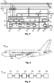
- Fig. 1 shows a schematic illustration of a power and data distribution (PADD) network 100.
- the PADD network 100 may generally be employed in an airborne vehicle such as an aircraft or spacecraft.
- Fig. 5 shows a schematic illustration of an exemplary aircraft 200 employing a PADD network, for example a PADD network 100 as shown and explained in conjunction with Figs. 1 to 4 .
- the PADD network 100 comprises one or more electrical power distribution centers (EPDCs) 50 that supply one or more power supply lines P with electrical power.
- the EPDCs 50 may comprise electrical power supply for a main network and/or electrical power supply for an emergency network as well as a ground power connector. In an airborne vehicle, two EPDCs 50 may be provided for the left hand and right hand generator sides.
- the EPDCs 50 ensure the reliable and high qualitative generation of electrical power, the segregation and management of the distribution of the generated electrical power as well as the controlling and monitoring of the electrical network.
- Fig. 2 exemplarily shows an EPDC 50 as may be employed in the PADD network 100 of Fig. 1 .
- the EPDC 50 may for example be an AC voltage EPDC 50 that comprises one or more electrical power supplies such as a variable frequency generator, a ram air turbine and/or an auxiliary generator.
- the electrical energy supplies generally denoted as 51, 52, and 53, may operate under different normal and emergency conditions and supply electrical power for different needs.
- the electrical energy supplies 51, 52 and 53 may further be connected in supply groups that supply a common power line.
- Each of the electrical energy supplies 51, 52 and 53 or groups of electrical energy supplies may be equipped with a switch to selectively deactivate the power supply from the respective electrical energy supply 51, 52 or 53.
- the power lines may be coupled to a plurality of electrical circuit breakers in the respective separate power lines which are configured to selectively decouple the plurality of electrical energy supplies 51, 52, 53 from the output of the EPDC 50.
- This control may be effected by an electrical network management controller (ENMF) 55 which is configured to control the plurality of electrical circuit breakers 54.
- ENMF electrical network management controller
- the EPDC 50 may in particular be a 115VAC power supply essential (ESS) operation, Extended Range Operations for Two-Engine Aeroplanes (ETOPS) operation, and emergency (EMER) condition cabin power (EEECP) cabin equipment which applies 115VAC output power over two times three single protected remote controlled circuit breaker power lines, one for each left hand and right hand system side of an airborne vehicle. Two different routes are provided to fulfil the particular risk requirements, such as engine burst, hydraulic accumulator burst and the like.
- the EEECP cabin equipment is configured to only switch the relevant power supply line, if all connected PADD modules 10 transmit the shedding status from all linked from the same system side under the relevant power supply condition.
- the ENMF 55 performs sheddings and reconfigures the PADD network 100 by configuration of the aircraft power demand and generation.
- the sheddings may in particular be dependent on the percentage of load on the remaining generators. For example, with one main generator in flight, the main AC bus bars of the opposite side will not be supplied and the ENMF 55 will shed loads based on power condition.
- the EPDC 50 may provide for 28 VDC power supply.
- four batteries may be connected to the 28 VDC power supply network to support no-break power transfer (NBPT) functionality in order to supply standby DC power and provide electrical power on ground.
- NBPT no-break power transfer
- Two out of four batteries may supply the emergency network with the charging and protection functionality being integrated in each of the batteries.
- the 28 VDC power supply may be provided on two normal power supply lines or power bus bars and on two emergency power supply lines or power bus bars.
- the DC power bus bars may normally be supplied from respective 230 VAC bus bars, with rectifiers/transformers transforming and distributing the 28 VDC DC power supply over the emergency power bus bars.
- one or more remote control circuit breaker units 56 may be connected in parallel which each comprise a remote control circuit breaker controller 58 (shedding information may be distributed via a data over power (DOP) from ENMF 55) coupled to a plurality of remote control circuit breakers 57.
- the system power operation will be controlled by the remote control circuit breaker controller 58 for all necessary electrical configurations.
- the remote control circuit breaker controller 58 manages the power supply for AC power loads usage by shedding and reconnecting the power supply lines selectively via the remote control circuit breakers 57, if enough power is available.
- the remote control circuit breaker controller 58 may monitor any cabin loads coupled downstream of the EPDC 50 and supplied with electrical power by the EPDC 50. Such cabin loads may include inter alia seat power supply systems, galleys, lavatory, commercial equipment fans, cabin air extraction fans, cabin lighting, ice protection control unit waste/water heating systems, floor panel heating systems and inflight entertainment systems.
- the physical architecture of the electrical distribution may consist of two distinct EPDCs 50 in a PADD network that may be located in the nose fuselage of the airborne vehicle.
- One of the EPDCs 50 may be a 28 VDC cabin power supply powered alternately under normal, essential and hot battery conditions.
- the other EPDC 50 may be a 115 VAC cabin power supply powered alternately under normal, essential, extended range operations for two-engine aeroplanes (ETOPS) and emergency conditions.
- EOPS two-engine aeroplanes
- Cabin equipment devices which shall apply a 28 VDC output power supply from the EPDC 50 acting as top line switching device are able to operate under essential and emergency conditions.
- the top line switching device may only be activated in emergency mode, as long as no command of the ENMF 55 overrides the control signals for the linked top line switching device.
- 28 VDC emergency functions may include passenger address, cabin interphone, emergency lighting, evacuation systems and smoke detection systems.
- the EPDC 50 acting as 115VAC power supply may supply power to operate essential and non-essential equipment under normal power supply conditions. In case of electrical essential condition, all non-essential loads will be shed, if the ENMF 55 sends an essential status configuration signal to the linked PADD modules 10. Similarly, the 115VAC power supply may supply power to operate some systems or equipment under ETOPS condition. In case of electrical ETOPS condition, all non-ETOPS loads will be shed, if the ENMF 55 sends an ETOPS status configuration signal to the linked PADD modules 10. Finally, the 115VAC power supply may supply power to operate some systems or equipment under emergency condition. In case of electrical emergency condition, all non-emergency loads will be shed, if the ENMF 55 sends an emergency status configuration signal to the linked PADD modules 10. Emergency functions for the cabin may inter alia include emergency lighting and oxygen containers.
- the PADD network 100 of Fig. 1 further includes a data communication director 60 that is coupled to the plurality of PADD modules 10 via a data bus D.
- the data bus D may be a high speed data bus, such as a CAN bus of Ethernet bus.
- the data bus D may be hardwired between the data communication director 60 to the respective PADD modules 10. Additionally, redundant data transmission may be effected via a wireless data communication system.
- the data bus D may be used for data communication with regard to bidirectional shedding information to be shared among the remote control circuit breaker controller 58, the ENMF 55 and communication units of the PADD modules 10.
- the wireless data communication may be used as full data backup in case of data corruption on the hardwired data bus D.
- data with regard to bidirectional shedding information may be distributed via a data over power (DOP) communication protocol.
- the bidirectional DOP information may include a healthy protocol, the shedding status of relevant shedding groups, for example detailed failure status, as well as the emergency status of major systems, for example the status of oxygen cabin decompression.
- DOP protocols By distributing shedding information via DOP protocols, the shedding information may be made available for decentralized shedding of loads within the PADD modules 10.
- Monitoring and command signals for shedding information may be transmitted bidirectionally and crossover bidirectionally from the ENMF 55 to the PADD modules 10 as well as 58 and vice versa.
- Fig. 3 shows an exemplary illustration of a PADD module 10 that may be employed in a PADD network of an airborne vehicle, such as the PADD network 100 of Fig. 1 .
- the PADD module 10 may comprise a plurality of first power supply interfaces 11, each configured to be connected to a plurality of power supply lines P1, P2 and P3.
- the power supply lines P1, P2 and P3 may for example be three phase power line of 115 VAC over which DOP shedding information may be distributed to the PADD module 10.
- the shedding information may for example be read out via a shedding transmission over power (STOP) interface of the PADD module 10.
- STOP shedding transmission over power
- the PADD module 10 may further comprise a data bus interface 12 configured to be connected to a data bus D1, particularly a high speed data bus D1.
- the PADD module 10 may be configured to supply electrical power from one of the first power supply interfaces 11 to electrical loads that are connected to a plurality of power output interfaces 26, 27, 28, 29 and 40 of the PADD module 10.
- a plurality of voltage distribution modules 19, 20 may be coupled between the plurality of first power supply interfaces 11 and the plurality of power output interfaces 26, 27, 28, 29 and 40.
- the distribution modules 19, 20 may be configured to provide AC or DC voltage by respective AC/DC or DC/DC converters.
- the PADD module 10 may further comprise a load shedding module 17 as central load controlling unit.
- the load shedding module 17 may for example be part of a primary power distribution module 16 within the PADD module 10.
- the load shedding module 17 may be configured to receive load shedding information via data communication over one or more of the plurality of power supply lines P1 to P3, specifically via the DOP communication protocol.
- a data concentrator 31 of the PADD module may be configured to receive redundant load shedding information via data communication over the data bus D.
- the redundant load shedding information may be shared with the load shedding module 17 within the PADD module.
- the data concentrator 31 may in particular be part of a data distribution module 30 of the PADD module 10.
- the load shedding module 17 is configured to shed one or more electrical loads connected to the plurality of power output interfaces 26 to 29 and 40 depending on the received load shedding information and the received redundant load shedding information.
- the PADD module 10 may comprise a wireless transceiver 32 which is coupled to the data concentrator 31.
- the data concentrator 31 may be configured to receive further redundant load shedding information via wireless data communication 33 over the wireless transceiver 32, to share with the load shedding module 17.
- the PADD module 10 comprises a secondary power supply interface 13 that is configured to be connected to EPDC 50 provide 28 VDC power supply (under normal, essential and hot battery conditions) or a PADD control unit.
- the secondary power supply interface 13 is secure via a solid state power controller 15 as part of a secondary power distribution module (SPDM) 14 coupled to the secondary power supply interface 13 that may be controlled by the load shedding module 17 depending on the various load shedding information.
- SPDM secondary power distribution module
- the PADD module 10 further comprises a plurality of circuit breaking devices 21, 22, 23, 24 and 39 that are coupled between respective ones of the power output interfaces 26 to 29 and 40 and the voltage distribution modules 19 and 20.
- a shedding control unit 18 under control of the load shedding module 17 may be configured to selectively activate or deactivate the circuit breaking devices 21 to 24 and 39 depending on the received load shedding information and the received redundant load shedding information.
- the basic functionality of the PADD module 10 is power Distribution (AC and DC), voltage transformation, shedding based on ENMF and STOP control signals and data communication via a linked high speed data bus and wireless data communication. Moreover, the PADD module 10 may provide power overload protection for the connected electrical loads.
- circuit breaking devices 21 to 24 and 39 such as RCCBs or SSPCs.
- Those protection devices are monitored and controlled in real-time in order to realize local and global safety criticality.
- the monitoring and controlling information is redundantly communicated via DOP communication protocol the high speed data bus as well as wireless data transmission, thereby enabling the system to recognize jamming attacks or disturbances of other transmitters reliably.
- the PADD module 10 may be implemented as an aircraft lavatory module, including fault current detection for shower use case functions in order to protect passengers and maintenance personnel from high voltages. This may be realized via a module internal grounding and bonding network.
- the PADD module 10 may also be implemented in a galley module of an aircraft, being equipped with additional fault current detection for bar use case functions, in order to protect passengers, cabin crew and maintenance personnel from high voltages. This may be realized via a module internal grounding and bonding network.
- Fig. 4 shows an illustration of an alternative implementation of a PADD module 10.
- the PADD module 10 of Fig. 4 may comprise a single data distribution module 30 which in turn includes a combined primary power and data distribution module 34 with a data concentrator 36 and a load shedding module 37.
- the PADD module 10 may be connected with an electrical energy storage device 38 that is connected to one of the power supply outputs 29 of the PADD module 10.
- the electrical energy storage device 38 may for example be a quantum super capacitor that may additionally and temporarily supply emergency lighting via the power supply output interface 29.
- Fig. 6 exemplarily illustrates a method M for power and data distribution in an airborne vehicle such as the airborne vehicle 200 of Fig. 5 , in particular using a PADD network 100 as illustrated in conjunction with Figs. 1 to 4 .
- the method M may comprise at M1 generating electrical power in at least one electrical power distribution center 50.
- the generated electrical power may be distributed via one or more power supply lines to a plurality of PADD modules 10, which receive, at M3, load shedding information via data communication over one or more of the plurality of power supply lines.
- redundant load shedding information may be received at the plurality of PADD modules 10 via data communication over a data bus.
- the redundant load shedding information may be transmitted in the plurality of PADD modules 10 to a load shedding module in the PADD modules 10 at M5. These load shedding modules may then, at M6, and shed one or more electrical loads connected to power output interfaces of the PADD modules 10 depending on the received load shedding information and the received redundant load shedding information.
Claims (12)
- Leistungs- und Datenverteilungsmodul, PADD-Modul, (10), das Folgendes umfasst:mehrere erste Leistungsversorgungsschnittstellen (11), die jeweils konfiguriert sind, mit mehreren Leistungsversorgungsleitungen (P; P1; P2; P3) verbunden zu sein;eine Datenbusschnittstelle (12), die konfiguriert ist, mit einem Datenbus (D; D1) verbunden zu sein;mehrere Leistungsausgabeschnittstellen (26; 27; 28; 29; 40), die jeweils konfiguriert sind, mit einer oder mehreren elektrischen Lasten verbunden zu sein und von einer der ersten Leistungsversorgungsschnittstellen (11) elektrische Leistung den angeschlossenen elektrischen Lasten zuzuführen;mehrere Spannungsverteilungsmodule (19; 20), die zwischen die mehreren ersten Leistungsversorgungsschnittstellen (11) und die mehreren Leistungsausgabeschnittstellen (26; 27; 28; 29; 40) gekoppelt sind und konfiguriert sind, über die Leistungsausgabeschnittstellen (26; 27; 28; 29; 40) eine Wechsel- oder Gleichspannung bereitzustellen;ein Lastabstoßungsmodul (17; 37), das konfiguriert ist, Lastabstoßungsinformationen zu empfangen; undeinen Datenkonzentrator (31; 36), der konfiguriert ist, redundante Lastabstoßungsinformationen über eine Datenkommunikation über den Datenbus (D; D1) zu empfangen und die redundanten Lastabstoßungsinformationen zu dem Lastabstoßungsmodul (17; 37) zu übertragen,wobei das Lastabstoßungsmodul (17; 37) ferner konfiguriert ist, eine oder mehrere elektrische Lasten, die mit den mehreren Leistungsausgabeschnittstellen (26; 27; 28; 29; 40) verbunden sind, abhängig von den empfangenen Lastabstoßungsinformationen und den empfangenen redundanten Lastabstoßungsinformationen abzustoßen;dadurch gekennzeichnet, dass das PADD-Modul (10) ferner Folgendes umfasst:eine sekundäre Leistungsversorgungsschnittstelle (13), die konfiguriert ist, mit anderen PADD-Modulen (10) verbunden zu sein; undeinen Festkörper-Leistungs-Controller (15), der an die sekundäre Leistungsversorgungsschnittstelle (13) gekoppelt ist,wobei das Lastabstoßungsmodul (17; 37) ferner konfiguriert ist, den Festkörper-Leistungs-Controller (15) abhängig von den empfangenen Lastabstoßungsinformationen und den empfangenen redundanten Lastabstoßungsinformationen zu steuern; undwobei das Lastabstoßungsmodul (17; 37) konfiguriert ist, die Lastabstoßungsinformationen über eine Datenkommunikation über eine oder mehrere der mehreren Leistungsversorgungsleitungen (P; P1; P2; P3) zu empfangen.
- PADD-Modul (10) nach Anspruch 1, das ferner Folgendes umfasst:einen drahtlosen Sender/Empfänger (32), der an den Datenkonzentrator (31; 36) gekoppelt ist,wobei der Datenkonzentrator (31; 36) konfiguriert ist, die redundanten Lastabstoßungsinformationen über eine drahtlose Datenkommunikation (33) über den drahtlosen Sender/Empfänger (32) zu empfangen.
- PADD-Modul (10) nach einem der Ansprüche 1 oder 2, das ferner Folgendes umfasst:mehrere Schaltungsunterbrechungsvorrichtungen (21; 22; 23; 24; 39), die zwischen die Leistungsausgabeschnittstellen (26; 27; 28; 29; 40) und die Spannungsverteilungsmodule (19; 20) geschaltet sind; undeine Abstoßungssteuereinheit (18), die an das Lastabstoßungsmodul (17) gekoppelt ist, wobei die Abstoßungssteuereinheit (18) konfiguriert ist, die Schaltungsunterbrechungsvorrichtungen (21; 22; 23; 24; 39) abhängig von den empfangenen Lastabstoßungsinformationen und den empfangenen redundanten Lastabstoßungsinformationen selektiv zu aktivieren oder zu deaktivieren.
- PADD-Modul (10) nach einem der Ansprüche 1 bis 3, wobei die sekundäre Leistungsversorgungsschnittstelle (13) konfiguriert ist, die Gleichstromleistung einer heißen Batterie zu empfangen.
- PADD-Modul (10) nach einem der Ansprüche 1 bis 4, wobei die Datenbusschnittstelle (12) konfiguriert ist, Hochgeschwindigkeitskabinendaten zu empfangen.
- PADD-Modul (10) nach einem der Ansprüche 1 bis 5, das ferner Folgendes umfasst:
eine Speichervorrichtung (38) für elektrische Energie, die an wenigstens eine der mehreren Leistungsausgabeschnittstellen (29) gekoppelt ist und konfiguriert ist, elektrische Energie vorübergehend zu speichern, um sie für eine oder mehrere elektrische Lasten bereitzustellen, die an die wenigstens eine der mehreren Leistungsausgabeschnittstellen (29) gekoppelt sind. - PADD-Modul (10) nach einem der Ansprüche 1 bis 6, wobei das PADD-Modul (10) ein Luftfahrzeug-Bordküchenmodul oder ein Luftfahrzeug-Toilettenmodul ist.
- Leistungs- und Datenverteilungsnetz, PADD-Netz, (100), das Folgendes umfasst:mehrere PADD-Module (10) nach einem der Ansprüche 1 bis 7;wenigstens ein Verteilungszentrum (50) für elektrische Leistung, das über eine oder mehrere der ersten Leistungsversorgungsschnittstellen (11) an die mehreren PADD-Module (10) gekoppelt ist; undeine Datenkommunikations-Leitvorrichtung (60), die über die Datenbusschnittstelle (12) an die mehreren PADD-Module (10) gekoppelt ist.
- PADD-Netz (10) nach Anspruch 8, wobei das wenigstens eine Verteilungszentrum (50) für elektrische Leistung Folgendes umfasst:mehrere Zufuhrvorrichtungen (51; 52; 53) für elektrische Energie; undmehrere Schaltungsunterbrechungsvorrichtungen (54), die an die mehreren Zufuhrvorrichtungen (51; 52; 53) für elektrische Energie gekoppelt sind und die konfiguriert sind, die mehreren Zufuhrvorrichtungen (51; 52; 53) für elektrische Energie von dem Ausgang des Verteilungszentrums (50) für elektrische Leistung selektiv zu entkoppeln.
- PADD-Netz (100) nach Anspruch 9, das ferner Folgendes umfasst:
einen Management-Controller (55) des elektrischen Netzes, der konfiguriert ist, die mehreren Schaltungsunterbrechungsvorrichtungen (54) zu steuern. - Luftfahrzeug (200), das ein PADD-Netz (100) nach einem der Ansprüche 8 bis 10 umfasst.
- Verfahren (M) zur Leistungs- und Datenverteilung, PADD, in einem Luftfahrzeug (200), wobei das Verfahren (M) Folgendes umfasst:Erzeugen (M1) elektrischer Leistung in wenigstens einem Verteilungszentrum (50) für elektrische Leistung;Verteilen (M2) der erzeugten elektrischen Leistung über eine oder mehrere Leistungsversorgungsleitungen (P; P1; P2; P3) zu mehreren PADD-Modulen (10);Empfangen (M3) von Lastabstoßungsinformationen an den mehreren PADD-Modulen (10);Empfangen (M4) redundanter Lastabstoßungsinformationen über eine Datenkommunikation über einen Datenbus (D; D1) an den mehreren PADD-Modulen (10);Übertragen (M5) der redundanten Lastabstoßungsinformationen in den mehreren PADD-Modulen (10) zu einem Lastabstoßungsmodul (17; 37) der PADD-Module (10); undAbstoßen (M6) einer oder mehrerer elektrischer Lasten, die mit den Leistungsausgabeschnittstellen (26; 27; 28; 29; 40) der PADD-Module (10) verbunden sind, abhängig von den empfangenen Lastabstoßungsinformationen und den empfangenen redundanten Lastabstoßungsinformationen,wobei das Verfahren durch die folgenden Schritte gekennzeichnet istSteuern eines Festkörper-Leistungs-Controllers (15) abhängig von den empfangenen Lastabstoßungsinformationen und den empfangenen redundanten Lastabstoßungsinformationen,wobei der Festkörper-Leistungs-Controller (15) an eine sekundäre Leistungsversorgungsschnittstelle (13) gekoppelt ist, wobei die sekundäre Leistungsversorgungsschnittstelle (13) konfiguriert ist, mit anderen PADD-Modulen (10) verbunden zu sein, undwobei die Lastabstoßungsinformationen an den mehreren PADD-Modulen (10) über eine Datenkommunikation über eine oder mehrere der mehreren Leistungsversorgungsleitungen (P; P1; P2; P3) empfangen werden.
Priority Applications (3)
| Application Number | Priority Date | Filing Date | Title |
|---|---|---|---|
| EP14168455.5A EP2945244B1 (de) | 2014-05-15 | 2014-05-15 | Leistungs- und Datenverteilungsmodul und Verfahren zur Leistungs- und Datenverteilung in einem Flugkörper |
| PCT/EP2014/075920 WO2015172857A1 (en) | 2014-05-15 | 2014-11-28 | Power and data distribution module and method for power and data distribution in an airborne vehicle |
| US15/347,201 US11018521B2 (en) | 2014-05-15 | 2016-11-09 | Power and data distribution module and method for power and data distribution in an airborne vehicle |
Applications Claiming Priority (1)
| Application Number | Priority Date | Filing Date | Title |
|---|---|---|---|
| EP14168455.5A EP2945244B1 (de) | 2014-05-15 | 2014-05-15 | Leistungs- und Datenverteilungsmodul und Verfahren zur Leistungs- und Datenverteilung in einem Flugkörper |
Publications (2)
| Publication Number | Publication Date |
|---|---|
| EP2945244A1 EP2945244A1 (de) | 2015-11-18 |
| EP2945244B1 true EP2945244B1 (de) | 2022-07-06 |
Family
ID=50732821
Family Applications (1)
| Application Number | Title | Priority Date | Filing Date |
|---|---|---|---|
| EP14168455.5A Active EP2945244B1 (de) | 2014-05-15 | 2014-05-15 | Leistungs- und Datenverteilungsmodul und Verfahren zur Leistungs- und Datenverteilung in einem Flugkörper |
Country Status (3)
| Country | Link |
|---|---|
| US (1) | US11018521B2 (de) |
| EP (1) | EP2945244B1 (de) |
| WO (1) | WO2015172857A1 (de) |
Families Citing this family (30)
| Publication number | Priority date | Publication date | Assignee | Title |
|---|---|---|---|---|
| FR3004701B1 (fr) * | 2013-04-22 | 2015-04-03 | Snecma | Dispositif de delestage des alternateurs d'un turboreacteur pendant ses accelerations |
| FR3038274B1 (fr) | 2015-07-01 | 2020-10-23 | Airbus Operations Sas | Systeme de raccordement electrique d'un equipement de cabine d'un avion a un systeme de controle et a au moins une source d'alimentation electrique dudit avion |
| US10202088B2 (en) | 2016-01-15 | 2019-02-12 | Hamilton Sundstrand Corporation | Combined remote sensing, processing, and solid state power control system |
| GB2550381B (en) * | 2016-05-18 | 2020-06-24 | Ge Aviat Systems Ltd | An electric distribution architecture |
| US10362035B1 (en) * | 2016-07-22 | 2019-07-23 | Rockwell Collins, Inc. | Secured communications using avionics power bus network |
| EP3287990B1 (de) * | 2016-08-25 | 2020-09-30 | Airbus Operations GmbH | Datenerfassungssystem und verfahren zur datenerfassung |
| WO2018065043A1 (en) * | 2016-10-05 | 2018-04-12 | Jmp Ingenieros S.L. | Modular power bus architecture and method for optimum power management of distributed power sources and drains |
| DE102016226148A1 (de) * | 2016-12-23 | 2018-06-28 | Siemens Aktiengesellschaft | Elektrische Vorrichtung für ein Schienenfahrzeug |
| US10071698B2 (en) | 2017-02-16 | 2018-09-11 | Motor Coach Industries Limited | Power distribution module for use in a vehicle |
| USD863227S1 (en) | 2017-02-16 | 2019-10-15 | Motor Coach Industries Limited | Main distribution panel |
| DE102017205535B4 (de) | 2017-03-31 | 2024-03-07 | Airbus Operations Gmbh | Schnittstellenarchitektur, Kabinenmonument und Verfahren zur Anbindung eines Kabinenmonuments in einem Flugzeug |
| US10942527B2 (en) * | 2017-05-30 | 2021-03-09 | Textron Innovations Inc. | System and method for controlling rotorcraft load priority |
| FR3068182B1 (fr) * | 2017-06-22 | 2020-11-06 | Airbus Helicopters | Boitier de distribution electrique integrant les fonctions de disjonctions, de delestage et de conversion pour aeronef |
| US10848341B2 (en) * | 2017-08-02 | 2020-11-24 | Airbus Operations Sas | Aircraft comprising a hybrid electrical power distribution and data communication network |
| EP3439244B1 (de) * | 2017-08-02 | 2019-09-18 | Airbus Operations S.A.S. | Modulares element für ein gemischtes luftfahrzeugnetzwerk |
| US10764753B2 (en) | 2017-09-27 | 2020-09-01 | The Boeing Company | Flight crew connectivity systems and methods |
| US11412374B2 (en) | 2017-09-27 | 2022-08-09 | The Boeing Company | Aircraft interface device |
| FR3073099B1 (fr) * | 2017-10-30 | 2019-10-11 | Airbus Helicopters | Boitier de distribution electrique et de concentration de donnees pour aeronef. |
| US11139992B1 (en) * | 2017-10-30 | 2021-10-05 | Rockwell Collins, Inc. | Systems and methods for remotely powered data concentrators for distributed IMA system |
| CN108011443B (zh) * | 2017-12-01 | 2021-02-26 | 中国直升机设计研究所 | 一种直升机非应急负载卸载系统及其卸载方法 |
| DE102018204060A1 (de) * | 2018-03-16 | 2019-09-19 | Rp-Technik Gmbh | Verteiltes Messsystem und Verfahren zu dessen Steuerung, insbesondere zur Überwachung eines Akkumulator-Arrays |
| FR3085559B1 (fr) * | 2018-09-05 | 2021-04-16 | Eric Borderes | Installation electrique a redeploiement rapide |
| CN111293864A (zh) * | 2018-12-07 | 2020-06-16 | 上海航空电器有限公司 | 集成多种电源转换功能的远程配电装置架构 |
| CN111064198A (zh) * | 2019-12-31 | 2020-04-24 | 南京因泰莱电器股份有限公司 | 多回路供电配电网的快速负荷调控方法 |
| DE102020206023A1 (de) * | 2020-05-13 | 2021-11-18 | Kid-Systeme Gmbh | Elektrisches leistungsverteilungssystem und allokationsverfahren zur verteilung von elektrischer leistung |
| CN111769542A (zh) * | 2020-08-03 | 2020-10-13 | 中国能源建设集团湖南省电力设计院有限公司 | 一种220kV智慧能源站站用直流电源系统 |
| FR3114196B1 (fr) | 2020-09-15 | 2022-08-05 | Airbus Helicopters | procédé et véhicule muni d’un système de délestage comprenant au moins un détecteur de fumée |
| CN113867446B (zh) * | 2021-10-21 | 2022-04-26 | 北京微纳星空科技有限公司 | 一种微纳卫星的控制系统及微纳卫星 |
| US11929617B2 (en) | 2021-10-28 | 2024-03-12 | Lockheed Martin Corporation | Dynamic electrical load control |
| US20230253801A1 (en) * | 2022-02-10 | 2023-08-10 | Lockheed Martin Corporation | Power-data nodes for an aircraft system |
Family Cites Families (25)
| Publication number | Priority date | Publication date | Assignee | Title |
|---|---|---|---|---|
| DE19617915C2 (de) | 1996-05-03 | 2001-11-08 | Eads Airbus Gmbh | Anordnung zur Energieverteilung, in einem Flugzeug |
| US6249913B1 (en) * | 1998-10-09 | 2001-06-19 | General Dynamics Ots (Aerospace), Inc. | Aircraft data management system |
| US6664656B2 (en) | 2000-09-14 | 2003-12-16 | The Boeing Company | Aircraft electrical power distribution network |
| US7020790B2 (en) * | 2001-02-08 | 2006-03-28 | Honeywell International Inc. | Electric load management center including gateway module and multiple load management modules for distributing power to multiple loads |
| US7136725B1 (en) * | 2001-06-21 | 2006-11-14 | Paciorek Ronald R | Load shed notification method, product, and apparatus |
| US8005580B2 (en) * | 2003-12-09 | 2011-08-23 | The Boeing Company | Aircraft galley systems and methods for managing electric power for aircraft galley systems |
| US7505400B2 (en) * | 2004-09-22 | 2009-03-17 | Honeywell International Inc. | Dual lane connection to dual redundant avionics networks |
| US8704678B2 (en) * | 2005-03-08 | 2014-04-22 | Jackson Kit Wang | Systems and methods for modifying utility usage |
| FR2900637B1 (fr) | 2006-05-04 | 2009-02-13 | Airbus France Sas | Dispositif et procede pour gerer l'activation ou la desactivation des alimentations electriques des systemes electriques a bord d'un aeronef |
| US7634329B2 (en) * | 2007-03-05 | 2009-12-15 | Honeywell International Inc. | Intelligent aircraft secondary power distribution system that facilitates condition based maintenance |
| US7598625B2 (en) * | 2007-06-08 | 2009-10-06 | Honeywell International Inc. | Network-based aircraft secondary electric power distribution system |
| US7921315B2 (en) * | 2008-05-09 | 2011-04-05 | International Business Machines Corporation | Managing power consumption in a data center based on monitoring circuit breakers |
| US8022711B2 (en) * | 2008-12-17 | 2011-09-20 | Hamilton Sundstrand Corporation | Wire fault locating in distributed power systems |
| US8135499B2 (en) * | 2009-07-07 | 2012-03-13 | International Business Machines Corporation | Load shedding of a selected substation by an electric utility |
| US8390151B2 (en) * | 2010-03-10 | 2013-03-05 | Hamilton Sundstrand Corporation | SSPC with active current limiting |
| GB201015760D0 (en) | 2010-09-21 | 2010-10-27 | Airbus Uk Ltd | Aircraft power distribution network |
| US8880235B2 (en) * | 2011-11-15 | 2014-11-04 | Palo Alto Research Center Incorporated | Staggering and feathering of demand response and energy supply change in a managed electrical system |
| DE102011088068B3 (de) * | 2011-12-09 | 2013-04-18 | Airbus Operations Gmbh | Schnittstelleneinrichtung für Kabinenmonumente |
| US8704574B2 (en) * | 2012-02-13 | 2014-04-22 | Honeywell International Inc. | SSPC distribution system and control strategy |
| US9172272B2 (en) * | 2012-02-17 | 2015-10-27 | Sikorsky Aircraft Corporation | Electrical power distribution system |
| CA3114227C (en) * | 2012-07-12 | 2023-09-19 | Pratt & Whitney Canada Corp. | Aircraft power outtake management |
| JP6170370B2 (ja) * | 2013-08-07 | 2017-07-26 | 三菱航空機株式会社 | 航空機におけるロードシェッド方法および制御装置 |
| US9944400B2 (en) * | 2014-02-11 | 2018-04-17 | Sikorsky Aircraft Corporation | Adaptive engine acceleration for accessory loads |
| US20150311815A1 (en) * | 2014-04-25 | 2015-10-29 | Parker-Hannifin Corporation | Hermetic high current solid state power controller |
| US20160306417A1 (en) * | 2015-04-13 | 2016-10-20 | Phitek Systems Limited | Power management system |
-
2014
- 2014-05-15 EP EP14168455.5A patent/EP2945244B1/de active Active
- 2014-11-28 WO PCT/EP2014/075920 patent/WO2015172857A1/en active Application Filing
-
2016
- 2016-11-09 US US15/347,201 patent/US11018521B2/en active Active
Also Published As
| Publication number | Publication date |
|---|---|
| US20170063151A1 (en) | 2017-03-02 |
| US11018521B2 (en) | 2021-05-25 |
| EP2945244A1 (de) | 2015-11-18 |
| WO2015172857A1 (en) | 2015-11-19 |
Similar Documents
| Publication | Publication Date | Title |
|---|---|---|
| US11018521B2 (en) | Power and data distribution module and method for power and data distribution in an airborne vehicle | |
| EP2442425B1 (de) | Elektrisches Leistungssteuerungssystem für ein Fahrzeug | |
| US10493930B2 (en) | Modular equipment center solid state primary power switching network | |
| EP3055917B1 (de) | Verteilte unabhängige schutzvorrichtungen für modulares equipement-center | |
| US7800245B2 (en) | Method and architecture for reduction in vehicle wiring | |
| US9561867B2 (en) | Modular equipment center lightning threat reduction architecture | |
| US9676351B2 (en) | Modular equipment center solid state primary power switching network | |
| EP2408085B1 (de) | Verfahren für die Flugzeug-Notstromversorgung | |
| CN102037626B (zh) | 用于管理电气网络的方法 | |
| US9511728B2 (en) | Modular equipment center distributed primary power architecture | |
| US9771154B2 (en) | Seat power systems and methods | |
| US9964044B2 (en) | Auxiliary power unit starting system for an aircraft | |
| CN109417293B (zh) | 配电架构 | |
| JP2014516324A (ja) | 輸送手段の電力管理および配電 | |
| JP7220662B2 (ja) | 航空機において機内電力を分配するための方法及びアーキテクチャ | |
| US9561761B2 (en) | Modular equipment center zonal standalone power system control architecture | |
| EP2852020B1 (de) | Energieverteilungsarchitektur und Flugzeug mit der Energieverteilungsarchitektur | |
| US20160211673A1 (en) | Localized source selection and power conversion power distribution system | |
| CN108189784A (zh) | 履带装甲车辆环形配电系统 |
Legal Events
| Date | Code | Title | Description |
|---|---|---|---|
| PUAI | Public reference made under article 153(3) epc to a published international application that has entered the european phase |
Free format text: ORIGINAL CODE: 0009012 |
|
| AK | Designated contracting states |
Kind code of ref document: A1 Designated state(s): AL AT BE BG CH CY CZ DE DK EE ES FI FR GB GR HR HU IE IS IT LI LT LU LV MC MK MT NL NO PL PT RO RS SE SI SK SM TR |
|
| AX | Request for extension of the european patent |
Extension state: BA ME |
|
| STAA | Information on the status of an ep patent application or granted ep patent |
Free format text: STATUS: REQUEST FOR EXAMINATION WAS MADE |
|
| 17P | Request for examination filed |
Effective date: 20160503 |
|
| RBV | Designated contracting states (corrected) |
Designated state(s): AL AT BE BG CH CY CZ DE DK EE ES FI FR GB GR HR HU IE IS IT LI LT LU LV MC MK MT NL NO PL PT RO RS SE SI SK SM TR |
|
| STAA | Information on the status of an ep patent application or granted ep patent |
Free format text: STATUS: EXAMINATION IS IN PROGRESS |
|
| 17Q | First examination report despatched |
Effective date: 20210311 |
|
| STAA | Information on the status of an ep patent application or granted ep patent |
Free format text: STATUS: EXAMINATION IS IN PROGRESS |
|
| GRAP | Despatch of communication of intention to grant a patent |
Free format text: ORIGINAL CODE: EPIDOSNIGR1 |
|
| STAA | Information on the status of an ep patent application or granted ep patent |
Free format text: STATUS: GRANT OF PATENT IS INTENDED |
|
| INTG | Intention to grant announced |
Effective date: 20220211 |
|
| GRAS | Grant fee paid |
Free format text: ORIGINAL CODE: EPIDOSNIGR3 |
|
| GRAA | (expected) grant |
Free format text: ORIGINAL CODE: 0009210 |
|
| STAA | Information on the status of an ep patent application or granted ep patent |
Free format text: STATUS: THE PATENT HAS BEEN GRANTED |
|
| AK | Designated contracting states |
Kind code of ref document: B1 Designated state(s): AL AT BE BG CH CY CZ DE DK EE ES FI FR GB GR HR HU IE IS IT LI LT LU LV MC MK MT NL NO PL PT RO RS SE SI SK SM TR |
|
| REG | Reference to a national code |
Ref country code: GB Ref legal event code: FG4D |
|
| REG | Reference to a national code |
Ref country code: AT Ref legal event code: REF Ref document number: 1503567 Country of ref document: AT Kind code of ref document: T Effective date: 20220715 Ref country code: CH Ref legal event code: EP |
|
| REG | Reference to a national code |
Ref country code: DE Ref legal event code: R096 Ref document number: 602014084207 Country of ref document: DE |
|
| REG | Reference to a national code |
Ref country code: IE Ref legal event code: FG4D |
|
| REG | Reference to a national code |
Ref country code: LT Ref legal event code: MG9D |
|
| REG | Reference to a national code |
Ref country code: NL Ref legal event code: MP Effective date: 20220706 |
|
| PG25 | Lapsed in a contracting state [announced via postgrant information from national office to epo] |
Ref country code: SE Free format text: LAPSE BECAUSE OF FAILURE TO SUBMIT A TRANSLATION OF THE DESCRIPTION OR TO PAY THE FEE WITHIN THE PRESCRIBED TIME-LIMIT Effective date: 20220706 Ref country code: RS Free format text: LAPSE BECAUSE OF FAILURE TO SUBMIT A TRANSLATION OF THE DESCRIPTION OR TO PAY THE FEE WITHIN THE PRESCRIBED TIME-LIMIT Effective date: 20220706 Ref country code: PT Free format text: LAPSE BECAUSE OF FAILURE TO SUBMIT A TRANSLATION OF THE DESCRIPTION OR TO PAY THE FEE WITHIN THE PRESCRIBED TIME-LIMIT Effective date: 20221107 Ref country code: NO Free format text: LAPSE BECAUSE OF FAILURE TO SUBMIT A TRANSLATION OF THE DESCRIPTION OR TO PAY THE FEE WITHIN THE PRESCRIBED TIME-LIMIT Effective date: 20221006 Ref country code: NL Free format text: LAPSE BECAUSE OF FAILURE TO SUBMIT A TRANSLATION OF THE DESCRIPTION OR TO PAY THE FEE WITHIN THE PRESCRIBED TIME-LIMIT Effective date: 20220706 Ref country code: LV Free format text: LAPSE BECAUSE OF FAILURE TO SUBMIT A TRANSLATION OF THE DESCRIPTION OR TO PAY THE FEE WITHIN THE PRESCRIBED TIME-LIMIT Effective date: 20220706 Ref country code: LT Free format text: LAPSE BECAUSE OF FAILURE TO SUBMIT A TRANSLATION OF THE DESCRIPTION OR TO PAY THE FEE WITHIN THE PRESCRIBED TIME-LIMIT Effective date: 20220706 Ref country code: FI Free format text: LAPSE BECAUSE OF FAILURE TO SUBMIT A TRANSLATION OF THE DESCRIPTION OR TO PAY THE FEE WITHIN THE PRESCRIBED TIME-LIMIT Effective date: 20220706 Ref country code: ES Free format text: LAPSE BECAUSE OF FAILURE TO SUBMIT A TRANSLATION OF THE DESCRIPTION OR TO PAY THE FEE WITHIN THE PRESCRIBED TIME-LIMIT Effective date: 20220706 |
|
| REG | Reference to a national code |
Ref country code: AT Ref legal event code: MK05 Ref document number: 1503567 Country of ref document: AT Kind code of ref document: T Effective date: 20220706 |
|
| PG25 | Lapsed in a contracting state [announced via postgrant information from national office to epo] |
Ref country code: PL Free format text: LAPSE BECAUSE OF FAILURE TO SUBMIT A TRANSLATION OF THE DESCRIPTION OR TO PAY THE FEE WITHIN THE PRESCRIBED TIME-LIMIT Effective date: 20220706 Ref country code: IS Free format text: LAPSE BECAUSE OF FAILURE TO SUBMIT A TRANSLATION OF THE DESCRIPTION OR TO PAY THE FEE WITHIN THE PRESCRIBED TIME-LIMIT Effective date: 20221106 Ref country code: HR Free format text: LAPSE BECAUSE OF FAILURE TO SUBMIT A TRANSLATION OF THE DESCRIPTION OR TO PAY THE FEE WITHIN THE PRESCRIBED TIME-LIMIT Effective date: 20220706 Ref country code: GR Free format text: LAPSE BECAUSE OF FAILURE TO SUBMIT A TRANSLATION OF THE DESCRIPTION OR TO PAY THE FEE WITHIN THE PRESCRIBED TIME-LIMIT Effective date: 20221007 |
|
| REG | Reference to a national code |
Ref country code: DE Ref legal event code: R097 Ref document number: 602014084207 Country of ref document: DE |
|
| PG25 | Lapsed in a contracting state [announced via postgrant information from national office to epo] |
Ref country code: SM Free format text: LAPSE BECAUSE OF FAILURE TO SUBMIT A TRANSLATION OF THE DESCRIPTION OR TO PAY THE FEE WITHIN THE PRESCRIBED TIME-LIMIT Effective date: 20220706 Ref country code: RO Free format text: LAPSE BECAUSE OF FAILURE TO SUBMIT A TRANSLATION OF THE DESCRIPTION OR TO PAY THE FEE WITHIN THE PRESCRIBED TIME-LIMIT Effective date: 20220706 Ref country code: DK Free format text: LAPSE BECAUSE OF FAILURE TO SUBMIT A TRANSLATION OF THE DESCRIPTION OR TO PAY THE FEE WITHIN THE PRESCRIBED TIME-LIMIT Effective date: 20220706 Ref country code: CZ Free format text: LAPSE BECAUSE OF FAILURE TO SUBMIT A TRANSLATION OF THE DESCRIPTION OR TO PAY THE FEE WITHIN THE PRESCRIBED TIME-LIMIT Effective date: 20220706 Ref country code: AT Free format text: LAPSE BECAUSE OF FAILURE TO SUBMIT A TRANSLATION OF THE DESCRIPTION OR TO PAY THE FEE WITHIN THE PRESCRIBED TIME-LIMIT Effective date: 20220706 |
|
| PLBE | No opposition filed within time limit |
Free format text: ORIGINAL CODE: 0009261 |
|
| STAA | Information on the status of an ep patent application or granted ep patent |
Free format text: STATUS: NO OPPOSITION FILED WITHIN TIME LIMIT |
|
| PG25 | Lapsed in a contracting state [announced via postgrant information from national office to epo] |
Ref country code: SK Free format text: LAPSE BECAUSE OF FAILURE TO SUBMIT A TRANSLATION OF THE DESCRIPTION OR TO PAY THE FEE WITHIN THE PRESCRIBED TIME-LIMIT Effective date: 20220706 Ref country code: EE Free format text: LAPSE BECAUSE OF FAILURE TO SUBMIT A TRANSLATION OF THE DESCRIPTION OR TO PAY THE FEE WITHIN THE PRESCRIBED TIME-LIMIT Effective date: 20220706 |
|
| 26N | No opposition filed |
Effective date: 20230411 |
|
| PG25 | Lapsed in a contracting state [announced via postgrant information from national office to epo] |
Ref country code: AL Free format text: LAPSE BECAUSE OF FAILURE TO SUBMIT A TRANSLATION OF THE DESCRIPTION OR TO PAY THE FEE WITHIN THE PRESCRIBED TIME-LIMIT Effective date: 20220706 |
|
| PGFP | Annual fee paid to national office [announced via postgrant information from national office to epo] |
Ref country code: FR Payment date: 20230526 Year of fee payment: 10 Ref country code: DE Payment date: 20230519 Year of fee payment: 10 |
|
| PG25 | Lapsed in a contracting state [announced via postgrant information from national office to epo] |
Ref country code: SI Free format text: LAPSE BECAUSE OF FAILURE TO SUBMIT A TRANSLATION OF THE DESCRIPTION OR TO PAY THE FEE WITHIN THE PRESCRIBED TIME-LIMIT Effective date: 20220706 |
|
| PGFP | Annual fee paid to national office [announced via postgrant information from national office to epo] |
Ref country code: GB Payment date: 20230524 Year of fee payment: 10 |
|
| REG | Reference to a national code |
Ref country code: CH Ref legal event code: PL |
|
| PG25 | Lapsed in a contracting state [announced via postgrant information from national office to epo] |
Ref country code: MC Free format text: LAPSE BECAUSE OF FAILURE TO SUBMIT A TRANSLATION OF THE DESCRIPTION OR TO PAY THE FEE WITHIN THE PRESCRIBED TIME-LIMIT Effective date: 20220706 |
|
| REG | Reference to a national code |
Ref country code: BE Ref legal event code: MM Effective date: 20230531 |
|
| PG25 | Lapsed in a contracting state [announced via postgrant information from national office to epo] |
Ref country code: MC Free format text: LAPSE BECAUSE OF FAILURE TO SUBMIT A TRANSLATION OF THE DESCRIPTION OR TO PAY THE FEE WITHIN THE PRESCRIBED TIME-LIMIT Effective date: 20220706 Ref country code: LU Free format text: LAPSE BECAUSE OF NON-PAYMENT OF DUE FEES Effective date: 20230515 Ref country code: LI Free format text: LAPSE BECAUSE OF NON-PAYMENT OF DUE FEES Effective date: 20230531 Ref country code: IT Free format text: LAPSE BECAUSE OF FAILURE TO SUBMIT A TRANSLATION OF THE DESCRIPTION OR TO PAY THE FEE WITHIN THE PRESCRIBED TIME-LIMIT Effective date: 20220706 Ref country code: CH Free format text: LAPSE BECAUSE OF NON-PAYMENT OF DUE FEES Effective date: 20230531 |
|
| REG | Reference to a national code |
Ref country code: IE Ref legal event code: MM4A |
|
| PG25 | Lapsed in a contracting state [announced via postgrant information from national office to epo] |
Ref country code: IE Free format text: LAPSE BECAUSE OF NON-PAYMENT OF DUE FEES Effective date: 20230515 |