EP2945221A1 - Three-axis antenna - Google Patents
Three-axis antenna Download PDFInfo
- Publication number
- EP2945221A1 EP2945221A1 EP15167093.2A EP15167093A EP2945221A1 EP 2945221 A1 EP2945221 A1 EP 2945221A1 EP 15167093 A EP15167093 A EP 15167093A EP 2945221 A1 EP2945221 A1 EP 2945221A1
- Authority
- EP
- European Patent Office
- Prior art keywords
- antenna
- axis
- coils
- sheet
- core
- Prior art date
- Legal status (The legal status is an assumption and is not a legal conclusion. Google has not performed a legal analysis and makes no representation as to the accuracy of the status listed.)
- Withdrawn
Links
Images






Classifications
-
- H—ELECTRICITY
- H01—ELECTRIC ELEMENTS
- H01Q—ANTENNAS, i.e. RADIO AERIALS
- H01Q7/00—Loop antennas with a substantially uniform current distribution around the loop and having a directional radiation pattern in a plane perpendicular to the plane of the loop
-
- H—ELECTRICITY
- H01—ELECTRIC ELEMENTS
- H01Q—ANTENNAS, i.e. RADIO AERIALS
- H01Q1/00—Details of, or arrangements associated with, antennas
- H01Q1/27—Adaptation for use in or on movable bodies
- H01Q1/32—Adaptation for use in or on road or rail vehicles
- H01Q1/3208—Adaptation for use in or on road or rail vehicles characterised by the application wherein the antenna is used
- H01Q1/3233—Adaptation for use in or on road or rail vehicles characterised by the application wherein the antenna is used particular used as part of a sensor or in a security system, e.g. for automotive radar, navigation systems
- H01Q1/3241—Adaptation for use in or on road or rail vehicles characterised by the application wherein the antenna is used particular used as part of a sensor or in a security system, e.g. for automotive radar, navigation systems particular used in keyless entry systems
-
- H—ELECTRICITY
- H01—ELECTRIC ELEMENTS
- H01Q—ANTENNAS, i.e. RADIO AERIALS
- H01Q21/00—Antenna arrays or systems
- H01Q21/06—Arrays of individually energised antenna units similarly polarised and spaced apart
-
- H—ELECTRICITY
- H01—ELECTRIC ELEMENTS
- H01Q—ANTENNAS, i.e. RADIO AERIALS
- H01Q21/00—Antenna arrays or systems
- H01Q21/24—Combinations of antenna units polarised in different directions for transmitting or receiving circularly and elliptically polarised waves or waves linearly polarised in any direction
-
- H—ELECTRICITY
- H01—ELECTRIC ELEMENTS
- H01Q—ANTENNAS, i.e. RADIO AERIALS
- H01Q7/00—Loop antennas with a substantially uniform current distribution around the loop and having a directional radiation pattern in a plane perpendicular to the plane of the loop
- H01Q7/06—Loop antennas with a substantially uniform current distribution around the loop and having a directional radiation pattern in a plane perpendicular to the plane of the loop with core of ferromagnetic material
-
- H—ELECTRICITY
- H01—ELECTRIC ELEMENTS
- H01Q—ANTENNAS, i.e. RADIO AERIALS
- H01Q7/00—Loop antennas with a substantially uniform current distribution around the loop and having a directional radiation pattern in a plane perpendicular to the plane of the loop
- H01Q7/06—Loop antennas with a substantially uniform current distribution around the loop and having a directional radiation pattern in a plane perpendicular to the plane of the loop with core of ferromagnetic material
- H01Q7/08—Ferrite rod or like elongated core
Definitions
- the present invention relates to an omni-directional reception sensitivity three-axis antenna which is used in a receiving device of a keyless entry system for locking or unlocking a vehicle, etc.
- a bar antenna which consists of wire wound around a bar-type core winding axis is used.
- Such a bar antenna has a reception sensitivity in the direction of the winding axis and does not have that in directions orthogonal to the winding axis. Therefore, as plural antenna coils mutually compensate for their respective area which lacks reception sensitivity by arranging three antenna coils such that the respective winding axes orthogonally cross each other, an antenna having omni-directional reception sensitivity is obtained.
- Fig. 20 shows an example of a prior art three-axis antenna.
- a conventional three-axis antenna 70 is configured by a core 80 consisting of an externally flat disk-type ferrite core 80, on which circumference surface, mutually orthogonally crossing on the top and bottom surfaces of the core 80, an x groove 81, a y groove 82 and a z groove 83 are provided, with an x axis coil 91, a y axis coil 92 and a z axis coil 93 respectively wound around the x groove 81, the y groove 82 and the z groove 83.
- the three-axis antenna 70 has omni-directional reception sensitivity due to the winding axes of the x axis coil 91, the y axis coil 92 and the z axis coil 93 being orthogonal to each other.
- the above-mentioned prior art three-axis antenna is low-profiled, its thickness still exceeds 3 mm. Thus, it may be incorporated in a key holder or the like, but not in a thin article like an IC card standardized at 85.6 mm width, 54.0 mm height and 0.76 mm thickness.
- references in the description and claims to the axial directions of the cores forming an angle of 120° to each other is intended to refer to these cores being substantially equally spaced in the plane in which they are located, such that the angle between the axis of each pair of cores is substantially 120°.
- the exact angle may depart from 120° by a small amount while still achieving substantially the same function.
- a three-axis antenna which can be incorporated in a thin article like an IC card, etc. may be obtained.
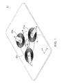
- Fig. 1 is a plan view of an embodiment of a three-axis antenna according to the present invention.
- Figs. 2A and 2B are a plan view and a sectional view thereof, for showing an antenna coil employed in the three-axis antenna.
- the three-axis antenna 11 contains an antenna coil 21 having three planar antenna coils 21a, 21b and 21c arranged on the x-y plane.
- the antenna coils 21a, 21b and 21c include, as shown in Figs. 2A (plan view) and 2B (sectional view), a flat-shaped planar coil 31 of an inner diameter do, an outer diameter d 1 and a thickness t 31 formed of insulated wire wound around a winding axis N, and a rectangular sheet shaped sheet core 41 of a length L, a width W, a thickness t 41 , inserted into the central hole 31a of the planar coil 31.
- the planar coil 31 is wound around a winding axis N to make the central hole 31a at the center, and the sheet core 41 is inserted into the central hole 31a.
- the sheet core 41 is a rectangular foil-type core, which is configured by forming a thin film of soft magnetic material on a sheet-like PET base material, and is inclined at about 90° to the winding axis N of the planar coil 31.
- the sheet core 41 and the planar coil 31 overlap each other so that the lower surface at one end of the sheet core contacts the upper surface of the planar coil 31, and the upper surface at the other end of the sheet core 41 contacts the lower surface of the planar coil 31.
- the three-axis antenna 11 is arranged such that the a axis, the b axis and the c axis cross at the point of origin 0, and the centers P are positioned on the circle of radius R and with the center in the point of origin 0 so that the axes a, b and c make an angle of 120° with each other.
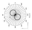
- Fig. 3 is a graph showing the radiation characteristics of the antenna coils 21.
- the axial direction of the sheet core 41 is designated as the x direction and the winding direction of the planar coil 31 is designated as z axis.
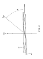
- the direction of the maximum reception sensitivity namely, the direction generating the maximum induced voltage V max forms an inclination angle ⁇ (0° ⁇ 6 ⁇ 90°) to the axial direction (x axis) of the sheet core 41, as shown in Fig. 4 .
- the angle ⁇ in Fig. 4 is about 50°.
- the reception sensitivity is defined as the induced voltage generated in an antenna coil when the antenna coil is located in the magnetic field of 1 ⁇ T.
- the inclination angle ⁇ can be adjusted by varying the shape of the sheet core 41, the relative permeability ⁇ r , etc. Namely, the inclined angle ⁇ will be smaller if the length L of the axial direction of the sheet core 41 is longer, the sectional area W ⁇ t 41 is larger or the relative permeability ⁇ r is increased.
- Fig. 5 is a graph showing the variations of the inclination angle ⁇ and the maximum induced voltage V max when the axial direction length L of the sheet core 41 is modified.
- the abscissa represents the longitudinal length L [mm] of the sheet core
- the ordinate represents the inclination angle ⁇ [°] and the maximum induced voltage V max [V]
- the solid line represents the inclination angle ⁇ and the dotted line represents the maximum induced voltage V max .
- the planar coil employed herein is the same as the planar coil 31 explained in Figs. 2A and 2B .
- Fig. 6 is a characteristics diagram showing the directions of the maximum reception sensitivity of the antenna coils 21a, 21b and 21c (not shown) together with the reception sensitivity of the three-axis antenna 11.
- supposing the longitudinal direction of the sheet core of the antenna coil 21a is the a axis
- the direction of the maximum reception sensitivity is the ⁇ axis
- the inclination angle is ⁇
- supposing the axial direction of the sheet core of the antenna coil 21b is the b axis
- the direction of the maximum reception sensitivity is the ⁇ axis
- the inclination angle is ⁇
- supposing the axial direction of the sheet core of the antenna coil 21c is the c axis
- the direction of the maximum reception sensitivity is the ⁇ axis
- the inclination angle is ⁇
- supposing the a axis is the x axis, the angles between the a axis, the b axis and the c
- the inclination angle ⁇ is formed at 35.26°. From the graph of Fig. 5 , the axial length L of the sheet core 41 for obtaining the inclination angle ⁇ of 35.26° is about 27 mm.
- Fig. 7A shows radiation characteristics of the antenna coil 21a
- Fig. 7B shows radiation characteristics of the antenna coil 21b
- Fig. 7C shows radiation characteristics of the antenna coil 21c
- Fig. 7D shows radiation characteristics of the three-axis antenna 11 as obtained by the logical sum of the radiation characteristics of the antenna coils 21a, 21b and 21c.
- the three-axis antenna 11 is an antenna having omni-directional reception sensitivity.
- such a three-axis antenna 11 that uses the sheet core and the thin planar coil is different from conventional three-axis antennas that use thick ferrite in that a certain flexibility is expected which recommends it for incorporation into an IC card, etc.
- the inclined angle of 35.26° is ideal in theory but the antenna coils have reception sensitivity even slightly away from the maximum reception sensitivity direction. Therefore, even if there are slight differences in the inclined angle ⁇ and the arrangement of the antenna coils, the areas lacking reception sensitivity are mutually complementary ensuring that the antenna is omni-directional.
- a three-axis antenna coil can be an antenna coil having H-shaped planar profile sheet core which combines a plurality of sheet-like core pieces.
- Fig. 8 is a plan view of an antenna coil which is employed in the second embodiment of the present invention.
- an antenna coil 22 includes a planar coil 32, and an H-shaped sheet core 42 inserted into a central hole 31a of the planar coil 32.
- the sheet core 42 consists of a rectangular sheet core piece 42a, and two sheet-like core pieces 42b, 42b, of a semi-circular shape which are positioned at opposite ends of the core piece 42a.
- the planar coil 32 is the same as the planar coil 31 described in the first embodiment.
- the core piece 42a has a length L 42a , a width W 42a , and a thickness t 42
- the core piece 42b has a diameter L 42a , and a height of arc W 42b .
- the antenna coil 22 can be easily positioned without overlapping.
- a three-axis antenna coil can use, as shown in Fig. 9 , an antenna coil configured by combining a plurality of sheet-like core pieces to form a T-shaped sheet core.
- Fig. 9 is a detailed plan view showing an antenna coil employed in the third embodiment of the present invention.
- an antenna coil 23 includes a planar coil 33, a sheet core 43 of a T-shaped planar profile which is inserted into the central hole of the planar coil 33, and the sheet core 43 includes a rectangular sheet core piece 43a and a rectangular sheet core piece 43b arranged at one end of the core piece 43a.
- the planar coil 33 is the same as the planar coil 31 in the first embodiment.
- the core piece 43a has a length L 43a , a width W 43a and a thickness t 43
- the core piece 43b has a length L 43b , a width W 43b and a thickness t 43 .
- the antenna coil 23 is asymmetrical but the radiation characteristic is symmetrical.
- a sheet core may have various shapes for attaining desired characteristics, and has many choices.
- a single sheet core may be employed or combined plural sheets may also be employed for ease of assembly.
- the reception sensitivity of the three-axis antenna according to the present invention is affected by electro-magnetic coupling among the antenna coils.
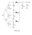
- Fig. 10 shows a circuit configuration to simulate internal influences in the three-axis antenna when electro-magnetic coupling occurs among the antenna coils.
- the antenna coils L1, L2 and L3 are connected with resonant capacitors C1, C2 and C3 in parallel, respectively, and the outputs of the antenna coils L1, L2 and L3, connected in parallel to the capacitor Cout and the resistor Rout are connected, via the diodes D1, D2 and D3, to the terminal which outputs the voltage Vout.
- a voltage source V1 a voltage induced by an external magnetic field, is connected to the antenna coil L1.
- the abscissa represents the coupling coefficient K [%] and the ordinate represents the normalized output voltage Vout when the output voltage Vout is normalized as 100[%] and the coupling coefficient is zero.
- the output voltage Vout lowers 8% when the coupling coefficient K is 2%, and the output voltage Vout drops 71% when the coupling coefficient K is 10%.
- the coupling coefficient should be less than 2% and as close as possible to 0%.
- Fig. 12 is a plan view showing the fourth embodiment of the present invention.
- the fourth embodiment is mostly similar to the first embodiment, but is different therefrom in that the directions of the axes a, b and c of the sheet core 41 of the antenna coils 21a, 21b and 21c are rotated by the angle of ⁇ degrees around the centers P of the respective antenna coils.
- the angles among the axes a, b and c are kept at 120°.
- Fig. 13 is a graph showing the coupling coefficient K among the antenna coils when the length L of the sheet core 41 is 20 mm or 27 mm and rotating an antenna coil by ⁇ (0° ⁇ 90°), as in Fig. 12 .
- the abscissa represents the angle of rotation ⁇ [°]
- the ordinate represents the coupling coefficient K [%].
- the coupling coefficient K among antenna coils varies depending on the rotation angle ⁇ , and the rotation angle ⁇ at which the coupling coefficient is minimized varies depending on the shape of the sheet core.
- Fig. 14 is a plan view of the fifth embodiment of the present invention.
- the fifth embodiment is configured by applying the antenna coil 22 of the second embodiment to the antenna coils of the fourth embodiment.
- the antenna coils 22a, 22b and 22c are the same as the antenna coil 22 described in the second embodiment.
- the abscissa represents the rotation angle ⁇ [°]
- the ordinate represents the coupling coefficient K [%].
- Fig. 16 is a plan view of the sixth embodiment of the present invention.
- the sixth embodiment is configured by applying the antenna coil 23 of the third embodiment to the antenna coils of the fourth embodiment.
- the antenna coils 23a, 23b and 23c are the same as the antenna coil 23 described in the third embodiment.
- Fig. 17 is a graph showing the coupling coefficient K among the antenna coils, which are rotated by the angle ⁇ (0° ⁇ 180°) as shown in Fig. 16 .
- the abscissa represents the rotation angle ⁇ [°]
- the ordinate represents the coupling coefficient K [%].
- the coupling coefficient K varies depending on the rotation angle ⁇ , and is nearly zero when the rotation angle is about 50° or 100°.
- the coupling coefficient K varies depending on the rotation angle ⁇ which minimum value varies in relation to the shape of the sheet core.
- Fig. 18 is a plan view of the seventh embodiment of the present invention.
- the antenna coils 24a, 24b and 24c are arranged so that the centers P of the antenna coils are collinear, and the a axis, the b axis and the c axis of the respective sheet cores form an angle of 120° between each other.
- the antenna coils 24a, 24b and 24c are the same as the antenna coil 22 described in the second embodiment.
- Fig. 19 is a graph showing the coupling coefficient K between the respective antenna coils when rotated by an angle ⁇ (0° ⁇ 180°).
- the abscissa represents the rotation angle ⁇ [°]
- the ordinate represents the coupling coefficient K [%]
- the coupling coefficient between the antenna coil 24a and the antenna coil 24b is K12
- the coupling coefficient between the antenna coil 24b and the antenna coil 24c is K23
- the coupling coefficient between the antenna coil 24a and the antenna coil 24c is K13.
- the rotation angle by adjusting the rotation angle while maintaining the angle of 120° between the axial directions of the respective antenna coils even if the antenna coils are positioned closely together, the coupling among the antenna coils can be minimized and a three-axis antenna of slightly decreased receiving sensitivity is obtained. As a result, a three-axis antenna which requires a smaller area is available. It is important that the respective antenna coils do not overlap each other.
- the material of the sheet core has been described as a softly magnetic thin film on PET base material, however, various materials, including ferrite in sheet or plate, form metallic magnetic resin impregnated with metallic magnetic powder, etc., are applicable to the present invention.
- the positioning of the antenna coils without limiting to positions where the centers P are concentric or collinear, they can be freely arranged as long as the antenna coils do not overlap each other, including an arrangement where coplanar antenna coils are positioned on the top and bottom surfaces of a circuit board.
- the present invention relates to a three-axis antenna suitable for incorporating in a thin article such as IC cards.
- a three-axis antenna suitable for incorporating in a thin article such as IC cards.
- the present invention is applicable to transmission antennas or various antennas, without being limited to reception antennas.
Landscapes
- Engineering & Computer Science (AREA)
- Computer Security & Cryptography (AREA)
- Radar, Positioning & Navigation (AREA)
- Remote Sensing (AREA)
- Variable-Direction Aerials And Aerial Arrays (AREA)
Abstract
Description
- The present invention relates to an omni-directional reception sensitivity three-axis antenna which is used in a receiving device of a keyless entry system for locking or unlocking a vehicle, etc.
- As an antenna for LF band, a bar antenna which consists of wire wound around a bar-type core winding axis is used. Such a bar antenna has a reception sensitivity in the direction of the winding axis and does not have that in directions orthogonal to the winding axis. Therefore, as plural antenna coils mutually compensate for their respective area which lacks reception sensitivity by arranging three antenna coils such that the respective winding axes orthogonally cross each other, an antenna having omni-directional reception sensitivity is obtained.
- In recent years, a small-sized three-axis antenna, having three coils wound orthogonally to each other around a single core, as shown in Japanese patent laid-open No.
2004-15168 -
Fig. 20 shows an example of a prior art three-axis antenna. As shown inFig. 20 , a conventional three-axis antenna 70 is configured by acore 80 consisting of an externally flat disk-type ferrite core 80, on which circumference surface, mutually orthogonally crossing on the top and bottom surfaces of thecore 80, anx groove 81, a ygroove 82 and a zgroove 83 are provided, with anx axis coil 91, a yaxis coil 92 and a zaxis coil 93 respectively wound around thex groove 81, they groove 82 and thez groove 83. - The three-
axis antenna 70 has omni-directional reception sensitivity due to the winding axes of thex axis coil 91, they axis coil 92 and thez axis coil 93 being orthogonal to each other. - Although the above-mentioned prior art three-axis antenna is low-profiled, its thickness still exceeds 3 mm. Thus, it may be incorporated in a key holder or the like, but not in a thin article like an IC card standardized at 85.6 mm width, 54.0 mm height and 0.76 mm thickness.
- The present invention is characterized by the provision of:
- A three-axis antenna comprising a first through a third antenna coils each of which comprises: a planar coil wound around a winding axis circumferentially to form a central hole or aperture, and a core, such as a sheet or foil-type core, inserted into the central hole,
wherein
the first through the third antenna coils are arranged in a manner that the respective antenna coils do not overlap each other, and the planes of the planar coils make one plane, and the axes of the respective sheet cores of the first through third antenna coils cross each other at angle of 120° each. - It is understood that references in the description and claims to the axial directions of the cores forming an angle of 120° to each other is intended to refer to these cores being substantially equally spaced in the plane in which they are located, such that the angle between the axis of each pair of cores is substantially 120°. However, the exact angle may depart from 120° by a small amount while still achieving substantially the same function.
- According to the three-axis antenna of the present invention, a three-axis antenna which can be incorporated in a thin article like an IC card, etc. may be obtained.
-
-
Fig. 1 is a perspective view of the first embodiment of the three-axis antenna of the present invention; -
Fig. 2A is a plan view of an antenna coil in the embodiment; -
Fig. 2B is a longitudinal sectional view of the antenna coil; -
Fig. 3 is a graph showing the radiation characteristics of the antenna coil; -
Fig. 4 is a sectional view showing the radiation characteristics of the antenna coil; -
Fig. 5 is a graph showing the characteristics of the antenna coil; -
Fig. 6 is a characteristics diagram showing the direction of the maximum reception sensitivity of the three-axis antenna according to the present invention; -
Figs. 7A through 7D show simulations of the radiation characteristics of the three-axis antenna according to the present invention; -
Fig. 8 is a plan view of the second embodiment of the present invention; -
Fig. 9 is a plan view of the third embodiment of the present invention; -
Fig. 10 is a circuit diagram explaining electro-magnetic coupling between the antenna coils of the three-axis antennas; -
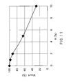
Fig. 11 is a graph showing the relationship between the coupling coefficient among the antenna coils of the three-axis antenna and the output voltage; -
Fig. 12 is a plan view of the fourth embodiment of the present invention; -
Fig. 13 is a graph showing the relationship between the rotation angle and the coupling coefficient of the three-axis antenna shown inFig. 12 ; -
Fig. 14 is a plan view of the fifth embodiment of the present invention; -
Fig. 15 is a graph showing the relationship between the rotation angle and the coupling coefficient of the three-axis antenna shown inFig. 14 ; -
Fig. 16 is a plan view of the sixth embodiment of the present invention; -
Fig. 17 is a graph showing the relationship between the rotation angle and the coupling coefficient of the three-axis antenna shown inFig. 16 ; -
Fig. 18 is a plan view of the seventh embodiment of the present invention; -
Fig. 19 is a graph showing the relationship between the rotation angle and the coupling coefficient of the three-axis antenna shown inFig. 18 ; and -
Fig. 20 is a perspective view of a conventional three-axis antenna. -
Fig. 1 is a plan view of an embodiment of a three-axis antenna according to the present invention.Figs. 2A and 2B are a plan view and a sectional view thereof, for showing an antenna coil employed in the three-axis antenna. - As shown in
Fig. 1 , the three-axis antenna 11 contains anantenna coil 21 having threeplanar antenna coils - The
antenna coils Figs. 2A (plan view) and 2B (sectional view), a flat-shapedplanar coil 31 of an inner diameter do, an outer diameter d1 and a thickness t31 formed of insulated wire wound around a winding axis N, and a rectangular sheetshaped sheet core 41 of a length L, a width W, a thickness t41 , inserted into thecentral hole 31a of theplanar coil 31. Theplanar coil 31 is wound around a winding axis N to make thecentral hole 31a at the center, and thesheet core 41 is inserted into thecentral hole 31a. - The
sheet core 41 is a rectangular foil-type core, which is configured by forming a thin film of soft magnetic material on a sheet-like PET base material, and is inclined at about 90° to the winding axis N of theplanar coil 31. Thesheet core 41 and theplanar coil 31 overlap each other so that the lower surface at one end of the sheet core contacts the upper surface of theplanar coil 31, and the upper surface at the other end of thesheet core 41 contacts the lower surface of theplanar coil 31. - Designating the respective centers of the
antenna coils Fig. 2A ) and 43 (Fig. 9 ) as a axis, b axis and c axis (refer toFig.1 ), the three-axis antenna 11 is arranged such that the a axis, the b axis and the c axis cross at the point oforigin 0, and the centers P are positioned on the circle of radius R and with the center in the point oforigin 0 so that the axes a, b and c make an angle of 120° with each other. - Hereunder, the omni-directionality of the three-
axis antenna 11 and the conditions thereof will be explained. -
Fig. 3 is a graph showing the radiation characteristics of theantenna coils 21. InFig. 3 , the axial direction of thesheet core 41 is designated as the x direction and the winding direction of theplanar coil 31 is designated as z axis. - Here, the
planar coil 31 is constructed by winding, for 332 turns, self-fusion wire of 0.045 mm diameter, with an inner diameter d0=8mm, an outer diameter d1=19 mm, a thickness t31=0.2 mm, and thesheet core 41 has a relative permeability µr = 104, a length L=20 mm, a width W=6 mm and a thickness t41=0.060 mm. - Conventional bar-type antennas wound around a bar-type core have maximum reception sensitivity and generate maximum induced voltage in the axial direction. On the contrary, in the
antenna coils 21 shown inFig. 1 , the direction of the maximum reception sensitivity, namely, the direction generating the maximum induced voltage Vmax forms an inclination angle θ (0°≦6≦90°) to the axial direction (x axis) of thesheet core 41, as shown inFig. 4 . The angle θ inFig. 4 is about 50°. - Here, the reception sensitivity is defined as the induced voltage generated in an antenna coil when the antenna coil is located in the magnetic field of 1 µT.
- The inclination angle θ, together with the maximum induced voltage Vmax, can be adjusted by varying the shape of the
sheet core 41, the relative permeability µr, etc. Namely, the inclined angle θ will be smaller if the length L of the axial direction of thesheet core 41 is longer, the sectional area W×t41 is larger or the relative permeability µr is increased. -
Fig. 5 is a graph showing the variations of the inclination angle θ and the maximum induced voltage Vmax when the axial direction length L of thesheet core 41 is modified. InFig. 5 , the abscissa represents the longitudinal length L [mm] of the sheet core, and the ordinate represents the inclination angle θ [°] and the maximum induced voltage Vmax [V], wherein the solid line represents the inclination angle θ and the dotted line represents the maximum induced voltage Vmax. The planar coil employed herein is the same as theplanar coil 31 explained inFigs. 2A and 2B . - It is understood from
Fig. 5 that the longer the longitudinal length L of thesheet core 41 is, the smaller the inclination angle θ and the larger the maximum induced voltage Vmax are. -
Fig. 6 is a characteristics diagram showing the directions of the maximum reception sensitivity of theantenna coils axis antenna 11. InFig. 6 , supposing the longitudinal direction of the sheet core of theantenna coil 21a is the a axis, the direction of the maximum reception sensitivity is the α axis, and the inclination angle is θ, supposing the axial direction of the sheet core of theantenna coil 21b is the b axis, the direction of the maximum reception sensitivity is the β axis, and the inclination angle is θ, supposing the axial direction of the sheet core of theantenna coil 21c is the c axis, the direction of the maximum reception sensitivity is the γ axis, and the inclination angle is θ, and supposing the a axis is the x axis, the angles between the a axis, the b axis and the c axis are 120°, respectively, and the axes cross each other at the point oforigin 0. - As shown in
Fig. 6 , since the α axis, the β axis and the γ axis need to cross each other orthogonally in order to render the three-axis antenna 11 omni-directional, the inclination angle θ is formed at 35.26°. From the graph ofFig. 5 , the axial length L of thesheet core 41 for obtaining the inclination angle θ of 35.26° is about 27 mm. -
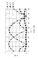
Figs. 7A through 7D show radiation characteristics as results of simulations on theantenna coils axis antenna 11, wherein -
Fig. 7A shows radiation characteristics of theantenna coil 21a, -
Fig. 7B shows radiation characteristics of theantenna coil 21b, -
Fig. 7C shows radiation characteristics of theantenna coil 21c, and -
Fig. 7D shows radiation characteristics of the three-axis antenna 11 as obtained by the logical sum of the radiation characteristics of theantenna coils - As shown in
Fig. 7D , the three-axis antenna 11 is an antenna having omni-directional reception sensitivity. - The thickness T (=t31+t41×2, shown in
Fig. 2B ) of the abovementioned antenna coil is about 0.32 mm. This is thinner than the thickness of the base material, obtained by excluding the respective 0. 20 mm thicknesses of the top and bottom surfaces of the exterior from the thickness 0.76 mm of an IC card, so that the three-axis antenna 11 can be embedded into an IC card. - In addition, such a three-
axis antenna 11 that uses the sheet core and the thin planar coil is different from conventional three-axis antennas that use thick ferrite in that a certain flexibility is expected which recommends it for incorporation into an IC card, etc. - Besides, the inclined angle of 35.26° is ideal in theory but the antenna coils have reception sensitivity even slightly away from the maximum reception sensitivity direction. Therefore, even if there are slight differences in the inclined angle θ and the arrangement of the antenna coils, the areas lacking reception sensitivity are mutually complementary ensuring that the antenna is omni-directional.
- The shape of a sheet core is not limited to being rectangular. As shown in
Fig. 8 , a three-axis antenna coil can be an antenna coil having H-shaped planar profile sheet core which combines a plurality of sheet-like core pieces. -
Fig. 8 is a plan view of an antenna coil which is employed in the second embodiment of the present invention. As shown inFig. 8 , anantenna coil 22 includes aplanar coil 32, and an H-shapedsheet core 42 inserted into acentral hole 31a of theplanar coil 32. Thesheet core 42 consists of a rectangularsheet core piece 42a, and two sheet-like core pieces core piece 42a. Theplanar coil 32 is the same as theplanar coil 31 described in the first embodiment. Thecore piece 42a has a length L42a, a width W42a, and a thickness t42, and thecore piece 42b has a diameter L42a, and a height of arc W42b. - Since the
sheet core 42's outline is made to fit that of theplanar coil 32, theantenna coil 22 can be easily positioned without overlapping. - A three-axis antenna coil can use, as shown in
Fig. 9 , an antenna coil configured by combining a plurality of sheet-like core pieces to form a T-shaped sheet core. -
Fig. 9 is a detailed plan view showing an antenna coil employed in the third embodiment of the present invention. - As shown in
Fig. 9 , anantenna coil 23 includes aplanar coil 33, asheet core 43 of a T-shaped planar profile which is inserted into the central hole of theplanar coil 33, and thesheet core 43 includes a rectangularsheet core piece 43a and a rectangularsheet core piece 43b arranged at one end of thecore piece 43a. Theplanar coil 33 is the same as theplanar coil 31 in the first embodiment. Thecore piece 43a has a length L43a, a width W43a and a thickness t43, and thecore piece 43b has a length L43b, a width W43b and a thickness t43. In relation to the axial direction of the sheet core 43 (x axis inFig. 9 ), theantenna coil 23 is asymmetrical but the radiation characteristic is symmetrical. - As described in the first through third embodiments, a sheet core may have various shapes for attaining desired characteristics, and has many choices. Thus, a single sheet core may be employed or combined plural sheets may also be employed for ease of assembly.
- In a conventional three-axis antenna in
Fig. 20 , no electro-magnetic coupling occurs among the three antenna coils. However, in a three-axis antenna which realizes omni-directional antenna by combining a plurality of bar antennas, electro-magnetic coupling will occur when antenna coils are arranged closely, and as a result, the reception sensitivity of an antenna will be affected. - Similarly, the reception sensitivity of the three-axis antenna according to the present invention is affected by electro-magnetic coupling among the antenna coils. The shorter the distances among the antenna coils are, the stronger the electro-magnetic coupling is. Therefore, the miniaturization of a three-axis antenna is rather difficult.
-
Fig. 10 shows a circuit configuration to simulate internal influences in the three-axis antenna when electro-magnetic coupling occurs among the antenna coils. The antenna coils L1, L2 and L3 are connected with resonant capacitors C1, C2 and C3 in parallel, respectively, and the outputs of the antenna coils L1, L2 and L3, connected in parallel to the capacitor Cout and the resistor Rout are connected, via the diodes D1, D2 and D3, to the terminal which outputs the voltage Vout. A voltage source V1, a voltage induced by an external magnetic field, is connected to the antenna coil L1. - Here, let us designate the coupling coefficient between the antenna coils L1 and L2 as K12, the coupling coefficient between the antenna coils L2 and L3 as K23, and the coupling coefficient between the antenna coils L3 and L1 as K31.
-
Fig. 11 is a graph showing the result of simulating the output voltage Vout when the coupling coefficient K varies from 0% to 10%, provided that K12=K23=K31=K. The abscissa represents the coupling coefficient K [%] and the ordinate represents the normalized output voltage Vout when the output voltage Vout is normalized as 100[%] and the coupling coefficient is zero. - As shown in
Fig. 11 , the output voltage Vout lowers 8% when the coupling coefficient K is 2%, and the output voltage Vout drops 71% when the coupling coefficient K is 10%. - In this manner, the electro-magnetic coupling between antenna coils deteriorates the reception sensitivity. Preferably, the coupling coefficient should be less than 2% and as close as possible to 0%.
-
Fig. 12 is a plan view showing the fourth embodiment of the present invention. The fourth embodiment is mostly similar to the first embodiment, but is different therefrom in that the directions of the axes a, b and c of thesheet core 41 of theantenna coils - As the three
antenna coils -
Fig. 13 is a graph showing the coupling coefficient K among the antenna coils when the length L of thesheet core 41 is 20 mm or 27 mm and rotating an antenna coil by ψ (0°≦ψ≦90°), as inFig. 12 . InFig. 13 , the abscissa represents the angle of rotation ψ [°], and the ordinate represents the coupling coefficient K [%]. - The radius is R=12 mm, and dimensions of the
sheet core 41 are the width W=6 mm and the thickness t41=0.060 mm. - From the results depicted in
Fig. 13 , it is understood that the coupling coefficient K among the antenna coils varies according to the rotation angle ψ,
in the case the length L of thesheet core 41 is 20 mm, the coupling coefficient K is minimum at the rotation angle ψ=90°, and
in the case that the length L of thesheet core 41 is 27 mm, the coupling coefficient K is nearly 0 at the rotation angle ψ=60°. - As the antenna coil has a shape symmetrical in relation to an axis orthogonal to the axial direction of the sheet core, in the graph of
Fig. 13 the coupling coefficient K in the case that the rotation angle ψ>90° becomes symmetrical when ψ=90°. - Thus, the coupling coefficient K among antenna coils varies depending on the rotation angle ψ, and the rotation angle ψ at which the coupling coefficient is minimized varies depending on the shape of the sheet core.
-
Fig. 14 is a plan view of the fifth embodiment of the present invention. The fifth embodiment is configured by applying theantenna coil 22 of the second embodiment to the antenna coils of the fourth embodiment. The antenna coils 22a, 22b and 22c are the same as theantenna coil 22 described in the second embodiment. -
Fig. 15 is a graph showing the coupling coefficient K among theantenna coils Fig. 14 . - In
Fig. 15 , the abscissa represents the rotation angle ψ [°], and the ordinate represents the coupling coefficient K [%]. The antenna coils 22a, 22b and 22c are configured by the dimensions W42a=6mm, L42a=20mm, W42b=8mm and t42=0.060mm. - As shown in
Fig. 15 , the coupling coefficient K varies depending on the rotation angle ψ, and in the cases of R=12mm and R=13mm, the coupling coefficient K is nearly zero at the rotation angle ψ=60°, and in the case of radius R=11mm, the coupling coefficient can be minimized at the rotation angle ψ=70°. - The reason the coupling coefficient does not become zero at radius R=11mm is that the sheet cores of the antenna coils are overlapped each other.
- As described above, not only the coupling coefficient K becomes smaller if radius R is increased, it also varies depending on the rotating angle ψ.
-
Fig. 16 is a plan view of the sixth embodiment of the present invention. The sixth embodiment is configured by applying theantenna coil 23 of the third embodiment to the antenna coils of the fourth embodiment. The antenna coils 23a, 23b and 23c are the same as theantenna coil 23 described in the third embodiment. -
Fig. 17 is a graph showing the coupling coefficient K among the antenna coils, which are rotated by the angle ψ (0°≦ψ≦180°) as shown inFig. 16 . InFig. 17 , the abscissa represents the rotation angle ψ [°], and the ordinate represents the coupling coefficient K [%]. Besides, the radius R=12mm, and theantenna coils - As shown in
Fig. 17 , the coupling coefficient K varies depending on the rotation angle ψ, and is nearly zero when the rotation angle is about 50° or 100°. - As described above, the coupling coefficient K varies depending on the rotation angle ψ which minimum value varies in relation to the shape of the sheet core. In addition, in the case the sheet core is not symmetrical in relation to an axis orthogonal to the axial direction of the sheet core, the graph of the coupling coefficient K is not symmetrical in relation to the rotation angle ψ=90° as shown in the graph of
Fig.13 . -
Fig. 18 is a plan view of the seventh embodiment of the present invention. The antenna coils 24a, 24b and 24c are arranged so that the centers P of the antenna coils are collinear, and the a axis, the b axis and the c axis of the respective sheet cores form an angle of 120° between each other. The antenna coils 24a, 24b and 24c are the same as theantenna coil 22 described in the second embodiment. -
Fig. 19 is a graph showing the coupling coefficient K between the respective antenna coils when rotated by an angle ψ (0°≦ψ≦180°). InFig. 19 , the abscissa represents the rotation angle ψ [°], and the ordinate represents the coupling coefficient K [%],
the coupling coefficient between theantenna coil 24a and theantenna coil 24b is K12,
the coupling coefficient between theantenna coil 24b and theantenna coil 24c is K23, and
the coupling coefficient between theantenna coil 24a and theantenna coil 24c is K13. - As shown in
Fig. 19 , the coupling coefficient K varies depending on the rotation angle ψ. Note that, as shown in the fourth through sixth embodiments, the coupling coefficients of the antenna coils are not all the same, and they are different for each antenna coil. When the rotation angle ψ is about 150°, the coupling coefficients are K12=0.11, K23=0.32 and K31=0.12. - Thus, there is an optimal rotation angle ψ which minimizes the coupling coefficients between the antenna coils, regardless the arrangement of the antenna coils.
- As described in the fourth through seventh embodiments, by adjusting the rotation angle while maintaining the angle of 120° between the axial directions of the respective antenna coils even if the antenna coils are positioned closely together, the coupling among the antenna coils can be minimized and a three-axis antenna of slightly decreased receiving sensitivity is obtained. As a result, a three-axis antenna which requires a smaller area is available. It is important that the respective antenna coils do not overlap each other.
- Although the preferable embodiments of the present invention have been described above, the present invention should not be limited to the scope of the protection of the embodiments, and, needless to say, many modifications and alterations within the spirit of the present invention shall be covered by the scope of protection of the present invention.
- For example, the material of the sheet core has been described as a softly magnetic thin film on PET base material, however, various materials, including ferrite in sheet or plate, form metallic magnetic resin impregnated with metallic magnetic powder, etc., are applicable to the present invention. As for the positioning of the antenna coils, without limiting to positions where the centers P are concentric or collinear, they can be freely arranged as long as the antenna coils do not overlap each other, including an arrangement where coplanar antenna coils are positioned on the top and bottom surfaces of a circuit board.
- The present invention relates to a three-axis antenna suitable for incorporating in a thin article such as IC cards. However, without being limited to incorporating in IC cards, the present invention is applicable to transmission antennas or various antennas, without being limited to reception antennas.
-
- 11, 14, 15, 16, 17, 70 three-axis antenna
- 21, 21a, 21b, 21c, 22, 22a, 22b, 22c, 23, 23a, 23b, 24a, 24b, 24c antenna coil
- 31, 32, 33 planar coil
- 41, 42, 43 sheet core
- 42a, 42b, 43a, 43b core piece
- 80 core
- 81, 82, 83 groove
- 91, 92, 93 coil
- a, b, c core axis
- R radius
- L length
- W width
- t thickness
- K coupling coefficient
- ψ rotation angle
Claims (13)
- A three-axis antenna (11) comprising first to third antenna coils (21a, 21b, 21c) each of which comprises a planar coil (31) wound around a winding axis (N) of the planar coil to form a central hole, and a respective core (41) having an axial direction and inserted through the central hole (31a) of the planar coil, wherein
the first to third antenna coils are arranged in a manner that the respective antenna coils do not overlap each other, the planes of the planar coils are coplanar, and the axial directions of the respective cores of the first to third antenna coils intersect to form an angle of 120° with each other. - The three-axis antenna claimed in claim 1, wherein each core is a sheet core comprising a substantially planar sheet of material.
- The three-axis antenna claimed in claim 1 or 2, wherein the cores are arranged such that at least a part of each core is arranged in a plane parallel to the plane of the first to third antenna coils.
- The three-axis antenna claimed in any preceding claim, wherein each sheet core (41) and respective planar coil (31) overlap each other so that a lower surface at one end of the sheet core contacts an upper surface of the planar coil (31), and an upper surface at an opposite end of the sheet core (41) contacts a lower surface of the planar coil (31).
- The three-axis antenna claimed in any preceding claim, wherein
the three antenna coils are arranged in a manner that the planar coils are rotated around the center thereof in a same direction and by a same degree so as to minimize mutual electro-magnetic coupling between each of the first to third antenna coils. - The three-axis antenna claimed in any preceding claim, wherein
the planar coils are arranged in such a manner that the centers thereof lie on a circle. - The three-axis antenna claimed in any of claims 1 to 5, wherein the planar coils are arranged in such a manner that the centers thereof are collinear.
- The three-axis antenna claimed in claim 2, wherein
the sheet cores have rectangular and I-shaped outlines. - The three-axis antenna claimed in claim 2, wherein
the sheet cores are substantially H-shaped. - The three-axis antenna claimed in claim 9, wherein each sheet core comprises a central sheet core piece extending through the central hole of the respective planar coil, and two end pieces arranged perpendicularly to the central sheet core piece at each end of the central sheet core piece.
- The three-axis antenna claimed in claim 9 or 10, wherein the sheet cores comprise end pieces having outlines cut to fit the outlines of the planar coils.
- The three-axis antenna claimed in claim 2, wherein
the sheet cores have T-shaped outlines. - The three-axis antenna claimed in claim 12, wherein each sheet core comprises a central sheet core piece extending through the central hole of the respective planar coil, and an end piece arranged perpendicularly to one end of the central sheet core piece.
Applications Claiming Priority (2)
| Application Number | Priority Date | Filing Date | Title |
|---|---|---|---|
| JP2014099298 | 2014-05-13 | ||
| JP2015057361A JP6179543B2 (en) | 2014-05-13 | 2015-03-20 | 3-axis antenna |
Publications (1)
| Publication Number | Publication Date |
|---|---|
| EP2945221A1 true EP2945221A1 (en) | 2015-11-18 |
Family
ID=53054982
Family Applications (1)
| Application Number | Title | Priority Date | Filing Date |
|---|---|---|---|
| EP15167093.2A Withdrawn EP2945221A1 (en) | 2014-05-13 | 2015-05-11 | Three-axis antenna |
Country Status (5)
| Country | Link |
|---|---|
| US (1) | US9972909B2 (en) |
| EP (1) | EP2945221A1 (en) |
| JP (1) | JP6179543B2 (en) |
| KR (1) | KR102003810B1 (en) |
| CN (1) | CN105098329B (en) |
Families Citing this family (8)
| Publication number | Priority date | Publication date | Assignee | Title |
|---|---|---|---|---|
| KR101638310B1 (en) | 2016-01-20 | 2016-07-12 | (주)에프원테크놀로지 | Three-axis coil antenna and a method of manufacturing the same |
| KR101638311B1 (en) | 2016-02-29 | 2016-07-12 | (주)에프원테크놀로지 | Three-axis coil antenna terminal and a method of manufacturing the same |
| CN105866558B (en) * | 2016-03-23 | 2018-06-12 | 清华大学深圳研究生院 | A kind of zonule lightning monitoring localization method and system |
| KR101816414B1 (en) * | 2016-06-21 | 2018-01-08 | 현대자동차주식회사 | Antenna System using motion sensor and Method for operating thereof |
| FR3071988B1 (en) * | 2017-10-03 | 2020-11-06 | Continental Automotive France | NEAR FIELD COMMUNICATION DEVICE |
| CN108365325B (en) * | 2017-12-28 | 2020-02-07 | 中国电子科技集团公司第二十研究所 | Low-frequency navigation miniaturized magnetic array |
| EP3731245A1 (en) * | 2019-04-24 | 2020-10-28 | Premo, S.A. | Ultra-low-profile low frequency antenna |
| US20210094509A1 (en) * | 2019-09-30 | 2021-04-01 | Nxp B.V. | Systems and methods for access control using field strength |
Citations (6)
| Publication number | Priority date | Publication date | Assignee | Title |
|---|---|---|---|---|
| US6644555B1 (en) * | 1999-05-07 | 2003-11-11 | Njc Innovations | Chip card comprising an antenna |
| US20030222829A1 (en) * | 2002-06-04 | 2003-12-04 | Takahide Kitahara | Reception antenna, core, and portable device |
| US20070091009A1 (en) * | 2003-11-03 | 2007-04-26 | Joachim Lueg-Althoff | Inductive miniature component, especially antenna |
| US20080074270A1 (en) * | 2006-09-22 | 2008-03-27 | Nortel Networks Limited | Three dimensional RF signatures |
| GB2469209A (en) * | 2009-04-03 | 2010-10-06 | Murata Manufacturing Co | Antenna including a coil having two offset and non-overlapping portions |
| DE102012001899A1 (en) * | 2012-02-01 | 2013-08-01 | Bernhard Holldack | Method for detecting, tracking and position-displaying of movable and stationary objects i.e. keys, in e.g. vehicle, involves generating magnetic fields by antenna modules, and calculating position and location of key in control devices |
Family Cites Families (10)
| Publication number | Priority date | Publication date | Assignee | Title |
|---|---|---|---|---|
| EP1968157B1 (en) * | 2004-03-12 | 2011-05-11 | Sumida Corporation | Three-axis antenna |
| JP4634166B2 (en) * | 2005-02-03 | 2011-02-16 | 株式会社東海理化電機製作所 | ANTENNA DEVICE AND PORTABLE DEVICE HAVING THE SAME |
| JP4410145B2 (en) | 2005-04-27 | 2010-02-03 | スミダコーポレーション株式会社 | Antenna coil device and electronic circuit device on which the antenna coil device is mounted |
| WO2006124520A2 (en) * | 2005-05-13 | 2006-11-23 | The Charles Machine Works, Inc. | Dipole locator using multiple measurement points |
| WO2008112577A1 (en) | 2007-03-09 | 2008-09-18 | Proteus Biomedical, Inc. | In-body device having a multi-directional transmitter |
| CN201126858Y (en) | 2007-09-14 | 2008-10-01 | 陕西海通天线有限责任公司 | Shortwave broadband omnidirectional antenna |
| JP5625813B2 (en) * | 2010-08-12 | 2014-11-19 | 株式会社村田製作所 | Communication terminal device |
| US8907760B2 (en) * | 2010-09-09 | 2014-12-09 | Nxp B.V. | Multiple-frequency solutions for remote access systems |
| US8704721B2 (en) * | 2011-08-08 | 2014-04-22 | Rf Technologies, Inc. | Multi-axial resonant ferrite core antenna |
| JP6287271B2 (en) | 2014-01-31 | 2018-03-07 | 株式会社村田製作所 | 3-axis antenna |
-
2015
- 2015-03-20 JP JP2015057361A patent/JP6179543B2/en active Active
- 2015-05-11 EP EP15167093.2A patent/EP2945221A1/en not_active Withdrawn
- 2015-05-12 KR KR1020150065865A patent/KR102003810B1/en active Active
- 2015-05-13 US US14/710,630 patent/US9972909B2/en active Active
- 2015-05-13 CN CN201510242731.1A patent/CN105098329B/en active Active
Patent Citations (7)
| Publication number | Priority date | Publication date | Assignee | Title |
|---|---|---|---|---|
| US6644555B1 (en) * | 1999-05-07 | 2003-11-11 | Njc Innovations | Chip card comprising an antenna |
| US20030222829A1 (en) * | 2002-06-04 | 2003-12-04 | Takahide Kitahara | Reception antenna, core, and portable device |
| JP2004015168A (en) | 2002-06-04 | 2004-01-15 | Denso Corp | Receiving antenna, core, portable device |
| US20070091009A1 (en) * | 2003-11-03 | 2007-04-26 | Joachim Lueg-Althoff | Inductive miniature component, especially antenna |
| US20080074270A1 (en) * | 2006-09-22 | 2008-03-27 | Nortel Networks Limited | Three dimensional RF signatures |
| GB2469209A (en) * | 2009-04-03 | 2010-10-06 | Murata Manufacturing Co | Antenna including a coil having two offset and non-overlapping portions |
| DE102012001899A1 (en) * | 2012-02-01 | 2013-08-01 | Bernhard Holldack | Method for detecting, tracking and position-displaying of movable and stationary objects i.e. keys, in e.g. vehicle, involves generating magnetic fields by antenna modules, and calculating position and location of key in control devices |
Also Published As
| Publication number | Publication date |
|---|---|
| US9972909B2 (en) | 2018-05-15 |
| JP2015233271A (en) | 2015-12-24 |
| CN105098329A (en) | 2015-11-25 |
| KR20150130247A (en) | 2015-11-23 |
| US20150333405A1 (en) | 2015-11-19 |
| JP6179543B2 (en) | 2017-08-16 |
| KR102003810B1 (en) | 2019-07-25 |
| CN105098329B (en) | 2020-04-14 |
Similar Documents
| Publication | Publication Date | Title |
|---|---|---|
| EP2945221A1 (en) | Three-axis antenna | |
| US9742066B2 (en) | Antenna device and communication terminal apparatus | |
| US20120038443A1 (en) | Communication terminal | |
| CN106898484B (en) | Wireless communication coil, coil module and mobile terminal using coil module | |
| US8922444B2 (en) | Antenna device and mobile terminal | |
| US20150333532A1 (en) | Wireless power transmitter | |
| JP2007266892A (en) | Coil antenna | |
| US11217372B2 (en) | Coil component | |
| CN109119228B (en) | Pulse transformer | |
| US20120081258A1 (en) | Coil antenna and antenna structure | |
| JP2009296107A (en) | Receiving antenna coil | |
| US9627761B2 (en) | Antenna device, card device, and electronic apparatus | |
| US9312601B2 (en) | Antenna device and communication terminal device | |
| JP2009017593A (en) | Magnetic field antenna, and wireless system and communication system configured using the same | |
| US9543656B2 (en) | Three-axis antenna | |
| US11336014B2 (en) | Antenna device and multiaxial antenna device including antenna device | |
| CN106257750B (en) | Chip antenna and method for manufacturing the same | |
| JP6627252B2 (en) | Antenna device | |
| US10396463B2 (en) | Antenna device | |
| TWI724172B (en) | Antenna device and ic tag using the same | |
| JP2005065151A (en) | Antenna, radio-controlled watch using the same, keyless entry system, rfid tag, and its system | |
| WO2012070678A1 (en) | Antenna, dipole antenna, and communication device utilizing same |
Legal Events
| Date | Code | Title | Description |
|---|---|---|---|
| PUAI | Public reference made under article 153(3) epc to a published international application that has entered the european phase |
Free format text: ORIGINAL CODE: 0009012 |
|
| AK | Designated contracting states |
Kind code of ref document: A1 Designated state(s): AL AT BE BG CH CY CZ DE DK EE ES FI FR GB GR HR HU IE IS IT LI LT LU LV MC MK MT NL NO PL PT RO RS SE SI SK SM TR |
|
| AX | Request for extension of the european patent |
Extension state: BA ME |
|
| 17P | Request for examination filed |
Effective date: 20160511 |
|
| RBV | Designated contracting states (corrected) |
Designated state(s): AL AT BE BG CH CY CZ DE DK EE ES FI FR GB GR HR HU IE IS IT LI LT LU LV MC MK MT NL NO PL PT RO RS SE SI SK SM TR |
|
| RAP1 | Party data changed (applicant data changed or rights of an application transferred) |
Owner name: MURATA MANUFACTURING CO., LTD. |
|
| GRAP | Despatch of communication of intention to grant a patent |
Free format text: ORIGINAL CODE: EPIDOSNIGR1 |
|
| STAA | Information on the status of an ep patent application or granted ep patent |
Free format text: STATUS: GRANT OF PATENT IS INTENDED |
|
| INTG | Intention to grant announced |
Effective date: 20180828 |
|
| STAA | Information on the status of an ep patent application or granted ep patent |
Free format text: STATUS: THE APPLICATION IS DEEMED TO BE WITHDRAWN |
|
| 18D | Application deemed to be withdrawn |
Effective date: 20190108 |