EP2945204A1 - Battery case - Google Patents
Battery case Download PDFInfo
- Publication number
- EP2945204A1 EP2945204A1 EP13870694.0A EP13870694A EP2945204A1 EP 2945204 A1 EP2945204 A1 EP 2945204A1 EP 13870694 A EP13870694 A EP 13870694A EP 2945204 A1 EP2945204 A1 EP 2945204A1
- Authority
- EP
- European Patent Office
- Prior art keywords
- foam material
- battery case
- reinforcing member
- case
- lower case
- Prior art date
- Legal status (The legal status is an assumption and is not a legal conclusion. Google has not performed a legal analysis and makes no representation as to the accuracy of the status listed.)
- Granted
Links
- 230000003014 reinforcing effect Effects 0.000 claims abstract description 33
- 239000006261 foam material Substances 0.000 claims abstract description 32
- 239000011347 resin Substances 0.000 description 15
- 229920005989 resin Polymers 0.000 description 15
- 239000000463 material Substances 0.000 description 12
- 239000013585 weight reducing agent Substances 0.000 description 5
- 238000010586 diagram Methods 0.000 description 4
- 229910000831 Steel Inorganic materials 0.000 description 3
- 238000007789 sealing Methods 0.000 description 3
- 239000003566 sealing material Substances 0.000 description 3
- 239000010959 steel Substances 0.000 description 3
- XEEYBQQBJWHFJM-UHFFFAOYSA-N Iron Chemical compound [Fe] XEEYBQQBJWHFJM-UHFFFAOYSA-N 0.000 description 2
- 230000000694 effects Effects 0.000 description 2
- 239000006260 foam Substances 0.000 description 2
- 239000002184 metal Substances 0.000 description 2
- 229910052751 metal Inorganic materials 0.000 description 2
- 239000007769 metal material Substances 0.000 description 2
- 238000000465 moulding Methods 0.000 description 2
- 238000010791 quenching Methods 0.000 description 2
- 238000005549 size reduction Methods 0.000 description 2
- 238000003466 welding Methods 0.000 description 2
- 230000006866 deterioration Effects 0.000 description 1
- 238000006073 displacement reaction Methods 0.000 description 1
- 239000000945 filler Substances 0.000 description 1
- 238000010438 heat treatment Methods 0.000 description 1
- 229910052742 iron Inorganic materials 0.000 description 1
- 238000003672 processing method Methods 0.000 description 1
- 230000000171 quenching effect Effects 0.000 description 1
- 230000002787 reinforcement Effects 0.000 description 1
- 238000005496 tempering Methods 0.000 description 1
Images


Classifications
-
- B—PERFORMING OPERATIONS; TRANSPORTING
- B60—VEHICLES IN GENERAL
- B60L—PROPULSION OF ELECTRICALLY-PROPELLED VEHICLES; SUPPLYING ELECTRIC POWER FOR AUXILIARY EQUIPMENT OF ELECTRICALLY-PROPELLED VEHICLES; ELECTRODYNAMIC BRAKE SYSTEMS FOR VEHICLES IN GENERAL; MAGNETIC SUSPENSION OR LEVITATION FOR VEHICLES; MONITORING OPERATING VARIABLES OF ELECTRICALLY-PROPELLED VEHICLES; ELECTRIC SAFETY DEVICES FOR ELECTRICALLY-PROPELLED VEHICLES
- B60L50/00—Electric propulsion with power supplied within the vehicle
- B60L50/50—Electric propulsion with power supplied within the vehicle using propulsion power supplied by batteries or fuel cells
- B60L50/60—Electric propulsion with power supplied within the vehicle using propulsion power supplied by batteries or fuel cells using power supplied by batteries
- B60L50/66—Arrangements of batteries
-
- H—ELECTRICITY
- H01—ELECTRIC ELEMENTS
- H01M—PROCESSES OR MEANS, e.g. BATTERIES, FOR THE DIRECT CONVERSION OF CHEMICAL ENERGY INTO ELECTRICAL ENERGY
- H01M50/00—Constructional details or processes of manufacture of the non-active parts of electrochemical cells other than fuel cells, e.g. hybrid cells
- H01M50/10—Primary casings; Jackets or wrappings
- H01M50/116—Primary casings; Jackets or wrappings characterised by the material
- H01M50/124—Primary casings; Jackets or wrappings characterised by the material having a layered structure
-
- B—PERFORMING OPERATIONS; TRANSPORTING
- B60—VEHICLES IN GENERAL
- B60L—PROPULSION OF ELECTRICALLY-PROPELLED VEHICLES; SUPPLYING ELECTRIC POWER FOR AUXILIARY EQUIPMENT OF ELECTRICALLY-PROPELLED VEHICLES; ELECTRODYNAMIC BRAKE SYSTEMS FOR VEHICLES IN GENERAL; MAGNETIC SUSPENSION OR LEVITATION FOR VEHICLES; MONITORING OPERATING VARIABLES OF ELECTRICALLY-PROPELLED VEHICLES; ELECTRIC SAFETY DEVICES FOR ELECTRICALLY-PROPELLED VEHICLES
- B60L50/00—Electric propulsion with power supplied within the vehicle
- B60L50/50—Electric propulsion with power supplied within the vehicle using propulsion power supplied by batteries or fuel cells
- B60L50/60—Electric propulsion with power supplied within the vehicle using propulsion power supplied by batteries or fuel cells using power supplied by batteries
- B60L50/64—Constructional details of batteries specially adapted for electric vehicles
-
- H—ELECTRICITY
- H01—ELECTRIC ELEMENTS
- H01M—PROCESSES OR MEANS, e.g. BATTERIES, FOR THE DIRECT CONVERSION OF CHEMICAL ENERGY INTO ELECTRICAL ENERGY
- H01M50/00—Constructional details or processes of manufacture of the non-active parts of electrochemical cells other than fuel cells, e.g. hybrid cells
- H01M50/20—Mountings; Secondary casings or frames; Racks, modules or packs; Suspension devices; Shock absorbers; Transport or carrying devices; Holders
- H01M50/218—Mountings; Secondary casings or frames; Racks, modules or packs; Suspension devices; Shock absorbers; Transport or carrying devices; Holders characterised by the material
- H01M50/22—Mountings; Secondary casings or frames; Racks, modules or packs; Suspension devices; Shock absorbers; Transport or carrying devices; Holders characterised by the material of the casings or racks
- H01M50/222—Inorganic material
- H01M50/224—Metals
-
- H—ELECTRICITY
- H01—ELECTRIC ELEMENTS
- H01M—PROCESSES OR MEANS, e.g. BATTERIES, FOR THE DIRECT CONVERSION OF CHEMICAL ENERGY INTO ELECTRICAL ENERGY
- H01M50/00—Constructional details or processes of manufacture of the non-active parts of electrochemical cells other than fuel cells, e.g. hybrid cells
- H01M50/20—Mountings; Secondary casings or frames; Racks, modules or packs; Suspension devices; Shock absorbers; Transport or carrying devices; Holders
- H01M50/233—Mountings; Secondary casings or frames; Racks, modules or packs; Suspension devices; Shock absorbers; Transport or carrying devices; Holders characterised by physical properties of casings or racks, e.g. dimensions
-
- H—ELECTRICITY
- H01—ELECTRIC ELEMENTS
- H01M—PROCESSES OR MEANS, e.g. BATTERIES, FOR THE DIRECT CONVERSION OF CHEMICAL ENERGY INTO ELECTRICAL ENERGY
- H01M2220/00—Batteries for particular applications
- H01M2220/20—Batteries in motive systems, e.g. vehicle, ship, plane
-
- Y—GENERAL TAGGING OF NEW TECHNOLOGICAL DEVELOPMENTS; GENERAL TAGGING OF CROSS-SECTIONAL TECHNOLOGIES SPANNING OVER SEVERAL SECTIONS OF THE IPC; TECHNICAL SUBJECTS COVERED BY FORMER USPC CROSS-REFERENCE ART COLLECTIONS [XRACs] AND DIGESTS
- Y02—TECHNOLOGIES OR APPLICATIONS FOR MITIGATION OR ADAPTATION AGAINST CLIMATE CHANGE
- Y02E—REDUCTION OF GREENHOUSE GAS [GHG] EMISSIONS, RELATED TO ENERGY GENERATION, TRANSMISSION OR DISTRIBUTION
- Y02E60/00—Enabling technologies; Technologies with a potential or indirect contribution to GHG emissions mitigation
- Y02E60/10—Energy storage using batteries
-
- Y—GENERAL TAGGING OF NEW TECHNOLOGICAL DEVELOPMENTS; GENERAL TAGGING OF CROSS-SECTIONAL TECHNOLOGIES SPANNING OVER SEVERAL SECTIONS OF THE IPC; TECHNICAL SUBJECTS COVERED BY FORMER USPC CROSS-REFERENCE ART COLLECTIONS [XRACs] AND DIGESTS
- Y02—TECHNOLOGIES OR APPLICATIONS FOR MITIGATION OR ADAPTATION AGAINST CLIMATE CHANGE
- Y02T—CLIMATE CHANGE MITIGATION TECHNOLOGIES RELATED TO TRANSPORTATION
- Y02T10/00—Road transport of goods or passengers
- Y02T10/60—Other road transportation technologies with climate change mitigation effect
- Y02T10/70—Energy storage systems for electromobility, e.g. batteries
Definitions
- the present invention relates to a battery case.
- An electric vehicle (EV), a plug-in hybrid vehicle (PHV), or the like includes, under its floor, a battery case to house a battery (see Patent Document 1).
- Patent Document 1 Japanese Unexamined Patent Application Publication No. 2011-23230
- the above-mentioned battery case involves a problem that its reinforcement structure against external impact tends to lead to weight increase.
- a battery case in one aspect of the present invention comprises a first casing member, a second casing member to form a closed space together with the first casing member, a foam material provided along an inner wall surface of the closed space, and a reinforcing member provided in the closed space so as to hold the foam material between the reinforcing member and the inner wall surface.
- the reinforcing member may be formed by hot stamping.
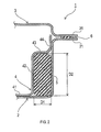
- FIG. 1 is a perspective view of a battery case 1 of the embodiment
- FIG. 2 is a sectional view taken along a line II-II of FIG. 1
- the battery case 1 is disposed under the floor of an automobile 9, such as an electric vehicle (EV) and a plug-in hybrid vehicle (PHV).
- the battery case 1 comprises a lower case 2, an upper case 3, a reinforcing member 4, and a resin foam material 5.
- Each of the lower case 2 and the upper case 3 is a member obtained by processing a metal material (a 270 material having a sheet thickness of 0.7 mm in this example), the member is formed in a container shape having a recessed portion in the center thereof and a generally rectangular bottom surface of the recessed portion.
- the lower case 2 and the upper case 3 are arranged such that their respective recessed sides face each other, to thereby form therein a generally rectangular parallelepiped housing space (a closed space) to house and seal a battery.
- the lower case 2 is shaped to have a depth larger than a depth of the upper case 3, and the upper case 3 serves as a lid of the lower case 2.
- the value "270" of the 270 material represents a tensile strength (a lower limit) of a material. The same is applicable to a later mentioned 590 material.
- a flange 21 is formed at an outer periphery of the lower case 2.
- a flange 31 is formed at an outer periphery of the upper case 3.
- the flanges 21 and 31 have corresponding shapes; the lower case 2 and the upper case 3 are assembled such that their respective flanges 21 and 31 overlap each other.
- a sealing material 6 is provided between the flanges 21 and 31.
- the flanges 21 and 31 serve as a vehicle attachment portion to attach the battery case 1 to the automobile.
- the reinforcing member 4 is formed by hot stamping of a metal material (an iron sheet having a thickness of 2.0 mm in this example).
- Hot stamping is a processing method of a combination of press molding and heat treatment (quenching and tempering) performed using a steel sheet. Through hot stamping, in which a steel sheet is first heated and then quickly cooled concurrently with molding using a die to form a desired shape, it is possible to quench the molded steel sheet to achieve improved strength.
- the reinforcing member 4 is formed in a rectangular annular shape (a frame-like shape) so as to be located along an inner side surface of the lower case 2.
- the reinforcing member 4 comprises a first plate portion 41, a second plate portion 42, a third plate portion 43, and a fourth plate portion 44.
- the first plate portion 41 is welded to a bottom surface of the lower case 2.
- the second plate portion 42 faces the inner side surface of the lower case 2 with a specified distance D1 (for example, 30 mm) therebetween.
- the third plate portion 43 faces the bottom surface of the lower case 2 with a specified distance D2 therebetween.
- the fourth plate portion 44 is welded to the inner side surface of the lower case 2.
- the resin foam material 5 which is a high-rigidity foam filler to be filled in a closed space to thereby provide rigid foam, is filled in a space formed between the lower case 2 and the reinforcing member 4. That is, the resin foam material 5 is formed in a rectangular annular shape (a frame-like shape) so as to be located along an inner wall surface (the bottom surface and the inner side surface) of the lower case 2.
- the battery case 1 comprises the lower case 2, the upper case 3 to form a closed space together with the lower case 2, the resin foam material 5 provided along the inner wall surface (the inner wall surface of the lower case 2), the reinforcing member 4 provided in the closed space so as to hold the resin foam material 5 between the reinforcing member 4 and the inner wall surface of the lower case 2.
- a reinforcing structure using the resin foam material 5 can simplify the reinforcing member 4, it is possible to achieve reduction in the number of components and size reduction of components, and thus to achieve weight reduction.
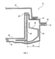
- a battery case 8 shown in FIG. 4 as a conventional example includes an upper case 81 and a lower case 82 made of the same material (a 270 material having a sheet thickness of 0.7 mm) as the material in the above-described embodiment, a plurality of reinforcing members 83, 84, and 85 made of a material (a 590 material having a sheet thickness of 2.0 mm) with higher strength than the material for these cases, and a reinforcing member 86 made of a material (a 590 material having a sheet thickness of 2.3mm) with further higher strength.
- the reinforcing members 83, 84, 85, and 86 are provided outside a housing space that is formed by the upper case 81 and the lower case 82, and sealed with a plurality of sealing materials 87 (provided at four positions in this example).
- a structure to ensure strength only by reinforcing members of sheet metal as described above, it is required to increase the sheet thicknesses of the reinforcing members and/or to increase the number of components, and thus the numbers of welding areas and sealing areas are more likely to be increased. Increase in the numbers of welding areas and sealing areas will lead to weight increase and/or deterioration in waterproof performance.
- the reinforcing member 4 with high strength that is formed by hot stamping is provided in the housing space, it is possible to reduce the number of components to thereby reduce the number of sealing areas (for example, to only one area). Also, consideration on a filling shape of the resin foam material will lead to improved shape retainability of a sectional shape, which will further lead to improved load sharing ability of each of the components. As a result, size reduction and weight reduction may be achieved, and improved waterproof performance may be achieved.
- a width D3 of the reinforcing member needs to be 40 mm or more according to the conventional structure shown in FIG. 4 , in order to obtain a specified reinforcing effect in the battery case.
- a width D1 of the reinforcing member may be reduced to 30 mm ( FIG. 5A ).
- a width dimension that can be used to mount a battery is 740 mm according to the conventional structure shown in FIG. 4
- the width dimension may be 760 mm according to the structure of the present embodiment shown in FIG. 2 ( FIG. 5B ). That is, the structure of the present embodiment allows a larger housing space of the battery case than the conventional structure.
- the lower case 2 which is made of thin sheet metal, is weak against load; however, in the present embodiment, the resin foam material 5 is filled between the lower case 2 and the reinforcing member 4 to thereby increase the sectional strength by almost 50%, while controlling the filling amount to 40% by considering the filling shape ( FIG. 6 ).
- the full plastic moment was confirmed to be 3.8 [kN ⁇ m] in a state without filling; the full plastic moment will be 5.5 [kN ⁇ m] on an assumption of an improvement of 145% as compared with the state without filling of resin (the state where the resin foam material 5 is not filled), and thus it is expected that a strength almost equal to that of the conventional configuration can be obtained ( FIG. 5C ).
- substantial weight reduction can be achieved.
- the weight of the structure of the present embodiment can be reduced to 24.3kg, whereas the weight of the conventional structure shown in FIG. 4 is 43.8 kg ( FIG. 5D ).
- the lower case 2 corresponds to an example of a first casing member
- the upper case 3 corresponds to an example of a second casing member
- the resin foam material 5 corresponds to an example of a foam material.
- the resin foam material 5 is exemplified as the foam material in the above-described embodiment, other foam materials may be employed.
- the shape, the number, or the like, of the foam materials is not particularly limited.
- the foam material may be provided so as to fill the entirety of a fillable space (a space that is formed between the inner wall surface and the reinforcing member in the closed space formed by the first casing member and the second casing member), in which the foam material can be filled.
- a fillable space is not limited to a strict meaning of leaving no gap, but means a state (for example, a state shown in FIG.
- the foam material may be provided so as to fill only part of the fillable space (in other words, such that a space without the foam material is formed) as shown in FIG. 6 , for example, or may be provided in plurality.
- a plurality of (three in this example) resin foam materials 7, each having a circular section i.e., each having a columnar shape in this example
- Various shapes such as a shape having a triangular section, a shape having a rectangular section, a shape having a trapezoidal section, etc., may be employed as the shape of the foam material.
- the configuration including the reinforcing member 4 formed by hot stamping is exemplified in the above-described embodiment, this is not a limitation.
- a configuration without a component formed by hot stamping may be employed, whereas a configuration in which a component formed by hot stamping is used also for the casing member may be employed.
- the present invention may be applied to other purposes than battery cases.
Landscapes
- Engineering & Computer Science (AREA)
- Chemical & Material Sciences (AREA)
- General Chemical & Material Sciences (AREA)
- Chemical Kinetics & Catalysis (AREA)
- Electrochemistry (AREA)
- Sustainable Development (AREA)
- Sustainable Energy (AREA)
- Power Engineering (AREA)
- Transportation (AREA)
- Mechanical Engineering (AREA)
- Life Sciences & Earth Sciences (AREA)
- Inorganic Chemistry (AREA)
- Battery Mounting, Suspending (AREA)
- Sealing Battery Cases Or Jackets (AREA)
- Arrangement Or Mounting Of Propulsion Units For Vehicles (AREA)
- Body Structure For Vehicles (AREA)
Abstract
Description
- This international application claims the benefit of Japanese Patent Application No.
2013-3725 filed January 11, 2013 2013-3725 - The present invention relates to a battery case.
- An electric vehicle (EV), a plug-in hybrid vehicle (PHV), or the like includes, under its floor, a battery case to house a battery (see Patent Document 1).
- Patent Document 1: Japanese Unexamined Patent Application Publication No.
2011-23230 - The above-mentioned battery case involves a problem that its reinforcement structure against external impact tends to lead to weight increase.
- In one aspect of the present invention, it is desirable to enhance weight reduction of a battery case.
- A battery case in one aspect of the present invention comprises a first casing member, a second casing member to form a closed space together with the first casing member, a foam material provided along an inner wall surface of the closed space, and a reinforcing member provided in the closed space so as to hold the foam material between the reinforcing member and the inner wall surface. According to such configuration, use of the foam material enables simplification of the reinforcing member, leading to achievement of weight reduction.
- In the above configuration, the reinforcing member may be formed by hot stamping.
-
-
FIG. 1 is a perspective view of a battery case. -
FIG. 2 is a sectional view taken along a line II-II ofFIG. 1 . -
FIG. 3 is a view showing an example of a mounting position of a battery case in an automobile. -
FIG. 4 is a partial sectional view of a conventional battery case. -
FIG. 5A is a diagram showing numerical examples of widths of reinforcing members. -
FIG. 5B is a diagram showing numerical examples of battery mounting spaces. -
FIG. 5C is a diagram showing numerical examples of full plastic moments. -
FIG. 5D is a diagram showing numerical examples of masses. -
FIG. 6 is a graph showing a relationship between a displacement amount and a load. -
FIG. 7 is a sectional view of a modified example of the battery case. - 1...battery case, 2...lower case, 3...upper case, 4...reinforcing member, 5...resin foam material, 6... sealing material, 7... resin foam material, 9... automobile, 21... flange, 31... flange, 41... first plate portion, 42...second plate portion, 43...third plate portion, 44...fourth plate portion
- Hereinafter, a description will be given of an embodiment, to which the present invention is applied, with reference to the drawings.
-
FIG. 1 is a perspective view of abattery case 1 of the embodiment,FIG. 2 is a sectional view taken along a line II-II ofFIG. 1 . As shown inFIG. 3 , for example, thebattery case 1 is disposed under the floor of anautomobile 9, such as an electric vehicle (EV) and a plug-in hybrid vehicle (PHV). Thebattery case 1 comprises alower case 2, anupper case 3, a reinforcingmember 4, and a resin foam material 5. - Each of the
lower case 2 and theupper case 3 is a member obtained by processing a metal material (a 270 material having a sheet thickness of 0.7 mm in this example), the member is formed in a container shape having a recessed portion in the center thereof and a generally rectangular bottom surface of the recessed portion. Thelower case 2 and theupper case 3 are arranged such that their respective recessed sides face each other, to thereby form therein a generally rectangular parallelepiped housing space (a closed space) to house and seal a battery. Thelower case 2 is shaped to have a depth larger than a depth of theupper case 3, and theupper case 3 serves as a lid of thelower case 2. The value "270" of the 270 material represents a tensile strength (a lower limit) of a material. The same is applicable to a later mentioned 590 material. - A
flange 21 is formed at an outer periphery of thelower case 2. In a similar manner, aflange 31 is formed at an outer periphery of theupper case 3. Theflanges lower case 2 and theupper case 3 are assembled such that theirrespective flanges material 6 is provided between theflanges flanges battery case 1 to the automobile. - The reinforcing
member 4 is formed by hot stamping of a metal material (an iron sheet having a thickness of 2.0 mm in this example). Hot stamping is a processing method of a combination of press molding and heat treatment (quenching and tempering) performed using a steel sheet. Through hot stamping, in which a steel sheet is first heated and then quickly cooled concurrently with molding using a die to form a desired shape, it is possible to quench the molded steel sheet to achieve improved strength. - The reinforcing
member 4 is formed in a rectangular annular shape (a frame-like shape) so as to be located along an inner side surface of thelower case 2. Specifically, the reinforcingmember 4 comprises afirst plate portion 41, asecond plate portion 42, athird plate portion 43, and afourth plate portion 44. Thefirst plate portion 41 is welded to a bottom surface of thelower case 2. Thesecond plate portion 42 faces the inner side surface of thelower case 2 with a specified distance D1 (for example, 30 mm) therebetween. Thethird plate portion 43 faces the bottom surface of thelower case 2 with a specified distance D2 therebetween. Thefourth plate portion 44 is welded to the inner side surface of thelower case 2. - The resin foam material 5, which is a high-rigidity foam filler to be filled in a closed space to thereby provide rigid foam, is filled in a space formed between the
lower case 2 and the reinforcingmember 4. That is, the resin foam material 5 is formed in a rectangular annular shape (a frame-like shape) so as to be located along an inner wall surface (the bottom surface and the inner side surface) of thelower case 2. - According to the embodiment detailed as above, the following effects can be obtained.
- The
battery case 1 comprises thelower case 2, theupper case 3 to form a closed space together with thelower case 2, the resin foam material 5 provided along the inner wall surface (the inner wall surface of the lower case 2), the reinforcingmember 4 provided in the closed space so as to hold the resin foam material 5 between the reinforcingmember 4 and the inner wall surface of thelower case 2. According to the present embodiment, since a reinforcing structure using the resin foam material 5 can simplify the reinforcingmember 4, it is possible to achieve reduction in the number of components and size reduction of components, and thus to achieve weight reduction. - A description will be given of effects of the present embodiment in comparison with a conventional structure. A
battery case 8 shown inFIG. 4 as a conventional example includes anupper case 81 and alower case 82 made of the same material (a 270 material having a sheet thickness of 0.7 mm) as the material in the above-described embodiment, a plurality of reinforcingmembers member 86 made of a material (a 590 material having a sheet thickness of 2.3mm) with further higher strength. The reinforcingmembers upper case 81 and thelower case 82, and sealed with a plurality of sealing materials 87 (provided at four positions in this example). According to a structure to ensure strength only by reinforcing members of sheet metal, as described above, it is required to increase the sheet thicknesses of the reinforcing members and/or to increase the number of components, and thus the numbers of welding areas and sealing areas are more likely to be increased. Increase in the numbers of welding areas and sealing areas will lead to weight increase and/or deterioration in waterproof performance. - In contrast, according to the structure of the present embodiment, in which the reinforcing
member 4 with high strength that is formed by hot stamping is provided in the housing space, it is possible to reduce the number of components to thereby reduce the number of sealing areas (for example, to only one area). Also, consideration on a filling shape of the resin foam material will lead to improved shape retainability of a sectional shape, which will further lead to improved load sharing ability of each of the components. As a result, size reduction and weight reduction may be achieved, and improved waterproof performance may be achieved. For example, a width D3 of the reinforcing member needs to be 40 mm or more according to the conventional structure shown inFIG. 4 , in order to obtain a specified reinforcing effect in the battery case. On the other hand, according to the structure of the present embodiment shown inFIG. 2 , a width D1 of the reinforcing member may be reduced to 30 mm (FIG. 5A ). In a case where an outermost shape of the battery case is L1000 mm×W900 mm, and the width of theflange 83 and the width offlange 31 are both 40 mm, a width dimension that can be used to mount a battery is 740 mm according to the conventional structure shown inFIG. 4 , whereas the width dimension may be 760 mm according to the structure of the present embodiment shown inFIG. 2 (FIG. 5B ). That is, the structure of the present embodiment allows a larger housing space of the battery case than the conventional structure. - The
lower case 2, which is made of thin sheet metal, is weak against load; however, in the present embodiment, the resin foam material 5 is filled between thelower case 2 and the reinforcingmember 4 to thereby increase the sectional strength by almost 50%, while controlling the filling amount to 40% by considering the filling shape (FIG. 6 ). In this case, the full plastic moment was confirmed to be 3.8 [kN·m] in a state without filling; the full plastic moment will be 5.5 [kN·m] on an assumption of an improvement of 145% as compared with the state without filling of resin (the state where the resin foam material 5 is not filled), and thus it is expected that a strength almost equal to that of the conventional configuration can be obtained (FIG. 5C ). - In particular, according to the present embodiment, substantial weight reduction can be achieved. For example, if it is configured such that an outermost shape is L1000 mm×W900 mm and a specified reinforcing effect is achieved in a battery case, the weight of the structure of the present embodiment can be reduced to 24.3kg, whereas the weight of the conventional structure shown in
FIG. 4 is 43.8 kg (FIG. 5D ). - The
lower case 2 corresponds to an example of a first casing member, theupper case 3 corresponds to an example of a second casing member, and the resin foam material 5 corresponds to an example of a foam material. - Although the embodiment of the present invention has been described as above, it is to be understood that the present invention should not be limited to the above-described embodiment, but may be practiced in various forms.
- For example, although the resin foam material 5 is exemplified as the foam material in the above-described embodiment, other foam materials may be employed. Also, the shape, the number, or the like, of the foam materials is not particularly limited. Specifically, the foam material may be provided so as to fill the entirety of a fillable space (a space that is formed between the inner wall surface and the reinforcing member in the closed space formed by the first casing member and the second casing member), in which the foam material can be filled. Here, the expression "fill the entirety of a fillable space" is not limited to a strict meaning of leaving no gap, but means a state (for example, a state shown in
FIG. 2 ) where the shape of the fillable space and the shape of the foam material correspond to each other, and a space without the foam material is not intentionally formed. On the other hand, the foam material may be provided so as to fill only part of the fillable space (in other words, such that a space without the foam material is formed) as shown inFIG. 6 , for example, or may be provided in plurality. In the example shown inFIG. 6 , a plurality of (three in this example)resin foam materials 7, each having a circular section (i.e., each having a columnar shape in this example), are housed. Various shapes, such as a shape having a triangular section, a shape having a rectangular section, a shape having a trapezoidal section, etc., may be employed as the shape of the foam material. - Also, although the configuration including the reinforcing
member 4 formed by hot stamping is exemplified in the above-described embodiment, this is not a limitation. For example, a configuration without a component formed by hot stamping may be employed, whereas a configuration in which a component formed by hot stamping is used also for the casing member may be employed. - Further, the present invention may be applied to other purposes than battery cases.
Claims (2)
- A battery case comprising:a first casing member;a second casing member to form a closed space together with the first casing member;a foam material provided along an inner wall surface of the closed space; anda reinforcing member provided in the closed space so as to hold the foam material between the reinforcing member and the inner wall surface.
- The battery case according to claim 1, wherein the reinforcing member is formed by hot stamping.
Applications Claiming Priority (2)
| Application Number | Priority Date | Filing Date | Title |
|---|---|---|---|
| JP2013003725 | 2013-01-11 | ||
| PCT/JP2013/084863 WO2014109243A1 (en) | 2013-01-11 | 2013-12-26 | Battery case |
Publications (3)
| Publication Number | Publication Date |
|---|---|
| EP2945204A1 true EP2945204A1 (en) | 2015-11-18 |
| EP2945204A4 EP2945204A4 (en) | 2016-06-15 |
| EP2945204B1 EP2945204B1 (en) | 2017-10-25 |
Family
ID=51166899
Family Applications (1)
| Application Number | Title | Priority Date | Filing Date |
|---|---|---|---|
| EP13870694.0A Active EP2945204B1 (en) | 2013-01-11 | 2013-12-26 | Battery case |
Country Status (6)
| Country | Link |
|---|---|
| US (1) | US9761846B2 (en) |
| EP (1) | EP2945204B1 (en) |
| JP (1) | JP5977374B2 (en) |
| CN (1) | CN104919620B (en) |
| CA (1) | CA2897918C (en) |
| WO (1) | WO2014109243A1 (en) |
Cited By (4)
| Publication number | Priority date | Publication date | Assignee | Title |
|---|---|---|---|---|
| WO2018210420A1 (en) * | 2017-05-18 | 2018-11-22 | Thyssenkrupp Steel Europe Ag | Battery housing |
| WO2019121870A1 (en) * | 2017-12-19 | 2019-06-27 | Webasto SE | Housing for receiving battery cells, and method for producing same |
| WO2020038996A1 (en) * | 2018-08-21 | 2020-02-27 | Kirchhoff Automotive Deutschland Gmbh | Battery housing |
| US12330516B2 (en) | 2018-11-12 | 2025-06-17 | Kirchhoff Automotive Deutschland Gmbh | Battery housing for a vehicle operated by electric motor |
Families Citing this family (15)
| Publication number | Priority date | Publication date | Assignee | Title |
|---|---|---|---|---|
| JP6589090B2 (en) * | 2014-11-26 | 2019-10-16 | 三菱自動車工業株式会社 | Battery pack reinforcement structure |
| KR102289582B1 (en) * | 2014-12-30 | 2021-08-13 | 에이치엘그린파워 주식회사 | Battery housing with sealed structure and Method for manufacturing battery module using the same |
| US10358169B2 (en) * | 2015-03-06 | 2019-07-23 | Ford Global Technologies, Llc | Coverless battery assembly for electrified vehicle |
| DE102015003643B3 (en) * | 2015-03-19 | 2016-06-16 | Audi Ag | motor vehicle |
| KR101972135B1 (en) * | 2015-10-29 | 2019-04-24 | 주식회사 엘지화학 | Battery Pack Having Slim Bottom case and Notebook Including the Same |
| JP6255438B2 (en) * | 2016-03-17 | 2017-12-27 | 本田技研工業株式会社 | Battery unit and vehicle |
| DE102016120826B4 (en) | 2016-11-02 | 2018-08-23 | Kirchhoff Automotive Deutschland Gmbh | battery case |
| JP7020804B2 (en) * | 2017-06-19 | 2022-02-16 | 本田技研工業株式会社 | Battery pack |
| JP6891675B2 (en) * | 2017-07-05 | 2021-06-18 | トヨタ自動車株式会社 | Battery-mounted structure |
| JP6859933B2 (en) | 2017-11-17 | 2021-04-14 | トヨタ自動車株式会社 | Vehicle battery case and its manufacturing method |
| DE102018120371B4 (en) * | 2018-08-21 | 2021-07-29 | Kirchhoff Automotive Deutschland Gmbh | Battery housing for a vehicle driven by an electric motor |
| DE102019206408A1 (en) * | 2019-05-03 | 2020-11-05 | Mahle International Gmbh | Housing part |
| JP7650569B2 (en) * | 2021-04-20 | 2025-03-25 | トヨタ自動車株式会社 | Battery pack |
| DE102022122913A1 (en) | 2022-09-09 | 2024-03-14 | Bayerische Motoren Werke Aktiengesellschaft | Electrical energy storage for a motor vehicle and method for producing such an electrical energy storage |
| US20240258623A1 (en) * | 2023-01-31 | 2024-08-01 | Toyota Motor Engineering & Manufacturing North America, Inc. | Battery pack frame assemblies |
Family Cites Families (12)
| Publication number | Priority date | Publication date | Assignee | Title |
|---|---|---|---|---|
| GB188355A (en) * | 1921-07-05 | 1922-11-06 | Samuel Trench | A shock proof accumulator case |
| GB1428132A (en) * | 1972-07-20 | 1976-03-17 | Post Office | Method of constructing double-skin boxes particularly for lead- acid batteries |
| GB1488116A (en) * | 1974-12-19 | 1977-10-05 | Chloride Lorival Ltd | Formation of generally rectangular containers |
| US4418127A (en) * | 1981-11-23 | 1983-11-29 | The United States Of America As Represented By The Secretary Of The Air Force | Battery cell module |
| JP3085327B2 (en) | 1992-06-18 | 2000-09-04 | 日産自動車株式会社 | Battery layout structure for electric vehicles |
| DE4344713A1 (en) * | 1993-12-27 | 1995-03-09 | Aabh Patent Holdings | Double-walled thermal insulation |
| JP5094175B2 (en) * | 2007-03-23 | 2012-12-12 | Necエナジーデバイス株式会社 | Lithium ion secondary battery pack |
| JP5531478B2 (en) | 2009-07-16 | 2014-06-25 | 日産自動車株式会社 | battery pack |
| JP2012089377A (en) | 2010-10-20 | 2012-05-10 | Mitsubishi Fuso Truck & Bus Corp | Vehicle battery container |
| KR20120044853A (en) * | 2010-10-28 | 2012-05-08 | 현대자동차주식회사 | Battery Pack Case Assembly for Electric Vehicle Using Plastic Composite |
| JP5705972B2 (en) | 2011-04-12 | 2015-04-22 | 日立オートモティブシステムズ株式会社 | Cell block |
| KR20140027451A (en) | 2011-06-10 | 2014-03-06 | 가부시키가이샤 고베 세이코쇼 | Hot press molded article, method for producing same, and thin steel sheet for hot press molding |
-
2013
- 2013-12-26 CN CN201380070174.9A patent/CN104919620B/en active Active
- 2013-12-26 US US14/760,653 patent/US9761846B2/en active Active
- 2013-12-26 JP JP2014556382A patent/JP5977374B2/en not_active Expired - Fee Related
- 2013-12-26 CA CA2897918A patent/CA2897918C/en active Active
- 2013-12-26 EP EP13870694.0A patent/EP2945204B1/en active Active
- 2013-12-26 WO PCT/JP2013/084863 patent/WO2014109243A1/en not_active Ceased
Cited By (6)
| Publication number | Priority date | Publication date | Assignee | Title |
|---|---|---|---|---|
| WO2018210420A1 (en) * | 2017-05-18 | 2018-11-22 | Thyssenkrupp Steel Europe Ag | Battery housing |
| US11245153B2 (en) | 2017-05-18 | 2022-02-08 | Thyssenkrupp Ag | Battery housing |
| WO2019121870A1 (en) * | 2017-12-19 | 2019-06-27 | Webasto SE | Housing for receiving battery cells, and method for producing same |
| WO2020038996A1 (en) * | 2018-08-21 | 2020-02-27 | Kirchhoff Automotive Deutschland Gmbh | Battery housing |
| US11909056B2 (en) | 2018-08-21 | 2024-02-20 | Kirchhoff Automotive Deutschland Gmbh | Battery housing |
| US12330516B2 (en) | 2018-11-12 | 2025-06-17 | Kirchhoff Automotive Deutschland Gmbh | Battery housing for a vehicle operated by electric motor |
Also Published As
| Publication number | Publication date |
|---|---|
| CA2897918A1 (en) | 2014-07-17 |
| US9761846B2 (en) | 2017-09-12 |
| CA2897918C (en) | 2017-10-24 |
| CN104919620A (en) | 2015-09-16 |
| EP2945204A4 (en) | 2016-06-15 |
| WO2014109243A1 (en) | 2014-07-17 |
| JPWO2014109243A1 (en) | 2017-01-19 |
| US20150357606A1 (en) | 2015-12-10 |
| EP2945204B1 (en) | 2017-10-25 |
| CN104919620B (en) | 2017-07-11 |
| JP5977374B2 (en) | 2016-08-24 |
Similar Documents
| Publication | Publication Date | Title |
|---|---|---|
| EP2945204B1 (en) | Battery case | |
| CN116472195B (en) | Battery box | |
| US9533631B2 (en) | Battery mounting structure for vehicle | |
| CA2912169C (en) | Assembled-battery stacker and assembled battery | |
| CN110326127B (en) | Battery housing for a vehicle battery and chassis for an electric vehicle | |
| CN109690814B (en) | Battery housing for motor-driven vehicles | |
| EP2916369B1 (en) | Battery pack for electric vehicle | |
| JP4832581B2 (en) | Terminal block for rotating electrical machines | |
| US10593915B2 (en) | Battery housing part for a traction battery of an electric or hybrid vehicle and battery housing | |
| US20160118635A1 (en) | Battery housing part | |
| US9840138B2 (en) | Vehicle vibration suppressing structure | |
| US20160332588A1 (en) | Vehicle front portion structure | |
| KR102484991B1 (en) | Battery case | |
| CN116885375A (en) | Battery case | |
| JP7190568B2 (en) | battery case | |
| CN107852845B (en) | Housing member, high-voltage battery, and method for manufacturing same | |
| CN112567563A (en) | Battery case | |
| JP7518399B2 (en) | Battery tray and method for manufacturing the same | |
| KR20150038282A (en) | B-pillar and method of manufacturing it | |
| CN111086378A (en) | Battery carrier made of sheet metal shaped components with a surrounding frame | |
| EP4333164A1 (en) | Battery housing | |
| CN115566310A (en) | Battery Units and Motor Vehicles | |
| JP2014194883A (en) | Film-armored battery | |
| KR20220015596A (en) | Battery case and method for manufacturing the same | |
| JP2016189364A (en) | Unit structure of electric double-layered capacitor |
Legal Events
| Date | Code | Title | Description |
|---|---|---|---|
| PUAI | Public reference made under article 153(3) epc to a published international application that has entered the european phase |
Free format text: ORIGINAL CODE: 0009012 |
|
| 17P | Request for examination filed |
Effective date: 20150720 |
|
| AK | Designated contracting states |
Kind code of ref document: A1 Designated state(s): AL AT BE BG CH CY CZ DE DK EE ES FI FR GB GR HR HU IE IS IT LI LT LU LV MC MK MT NL NO PL PT RO RS SE SI SK SM TR |
|
| AX | Request for extension of the european patent |
Extension state: BA ME |
|
| DAX | Request for extension of the european patent (deleted) | ||
| A4 | Supplementary search report drawn up and despatched |
Effective date: 20160517 |
|
| RIC1 | Information provided on ipc code assigned before grant |
Ipc: B60K 1/04 20060101ALI20160510BHEP Ipc: B60L 11/18 20060101ALI20160510BHEP Ipc: H01M 2/10 20060101AFI20160510BHEP |
|
| GRAP | Despatch of communication of intention to grant a patent |
Free format text: ORIGINAL CODE: EPIDOSNIGR1 |
|
| STAA | Information on the status of an ep patent application or granted ep patent |
Free format text: STATUS: GRANT OF PATENT IS INTENDED |
|
| INTG | Intention to grant announced |
Effective date: 20170314 |
|
| GRAJ | Information related to disapproval of communication of intention to grant by the applicant or resumption of examination proceedings by the epo deleted |
Free format text: ORIGINAL CODE: EPIDOSDIGR1 |
|
| STAA | Information on the status of an ep patent application or granted ep patent |
Free format text: STATUS: REQUEST FOR EXAMINATION WAS MADE |
|
| INTC | Intention to grant announced (deleted) | ||
| RAP1 | Party data changed (applicant data changed or rights of an application transferred) |
Owner name: FUTABA INDUSTRIAL CO. LTD. |
|
| GRAP | Despatch of communication of intention to grant a patent |
Free format text: ORIGINAL CODE: EPIDOSNIGR1 |
|
| STAA | Information on the status of an ep patent application or granted ep patent |
Free format text: STATUS: GRANT OF PATENT IS INTENDED |
|
| RIN1 | Information on inventor provided before grant (corrected) |
Inventor name: SETO, YASUMASA Inventor name: NAKANE, SHINICHIRO Inventor name: NISHIMURA, RYUZO |
|
| INTG | Intention to grant announced |
Effective date: 20170726 |
|
| GRAS | Grant fee paid |
Free format text: ORIGINAL CODE: EPIDOSNIGR3 |
|
| GRAA | (expected) grant |
Free format text: ORIGINAL CODE: 0009210 |
|
| STAA | Information on the status of an ep patent application or granted ep patent |
Free format text: STATUS: THE PATENT HAS BEEN GRANTED |
|
| AK | Designated contracting states |
Kind code of ref document: B1 Designated state(s): AL AT BE BG CH CY CZ DE DK EE ES FI FR GB GR HR HU IE IS IT LI LT LU LV MC MK MT NL NO PL PT RO RS SE SI SK SM TR |
|
| REG | Reference to a national code |
Ref country code: GB Ref legal event code: FG4D |
|
| REG | Reference to a national code |
Ref country code: CH Ref legal event code: EP |
|
| REG | Reference to a national code |
Ref country code: AT Ref legal event code: REF Ref document number: 940690 Country of ref document: AT Kind code of ref document: T Effective date: 20171115 |
|
| REG | Reference to a national code |
Ref country code: IE Ref legal event code: FG4D |
|
| REG | Reference to a national code |
Ref country code: DE Ref legal event code: R096 Ref document number: 602013028589 Country of ref document: DE |
|
| REG | Reference to a national code |
Ref country code: NL Ref legal event code: MP Effective date: 20171025 |
|
| REG | Reference to a national code |
Ref country code: LT Ref legal event code: MG4D |
|
| REG | Reference to a national code |
Ref country code: AT Ref legal event code: MK05 Ref document number: 940690 Country of ref document: AT Kind code of ref document: T Effective date: 20171025 |
|
| PG25 | Lapsed in a contracting state [announced via postgrant information from national office to epo] |
Ref country code: NL Free format text: LAPSE BECAUSE OF FAILURE TO SUBMIT A TRANSLATION OF THE DESCRIPTION OR TO PAY THE FEE WITHIN THE PRESCRIBED TIME-LIMIT Effective date: 20171025 |
|
| PG25 | Lapsed in a contracting state [announced via postgrant information from national office to epo] |
Ref country code: NO Free format text: LAPSE BECAUSE OF FAILURE TO SUBMIT A TRANSLATION OF THE DESCRIPTION OR TO PAY THE FEE WITHIN THE PRESCRIBED TIME-LIMIT Effective date: 20180125 Ref country code: FI Free format text: LAPSE BECAUSE OF FAILURE TO SUBMIT A TRANSLATION OF THE DESCRIPTION OR TO PAY THE FEE WITHIN THE PRESCRIBED TIME-LIMIT Effective date: 20171025 Ref country code: SE Free format text: LAPSE BECAUSE OF FAILURE TO SUBMIT A TRANSLATION OF THE DESCRIPTION OR TO PAY THE FEE WITHIN THE PRESCRIBED TIME-LIMIT Effective date: 20171025 Ref country code: LT Free format text: LAPSE BECAUSE OF FAILURE TO SUBMIT A TRANSLATION OF THE DESCRIPTION OR TO PAY THE FEE WITHIN THE PRESCRIBED TIME-LIMIT Effective date: 20171025 Ref country code: ES Free format text: LAPSE BECAUSE OF FAILURE TO SUBMIT A TRANSLATION OF THE DESCRIPTION OR TO PAY THE FEE WITHIN THE PRESCRIBED TIME-LIMIT Effective date: 20171025 |
|
| PG25 | Lapsed in a contracting state [announced via postgrant information from national office to epo] |
Ref country code: GR Free format text: LAPSE BECAUSE OF FAILURE TO SUBMIT A TRANSLATION OF THE DESCRIPTION OR TO PAY THE FEE WITHIN THE PRESCRIBED TIME-LIMIT Effective date: 20180126 Ref country code: HR Free format text: LAPSE BECAUSE OF FAILURE TO SUBMIT A TRANSLATION OF THE DESCRIPTION OR TO PAY THE FEE WITHIN THE PRESCRIBED TIME-LIMIT Effective date: 20171025 Ref country code: IS Free format text: LAPSE BECAUSE OF FAILURE TO SUBMIT A TRANSLATION OF THE DESCRIPTION OR TO PAY THE FEE WITHIN THE PRESCRIBED TIME-LIMIT Effective date: 20180225 Ref country code: AT Free format text: LAPSE BECAUSE OF FAILURE TO SUBMIT A TRANSLATION OF THE DESCRIPTION OR TO PAY THE FEE WITHIN THE PRESCRIBED TIME-LIMIT Effective date: 20171025 Ref country code: BG Free format text: LAPSE BECAUSE OF FAILURE TO SUBMIT A TRANSLATION OF THE DESCRIPTION OR TO PAY THE FEE WITHIN THE PRESCRIBED TIME-LIMIT Effective date: 20180125 Ref country code: RS Free format text: LAPSE BECAUSE OF FAILURE TO SUBMIT A TRANSLATION OF THE DESCRIPTION OR TO PAY THE FEE WITHIN THE PRESCRIBED TIME-LIMIT Effective date: 20171025 Ref country code: LV Free format text: LAPSE BECAUSE OF FAILURE TO SUBMIT A TRANSLATION OF THE DESCRIPTION OR TO PAY THE FEE WITHIN THE PRESCRIBED TIME-LIMIT Effective date: 20171025 |
|
| REG | Reference to a national code |
Ref country code: DE Ref legal event code: R097 Ref document number: 602013028589 Country of ref document: DE |
|
| PG25 | Lapsed in a contracting state [announced via postgrant information from national office to epo] |
Ref country code: SK Free format text: LAPSE BECAUSE OF FAILURE TO SUBMIT A TRANSLATION OF THE DESCRIPTION OR TO PAY THE FEE WITHIN THE PRESCRIBED TIME-LIMIT Effective date: 20171025 Ref country code: CY Free format text: LAPSE BECAUSE OF FAILURE TO SUBMIT A TRANSLATION OF THE DESCRIPTION OR TO PAY THE FEE WITHIN THE PRESCRIBED TIME-LIMIT Effective date: 20171025 Ref country code: EE Free format text: LAPSE BECAUSE OF FAILURE TO SUBMIT A TRANSLATION OF THE DESCRIPTION OR TO PAY THE FEE WITHIN THE PRESCRIBED TIME-LIMIT Effective date: 20171025 Ref country code: DK Free format text: LAPSE BECAUSE OF FAILURE TO SUBMIT A TRANSLATION OF THE DESCRIPTION OR TO PAY THE FEE WITHIN THE PRESCRIBED TIME-LIMIT Effective date: 20171025 Ref country code: CZ Free format text: LAPSE BECAUSE OF FAILURE TO SUBMIT A TRANSLATION OF THE DESCRIPTION OR TO PAY THE FEE WITHIN THE PRESCRIBED TIME-LIMIT Effective date: 20171025 |
|
| REG | Reference to a national code |
Ref country code: CH Ref legal event code: PL |
|
| PG25 | Lapsed in a contracting state [announced via postgrant information from national office to epo] |
Ref country code: IT Free format text: LAPSE BECAUSE OF FAILURE TO SUBMIT A TRANSLATION OF THE DESCRIPTION OR TO PAY THE FEE WITHIN THE PRESCRIBED TIME-LIMIT Effective date: 20171025 Ref country code: PL Free format text: LAPSE BECAUSE OF FAILURE TO SUBMIT A TRANSLATION OF THE DESCRIPTION OR TO PAY THE FEE WITHIN THE PRESCRIBED TIME-LIMIT Effective date: 20171025 Ref country code: SM Free format text: LAPSE BECAUSE OF FAILURE TO SUBMIT A TRANSLATION OF THE DESCRIPTION OR TO PAY THE FEE WITHIN THE PRESCRIBED TIME-LIMIT Effective date: 20171025 Ref country code: RO Free format text: LAPSE BECAUSE OF FAILURE TO SUBMIT A TRANSLATION OF THE DESCRIPTION OR TO PAY THE FEE WITHIN THE PRESCRIBED TIME-LIMIT Effective date: 20171025 |
|
| PLBE | No opposition filed within time limit |
Free format text: ORIGINAL CODE: 0009261 |
|
| STAA | Information on the status of an ep patent application or granted ep patent |
Free format text: STATUS: NO OPPOSITION FILED WITHIN TIME LIMIT |
|
| REG | Reference to a national code |
Ref country code: IE Ref legal event code: MM4A |
|
| GBPC | Gb: european patent ceased through non-payment of renewal fee |
Effective date: 20180125 |
|
| PG25 | Lapsed in a contracting state [announced via postgrant information from national office to epo] |
Ref country code: MT Free format text: LAPSE BECAUSE OF NON-PAYMENT OF DUE FEES Effective date: 20171226 Ref country code: LU Free format text: LAPSE BECAUSE OF NON-PAYMENT OF DUE FEES Effective date: 20171226 |
|
| REG | Reference to a national code |
Ref country code: FR Ref legal event code: ST Effective date: 20180831 |
|
| 26N | No opposition filed |
Effective date: 20180726 |
|
| REG | Reference to a national code |
Ref country code: BE Ref legal event code: MM Effective date: 20171231 |
|
| PG25 | Lapsed in a contracting state [announced via postgrant information from national office to epo] |
Ref country code: IE Free format text: LAPSE BECAUSE OF NON-PAYMENT OF DUE FEES Effective date: 20171226 Ref country code: FR Free format text: LAPSE BECAUSE OF NON-PAYMENT OF DUE FEES Effective date: 20180102 |
|
| PG25 | Lapsed in a contracting state [announced via postgrant information from national office to epo] |
Ref country code: LI Free format text: LAPSE BECAUSE OF NON-PAYMENT OF DUE FEES Effective date: 20171231 Ref country code: CH Free format text: LAPSE BECAUSE OF NON-PAYMENT OF DUE FEES Effective date: 20171231 Ref country code: BE Free format text: LAPSE BECAUSE OF NON-PAYMENT OF DUE FEES Effective date: 20171231 Ref country code: SI Free format text: LAPSE BECAUSE OF FAILURE TO SUBMIT A TRANSLATION OF THE DESCRIPTION OR TO PAY THE FEE WITHIN THE PRESCRIBED TIME-LIMIT Effective date: 20171025 Ref country code: GB Free format text: LAPSE BECAUSE OF NON-PAYMENT OF DUE FEES Effective date: 20180125 |
|
| PG25 | Lapsed in a contracting state [announced via postgrant information from national office to epo] |
Ref country code: MC Free format text: LAPSE BECAUSE OF FAILURE TO SUBMIT A TRANSLATION OF THE DESCRIPTION OR TO PAY THE FEE WITHIN THE PRESCRIBED TIME-LIMIT Effective date: 20171025 Ref country code: HU Free format text: LAPSE BECAUSE OF FAILURE TO SUBMIT A TRANSLATION OF THE DESCRIPTION OR TO PAY THE FEE WITHIN THE PRESCRIBED TIME-LIMIT; INVALID AB INITIO Effective date: 20131226 |
|
| PG25 | Lapsed in a contracting state [announced via postgrant information from national office to epo] |
Ref country code: MK Free format text: LAPSE BECAUSE OF FAILURE TO SUBMIT A TRANSLATION OF THE DESCRIPTION OR TO PAY THE FEE WITHIN THE PRESCRIBED TIME-LIMIT Effective date: 20171025 |
|
| PG25 | Lapsed in a contracting state [announced via postgrant information from national office to epo] |
Ref country code: TR Free format text: LAPSE BECAUSE OF FAILURE TO SUBMIT A TRANSLATION OF THE DESCRIPTION OR TO PAY THE FEE WITHIN THE PRESCRIBED TIME-LIMIT Effective date: 20171025 |
|
| PG25 | Lapsed in a contracting state [announced via postgrant information from national office to epo] |
Ref country code: PT Free format text: LAPSE BECAUSE OF FAILURE TO SUBMIT A TRANSLATION OF THE DESCRIPTION OR TO PAY THE FEE WITHIN THE PRESCRIBED TIME-LIMIT Effective date: 20171025 |
|
| PG25 | Lapsed in a contracting state [announced via postgrant information from national office to epo] |
Ref country code: AL Free format text: LAPSE BECAUSE OF FAILURE TO SUBMIT A TRANSLATION OF THE DESCRIPTION OR TO PAY THE FEE WITHIN THE PRESCRIBED TIME-LIMIT Effective date: 20171025 |
|
| REG | Reference to a national code |
Ref country code: DE Ref legal event code: R079 Ref document number: 602013028589 Country of ref document: DE Free format text: PREVIOUS MAIN CLASS: H01M0002100000 Ipc: H01M0050200000 |
|
| PGFP | Annual fee paid to national office [announced via postgrant information from national office to epo] |
Ref country code: DE Payment date: 20241210 Year of fee payment: 12 |
|
| REG | Reference to a national code |
Ref country code: DE Ref legal event code: R082 Ref document number: 602013028589 Country of ref document: DE Representative=s name: RAVENSPAT PATENTANWAELTE PARTNERSCHAFT MBB, DE |