EP2945021A1 - Toner cartridge and method for reducing image artifact - Google Patents
Toner cartridge and method for reducing image artifact Download PDFInfo
- Publication number
- EP2945021A1 EP2945021A1 EP15166928.0A EP15166928A EP2945021A1 EP 2945021 A1 EP2945021 A1 EP 2945021A1 EP 15166928 A EP15166928 A EP 15166928A EP 2945021 A1 EP2945021 A1 EP 2945021A1
- Authority
- EP
- European Patent Office
- Prior art keywords
- toner
- developer roller
- toner cartridge
- metering blade
- cartridge
- Prior art date
- Legal status (The legal status is an assumption and is not a legal conclusion. Google has not performed a legal analysis and makes no representation as to the accuracy of the status listed.)
- Granted
Links
- 238000000034 method Methods 0.000 title claims abstract description 25
- 239000000463 material Substances 0.000 claims abstract description 53
- 239000000203 mixture Substances 0.000 claims abstract description 20
- 238000009472 formulation Methods 0.000 claims abstract description 19
- 238000012360 testing method Methods 0.000 claims description 13
- 229920002050 silicone resin Polymers 0.000 claims description 6
- 239000002245 particle Substances 0.000 description 17
- 239000004020 conductor Substances 0.000 description 2
- 238000010276 construction Methods 0.000 description 2
- 230000007547 defect Effects 0.000 description 2
- 239000010419 fine particle Substances 0.000 description 2
- 238000004140 cleaning Methods 0.000 description 1
- 230000003247 decreasing effect Effects 0.000 description 1
- 230000000694 effects Effects 0.000 description 1
- 230000007613 environmental effect Effects 0.000 description 1
- 238000010438 heat treatment Methods 0.000 description 1
- 238000009434 installation Methods 0.000 description 1
- 230000002035 prolonged effect Effects 0.000 description 1
- 230000001681 protective effect Effects 0.000 description 1
- 238000003908 quality control method Methods 0.000 description 1
- 239000002699 waste material Substances 0.000 description 1
Images


Classifications
-
- G—PHYSICS
- G03—PHOTOGRAPHY; CINEMATOGRAPHY; ANALOGOUS TECHNIQUES USING WAVES OTHER THAN OPTICAL WAVES; ELECTROGRAPHY; HOLOGRAPHY
- G03G—ELECTROGRAPHY; ELECTROPHOTOGRAPHY; MAGNETOGRAPHY
- G03G15/00—Apparatus for electrographic processes using a charge pattern
- G03G15/06—Apparatus for electrographic processes using a charge pattern for developing
- G03G15/08—Apparatus for electrographic processes using a charge pattern for developing using a solid developer, e.g. powder developer
- G03G15/0894—Reconditioning of the developer unit, i.e. reusing or recycling parts of the unit, e.g. resealing of the unit before refilling with toner
-
- G—PHYSICS
- G03—PHOTOGRAPHY; CINEMATOGRAPHY; ANALOGOUS TECHNIQUES USING WAVES OTHER THAN OPTICAL WAVES; ELECTROGRAPHY; HOLOGRAPHY
- G03G—ELECTROGRAPHY; ELECTROPHOTOGRAPHY; MAGNETOGRAPHY
- G03G15/00—Apparatus for electrographic processes using a charge pattern
- G03G15/06—Apparatus for electrographic processes using a charge pattern for developing
- G03G15/08—Apparatus for electrographic processes using a charge pattern for developing using a solid developer, e.g. powder developer
- G03G15/0806—Apparatus for electrographic processes using a charge pattern for developing using a solid developer, e.g. powder developer on a donor element, e.g. belt, roller
- G03G15/0808—Apparatus for electrographic processes using a charge pattern for developing using a solid developer, e.g. powder developer on a donor element, e.g. belt, roller characterised by the developer supplying means, e.g. structure of developer supply roller
-
- G—PHYSICS
- G03—PHOTOGRAPHY; CINEMATOGRAPHY; ANALOGOUS TECHNIQUES USING WAVES OTHER THAN OPTICAL WAVES; ELECTROGRAPHY; HOLOGRAPHY
- G03G—ELECTROGRAPHY; ELECTROPHOTOGRAPHY; MAGNETOGRAPHY
- G03G15/00—Apparatus for electrographic processes using a charge pattern
- G03G15/06—Apparatus for electrographic processes using a charge pattern for developing
- G03G15/08—Apparatus for electrographic processes using a charge pattern for developing using a solid developer, e.g. powder developer
- G03G15/0806—Apparatus for electrographic processes using a charge pattern for developing using a solid developer, e.g. powder developer on a donor element, e.g. belt, roller
- G03G15/0812—Apparatus for electrographic processes using a charge pattern for developing using a solid developer, e.g. powder developer on a donor element, e.g. belt, roller characterised by the developer regulating means, e.g. structure of doctor blade
-
- G—PHYSICS
- G03—PHOTOGRAPHY; CINEMATOGRAPHY; ANALOGOUS TECHNIQUES USING WAVES OTHER THAN OPTICAL WAVES; ELECTROGRAPHY; HOLOGRAPHY
- G03G—ELECTROGRAPHY; ELECTROPHOTOGRAPHY; MAGNETOGRAPHY
- G03G2215/00—Apparatus for electrophotographic processes
- G03G2215/00987—Remanufacturing, i.e. reusing or recycling parts of the image forming apparatus
Definitions
- the invention generally relates to remanufactured printer cartridges, such as toner cartridges, and a method of remanufacturing printer cartridges.
- Printing systems such as high volume printing devices (e.g., network printers, photocopiers, etc.) typically use toner cartridges which store and transmit toner to an intended medium, such as paper. Once the toner has depleted, the used toner cartridge is removed from the printing system, and typically disposed of. Remanufacturing of used toner cartridges permits the toner cartridges to be reused rather than disposed of in landfills.
- high volume printing devices e.g., network printers, photocopiers, etc.
- toner cartridges which store and transmit toner to an intended medium, such as paper. Once the toner has depleted, the used toner cartridge is removed from the printing system, and typically disposed of. Remanufacturing of used toner cartridges permits the toner cartridges to be reused rather than disposed of in landfills.
- Toner cartridges come in a variety of configurations. Although specific constructions vary among manufacturers and printers, many toner cartridges include components such as a toner hopper, a variety of toner-regulating blades, a developer roller, a primary charge roller, and an organic photo-conductor drum.
- toner cartridges may be remanufactured.
- Remanufacturing involves collecting used toner cartridges that, prior to their use, were brand new cartridges typically supplied by the manufacturer of the printer with which the cartridges are compatible. These cartridges are often referred to in the art as "OEM cartridges" because they are supplied by the original equipment manufacturer, i.e., the manufacturer of the printer and the compatible printer cartridge.
- Remanufacturing of toner cartridges typically includes, among other things, disassembling the toner cartridge, cleaning the toner cartridge, refilling the toner hopper with new toner, repairing or replacing worn or damaged components, and reassembling the toner cartridge.
- toner and other components used in the remanufacturing process are sourced from suppliers other than those that supply the components of the OEM cartridge.
- a remanufactured cartridge is often a mix of previously used OEM cartridge components and new aftermarket components.
- substantial trial and error is often required before arriving at a combination of replacement components and toner that interact with the used OEM components in a way that provides acceptable print quality and page volume.
- the invention provides a remanufactured toner cartridge including a toner hopper; a mass of toner stored within the toner hopper, the toner having a first formulation; a developer roller supported for rotation by the toner hopper, the developer roller having an outer surface and including a portion that faces into the toner hopper for gathering toner from the toner hopper; a metering blade including an edge facing the developer roller, a first side facing into the toner hopper, and a second side facing away from the toner hopper; and a material having a second formulation between the edge of the metering blade and the outer surface of the developer roller, the second formulation different from the first formulation.
- the invention provides a method of reducing an image artifact in a remanufactured toner cartridge.
- the method includes operating the remanufactured toner cartridge to transfer toner to a position between a developer roller and a metering blade of the remanufactured toner cartridge, the toner having a first formulation; and positioning a material having a second formulation different from the first formulation between the developer roller and the metering blade.
- Fig. 1 is an exploded view of a toner cartridge 100.
- the toner cartridge 100 is a consumable component used in a printing system (e.g., network printers, laser printers, photocopiers, etc.).
- the toner cartridge 100 stores and, in cooperation with components of a compatible printer, transfers toner to an intended medium (e.g., paper).
- Toner typically has a predetermined toner electrical potential, and is therefore attracted to elements or components having a different electrical potential. For example, toner may be attracted to components having a more negative, more positive, or opposite electrical potential relative to the toner electrical potential. Therefore, during printing, the toner can be transmitted via a series of progressively increasing, progressively decreasing, or opposite electrical potentials that "hand off" the toner from component to component.
- the toner cartridge 100 includes a toner hopper 105 for storing a mass of toner having a first formulation.
- the toner hopper 105 is provided with a seal 110.
- the seal 110 prevents toner from spilling prior to installation into the printing system.
- the seal 110 is a removable protective strip.
- the toner cartridge 100 of the illustrated embodiment is an "all-in-one" cartridge and further includes the following components or elements: a metering blade (e.g., a charge blade or doctor blade) 115; a developer roller (i.e., a magnetic roller or a developer unit) 120; an organic photo-conductor (OPC) drum 125; and a primary charge roller (PCR) 130.
- a metering blade e.g., a charge blade or doctor blade
- a developer roller i.e., a magnetic roller or a developer unit
- OPC organic photo-conductor
- PCR primary charge roller
- the toner cartridge 100 may include more or fewer components.
- alternative embodiments of the cartridge 100 may be developer cartridges that do not include an OPC drum or a PCR. In such embodiments, the OPC drum and PCR may be part of the printer or may be provided as a separately removable drum unit.
- toner is collected from the toner hopper 105 by the rotating developer roller 120 and electrostatically transferred from the developer roller 120 to the OPC drum 125.
- a laser system having a laser beam located within the printing system, scans an electrostatic image onto the OPC drum 125 with the laser beam.
- the electrostatic image produced by the laser corresponds to the image to be printed.
- the laser forms an electrostatic image that is a negative of the image that is to be printed. Regardless of the specific configuration, toner carried by the developer roller 120 is electrostatically attracted to the electrostatic image produced on the OPC drum 125 by the laser beam.
- the OPC drum 125 then applies the toner, which is in a pattern corresponding to the desired image, onto the intended medium by direct contact or by further electrostatic transfer.
- the toner is then fused to the intended medium, typically by way of a heating element (e.g., a fuser).
- the toner cartridge 100 further includes a wiper blade 135.
- the wiper blade 135 remains in constant contact with the OPC drum 125 and wipes residual toner (i.e., toner remaining on the OPC drum 125 after transfer to the intended medium) from the OPC drum 125.
- the wiped residual toner is collected by a waste bin 140.
- the toner cartridge 100 further includes a drum shutter 145.
- the drum shutter 145 protects the OPC drum 125 from physical damage and exposure to light when the toner cartridge 100 is not installed in the printing system.
- the toner cartridge 100 is disassembled.
- the components of the disassembled toner cartridge 100 are then cleaned and worn or damaged components are repaired or replaced.
- the toner hopper 105 is refilled with toner, and the toner cartridge 100 is then reassembled
- the toner cartridge 100 is operated one or more times before being sold to the end user. Operation of the toner cartridge 100 may include testing of the toner cartridge 100, such as but not limited to, post-testing the toner cartridge 100 for quality control purposes.
- a post-test includes installing the toner cartridge 100 in a printing system and using the printing system, along with the installed toner cartridge 100, to print one or more test pages in order to confirm proper operation of the remanufactured cartridge 100.
- the toner hopper 105 is provided with the seal 110 prior to post-testing.
- toner does not transfer from the toner hopper 105 to the developer roller 120 during the post-test. Rather, prior to post-testing, the toner is applied to the developer roller 120.
- the toner cartridge 100 is then installed in a printing system and one or more test pages are printed in order to confirm proper operation of the remanufactured cartridge 100.
- the seal 110 is then removed before operation of the toner cartridge 100 by the end user.
- the metering blade 115 includes an edge 132.
- the edge 132 is sized and positioned to apply a constant pressure on a narrow band of the developer roller 120 in order to form a uniformly thick layer of toner particles 134 on the developer roller 120.
- a gap between the edge 132 and the developer roller 120 is created (the gap being approximately equal to the thickness of the layer of toner).
- toner passes through the gap between the edge 132 of the metering blade 115 and the developer roller 120 and is arranged into a uniform layer of toner particles 134 on the surface of the developer roller 120 that is "downstream" of the metering blade 115.
- the drawings have been simplified to show a layer of toner that is a single toner particle thick. In reality the layer of toner is generally greater than the thickness of an individual toner particle.
- Fig. 2 is an example of a condition of the developer roller 120 and metering blade 115 after a post-test operation.
- the metering blade 115 includes a first side 150 facing toward the toner hopper 105 and a second side 155 facing away from the toner hopper 105.
- an outer surface 136 of the developer roller 120 includes a band 138 that is covered in toner particles 134.
- the band 138 is outside the toner hopper 105 and on the second side 155 of the metering blade 115.
- Toner particles 134 are also present between the edge 132 of the metering blade 115 and the outer surface 136 of the developer roller 120.
- toner particles 134 are maintained between the edge 132 of the metering blade 115 and the developer roller 120, the toner particles 134 can become strongly attached to the outer surface 136 of the developer roller 120. These strongly attached toner particles 134 may result in image artifacts, typically in the form of horizontal lines, on pages printed using the toner cartridge 100.
- image artifacts typically in the form of horizontal lines, on pages printed using the toner cartridge 100.
- One set of circumstances known to give rise to such image artifacts includes prolonged storage in the presence of high heat and humidity.
- a material 205 having different physical characteristics than the toner particles 134 may be placed between the edge 132 of the metering blade 115 and the developer roller 120.
- the material 205 may have a lower affinity or adhesion tendency with respect to the developer roller 120. Placing the material 205 between the edge 132 of the metering blade 115 and the developer roller 120 may reduce the occurrence of image artifacts associated with toner particles 134 sticking to the developer roller 120.
- the toner particles 134 between the edge 132 of the metering blade 115 and the developer roller 120 are removed before placement of the material. In other embodiments, the toner particles 134 between the edge 132 of the metering blade 115 and the developer roller 120 are not removed before placement of the material
- the material 205 is a second toner having a substantially yellow color.
- the second toner may be an original equipment manufacturer toner having a substantially yellow color or another color.
- the second toner may be mixed with a cyan, magenta, and/or black toner.
- the material 205 includes a fluoroadditive, such as but not limited to, Zonyl ® MP 1300.
- the material 205 includes a silicone resin, such as but not limited to, a fine particle silicone resin.
- the fine particle silicone resin includes a tospearl 3120 silicone resin.
- the material 205 may be a combination of two or more of the above materials.
- the material 205 is a thin flexible material, such as but not limited to, ribbon or ribbon-like material that is removed before operation of the toner cartridge 100 by the end user.
- toner particles 134 may be removed from the band 138, for example by wiping, and the material 205 may be applied to the band 138, for example using a brush or swab.
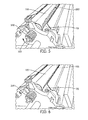
- Figs. 3 and 5 illustrate the developer roller 120 after the material 205 has been applied to the band 138.
- the material 205 may be applied to the band 138 without the additional step of removing the toner particles 134 because the mere addition of the material 205 is sufficient to reduce print defects.
- the developer roller 120 is back driven, i.e., rotated in a direction opposite the direction associated with normal operation of the cartridge, to position the material 205 between the developer roller 120 and the metering blade 115.
- the cartridge 100 includes a driving gear 300 that may be rotated in the direction illustrated by arrow 305 in Figs. 4 and 5 to back drive the developer roller 120.
- the developer roller 120 may be back driven manually or with an appropriate tool by way of the driving gear 300, by way of other gears, driving members, or rotatable components that may be provided on the cartridge 100, or by direct engagement with the developer roller 120 itself.
- the developer roller 120 is rotated in the direction of the arrow 305 until the material 205 is moved to oppose the edge 132 of the metering blade 115, such that the material 205 is located between the edge 132 of the metering blade 115 and the developer roller 120.
- This also positions the band 138 such that a portion of the band 138 opposes the edge 132 of the metering blade 115.
- the remanufactured toner cartridge 100 may be packaged and stored for prolonged periods with a reduced likelihood of print defects caused by material sticking to the developer roller 120.
- the relatively small amount of material 205 is typically removed from the developer roller during the initial startup procedure of the printer and has little or no effect on subsequent printing operations.
- Fig. 7 is a flow-chart illustrating one exemplary process 400 for reducing image artifact in the toner cartridge 100.
- Other embodiments of the process 400 may include more or less steps, including steps discussed above.
- the toner cartridge 100 is operated (Step 405), for example by way of a post test, which positions toner particles 134 between the edge 132 of the metering blade 115 and the developer roller.
- the toner particles 134 are optionally removed from a portion of the developer roller 120 that is on the downstream side of the metering blade 115, such as band 138 (Step 410).
- Material 205 is applied to the portion of the developer roller 120 that is on the downstream side of the metering blade 115, such as the band 138, for example using a brush or swab (Step 415).
- the material 205 is positioned between the edge 132 of the metering blade 115 and the developer roller 120 (Step 420), for example by back-driving the developer roller 120 to position a portion of the band 138 in opposing relationship with the edge 132 of the metering blade.
- the invention may also be applied to newly manufactured toner cartridges.
- the invention provides, among other things, an improved remanufactured toner cartridge, an improved toner cartridge, and an improved method for reducing image artifacts in remanufactured or newly manufactured toner cartridges.
Abstract
Description
- The invention generally relates to remanufactured printer cartridges, such as toner cartridges, and a method of remanufacturing printer cartridges.
- Printing systems, such as high volume printing devices (e.g., network printers, photocopiers, etc.) typically use toner cartridges which store and transmit toner to an intended medium, such as paper. Once the toner has depleted, the used toner cartridge is removed from the printing system, and typically disposed of. Remanufacturing of used toner cartridges permits the toner cartridges to be reused rather than disposed of in landfills.
- Toner cartridges come in a variety of configurations. Although specific constructions vary among manufacturers and printers, many toner cartridges include components such as a toner hopper, a variety of toner-regulating blades, a developer roller, a primary charge roller, and an organic photo-conductor drum.
- To avoid discarding useful materials and to thereby reduce the environmental impact of printing operations, many toner cartridges may be remanufactured. Remanufacturing involves collecting used toner cartridges that, prior to their use, were brand new cartridges typically supplied by the manufacturer of the printer with which the cartridges are compatible. These cartridges are often referred to in the art as "OEM cartridges" because they are supplied by the original equipment manufacturer, i.e., the manufacturer of the printer and the compatible printer cartridge.
- Remanufacturing of toner cartridges typically includes, among other things, disassembling the toner cartridge, cleaning the toner cartridge, refilling the toner hopper with new toner, repairing or replacing worn or damaged components, and reassembling the toner cartridge. In many remanufacturing operations, toner and other components used in the remanufacturing process are sourced from suppliers other than those that supply the components of the OEM cartridge. Thus, a remanufactured cartridge is often a mix of previously used OEM cartridge components and new aftermarket components. As a result, when developing a remanufactured cartridge, substantial trial and error is often required before arriving at a combination of replacement components and toner that interact with the used OEM components in a way that provides acceptable print quality and page volume.
- In one embodiment, the invention provides a remanufactured toner cartridge including a toner hopper; a mass of toner stored within the toner hopper, the toner having a first formulation; a developer roller supported for rotation by the toner hopper, the developer roller having an outer surface and including a portion that faces into the toner hopper for gathering toner from the toner hopper; a metering blade including an edge facing the developer roller, a first side facing into the toner hopper, and a second side facing away from the toner hopper; and a material having a second formulation between the edge of the metering blade and the outer surface of the developer roller, the second formulation different from the first formulation.
- In another embodiment the invention provides a method of reducing an image artifact in a remanufactured toner cartridge. The method includes operating the remanufactured toner cartridge to transfer toner to a position between a developer roller and a metering blade of the remanufactured toner cartridge, the toner having a first formulation; and positioning a material having a second formulation different from the first formulation between the developer roller and the metering blade.
- Other aspects of the invention will become apparent by consideration of the detailed description and accompanying drawings.
-
-
Fig. 1 illustrates an exploded view of a toner cartridge according to one embodiment of the invention. -
Fig. 2 illustrates a cross-sectional view taken along A of the assembled toner cartridge ofFig. 1 . -
Fig. 3 illustrates a cross-sectional view taken along A of the assembled toner cartridge ofFig. 1 . -
Fig. 4 illustrates a cross-sectional view taken along A of the assembled toner cartridge ofFig. 1 . -
Fig. 5 illustrates a perspective view of the assembled toner cartridge ofFig. 1 . -
Fig. 6 illustrates a perspective view of the assembled toner cartridge ofFig. 1 . -
Fig. 7 illustrates a process of for reducing streaks or an image artifact of the toner cartridge ofFig. 1 . - Before any embodiments of the invention are explained in detail, it is to be understood that the invention is not limited in its application to the details of construction and the arrangement of components set forth in the following description or illustrated in the following drawings. The invention is capable of other embodiments and of being practiced or of being carried out in various ways.
-
Fig. 1 is an exploded view of atoner cartridge 100. Thetoner cartridge 100 is a consumable component used in a printing system (e.g., network printers, laser printers, photocopiers, etc.). Thetoner cartridge 100 stores and, in cooperation with components of a compatible printer, transfers toner to an intended medium (e.g., paper). Toner typically has a predetermined toner electrical potential, and is therefore attracted to elements or components having a different electrical potential. For example, toner may be attracted to components having a more negative, more positive, or opposite electrical potential relative to the toner electrical potential. Therefore, during printing, the toner can be transmitted via a series of progressively increasing, progressively decreasing, or opposite electrical potentials that "hand off" the toner from component to component. - The
toner cartridge 100 includes atoner hopper 105 for storing a mass of toner having a first formulation. In some embodiments, thetoner hopper 105 is provided with aseal 110. Theseal 110 prevents toner from spilling prior to installation into the printing system. In some embodiments, theseal 110 is a removable protective strip. - The
toner cartridge 100 of the illustrated embodiment is an "all-in-one" cartridge and further includes the following components or elements: a metering blade (e.g., a charge blade or doctor blade) 115; a developer roller (i.e., a magnetic roller or a developer unit) 120; an organic photo-conductor (OPC)drum 125; and a primary charge roller (PCR) 130. In other embodiments, thetoner cartridge 100 may include more or fewer components. For example, alternative embodiments of thecartridge 100 may be developer cartridges that do not include an OPC drum or a PCR. In such embodiments, the OPC drum and PCR may be part of the printer or may be provided as a separately removable drum unit. - During operation, toner is collected from the
toner hopper 105 by the rotatingdeveloper roller 120 and electrostatically transferred from thedeveloper roller 120 to theOPC drum 125. A laser system having a laser beam, located within the printing system, scans an electrostatic image onto theOPC drum 125 with the laser beam. In some printers, the electrostatic image produced by the laser corresponds to the image to be printed. In other printers, the laser forms an electrostatic image that is a negative of the image that is to be printed. Regardless of the specific configuration, toner carried by thedeveloper roller 120 is electrostatically attracted to the electrostatic image produced on theOPC drum 125 by the laser beam. TheOPC drum 125 then applies the toner, which is in a pattern corresponding to the desired image, onto the intended medium by direct contact or by further electrostatic transfer. The toner is then fused to the intended medium, typically by way of a heating element (e.g., a fuser). - The
toner cartridge 100 further includes awiper blade 135. Thewiper blade 135 remains in constant contact with the OPCdrum 125 and wipes residual toner (i.e., toner remaining on theOPC drum 125 after transfer to the intended medium) from theOPC drum 125. The wiped residual toner is collected by awaste bin 140. - In some embodiments, the
toner cartridge 100 further includes adrum shutter 145. Thedrum shutter 145 protects the OPCdrum 125 from physical damage and exposure to light when thetoner cartridge 100 is not installed in the printing system. - During remanufacturing, the
toner cartridge 100 is disassembled. The components of the disassembledtoner cartridge 100 are then cleaned and worn or damaged components are repaired or replaced. Thetoner hopper 105 is refilled with toner, and thetoner cartridge 100 is then reassembled - Often times after remanufacture of the
toner cartridge 100, thetoner cartridge 100 is operated one or more times before being sold to the end user. Operation of thetoner cartridge 100 may include testing of thetoner cartridge 100, such as but not limited to, post-testing thetoner cartridge 100 for quality control purposes. A post-test includes installing thetoner cartridge 100 in a printing system and using the printing system, along with the installedtoner cartridge 100, to print one or more test pages in order to confirm proper operation of theremanufactured cartridge 100. - In some embodiments, the
toner hopper 105 is provided with theseal 110 prior to post-testing. In such an embodiment, because thetoner hopper 105 is sealed, toner does not transfer from thetoner hopper 105 to thedeveloper roller 120 during the post-test. Rather, prior to post-testing, the toner is applied to thedeveloper roller 120. Thetoner cartridge 100 is then installed in a printing system and one or more test pages are printed in order to confirm proper operation of theremanufactured cartridge 100. In such an embodiment, theseal 110 is then removed before operation of thetoner cartridge 100 by the end user. - Referring also to
Fig. 2 themetering blade 115 includes anedge 132. Theedge 132 is sized and positioned to apply a constant pressure on a narrow band of thedeveloper roller 120 in order to form a uniformly thick layer oftoner particles 134 on thedeveloper roller 120. As toner passes between theedge 132 and the narrow band of thedeveloper roller 120, a gap between theedge 132 and thedeveloper roller 120 is created (the gap being approximately equal to the thickness of the layer of toner). As thedeveloper roller 120 rotates in the direction of the arrow A, toner passes through the gap between theedge 132 of themetering blade 115 and thedeveloper roller 120 and is arranged into a uniform layer oftoner particles 134 on the surface of thedeveloper roller 120 that is "downstream" of themetering blade 115. It should be appreciated that, for clarity of understanding, the drawings have been simplified to show a layer of toner that is a single toner particle thick. In reality the layer of toner is generally greater than the thickness of an individual toner particle. -
Fig. 2 is an example of a condition of thedeveloper roller 120 andmetering blade 115 after a post-test operation. Themetering blade 115 includes afirst side 150 facing toward thetoner hopper 105 and asecond side 155 facing away from thetoner hopper 105. After operation, anouter surface 136 of thedeveloper roller 120 includes aband 138 that is covered intoner particles 134. Theband 138 is outside thetoner hopper 105 and on thesecond side 155 of themetering blade 115.Toner particles 134 are also present between theedge 132 of themetering blade 115 and theouter surface 136 of thedeveloper roller 120. In some circumstances, if thesetoner particles 134 are maintained between theedge 132 of themetering blade 115 and thedeveloper roller 120, thetoner particles 134 can become strongly attached to theouter surface 136 of thedeveloper roller 120. These strongly attachedtoner particles 134 may result in image artifacts, typically in the form of horizontal lines, on pages printed using thetoner cartridge 100. One set of circumstances known to give rise to such image artifacts includes prolonged storage in the presence of high heat and humidity. - Referring also to
Figs. 3 through 5 , to reduce the occurrence of image artifacts, amaterial 205 having different physical characteristics than thetoner particles 134, e.g., a second formulation, may be placed between theedge 132 of themetering blade 115 and thedeveloper roller 120. In some embodiments, thematerial 205 may have a lower affinity or adhesion tendency with respect to thedeveloper roller 120. Placing thematerial 205 between theedge 132 of themetering blade 115 and thedeveloper roller 120 may reduce the occurrence of image artifacts associated withtoner particles 134 sticking to thedeveloper roller 120. In the illustrated embodiment, thetoner particles 134 between theedge 132 of themetering blade 115 and thedeveloper roller 120 are removed before placement of the material. In other embodiments, thetoner particles 134 between theedge 132 of themetering blade 115 and thedeveloper roller 120 are not removed before placement of the material - In some embodiments, the
material 205 is a second toner having a substantially yellow color. The second toner may be an original equipment manufacturer toner having a substantially yellow color or another color. In some embodiments, the second toner may be mixed with a cyan, magenta, and/or black toner. In other embodiments, thematerial 205 includes a fluoroadditive, such as but not limited to, Zonyl® MP 1300. In other embodiments, thematerial 205 includes a silicone resin, such as but not limited to, a fine particle silicone resin. In some embodiments, the fine particle silicone resin includes a tospearl 3120 silicone resin. In still other embodiments, thematerial 205 may be a combination of two or more of the above materials. In another embodiment, thematerial 205 is a thin flexible material, such as but not limited to, ribbon or ribbon-like material that is removed before operation of thetoner cartridge 100 by the end user. - With reference to
Figs. 3-5 , following a post-test,toner particles 134 may be removed from theband 138, for example by wiping, and thematerial 205 may be applied to theband 138, for example using a brush or swab.Figs. 3 and5 illustrate thedeveloper roller 120 after thematerial 205 has been applied to theband 138. In some embodiments, thematerial 205 may be applied to theband 138 without the additional step of removing thetoner particles 134 because the mere addition of thematerial 205 is sufficient to reduce print defects. Once thematerial 205 has been applied to thedeveloper roller 120, thedeveloper roller 120 is back driven, i.e., rotated in a direction opposite the direction associated with normal operation of the cartridge, to position thematerial 205 between thedeveloper roller 120 and themetering blade 115. In the illustrated embodiment, thecartridge 100 includes adriving gear 300 that may be rotated in the direction illustrated byarrow 305 inFigs. 4 and5 to back drive thedeveloper roller 120. Thedeveloper roller 120 may be back driven manually or with an appropriate tool by way of thedriving gear 300, by way of other gears, driving members, or rotatable components that may be provided on thecartridge 100, or by direct engagement with thedeveloper roller 120 itself. - As illustrated in
Figs. 4 and6 , thedeveloper roller 120 is rotated in the direction of thearrow 305 until thematerial 205 is moved to oppose theedge 132 of themetering blade 115, such that thematerial 205 is located between theedge 132 of themetering blade 115 and thedeveloper roller 120. This also positions theband 138 such that a portion of theband 138 opposes theedge 132 of themetering blade 115. With thematerial 205 positioned between theedge 132 of themetering blade 115 and theouter surface 136 of thedeveloper roller 120, theremanufactured toner cartridge 100 may be packaged and stored for prolonged periods with a reduced likelihood of print defects caused by material sticking to thedeveloper roller 120. Upon use by the end user, the relatively small amount ofmaterial 205 is typically removed from the developer roller during the initial startup procedure of the printer and has little or no effect on subsequent printing operations. -
Fig. 7 is a flow-chart illustrating oneexemplary process 400 for reducing image artifact in thetoner cartridge 100. Other embodiments of theprocess 400 may include more or less steps, including steps discussed above. Thetoner cartridge 100 is operated (Step 405), for example by way of a post test, which positionstoner particles 134 between theedge 132 of themetering blade 115 and the developer roller. Thetoner particles 134 are optionally removed from a portion of thedeveloper roller 120 that is on the downstream side of themetering blade 115, such as band 138 (Step 410).Material 205 is applied to the portion of thedeveloper roller 120 that is on the downstream side of themetering blade 115, such as theband 138, for example using a brush or swab (Step 415). Thematerial 205 is positioned between theedge 132 of themetering blade 115 and the developer roller 120 (Step 420), for example by back-driving thedeveloper roller 120 to position a portion of theband 138 in opposing relationship with theedge 132 of the metering blade. - Although the foregoing description refers to remanufactured
toner cartridges 100, the invention may also be applied to newly manufactured toner cartridges. Thus, the invention provides, among other things, an improved remanufactured toner cartridge, an improved toner cartridge, and an improved method for reducing image artifacts in remanufactured or newly manufactured toner cartridges. Various features and advantages of the invention are set forth in the following claims.
Claims (22)
- A method of reducing an image artifact in a remanufactured toner cartridge, the method comprising:operating the remanufactured toner cartridge to transfer toner to a position between a developer roller and a metering blade of the remanufactured toner cartridge, the toner having a first formulation; andpositioning a material having a second formulation different from the first formulation between the developer roller and the metering blade.
- The method of claim 1, wherein positioning the material between the developer roller and the metering blade includes replacing the toner with the material.
- The method of claim 1, wherein the material includes a toner having a substantially yellow color.
- The method of claim 1, wherein the material includes a fluoroadditive.
- The method of claim 1, wherein the material includes a silicone resin.
- The method of claim 1, wherein positioning the material between the developer roller and the metering blade includes back-driving the developer roller.
- The method of claim 1, wherein positioning the material between the developer roller and the metering blade includes, after operating the remanufactured toner cartridge, applying the material to a portion of the developer roller that is outside a toner hopper and on a first side of the metering blade.
- The method of claim 7, wherein positioning the material between the developer roller and the metering blade further includes back-driving the developer roller such that the portion of the developer roller with the material applied is moved to oppose an edge of the metering blade, the edge of the metering blade facing towards the developer roller.
- The method of claim 7, wherein positioning the material between the developer roller and the metering blade further includes removing toner from the portion of the developer roller before applying the material to the portion of the developer roller.
- The method of claim 7, wherein the toner comprises a first toner, and wherein the material comprises a second toner.
- The method of claim 1, wherein the toner comprises an aftermarket toner and the material comprises an original equipment manufacturer toner.
- The method of claim 1, wherein operating the remanufactured toner cartridge includes post testing the remanufactured toner cartridge.
- A remanufactured toner cartridge comprising:a toner hopper;a mass of toner stored within the toner hopper, the toner having a first formulation;a developer roller supported for rotation by the toner hopper, the developer roller having an outer surface and including a portion that faces into the toner hopper for gathering toner from the toner hopper;a metering blade including an edge facing the developer roller, a first side facing into the toner hopper, and a second side facing away from the toner hopper; anda material having a second formulation between the edge of the metering blade and the outer surface of the developer roller, the second formulation being different from the first formulation.
- The toner cartridge of claim 13, wherein the material includes a toner having a substantially yellow color.
- The toner cartridge of claim 13, wherein the material includes a fluroadditive.
- The toner cartridge of claim 13, wherein the material includes a silicone resin.
- The toner cartridge of claim 13, wherein the mass of toner stored within the toner hopper comprises a first toner, and wherein the material comprises a second toner.
- The toner cartridge of claim 13, wherein the toner comprises an aftermarket toner and the material comprises an original equipment manufacturer toner.
- The toner cartridge of claim 13, wherein the material comprises an original equipment manufacturer yellow toner.
- The toner cartridge of claim 13, wherein the outer surface of the developer roller includes a band that is outside the toner hopper and on the second side of the metering blade upon completion of an operation of the toner cartridge, and wherein upon completion of the operation a portion of the band faces the edge of the metering blade.
- The toner cartridge of claim 20, wherein the material is located between the edge of the metering blade and the portion of the band.
- The toner cartridge of claim 20, wherein the operation of the toner cartridge includes post testing the toner cartridge.
Applications Claiming Priority (1)
| Application Number | Priority Date | Filing Date | Title |
|---|---|---|---|
| US14/275,185 US9223251B2 (en) | 2014-05-12 | 2014-05-12 | Toner cartridge and method for reducing image artifact |
Publications (2)
| Publication Number | Publication Date |
|---|---|
| EP2945021A1 true EP2945021A1 (en) | 2015-11-18 |
| EP2945021B1 EP2945021B1 (en) | 2021-04-14 |
Family
ID=53051748
Family Applications (1)
| Application Number | Title | Priority Date | Filing Date |
|---|---|---|---|
| EP15166928.0A Active EP2945021B1 (en) | 2014-05-12 | 2015-05-08 | Toner cartridge and method for reducing image artifact |
Country Status (2)
| Country | Link |
|---|---|
| US (1) | US9223251B2 (en) |
| EP (1) | EP2945021B1 (en) |
Cited By (2)
| Publication number | Priority date | Publication date | Assignee | Title |
|---|---|---|---|---|
| WO2017196846A1 (en) * | 2016-05-10 | 2017-11-16 | Clover Technologies Group, Llc | Remanufactured toner cartridge and test method therefor |
| US10514632B2 (en) | 2016-05-18 | 2019-12-24 | Clover Technologies Group, Llc | Method of remanufacturing a toner cartridge |
Citations (4)
| Publication number | Priority date | Publication date | Assignee | Title |
|---|---|---|---|---|
| EP1217468A2 (en) * | 2000-12-20 | 2002-06-26 | Canon Kabushiki Kaisha | Remanufacturing method for process cartridge |
| US20040247346A1 (en) * | 2003-01-31 | 2004-12-09 | Canon Kabushiki Kaisha | Developing apparatus and image forming apparatus |
| EP2230561A1 (en) * | 2009-03-20 | 2010-09-22 | Wazana Brothers International, Inc., d/b/a Micro Solutions Enterprises | Method and composition for recoating toner cartridge developing member |
| US20120301189A1 (en) * | 2011-05-25 | 2012-11-29 | Canon Kabushiki Kaisha | Regulating member, developing device and process cartridge |
Family Cites Families (3)
| Publication number | Priority date | Publication date | Assignee | Title |
|---|---|---|---|---|
| EP0778506A1 (en) | 1995-12-05 | 1997-06-11 | Brother Kogyo Kabushiki Kaisha | Electrophotographic type image forming device and developing roller for use in the device |
| JP2012073323A (en) * | 2010-09-28 | 2012-04-12 | Konica Minolta Business Technologies Inc | Organic photoreceptor and image forming apparatus |
| US20130287451A1 (en) * | 2012-04-26 | 2013-10-31 | Canon Kabushiki Kaisha | Image forming apparatus, developing apparatus, and process cartridge |
-
2014
- 2014-05-12 US US14/275,185 patent/US9223251B2/en active Active
-
2015
- 2015-05-08 EP EP15166928.0A patent/EP2945021B1/en active Active
Patent Citations (4)
| Publication number | Priority date | Publication date | Assignee | Title |
|---|---|---|---|---|
| EP1217468A2 (en) * | 2000-12-20 | 2002-06-26 | Canon Kabushiki Kaisha | Remanufacturing method for process cartridge |
| US20040247346A1 (en) * | 2003-01-31 | 2004-12-09 | Canon Kabushiki Kaisha | Developing apparatus and image forming apparatus |
| EP2230561A1 (en) * | 2009-03-20 | 2010-09-22 | Wazana Brothers International, Inc., d/b/a Micro Solutions Enterprises | Method and composition for recoating toner cartridge developing member |
| US20120301189A1 (en) * | 2011-05-25 | 2012-11-29 | Canon Kabushiki Kaisha | Regulating member, developing device and process cartridge |
Cited By (7)
| Publication number | Priority date | Publication date | Assignee | Title |
|---|---|---|---|---|
| WO2017196846A1 (en) * | 2016-05-10 | 2017-11-16 | Clover Technologies Group, Llc | Remanufactured toner cartridge and test method therefor |
| CN109478033A (en) * | 2016-05-10 | 2019-03-15 | 克罗弗科技集团有限责任公司 | The toner Cartridge and method remanufactured |
| US10303087B2 (en) | 2016-05-10 | 2019-05-28 | Clover Technologies Group, Llc | Remanufactured toner cartridge and method |
| US10452000B2 (en) | 2016-05-10 | 2019-10-22 | Clover Technologies Group, Llc | Remanufactured toner cartridge and method |
| CN109478033B (en) * | 2016-05-10 | 2021-12-03 | 克罗弗影像集团有限责任公司 | Remanufactured toner cartridge and method |
| US10514632B2 (en) | 2016-05-18 | 2019-12-24 | Clover Technologies Group, Llc | Method of remanufacturing a toner cartridge |
| US11016418B2 (en) | 2016-05-18 | 2021-05-25 | Clover Imaging Group, Llc | Method of remanufacturing a toner cartridge |
Also Published As
| Publication number | Publication date |
|---|---|
| EP2945021B1 (en) | 2021-04-14 |
| US20150323887A1 (en) | 2015-11-12 |
| US9223251B2 (en) | 2015-12-29 |
Similar Documents
| Publication | Publication Date | Title |
|---|---|---|
| JP2010091852A (en) | Lubricant application device and image forming apparatus | |
| US10599071B2 (en) | Toner cartridge and method of sealing the same | |
| EP2945021B1 (en) | Toner cartridge and method for reducing image artifact | |
| US7945200B2 (en) | Systems and methods for remanufacturing imaging components | |
| JP4750522B2 (en) | Developing device and image forming apparatus | |
| US20150153683A1 (en) | Remanufactured Toner Cartridge with Added Cleaning Roller for the Primary Charge Roller, and Methods | |
| EP3488296B1 (en) | Operating a liquid electrophotographic printer | |
| US20050152714A1 (en) | Preventing printer toner leakage | |
| JP4961226B2 (en) | Photoconductor cleaning device and image forming apparatus | |
| US11740568B2 (en) | Reducing reflectance variances of photoconductive surfaces | |
| EP3516458B1 (en) | System and method of remanufacturing a toner container | |
| US8467699B2 (en) | Remanufactured toner cartridge with added primary charge roller cleaner, and methods | |
| US7970319B2 (en) | Charging apparatus, print engine that incorporates the charging apparatus, and image forming apparatus that incorporates the print engine | |
| JP6604190B2 (en) | Process unit and drum cartridge | |
| JP5797109B2 (en) | Developing device and image forming apparatus | |
| JP5333687B2 (en) | Lubricant coating apparatus and image forming apparatus | |
| JP2010032909A (en) | Image forming device | |
| US20090245885A1 (en) | Developing device and image forming apparatus | |
| JP2013033147A (en) | Cleaning device and image forming apparatus using the same | |
| JP2013156418A (en) | Image forming apparatus | |
| JP2009025606A (en) | Image forming apparatus | |
| JP2009025605A (en) | Image forming apparatus | |
| JP2017083688A (en) | Image formation apparatus | |
| JP2002072695A (en) | Liquid coating unit, liquid developing unit and image forming apparatus | |
| JPH11316519A (en) | Method and device for displaying time to exchange photoreceptor drum for electrophotographic printer |
Legal Events
| Date | Code | Title | Description |
|---|---|---|---|
| PUAI | Public reference made under article 153(3) epc to a published international application that has entered the european phase |
Free format text: ORIGINAL CODE: 0009012 |
|
| AK | Designated contracting states |
Kind code of ref document: A1 Designated state(s): AL AT BE BG CH CY CZ DE DK EE ES FI FR GB GR HR HU IE IS IT LI LT LU LV MC MK MT NL NO PL PT RO RS SE SI SK SM TR |
|
| AX | Request for extension of the european patent |
Extension state: BA ME |
|
| 17P | Request for examination filed |
Effective date: 20160517 |
|
| RBV | Designated contracting states (corrected) |
Designated state(s): AL AT BE BG CH CY CZ DE DK EE ES FI FR GB GR HR HU IE IS IT LI LT LU LV MC MK MT NL NO PL PT RO RS SE SI SK SM TR |
|
| RAP1 | Party data changed (applicant data changed or rights of an application transferred) |
Owner name: CLOVER IMAGING GROUP, LLC |
|
| GRAP | Despatch of communication of intention to grant a patent |
Free format text: ORIGINAL CODE: EPIDOSNIGR1 |
|
| STAA | Information on the status of an ep patent application or granted ep patent |
Free format text: STATUS: GRANT OF PATENT IS INTENDED |
|
| INTG | Intention to grant announced |
Effective date: 20201126 |
|
| GRAS | Grant fee paid |
Free format text: ORIGINAL CODE: EPIDOSNIGR3 |
|
| GRAA | (expected) grant |
Free format text: ORIGINAL CODE: 0009210 |
|
| STAA | Information on the status of an ep patent application or granted ep patent |
Free format text: STATUS: THE PATENT HAS BEEN GRANTED |
|
| AK | Designated contracting states |
Kind code of ref document: B1 Designated state(s): AL AT BE BG CH CY CZ DE DK EE ES FI FR GB GR HR HU IE IS IT LI LT LU LV MC MK MT NL NO PL PT RO RS SE SI SK SM TR |
|
| REG | Reference to a national code |
Ref country code: GB Ref legal event code: FG4D |
|
| REG | Reference to a national code |
Ref country code: CH Ref legal event code: EP |
|
| REG | Reference to a national code |
Ref country code: DE Ref legal event code: R096 Ref document number: 602015068020 Country of ref document: DE |
|
| REG | Reference to a national code |
Ref country code: IE Ref legal event code: FG4D |
|
| REG | Reference to a national code |
Ref country code: AT Ref legal event code: REF Ref document number: 1382975 Country of ref document: AT Kind code of ref document: T Effective date: 20210515 |
|
| REG | Reference to a national code |
Ref country code: LT Ref legal event code: MG9D |
|
| REG | Reference to a national code |
Ref country code: AT Ref legal event code: MK05 Ref document number: 1382975 Country of ref document: AT Kind code of ref document: T Effective date: 20210414 |
|
| REG | Reference to a national code |
Ref country code: NL Ref legal event code: MP Effective date: 20210414 |
|
| PG25 | Lapsed in a contracting state [announced via postgrant information from national office to epo] |
Ref country code: HR Free format text: LAPSE BECAUSE OF FAILURE TO SUBMIT A TRANSLATION OF THE DESCRIPTION OR TO PAY THE FEE WITHIN THE PRESCRIBED TIME-LIMIT Effective date: 20210414 Ref country code: FI Free format text: LAPSE BECAUSE OF FAILURE TO SUBMIT A TRANSLATION OF THE DESCRIPTION OR TO PAY THE FEE WITHIN THE PRESCRIBED TIME-LIMIT Effective date: 20210414 Ref country code: NL Free format text: LAPSE BECAUSE OF FAILURE TO SUBMIT A TRANSLATION OF THE DESCRIPTION OR TO PAY THE FEE WITHIN THE PRESCRIBED TIME-LIMIT Effective date: 20210414 Ref country code: LT Free format text: LAPSE BECAUSE OF FAILURE TO SUBMIT A TRANSLATION OF THE DESCRIPTION OR TO PAY THE FEE WITHIN THE PRESCRIBED TIME-LIMIT Effective date: 20210414 Ref country code: BG Free format text: LAPSE BECAUSE OF FAILURE TO SUBMIT A TRANSLATION OF THE DESCRIPTION OR TO PAY THE FEE WITHIN THE PRESCRIBED TIME-LIMIT Effective date: 20210714 Ref country code: AT Free format text: LAPSE BECAUSE OF FAILURE TO SUBMIT A TRANSLATION OF THE DESCRIPTION OR TO PAY THE FEE WITHIN THE PRESCRIBED TIME-LIMIT Effective date: 20210414 |
|
| PG25 | Lapsed in a contracting state [announced via postgrant information from national office to epo] |
Ref country code: IS Free format text: LAPSE BECAUSE OF FAILURE TO SUBMIT A TRANSLATION OF THE DESCRIPTION OR TO PAY THE FEE WITHIN THE PRESCRIBED TIME-LIMIT Effective date: 20210814 Ref country code: LV Free format text: LAPSE BECAUSE OF FAILURE TO SUBMIT A TRANSLATION OF THE DESCRIPTION OR TO PAY THE FEE WITHIN THE PRESCRIBED TIME-LIMIT Effective date: 20210414 Ref country code: GR Free format text: LAPSE BECAUSE OF FAILURE TO SUBMIT A TRANSLATION OF THE DESCRIPTION OR TO PAY THE FEE WITHIN THE PRESCRIBED TIME-LIMIT Effective date: 20210715 Ref country code: SE Free format text: LAPSE BECAUSE OF FAILURE TO SUBMIT A TRANSLATION OF THE DESCRIPTION OR TO PAY THE FEE WITHIN THE PRESCRIBED TIME-LIMIT Effective date: 20210414 Ref country code: RS Free format text: LAPSE BECAUSE OF FAILURE TO SUBMIT A TRANSLATION OF THE DESCRIPTION OR TO PAY THE FEE WITHIN THE PRESCRIBED TIME-LIMIT Effective date: 20210414 Ref country code: PT Free format text: LAPSE BECAUSE OF FAILURE TO SUBMIT A TRANSLATION OF THE DESCRIPTION OR TO PAY THE FEE WITHIN THE PRESCRIBED TIME-LIMIT Effective date: 20210816 Ref country code: NO Free format text: LAPSE BECAUSE OF FAILURE TO SUBMIT A TRANSLATION OF THE DESCRIPTION OR TO PAY THE FEE WITHIN THE PRESCRIBED TIME-LIMIT Effective date: 20210714 Ref country code: PL Free format text: LAPSE BECAUSE OF FAILURE TO SUBMIT A TRANSLATION OF THE DESCRIPTION OR TO PAY THE FEE WITHIN THE PRESCRIBED TIME-LIMIT Effective date: 20210414 Ref country code: ES Free format text: LAPSE BECAUSE OF FAILURE TO SUBMIT A TRANSLATION OF THE DESCRIPTION OR TO PAY THE FEE WITHIN THE PRESCRIBED TIME-LIMIT Effective date: 20210414 |
|
| REG | Reference to a national code |
Ref country code: CH Ref legal event code: PL |
|
| REG | Reference to a national code |
Ref country code: DE Ref legal event code: R097 Ref document number: 602015068020 Country of ref document: DE |
|
| PG25 | Lapsed in a contracting state [announced via postgrant information from national office to epo] |
Ref country code: SM Free format text: LAPSE BECAUSE OF FAILURE TO SUBMIT A TRANSLATION OF THE DESCRIPTION OR TO PAY THE FEE WITHIN THE PRESCRIBED TIME-LIMIT Effective date: 20210414 Ref country code: SK Free format text: LAPSE BECAUSE OF FAILURE TO SUBMIT A TRANSLATION OF THE DESCRIPTION OR TO PAY THE FEE WITHIN THE PRESCRIBED TIME-LIMIT Effective date: 20210414 Ref country code: EE Free format text: LAPSE BECAUSE OF FAILURE TO SUBMIT A TRANSLATION OF THE DESCRIPTION OR TO PAY THE FEE WITHIN THE PRESCRIBED TIME-LIMIT Effective date: 20210414 Ref country code: CZ Free format text: LAPSE BECAUSE OF FAILURE TO SUBMIT A TRANSLATION OF THE DESCRIPTION OR TO PAY THE FEE WITHIN THE PRESCRIBED TIME-LIMIT Effective date: 20210414 Ref country code: DK Free format text: LAPSE BECAUSE OF FAILURE TO SUBMIT A TRANSLATION OF THE DESCRIPTION OR TO PAY THE FEE WITHIN THE PRESCRIBED TIME-LIMIT Effective date: 20210414 Ref country code: RO Free format text: LAPSE BECAUSE OF FAILURE TO SUBMIT A TRANSLATION OF THE DESCRIPTION OR TO PAY THE FEE WITHIN THE PRESCRIBED TIME-LIMIT Effective date: 20210414 Ref country code: CH Free format text: LAPSE BECAUSE OF NON-PAYMENT OF DUE FEES Effective date: 20210531 Ref country code: LU Free format text: LAPSE BECAUSE OF NON-PAYMENT OF DUE FEES Effective date: 20210508 Ref country code: MC Free format text: LAPSE BECAUSE OF FAILURE TO SUBMIT A TRANSLATION OF THE DESCRIPTION OR TO PAY THE FEE WITHIN THE PRESCRIBED TIME-LIMIT Effective date: 20210414 Ref country code: LI Free format text: LAPSE BECAUSE OF NON-PAYMENT OF DUE FEES Effective date: 20210531 |
|
| REG | Reference to a national code |
Ref country code: BE Ref legal event code: MM Effective date: 20210531 |
|
| PLBE | No opposition filed within time limit |
Free format text: ORIGINAL CODE: 0009261 |
|
| STAA | Information on the status of an ep patent application or granted ep patent |
Free format text: STATUS: NO OPPOSITION FILED WITHIN TIME LIMIT |
|
| 26N | No opposition filed |
Effective date: 20220117 |
|
| PG25 | Lapsed in a contracting state [announced via postgrant information from national office to epo] |
Ref country code: IE Free format text: LAPSE BECAUSE OF NON-PAYMENT OF DUE FEES Effective date: 20210508 |
|
| PG25 | Lapsed in a contracting state [announced via postgrant information from national office to epo] |
Ref country code: IS Free format text: LAPSE BECAUSE OF FAILURE TO SUBMIT A TRANSLATION OF THE DESCRIPTION OR TO PAY THE FEE WITHIN THE PRESCRIBED TIME-LIMIT Effective date: 20210814 Ref country code: AL Free format text: LAPSE BECAUSE OF FAILURE TO SUBMIT A TRANSLATION OF THE DESCRIPTION OR TO PAY THE FEE WITHIN THE PRESCRIBED TIME-LIMIT Effective date: 20210414 |
|
| PG25 | Lapsed in a contracting state [announced via postgrant information from national office to epo] |
Ref country code: IT Free format text: LAPSE BECAUSE OF FAILURE TO SUBMIT A TRANSLATION OF THE DESCRIPTION OR TO PAY THE FEE WITHIN THE PRESCRIBED TIME-LIMIT Effective date: 20210414 Ref country code: BE Free format text: LAPSE BECAUSE OF NON-PAYMENT OF DUE FEES Effective date: 20210531 |
|
| PGFP | Annual fee paid to national office [announced via postgrant information from national office to epo] |
Ref country code: GB Payment date: 20220520 Year of fee payment: 8 Ref country code: FR Payment date: 20220524 Year of fee payment: 8 Ref country code: DE Payment date: 20220519 Year of fee payment: 8 |
|
| PG25 | Lapsed in a contracting state [announced via postgrant information from national office to epo] |
Ref country code: HU Free format text: LAPSE BECAUSE OF FAILURE TO SUBMIT A TRANSLATION OF THE DESCRIPTION OR TO PAY THE FEE WITHIN THE PRESCRIBED TIME-LIMIT; INVALID AB INITIO Effective date: 20150508 |
|
| PG25 | Lapsed in a contracting state [announced via postgrant information from national office to epo] |
Ref country code: CY Free format text: LAPSE BECAUSE OF FAILURE TO SUBMIT A TRANSLATION OF THE DESCRIPTION OR TO PAY THE FEE WITHIN THE PRESCRIBED TIME-LIMIT Effective date: 20210414 |
|
| REG | Reference to a national code |
Ref country code: DE Ref legal event code: R119 Ref document number: 602015068020 Country of ref document: DE |
|
| GBPC | Gb: european patent ceased through non-payment of renewal fee |
Effective date: 20230508 |