EP2944985B1 - Reflection light grid - Google Patents
Reflection light grid Download PDFInfo
- Publication number
- EP2944985B1 EP2944985B1 EP14167874.8A EP14167874A EP2944985B1 EP 2944985 B1 EP2944985 B1 EP 2944985B1 EP 14167874 A EP14167874 A EP 14167874A EP 2944985 B1 EP2944985 B1 EP 2944985B1
- Authority
- EP
- European Patent Office
- Prior art keywords
- light
- polarization
- reflector
- polarization direction
- filter
- Prior art date
- Legal status (The legal status is an assumption and is not a legal conclusion. Google has not performed a legal analysis and makes no representation as to the accuracy of the status listed.)
- Active
Links
Images


Classifications
-
- G—PHYSICS
- G01—MEASURING; TESTING
- G01V—GEOPHYSICS; GRAVITATIONAL MEASUREMENTS; DETECTING MASSES OR OBJECTS; TAGS
- G01V8/00—Prospecting or detecting by optical means
- G01V8/10—Detecting, e.g. by using light barriers
- G01V8/20—Detecting, e.g. by using light barriers using multiple transmitters or receivers
- G01V8/22—Detecting, e.g. by using light barriers using multiple transmitters or receivers using reflectors
-
- F—MECHANICAL ENGINEERING; LIGHTING; HEATING; WEAPONS; BLASTING
- F16—ENGINEERING ELEMENTS AND UNITS; GENERAL MEASURES FOR PRODUCING AND MAINTAINING EFFECTIVE FUNCTIONING OF MACHINES OR INSTALLATIONS; THERMAL INSULATION IN GENERAL
- F16P—SAFETY DEVICES IN GENERAL; SAFETY DEVICES FOR PRESSES
- F16P3/00—Safety devices acting in conjunction with the control or operation of a machine; Control arrangements requiring the simultaneous use of two or more parts of the body
- F16P3/12—Safety devices acting in conjunction with the control or operation of a machine; Control arrangements requiring the simultaneous use of two or more parts of the body with means, e.g. feelers, which in case of the presence of a body part of a person in or near the danger zone influence the control or operation of the machine
- F16P3/14—Safety devices acting in conjunction with the control or operation of a machine; Control arrangements requiring the simultaneous use of two or more parts of the body with means, e.g. feelers, which in case of the presence of a body part of a person in or near the danger zone influence the control or operation of the machine the means being photocells or other devices sensitive without mechanical contact
- F16P3/144—Safety devices acting in conjunction with the control or operation of a machine; Control arrangements requiring the simultaneous use of two or more parts of the body with means, e.g. feelers, which in case of the presence of a body part of a person in or near the danger zone influence the control or operation of the machine the means being photocells or other devices sensitive without mechanical contact using light grids
-
- G—PHYSICS
- G01—MEASURING; TESTING
- G01S—RADIO DIRECTION-FINDING; RADIO NAVIGATION; DETERMINING DISTANCE OR VELOCITY BY USE OF RADIO WAVES; LOCATING OR PRESENCE-DETECTING BY USE OF THE REFLECTION OR RERADIATION OF RADIO WAVES; ANALOGOUS ARRANGEMENTS USING OTHER WAVES
- G01S17/00—Systems using the reflection or reradiation of electromagnetic waves other than radio waves, e.g. lidar systems
- G01S17/02—Systems using the reflection of electromagnetic waves other than radio waves
- G01S17/04—Systems determining the presence of a target
-
- G—PHYSICS
- G01—MEASURING; TESTING
- G01S—RADIO DIRECTION-FINDING; RADIO NAVIGATION; DETERMINING DISTANCE OR VELOCITY BY USE OF RADIO WAVES; LOCATING OR PRESENCE-DETECTING BY USE OF THE REFLECTION OR RERADIATION OF RADIO WAVES; ANALOGOUS ARRANGEMENTS USING OTHER WAVES
- G01S17/00—Systems using the reflection or reradiation of electromagnetic waves other than radio waves, e.g. lidar systems
- G01S17/87—Combinations of systems using electromagnetic waves other than radio waves
-
- G—PHYSICS
- G01—MEASURING; TESTING
- G01S—RADIO DIRECTION-FINDING; RADIO NAVIGATION; DETERMINING DISTANCE OR VELOCITY BY USE OF RADIO WAVES; LOCATING OR PRESENCE-DETECTING BY USE OF THE REFLECTION OR RERADIATION OF RADIO WAVES; ANALOGOUS ARRANGEMENTS USING OTHER WAVES
- G01S7/00—Details of systems according to groups G01S13/00, G01S15/00, G01S17/00
- G01S7/48—Details of systems according to groups G01S13/00, G01S15/00, G01S17/00 of systems according to group G01S17/00
- G01S7/499—Details of systems according to groups G01S13/00, G01S15/00, G01S17/00 of systems according to group G01S17/00 using polarisation effects
Definitions
- the present invention relates to a reflective light grid having a plurality of light emitters and a plurality of light receivers in a housing and an opposed retroreflective reflector that reflects incoming light rays nearly parallel to their direction of incidence, the retroreflective reflector having at least a first portion and having at least a second portion, wherein a first Light transmitter, a first light receiver and the first portion of the reflector form a reflection light barrier and form a second light emitter, a second light receiver and the second portion of the reflector, a second reflection light barrier.
- a relative squint angle between the light transmitters must be kept to a minimum, in order to ensure a sensor with sufficient measuring accuracy.
- a complete avoidance of the relative squint angle is not guaranteed due to component tolerances.
- the beam of a light emitter is divergent at a certain distance, i. H. The diameter of the light spot increases with increasing distance.
- a reflection light grating requires a reflector of appropriate length, so that all light emitter beams are reflected.
- the disadvantage here is that this reflects the complete light spot. Depending on the reflector distance and the beam divergence, this light spot becomes significantly larger than the transmitter lens. In addition, there is an offset of the light spot due to the squint angle. Since the complete light spot is reflected, the complete light spot must also be covered by the object to be detected. The accuracy and a minimum detectable object are therefore dependent when using a conventional reflector the size and position of the transmitter light spot on the reflector, or in the measuring field or monitoring field.
- the EP 2 317 347 A2 discloses an optical sensor for detecting objects in a surveillance area with a reflector, the reflector being at least partially made of fluorescent material.
- the U.S. 4,958,068 discloses a series of reflection light barriers with polarizing filters.
- the EP 2 502 098 A1 discloses a light curtain having an opposed reflector with polarizing filters to enable polarization-dependent object detection.
- the DE 199 24 470 A1 discloses a reflective light barrier with polarizing filters.
- the EP 2 192 423 A1 discloses a reflection light grid having a polarizing filter.
- An object of the invention is to provide a reflection light grid which is suitable for the measurement of objects and has a higher resolution.
- the light of a light emitter predominantly passes over a corresponding section of the reflector to the corresponding light receiver of the reflection light barrier.
- the light which reaches the adjacent sections of the reflector meets negligibly on the light receiver of the reflection light barrier.
- a transmission beam of the light transmitter has at the location of the reflector usually has a larger diameter than a portion of the reflector toward the adjacent next section. Due to the polarization-selective arrangement of light emitter, section of the reflector and light receiver mainly passes the light a section back to the appropriate recipient. The diameter of the beam is thus reduced to the extent of the portion of the reflector. Ie. although light is reflected by each section, the light is differently polarized so that differently polarized light reaches the different receivers, ie only the 'right' part of the light.
- any light transmitter squint angle which may be present is also compensated, since only the light beams striking the section of the reflector reach the corresponding receiver.
- the reflected light passes according to the reflection light grating according to the invention only from a defined portion of the reflector in the receiver, a minimum object size to be detected is smaller, and thus a better object detection is achieved. As a result, an improved accuracy in the measurement of objects is achieved.
- a resolution of the reflection light grating is improved, so that the best resolution is determined only by the size of the sections of the reflector and an adjustment of switching thresholds.
- the resolution is independent of the beam divergence and the squint angle.
- the light emitters are arranged directly adjacent in a row and the light receivers are arranged parallel to the light emitters directly adjacent in a row.
- Each light transmitter and each adjacent light receiver also forms a reflection light barrier.
- a resolution twice as high that is also a twice as fine sampling raster, is achieved.
- the light emitter and light receiver are each arranged in two rows, with light emitter and light receiver alternating in a row and each light emitter of one row is assigned a light receiver of the other row.
- Each light transmitter and each adjacent light receiver also forms a reflection light barrier.
- the first polarization direction of the first polarization filter and the polarization direction of the second polarization filter differ by 45 °.
- the third polarization direction of the third polarization filter and the fourth polarization direction of the fourth polarization filter differ by 45 °.
- the first polarization direction of the first polarization filter and the third polarization direction of the third polarization filter differ by 90 °.
- the second polarization direction of the second polarization filter and the fourth polarization direction of the fourth polarization filter differ by 90 °.
- the reflector has triple mirrors made of plane mirror surfaces, which are each arranged at 90 ° to one another, so that the reflector, depending on the orientation, rotates the polarization direction of reflected light with respect to the incident light by 90 °.
- the first portion of the reflector is rotated such that a maximum of light from the first light emitter reaches the first receiver and the second portion of the reflector is rotated such that maximum amount of light from the second light emitter to the second receiver passes, wherein the angle of rotation of the first portion of the reflector and the second portion of the reflector differ by 45 °.
- the first polarization direction of the first polarization filter and the polarization direction of the second polarization filter differ by 90 °.
- the third polarization direction of the third polarization filter and the fourth polarization direction of the fourth polarization filter differ by 90 °.
- the first polarization direction of the first polarization filter and the third polarization direction of the third polarization filter do not differ and the second polarization direction of the second polarization filter and the fourth polarization direction of the fourth polarization filter do not differ.
- the reflector has a lens-like structure, so that the reflected light has the same direction of polarization as the incident light, wherein before the first portion of the reflector, a fifth polarizing filter is arranged with a fifth polarization direction and before the second portion of the reflector, a sixth polarization filter a sixth polarization direction is arranged, wherein the fifth polarization direction of the fifth polarization filter and the sixth polarization direction of the sixth polarization filter differ by 90 °.
- a polarization filter is now arranged in front of each section of the reflector, so that the light of an associated light transmitter passes via the associated portion of the reflector to the associated light receiver.
- the light transmitters and / or the light receivers have optics.
- the optic is preferably arranged between light transmitter or light receiver and polarization filter.
- the optics determine the beam divergence.
- the optics are formed in the simplest case by a diaphragm. However, the optics may also be formed by a lens or a lens system.
- the beam divergence is set, for example, at an angle of 0 °, ie parallel light beams up to approximately +/- 5 °.
- a squint angle refers to the deviation of the light axis of the light emitter from the desired direction. In the ideal case, all light axes of the light emitters are aligned in parallel.
- the polarization filters are linear polarization filters.
- Linear polarizing filters are easy to manufacture and therefore inexpensive.
- the linear polarizing filters need only be arranged for the desired effect in a specific orientation, that is to say in a specific polarization direction.
- two adjacent reflection light barriers can be optically separated without mutual interference taking place.
- the polarization filters are circular polarization filters. Circular polarizing filters are formed by a linear polarizing filter and a ⁇ / 4 foil.
- the transmitted light of a light transmitter meets only a maximum of three opposite sections of the reflector. This is achieved by a suitable choice of the beam divergence of the light emitter and by the distance between the light emitters or light receivers and the reflector and the distances of the light emitter to each other. The squint angle and the beam divergence together define the maximum distance of the reflector. The smaller the beam divergence of the light emitter and the farther the distances between the light emitters, the greater the distance between the light emitter or light receiver and the reflector. However, the higher the measurement resolution of the reflection light grating is desired, the smaller the distances between the light emitters or between the light receivers must be.
- the light of different light transmitters has different wavelengths and the associated light receivers are sensitive only to this wavelength. This makes it possible to optically decouple an even larger number of reflection light barriers. For example, two light transmitters with identical polarization direction can be optically decoupled from one another by light of different wavelengths.
- color filters or bandpass filters are arranged in each case in front of the light transmitters, the light receivers and the reflector.
- the light emitters may be formed by a light emitting diode (LED), a vertical cavity surface emitting laser (VCSEL), a laser diode or the like, or a combination of these light sources.
- the transmitted light of a light transmitter meets only a maximum of five opposite sections of the reflector. This is achieved by a suitable choice of the beam divergence of the light emitter and by the distance between the light emitters or light receivers and the reflector and the distances of the light emitter to each other. At least four adjacent light emitters are optically decoupled from each other.
- the reflection light grating having an alignment, which is formed by an orientation beam, for example, a laser beam.
- the alignment aid serves to align the housing on the reflector and / or the reflector on the housing.
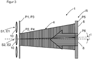
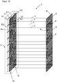
- FIG. 1 shows a reflection light grating with multiple light emitters S1, S2 and a plurality of light receivers E1, E2 in a housing 2 and an opposite retroreflective reflector R, the incoming light beams 4 parallel to their direction of incidence reflected back, wherein the retroreflective reflector R has at least a first portion 6 and at least a second portion 8, wherein a first light emitter S1, a first light receiver E1 and the first portion 6 of the reflector form a first reflection light barrier and a second light emitter S2, a second Light receiver E2 and the second portion 8 of the reflector R form a second reflection light barrier, wherein the first portion 6 and the second portion 8 have different polarization properties, in front of the first light emitter S1, a first polarization filter P1 with a first polarization direction and before the second light emitter, a second polarization filter P2 is arranged with a second polarization direction, in front of the first light receiver E1 a third polarization filter P3 with a
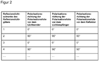
- the first polarization direction of the first polarization filter P1 and the polarization direction of the second polarization filter P2 differ by 90 °. Furthermore, the third polarization direction of the third polarization filter P3 and the fourth polarization direction of the fourth polarization filter P4 differ by 90 °. The first polarization direction of the first polarization filter P1 and the third polarization direction of the third polarization filter P3 do not differ, and the second polarization direction of the second polarization filter P2 and the fourth polarization direction of the fourth polarization filter P4 do not differ.
- the reflector R has a lens-like structure, so that the reflected light has the same direction of polarization as the incident light, wherein before the first portion 6 of the reflector R, a fifth polarization filter P5 is arranged with a fifth polarization direction and before the second section 8 of Reflektors R a sixth polarization filter P6 is arranged with a sixth polarization direction, wherein the fifth polarization direction of the fifth polarization filter P5 and the sixth polarization direction of the sixth polarization filter P6 differ by 90 °.
- the polarization direction of the first, third and fifth polarization filter is identical. Further, the polarization direction of the second, fourth and sixth polarizing filters is identical.
- the polarizing filters P1, P2, P3, P4, P5, P6 may be linear polarizing filters.
- the linear polarizing filters need only be arranged for the desired effect in a specific orientation, that is to say in a specific polarization direction. By using two different linear polarization directions, two adjacent reflection light barriers are optically separated according to the invention without mutual interference taking place.
- the polarization filters P1, P2, P3, P4, P5, P6 can be used according to FIG. 1 also be circular polarizing filter.
- Circular polarizing filters are formed by a linear polarizing filter and a ⁇ / 4 foil.
- the light emitter and / or the light receiver optionally have an optical system.
- the optic is preferably arranged between the light transmitter S1, S2 or light receiver E1, E2 and polarization filter P1, P2, P3, P4.
- the optics determine the beam divergence.
- the optics are formed in the simplest case by a diaphragm. However, the optics may also be formed by a lens or a lens system.
- the beam divergence with the angles ⁇ 1, ⁇ 2, ⁇ 1, ⁇ 2, the distances B between the light emitters and the light receivers and the distance A between the light emitter and the reflector are in FIG. 1 only shown schematically.
- the beam divergence is set, for example, at an angle ⁇ 1, ⁇ 2, ⁇ 1, ⁇ 2 from about 0 ° to about +/- 5 °.
- the light emitter S1 has the beam divergence at an angle ⁇ 1.
- the associated light receiver E1 has the reception divergence at an angle of ⁇ 1.
- the light emitter S2 has the beam divergence at the angle ⁇ 2.
- the associated light receiver E2 has the reception divergence at an angle ⁇ 2.
- the distances B between the light emitters S1, S2 and light receivers E1, E2 are about a few millimeters to a few centimeters.
- the distances A between light emitters S1, S2 or light receivers E1, E2 and the reflector R can be a few centimeters and up to several meters.
- a squint angle denotes the deviation of the light axis of the light emitters S1, S2 from the target direction.
- all light axes of the light emitters S1, S2 are aligned in parallel, as in FIG FIG. 1 shown.
- FIG. 2 shows in tabular form for the individual formed reflection light barriers of the light grid according to FIG. 1 exemplifies the orientation of the polarizing filter for light emitter, reflector and light receiver.
- FIG. 3 shows a light emitter S2 with beam divergence and a nearly parallel beam, which is reflected by the second portion 8 of the reflector R.
- a transmission beam of the light emitter S2 has at the location of the reflector R usually a larger diameter than a portion 8 of the reflector R toward the adjacent next section 6, as in FIG. 3 shown.
- the light beams of the light emitter S2 also have a squint angle ⁇ 1.
- the reflector alternately has first sections 6 and second sections 8, light only passes from the corresponding section to the receiver. The light is reflected back and received by the receiver.
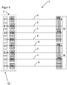
- FIG. 4 shows a reflection light grating 1 with alternately arranged light emitters S1, S2, S3, S4 and light receivers E1, E2, E3, E4 in a row 12 to form a plurality of reflection light barriers.
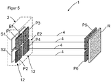
- FIG. 5 shows a double row arrangement of light emitters S1, S2 in a first row 12 and light receivers E1, E2 in a second row 12.
- FIG. 6 shows the arrangement FIG. 5 with a plurality of reflection light barriers formed to form a reflection light grating 1 with light emitters S1, S2 in a first row 12 and light receivers E1, E2 in a second row 12.
- FIG. 7 shows a two-row arrangement of light emitters S1 and light receivers E2 in a first row 12 and light emitters S2 and light receivers E1 in a second row 12. Respectively one light emitter S1, S2 of a row 12 and a light receiver E1, E2 of the other row form a reflection light barrier.
- FIG. 8 shows a reflection light grating formed of reflection light barriers, wherein light emitter S1, S2, S3, S4, S5, S6 and light receiver E1, E2, E3, E4, E5, E6 form an autocollimation.
- the light beams of the light emitter S1, S2, S3, S4, S5, S6 and the reflected light beams are collimated, ie they run within the same light path.
- the light beams 4 are emitted by a light transmitter S1 and pass through the first polarization filter P1. Thereafter, the light beams 4 pass through a semitransparent mirror 14. After passing through the surveillance area, the light beams 4 penetrate the fifth polarization filter P5, to be subsequently deflected by the retroreflector R by 180 °.
- the light beams 4 again pass through the fifth polarizing filter P5 and meet after passing through the surveillance area on the semitransparent mirror 14.
- the light beams 4 are deflected by the semitransparent mirror 14 by 90 ° and pass through a third polarizing filter P3. Thereafter, the light beams 4 hit the first light receiver E1.
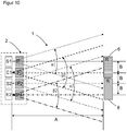
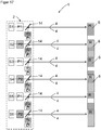
- FIG. 10 shows a reflection light grating with a plurality of light emitters S1, S2 and a plurality of light receivers E1, E2 in a housing 2 and an opposing retroreflective reflector R, the incoming light rays 4 parallel to their direction of incidence reflects back, wherein the retroreflective reflector R has at least a first portion 6 and at least one second section 8, wherein a first light emitter S1, a first light receiver E and the first portion 6 of the reflector form a first reflection light barrier and a second light emitter S2, a second light receiver E2 and the second portion 8 of the reflector R form a second reflection light barrier, wherein the first section 6 and the second section 8 have different polarization properties, in front of the first light emitter S1 a first polarization filter P1 having a first polarization direction and in front of the second light emitter a second polarization filter P2 having a second one arranged in front of the first light receiver E1 a third polarization filter P3 with a
- the first polarization direction of the first polarization filter P1 and the polarization direction of the second polarization filter P2 differ 45 °. Furthermore, the third polarization direction of the third polarization filter P3 and the fourth polarization direction of the fourth polarization filter P4 differ by 45 °. The first polarization direction of the first polarization filter P1 and the third polarization direction of the third polarization filter P3 differ by 90 °. The second polarization direction of the second polarization filter P2 and the fourth polarization direction of the fourth polarization filter P4 differ by 90 °.
- the reflector R has triple mirrors of plane mirror surfaces, which are each arranged at 90 ° to each other, so that the reflector R, depending on the orientation, the polarization direction of reflected light with respect to the incident light by 90 °.
- the first section 6 of the reflector R is rotated in such a way that maximum light passes from the first light emitter to the first receiver and the second section 8 of the reflector R is rotated in such a way that a maximum of light passes from the second light emitter to the second receiver, whereby the angle of rotation the first portion of the reflector and the second portion of the reflector by 45 °.
- FIG. 11 shows in tabular form for the individual formed reflection light barriers of the light grid according to FIG. 10 for example, the orientation of the polarizing filter for light emitter and light receiver and the orientation of the sections of the reflector.
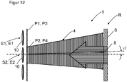
- FIG. 12 shows a light emitter S2 with beam divergence and a nearly parallel beam that passes through the second portion 8 of the reflector R to the corresponding receiver.
- a transmission beam of the light emitter S2 has at the location of the reflector R usually a larger diameter than a portion 8 of the reflector R toward the adjacent next section 6, as in FIG. 3 shown.
- the light beams of the light emitter S2 also have a squint angle ⁇ 1. Due to the polarization-selective arrangement of the light transmitter S2, section 8 of the reflector and light receiver E2, the light predominantly passes from the section 8 back to the corresponding receiver E2. The diameter of the beam is thus reduced to the extent of the portion 8 of the reflector. Since the reflector alternately has first sections 6 and second sections 8, light only passes from the corresponding section to the receiver. The light is reflected back and received by the receiver.
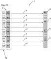
- FIG. 13 shows a reflection light grating 1 with alternately arranged light emitters S1, S2, S3, S4 and light receivers E1, E2, E3, E4 in a row 12 and opposite portions 6 and 8 of the reflector R to form a plurality of reflection light barriers.
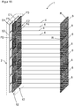
- FIG. 14 shows a double row arrangement of light emitters S1, S2 in a first row 12 and light receivers E1, E2 in a second row 12 and opposite reflector portions 6 and 8.
- FIG. 15 shows the arrangement FIG. 14 with a multiplicity of reflection light barriers formed to form a reflection light grid 1 with light transmitters S1, S2 in a first row 12 and light receivers E1, E2 in a second row 12 and opposite alternately arranged reflector sections 6 and 8.
- FIG. 16 shows a two-row arrangement of light emitters S1 and light receivers E2 in a first row 12 and light emitters S2 and light receivers E1 in a second row 12. Respectively one light emitter S1, S2 of a row 12 and a light receiver E1, E2 of the other row form a reflection light barrier.
- FIG. 17 shows a reflection light grating formed of reflection light barriers, wherein light emitter S1, S2, S3, S4, S5, S6 and light receiver E1, E2, E3, E4, E5, E6 form an autocollimation.
- the light beams of the light emitter S1, S2, S3, S4, S5, S6 and the reflected light beams are collimated, ie they run within the same light path.
- the light beams 4 are emitted by a light transmitter S1 and pass through the first polarization filter P1. Thereafter, the light beams 4 pass through a semi-transparent mirror 14. After passing through the monitoring area, the light beams are deflected by the retroreflector R by 180 °.
- the sections 6 and 8 of the reflector according to the table according to FIG.
- the light beams After passing through the surveillance area, the light beams strike the semitransparent mirror 14.
- the light beams 4 are deflected by the semitransparent mirror 14 by 90 ° and penetrate a third polarization filter P3. Thereafter, the light beams 4 hit the first light receiver E1.
- FIG. 18 shows by way of example the signal of polarized light when reflected at the portion of the reflector at different angles of rotation of the portion of the reflector. With the rotation angles 0 °, 90 °, 180 ° and 270 ° the highest signal of more than 90% is reached. At the angles of rotation 45 °, 135 °, 225 ° and 315 °, the lowest signal of less than 10% is achieved.
- FIG. 19 shows a combination of the device according to FIG. 4 and FIG. 13 ,
- the light of the light emitters S1 and S2 is filtered by the polarization filters P5 and P6 in front of the reflector R.
- the light of the light emitters S3 and S4 points through the color filters or bandpass filters F1 and F2 light of different wavelength.
- the light of the light emitters S5 and S5 is finally filtered by differently oriented sections 6 and 8 of the reflectors.
- FIG. 20 shows a reflection light grating formed by reflection light barriers, light transmitters S1, S2, S3, S4, S5, S6 and light receivers E1, E2, E3, E4, E5, E6 forming an autocollimation arrangement.
- the light beams of the light emitter S1, S2, S3, S4, S5, S6 and the reflected light beams are collimated, i. These run within the same light path.
- the light beams 4 are emitted by a light transmitter S1 and pass through the first polarization filter P1. Thereafter, the light beams 4 pass through a semitransparent mirror 14. After passing through the surveillance area, the light beams 4 penetrate the fifth polarization filter P5, to be subsequently deflected by the retroreflector R by 180 °.
- the light beams 4 again pass through the fifth polarizing filter P5 and meet after passing through the surveillance area on the semitransparent mirror 14.
- the light beams 4 are deflected by the semitransparent mirror 14 by 90 ° and penetrate a third polarizing filter P3. Thereafter, the light beams 4 hit the first light receiver E1.
- the light of the light emitters S1 and S2 is filtered by the polarization filters P5 and P6 in front of the reflector R.
- the light of the light emitters S3 and S4 is filtered by differently oriented sections 6 and 8 of the reflectors.
- the light of the light emitters S3 and S4 has light of different wavelengths through the color filters or bandpass filters F1 and F2.
Description
Die vorliegende Erfindung betrifft ein Reflexionslichtgitter mit mehreren Lichtsendern und mehreren Lichtempfängern in einem Gehäuse und einem gegenüberliegenden retroreflektierenden Reflektor, der eingehende Lichtstrahlen nahezu parallel zu Ihrer Einfallsrichtung zurückreflektiert, wobei der retroreflektierende Reflektor mindestens einen ersten Abschnitt aufweist und mindestens einen zweiten Abschnitt aufweist, wobei ein erster Lichtsender, ein erster Lichtempfänger und der erste Abschnitt des Reflektors eine Reflexionslichtschranke bilden und ein zweiter Lichtsender, ein zweiter Lichtempfänger und der zweite Abschnitt des Reflektors eine zweite Reflexionslichtschranke bilden.The present invention relates to a reflective light grid having a plurality of light emitters and a plurality of light receivers in a housing and an opposed retroreflective reflector that reflects incoming light rays nearly parallel to their direction of incidence, the retroreflective reflector having at least a first portion and having at least a second portion, wherein a first Light transmitter, a first light receiver and the first portion of the reflector form a reflection light barrier and form a second light emitter, a second light receiver and the second portion of the reflector, a second reflection light barrier.
Im Gegensatz zu Einstrahlsensoren, bei denen der gesamte Sensor ausgerichtet werden kann, muss bei einem Reflexionslichtgitter ein relativer Schielwinkel zwischen den Lichtsendern minimal gehalten werden, um einen Sensor mit ausreichender Messgenauigkeit zu gewährleisten. Eine vollständige Vermeidung des relativen Schielwinkels ist aufgrund von Bauteiltoleranzen jedoch nicht zu gewährleisten. Des Weiteren ist das Strahlenbündel eines Lichtsenders ab einem gewissen Abstand divergent, d. h. der Durchmesser des Lichtspots nimmt mit größer werdendem Abstand zu.In contrast to single-beam sensors, where the entire sensor can be aligned, with a reflection light grating, a relative squint angle between the light transmitters must be kept to a minimum, in order to ensure a sensor with sufficient measuring accuracy. However, a complete avoidance of the relative squint angle is not guaranteed due to component tolerances. Furthermore, the beam of a light emitter is divergent at a certain distance, i. H. The diameter of the light spot increases with increasing distance.
Ein Reflexionslichtgitter benötigt einen Reflektor mit entsprechender Länge, so dass alle Lichtsenderstrahlenbündel reflektiert werden. Nachteilig hierbei ist, dass dadurch der vollständige Lichtspot reflektiert wird. Abhängig vom Reflektorabstand und der Strahlbündeldivergenz wird dieser Lichtspot deutlich größer als die Senderlinse. Zusätzlich gibt es einen Versatz des Lichtspots aufgrund des Schielwinkels. Da der vollständige Lichtspot reflektiert wird, muss auch der vollständige Lichtspot von dem zu detektierenden Objekt abgedeckt werden. Die Genauigkeit und ein minimal detektierbares Objekt sind bei Verwendung eines herkömmlichen Reflektors daher abhängig von der Größe und der Lage des Senderlichtspots auf dem Reflektor, bzw. im Messfeld oder Überwachungsfeld.A reflection light grating requires a reflector of appropriate length, so that all light emitter beams are reflected. The disadvantage here is that this reflects the complete light spot. Depending on the reflector distance and the beam divergence, this light spot becomes significantly larger than the transmitter lens. In addition, there is an offset of the light spot due to the squint angle. Since the complete light spot is reflected, the complete light spot must also be covered by the object to be detected. The accuracy and a minimum detectable object are therefore dependent when using a conventional reflector the size and position of the transmitter light spot on the reflector, or in the measuring field or monitoring field.
Die
Die
Die
Die
Die
Eine Aufgabe der Erfindung besteht darin, ein Reflexionslichtgitter bereitzustellen, das für die Vermessung von Gegenständen geeignet ist und eine höhere Auflösung aufweist.An object of the invention is to provide a reflection light grid which is suitable for the measurement of objects and has a higher resolution.
Die Aufgabe wird gemäß Anspruch 1 gelöst.The problem is solved according to
Durch das erfindungsgemäße Reflexionslichtgitter gelangt das Licht eines Lichtsenders vorwiegend über einen entsprechenden Abschnitt des Reflektors zum entsprechenden Lichtempfänger der Reflexionslichtschranke. Das Licht, welches auf die benachbarten Abschnitte des Reflektors gelangt, trifft vernachlässigbar auf den Lichtempfänger der Reflexionslichtschranke.By means of the reflection light grating according to the invention, the light of a light emitter predominantly passes over a corresponding section of the reflector to the corresponding light receiver of the reflection light barrier. The light which reaches the adjacent sections of the reflector, meets negligibly on the light receiver of the reflection light barrier.
Ein Sendestrahlbündel des Lichtsenders hat am Ort des Reflektors im Regelfall einen größeren Durchmesser als ein Abschnitt des Reflektors in Richtung zu dem benachbarten nächsten Abschnitt. Durch die polarisationsselektive Anordnung von Lichtsender, Abschnitt des Reflektors und Lichtempfänger gelangt vorwiegend das Licht aus einem Abschnitt zurück zum entsprechenden Empfänger. Der Durchmesser des Strahlenbündels reduziert sich damit auf die Ausdehnung des Abschnittes des Reflektors. D. h. es wird zwar von jedem Abschnitt Licht reflektiert, jedoch ist das Licht unterschiedlich polarisiert, so dass unterschiedlich polarisiertes Licht auf die verschiedenen Empfänger gelangt, also nur jeweils der 'richtige' Teil des Lichtes.A transmission beam of the light transmitter has at the location of the reflector usually has a larger diameter than a portion of the reflector toward the adjacent next section. Due to the polarization-selective arrangement of light emitter, section of the reflector and light receiver mainly passes the light a section back to the appropriate recipient. The diameter of the beam is thus reduced to the extent of the portion of the reflector. Ie. although light is reflected by each section, the light is differently polarized so that differently polarized light reaches the different receivers, ie only the 'right' part of the light.
Da die regelmäßigen Abschnitte des Reflektors das Raster für das reflektierte Licht vorgeben, wird erfindungsgemäß auch ein ggf. vorhandener Lichtsenderschielwinkel kompensiert, da lediglich die auf den Abschnitt des Reflektors treffenden Lichtstrahlen auf den entsprechenden Empfänger gelangen.Since the regular sections of the reflector predetermine the raster for the reflected light, according to the invention, any light transmitter squint angle which may be present is also compensated, since only the light beams striking the section of the reflector reach the corresponding receiver.
Da das reflektierte Licht gemäß dem erfindungsgemäßen Reflexionslichtgitter nur aus einem definierten Abschnitt der Reflektors in den Empfänger gelangt, wird eine minimal zu detektierende Objektgröße kleiner und damit wird eine bessere Objektdetektion erreicht. Dadurch ist auch eine verbesserte Genauigkeit bei der Vermessung von Gegenständen erreicht.Since the reflected light passes according to the reflection light grating according to the invention only from a defined portion of the reflector in the receiver, a minimum object size to be detected is smaller, and thus a better object detection is achieved. As a result, an improved accuracy in the measurement of objects is achieved.
Gemäß der Erfindung wird eine Auflösung des Reflexionslichtgitters verbessert, so dass die beste Auflösung nur durch die Größe der Abschnitte des Reflektors bestimmt wird und einer Einstellung von Schaltschwellen. Die Auflösung ist dabei unabhängig von der Strahldivergenz und dem Schielwinkel.According to the invention, a resolution of the reflection light grating is improved, so that the best resolution is determined only by the size of the sections of the reflector and an adjustment of switching thresholds. The resolution is independent of the beam divergence and the squint angle.
Gemäß einer ersten Alternative der Erfindung sind die Lichtsender direkt benachbart in einer Reihe angeordnet und die Lichtempfänger parallel zu den Lichtsendern direkt benachbart in einer Reihe angeordnet. Dabei bildet auch jeder Lichtsender und jeder benachbarte Lichtempfänger eine Reflexionslichtschranke. Dabei wird im Vergleich zu einer einreihigen Lösung eine doppelt so hohe Auflösung, also auch ein doppelt so feines Abtastraster erzielt.According to a first alternative of the invention, the light emitters are arranged directly adjacent in a row and the light receivers are arranged parallel to the light emitters directly adjacent in a row. Each light transmitter and each adjacent light receiver also forms a reflection light barrier. In this case, compared to a single-row solution, a resolution twice as high, that is also a twice as fine sampling raster, is achieved.
Gemäß einer zweiten Alternative der Erfindung sind die Lichtsender und Lichtempfänger jeweils in zwei Reihen angeordnet, wobei sich Lichtsender und Lichtempfänger in einer Reihe abwechseln und jedem Lichtsender der einen Reihe ein Lichtempfänger der anderen Reihe zugeordnet ist. Dabei bildet auch jeder Lichtsender und jeder benachbarte Lichtempfänger eine Reflexionslichtschranke. Dabei wird im Vergleich zu einer einreihigen Lösung auch eine doppelt so hohe Auflösung, also auch ein doppelt so feines Abtastraster erzielt.According to a second alternative of the invention, the light emitter and light receiver are each arranged in two rows, with light emitter and light receiver alternating in a row and each light emitter of one row is assigned a light receiver of the other row. Each light transmitter and each adjacent light receiver also forms a reflection light barrier. In this case, in comparison to a single-row solution, a resolution twice as high, that is to say a twice as fine sampling raster, is achieved.
In Weiterbildung der Erfindung unterscheiden sich die erste Polarisationsrichtung des ersten Polarisationsfilters und die Polarisationsrichtung des zweiten Polarisationsfilters um 45°. Weiter unterscheiden sich die dritte Polarisationsrichtung des dritten Polarisationsfilters und die vierte Polarisationsrichtung des vierten Polarisationsfilters um 45°. Die erste Polarisationsrichtung von dem ersten Polarisationsfilter und die dritte Polarisationsrichtung von dem dritten Polarisationsfilter unterscheiden sich um 90°. Die zweite Polarisationsrichtung von dem zweiten Polarisationsfilter und die vierte Polarisationsrichtung von dem vierten Polarisationsfilter unterscheiden sich um 90°. Der Reflektor weist Tripelspiegel aus planen Spiegelflächen auf, die jeweils um 90° zueinander angeordnet sind, so dass der Reflektor je nach Orientierung die Polarisationsrichtung von reflektiertem Licht gegenüber dem einfallendem Licht um 90° dreht. Der erste Abschnitt des Reflektors ist derart gedreht, dass maximal viel Licht vom ersten Lichtsender zum ersten Empfänger gelangt und der zweite Abschnitt des Reflektors ist derart gedreht, dass maximal viel Licht vom zweiten Lichtsender zum zweiten Empfänger gelangt, wobei sich der Drehwinkel des ersten Abschnitts des Reflektors und des zweiten Abschnitts des Reflektors um 45° unterscheiden.In a development of the invention, the first polarization direction of the first polarization filter and the polarization direction of the second polarization filter differ by 45 °. Furthermore, the third polarization direction of the third polarization filter and the fourth polarization direction of the fourth polarization filter differ by 45 °. The first polarization direction of the first polarization filter and the third polarization direction of the third polarization filter differ by 90 °. The second polarization direction of the second polarization filter and the fourth polarization direction of the fourth polarization filter differ by 90 °. The reflector has triple mirrors made of plane mirror surfaces, which are each arranged at 90 ° to one another, so that the reflector, depending on the orientation, rotates the polarization direction of reflected light with respect to the incident light by 90 °. The first portion of the reflector is rotated such that a maximum of light from the first light emitter reaches the first receiver and the second portion of the reflector is rotated such that maximum amount of light from the second light emitter to the second receiver passes, wherein the angle of rotation of the first portion of the reflector and the second portion of the reflector differ by 45 °.
Durch die Anordnung von drei Planflächen oder planen Spiegelflächen im Winkel von jeweils 90° wird ein eingehender Lichtstrahl durch Totalreflexion an allen drei Flächen reflektiert und läuft parallel zu seiner Einfallsrichtung wieder zurück.By arranging three plane surfaces or plane mirror surfaces at an angle of 90 °, an incoming light beam is reflected by total reflection on all three surfaces and runs back parallel to its direction of incidence.
In einer alternativen Weiterbildung der Erfindung unterscheiden sich die erste Polarisationsrichtung des ersten Polarisationsfilters und die Polarisationsrichtung des zweiten Polarisationsfilters um 90°. Weiter unterscheiden sich die dritte Polarisationsrichtung des dritten Polarisationsfilters und die vierte Polarisationsrichtung des vierten Polarisationsfilters um 90°. Die erste Polarisationsrichtung von dem ersten Polarisationsfilter und die dritte Polarisationsrichtung von dem dritten Polarisationsfilter unterscheiden sich nicht und die zweite Polarisationsrichtung von dem zweiten Polarisationsfilter und die vierte Polarisationsrichtung von dem vierten Polarisationsfilter unterscheiden sich nicht. Der Reflektor weist eine linsenähnliche Struktur auf, so dass das reflektierte Licht die gleiche Polarisationsrichtung aufweist, wie das einfallende Licht, wobei vor dem ersten Abschnitt des Reflektors ein fünftes Polarisationsfilter mit einer fünften Polarisationsrichtung angeordnet ist und vor dem zweiten Abschnitt des Reflektors ein sechstes Polarisationsfilter mit einer sechsten Polarisationsrichtung angeordnet ist, wobei sich die fünfte Polarisationsrichtung des fünften Polarisationsfilters und die sechste Polarisationsrichtung des sechsten Polarisationsfilters um 90° unterscheiden.In an alternative development of the invention, the first polarization direction of the first polarization filter and the polarization direction of the second polarization filter differ by 90 °. Furthermore, the third polarization direction of the third polarization filter and the fourth polarization direction of the fourth polarization filter differ by 90 °. The first polarization direction of the first polarization filter and the third polarization direction of the third polarization filter do not differ and the second polarization direction of the second polarization filter and the fourth polarization direction of the fourth polarization filter do not differ. The reflector has a lens-like structure, so that the reflected light has the same direction of polarization as the incident light, wherein before the first portion of the reflector, a fifth polarizing filter is arranged with a fifth polarization direction and before the second portion of the reflector, a sixth polarization filter a sixth polarization direction is arranged, wherein the fifth polarization direction of the fifth polarization filter and the sixth polarization direction of the sixth polarization filter differ by 90 °.
Bei einem Reflektor mit einer linsenähnlichen Struktur wird die Polarisationsrichtung zwischen eingehendem und ausgehendem Licht nicht gedreht. Gemäß dieser Weiterbildung der Erfindung ist nun vor jedem Abschnitt des Reflektors ein Polarisationsfilter angeordnet, so dass das Licht eines zugehörigen Lichtsenders über den zugehörigen Abschnitts des Reflektors auf den zugehörigen Lichtempfänger gelangt.In a reflector having a lens-like structure, the polarization direction between incoming and outgoing light is not rotated. According to this embodiment of the invention, a polarization filter is now arranged in front of each section of the reflector, so that the light of an associated light transmitter passes via the associated portion of the reflector to the associated light receiver.
In Weiterbildung der Erfindung weisen die Lichtsender und/oder die Lichtempfänger eine Optik auf. Die Optik ist dabei vorzugsweise zwischen Lichtsender bzw. Lichtempfänger und Polarisationsfilter angeordnet. Durch die Optik wird die Strahldivergenz bestimmt. Die Optik wird im einfachsten Fall durch eine Blende gebildet. Jedoch kann die Optik auch durch eine Linse oder auch ein Linsensystem gebildet sein.In a development of the invention, the light transmitters and / or the light receivers have optics. The optic is preferably arranged between light transmitter or light receiver and polarization filter. The optics determine the beam divergence. The optics are formed in the simplest case by a diaphragm. However, the optics may also be formed by a lens or a lens system.
Die Strahldivergenz wird beispielsweise in einem Winkel von 0°, also parallelen Lichtstrahlen bis ca. +/-5° eingestellt. Je kleiner die Strahldivergenz ist, desto größer kann der Abstand zwischen den Lichtsendern bzw. Lichtempfängern und dem Reflektor gewählt werden.The beam divergence is set, for example, at an angle of 0 °, ie parallel light beams up to approximately +/- 5 °. The smaller the beam divergence, the larger it can be the distance between the light emitters or light receivers and the reflector can be selected.
Mit Hilfe der Optik wird auch ein möglicher Schielwinkel des Lichtsenders kompensiert und im idealen Fall ganz vermieden, so dass der Schielwinkel 0° beträgt. Ein Schielwinkel bezeichnet dabei die Abweichung der Lichtachse der Lichtsender von der Sollrichtung. Im idealen Fall sind alle Lichtachsen der Lichtsender parallel ausgerichtet.With the aid of the optics, a possible squint angle of the light emitter is compensated and in the ideal case completely avoided, so that the squint angle is 0 °. A squint angle refers to the deviation of the light axis of the light emitter from the desired direction. In the ideal case, all light axes of the light emitters are aligned in parallel.
In einer bevorzugten Ausführungsform sind die Polarisationsfilter lineare Polarisationsfilter. Lineare Polarisationsfilter sind einfach herstellbar und daher preiswert. Die linearen Polarisationsfilter brauchen lediglich für die gewünschte Wirkung in einer bestimmten Orientierung, also in einer bestimmten Polarisationsrichtung angeordnet werden. Durch die Verwendung von zwei unterschiedlichen linearen Polarisationsrichtungen können erfindungsgemäß zwei benachbarte Reflexionslichtschranken optisch getrennt werden, ohne dass eine gegenseitige Beeinflussung stattfindet.In a preferred embodiment, the polarization filters are linear polarization filters. Linear polarizing filters are easy to manufacture and therefore inexpensive. The linear polarizing filters need only be arranged for the desired effect in a specific orientation, that is to say in a specific polarization direction. By using two different linear polarization directions, according to the invention, two adjacent reflection light barriers can be optically separated without mutual interference taking place.
In Weiterbildung sind die Polarisationsfilter zirkuläre Polarisationsfilter. Zirkulare Polarisationsfilter werden durch ein lineares Polarisationsfilter und eine λ/4 Folie gebildet.
In Weiterbildung der Erfindung trifft das Sendelicht eines Lichtsenders nur maximal drei gegenüberliegende Abschnitte des Reflektors. Dies wird durch eine geeignete Wahl der Strahldivergenz der Lichtsender und durch den Abstand zwischen den Lichtsendern bzw. Lichtempfängern und dem Reflektor sowie der Abstände der Lichtsender zueinander erreicht. Der Schielwinkel und die Strahldivergenz definieren gemeinsam den maximalen Abstand des Reflektors. Je kleiner die Strahldivergenz der Lichtsender ist und je weiter die Abstände zwischen den Lichtsendern sind, desto größer kann der Abstand zwischen Lichtsender bzw. Lichtempfänger und Reflektor betragen. Je höher jedoch die Messauflösung des Reflexionslichtgitters gewünscht wird, desto geringer müssen die Abstände zwischen den Lichtsendern bzw. zwischen den Lichtempfängern sein.In a further development, the polarization filters are circular polarization filters. Circular polarizing filters are formed by a linear polarizing filter and a λ / 4 foil.
In a further development of the invention, the transmitted light of a light transmitter meets only a maximum of three opposite sections of the reflector. This is achieved by a suitable choice of the beam divergence of the light emitter and by the distance between the light emitters or light receivers and the reflector and the distances of the light emitter to each other. The squint angle and the beam divergence together define the maximum distance of the reflector. The smaller the beam divergence of the light emitter and the farther the distances between the light emitters, the greater the distance between the light emitter or light receiver and the reflector. However, the higher the measurement resolution of the reflection light grating is desired, the smaller the distances between the light emitters or between the light receivers must be.
In Weiterbildung der Erfindung weist das Licht unterschiedlicher Lichtsender unterschiedliche Wellenlängen auf und die zugehörigen Lichtempfänger sind nur für diese Wellenlänge empfindlich. Dadurch ist es möglich, eine noch größere Anzahl von Reflexionslichtschranken optisch zu entkoppeln. Beispielsweise können zwei Lichtsender mit identischer Polarisationsrichtung durch Licht unterschiedlicher Wellenlänge optisch voneinander entkoppelt werden. In Weiterbildung der Erfindung sind vor den Lichtsendern, den Lichtempfängern und dem Reflektor jeweils Farbfilter oder Bandpassfilter angeordnet.
Die Lichtsender können von einer Leuchtdiode (LED), einem 'Vertical-Cavity Surface Emitting Laser' (VCSEL), einer Laserdiode oder ähnlichem gebildet sein oder aus einer Kombination dieser Lichtquellen.
In Weiterbildung der Erfindung triff das Sendelicht eines Lichtsenders nur maximal fünf gegenüberliegende Abschnitte des Reflektors. Dies wird durch eine geeignete Wahl der Strahldivergenz der Lichtsender und durch den Abstand zwischen den Lichtsendern bzw. Lichtempfängern und dem Reflektor sowie der Abstände der Lichtsender zueinander erreicht. Dabei werden mindestens vier benachbarte Lichtsender optisch voneinander entkoppelt.In a development of the invention, the light of different light transmitters has different wavelengths and the associated light receivers are sensitive only to this wavelength. This makes it possible to optically decouple an even larger number of reflection light barriers. For example, two light transmitters with identical polarization direction can be optically decoupled from one another by light of different wavelengths. In a further development of the invention, color filters or bandpass filters are arranged in each case in front of the light transmitters, the light receivers and the reflector.
The light emitters may be formed by a light emitting diode (LED), a vertical cavity surface emitting laser (VCSEL), a laser diode or the like, or a combination of these light sources.
In a further development of the invention, the transmitted light of a light transmitter meets only a maximum of five opposite sections of the reflector. This is achieved by a suitable choice of the beam divergence of the light emitter and by the distance between the light emitters or light receivers and the reflector and the distances of the light emitter to each other. At least four adjacent light emitters are optically decoupled from each other.
Weiter kann beispielsweise das Reflexionslichtgitter eine Ausrichthilfe aufweisen, welche durch einen Orientierungsstrahl gebildet ist, beispielsweise einen Laserstrahl. Die Ausrichthilfe dient dazu, das Gehäuse auf den Reflektor und/oder den Reflektor auf das Gehäuse auszurichten.Further, for example, the reflection light grating having an alignment, which is formed by an orientation beam, for example, a laser beam. The alignment aid serves to align the housing on the reflector and / or the reflector on the housing.
Zum Betrieb wird beispielsweise das Reflexionslichtgitter relativ zum Reflektor ausgerichtet oder der Reflektor relativ zum Reflexionslichtgitter. Hierfür wird beispielsweise der Reflektor lagefest fixiert. Das Reflexionslichtgitter befindet sich in einer Aufnahme, in dem es rotiert und verschoben werden kann. Im ersten Schritt wird das Reflexionslichtgitter rotiert, bis sich das Senderlichtspotarray vollständig auf dem Reflektor befindet. Im zweiten Schritt wird das Reflexionslichtgitter in Längsrichtung verschoben und währenddessen ein Ausrichtsignal erzeugt. Dieses Ausrichtsignal kann beispielsweise ein Empfangssignal oder die Summe aller Empfangssignale sein. Bei optimaler Ausrichtung ist dieses Ausrichtsignal vorzugsweise maximal.
Die Erfindung wird nachstehend auch hinsichtlich weiterer Vorteile und Merkmale unter Bezugnahme auf die beigefügte Zeichnung anhand von Ausführungsbeispielen erläutert. Die Figuren der Zeichnung zeigen in:
Figur 1- ein Reflexionslichtgitter gemäß der Erfindung;
Figur 2- eine Tabelle mit Polarisationsrichtungen für einzelne Reflexionslichtschranken des Reflexionslichtgitters;
Figur 3- einen Lichtsender mit Sendedivergenz und ein Abschnitt des Reflektors;
Figur 4- ein Reflexionslichtgitter mit mehreren Lichtsendern und Lichtempfängern in einer Reihe;
- Figur 5 und 6
- ein Reflexionslichtgitter mit Lichtsendern und Lichtempfängern in zwei Reihen;
- Figur 7
- ein Reflexionslichtgitter mit Lichtsendern und Lichtempfängern in einer ersten Reihe und Lichtsender und Lichtempfänger in einer zweiten Reihe;
Figur 8- ein Reflexionslichtgitter mit einer autokollimativen Reflexionslichtschrankenanordnung;
Figur 10- ein Reflexionslichtgitter gemäß der Erfindung mit jeweils gedrehten Abschnitten des Reflektors;
- Figur 11
- eine Tabelle mit Ausrichtwinkeln für die Abschnitte des Reflektors;
Figur 12- einen Lichtsender mit Sendedivergenz und ein Abschnitt des Reflektors;
- Figur 13
- ein Reflexionslichtgitter mit mehreren Lichtsendern und Lichtempfängern in einer Reihe und einem Reflektor mit Abschnitten in einer Reihe;
Figur 14 und 15- ein Reflexionslichtgitter mit Lichtsendern in einer Reihe und Lichtempfängern in einer Reihe und ein Reflektor mit zwei unterschiedlichen Abschnitten;
- Figur 16
- ein Reflexionslichtgitter mit Lichtsendern und Lichtempfängern in einer ersten Reihe und Lichtsendern und Lichtempfängern in einer zweiten Reihe und alternierenden Abschnitte von Reflektoren;
- Figur 17
- ein Reflexionslichtgitter mit einer autokollimativen Reflexionslichtschrankenanordnung und alternierenden Abschnitten von Reflektoren;
- Figur 18
- eine Darstellung des Signals von Reflektorabschnitten abhängig vom Drehwinkel des Reflektors;
- Figur 19
- eine Reflexionslichtgitter gemäß der Erfindung mit jeweils gedrehten Abschnitten des Reflektors, mit Lichtsendern unterschiedlicher Wellenlänge und Polarisationsfiltern vor Abschnitten des Reflektors;
Figur 20- ein Reflexionslichtgitter mit einer autokollimativen Reflexionslichtschrankenanordnung mit jeweils gedrehten Abschnitten des Reflektors, mit Lichtsendern unterschiedlicher Wellenlänge und Polarisationsfiltern vor Abschnitten des Reflektors.
The invention will be explained below with regard to further advantages and features with reference to the accompanying drawings with reference to embodiments. The figures of the drawing show in:
- FIG. 1
- a reflection light grid according to the invention;
- FIG. 2
- a table with polarization directions for individual reflection light barriers of the reflection light grid;
- FIG. 3
- a light transmitter with transmitting divergence and a portion of the reflector;
- FIG. 4
- a reflection light grid having a plurality of light emitters and light receivers in a row;
- FIGS. 5 and 6
- a reflection light grid with light emitters and light receivers in two rows;
- FIG. 7
- a reflection light grid having light emitters and light receivers in a first row and light emitters and light receivers in a second row;
- FIG. 8
- a reflection light grid with an autocollimated reflection light barrier arrangement;
- FIG. 10
- a reflection light grating according to the invention, each with rotated portions of the reflector;
- FIG. 11
- a table with alignment angles for the sections of the reflector;
- FIG. 12
- a light transmitter with transmitting divergence and a portion of the reflector;
- FIG. 13
- a reflection light grid having a plurality of light emitters and light receivers in a row and a reflector having sections in a row;
- FIGS. 14 and 15
- a reflection light grating with light emitters in a row and light receivers in a row and a reflector with two different sections;
- FIG. 16
- a reflection light grating comprising light emitters and light receivers in a first row and light emitters and light receivers in a second row and alternating portions of reflectors;
- FIG. 17
- a reflection light grid having an autocollimated reflection light barrier arrangement and alternating sections of reflectors;
- FIG. 18
- a representation of the signal of reflector sections depending on the angle of rotation of the reflector;
- FIG. 19
- a reflection light grating according to the invention, each with rotated portions of the reflector, with light emitters of different wavelengths and polarizing filters in front of portions of the reflector;
- FIG. 20
- a reflection light grid with an autocollimated reflection light barrier arrangement, each with rotated portions of the reflector, with light emitters of different wavelengths and polarizing filters before sections of the reflector.
In den nachfolgenden Figuren sind identische Teile mit identischen Bezugszeichen versehen.In the following figures, identical parts are provided with identical reference numerals.
Gemäß
Bei den Polarisationsfiltern P1, P2, P3, P4, P5, P6 kann es sich um lineare Polarisationsfilter handeln. Die linearen Polarisationsfilter brauchen lediglich für die gewünschte Wirkung in einer bestimmten Orientierung, also in einer bestimmten Polarisationsrichtung angeordnet werden. Durch die Verwendung von zwei unterschiedlichen linearen Polarisationsrichtungen werden erfindungsgemäß zwei benachbarte Reflexionslichtschranken optisch getrennt, ohne dass eine gegenseitige Beeinflussung stattfindet.The polarizing filters P1, P2, P3, P4, P5, P6 may be linear polarizing filters. The linear polarizing filters need only be arranged for the desired effect in a specific orientation, that is to say in a specific polarization direction. By using two different linear polarization directions, two adjacent reflection light barriers are optically separated according to the invention without mutual interference taking place.
Die Polarisationsfilter P1, P2, P3, P4, P5, P6 können gemäß
Die Lichtsender und/oder die Lichtempfänger weisen optional eine Optik auf. Die Optik ist dabei vorzugsweise zwischen Lichtsender S1, S2 bzw. Lichtempfänger E1, E2 und Polarisationsfilter P1, P2, P3, P4 angeordnet. Durch die Optik wird die Strahldivergenz bestimmt. Die Optik wird im einfachsten Fall durch eine Blende gebildet. Jedoch kann die Optik auch durch eine Linse oder auch ein Linsensystem gebildet sein.The light emitter and / or the light receiver optionally have an optical system. The optic is preferably arranged between the light transmitter S1, S2 or light receiver E1, E2 and polarization filter P1, P2, P3, P4. The optics determine the beam divergence. The optics are formed in the simplest case by a diaphragm. However, the optics may also be formed by a lens or a lens system.
Die Strahldivergenz mit den Winkeln α1, α2, β1, β2, die Abstände B zwischen den Lichtsendern und Lichtempfängern und der Abstand A zwischen dem Lichtsender bzw. Lichtempfänger und dem Reflektor sind in
Die Strahldivergenz wird beispielsweise in einem Winkel α1, α2, β1, β2 von ca. 0° bis ca. +/-5° eingestellt. Je kleiner die Strahldivergenz ist, desto größer kann der Abstand zwischen den Lichtsendern bzw. Lichtempfängern und dem Reflektor gewählt werden. Dabei weist der Lichtsender S1 die Strahldivergenz mit einem Winkel α1 auf. Der zugehörige Lichtempfänger E1 weist die Empfangsdivergenz mit einem Winkel von β1 auf. Der Lichtsender S2 weist die Strahldivergenz mit dem Winkel α2 auf. Der zugehörige Lichtempfänger E2 weist die Empfangsdivergenz mit einem Winkel β2 auf.The beam divergence is set, for example, at an angle α1, α2, β1, β2 from about 0 ° to about +/- 5 °. The smaller the beam divergence, the greater the distance between the light emitters or light receivers and the reflector can be selected. In this case, the light emitter S1 has the beam divergence at an angle α1. The associated light receiver E1 has the reception divergence at an angle of β1. The light emitter S2 has the beam divergence at the angle α2. The associated light receiver E2 has the reception divergence at an angle β2.
Die Abstände B zwischen den Lichtsendern S1, S2 und Lichtempfängern E1, E2 betragen ca. wenige Millimeter bis wenige Zentimeter. Die Abstände A zwischen Lichtsendern S1, S2 bzw. Lichtempfängern E1, E2 und dem Reflektor R können wenige Zentimeter und bis zu mehreren Metern betragen.The distances B between the light emitters S1, S2 and light receivers E1, E2 are about a few millimeters to a few centimeters. The distances A between light emitters S1, S2 or light receivers E1, E2 and the reflector R can be a few centimeters and up to several meters.
Mit Hilfe der Optik wird auch ein möglicher Schielwinkel des Lichtsenders S1, S2 kompensiert und im idealen Fall ganz vermieden, so dass der Schielwinkel 0° beträgt. Ein Schielwinkel bezeichnet dabei die Abweichung der Lichtachse der Lichtsender S1, S2 von der Sollrichtung. Im idealen Fall sind alle Lichtachsen der Lichtsender S1, S2 parallel ausgerichtet, wie in
Gemäß
Figur 20 zeigt ein Reflexionslichtgitter, gebildet aus Reflexionslichtschranken, wobei Lichtsender S1, S2, S3, S4, S5, S6 und Lichtempfänger E1, E2, E3, E4, E5, E6 eine Autokollimationsanordnung bilden. Dabei sind die Lichtstrahlen des Lichtsenders S1, S2, S3, S4, S5, S6 und die zurückgeworfenen Lichtstrahlen kollimiert, d.h. diese verlaufen innerhalb derselben Lichtstrecke. Die Lichtstrahlen 4 werden dabei von einem Lichtsender S1 ausgesendet und durchqueren das erste Polarisationsfilter P1. Danach durchqueren die Lichtstrahlen 4 einen halbtransparenten Spiegel 14. Nach Durchqueren des Überwachungsbereichs durchdringen die Lichtstrahlen 4 das fünfte Polarisationsfilter P5, um anschließend von dem Retroreflektor R um 180° umgelenkt zu werden. Danach durchqueren die Lichtstrahlen 4 erneut das fünfte Polarisationsfilter P5 und Treffen nach Durchqueren des Überwachungsbereichs auf den halbdurchlässigen Spiegel 14. Die Lichtstrahlen 4 werden von dem halbdurchlässigen Spiegel 14 um 90° abgelenkt und durchdringen ein drittes Polarisationsfilter P3. Danach treffen die Lichtstrahlen 4 auf den ersten Lichtempfänger E1.FIG. 20 shows a reflection light grating formed by reflection light barriers, light transmitters S1, S2, S3, S4, S5, S6 and light receivers E1, E2, E3, E4, E5, E6 forming an autocollimation arrangement. In this case, the light beams of the light emitter S1, S2, S3, S4, S5, S6 and the reflected light beams are collimated, i. These run within the same light path. The light beams 4 are emitted by a light transmitter S1 and pass through the first polarization filter P1. Thereafter, the light beams 4 pass through a
Das Licht der Lichtsender S1 und S2 wird dabei durch die die Polarisationsfilter P5 und P6 vor dem Reflektor R gefiltert. Das Licht der Lichtsender S3 und S4 wird durch unterschiedlich orientierte Abschnitte 6 und 8 der Reflektoren gefiltert. Das Licht der Lichtsender S3 und S4 weist durch die Farbfilter oder Bandpassfilter F1 und F2 Licht unterschiedlicher Wellenlänge auf.The light of the light emitters S1 and S2 is filtered by the polarization filters P5 and P6 in front of the reflector R. The light of the light emitters S3 and S4 is filtered by differently oriented
- 1 Reflexionslichtgitter1 reflection light grid
- S1, S2, S3, S4, S5, S6 LichtsenderS1, S2, S3, S4, S5, S6 light transmitters
- E1, E2, E3, E4, E5, E6 LichtempfängerE1, E2, E3, E4, E5, E6 light receiver
- 2 Gehäuse2 housings
- R ReflektorR reflector
- 4 Lichtstrahlen4 beams of light
- 6 erster Abschnitt6 first section
- 8 zweiter Abschnitt8 second section
- P1 erstes PolarisationsfilterP1 first polarization filter
- P2 zweites PolarisationsfilterP2 second polarization filter
- P3 drittes PolarisationsfilterP3 third polarization filter
- P4 viertes PolarisationsfilterP4 fourth polarization filter
- P5 fünftes PolarisationsfilterP5 fifth polarization filter
- P6 sechstes PolarisationsfilterP6 sixth polarization filter
- F1 Farbfilter, BandpassfilterF1 color filter, bandpass filter
- F2 Farbfilter, BandpassfilterF2 color filter, bandpass filter
- PR PolarisationsrichtungPR polarization direction
- 10 Optik10 optics
- 12 Reihe12 series
- 14 halbtransparenter Spiegel14 semitransparent mirrors
- A Abstand zwischen Lichtsender/Lichtempfänger und ReflektorA Distance between light transmitter / receiver and reflector
- B StrahlrasterabstandB Beam pitch
- α1, α2 Sendestrahldivergenzα1, α2 transmit beam divergence
- β1, β2 Empfangskegelwinkelβ1, β2 receiving cone angle
- γ1 Schielwinkelγ1 squint angle
Claims (10)
- A reflection light grid comprising a plurality of light transmitters (S1, S2, S3, S4, S5, S6) and a plurality of light receivers (E1, E2, E3, E4, E5, E6) in a housing (2);- and an oppositely disposed retroreflective reflector (R) that reflects incoming light beams (4) back in parallel with their angle of incidence,- wherein the retroreflective reflector (R) has at least one first section (6) and has at least one second section (8);- wherein a first light transmitter (S1), a first light receiver (E), and the first section (6) of the reflector form a first reflection light barrier and a second light transmitter (S2), a second light receiver (E2), and the second section (8) of the reflector (R) form a second reflection light barrier,characterized in that- the first section (6) and the second section (8) have different polarization properties;- a first polarization filter (P1) having a first polarization direction is arranged in front of the first light transmitter (S1); and- a second polarization filter (P2) having a second polarization direction is arranged in front of the second light transmitter;- a third polarization filter (P3) having a third polarization direction is arranged in front of the first light receiver (E1); and- a fourth polarization filter (P4) having a fourth polarization direction is arranged in front of the second light receiver (E2),- with the first polarization direction of the first polarization filter (P1) and the polarization direction of the second polarization filter (P2) differing; and- with the third polarization direction of the third polarization filter (P3) and the fourth polarization direction of the fourth polarization filter (P4) differing;- and in that the light transmitters (S1, S2, S3, S4, S5, S6) are arranged directly adjacent in a row (12) and the light receivers (E1, E2, E3, E4, E5, E6) are arranged in parallel with the light transmitters (S1, S2, S3, S4, S5, S6) directly adjacent in a row (12);- or in that the light transmitters (S1, S2, S3, S4, S5, S6) and the light receivers (E1, E2, E3, E4, E5, E6) are each arranged in two rows (12), with the light transmitters (S1, S2, S3, S4, S5, S6) and the light receivers (E1, E2, E3, E4, E5, E6) alternating and each light receiver (S1, S2, S3, S4, S5, S6) of the one row (12) having a light receiver (E1, E2, E3, E4, E5, E6) of the other row (12) associated with it.
- A reflection light grid in accordance with claim 1, characterized in that- the first polarization direction of the first polarization filter (P1) and the polarization direction of the second polarization filter (P2) differ by 45°; and- the third polarization direction of the third polarization filter (P3) and the fourth polarization direction of the fourth polarization filter (P4) differ by 45°,- with the first polarization direction from the first polarization filter (P1) and the third polarization direction from the third polarization filter (P3) differing by 90°; and- with the second polarization direction from the second polarization filter (P2) and the fourth polarization direction from the fourth polarization filter (P4) differing by 90°; and- in that the reflector (R) has triple mirrors of planar mirror surfaces that are each arranged by 90° with respect to one another such that the reflector (R) rotates the polarization direction of reflected light by 90° with respect to the incident light in dependence on the orientation;- in that the first section (6) of the reflector (R) is rotated by 90° with respect to the polarization direction of the first polarization filter (P1) such that a maximum amount of light moves from the first light transmitter to the first receiver; and- in that the second section (8) of the reflector (R) is rotated by 90° with respect to the polarization direction of the second polarization filter (P2) such that a maximum amount of light moves from the second light transmitter to the second receiver,- with the angle of rotation of the first section of the reflector and of the second section of the reflector differing by 45°.
- A reflection light grid in accordance with claim 1, characterized in that- the first polarization direction of the first polarization filter (P1) and the polarization direction of the second polarization filter (P2) differ by 90°; and- the third polarization direction of the third polarization filter (P3) and the fourth polarization direction of the fourth polarization filter (P4) differ by 90°,- with the first polarization direction from the first polarization filter (P1) and the third polarization direction from the third polarization filter (P3) differing by 90°; and- with the second polarization direction from the second polarization filter (P2) and the fourth polarization direction from the fourth polarization filter (P4) not differing; and- in that the reflector (R) has a lens-like structure such that the reflected light has the same polarization direction as the incident light;- in that a fifth polarization filter (P5) having a fifth polarization direction is arranged in front of the first section (6) of the reflector (R); and- in that a sixth polarization filter (P6) having a sixth polarization direction is arranged in front of the second section (8) of the reflector (R),- with the fifth polarization direction of the fifth polarization filter (P5) and the sixth polarization direction of the sixth polarization filter (P6) differing by 90°;- with the polarization direction of the first, third, and fifth polarization filters being identical; and- with the polarization of the second, fourth, and sixth polarization filter being identical.
- A reflection light grid in accordance with any one of the preceding claims, characterized in that the light transmitters (S1, S2, S3, S4, S5, S6) and/or the light receivers (E1, E2, E3, E4, E5, E6) has/have an optics.
- A reflection light grid in accordance with any one of the preceding claims, characterized in that the polarization filters (P1, P2, P3, P4, P5, P6) are linear polarization filters.
- A reflection light grid in accordance with any one of the preceding claims, characterized in that the polarization filters (P1, P2, P3, P4, P5, P6) are circular polarization filters.
- A reflection light grid in accordance with any one of the preceding claims, characterized in that the transmitted light of a light transmitter (S1, S2, S3, S4, S5, S6) only impacts a maximum of three oppositely disposed sections (6, 8) of the reflector (R).
- A reflection light grid in accordance with any one of the preceding claims, characterized in that light of different light transmitters (S1, S2, S3, S4, S5, S6) has different wavelengths and the associated light receivers (E1, E2, E3, E4, E5, E6) are only receptive for these wavelengths.
- A reflection light grid in accordance with any one of the preceding claims, characterized in that color filters or band pass filters (F1, F2) are arranged in front of the light transmitters, in front of the light receivers and in front of the reflector.
- A reflection grid in accordance with any one of the preceding claims, characterized in that the transmitted light of a light transmitter (S1, S2, S3, S4, S5, S6) only impacts a maximum of five oppositely disposed sections (6, 8) of the reflector (R).
Priority Applications (2)
| Application Number | Priority Date | Filing Date | Title |
|---|---|---|---|
| ES14167874.8T ES2664869T3 (en) | 2014-05-12 | 2014-05-12 | Luminous reflection grid |
| EP14167874.8A EP2944985B1 (en) | 2014-05-12 | 2014-05-12 | Reflection light grid |
Applications Claiming Priority (1)
| Application Number | Priority Date | Filing Date | Title |
|---|---|---|---|
| EP14167874.8A EP2944985B1 (en) | 2014-05-12 | 2014-05-12 | Reflection light grid |
Publications (2)
| Publication Number | Publication Date |
|---|---|
| EP2944985A1 EP2944985A1 (en) | 2015-11-18 |
| EP2944985B1 true EP2944985B1 (en) | 2018-01-31 |
Family
ID=50774631
Family Applications (1)
| Application Number | Title | Priority Date | Filing Date |
|---|---|---|---|
| EP14167874.8A Active EP2944985B1 (en) | 2014-05-12 | 2014-05-12 | Reflection light grid |
Country Status (2)
| Country | Link |
|---|---|
| EP (1) | EP2944985B1 (en) |
| ES (1) | ES2664869T3 (en) |
Families Citing this family (4)
| Publication number | Priority date | Publication date | Assignee | Title |
|---|---|---|---|---|
| EP3187906B1 (en) * | 2015-12-30 | 2018-02-14 | Sick Ag | Light barrier |
| DE102018125736B4 (en) | 2018-10-17 | 2021-02-18 | Sick Ag | Method for protecting people in the vicinity of a moving machine |
| CN109613533B (en) * | 2019-01-09 | 2020-12-25 | 中国科学技术大学 | Double-station microwave staring correlated imaging method and device, storage medium and electronic equipment |
| AT523280B1 (en) * | 2020-02-12 | 2021-07-15 | Knapp Ag | Photoelectric barrier system, comprising at least two reflective photoelectric barrier devices |
Family Cites Families (5)
| Publication number | Priority date | Publication date | Assignee | Title |
|---|---|---|---|---|
| US4958068A (en) * | 1988-11-01 | 1990-09-18 | Transitions Research Corporation | Dual bumper-light curtain obstacle detection sensor |
| DE19924470A1 (en) * | 1999-05-28 | 2000-09-21 | Balluff Gebhard Feinmech | Reflective photoelectric barrier comprises sender which emits polarised light, reflector and receiver. |
| EP2192423B1 (en) * | 2008-11-27 | 2017-04-19 | Pepperl + Fuchs GmbH | Multi-jet reflection light grid and method for operating same |
| DE102009050826B4 (en) * | 2009-10-27 | 2018-05-17 | Leuze Electronic Gmbh & Co. Kg | Optical sensor |
| DE102010010510A1 (en) * | 2010-03-06 | 2011-09-08 | Leuze Electronic Gmbh & Co. Kg | light curtain |
-
2014
- 2014-05-12 EP EP14167874.8A patent/EP2944985B1/en active Active
- 2014-05-12 ES ES14167874.8T patent/ES2664869T3/en active Active
Non-Patent Citations (1)
| Title |
|---|
| None * |
Also Published As
| Publication number | Publication date |
|---|---|
| EP2944985A1 (en) | 2015-11-18 |
| ES2664869T3 (en) | 2018-04-23 |
Similar Documents
| Publication | Publication Date | Title |
|---|---|---|
| DE102005033349B4 (en) | Optical sensor | |
| EP2944985B1 (en) | Reflection light grid | |
| DE102011000978A1 (en) | Optoelectronic sensor, particularly laser scanner for use in security systems for monitoring source of danger, has optical element, which is arranged downstream to light transmitter | |
| DE10146639A1 (en) | Light grid with beam splitter | |
| DE102018125826A1 (en) | Optoelectronic sensor and method for detecting objects | |
| EP1845334A1 (en) | Optical sensor | |
| EP3078984B1 (en) | Optoelectronic sensor and method for detecting objects in a surveillance area | |
| EP1780559B1 (en) | Optical sensor | |
| EP3096157A1 (en) | Device for optically measuring the distance to a reflective target object | |
| DE102011050634A1 (en) | Retroreflector for a reflection light barrier | |
| DE202014102201U1 (en) | Reflection light grid | |
| EP3324218B1 (en) | Multi-beam light barrier | |
| EP3349042B1 (en) | Surveillance sensor and floor-bound vehicle | |
| EP0281748A2 (en) | Reflective light barrier | |
| DE202007015653U1 (en) | Optoelectronic sensor arrangement | |
| EP3353592B1 (en) | Distance measuring device | |
| EP3018500B1 (en) | Optoelectronic sensor | |
| EP3792668B1 (en) | Optoelectronic sensor and method for detecting objects in a surveillance area | |
| DE102022114792B3 (en) | LIGHT TRANSMITTER ARRANGEMENT AND OPTOELECTRONIC SENSOR ARRANGEMENT | |
| EP3859379B1 (en) | Optoelectronic sensor with receiving filter adapted to angle-of-view and method for detecting objects | |
| EP3454094A1 (en) | Optoelectronic sensor system | |
| EP3546980A1 (en) | Optical sensor | |
| EP3187906B1 (en) | Light barrier | |
| DE102020104931B4 (en) | Method and device for edge detection of an object | |
| DE102019124265B4 (en) | Photoelectric sensor and method for detecting objects in a surveillance area |
Legal Events
| Date | Code | Title | Description |
|---|---|---|---|
| PUAI | Public reference made under article 153(3) epc to a published international application that has entered the european phase |
Free format text: ORIGINAL CODE: 0009012 |
|
| AK | Designated contracting states |
Kind code of ref document: A1 Designated state(s): AL AT BE BG CH CY CZ DE DK EE ES FI FR GB GR HR HU IE IS IT LI LT LU LV MC MK MT NL NO PL PT RO RS SE SI SK SM TR |
|
| AX | Request for extension of the european patent |
Extension state: BA ME |
|
| 17P | Request for examination filed |
Effective date: 20160509 |
|
| RBV | Designated contracting states (corrected) |
Designated state(s): AL AT BE BG CH CY CZ DE DK EE ES FI FR GB GR HR HU IE IS IT LI LT LU LV MC MK MT NL NO PL PT RO RS SE SI SK SM TR |
|
| 17Q | First examination report despatched |
Effective date: 20160826 |
|
| RIC1 | Information provided on ipc code assigned before grant |
Ipc: G01S 17/02 20060101ALN20170809BHEP Ipc: G01S 7/499 20060101ALN20170809BHEP Ipc: G01S 17/87 20060101ALN20170809BHEP Ipc: F16P 3/14 20060101ALN20170809BHEP Ipc: G01V 8/22 20060101AFI20170809BHEP |
|
| GRAP | Despatch of communication of intention to grant a patent |
Free format text: ORIGINAL CODE: EPIDOSNIGR1 |
|
| INTG | Intention to grant announced |
Effective date: 20171005 |
|
| GRAS | Grant fee paid |
Free format text: ORIGINAL CODE: EPIDOSNIGR3 |
|
| GRAA | (expected) grant |
Free format text: ORIGINAL CODE: 0009210 |
|
| AK | Designated contracting states |
Kind code of ref document: B1 Designated state(s): AL AT BE BG CH CY CZ DE DK EE ES FI FR GB GR HR HU IE IS IT LI LT LU LV MC MK MT NL NO PL PT RO RS SE SI SK SM TR |
|
| REG | Reference to a national code |
Ref country code: GB Ref legal event code: FG4D Free format text: NOT ENGLISH Ref country code: CH Ref legal event code: EP |
|
| REG | Reference to a national code |
Ref country code: AT Ref legal event code: REF Ref document number: 967891 Country of ref document: AT Kind code of ref document: T Effective date: 20180215 |
|
| REG | Reference to a national code |
Ref country code: IE Ref legal event code: FG4D Free format text: LANGUAGE OF EP DOCUMENT: GERMAN |
|
| REG | Reference to a national code |
Ref country code: DE Ref legal event code: R096 Ref document number: 502014007063 Country of ref document: DE |
|
| REG | Reference to a national code |
Ref country code: SE Ref legal event code: TRGR |
|
| REG | Reference to a national code |
Ref country code: ES Ref legal event code: FG2A Ref document number: 2664869 Country of ref document: ES Kind code of ref document: T3 Effective date: 20180423 |
|
| REG | Reference to a national code |
Ref country code: FR Ref legal event code: PLFP Year of fee payment: 5 |
|
| REG | Reference to a national code |
Ref country code: NL Ref legal event code: MP Effective date: 20180131 |
|
| REG | Reference to a national code |
Ref country code: LT Ref legal event code: MG4D |
|
| PG25 | Lapsed in a contracting state [announced via postgrant information from national office to epo] |
Ref country code: NL Free format text: LAPSE BECAUSE OF FAILURE TO SUBMIT A TRANSLATION OF THE DESCRIPTION OR TO PAY THE FEE WITHIN THE PRESCRIBED TIME-LIMIT Effective date: 20180131 Ref country code: HR Free format text: LAPSE BECAUSE OF FAILURE TO SUBMIT A TRANSLATION OF THE DESCRIPTION OR TO PAY THE FEE WITHIN THE PRESCRIBED TIME-LIMIT Effective date: 20180131 Ref country code: NO Free format text: LAPSE BECAUSE OF FAILURE TO SUBMIT A TRANSLATION OF THE DESCRIPTION OR TO PAY THE FEE WITHIN THE PRESCRIBED TIME-LIMIT Effective date: 20180430 Ref country code: LT Free format text: LAPSE BECAUSE OF FAILURE TO SUBMIT A TRANSLATION OF THE DESCRIPTION OR TO PAY THE FEE WITHIN THE PRESCRIBED TIME-LIMIT Effective date: 20180131 Ref country code: FI Free format text: LAPSE BECAUSE OF FAILURE TO SUBMIT A TRANSLATION OF THE DESCRIPTION OR TO PAY THE FEE WITHIN THE PRESCRIBED TIME-LIMIT Effective date: 20180131 |
|
| PG25 | Lapsed in a contracting state [announced via postgrant information from national office to epo] |
Ref country code: LV Free format text: LAPSE BECAUSE OF FAILURE TO SUBMIT A TRANSLATION OF THE DESCRIPTION OR TO PAY THE FEE WITHIN THE PRESCRIBED TIME-LIMIT Effective date: 20180131 Ref country code: BG Free format text: LAPSE BECAUSE OF FAILURE TO SUBMIT A TRANSLATION OF THE DESCRIPTION OR TO PAY THE FEE WITHIN THE PRESCRIBED TIME-LIMIT Effective date: 20180430 Ref country code: PL Free format text: LAPSE BECAUSE OF FAILURE TO SUBMIT A TRANSLATION OF THE DESCRIPTION OR TO PAY THE FEE WITHIN THE PRESCRIBED TIME-LIMIT Effective date: 20180131 Ref country code: IS Free format text: LAPSE BECAUSE OF FAILURE TO SUBMIT A TRANSLATION OF THE DESCRIPTION OR TO PAY THE FEE WITHIN THE PRESCRIBED TIME-LIMIT Effective date: 20180531 Ref country code: GR Free format text: LAPSE BECAUSE OF FAILURE TO SUBMIT A TRANSLATION OF THE DESCRIPTION OR TO PAY THE FEE WITHIN THE PRESCRIBED TIME-LIMIT Effective date: 20180501 Ref country code: RS Free format text: LAPSE BECAUSE OF FAILURE TO SUBMIT A TRANSLATION OF THE DESCRIPTION OR TO PAY THE FEE WITHIN THE PRESCRIBED TIME-LIMIT Effective date: 20180131 |
|
| PG25 | Lapsed in a contracting state [announced via postgrant information from national office to epo] |
Ref country code: MT Free format text: LAPSE BECAUSE OF FAILURE TO SUBMIT A TRANSLATION OF THE DESCRIPTION OR TO PAY THE FEE WITHIN THE PRESCRIBED TIME-LIMIT Effective date: 20180131 |
|
| PG25 | Lapsed in a contracting state [announced via postgrant information from national office to epo] |
Ref country code: AL Free format text: LAPSE BECAUSE OF FAILURE TO SUBMIT A TRANSLATION OF THE DESCRIPTION OR TO PAY THE FEE WITHIN THE PRESCRIBED TIME-LIMIT Effective date: 20180131 Ref country code: EE Free format text: LAPSE BECAUSE OF FAILURE TO SUBMIT A TRANSLATION OF THE DESCRIPTION OR TO PAY THE FEE WITHIN THE PRESCRIBED TIME-LIMIT Effective date: 20180131 Ref country code: RO Free format text: LAPSE BECAUSE OF FAILURE TO SUBMIT A TRANSLATION OF THE DESCRIPTION OR TO PAY THE FEE WITHIN THE PRESCRIBED TIME-LIMIT Effective date: 20180131 |
|
| REG | Reference to a national code |
Ref country code: DE Ref legal event code: R097 Ref document number: 502014007063 Country of ref document: DE |
|
| PG25 | Lapsed in a contracting state [announced via postgrant information from national office to epo] |
Ref country code: SM Free format text: LAPSE BECAUSE OF FAILURE TO SUBMIT A TRANSLATION OF THE DESCRIPTION OR TO PAY THE FEE WITHIN THE PRESCRIBED TIME-LIMIT Effective date: 20180131 Ref country code: CZ Free format text: LAPSE BECAUSE OF FAILURE TO SUBMIT A TRANSLATION OF THE DESCRIPTION OR TO PAY THE FEE WITHIN THE PRESCRIBED TIME-LIMIT Effective date: 20180131 Ref country code: DK Free format text: LAPSE BECAUSE OF FAILURE TO SUBMIT A TRANSLATION OF THE DESCRIPTION OR TO PAY THE FEE WITHIN THE PRESCRIBED TIME-LIMIT Effective date: 20180131 Ref country code: SK Free format text: LAPSE BECAUSE OF FAILURE TO SUBMIT A TRANSLATION OF THE DESCRIPTION OR TO PAY THE FEE WITHIN THE PRESCRIBED TIME-LIMIT Effective date: 20180131 |
|
| PLBE | No opposition filed within time limit |
Free format text: ORIGINAL CODE: 0009261 |
|
| STAA | Information on the status of an ep patent application or granted ep patent |
Free format text: STATUS: NO OPPOSITION FILED WITHIN TIME LIMIT |
|
| 26N | No opposition filed |
Effective date: 20181102 |
|
| REG | Reference to a national code |
Ref country code: BE Ref legal event code: MM Effective date: 20180531 |
|
| PG25 | Lapsed in a contracting state [announced via postgrant information from national office to epo] |
Ref country code: MC Free format text: LAPSE BECAUSE OF FAILURE TO SUBMIT A TRANSLATION OF THE DESCRIPTION OR TO PAY THE FEE WITHIN THE PRESCRIBED TIME-LIMIT Effective date: 20180131 |
|
| REG | Reference to a national code |
Ref country code: IE Ref legal event code: MM4A |
|
| PG25 | Lapsed in a contracting state [announced via postgrant information from national office to epo] |
Ref country code: SI Free format text: LAPSE BECAUSE OF FAILURE TO SUBMIT A TRANSLATION OF THE DESCRIPTION OR TO PAY THE FEE WITHIN THE PRESCRIBED TIME-LIMIT Effective date: 20180131 |
|
| PG25 | Lapsed in a contracting state [announced via postgrant information from national office to epo] |
Ref country code: LU Free format text: LAPSE BECAUSE OF NON-PAYMENT OF DUE FEES Effective date: 20180512 |
|
| PG25 | Lapsed in a contracting state [announced via postgrant information from national office to epo] |
Ref country code: IE Free format text: LAPSE BECAUSE OF NON-PAYMENT OF DUE FEES Effective date: 20180512 |
|
| PG25 | Lapsed in a contracting state [announced via postgrant information from national office to epo] |
Ref country code: BE Free format text: LAPSE BECAUSE OF NON-PAYMENT OF DUE FEES Effective date: 20180531 |
|
| PGFP | Annual fee paid to national office [announced via postgrant information from national office to epo] |
Ref country code: SE Payment date: 20190523 Year of fee payment: 6 |
|
| PGFP | Annual fee paid to national office [announced via postgrant information from national office to epo] |
Ref country code: GB Payment date: 20190523 Year of fee payment: 6 |
|
| PG25 | Lapsed in a contracting state [announced via postgrant information from national office to epo] |
Ref country code: TR Free format text: LAPSE BECAUSE OF FAILURE TO SUBMIT A TRANSLATION OF THE DESCRIPTION OR TO PAY THE FEE WITHIN THE PRESCRIBED TIME-LIMIT Effective date: 20180131 |
|
| PG25 | Lapsed in a contracting state [announced via postgrant information from national office to epo] |
Ref country code: PT Free format text: LAPSE BECAUSE OF FAILURE TO SUBMIT A TRANSLATION OF THE DESCRIPTION OR TO PAY THE FEE WITHIN THE PRESCRIBED TIME-LIMIT Effective date: 20180131 |
|
| PG25 | Lapsed in a contracting state [announced via postgrant information from national office to epo] |
Ref country code: CY Free format text: LAPSE BECAUSE OF FAILURE TO SUBMIT A TRANSLATION OF THE DESCRIPTION OR TO PAY THE FEE WITHIN THE PRESCRIBED TIME-LIMIT Effective date: 20180131 Ref country code: MK Free format text: LAPSE BECAUSE OF NON-PAYMENT OF DUE FEES Effective date: 20180131 Ref country code: HU Free format text: LAPSE BECAUSE OF FAILURE TO SUBMIT A TRANSLATION OF THE DESCRIPTION OR TO PAY THE FEE WITHIN THE PRESCRIBED TIME-LIMIT; INVALID AB INITIO Effective date: 20140512 |
|
| REG | Reference to a national code |
Ref country code: AT Ref legal event code: MM01 Ref document number: 967891 Country of ref document: AT Kind code of ref document: T Effective date: 20190512 |
|
| PG25 | Lapsed in a contracting state [announced via postgrant information from national office to epo] |
Ref country code: AT Free format text: LAPSE BECAUSE OF NON-PAYMENT OF DUE FEES Effective date: 20190512 |
|
| PG25 | Lapsed in a contracting state [announced via postgrant information from national office to epo] |
Ref country code: SE Free format text: LAPSE BECAUSE OF NON-PAYMENT OF DUE FEES Effective date: 20200513 |
|
| GBPC | Gb: european patent ceased through non-payment of renewal fee |
Effective date: 20200512 |
|
| PG25 | Lapsed in a contracting state [announced via postgrant information from national office to epo] |
Ref country code: GB Free format text: LAPSE BECAUSE OF NON-PAYMENT OF DUE FEES Effective date: 20200512 |
|
| PGFP | Annual fee paid to national office [announced via postgrant information from national office to epo] |
Ref country code: IT Payment date: 20230531 Year of fee payment: 10 Ref country code: FR Payment date: 20230517 Year of fee payment: 10 Ref country code: ES Payment date: 20230621 Year of fee payment: 10 Ref country code: DE Payment date: 20230519 Year of fee payment: 10 Ref country code: CH Payment date: 20230605 Year of fee payment: 10 |