EP2944900B1 - Élimination d'azote intégré dans la production de gaz naturel liquéfié utilisant un circuit de réinjection dédié - Google Patents
Élimination d'azote intégré dans la production de gaz naturel liquéfié utilisant un circuit de réinjection dédié Download PDFInfo
- Publication number
- EP2944900B1 EP2944900B1 EP15165001.7A EP15165001A EP2944900B1 EP 2944900 B1 EP2944900 B1 EP 2944900B1 EP 15165001 A EP15165001 A EP 15165001A EP 2944900 B1 EP2944900 B1 EP 2944900B1
- Authority
- EP
- European Patent Office
- Prior art keywords
- stream
- nitrogen
- natural gas
- heat exchanger
- lng
- Prior art date
- Legal status (The legal status is an assumption and is not a legal conclusion. Google has not performed a legal analysis and makes no representation as to the accuracy of the status listed.)
- Active
Links
- IJGRMHOSHXDMSA-UHFFFAOYSA-N Atomic nitrogen Chemical compound N#N IJGRMHOSHXDMSA-UHFFFAOYSA-N 0.000 title claims description 701
- 229910052757 nitrogen Inorganic materials 0.000 title claims description 351
- 238000004519 manufacturing process Methods 0.000 title claims description 6
- 239000003949 liquefied natural gas Substances 0.000 title description 188
- VNWKTOKETHGBQD-UHFFFAOYSA-N methane Chemical compound C VNWKTOKETHGBQD-UHFFFAOYSA-N 0.000 claims description 510
- 239000003345 natural gas Substances 0.000 claims description 235
- 238000004821 distillation Methods 0.000 claims description 127
- 238000000034 method Methods 0.000 claims description 74
- 239000007788 liquid Substances 0.000 claims description 63
- 238000005057 refrigeration Methods 0.000 claims description 62
- 238000000926 separation method Methods 0.000 claims description 58
- 239000007789 gas Substances 0.000 claims description 54
- 239000003507 refrigerant Substances 0.000 claims description 49
- 230000008016 vaporization Effects 0.000 claims description 48
- 238000001816 cooling Methods 0.000 claims description 45
- 239000012808 vapor phase Substances 0.000 claims description 26
- 239000007791 liquid phase Substances 0.000 claims description 24
- 238000004891 communication Methods 0.000 claims description 15
- 239000012530 fluid Substances 0.000 claims description 15
- 238000010438 heat treatment Methods 0.000 claims description 6
- 238000004064 recycling Methods 0.000 claims description 3
- 230000006835 compression Effects 0.000 claims description 2
- 238000007906 compression Methods 0.000 claims description 2
- 239000012071 phase Substances 0.000 description 34
- 238000010992 reflux Methods 0.000 description 15
- 238000012733 comparative method Methods 0.000 description 11
- 238000010586 diagram Methods 0.000 description 10
- ATUOYWHBWRKTHZ-UHFFFAOYSA-N Propane Chemical compound CCC ATUOYWHBWRKTHZ-UHFFFAOYSA-N 0.000 description 8
- 239000000203 mixture Substances 0.000 description 8
- 238000010792 warming Methods 0.000 description 7
- XLYOFNOQVPJJNP-UHFFFAOYSA-N water Substances O XLYOFNOQVPJJNP-UHFFFAOYSA-N 0.000 description 6
- 238000005194 fractionation Methods 0.000 description 5
- 229930195733 hydrocarbon Natural products 0.000 description 5
- 150000002430 hydrocarbons Chemical class 0.000 description 5
- 230000008901 benefit Effects 0.000 description 4
- 239000002737 fuel gas Substances 0.000 description 4
- 239000001294 propane Substances 0.000 description 4
- 239000002826 coolant Substances 0.000 description 3
- QSHDDOUJBYECFT-UHFFFAOYSA-N mercury Chemical compound [Hg] QSHDDOUJBYECFT-UHFFFAOYSA-N 0.000 description 3
- 229910052753 mercury Inorganic materials 0.000 description 3
- 238000012546 transfer Methods 0.000 description 3
- 238000009834 vaporization Methods 0.000 description 3
- CURLTUGMZLYLDI-UHFFFAOYSA-N Carbon dioxide Chemical compound O=C=O CURLTUGMZLYLDI-UHFFFAOYSA-N 0.000 description 2
- 239000002253 acid Substances 0.000 description 2
- 238000009835 boiling Methods 0.000 description 2
- 230000009977 dual effect Effects 0.000 description 2
- 230000007613 environmental effect Effects 0.000 description 2
- 238000001704 evaporation Methods 0.000 description 2
- 230000008020 evaporation Effects 0.000 description 2
- -1 for example helium) Chemical compound 0.000 description 2
- 238000007710 freezing Methods 0.000 description 2
- 230000008014 freezing Effects 0.000 description 2
- 239000001307 helium Substances 0.000 description 2
- 229910052734 helium Inorganic materials 0.000 description 2
- SWQJXJOGLNCZEY-UHFFFAOYSA-N helium atom Chemical compound [He] SWQJXJOGLNCZEY-UHFFFAOYSA-N 0.000 description 2
- QWTDNUCVQCZILF-UHFFFAOYSA-N isopentane Chemical compound CCC(C)C QWTDNUCVQCZILF-UHFFFAOYSA-N 0.000 description 2
- 238000012856 packing Methods 0.000 description 2
- 238000011084 recovery Methods 0.000 description 2
- 230000000630 rising effect Effects 0.000 description 2
- 239000004215 Carbon black (E152) Substances 0.000 description 1
- 241000196324 Embryophyta Species 0.000 description 1
- OTMSDBZUPAUEDD-UHFFFAOYSA-N Ethane Chemical compound CC OTMSDBZUPAUEDD-UHFFFAOYSA-N 0.000 description 1
- 241000183024 Populus tremula Species 0.000 description 1
- 239000003570 air Substances 0.000 description 1
- 239000001273 butane Substances 0.000 description 1
- 239000001569 carbon dioxide Substances 0.000 description 1
- 229910002092 carbon dioxide Inorganic materials 0.000 description 1
- 230000000052 comparative effect Effects 0.000 description 1
- 238000009833 condensation Methods 0.000 description 1
- 230000005494 condensation Effects 0.000 description 1
- 239000000470 constituent Substances 0.000 description 1
- 230000018044 dehydration Effects 0.000 description 1
- 238000006297 dehydration reaction Methods 0.000 description 1
- AFABGHUZZDYHJO-UHFFFAOYSA-N dimethyl butane Natural products CCCC(C)C AFABGHUZZDYHJO-UHFFFAOYSA-N 0.000 description 1
- 230000000694 effects Effects 0.000 description 1
- 239000013505 freshwater Substances 0.000 description 1
- 239000000446 fuel Substances 0.000 description 1
- 239000001257 hydrogen Substances 0.000 description 1
- 229910052739 hydrogen Inorganic materials 0.000 description 1
- 150000002431 hydrogen Chemical class 0.000 description 1
- 230000010354 integration Effects 0.000 description 1
- IJDNQMDRQITEOD-UHFFFAOYSA-N n-butane Chemical compound CCCC IJDNQMDRQITEOD-UHFFFAOYSA-N 0.000 description 1
- OFBQJSOFQDEBGM-UHFFFAOYSA-N n-pentane Natural products CCCCC OFBQJSOFQDEBGM-UHFFFAOYSA-N 0.000 description 1
- 150000002829 nitrogen Chemical class 0.000 description 1
- 238000012545 processing Methods 0.000 description 1
- 239000013535 sea water Substances 0.000 description 1
Images


Classifications
-
- F—MECHANICAL ENGINEERING; LIGHTING; HEATING; WEAPONS; BLASTING
- F25—REFRIGERATION OR COOLING; COMBINED HEATING AND REFRIGERATION SYSTEMS; HEAT PUMP SYSTEMS; MANUFACTURE OR STORAGE OF ICE; LIQUEFACTION SOLIDIFICATION OF GASES
- F25J—LIQUEFACTION, SOLIDIFICATION OR SEPARATION OF GASES OR GASEOUS OR LIQUEFIED GASEOUS MIXTURES BY PRESSURE AND COLD TREATMENT OR BY BRINGING THEM INTO THE SUPERCRITICAL STATE
- F25J1/00—Processes or apparatus for liquefying or solidifying gases or gaseous mixtures
- F25J1/0002—Processes or apparatus for liquefying or solidifying gases or gaseous mixtures characterised by the fluid to be liquefied
- F25J1/0022—Hydrocarbons, e.g. natural gas
- F25J1/0025—Boil-off gases "BOG" from storages
-
- F—MECHANICAL ENGINEERING; LIGHTING; HEATING; WEAPONS; BLASTING
- F25—REFRIGERATION OR COOLING; COMBINED HEATING AND REFRIGERATION SYSTEMS; HEAT PUMP SYSTEMS; MANUFACTURE OR STORAGE OF ICE; LIQUEFACTION SOLIDIFICATION OF GASES
- F25J—LIQUEFACTION, SOLIDIFICATION OR SEPARATION OF GASES OR GASEOUS OR LIQUEFIED GASEOUS MIXTURES BY PRESSURE AND COLD TREATMENT OR BY BRINGING THEM INTO THE SUPERCRITICAL STATE
- F25J1/00—Processes or apparatus for liquefying or solidifying gases or gaseous mixtures
- F25J1/003—Processes or apparatus for liquefying or solidifying gases or gaseous mixtures characterised by the kind of cold generation within the liquefaction unit for compensating heat leaks and liquid production
- F25J1/0032—Processes or apparatus for liquefying or solidifying gases or gaseous mixtures characterised by the kind of cold generation within the liquefaction unit for compensating heat leaks and liquid production using the feed stream itself or separated fractions from it, i.e. "internal refrigeration"
- F25J1/004—Processes or apparatus for liquefying or solidifying gases or gaseous mixtures characterised by the kind of cold generation within the liquefaction unit for compensating heat leaks and liquid production using the feed stream itself or separated fractions from it, i.e. "internal refrigeration" by flash gas recovery
-
- F—MECHANICAL ENGINEERING; LIGHTING; HEATING; WEAPONS; BLASTING
- F25—REFRIGERATION OR COOLING; COMBINED HEATING AND REFRIGERATION SYSTEMS; HEAT PUMP SYSTEMS; MANUFACTURE OR STORAGE OF ICE; LIQUEFACTION SOLIDIFICATION OF GASES
- F25J—LIQUEFACTION, SOLIDIFICATION OR SEPARATION OF GASES OR GASEOUS OR LIQUEFIED GASEOUS MIXTURES BY PRESSURE AND COLD TREATMENT OR BY BRINGING THEM INTO THE SUPERCRITICAL STATE
- F25J1/00—Processes or apparatus for liquefying or solidifying gases or gaseous mixtures
- F25J1/003—Processes or apparatus for liquefying or solidifying gases or gaseous mixtures characterised by the kind of cold generation within the liquefaction unit for compensating heat leaks and liquid production
- F25J1/0032—Processes or apparatus for liquefying or solidifying gases or gaseous mixtures characterised by the kind of cold generation within the liquefaction unit for compensating heat leaks and liquid production using the feed stream itself or separated fractions from it, i.e. "internal refrigeration"
- F25J1/0042—Processes or apparatus for liquefying or solidifying gases or gaseous mixtures characterised by the kind of cold generation within the liquefaction unit for compensating heat leaks and liquid production using the feed stream itself or separated fractions from it, i.e. "internal refrigeration" by liquid expansion with extraction of work
-
- F—MECHANICAL ENGINEERING; LIGHTING; HEATING; WEAPONS; BLASTING
- F25—REFRIGERATION OR COOLING; COMBINED HEATING AND REFRIGERATION SYSTEMS; HEAT PUMP SYSTEMS; MANUFACTURE OR STORAGE OF ICE; LIQUEFACTION SOLIDIFICATION OF GASES
- F25J—LIQUEFACTION, SOLIDIFICATION OR SEPARATION OF GASES OR GASEOUS OR LIQUEFIED GASEOUS MIXTURES BY PRESSURE AND COLD TREATMENT OR BY BRINGING THEM INTO THE SUPERCRITICAL STATE
- F25J1/00—Processes or apparatus for liquefying or solidifying gases or gaseous mixtures
- F25J1/003—Processes or apparatus for liquefying or solidifying gases or gaseous mixtures characterised by the kind of cold generation within the liquefaction unit for compensating heat leaks and liquid production
- F25J1/0047—Processes or apparatus for liquefying or solidifying gases or gaseous mixtures characterised by the kind of cold generation within the liquefaction unit for compensating heat leaks and liquid production using an "external" refrigerant stream in a closed vapor compression cycle
- F25J1/0052—Processes or apparatus for liquefying or solidifying gases or gaseous mixtures characterised by the kind of cold generation within the liquefaction unit for compensating heat leaks and liquid production using an "external" refrigerant stream in a closed vapor compression cycle by vaporising a liquid refrigerant stream
- F25J1/0055—Processes or apparatus for liquefying or solidifying gases or gaseous mixtures characterised by the kind of cold generation within the liquefaction unit for compensating heat leaks and liquid production using an "external" refrigerant stream in a closed vapor compression cycle by vaporising a liquid refrigerant stream originating from an incorporated cascade
-
- F—MECHANICAL ENGINEERING; LIGHTING; HEATING; WEAPONS; BLASTING
- F25—REFRIGERATION OR COOLING; COMBINED HEATING AND REFRIGERATION SYSTEMS; HEAT PUMP SYSTEMS; MANUFACTURE OR STORAGE OF ICE; LIQUEFACTION SOLIDIFICATION OF GASES
- F25J—LIQUEFACTION, SOLIDIFICATION OR SEPARATION OF GASES OR GASEOUS OR LIQUEFIED GASEOUS MIXTURES BY PRESSURE AND COLD TREATMENT OR BY BRINGING THEM INTO THE SUPERCRITICAL STATE
- F25J1/00—Processes or apparatus for liquefying or solidifying gases or gaseous mixtures
- F25J1/02—Processes or apparatus for liquefying or solidifying gases or gaseous mixtures requiring the use of refrigeration, e.g. of helium or hydrogen ; Details and kind of the refrigeration system used; Integration with other units or processes; Controlling aspects of the process
- F25J1/0211—Processes or apparatus for liquefying or solidifying gases or gaseous mixtures requiring the use of refrigeration, e.g. of helium or hydrogen ; Details and kind of the refrigeration system used; Integration with other units or processes; Controlling aspects of the process using a multi-component refrigerant [MCR] fluid in a closed vapor compression cycle
- F25J1/0212—Processes or apparatus for liquefying or solidifying gases or gaseous mixtures requiring the use of refrigeration, e.g. of helium or hydrogen ; Details and kind of the refrigeration system used; Integration with other units or processes; Controlling aspects of the process using a multi-component refrigerant [MCR] fluid in a closed vapor compression cycle as a single flow MCR cycle
-
- F—MECHANICAL ENGINEERING; LIGHTING; HEATING; WEAPONS; BLASTING
- F25—REFRIGERATION OR COOLING; COMBINED HEATING AND REFRIGERATION SYSTEMS; HEAT PUMP SYSTEMS; MANUFACTURE OR STORAGE OF ICE; LIQUEFACTION SOLIDIFICATION OF GASES
- F25J—LIQUEFACTION, SOLIDIFICATION OR SEPARATION OF GASES OR GASEOUS OR LIQUEFIED GASEOUS MIXTURES BY PRESSURE AND COLD TREATMENT OR BY BRINGING THEM INTO THE SUPERCRITICAL STATE
- F25J1/00—Processes or apparatus for liquefying or solidifying gases or gaseous mixtures
- F25J1/02—Processes or apparatus for liquefying or solidifying gases or gaseous mixtures requiring the use of refrigeration, e.g. of helium or hydrogen ; Details and kind of the refrigeration system used; Integration with other units or processes; Controlling aspects of the process
- F25J1/0211—Processes or apparatus for liquefying or solidifying gases or gaseous mixtures requiring the use of refrigeration, e.g. of helium or hydrogen ; Details and kind of the refrigeration system used; Integration with other units or processes; Controlling aspects of the process using a multi-component refrigerant [MCR] fluid in a closed vapor compression cycle
- F25J1/0219—Processes or apparatus for liquefying or solidifying gases or gaseous mixtures requiring the use of refrigeration, e.g. of helium or hydrogen ; Details and kind of the refrigeration system used; Integration with other units or processes; Controlling aspects of the process using a multi-component refrigerant [MCR] fluid in a closed vapor compression cycle in combination with an internal quasi-closed refrigeration loop, e.g. using a deep flash recycle loop
-
- F—MECHANICAL ENGINEERING; LIGHTING; HEATING; WEAPONS; BLASTING
- F25—REFRIGERATION OR COOLING; COMBINED HEATING AND REFRIGERATION SYSTEMS; HEAT PUMP SYSTEMS; MANUFACTURE OR STORAGE OF ICE; LIQUEFACTION SOLIDIFICATION OF GASES
- F25J—LIQUEFACTION, SOLIDIFICATION OR SEPARATION OF GASES OR GASEOUS OR LIQUEFIED GASEOUS MIXTURES BY PRESSURE AND COLD TREATMENT OR BY BRINGING THEM INTO THE SUPERCRITICAL STATE
- F25J1/00—Processes or apparatus for liquefying or solidifying gases or gaseous mixtures
- F25J1/02—Processes or apparatus for liquefying or solidifying gases or gaseous mixtures requiring the use of refrigeration, e.g. of helium or hydrogen ; Details and kind of the refrigeration system used; Integration with other units or processes; Controlling aspects of the process
- F25J1/0228—Coupling of the liquefaction unit to other units or processes, so-called integrated processes
- F25J1/0235—Heat exchange integration
- F25J1/0237—Heat exchange integration integrating refrigeration provided for liquefaction and purification/treatment of the gas to be liquefied, e.g. heavy hydrocarbon removal from natural gas
- F25J1/0238—Purification or treatment step is integrated within one refrigeration cycle only, i.e. the same or single refrigeration cycle provides feed gas cooling (if present) and overhead gas cooling
-
- F—MECHANICAL ENGINEERING; LIGHTING; HEATING; WEAPONS; BLASTING
- F25—REFRIGERATION OR COOLING; COMBINED HEATING AND REFRIGERATION SYSTEMS; HEAT PUMP SYSTEMS; MANUFACTURE OR STORAGE OF ICE; LIQUEFACTION SOLIDIFICATION OF GASES
- F25J—LIQUEFACTION, SOLIDIFICATION OR SEPARATION OF GASES OR GASEOUS OR LIQUEFIED GASEOUS MIXTURES BY PRESSURE AND COLD TREATMENT OR BY BRINGING THEM INTO THE SUPERCRITICAL STATE
- F25J3/00—Processes or apparatus for separating the constituents of gaseous or liquefied gaseous mixtures involving the use of liquefaction or solidification
- F25J3/02—Processes or apparatus for separating the constituents of gaseous or liquefied gaseous mixtures involving the use of liquefaction or solidification by rectification, i.e. by continuous interchange of heat and material between a vapour stream and a liquid stream
- F25J3/0204—Processes or apparatus for separating the constituents of gaseous or liquefied gaseous mixtures involving the use of liquefaction or solidification by rectification, i.e. by continuous interchange of heat and material between a vapour stream and a liquid stream characterised by the feed stream
- F25J3/0209—Natural gas or substitute natural gas
-
- F—MECHANICAL ENGINEERING; LIGHTING; HEATING; WEAPONS; BLASTING
- F25—REFRIGERATION OR COOLING; COMBINED HEATING AND REFRIGERATION SYSTEMS; HEAT PUMP SYSTEMS; MANUFACTURE OR STORAGE OF ICE; LIQUEFACTION SOLIDIFICATION OF GASES
- F25J—LIQUEFACTION, SOLIDIFICATION OR SEPARATION OF GASES OR GASEOUS OR LIQUEFIED GASEOUS MIXTURES BY PRESSURE AND COLD TREATMENT OR BY BRINGING THEM INTO THE SUPERCRITICAL STATE
- F25J3/00—Processes or apparatus for separating the constituents of gaseous or liquefied gaseous mixtures involving the use of liquefaction or solidification
- F25J3/02—Processes or apparatus for separating the constituents of gaseous or liquefied gaseous mixtures involving the use of liquefaction or solidification by rectification, i.e. by continuous interchange of heat and material between a vapour stream and a liquid stream
- F25J3/0228—Processes or apparatus for separating the constituents of gaseous or liquefied gaseous mixtures involving the use of liquefaction or solidification by rectification, i.e. by continuous interchange of heat and material between a vapour stream and a liquid stream characterised by the separated product stream
- F25J3/0233—Processes or apparatus for separating the constituents of gaseous or liquefied gaseous mixtures involving the use of liquefaction or solidification by rectification, i.e. by continuous interchange of heat and material between a vapour stream and a liquid stream characterised by the separated product stream separation of CnHm with 1 carbon atom or more
-
- F—MECHANICAL ENGINEERING; LIGHTING; HEATING; WEAPONS; BLASTING
- F25—REFRIGERATION OR COOLING; COMBINED HEATING AND REFRIGERATION SYSTEMS; HEAT PUMP SYSTEMS; MANUFACTURE OR STORAGE OF ICE; LIQUEFACTION SOLIDIFICATION OF GASES
- F25J—LIQUEFACTION, SOLIDIFICATION OR SEPARATION OF GASES OR GASEOUS OR LIQUEFIED GASEOUS MIXTURES BY PRESSURE AND COLD TREATMENT OR BY BRINGING THEM INTO THE SUPERCRITICAL STATE
- F25J3/00—Processes or apparatus for separating the constituents of gaseous or liquefied gaseous mixtures involving the use of liquefaction or solidification
- F25J3/02—Processes or apparatus for separating the constituents of gaseous or liquefied gaseous mixtures involving the use of liquefaction or solidification by rectification, i.e. by continuous interchange of heat and material between a vapour stream and a liquid stream
- F25J3/0228—Processes or apparatus for separating the constituents of gaseous or liquefied gaseous mixtures involving the use of liquefaction or solidification by rectification, i.e. by continuous interchange of heat and material between a vapour stream and a liquid stream characterised by the separated product stream
- F25J3/0257—Processes or apparatus for separating the constituents of gaseous or liquefied gaseous mixtures involving the use of liquefaction or solidification by rectification, i.e. by continuous interchange of heat and material between a vapour stream and a liquid stream characterised by the separated product stream separation of nitrogen
-
- F—MECHANICAL ENGINEERING; LIGHTING; HEATING; WEAPONS; BLASTING
- F25—REFRIGERATION OR COOLING; COMBINED HEATING AND REFRIGERATION SYSTEMS; HEAT PUMP SYSTEMS; MANUFACTURE OR STORAGE OF ICE; LIQUEFACTION SOLIDIFICATION OF GASES
- F25J—LIQUEFACTION, SOLIDIFICATION OR SEPARATION OF GASES OR GASEOUS OR LIQUEFIED GASEOUS MIXTURES BY PRESSURE AND COLD TREATMENT OR BY BRINGING THEM INTO THE SUPERCRITICAL STATE
- F25J2200/00—Processes or apparatus using separation by rectification
- F25J2200/02—Processes or apparatus using separation by rectification in a single pressure main column system
-
- F—MECHANICAL ENGINEERING; LIGHTING; HEATING; WEAPONS; BLASTING
- F25—REFRIGERATION OR COOLING; COMBINED HEATING AND REFRIGERATION SYSTEMS; HEAT PUMP SYSTEMS; MANUFACTURE OR STORAGE OF ICE; LIQUEFACTION SOLIDIFICATION OF GASES
- F25J—LIQUEFACTION, SOLIDIFICATION OR SEPARATION OF GASES OR GASEOUS OR LIQUEFIED GASEOUS MIXTURES BY PRESSURE AND COLD TREATMENT OR BY BRINGING THEM INTO THE SUPERCRITICAL STATE
- F25J2200/00—Processes or apparatus using separation by rectification
- F25J2200/40—Features relating to the provision of boil-up in the bottom of a column
-
- F—MECHANICAL ENGINEERING; LIGHTING; HEATING; WEAPONS; BLASTING
- F25—REFRIGERATION OR COOLING; COMBINED HEATING AND REFRIGERATION SYSTEMS; HEAT PUMP SYSTEMS; MANUFACTURE OR STORAGE OF ICE; LIQUEFACTION SOLIDIFICATION OF GASES
- F25J—LIQUEFACTION, SOLIDIFICATION OR SEPARATION OF GASES OR GASEOUS OR LIQUEFIED GASEOUS MIXTURES BY PRESSURE AND COLD TREATMENT OR BY BRINGING THEM INTO THE SUPERCRITICAL STATE
- F25J2200/00—Processes or apparatus using separation by rectification
- F25J2200/70—Refluxing the column with a condensed part of the feed stream, i.e. fractionator top is stripped or self-rectified
-
- F—MECHANICAL ENGINEERING; LIGHTING; HEATING; WEAPONS; BLASTING
- F25—REFRIGERATION OR COOLING; COMBINED HEATING AND REFRIGERATION SYSTEMS; HEAT PUMP SYSTEMS; MANUFACTURE OR STORAGE OF ICE; LIQUEFACTION SOLIDIFICATION OF GASES
- F25J—LIQUEFACTION, SOLIDIFICATION OR SEPARATION OF GASES OR GASEOUS OR LIQUEFIED GASEOUS MIXTURES BY PRESSURE AND COLD TREATMENT OR BY BRINGING THEM INTO THE SUPERCRITICAL STATE
- F25J2200/00—Processes or apparatus using separation by rectification
- F25J2200/76—Refluxing the column with condensed overhead gas being cycled in a quasi-closed loop refrigeration cycle
-
- F—MECHANICAL ENGINEERING; LIGHTING; HEATING; WEAPONS; BLASTING
- F25—REFRIGERATION OR COOLING; COMBINED HEATING AND REFRIGERATION SYSTEMS; HEAT PUMP SYSTEMS; MANUFACTURE OR STORAGE OF ICE; LIQUEFACTION SOLIDIFICATION OF GASES
- F25J—LIQUEFACTION, SOLIDIFICATION OR SEPARATION OF GASES OR GASEOUS OR LIQUEFIED GASEOUS MIXTURES BY PRESSURE AND COLD TREATMENT OR BY BRINGING THEM INTO THE SUPERCRITICAL STATE
- F25J2205/00—Processes or apparatus using other separation and/or other processing means
- F25J2205/02—Processes or apparatus using other separation and/or other processing means using simple phase separation in a vessel or drum
- F25J2205/04—Processes or apparatus using other separation and/or other processing means using simple phase separation in a vessel or drum in the feed line, i.e. upstream of the fractionation step
-
- F—MECHANICAL ENGINEERING; LIGHTING; HEATING; WEAPONS; BLASTING
- F25—REFRIGERATION OR COOLING; COMBINED HEATING AND REFRIGERATION SYSTEMS; HEAT PUMP SYSTEMS; MANUFACTURE OR STORAGE OF ICE; LIQUEFACTION SOLIDIFICATION OF GASES
- F25J—LIQUEFACTION, SOLIDIFICATION OR SEPARATION OF GASES OR GASEOUS OR LIQUEFIED GASEOUS MIXTURES BY PRESSURE AND COLD TREATMENT OR BY BRINGING THEM INTO THE SUPERCRITICAL STATE
- F25J2210/00—Processes characterised by the type or other details of the feed stream
- F25J2210/90—Boil-off gas from storage
-
- F—MECHANICAL ENGINEERING; LIGHTING; HEATING; WEAPONS; BLASTING
- F25—REFRIGERATION OR COOLING; COMBINED HEATING AND REFRIGERATION SYSTEMS; HEAT PUMP SYSTEMS; MANUFACTURE OR STORAGE OF ICE; LIQUEFACTION SOLIDIFICATION OF GASES
- F25J—LIQUEFACTION, SOLIDIFICATION OR SEPARATION OF GASES OR GASEOUS OR LIQUEFIED GASEOUS MIXTURES BY PRESSURE AND COLD TREATMENT OR BY BRINGING THEM INTO THE SUPERCRITICAL STATE
- F25J2215/00—Processes characterised by the type or other details of the product stream
- F25J2215/04—Recovery of liquid products
-
- F—MECHANICAL ENGINEERING; LIGHTING; HEATING; WEAPONS; BLASTING
- F25—REFRIGERATION OR COOLING; COMBINED HEATING AND REFRIGERATION SYSTEMS; HEAT PUMP SYSTEMS; MANUFACTURE OR STORAGE OF ICE; LIQUEFACTION SOLIDIFICATION OF GASES
- F25J—LIQUEFACTION, SOLIDIFICATION OR SEPARATION OF GASES OR GASEOUS OR LIQUEFIED GASEOUS MIXTURES BY PRESSURE AND COLD TREATMENT OR BY BRINGING THEM INTO THE SUPERCRITICAL STATE
- F25J2220/00—Processes or apparatus involving steps for the removal of impurities
- F25J2220/80—Separating impurities from carbon dioxide, e.g. H2O or water-soluble contaminants
- F25J2220/82—Separating low boiling, i.e. more volatile components, e.g. He, H2, CO, Air gases, CH4
-
- F—MECHANICAL ENGINEERING; LIGHTING; HEATING; WEAPONS; BLASTING
- F25—REFRIGERATION OR COOLING; COMBINED HEATING AND REFRIGERATION SYSTEMS; HEAT PUMP SYSTEMS; MANUFACTURE OR STORAGE OF ICE; LIQUEFACTION SOLIDIFICATION OF GASES
- F25J—LIQUEFACTION, SOLIDIFICATION OR SEPARATION OF GASES OR GASEOUS OR LIQUEFIED GASEOUS MIXTURES BY PRESSURE AND COLD TREATMENT OR BY BRINGING THEM INTO THE SUPERCRITICAL STATE
- F25J2230/00—Processes or apparatus involving steps for increasing the pressure of gaseous process streams
- F25J2230/08—Cold compressor, i.e. suction of the gas at cryogenic temperature and generally without afterstage-cooler
-
- F—MECHANICAL ENGINEERING; LIGHTING; HEATING; WEAPONS; BLASTING
- F25—REFRIGERATION OR COOLING; COMBINED HEATING AND REFRIGERATION SYSTEMS; HEAT PUMP SYSTEMS; MANUFACTURE OR STORAGE OF ICE; LIQUEFACTION SOLIDIFICATION OF GASES
- F25J—LIQUEFACTION, SOLIDIFICATION OR SEPARATION OF GASES OR GASEOUS OR LIQUEFIED GASEOUS MIXTURES BY PRESSURE AND COLD TREATMENT OR BY BRINGING THEM INTO THE SUPERCRITICAL STATE
- F25J2230/00—Processes or apparatus involving steps for increasing the pressure of gaseous process streams
- F25J2230/30—Compression of the feed stream
-
- F—MECHANICAL ENGINEERING; LIGHTING; HEATING; WEAPONS; BLASTING
- F25—REFRIGERATION OR COOLING; COMBINED HEATING AND REFRIGERATION SYSTEMS; HEAT PUMP SYSTEMS; MANUFACTURE OR STORAGE OF ICE; LIQUEFACTION SOLIDIFICATION OF GASES
- F25J—LIQUEFACTION, SOLIDIFICATION OR SEPARATION OF GASES OR GASEOUS OR LIQUEFIED GASEOUS MIXTURES BY PRESSURE AND COLD TREATMENT OR BY BRINGING THEM INTO THE SUPERCRITICAL STATE
- F25J2240/00—Processes or apparatus involving steps for expanding of process streams
- F25J2240/30—Dynamic liquid or hydraulic expansion with extraction of work, e.g. single phase or two-phase turbine
-
- F—MECHANICAL ENGINEERING; LIGHTING; HEATING; WEAPONS; BLASTING
- F25—REFRIGERATION OR COOLING; COMBINED HEATING AND REFRIGERATION SYSTEMS; HEAT PUMP SYSTEMS; MANUFACTURE OR STORAGE OF ICE; LIQUEFACTION SOLIDIFICATION OF GASES
- F25J—LIQUEFACTION, SOLIDIFICATION OR SEPARATION OF GASES OR GASEOUS OR LIQUEFIED GASEOUS MIXTURES BY PRESSURE AND COLD TREATMENT OR BY BRINGING THEM INTO THE SUPERCRITICAL STATE
- F25J2245/00—Processes or apparatus involving steps for recycling of process streams
- F25J2245/90—Processes or apparatus involving steps for recycling of process streams the recycled stream being boil-off gas from storage
-
- F—MECHANICAL ENGINEERING; LIGHTING; HEATING; WEAPONS; BLASTING
- F25—REFRIGERATION OR COOLING; COMBINED HEATING AND REFRIGERATION SYSTEMS; HEAT PUMP SYSTEMS; MANUFACTURE OR STORAGE OF ICE; LIQUEFACTION SOLIDIFICATION OF GASES
- F25J—LIQUEFACTION, SOLIDIFICATION OR SEPARATION OF GASES OR GASEOUS OR LIQUEFIED GASEOUS MIXTURES BY PRESSURE AND COLD TREATMENT OR BY BRINGING THEM INTO THE SUPERCRITICAL STATE
- F25J2270/00—Refrigeration techniques used
- F25J2270/18—External refrigeration with incorporated cascade loop
-
- F—MECHANICAL ENGINEERING; LIGHTING; HEATING; WEAPONS; BLASTING
- F25—REFRIGERATION OR COOLING; COMBINED HEATING AND REFRIGERATION SYSTEMS; HEAT PUMP SYSTEMS; MANUFACTURE OR STORAGE OF ICE; LIQUEFACTION SOLIDIFICATION OF GASES
- F25J—LIQUEFACTION, SOLIDIFICATION OR SEPARATION OF GASES OR GASEOUS OR LIQUEFIED GASEOUS MIXTURES BY PRESSURE AND COLD TREATMENT OR BY BRINGING THEM INTO THE SUPERCRITICAL STATE
- F25J2270/00—Refrigeration techniques used
- F25J2270/66—Closed external refrigeration cycle with multi component refrigerant [MCR], e.g. mixture of hydrocarbons
-
- F—MECHANICAL ENGINEERING; LIGHTING; HEATING; WEAPONS; BLASTING
- F25—REFRIGERATION OR COOLING; COMBINED HEATING AND REFRIGERATION SYSTEMS; HEAT PUMP SYSTEMS; MANUFACTURE OR STORAGE OF ICE; LIQUEFACTION SOLIDIFICATION OF GASES
- F25J—LIQUEFACTION, SOLIDIFICATION OR SEPARATION OF GASES OR GASEOUS OR LIQUEFIED GASEOUS MIXTURES BY PRESSURE AND COLD TREATMENT OR BY BRINGING THEM INTO THE SUPERCRITICAL STATE
- F25J2290/00—Other details not covered by groups F25J2200/00 - F25J2280/00
- F25J2290/62—Details of storing a fluid in a tank
Definitions
- the present invention relates to a method for liquefying a natural gas feed stream and removing nitrogen therefrom to produce a nitrogen-depleted, liquefied natural gas (LNG) product.
- the present invention also relates to an apparatus (such as for example a natural gas liquefaction plant or other form of processing facility) for liquefying a natural gas feed stream and removing nitrogen therefrom to produce a nitrogen-depleted LNG product.
- the removed nitrogen product may be used as fuel gas or vented to atmosphere. If used as fuel gas, the nitrogen product must contain a fair amount of methane (typically > 30 mol %) to maintain its heating value. In this case, the separation of nitrogen is not as difficult due to loose specifications on the purity of the nitrogen product, and the objective there is to select the most efficient process with minimal additional equipment and power consumption. In many small and mid-scale LNG facilities that are driven by electric motors, however, there is very little demand for fuel gas and the nitrogen product has to be vented to the atmosphere.
- the nitrogen product has to meet strict purity specifications (e.g., > 95 mol %, or > 99 mol %), due to environmental concerns and/or due to methane recovery requirements. This purity requirement poses separation challenges.
- a dedicated nitrogen rejection unit NRU
- NRU dedicated nitrogen rejection unit
- US 3,721,099 discloses a process for liquefying natural gas and separating nitrogen from the liquefied natural gas by rectification.
- the natural gas feed is precooled and partially liquefied in a series of heat exchanger units and separated in a phase separator into liquid and vapor phases.
- the natural gas vapor stream is then liquefied and subcooled in a pipe-coil in the bottom of the double rectification column, providing boilup duty to the high pressure column.
- the liquid natural gas streams from the pipe-coil is then further subcooled in a heat exchanger unit, expanded in an expansion valve and introduced into and separated in the high pressure column.
- the methane-rich liquid stream drawn from the bottom of the high-pressure rectification column and the methane-rich liquid stream obtained from the phase separator are subcooled in further heat exchanger units, expanded through expansion valves, and introduced into and separated into the low pressure column.
- Reflux to the low pressure column is provided by a liquid nitrogen stream obtained from liquefying in a heat exchanger unit a nitrogen stream obtained from the top part of the high pressure column.
- Nitrogen-depleted LNG (predominately liquid methane) product, containing about 0.5% nitrogen, is obtained from the bottom of the low-pressure column and sent to an LNG storage tank.
- Nitrogen-rich streams are obtained from the top of the low pressure column (containing about 95 mole % nitrogen) and from the top of the high pressure column.
- the nitrogen-rich streams and boil-off gas from the LNG tank are warmed in the various heat exchanger units to provide refrigeration therefor.
- US 7,520,143 discloses a process in which a nitrogen vent stream containing 98 mole % nitrogen is separated by a nitrogen-rejection column.
- a natural gas feed stream is liquefied in a first (warm) section of a main heat exchanger to produce an LNG stream that is withdrawn from an intermediate location of the heat exchanger, expanded in an expansion valve, and sent to the bottom of the nitrogen-rejection column.
- the bottom liquid from the nitrogen-rejection column is subcooled in a second (cold) section of the main heat exchanger and expanded through a valve into a flash drum to provide a nitrogen-depleted LNG product (less than 1.5 mole % nitrogen), and a nitrogen-enriched stream which is of lower purity (30 mole % nitrogen) than the nitrogen vent stream and that is used for fuel gas.
- the overhead vapor from the nitrogen-rejection column is divided, with part of the vapor being withdrawn as the nitrogen vent stream and the remainder being condensed in a heat exchanger in the flash drum to provide reflux to the nitrogen-rejection column.
- Refrigeration for the main heat exchanger is provided by a closed loop refrigeration system employing a mixed refrigerant.
- US 2011/0041389 discloses a process, somewhat similar to that described in US 7,520,143 , in which a high purity nitrogen vent stream (typically 90-100% by volume nitrogen) is separated from the natural gas feed stream in a rectification column.
- the natural gas feed stream is cooled in a warm section of a main heat exchanger to produce a cooled natural gas stream.
- a portion of this stream is withdrawn from a first intermediate location of the main heat exchanger, expanded and sent to the bottom of the rectification column as stripping gas.
- the remainder of the stream is further cooled and liquefied in an intermediate section of the main heat exchanger to from an LNG stream that is withdrawn from a second (colder) intermediate location of the heat exchanger, expanded and sent to an intermediate location of the rectification column.
- the bottom liquid from the rectification column is withdrawn as a nitrogen-depleted LNG stream, subcooled in a cold section of the main heat exchanger and expanded into a phase separator to provide a nitrogen-depleted LNG product, and a nitrogen-enriched stream which is compressed and recycled back into the natural gas feed stream.
- the overhead vapor from the rectification column is divided, with part of the vapor being withdrawn as the high purity nitrogen vent stream and the remainder being condensed in a heat exchanger in the phase separator to provide reflux to the rectification column.
- IPCOM000222164D a document on the ip.com database, discloses a process in which a stand-alone nitrogen rejection unit (NRU) is used to produce a nitrogen-depleted natural gas stream and a pure nitrogen vent stream.
- NRU stand-alone nitrogen rejection unit
- the natural gas feed stream is cooled and partially liquefied in a warm heat exchanger unit and separated in a phase separator into natural gas vapor and liquid streams.
- the vapor stream is liquefied in cold heat exchanger unit and sent to the top or to an intermediate location of a distillation column.
- the liquid stream is further cooled in the cold heat exchanger unit, separately from and in parallel with the vapor stream, and is then sent to an intermediate location of the distillation column (below the location at which the vapor stream is introduced).
- Boil-up for the distillation column is provided by warming and vaporizing a portion of the nitrogen-depleted bottoms liquid from the distillation column in the cold heat exchanger unit, thereby providing also refrigeration for unit.
- the remainder of the nitrogen-depleted bottoms liquid is pumped to and warmed and vaporized in the warm heat exchanger unit, thereby providing refrigeration for that unit, and leaves the warm exchanger as a fully vaporized vapor stream.
- the nitrogen enriched overhead vapor withdrawn from the distillation column is warmed in the cold and warm heat exchanger units to provide further refrigeration to said units. Where the vapor stream is introduced into an intermediate location of the distillation column, additional reflux for the column may be provided by condensing a portion of the overhead vapor and returning this to column.
- US2011/0289963 discloses a process in which nitrogen stripping column is used to separate nitrogen from a natural gas stream.
- a natural gas feed stream is cooled and partially liquefied in a warm section of a main heat exchanger via heat exchange with a single mixed refrigerant.
- the partially condensed natural gas is withdrawn from the main heat exchanger and separated in a phase separator or distillation vessel into natural gas vapor and liquid streams.
- the liquid stream is further cooled in a cold section of the main heat exchanger before being expanded and introduced into a nitrogen stripping column.
- a nitrogen-depleted LNG product (containing 1 to 3 volume % nitrogen) is withdrawn from the bottom of the stripping column and a nitrogen-enriched vapor stream (containing less than 10 volume % methane) is withdrawn from the top of the stripping column.
- the natural gas vapor stream from the phase separator or distillation vessel is expanded and cooled in separate heat exchangers and introduced into the top of the stripping column to provide reflux. Refrigeration to the additional heat exchangers is provided by vaporizing a portion of the bottoms liquid from the stripping column (thereby providing also boil-up from the column) and by warming the nitrogen-enriched vapor stream withdrawn from the top of the stripping column.
- US 8,522,574 discloses another process in which nitrogen is removed from liquefied natural gas.
- a natural gas feed stream is first cooled and liquefied in a main heat exchanger.
- the liquid stream is then cooled in a secondary heat exchanger and expanded into a flash vessel where a nitrogen-rich vapor is separated from a methane-rich liquid.
- the vapor stream is further expanded and sent to the top of a fractionation column.
- the liquid stream from the flash vessel is divided, with one portion being introducing into an intermediate location of the fractionation column, and another portion being warmed in the secondary heat exchanger and introduced into the bottom of the fractionation column.
- the nitrogen-rich overhead vapor obtained from the fractionation column is passed through and warmed in the secondary heat exchanger to provide additional refrigeration to said heat exchanger.
- Product liquefied natural gas is recovered from the bottom of the fractionation column.
- US2012/019883 discloses a process for liquefying a natural gas stream and removing nitrogen from it.
- the natural gas feed stream is liquefied in a main heat exchanger, expanded and introduced into the bottom of a separating column.
- Refrigeration for the main heat exchanger is provided by a closed-loop refrigeration system circulating a mixed refrigerant.
- Nitrogen-depleted LNG withdrawn from the bottom of the separating column is expanded and further separated in a phase separator.
- the nitrogen-depleted LNG from the phase separator is sent to an LNG storage tank.
- the vapor stream from the phase separator is combined with boil off gas from the LNG storage tank, warmed in the main heat exchanger to provide additional refrigeration to the main heat exchanger, compressed, and recycled into the natural gas feed stream.
- the nitrogen-enriched vapor (90 to 100 volume % nitrogen) withdrawn from the top of the separating column is also warmed in the main heat exchanger to provide additional refrigeration to the main heat exchanger.
- US 6,192,705 discloses a process for reliquefying boil-off gas produced by pressurized LNG.
- a natural gas feed stream is passed through a main heat exchanger to cool and liquefy the stream to produce an LNG stream.
- the LNG stream is is expanded and introduced into a first phase separator where it is separated to produce a product LNG stream (PLNG stream) that can be sent to suitable storage means, and a first vapor stream that can be heated in the main heat exchanger and used as fuel.
- PLNG stream product LNG stream
- a boil-off vapor stream resulting from evaporation during the storage, transportation and/or handling of the PLNG (which vapor may be enriched in nitrogen) is warmed in the main heat exchanger, compressed in a compressor, cooled in an aftercooler, cooled and partially liquefied in the main heat exchanger, expanded, and introduced into a second phase separator where it is separated to produce a second LNG stream and a second vapor stream.
- the second LNG stream is introduced into the first phase separator, and the second vapor stream stream is combined with the first vapor stream.
- Document DE102011109234 A1 relates to a process for liquefying natural gas and boil off gas from the LNG storage. Furthermore, the liquefied boil off gas is expanded, partially vaporized and separated into a nitrogen rich vapor phase and liquefied boil off gas product stream. The nitrogen rich vapor is removed from the system.
- a method for producing a nitrogen-depleted LNG product comprising:
- a method for producing a nitrogen-depleted LNG product comprising:
- an apparatus for producing a nitrogen-depleted LNG product comprising:
- an apparatus for producing a nitrogen-depleted LNG product comprising:
- natural gas encompasses also synthetic and substitute natural gases.
- the natural gas feed stream comprises methane and nitrogen (with methane typically being the major component).
- the natural gas feed stream has nitrogen concentration of from 1 to 10 mol %, and the methods and apparatus described herein can effectively remove nitrogen from the natural gas feed stream even where the nitrogen concentration in the natural gas feed stream is relatively low, such as 5 mol % or below.
- the natural gas stream will usual also contain other components, such as for example one or more other hydrocarbons and/or other components such as helium, carbon dioxide, hydrogen, etc. However, it should not contain any additional components at concentrations that will freeze in the main heat exchanger during cooling and liquefaction of the stream.
- the natural gas feed stream may be pretreated if and as necessary to remove water, acid gases, mercury and heavy hydrocarbons from the natural gas feed stream, so as to reduce the concentrations of any such components in the natural gas feed stream down to such levels as will not result in any freezing problems.
- a stream is “nitrogen-enriched” if the concentration of nitrogen in the stream is higher than the concentration of nitrogen in the natural gas feed stream.
- a stream is “nitrogen-depleted” if the concentration of nitrogen in the stream is lower than the concentration of nitrogen in the natural gas feed stream.
- the nitrogen-rich vapor product has a higher nitrogen concentration than the first at least partially liquefied nitrogen-enriched natural gas stream (and thus may be described as being further enriched in nitrogen, relative to the natural gas feed stream).
- streams that are "nitrogen-enriched” may also be enriched in other light components (e.g.
- streams that are "nitrogen-depleted” may also be depleted in other heavy components (e.g. other components having a boiling point similar to or higher than that of methane, such as for example heavier hydrocarbons).
- the term "main heat exchanger” refers to the heat exchanger responsible for cooling and liquefying all or a portion of the natural gas stream to produce the first LNG stream.
- the heat exchanger may be composed of one or more cooling sections arranged in series and/or in parallel. Each such sections may constitute a separate heat exchanger unit having its own housing, but equally sections may be combined into a single heat exchanger unit sharing a common housing.
- the heat exchanger unit(s) may be of any suitable type, such as but not limited to shell and tube, wound coil, or plate and fin types of heat exchanger unit.
- each cooling section will typically comprise its own tube bundle (where the unit is of the shell and tube or wound coil type) or plate and fin bundle (where the unit is of the plate and fin types).
- the "warm end” and “cold end” of the main heat exchanger are relative terms, referring to the ends of the main heat exchanger that are of the highest and lowest temperature (respectively), and are not intended to imply any particular temperature ranges, unless otherwise indicated.
- the phrase “an intermediate location” of the main heat exchanger refers to a location between the warm and cold ends, typically between two cooling sections that are in series.
- a closed loop refrigeration system refrigerant circulated by the closed loop refrigeration system passing through and being warmed in the main heat exchanger.
- the closed loop refrigeration system (or closed loop refrigeration systems, where more than one is used to provide refrigeration to the main heat exchanger) may be of any suitable type.
- Exemplary refrigeration systems, comprising one or more close loop systems, that may be used in accordance with the present invention include the single mixed refrigerant (SMR) system, the dual mixed refrigerant (DMR) system, the hybrid propane mixed refrigerant (C3MR) system, the nitrogen expansion cycle (or other gaseous expansion cycle) system, and the cascade refrigeration system.
- streams may be expanded and/or, in the case of liquid or two-phase streams, expanded and partially vaporized by passing the stream through any suitable expansion device.
- a stream may, for example, be expanded and partially vaporized by being passed through an expansion valve or J-T valve, or any other device for effecting (essentially) isenthalpic expansion (and hence flash evaporation) of the stream.
- a stream may for example be expanded and partially vaporized by being passed and work expanded through a work-extracting device, such as for example a hydraulic turbine or turbo expander, thereby effecting (essentially) isentropic expansion of the stream.
- step (c) of the methods uses an LNG storage tank to separate the nitrogen-depleted LNG stream or second LNG stream, to form the nitrogen-depleted LNG product and the recycle stream.
- step (c)(ii) preferably comprises expanding the nitrogen-depleted LNG stream, transferring the expanded nitrogen-depleted LNG stream into an LNG storage tank in which a portion of the LNG vaporizes, thereby forming a nitrogen-enriched natural gas vapor and the nitrogen-depleted LNG product, and withdrawing nitrogen-enriched natural gas vapor from the tank to form the recycle stream.
- (c)(iii) preferably comprises expanding the second LNG stream, transferring the expanded second LNG stream into an LNG storage tank in which a portion of the LNG vaporizes, thereby forming a nitrogen-enriched natural gas vapor and the nitrogen-depleted LNG product, and withdrawing nitrogen-enriched natural gas vapor from the tank to form the recycle stream.
- phase separator refers to a device, such as drum or other form of vessel, in which a two phase stream can be introduced in order to separate the stream into its constituent vapor and liquid phases.
- the vessel does not contain any separation sections designed to effect mass transfer between countercurrent liquid and vapor flows inside the vessel.
- the expansion device for expanding the stream and the phase separator for separating the stream may be combined into a single device, such as for example a flash drum (in which the inlet to the drum incorporates an expansion valve).
- distillation column refers to a column (or set of columns) containing one or more separation sections, each separation section being composed of inserts, such as packing and/or one or more trays, that increase contact and thus enhance mass transfer between the upward rising vapor and downward flowing liquid flowing through the section inside the column.
- concentration of lighter components (such as nitrogen) in the overhead vapor i.e. the vapor that collects at the top of the column
- concentration of heavier components (such as methane) in the bottoms liquid i.e. the liquid that collects at the bottom of the column
- the “top” of the column refers to the part of the column above the separation sections.
- the “bottom” of the column refers to the part of the column below the separation sections.
- An “intermediate location” of the column refers to a location between the top and bottom of the column, typically between two separation sections that are in series.
- step (g) may further comprise forming a second LNG stream from bottoms liquid withdrawn from the distillation column.
- the method may in addition further comprise the step (h) of expanding, partially vaporizing and separating the second LNG stream to produce additional nitrogen-enriched natural gas vapor for the recycle stream and additional nitrogen-depleted LNG product.
- this step may be carried out by combining the first and second LNG streams and then expanding, partially vaporizing and separating the combined stream; by separately expanding and partially vaporizing the streams, combining the expanded streams, and then separating the combined stream; or by expanding, partially vaporizing and separating each stream individually.
- the first LNG stream may be introduced into the distillation column at an intermediate location of the column.
- the first LNG stream may be introduced into the bottom of the distillation column.
- Boil-up for the distillation column may, in embodiments according to the second aspect, be provided by heating and vaporizing a portion of the bottoms liquid in a reboiler heat exchanger via indirect heat exchange with the first LNG stream prior to introduction of the first LNG stream into the distillation column.
- Boil-up for the distillation column may be provided by heating and vaporizing a portion of the bottoms liquid in a reboiler heat exchanger via indirect heat exchange with all or a portion of the first at least partially liquefied nitrogen-enriched natural gas stream prior to the introduction of said stream into the distillation column.
- Boil-up for the distillation column may be provided by heating and vaporizing a portion of the bottoms liquid in a reboiler heat exchanger against an external heat source (for example such as, but not limited to, an electric heater).
- an external heat source for example such as, but not limited to, an electric heater.
- Step (e) of the methods may comprise introducing the compressed recycle stream into the main heat exchanger, cooling the compressed recycle stream, withdrawing a portion of the cooled compressed recycle stream from an intermediate location of the main heat exchanger to form a stripping gas stream, and further cooling and at least partially liquefying another portion of the cooled compressed recycle stream to form the first at least partially liquefied nitrogen-enriched natural gas stream.
- Step (g) may then further comprise introducing the stripping gas stream into the bottom of the distillation column.
- Step (g) of the method may further comprise the introduction of a stripping gas stream, generated from any suitable source, into the bottom of the distillation column.
- additional or alternative sources may include forming a stripping gas stream from a portion of the compressed recycle gas prior to the remaining compressed recycle gas being introduced as the stream of compressed recycle gas into the main heat exchanger; forming a stripping gas stream from a portion of cold natural gas feed stream withdrawn from an intermediate location of the main heat exchanger; and forming a stripping gas stream from a portion of the natural gas feed.
- the first at least partially liquefied nitrogen-enriched natural gas stream is introduced into the top of the distillation column, or into the distillation column at an intermediate location of the column.
- the first at least partially liquefied nitrogen-enriched natural gas stream may be expanded, partially vaporized and separated into separate vapor and liquid streams prior to being introduced into the distillation column, the liquid stream being introduced into the distillation column at an intermediate location, and the vapor stream being cooled and at least partially condensed in a condenser heat exchanger, via indirect heat exchange with the overhead vapor withdrawn from the column, and then being introduced into the top of the column.
- the first at least partially liquefied nitrogen-enriched natural gas stream is preferably separated into the separate vapor and liquid streams in a phase separator.
- the first at least partially liquefied nitrogen-enriched natural gas stream is already a two-phase stream
- minimal additional expansion and vaporization of the stream may be needed, in which case it may not be necessary to pass the stream through an expansion device before introducing the stream into the phase separator (any expansion and vaporization needed being effected by the expansion and vaporization that will inevitably occur on introduction of a two-phase stream into a drum or other such vessel).
- Reflux for the distillation column may be provided by condensing a portion of the overhead vapor from the distillation column in a condenser heat exchanger.
- Refrigeration for the condenser heat exchanger may be provided by warming overhead vapor withdrawn from the distillation column.
- Refrigeration for the condenser heat exchanger may be provided by a closed loop refrigeration system that likewise provides refrigeration for the main heat exchanger, refrigerant circulated by the closed loop refrigeration system passing through and being warmed in the condenser heat exchanger.
- the methods in accordance with the first and/or second aspects of the invention may further comprise recycling a portion of the nitrogen-rich vapor product by adding said portion to the recycle stream obtained in step (c) prior to the compression of the recycle stream in step (d).
- the natural gas feed stream and compressed recycle stream may be introduced in parallel into the warm end of the main heat exchanger, and first LNG stream and first at least partially liquefied nitrogen-enriched natural gas stream may be withdrawn in parallel from the cold end of the main heat exchanger.
- the natural gas feed stream may be introduced into the warm end of the main heat exchanger
- the compressed recycle stream may be introduced into an intermediate location of the main heat exchanger and the first LNG stream and first at least partially liquefied nitrogen-enriched natural gas stream may be withdrawn in parallel from the cold end of the main heat exchanger.
- the recycle stream may be heated in an economizer heat exchanger prior to being compressed in step (d) of the method, and the compressed recycle stream may be cooled in an aftercooler and further cooled in the economizer heat exchanger prior to being introduced into the main heat exchanger in step (e) of the method.
- steps (a) and (b) of the method may comprise (i) introducing the natural gas feed stream into the warm end of the main heat exchanger, cooling and at least partially liquefying the natural gas feed stream, and withdrawing the cooled and at least partially liquefied stream from an intermediate location of the main heat exchanger, (ii) expanding, partially vaporizing and separating the cooled and at least partially liquefied stream to form a nitrogen-enriched natural gas vapor stream and a nitrogen-depleted natural gas liquid stream, (iii) separately re-introducing the vapor and liquid streams into an intermediate location of the main heat exchanger and further cooling the vapor stream and liquid streams in parallel, the liquid stream being further cooled to form the first LNG stream and the vapor stream being further cooled and at least partially liquefied to form a second at least partially liquefied nitrogen-enriched natural gas stream; and withdrawing the first LNG stream and the second at least partially liquefied nitrogen-enriched natural gas stream from the cold end of the main heat exchanger.
- step (g) of the method may comprise expanding and partially vaporizing the first at least partially liquefied nitrogen-enriched natural gas stream and the second at least partially liquefied nitrogen-enriched natural gas stream, introducing the streams into a distillation column to separate the streams into vapor and liquid phases, and forming the nitrogen-rich vapor product from overhead vapor withdrawn from the distillation column.
- the first at least partially liquefied nitrogen-enriched natural gas stream may be introduced into the distillation column at a location above the location at which the second at least partially liquefied nitrogen-enriched natural gas stream is introduced into the distillation column.
- apparatus for producing a nitrogen-depleted LNG product there are provided apparatus for producing a nitrogen-depleted LNG product.
- fluid flow communication indicates that the devices or systems in question are connected to each other in such a way that the streams that are referred to can be sent and received by the devices or systems in question.
- the devices or systems may, for example be connected, by suitable tubes, passages or other forms of conduit for transferring the streams in question.
- the refrigeration system preferably comprises a closed loop refrigeration system.
- the second separation system preferably comprises an expansion device and an LNG tank.
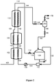
- FIG. 1 a method and apparatus according to one embodiment of the present invention, for liquefying and removing nitrogen from a natural gas stream to produce a nitrogen-depleted LNG product, is shown.
- Natural gas feed stream 100 is first passed through a cooling passage or set of cooling passages in a main heat exchanger to cool, liquefy and (typically) sub-cool the natural gas feed stream, thereby producing a first LNG stream 112.
- the natural gas feed stream comprises methane and nitrogen.
- the natural gas feed stream has nitrogen concentration of from 1 to 10 mol %, and the methods and apparatus described herein can effectively remove nitrogen from the natural gas even where the nitrogen concentration in the natural gas feed stream is relatively low, such as 5 mol % or below.
- the natural gas feed stream should not contain any additional components at concentrations that will freeze in the main heat exchanger during cooling and liquefaction of the stream.
- the natural gas feed stream may be pretreated if and as necessary to remove water, acid gases, mercury and heavy hydrocarbons from the natural gas feed stream, so as to reduce the concentrations of any such components in the natural gas feed stream down to such levels as will not result in any freezing problems.
- Appropriate equipment and techniques for effecting dehydration, acid-gas removal, mercury removal and heavy hydrocarbon removal are well known.
- the natural gas stream must also be at above-ambient pressure, and thus may be compressed and cooled if and as necessary in one or more compressors and aftercoolers (not shown) prior to being introduced into the main heat exchanger.
- the main heat exchanger is composed of three cooling sections in series, namely , a warm section 102 in which the natural gas feed stream 100 is pre-cooled, a middle or intermediate section 106 in which the cooled natural gas feed stream 104 is liquefied, and a cold section 110 in which the liquefied natural gas feed stream 108 is sub-cooled, the end of warm section 102 into which the natural gas feed stream 100 is introduced therefore constituting the warm end of the main heat exchanger, and the end of the cold section 110 from which the first LNG stream 112 is withdrawn therefore constituting the cold end of the main heat exchanger.
- each of these sections constitutes a separate heat exchanger unit having its own shell, casing or other form of housing, but equally two or all three of the sections could be combined into a single heat exchanger unit sharing a common housing.
- the heat exchanger unit(s) may be of any suitable type, such as but not limited to shell and tube, wound coil, or plate and fin types of heat exchanger unit.
- each cooling section will typically comprise its own tube bundle (where the unit is of the shell and tube or wound coil type) or plate and fin bundle (where the unit is of the plate and fin types).
- Some or all of the refrigeration for the main heat exchanger may be provided by any suitable closed loop refrigeration system (not shown).
- Exemplary refrigeration systems that may be used include a single mixed refrigerant (SMR) system, a dual mixed refrigerant (DMR) system, a hybrid propane mixed refrigerant (C3MR) system, a nitrogen expansion cycle (or other gaseous expansion cycle) system, and a cascade refrigeration system.
- SMR single mixed refrigerant
- DMR dual mixed refrigerant
- C3MR hybrid propane mixed refrigerant
- nitrogen expansion cycle or other gaseous expansion cycle
- cascade refrigeration system In the SMR and nitrogen expansion cycle systems, refrigeration is supplied to all three sections 102, 106, 110 of the main heat exchanger by a single mixed refrigerant (in the case of the SMR system) or by nitrogen (in the case of the nitrogen expansion cycle system) circulated by a closed loop refrigeration system.
- two separate closed loop refrigeration systems circulating two separate refrigerants (two different mixed refrigerants in the case of the DMR system, and a propane refrigerant and mixed refrigerant in the case of the C3MR system) are used to supply refrigerant to the main heat exchanger, such that different sections of the main heat exchanger may be cooled by different closed loop systems.
- the operation of SMR, DMR, C3MR, nitrogen expansion cycle and other such closed loop refrigeration systems are well known.
- the first (sub-cooled) LNG stream 112 withdrawn from the cold end of the main heat exchanger is then expanded, partially vaporized and separated to form a nitrogen-depleted (and hence methane enriched) LNG stream 122 and a stripping gas stream 120 composed of nitrogen-enriched natural gas vapor.
- Stream 120 is referred to herein as a stripping gas stream because this stream is used to provide stripping gas to a distillation column, as will be described in further detail below.
- the first LNG stream 112 is expanded, partially vaporized and separated by passing the stream through a J-T (Joule-Thomson) valve 114 into a phase separator 118.
- J-T Joule-Thomson
- any alternative type of expansion device such as a work-extracting device (e.g. hydraulic turbine or turbo expander), and other forms of separation device could equally be used.
- Nitrogen-depleted LNG stream 122 is then further expanded, for example by passing the stream through a J-T valve 124 or turbo-expander (not shown), to form an expanded nitrogen-depleted LNG stream 126 that is introduced into an LNG storage tank 128.
- a portion of the LNG vaporizes, as a result of the initial expansion and introduction of the LNG into the tank and/or as a result ambient heating over time (since the storage tank cannot be perfectly insulated), producing a nitrogen enriched natural gas vapor that collects in and is withdrawn from the headspace of the tank as recycle stream 192, 130, and leaving behind a nitrogen-depleted LNG product that is stored in the tank and can be withdrawn as product stream 196.
- LNG storage tank 128 could be replaced with a phase separator (such as a flash drum) or other form of separation device in which the expanded, nitrogen-depleted LNG stream 122 is separated into liquid a vapor phases forming, respectively, the nitrogen depleted LNG product 196 and recycle stream 192, 130 composed of nitrogen enriched natural gas vapor.
- a phase separator such as a flash drum
- the nitrogen enriched natural gas vapor that collects in and is withdrawn from the headspace of the tank may also be referred to as a tank flash gas (TFG) or boil-off gas (BOG).
- FSG end-flash gas
- the recycle stream 192, 130 composed of nitrogen enriched natural gas vapor is then recompressed in one or more compressors 132 and cooled in one or more aftercoolers 136 to form a compressed recycle stream 138 that is recycled to the main heat exchanger (hence the reason for this stream being referred to as a recycle stream).
- the aftercoolers may use any suitable form of coolant, such as for example water or air at ambient temperature.
- the compressed recycle stream 138, as a result of being cooled in aftercooler(s) 136 is at approximately the same temperature (e.g. ambient) as the natural gas feed stream 100, but it is not added to and mixed with the natural gas feed stream.
- the compressed recycle stream is introduced separately into the warm end of the main heat exchanger and is passed through a separate cooling passage or set of cooling passages, that run parallel to the cooling passages in which the natural gas feed stream is cooled, so as to separately cool the compressed recycle stream in the warm, middle and cold sections 102, 106 and 110 of the main heat exchanger, the compressed recycle stream being cooled and at least partially liquefied to form a first at least partially liquefied (i.e. a partially or fully liquefied) nitrogen-enriched natural gas stream 144.
- the first at least partially liquefied nitrogen-enriched natural gas stream 144 is withdrawn from the cold end of the main heat exchanger, and is then expanded, partially vaporized and introduced into a distillation column 162 in which it is separated into vapor and liquid phases. More specifically, the first at least partially liquefied nitrogen-enriched natural gas stream 144 is expanded, for example through a J-T valve 146 or turbo-expander (not shown), partially vaporized and separated in a phase separator 150 into separate vapor 152 and liquid 172 streams.
- the vapor stream 152 is cooled and at least partially condensed in a heat exchanger 154, further expanded in expansion device (such as J-T valve) 158, and introduced as stream 160 into the distillation column 162 for separation into liquid and vapor phases.
- expansion device such as J-T valve
- the liquid stream 172 is cooled in a reboiler heat exchanger 174, further expanded in expansion device (such as J-T valve) 178, and introduced as stream 180 into the distillation column 162 for separation into liquid and vapor phases.
- the distillation column 162 comprises two separation sections, each composed of inserts such as packing and/or one or more trays to increase contact and thus enhance mass transfer between the upward rising vapor and downward flowing liquid inside the column.
- the cooled and further expanded stream 180 formed from the liquid portion of the first at least partially liquefied nitrogen-enriched natural gas stream 144 is introduced into the distillation column 162 at an intermediate location of the column, between the two separation sections.
- the cooled, at least partially condensed and further expanded vapor stream 160 formed from the vapor portion of the first at least partially liquefied nitrogen-enriched natural gas stream 144 is introduced into the top of distillation column 162, above both separation sections, providing reflux for the column.
- the stripping gas stream 120 separated, as described above, from the first LNG stream 112 in phase separator 118 is also introduced into the distillation column 162, at the bottom of the column, thus providing stripping gas for the column.
- Boil-up, and thus additional stripping gas, for the column is also provided by warming and vaporizing a portion 182 of the bottoms liquid from the column in reboiler heat exchanger 174 (via indirect heat exchange with the liquid portion 172 of the first at least partially liquefied nitrogen-enriched natural gas stream 144) and returning the vaporized bottoms liquid 184 to the bottom of the distillation column.
- the overhead vapor from the distillation column 162 is further enriched in nitrogen (i.e. it is enriched in nitrogen relative to the first at least partially liquefied nitrogen-enriched natural gas stream 144, and thus further enriched in nitrogen relative to the natural gas feed stream 100) and is withdrawn from the top of the distillation column 162 as a nitrogen-rich vapor product stream 164.
- This stream is warmed in heat exchanger 154 (via indirect heat exchange with the vapor portion 152 of the first at least partially liquefied nitrogen-enriched natural gas stream 144) to provide a warmed nitrogen-rich vapor product stream 166 that passes through control valve 169 (which controls the operating pressure of the distillation column) to form the final nitrogen-rich vapor product stream 170.
- a portion 165, 168 of the warmed nitrogen-rich product stream 166 may be recycled by being combined with the recycle stream 192, so as to adjust and maintain a steady nitrogen concentration level in the recycle stream 130, offsetting fluctuations of the natural gas feed composition, the amount of the warmed nitrogen-rich product stream 166 that is recycled being controlled by valve 167.
- the benefit of having stream 165 and the valve 167 is that they enable stable operation of the liquefaction system and the distillation column to be maintained when feed gas composition or flow fluctuates.
- the final nitrogen-rich vapor product stream 170 can be further warmed by heat integration with other refrigerant streams to recover refrigeration (not shown).
- the second LNG stream 186 is then expanded, for example by passing the stream through a J-T valve 188 or turbo-expander (not shown), to form an expanded stream 190 of approximately the same pressure as the expanded nitrogen-depleted LNG stream 126 formed from the first LNG stream 112.
- the expanded second LNG stream is likewise introduced into the LNG storage tank 188 in which, as described above, a portion of the LNG vaporizes, providing nitrogen enriched natural gas vapor that is withdrawn from the headspace of the tank as recycle stream 192, 130, and leaving behind a nitrogen-depleted LNG product that is stored in the tank and can be withdrawn as product stream 196.
- the second LNG stream 186 and the nitrogen-depleted LNG stream 122 formed from the first LNG stream 112 are expanded, combined and together separated into the recycle stream 192, 130 and the LNG product 196.
- the second LNG stream 186 and the nitrogen-depleted LNG stream 122 formed from the first LNG stream 112 could be expanded and introduced into different LNG storage tanks (or other forms of separation system) to produce separate recycle streams that are then combined, and separate LNG product streams.
- the second LNG stream 186 and the nitrogen-depleted LNG stream 122 could (if of or adjusted to a similar pressure) be combined prior to being expanded through a J-T valve, turbo-expander or other form of expansion device, and then the combined expanded stream introduced into the LNG storage tank (or other form of separation system).
- the methane content in the final nitrogen product 170 can reach less than 1 mol %, and the LNG product stored in and withdrawn from in the LNG tank contains less than 1 mol % nitrogen.
- the embodiment therefore provides an simple and efficient means of liquefying natural gas and removing nitrogen to produce both high purity LNG product and a high purity nitrogen stream that can be vented while meeting environmental purity requirements, and without resulting in significant loss of methane.
- the use of the main heat exchanger to cool and at least partially liquefy the recycle stream, in parallel with but separately from the natural gas feed provides distinct advantages.
- the recycle stream is enriched in nitrogen compared to the natural gas feed stream, and so liquefying or partially liquefying this stream separately from the natural gas feed and then separating the resulting at least partially condensed nitrogen-enriched stream provides for a more efficient process of separating the nitrogen and methane components of the recycle stream than if the recycle stream were to be recycled back into and separated together with the natural gas feed stream. Additional benefits of keeping the recycle stream separate from the natural gas feed stream include that the recycle stream does not have to be compressed to the same pressure as the feed, and does not have to go through any natural gas feed pretreatment systems (thus reduce the load on any such systems).
- the recycle stream could be cooled and at least partially liquefied by adding a dedicated heat exchanger and refrigeration system for doing this, using the main heat exchanger and its associated existing refrigeration system to cool and at least partially liquefy the recycle stream, so that this can then be separated into the nitrogen rich product and additional LNG product, provides for a more compact and cost efficient process and apparatus.
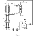
- the comparative method and apparatus depicted in Figure 2 differs from that depicted in Figure 1 in that the first at least partially liquefied nitrogen-enriched natural gas stream 144 withdrawn from the cold end of the main heat exchanger is separated in a phase separator, rather than in a distillation column, into vapor and liquid phases to form the nitrogen rich vapor product and second LNG stream. More specifically, the first at least partially liquefied nitrogen-enriched natural gas stream 144 is expanded, for example through a J-T valve 146 or turbo-expander (not shown), partially vaporized and separated in phase separator 262 to form nitrogen rich vapor product 170 and second LNG stream 186.
- the first at least partially liquefied nitrogen-enriched natural gas stream 144 is separated in a phase separator rather than a distillation column, there is no benefit to generating a stripping gas stream from the first LNG stream 112 withdrawn from the cold end of the main heat exchanger, and accordingly the first LNG stream 112 is expanded, for example by passing the stream through a J-T valve 114 or turbo-expander (not shown), and the expanded nitrogen-depleted LNG stream 116 is introduced directly into the LNG storage tank 128, into which the expanded second LNG stream 190 is also introduced, and from which the nitrogen-depleted LNG product 196 and recycle stream 130 are withdrawn.
- the comparative method and apparatus depicted in Figure 3 differs from that depicted in Figure 1 in that the first at least partially liquefied nitrogen-enriched natural gas stream 144 withdrawn from the cold end of the main heat exchanger is not separated into separate vapor and liquid streams before being introduced into and separated in the distillation column into vapor and liquid phases to form the nitrogen rich vapor product and second LNG stream, and in that no stripping gas is obtained from the first LNG stream 112 withdrawn from the cold end of the main heat exchanger.
- the first at least partially liquefied nitrogen-enriched natural gas stream 144 is cooled in a reboiler heat exchanger 374, expanded and partially vaporized, for example through J-T valve 358 or a turbo-expander (not shown), and introduced as cooled, expanded and partially vaporized stream 360 into distillation column 362 for separation into liquid and vapor phases.
- the distillation column 362 in this case comprises a single separation section.
- the cooled, expanded and partially vaporized stream 360 is introduced into the top of distillation column 162, above the separation section, providing reflux for the column. Boil-up for the column is provided by warming and vaporizing a portion 382 of the bottoms liquid from the column in the reboiler heat exchanger 374.
- the remainder of the bottoms liquid is withdrawn from the bottom of the distillation column forming a second LNG stream 186.
- the first LNG stream 112 and the second LNG stream 186 are expanded, for example by passing the streams through J-T valves 114, 188 or turbo-expanders (not shown), and introduced into the LNG storage tank 128, from which the nitrogen-depleted LNG product 196 and the recycle stream 130 are withdrawn.
- additional or alternative heat sources could be used to supply heat to the reboiler heat exchanger 374.
- an external heat source such as an electric heater
- the comparative method and apparatus depicted in Figure 4 differs from that depicted in Figure 3 in that no reboiler heat exchanger 374 providing boil up to the distillation column 362 is used. Instead, stripping gas for the distillation column 362 is provided by a stream of stripping gas 331 formed from a portion of the cooled compressed recycle stream 142 withdrawn from an intermediate location of the main heat exchanger. More specifically, in the arrangement depicted in Figure 4 the compressed recycle stream 138 is, as before, introduced into the warm end of the main heat exchanger and cooled in the warm 102 and middle 106 sections of the main heat exchanger to form a cooled compressed recycle stream 142 (which preferably at this stage is still at least predominantly all vapor).
- This stream 142 is then divided, with a portion being withdrawn from the main heat exchanger to form the stripping gas stream 331, and the remainder 321 of the stream being further cooled and at least partially liquefied in the cold section 110 of the main heat exchanger to form the first at least partially liquefied nitrogen-enriched natural gas stream 144 that is withdrawn from the cold end of the main heat exchanger.
- the stripping gas stream 331 is then expanded, for example through a J-T valve 332 or a turbo-expander (not shown), and introduced as stream 333 into the bottom of the distillation column 362, thereby providing stripping gas to the column.
- the first at least partially liquefied nitrogen-enriched natural gas stream 144 is expanded and partially vaporized, for example through J-T valve 146 or a turbo-expander (not shown), and introduced as expanded and partially vaporized stream 348 into the top of the distillation column 362, for separation into liquid and vapor phases and thereby providing also reflux for the column.
- a stripping gas for the distillation column for the distillation column could additionally or alternatively be generated from other locations and/or process streams.
- a stripping gas stream could additionally or alternatively be taken: from the cooled compressed recycle stream 140 between the warm 102 and middle 106 sections of the main heat exchanger; form the compressed recycle gas exiting aftercooler 136 (the remainder of said gas then forming the compressed recycle stream 138 that is introduced into the warm end of the main heat exchanger); from the cold natural gas feed stream 108 (if still vapor) between the middle 106 and cold 110 sections of the main heat exchanger; or from the natural gas feed (the remainder of the feed then forming the natural gas feed stream 100 that is introduced into the warm end of the main heat exchanger).
- the comparative method and apparatus depicted in Figure 5 differs from that depicted in Figure 3 in that the distillation column 462 has two separation sections, and the cooled, expanded and partially vaporized stream 360 is introduced into the distillation column 462 at an intermediate location of the column, between the two separation sections.
- Reflux for the distillation column is provided by condensing a portion of the overhead vapor from the distillation column in a condenser heat exchanger. More specifically, the overhead vapor 164 withdrawn from the top of the distillation column 462 is first warmed in condenser heat exchanger 454.
- a portion of the warmed overhead is then compressed in compressor 466, cooled in aftercooler 468 (using coolant such as, for example, air or water at ambient temperature), further cooled and at least partially liquefied in condenser heat exchanger 454, expanded, for example through a J-T valve 476, and returned to the top of distillation column 462 providing reflux.
- the remainder of the warmed overhead forms the nitrogen rich vapor product 170.
- the method and apparatus according to an embodiment of the invention depicted in Figure 6 differs from that depicted in Figure 1 in that the distillation column 562 has one separation section, the first at least partially liquefied nitrogen-enriched natural gas stream 144 withdrawn from the cold end of the main heat exchanger is not separated into separate vapor and liquid streams before being introduced into and separated in the distillation column, and the first LNG stream 112 withdrawn from the cold end of the main heat exchanger is also introduced into and separated in the distillation column.
- the first LNG stream 112 is expanded and partially vaporized, for example by being passed through J-T valve 114 or a turbo-expander (not shown), and is introduced as partially vaporized stream 116 into the bottom of the distillation column 562 for separation into vapor and liquid phases, thereby providing also stripping gas for the column.
- the first at least partially liquefied nitrogen-enriched natural gas stream 144 is expanded and partially vaporized, for example by being passed through J-T valve 146 or a turbo-expander (not shown), and is introduced as partially vaporized stream 148 into the top of the distillation column 562 for separation into vapor and liquid phases, thereby providing also reflux to the column.
- the nitrogen-depleted bottoms liquid is withdrawn from the bottom of the distillation column 562 forming second LNG stream 186 which, as before, is expanded and introduced into the LNG storage tank 128, from which the nitrogen-depleted LNG product 196 and the recycle stream 130 are then withdrawn (the expanded second LNG stream 190 being, in this case, the only LNG stream introduced into the LNG storage tank 128 or other separation system).
- the overhead vapor withdrawn from the top of the distillation column again forms the nitrogen-rich vapor product 170.
- the method and apparatus according to an embodiment of the invention depicted in Figure 7 differs from that depicted in Figure 6 in that the distillation column 662 has two separation sections, the first LNG stream 112 being separated in the distillation column into vapor and liquid phases by being introduced into an intermediate location of the distillation column 662, between the two separation sections. More specifically, the first LNG stream 112 is cooled in reboiler heat exchanger 654, expanded and partially vaporized, for example by being passed through J-T valve 616 or a turbo-expander (not shown), and is introduced as partially vaporized stream 618 into the intermediate location of the distillation column 662.
- the first at least partially liquefied nitrogen-enriched natural gas stream 144 also cooled in reboiler heat exchanger 654 before being expanded and partially vaporized, for example by being passed through J-T valve 658 or a turbo-expander (not shown), and introduced as partially vaporized stream 660 into the top of the distillation column 662.
- Boil-up for the column is provided by warming and vaporizing a portion 682 of the bottoms liquid from the column in the reboiler heat exchanger 654, the remainder of the bottoms liquid being withdrawn from the bottom of the distillation column to form the second LNG stream 186.
- the method and apparatus according to an embodiment of the invention depicted in Figure 8 differs from that depicted in Figure 1 , in that the compressed recycle stream is not introduced into the warm end of the main heat exchanger, but is instead introduced at an intermediate location between cooling sections of the main heat exchanger.
- the main heat exchanger in this case also comprises only two cooling sections.
- the natural gas feed stream 100 is introduced into and cooled in a warm section 706, and the resulting cooled natural gas feed stream 708 is then liquefied and subcooled in a cold section 710 to produce the first LNG stream 112.
- the recycle stream 192 withdrawn from the LNG tank 128 first warmed in an economizer heat exchanger 794, and the warmed recycle stream is then compressed in compressor 732, cooled in aftercooler 736 (against a suitable cooling medium such as, for example, ambient temperature water or air), and then further cooled in the economizer heat exchanger (via heat exchange with the initially withdrawn recycle stream 192) to provide a cooled and compressed recycle stream 740.
- a suitable cooling medium such as, for example, ambient temperature water or air
- This cooled and compressed recycle stream which as a result of cooling in the economizer heat exchanger is at a similar temperature to the cooled natural gas feed stream 708, is introduced into the main heat exchanger at an intermediate location between the two cooling sections, bypassing the warm section 706 of the main heat exchanger and passing through and being cooled and at least partially liquefied in the cold section 710 to provide the first at least partially liquefied nitrogen-enriched natural gas stream 144.
- the method and apparatus depicted according to an embodiment of the invention in Figure 9 differs from that depicted in Figure 6 (and the other previously described embodiments) in that only a portion of the natural gas feed stream is liquefied and withdrawn from the main heat exchanger as the first LNG stream, another portion of the natural gas feed stream being withdrawn as a second at least partially liquefied nitrogen-enriched natural gas stream. More specifically, in embodiment depicted in Figure 9 the liquefied natural gas feed stream 108 withdrawn from the middle or intermediate section 106 of the main heat exchanger is not sent directed to the cold section 110 of the main heat exchanger.
- the stream is expanded and partially vaporized, for example by being passed through J-T valve 850 (or any other suitable expansion device, such as for example a turbo-expander), and introduced into phase separator 854 where it is separated into a nitrogen-enriched natural gas vapor stream 856 and a nitrogen-depleted natural gas liquid stream 858.
- the two streams are then passed through separate cooling passages in the cold section 110 of the main heat exchanger so that the two streams are further cooled, separately but in parallel, so as to form the first LNG stream 112 from the nitrogen-depleted natural gas liquid stream 858 and the second at least partially liquefied nitrogen-enriched natural gas stream 812 from the nitrogen-enriched natural gas vapor stream 856.
- the distillation column 862 in this instance comprises two separation sections.
- the first LNG stream 112 (which in this example has the lowest nitrogen concentration of streams 112, 812 and 144) is expanded and partially vaporized, for example by being passed through J-T valve 114 or a turbo-expander (not shown), and introduced as partially vaporized stream 116 into the bottom of the distillation column 862, thereby providing also stripping gas for the column.
- the second at least partially liquefied nitrogen-enriched natural gas stream 812 is expanded and partially vaporized, for example by being passed through J-T valve 814 or a turbo-expander (not shown), and introduced as partially vaporized stream 816 into an intermediate location of the distillation column 862, between the two separation sections.
- the first at least partially liquefied nitrogen-enriched natural gas stream 144 (which in this example has the highest nitrogen concentration of streams 112, 812 and 144) is cooled in a heat exchanger 846, expanded and partially vaporized, for example by being passed through J-T valve 848 or a turbo-expander (not shown), and introduced as partially vaporized stream 860 into the top of the distillation column 862, thereby providing also reflux for the column.
- the nitrogen-depleted bottoms liquid is withdrawn from the bottom of the distillation column 862, forming second LNG stream 186 which, as before, is expanded and introduced into the LNG storage tank 128, from which the nitrogen-depleted LNG product 196 and the recycle stream 130 are then withdrawn (the expanded second LNG stream 190 being, in this case, the only LNG stream introduced into the LNG storage tank 128 or other separation system).
- the overhead vapor withdrawn from the top of the distillation column again forms a nitrogen-rich vapor product stream 164, which in this case is warmed in heat exchanger 846 (via indirect heat exchange with the first at least partially liquefied nitrogen-enriched natural gas stream 144) to provide a warmed nitrogen-rich vapor product stream 170.
- the nitrogen-rich vapor product stream 164, 170 obtained from the top of the distillation column can be an almost pure nitrogen vapor stream.
- FIG. 10 differs from that depicted in Figure 5 in that in this method and apparatus additional refrigeration for the condenser heat exchanger 454 is provided by a closed loop refrigeration system that provides refrigeration for the main heat exchanger.
- Figure 10 also serves, more generally, to illustrate one possible closed loop refrigeration system that can be used to provide refrigeration to the main heat exchanger in any of the foregoing embodiments of the invention or comparative arrangements.
- refrigeration for the main heat exchanger may, for example, be provided by a single mixed refrigerant (SMR) system.
- the mixed refrigerant that is circulated consists of a mixture of components, such as a mixture of nitrogen, methane, ethane, propane, butane and isopentane.
- each of cooling sections 102, 106 and 110 of the main heat exchanger is, in this example, a heat exchanger unit of the wound coil type. Warmed mixed refrigerant 950 exiting the warm end of the main heat exchanger is compressed in compressor 952 to form a compressed stream 956.
- the compressed stream is then passed through an aftercooler to cool and partly condense the stream, and is then separated in a phase separator into vapor 958 and liquid 906 streams.
- the vapor stream 958 is further compressed in compressor 960 and cooled and partly condensed to form a high pressure mixed refrigerant stream 900 at ambient temperature.
- the aftercoolers can use any suitable ambient heat sink, such as air, freshwater, seawater or water from an evaporative cooling tower.
- the high pressure mixed refrigerant stream 900 is separated in a phase separator into vapor stream 904 and a liquid stream 902.
- Liquid streams 902 and 906 are then subcooled in the warm section 102 of the main heat exchanger, before being reduced in pressure and combined to form cold refrigerant stream 928 which is passed through the shell side of the warm section 102 of the main heat exchanger where it is vaporized and warmed to provide refrigeration to said section.
- Vapor stream 904 is cooled and partly liquefied in the warm section 102 of the main heat exchanger, exiting as stream 908.
- Stream 908 is then separated in a phase separator into vapor stream 912 and liquid stream 910.
- Liquid stream 910 is subcooled in the middle section 106 of the main heat exchanger, and then reduced in pressure form cold refrigerant stream 930 which is passed through the shell side of the middle section 106 of the main heat exchanger where it is vaporized and warmed to provide refrigeration to said section.
- Vapor stream 912 is condensed and subcooled in the middle 106 and cold 110 sections of the main heat exchanger exiting as stream 914.
- Stream 914 is expanded to provide at least cold refrigerant stream 932, which is passed through the shell side of the cold section 110 of the main heat exchanger where it is vaporized and warmed to provide refrigeration to said section.
- the warmed refrigerant (derived from stream 932) exiting the shell side of cold section 110 is combined with refrigerant stream 930 in the shellside of the middle section 106, where it is further warmed and vaporized providing additional refrigerant to that section.
- the combined warmed refrigerant exiting the shell side of middle section 106 is combined with refrigerant stream 928 in the shell side of warm section 102, where it is further warmed and vaporized providing additional refrigerant to that section.
- the combined warmed refrigerant exiting the shell side of the warm section 102 has been fully vaporized and superheated by about 5 °C, and exits as warmed mixed refrigerant stream 950 thus completing the refrigeration loop.
- the closed loop refrigeration system also provides refrigeration for the condenser heat exchanger 454 that condenses a portion 472 of the overhead vapor 164 from the distillation column 462 so as to provide reflux for said column.
- This is achieved by dividing the cooled mixed refrigerant exiting the main heat exchanger and sending a portion of said refrigerant to be warmed in the condenser heat exchanger 454 before being returned to and further warmed in the main heat exchanger. More specifically, mixed refrigerant steam 914 exiting the cold end of the main heat exchanger is divided into two portions, a minor portion 918 (typically less than 10%) and a major portion 916.
- the major portion is expanded to provide the cold refrigerant stream 932 that is used to provide refrigerant to the cold section 110 of the main heat exchanger, as described above.
- the minor portion 918 is expanded, for example by passing the stream through a J-T valve 920 another suitable form of expansion device (such as for example a turbo-expander), to form cold refrigerant stream 922.
- Stream 922 is then warmed and at least partly vaporized in the condenser heat exchanger 454, producing stream 924 that is then returned to the main heat exchanger by being combined with the warmed refrigerant (derived from stream 932) exiting the shell side of cold section 110 and entering the shell side of the middle section 106 with refrigerant stream 930.
- stream 924 could also be directly mixed with stream 930 (not shown).
- the use of the closed loop refrigeration system to provide also refrigeration for the condenser heat exchanger 454 improves the overall efficiency of the process by minimizing the internal temperature differences in the condenser exchanger 454, with the mixed refrigerant providing cooling at the appropriate temperature where the condensation of the recycled nitrogen is occurring.
- This is illustrated by the cooling curves depicted in Figure 11 that are obtained for the condenser heat exchanger 454 when operated in accordance with the arrangement depicted in Figure 10 and described above.
- the discharge pressure of the compressor 466 is chosen such that the compressed and warmed portion of the overhead vapor 472 that is to be cooled in the condenser heat exchanger 454 condenses at a temperature just above the temperature at which the mixed refrigerant vaporizes.
- the overhead vapor 164 withdrawn from the distillation column 462 may enter the condenser heat exchanger 454 at its dew point (about -159 °C), and be warmed to near ambient condition. After withdrawal of the nitrogen-rich vapor product 170, the remaining overhead vapor is then compressed in compressor 466, cooled in aftercooler 468 to near ambient temperature and returned to the condenser heat exchanger 454 to be cooled and condensed, providing reflux for the distillation column 462, as previously described.
- Feed conditions and composition considered Temperature (°F) 91.4 Pressure (psia) 957 Flowrate (lbmol/hr) 4098 Component (mol%) N 2 5.0 C 1 92.0 C 2 1.5 C 3 1.0 nC 4 0.40 nC 5 0.10 Table 2.
Landscapes
- Engineering & Computer Science (AREA)
- Physics & Mathematics (AREA)
- Mechanical Engineering (AREA)
- Thermal Sciences (AREA)
- General Engineering & Computer Science (AREA)
- Chemical & Material Sciences (AREA)
- Oil, Petroleum & Natural Gas (AREA)
- Chemical Kinetics & Catalysis (AREA)
- General Chemical & Material Sciences (AREA)
- Separation By Low-Temperature Treatments (AREA)
Claims (14)
- Procédé de production d'un produit de GNL appauvri en azote, le procédé comprenant :(a) le passage d'un courant d'alimentation en gaz naturel (100) au travers d'un échangeur de chaleur principal (102, 106, 110) pour refroidir le courant d'alimentation en gaz naturel et liquéfier tout ou une portion dudit courant, produisant ainsi un premier courant de GNL (112) ;(b) le retrait du premier courant de GNL (112) de l'échangeur de chaleur principal (102, 106, 110) ;(c) (i) l'expansion, la vaporisation partielle et la séparation du premier courant de GNL (112) pour former un courant de GNL appauvri en azote (122) et un courant de gaz d'extraction composé de vapeur de gaz naturel enrichi en azote (120) ;(c) (ii) l'expansion, la vaporisation partielle et la séparation du courant de GNL appauvri en azote (122) pour former un produit de GNL appauvri en azote (196) et un courant de recyclage composé de vapeur de gaz naturel enrichi en azote (192, 130) ;(d) la compression du courant de recyclage (130) pour former un courant de recyclage compressé (134, 138) ;(e) le passage du courant de recyclage compressé (138) au travers de l'échangeur de chaleur principal (102, 106, 110), séparément et en parallèle du courant d'alimentation en gaz naturel (100), pour refroidir le courant de recyclage compressé et liquéfier au moins partiellement tout ou une portion de celui-ci, produisant ainsi un premier courant de gaz naturel enrichi en azote au moins partiellement liquéfié (144) ;(f) le retrait du premier courant de gaz naturel enrichi en azote au moins partiellement liquéfié (144) de l'échangeur de chaleur principal (102, 106, 110) ; et(g) l'expansion et la vaporisation partielle du premier courant de gaz naturel enrichi en azote au moins partiellement liquéfié (144) et l'introduction dudit courant (148, 160, 180) dans une colonne de distillation (162) pour séparer le courant en phases vapeur et liquide, l'introduction du courant de gaz d'extraction (120, 123) dans le fond de la colonne de distillation (162), et la formation d'un produit de vapeur riche en azote (164, 170) à partir de la vapeur de tête retirée de la colonne de distillation (162).
- Procédé selon la revendication 1, dans lequel l'étape (c) (ii) comprend l'expansion du courant de GNL appauvri en azote (122), le transfert du courant de GNL appauvri en azote expansé (126) dans un réservoir de stockage de GNL (128) dans lequel une portion du GNL se vaporise, formant ainsi une vapeur de gaz naturel enrichi en azote et le produit de GNL appauvri en azote (196), et le retrait de la vapeur de gaz naturel enrichi en azote du réservoir pour former le courant de recyclage (192).
- Procédé de production d'un produit de GNL appauvri en azote, le procédé comprenant :(a) le passage d'un courant d'alimentation en gaz naturel (100) au travers d'un échangeur de chaleur principal (102, 106, 110) pour refroidir le courant d'alimentation en gaz naturel et liquéfier tout ou une portion dudit courant, produisant ainsi un premier courant de GNL (112) ;(b) le retrait du premier courant de GNL (112) de l'échangeur de chaleur principal (102, 106, 110) ;(c) (i) l'expansion et la vaporisation partielle du premier courant de GNL (112) et l'introduction dudit courant (116) dans une colonne de distillation (562) pour séparer le courant en phases vapeur et liquide ;(c) (ii) la formation d'un second courant de GNL (186) du liquide de fond retiré de la colonne de distillation (562) ;(c) (iii) l'expansion, la vaporisation partielle et la séparation du second courant de GNL (186) pour former un produit de GNL appauvri en azote (196) et un courant de recyclage (130) composé de la vapeur de gaz naturel enrichi en azote ;(d) la compression du courant de recyclage (130) pour former un courant de recyclage compressé (134, 138) ;(e) le passage du courant de recyclage compressé (138) au travers de l'échangeur de chaleur principal (102, 106, 110) séparément et en parallèle du courant d'alimentation en gaz naturel (100), pour refroidir le courant de recyclage compressé (138) et liquéfier au moins partiellement tout ou une portion de celui-ci, produisant ainsi un premier courant de gaz naturel enrichi en azote au moins partiellement liquéfié (144) ;(f) le retrait du premier courant de gaz naturel enrichi en azote au moins partiellement liquéfié (144) de l'échangeur de chaleur principal (102, 106, 110) ; et(g) l'expansion et la vaporisation partielle du premier courant de gaz naturel enrichi en azote au moins partiellement liquéfié (144) et l'introduction dudit courant (148) dans la colonne de distillation (562) pour séparer le courant en phases vapeur et liquide, et la formation d'un produit de vapeur riche en azote (164, 170) à partir de la vapeur de tête retirée de la colonne de distillation (562),dans lequel le premier courant de GNL (112, 116) est introduit dans la colonne de distillation (562) à un emplacement sous l'emplacement auquel le premier courant de gaz naturel enrichi en azote au moins partiellement liquéfié (144, 148) est introduit dans la colonne (562).
- Procédé selon la revendication 3, dans lequel l'étape (c) (iii) comprend l'expansion du second courant de GNL (186), le transfert du second courant de GNL expansé (190) dans un réservoir de stockage de GNL (128) dans lequel une portion du GNL se vaporise, formant ainsi une vapeur de gaz naturel enrichi en azote et le produit de GNL appauvri en azote (196), et le retrait de la vapeur de gaz naturel enrichi en azote du réservoir pour former le courant de recyclage (130).
- Procédé selon l'une quelconque des revendications précédentes, dans lequel l'ébullition pour la colonne de distillation (162, 662) est fournie par le chauffage et la vaporisation d'une portion du liquide de fond (182, 682) dans un échangeur de chaleur de rebouilleur (174, 654) via un échange de chaleur indirect avec tout ou une portion du premier courant de gaz naturel enrichi en azote au moins partiellement liquéfié (144, 172) avant l'introduction dudit courant (160, 180, 660) dans la colonne de distillation (162, 662).
- Procédé selon l'une quelconque des revendications précédentes, dans lequel le premier courant de gaz naturel enrichi en azote au moins partiellement liquéfié (144, 148, 160, 180) est introduit dans le dessus de la colonne de distillation (162, 562), ou dans la colonne de distillation (162) à un emplacement intermédiaire de la colonne.
- Procédé selon l'une quelconque des revendications précédentes, dans lequel le premier courant de gaz naturel enrichi en azote au moins partiellement liquéfié (144) est expansé, partiellement vaporisé et séparé en courants séparés de vapeur (152) et liquide (172) avant d'être introduit dans la colonne de distillation (162), le courant liquide (172, 180) étant introduit dans la colonne de distillation (162) à un emplacement intermédiaire, et le courant de vapeur (152) étant refroidi et au moins partiellement condensé dans un échangeur de chaleur de condenseur (154), via l'échange de chaleur indirect avec la vapeur de tête (164) retirée de la colonne (162), et étant ensuite introduit dans le dessus de la colonne (162).
- Procédé selon l'une quelconque des revendications précédentes, dans lequel le procédé comprend en outre le recyclage d'une portion (165) du produit de vapeur riche en azote (164) par ajout de ladite portion (165, 168) au courant de recyclage (192) obtenu à l'étape (c) avant la compression du courant de recyclage (130) à l'étape (d).
- Procédé selon l'une quelconque des revendications précédentes, dans lequel l'échangeur de chaleur principal (102, 106, 110) comprend une extrémité chaude dans laquelle le courant d'alimentation en gaz naturel (100) et le courant de recyclage compressé (138) sont introduits en parallèle, et une extrémité froide de laquelle le premier courant de GNL (112) et le premier courant de gaz naturel enrichi en azote au moins partiellement liquéfié (144) sont retirés en parallèle.
- Procédé selon l'une quelconque des revendications 1 à 9, dans lequel l'échangeur de chaleur principal (706, 710) comprend une extrémité chaude dans laquelle le courant d'alimentation en gaz naturel est introduit (100), et une extrémité froide de laquelle le premier courant de GNL (112) et le premier courant de gaz naturel enrichi en azote au moins partiellement liquéfié (144) sont retirés en parallèle, le courant de recyclage compressé (740) étant introduit dans l'échangeur de chaleur principal (706, 710) à un emplacement intermédiaire entre les extrémités chaude et froide de l'échangeur de chaleur.
- Procédé selon l'une quelconque des revendications précédentes, dans lequel la réfrigération pour l'échangeur de chaleur principal (102, 106, 110) est fournie par un système de réfrigération à boucle fermée, le réfrigérant qui circule par le système de réfrigération à boucle fermée passant au travers et étant chauffé dans l'échangeur de chaleur principal.
- Appareil de production d'un produit de GNL appauvri en azote, l'appareil comprenant :un échangeur de chaleur principal (102, 106, 110) présentant des passages de refroidissement pour la réception d'un courant d'alimentation en gaz naturel (100) et le passage dudit courant au travers de l'échangeur de chaleur pour refroidir le courant et liquéfier tout ou une portion du courant de sorte à produire un premier courant de GNL (112), et pour la réception d'un courant de recyclage compressé (138) composé de vapeur de gaz naturel enrichi en azote et le passage dudit courant au travers de l'échangeur de chaleur pour refroidir et liquéfier au moins partiellement le courant de sorte à produire un premier courant de gaz naturel enrichi en azote au moins partiellement liquéfié (144), dans lequel lesdits passages de refroidissement sont agencés de sorte à faire passer le courant de recyclage compressé au travers de l'échangeur de chaleur séparément et en parallèle du courant d'alimentation en gaz naturel ;un système de réfrigération pour l'alimentation en réfrigérant de l'échangeur de chaleur principal (102, 106, 110) pour le refroidissement des passages de refroidissement ;un premier système de séparation (114, 118), en communication de flux de fluide avec l'échangeur de chaleur principal (102, 106, 110), pour la réception, l'expansion, la vaporisation partielle et la séparation du premier courant de GNL (112) pour former un courant de GNL appauvri en azote (122) et un courant de gaz d'extraction (120) composé de vapeur de gaz naturel enrichi en azote ;un deuxième système de séparation (124, 128), en communication de flux de fluide avec le premier système de séparation (114, 118), pour la réception, l'expansion, la vaporisation partielle et la séparation du courant de GNL appauvri en azote (122) pour former un produit de GNL appauvri en azote (196) et un courant de recyclage composé de vapeur de gaz naturel enrichi en azote (192, 130) ;un compresseur (132), en communication de flux de fluide avec le deuxième système de séparation (124, 128) et l'échangeur de chaleur principal (102, 106, 110), pour la réception du courant de recyclage (130), la compression du courant de recyclage pour former le courant de recyclage compressé (134, 138), et le retour du courant de recyclage compressé à l'échangeur de chaleur principal ; etun troisième système de séparation (146, 158, 178, 162), en communication de flux de fluide avec l'échangeur de chaleur principal (102, 106, 110) et le premier système de séparation (114, 118), pour la réception du courant de gaz d'extraction (120, 123) et pour la réception, l'expansion, la vaporisation partielle et la séparation du premier courant de gaz naturel enrichi en azote au moins partiellement liquéfié (144) pour former un produit de vapeur riche en azote (164, 170), moyennant quoi le troisième système de séparation comprend un dispositif d'expansion (146, 158, 178) pour l'expansion et la vaporisation partielle du premier courant de gaz naturel enrichi en azote au moins partiellement liquéfié (144) et une colonne de distillation (162) pour la séparation dudit courant (160, 180) en phases vapeur et liquide, le courant de gaz d'extraction (120, 123) étant introduit dans le fond de la colonne de distillation (162) et le produit de vapeur riche en azote (164, 170) étant formé à partir de la vapeur de tête retirée de la colonne de distillation (162).
- Appareil de production d'un produit de GNL appauvri en azote, l'appareil comprenant :un échangeur de chaleur principal (102, 106, 110) présentant des passages de refroidissement pour la réception d'un courant d'alimentation en gaz naturel (100) et le passage dudit courant au travers de l'échangeur de chaleur pour refroidir le courant et liquéfier tout ou une portion du courant de sorte à produire un premier courant de GNL (112), et pour la réception d'un courant de recyclage compressé (138) composé de vapeur de gaz naturel enrichi en azote et le passage dudit courant au travers de l'échangeur de chaleur pour refroidir et liquéfier au moins partiellement le courant de sorte à produire un premier courant de gaz naturel enrichi en azote au moins partiellement liquéfié (144), dans lequel lesdits passages de refroidissement sont agencés de sorte à faire passer le courant de recyclage compressé au travers de l'échangeur de chaleur séparément et en parallèle du courant d'alimentation en gaz naturel ;un système de réfrigération pour l'alimentation en réfrigérant de l'échangeur de chaleur principal (102, 106, 110) pour le refroidissement des passages de refroidissement ;un premier système de séparation (146, 114, 562), en communication de flux de fluide avec l'échangeur de chaleur principal (102, 106, 110), pour la réception, l'expansion, la vaporisation partielle et la séparation du premier courant de gaz naturel enrichi en azote au moins partiellement liquéfié (144) pour former un produit de vapeur riche en azote (164, 170) et pour la réception, l'expansion, la vaporisation partielle et la séparation du premier courant de GNL (112) pour former un second courant de GNL (186), moyennant quoi le premier système de séparation comprend un dispositif d'expansion (146) pour l'expansion et la vaporisation partielle du premier courant de gaz naturel enrichi en azote au moins partiellement liquéfié (144), un dispositif d'expansion (114) pour l'expansion et la vaporisation partielle du premier courant de GNL (112), et une colonne de distillation (562) pour la séparation desdits courants (148, 116) en phases vapeur et liquide, moyennant quoi le premier courant de GNL (116) est introduit dans le colonne de distillation (562) à un emplacement sous l'emplacement auquel le premier courant de gaz naturel enrichi en azote au moins partiellement liquéfié (148) est introduit dans la colonne (562), le produit de vapeur riche en azote (164, 170) étant formé à partir de vapeur de tête retirée de la colonne de distillation (562) et le second courant de GNL (186) étant formé à partir de liquide de fond retiré de la colonne de distillation (562) ;un deuxième système de séparation (188, 128), en communication de flux de fluide avec le premier système de séparation (146, 114, 562), pour la réception, l'expansion, la vaporisation partielle et la séparation du second courant de GNL (186) pour former un produit de GNL appauvri en azote (196) et un courant de recyclage (130) composé de vapeur de gaz naturel enrichi en azote ;un compresseur (132), en communication de flux de fluide avec le deuxième système de séparation (188, 128) et l'échangeur de chaleur principal (102, 106, 110), pour la réception du courant de recyclage (130), la compression du courant de recyclage pour former le courant de recyclage compressé (134, 138), et le retour du courant de recyclage compressé (138) à l'échangeur de chaleur principal (102, 106, 110).
- Appareil selon la revendication 12 ou 13, dans lequel le système de réfrigération est un système de réfrigération à boucle fermée, et le deuxième système de séparation comprend un dispositif d'expansion (124, 188) et un réservoir de GNL (128).
Applications Claiming Priority (1)
| Application Number | Priority Date | Filing Date | Title |
|---|---|---|---|
| US14/260,643 US9816754B2 (en) | 2014-04-24 | 2014-04-24 | Integrated nitrogen removal in the production of liquefied natural gas using dedicated reinjection circuit |
Publications (3)
| Publication Number | Publication Date |
|---|---|
| EP2944900A2 EP2944900A2 (fr) | 2015-11-18 |
| EP2944900A3 EP2944900A3 (fr) | 2016-06-08 |
| EP2944900B1 true EP2944900B1 (fr) | 2019-02-27 |
Family
ID=53008336
Family Applications (1)
| Application Number | Title | Priority Date | Filing Date |
|---|---|---|---|
| EP15165001.7A Active EP2944900B1 (fr) | 2014-04-24 | 2015-04-24 | Élimination d'azote intégré dans la production de gaz naturel liquéfié utilisant un circuit de réinjection dédié |
Country Status (11)
| Country | Link |
|---|---|
| US (1) | US9816754B2 (fr) |
| EP (1) | EP2944900B1 (fr) |
| JP (1) | JP6087978B2 (fr) |
| KR (1) | KR101680465B1 (fr) |
| CN (2) | CN204830685U (fr) |
| AU (1) | AU2015201965B2 (fr) |
| BR (1) | BR102015008707B1 (fr) |
| CA (1) | CA2887150C (fr) |
| MY (1) | MY170801A (fr) |
| PE (1) | PE20151709A1 (fr) |
| RU (1) | RU2702074C2 (fr) |
Families Citing this family (17)
| Publication number | Priority date | Publication date | Assignee | Title |
|---|---|---|---|---|
| US9816754B2 (en) * | 2014-04-24 | 2017-11-14 | Air Products And Chemicals, Inc. | Integrated nitrogen removal in the production of liquefied natural gas using dedicated reinjection circuit |
| FR3042984B1 (fr) * | 2015-11-03 | 2019-07-19 | L'air Liquide, Societe Anonyme Pour L'etude Et L'exploitation Des Procedes Georges Claude | Optimisation d’un procede de deazotation d’un courant de gaz naturel |
| FR3042983B1 (fr) * | 2015-11-03 | 2017-10-27 | Air Liquide | Reflux de colonnes de demethanisation |
| CN106883897A (zh) * | 2017-03-29 | 2017-06-23 | 四川华亿石油天然气工程有限公司 | Bog分离提纯设备及工艺 |
| CA2991667A1 (fr) * | 2018-01-11 | 2019-07-11 | 1304338 Alberta Ltd. | Une methode de recuperation du gpl et des condensats des flux de gaz de carburant des rafineries |
| EP3517869A1 (fr) * | 2018-01-24 | 2019-07-31 | Gas Technology Development Pte Ltd | Système et procédé de reliquéfaction de gaz évaporés (bog) |
| CN111433329A (zh) * | 2018-07-24 | 2020-07-17 | 日挥环球株式会社 | 天然气处理装置以及天然气处理方法 |
| US11221176B2 (en) * | 2018-08-14 | 2022-01-11 | Air Products And Chemicals, Inc. | Natural gas liquefaction with integrated nitrogen removal |
| US11186382B2 (en) * | 2018-11-02 | 2021-11-30 | General Electric Company | Fuel oxygen conversion unit |
| WO2021028068A1 (fr) * | 2019-08-13 | 2021-02-18 | Linde Gmbh | Procédé et installation pour traiter un mélange gazeux contenant de l'azote et du méthane |
| US11674749B2 (en) * | 2020-03-13 | 2023-06-13 | Air Products And Chemicals, Inc. | LNG production with nitrogen removal |
| FR3120431B1 (fr) * | 2021-03-05 | 2023-03-31 | Air Liquide | Purification de monoxyde de carbone par distillation cryogénique |
| WO2022239259A1 (fr) * | 2021-05-13 | 2022-11-17 | 株式会社Ihi | Système de refroidissement de gaz |
| CN113566493A (zh) * | 2021-08-06 | 2021-10-29 | 安徽万瑞冷电科技有限公司 | 氦气回收的深冷分离系统 |
| CN114046628B (zh) * | 2022-01-11 | 2022-04-19 | 浙江浙能天然气运行有限公司 | 一种天然气脱氮装置 |
| CN114922705B (zh) * | 2022-04-21 | 2024-03-01 | 西安热工研究院有限公司 | 一种分流再压超临界二氧化碳循环系统及方法 |
| CN115183533A (zh) * | 2022-06-10 | 2022-10-14 | 安徽万瑞冷电科技有限公司 | 一种氦气回收的深冷洗涤分离工艺 |
Family Cites Families (34)
| Publication number | Priority date | Publication date | Assignee | Title |
|---|---|---|---|---|
| DE1551612B1 (de) | 1967-12-27 | 1970-06-18 | Messer Griesheim Gmbh | Verfluessigungsverfahren fuer Gasgemische mittels fraktionierter Kondensation |
| DE1915218B2 (de) | 1969-03-25 | 1973-03-29 | Linde Ag, 6200 Wiesbaden | Verfahren und vorrichtung zum verfluessigen von erdgas |
| US4225329A (en) * | 1979-02-12 | 1980-09-30 | Phillips Petroleum Company | Natural gas liquefaction with nitrogen rejection stabilization |
| US4411677A (en) | 1982-05-10 | 1983-10-25 | Air Products And Chemicals, Inc. | Nitrogen rejection from natural gas |
| US4504295A (en) | 1983-06-01 | 1985-03-12 | Air Products And Chemicals, Inc. | Nitrogen rejection from natural gas integrated with NGL recovery |
| US4710214A (en) * | 1986-12-19 | 1987-12-01 | The M. W. Kellogg Company | Process for separation of hydrocarbon gases |
| US4878932A (en) * | 1989-03-21 | 1989-11-07 | Union Carbide Corporation | Cryogenic rectification process for separating nitrogen and methane |
| US5036671A (en) * | 1990-02-06 | 1991-08-06 | Liquid Air Engineering Company | Method of liquefying natural gas |
| GB2297825A (en) | 1995-02-03 | 1996-08-14 | Air Prod & Chem | Process to remove nitrogen from natural gas |
| MY114649A (en) * | 1998-10-22 | 2002-11-30 | Exxon Production Research Co | A process for separating a multi-component pressurized feed stream using distillation |
| MY117068A (en) * | 1998-10-23 | 2004-04-30 | Exxon Production Research Co | Reliquefaction of pressurized boil-off from pressurized liquid natural gas |
| GB0111961D0 (en) | 2001-05-16 | 2001-07-04 | Boc Group Plc | Nitrogen rejection method |
| US6758060B2 (en) | 2002-02-15 | 2004-07-06 | Chart Inc. | Separating nitrogen from methane in the production of LNG |
| GB0216537D0 (en) * | 2002-07-16 | 2002-08-28 | Boc Group Plc | Nitrogen rejection method and apparatus |
| US6978638B2 (en) | 2003-05-22 | 2005-12-27 | Air Products And Chemicals, Inc. | Nitrogen rejection from condensed natural gas |
| EP1715267A1 (fr) * | 2005-04-22 | 2006-10-25 | Air Products And Chemicals, Inc. | Elimination en deux étapes de l'azote présent dans du gaz naturel liquéfié |
| WO2007021351A1 (fr) | 2005-08-09 | 2007-02-22 | Exxonmobil Upstream Research Company | Procede de liquefaction de gaz naturel destine a produire un gnl |
| WO2007116050A2 (fr) * | 2006-04-12 | 2007-10-18 | Shell Internationale Research Maatschappij B.V. | Procédé et appareil de liquéfaction d'un flux de gaz naturel |
| US9528759B2 (en) | 2008-05-08 | 2016-12-27 | Conocophillips Company | Enhanced nitrogen removal in an LNG facility |
| US20100077796A1 (en) | 2008-09-30 | 2010-04-01 | Sarang Gadre | Hybrid Membrane/Distillation Method and System for Removing Nitrogen from Methane |
| FR2936864B1 (fr) | 2008-10-07 | 2010-11-26 | Technip France | Procede de production de courants d'azote liquide et gazeux, d'un courant gazeux riche en helium et d'un courant d'hydrocarbures deazote et installation associee. |
| US8522574B2 (en) | 2008-12-31 | 2013-09-03 | Kellogg Brown & Root Llc | Method for nitrogen rejection and or helium recovery in an LNG liquefaction plant |
| US8627681B2 (en) * | 2009-03-04 | 2014-01-14 | Lummus Technology Inc. | Nitrogen removal with iso-pressure open refrigeration natural gas liquids recovery |
| DE102009015766A1 (de) | 2009-03-31 | 2010-10-07 | Linde Aktiengesellschaft | Verfahren zum Verflüssigen einer Kohlenwasserstoff-reichen Fraktion |
| DE102009038458A1 (de) * | 2009-08-21 | 2011-02-24 | Linde Ag | Verfahren zum Abtrennen von Stickstoff aus Erdgas |
| GB2462555B (en) | 2009-11-30 | 2011-04-13 | Costain Oil Gas & Process Ltd | Process and apparatus for separation of Nitrogen from LNG |
| US10113127B2 (en) | 2010-04-16 | 2018-10-30 | Black & Veatch Holding Company | Process for separating nitrogen from a natural gas stream with nitrogen stripping in the production of liquefied natural gas |
| KR101704738B1 (ko) | 2010-07-26 | 2017-02-08 | 한국전자통신연구원 | 고해상도 홀로그래픽 디스플레이 |
| DE102011109234A1 (de) | 2011-08-02 | 2013-02-07 | Linde Ag | Verflüssigen eines Methan-reichen Gases |
| JP5679201B2 (ja) | 2011-08-08 | 2015-03-04 | エア・ウォーター株式会社 | ボイルオフガス中の窒素除去方法およびそれに用いる窒素除去装置 |
| RU2607198C2 (ru) | 2011-12-12 | 2017-01-10 | Шелл Интернэшнл Рисерч Маатсхаппий Б.В. | Способ и устройство для удаления азота из криогенной углеводородной композиции |
| CN103998882B (zh) | 2011-12-12 | 2016-04-13 | 国际壳牌研究有限公司 | 用于从低温烃类组合物中去除氮气的方法和装置 |
| US10563913B2 (en) | 2013-11-15 | 2020-02-18 | Black & Veatch Holding Company | Systems and methods for hydrocarbon refrigeration with a mixed refrigerant cycle |
| US9816754B2 (en) * | 2014-04-24 | 2017-11-14 | Air Products And Chemicals, Inc. | Integrated nitrogen removal in the production of liquefied natural gas using dedicated reinjection circuit |
-
2014
- 2014-04-24 US US14/260,643 patent/US9816754B2/en active Active
-
2015
- 2015-04-07 CA CA2887150A patent/CA2887150C/fr active Active
- 2015-04-17 BR BR102015008707-1A patent/BR102015008707B1/pt active IP Right Grant
- 2015-04-20 AU AU2015201965A patent/AU2015201965B2/en active Active
- 2015-04-20 RU RU2015114774A patent/RU2702074C2/ru active
- 2015-04-21 MY MYPI2015701266A patent/MY170801A/en unknown
- 2015-04-22 PE PE2015000531A patent/PE20151709A1/es active IP Right Grant
- 2015-04-24 KR KR1020150058190A patent/KR101680465B1/ko active IP Right Grant
- 2015-04-24 CN CN201520252878.4U patent/CN204830685U/zh active Active
- 2015-04-24 EP EP15165001.7A patent/EP2944900B1/fr active Active
- 2015-04-24 JP JP2015089133A patent/JP6087978B2/ja active Active
- 2015-04-24 CN CN201510198757.0A patent/CN105043014B/zh active Active
Non-Patent Citations (1)
| Title |
|---|
| None * |
Also Published As
| Publication number | Publication date |
|---|---|
| CA2887150A1 (fr) | 2015-10-24 |
| US9816754B2 (en) | 2017-11-14 |
| EP2944900A2 (fr) | 2015-11-18 |
| RU2015114774A3 (fr) | 2018-11-15 |
| CN105043014A (zh) | 2015-11-11 |
| PE20151709A1 (es) | 2015-11-19 |
| CA2887150C (fr) | 2017-07-18 |
| JP2015210078A (ja) | 2015-11-24 |
| RU2702074C2 (ru) | 2019-10-03 |
| CN105043014B (zh) | 2018-03-30 |
| AU2015201965B2 (en) | 2016-05-26 |
| BR102015008707B1 (pt) | 2022-04-19 |
| EP2944900A3 (fr) | 2016-06-08 |
| KR101680465B1 (ko) | 2016-11-28 |
| RU2015114774A (ru) | 2016-11-10 |
| AU2015201965A1 (en) | 2015-11-12 |
| KR20150123192A (ko) | 2015-11-03 |
| US20150308736A1 (en) | 2015-10-29 |
| CN204830685U (zh) | 2015-12-02 |
| MY170801A (en) | 2019-08-28 |
| BR102015008707A2 (pt) | 2016-11-01 |
| JP6087978B2 (ja) | 2017-03-01 |
Similar Documents
| Publication | Publication Date | Title |
|---|---|---|
| EP2944900B1 (fr) | Élimination d'azote intégré dans la production de gaz naturel liquéfié utilisant un circuit de réinjection dédié | |
| US10767922B2 (en) | Integrated nitrogen removal in the production of liquefied natural gas using intermediate feed gas separation | |
| EP2944902B1 (fr) | Élimination d'azote intégré dans la production de gaz naturel liquéfié à l'aide d'une pompe à chaleur réfrigérée | |
| EP3118548B1 (fr) | Méthode et système de réfrigération de méthane intégré pour la liquéfaction de gaz naturel | |
| US20100175423A1 (en) | Methods and apparatus for liquefaction of natural gas and products therefrom | |
| KR102488158B1 (ko) | 질소 제거에 의한 lng 생산 |
Legal Events
| Date | Code | Title | Description |
|---|---|---|---|
| PUAI | Public reference made under article 153(3) epc to a published international application that has entered the european phase |
Free format text: ORIGINAL CODE: 0009012 |
|
| AK | Designated contracting states |
Kind code of ref document: A2 Designated state(s): AL AT BE BG CH CY CZ DE DK EE ES FI FR GB GR HR HU IE IS IT LI LT LU LV MC MK MT NL NO PL PT RO RS SE SI SK SM TR |
|
| AX | Request for extension of the european patent |
Extension state: BA ME |
|
| RIC1 | Information provided on ipc code assigned before grant |
Ipc: F25J 1/00 20060101ALI20151203BHEP Ipc: F25J 1/02 20060101ALI20151203BHEP Ipc: F25J 3/02 20060101AFI20151203BHEP |
|
| PUAL | Search report despatched |
Free format text: ORIGINAL CODE: 0009013 |
|
| AK | Designated contracting states |
Kind code of ref document: A3 Designated state(s): AL AT BE BG CH CY CZ DE DK EE ES FI FR GB GR HR HU IE IS IT LI LT LU LV MC MK MT NL NO PL PT RO RS SE SI SK SM TR |
|
| AX | Request for extension of the european patent |
Extension state: BA ME |
|
| RIC1 | Information provided on ipc code assigned before grant |
Ipc: F25J 1/02 20060101ALI20160503BHEP Ipc: F25J 1/00 20060101ALI20160503BHEP Ipc: F25J 3/02 20060101AFI20160503BHEP |
|
| STAA | Information on the status of an ep patent application or granted ep patent |
Free format text: STATUS: REQUEST FOR EXAMINATION WAS MADE |
|
| 17P | Request for examination filed |
Effective date: 20161208 |
|
| RBV | Designated contracting states (corrected) |
Designated state(s): AL AT BE BG CH CY CZ DE DK EE ES FI FR GB GR HR HU IE IS IT LI LT LU LV MC MK MT NL NO PL PT RO RS SE SI SK SM TR |
|
| STAA | Information on the status of an ep patent application or granted ep patent |
Free format text: STATUS: EXAMINATION IS IN PROGRESS |
|
| 17Q | First examination report despatched |
Effective date: 20180207 |
|
| GRAP | Despatch of communication of intention to grant a patent |
Free format text: ORIGINAL CODE: EPIDOSNIGR1 |
|
| STAA | Information on the status of an ep patent application or granted ep patent |
Free format text: STATUS: GRANT OF PATENT IS INTENDED |
|
| INTG | Intention to grant announced |
Effective date: 20180910 |
|
| RIN1 | Information on inventor provided before grant (corrected) |
Inventor name: CHEN, FEI Inventor name: OTT, CHRISTOPHER MICHAEL Inventor name: KRISHNAMURTHY, GOWRI Inventor name: ROBERTS, MARK JULIAN Inventor name: LIU, YANG |
|
| GRAS | Grant fee paid |
Free format text: ORIGINAL CODE: EPIDOSNIGR3 |
|
| GRAA | (expected) grant |
Free format text: ORIGINAL CODE: 0009210 |
|
| STAA | Information on the status of an ep patent application or granted ep patent |
Free format text: STATUS: THE PATENT HAS BEEN GRANTED |
|
| AK | Designated contracting states |
Kind code of ref document: B1 Designated state(s): AL AT BE BG CH CY CZ DE DK EE ES FI FR GB GR HR HU IE IS IT LI LT LU LV MC MK MT NL NO PL PT RO RS SE SI SK SM TR |
|
| REG | Reference to a national code |
Ref country code: GB Ref legal event code: FG4D |
|
| REG | Reference to a national code |
Ref country code: CH Ref legal event code: EP |
|
| REG | Reference to a national code |
Ref country code: AT Ref legal event code: REF Ref document number: 1101967 Country of ref document: AT Kind code of ref document: T Effective date: 20190315 |
|
| REG | Reference to a national code |
Ref country code: IE Ref legal event code: FG4D |
|
| REG | Reference to a national code |
Ref country code: DE Ref legal event code: R096 Ref document number: 602015025203 Country of ref document: DE |
|
| REG | Reference to a national code |
Ref country code: NL Ref legal event code: FP |
|
| REG | Reference to a national code |
Ref country code: NO Ref legal event code: T2 Effective date: 20190227 |
|
| REG | Reference to a national code |
Ref country code: LT Ref legal event code: MG4D |
|
| PG25 | Lapsed in a contracting state [announced via postgrant information from national office to epo] |
Ref country code: PT Free format text: LAPSE BECAUSE OF FAILURE TO SUBMIT A TRANSLATION OF THE DESCRIPTION OR TO PAY THE FEE WITHIN THE PRESCRIBED TIME-LIMIT Effective date: 20190627 Ref country code: SE Free format text: LAPSE BECAUSE OF FAILURE TO SUBMIT A TRANSLATION OF THE DESCRIPTION OR TO PAY THE FEE WITHIN THE PRESCRIBED TIME-LIMIT Effective date: 20190227 Ref country code: FI Free format text: LAPSE BECAUSE OF FAILURE TO SUBMIT A TRANSLATION OF THE DESCRIPTION OR TO PAY THE FEE WITHIN THE PRESCRIBED TIME-LIMIT Effective date: 20190227 Ref country code: LT Free format text: LAPSE BECAUSE OF FAILURE TO SUBMIT A TRANSLATION OF THE DESCRIPTION OR TO PAY THE FEE WITHIN THE PRESCRIBED TIME-LIMIT Effective date: 20190227 |
|
| PG25 | Lapsed in a contracting state [announced via postgrant information from national office to epo] |
Ref country code: BG Free format text: LAPSE BECAUSE OF FAILURE TO SUBMIT A TRANSLATION OF THE DESCRIPTION OR TO PAY THE FEE WITHIN THE PRESCRIBED TIME-LIMIT Effective date: 20190527 Ref country code: IS Free format text: LAPSE BECAUSE OF FAILURE TO SUBMIT A TRANSLATION OF THE DESCRIPTION OR TO PAY THE FEE WITHIN THE PRESCRIBED TIME-LIMIT Effective date: 20190627 Ref country code: GR Free format text: LAPSE BECAUSE OF FAILURE TO SUBMIT A TRANSLATION OF THE DESCRIPTION OR TO PAY THE FEE WITHIN THE PRESCRIBED TIME-LIMIT Effective date: 20190528 Ref country code: HR Free format text: LAPSE BECAUSE OF FAILURE TO SUBMIT A TRANSLATION OF THE DESCRIPTION OR TO PAY THE FEE WITHIN THE PRESCRIBED TIME-LIMIT Effective date: 20190227 Ref country code: LV Free format text: LAPSE BECAUSE OF FAILURE TO SUBMIT A TRANSLATION OF THE DESCRIPTION OR TO PAY THE FEE WITHIN THE PRESCRIBED TIME-LIMIT Effective date: 20190227 Ref country code: RS Free format text: LAPSE BECAUSE OF FAILURE TO SUBMIT A TRANSLATION OF THE DESCRIPTION OR TO PAY THE FEE WITHIN THE PRESCRIBED TIME-LIMIT Effective date: 20190227 |
|
| REG | Reference to a national code |
Ref country code: AT Ref legal event code: MK05 Ref document number: 1101967 Country of ref document: AT Kind code of ref document: T Effective date: 20190227 |
|
| PG25 | Lapsed in a contracting state [announced via postgrant information from national office to epo] |
Ref country code: RO Free format text: LAPSE BECAUSE OF FAILURE TO SUBMIT A TRANSLATION OF THE DESCRIPTION OR TO PAY THE FEE WITHIN THE PRESCRIBED TIME-LIMIT Effective date: 20190227 Ref country code: IT Free format text: LAPSE BECAUSE OF FAILURE TO SUBMIT A TRANSLATION OF THE DESCRIPTION OR TO PAY THE FEE WITHIN THE PRESCRIBED TIME-LIMIT Effective date: 20190227 Ref country code: ES Free format text: LAPSE BECAUSE OF FAILURE TO SUBMIT A TRANSLATION OF THE DESCRIPTION OR TO PAY THE FEE WITHIN THE PRESCRIBED TIME-LIMIT Effective date: 20190227 Ref country code: CZ Free format text: LAPSE BECAUSE OF FAILURE TO SUBMIT A TRANSLATION OF THE DESCRIPTION OR TO PAY THE FEE WITHIN THE PRESCRIBED TIME-LIMIT Effective date: 20190227 Ref country code: DK Free format text: LAPSE BECAUSE OF FAILURE TO SUBMIT A TRANSLATION OF THE DESCRIPTION OR TO PAY THE FEE WITHIN THE PRESCRIBED TIME-LIMIT Effective date: 20190227 Ref country code: EE Free format text: LAPSE BECAUSE OF FAILURE TO SUBMIT A TRANSLATION OF THE DESCRIPTION OR TO PAY THE FEE WITHIN THE PRESCRIBED TIME-LIMIT Effective date: 20190227 Ref country code: AL Free format text: LAPSE BECAUSE OF FAILURE TO SUBMIT A TRANSLATION OF THE DESCRIPTION OR TO PAY THE FEE WITHIN THE PRESCRIBED TIME-LIMIT Effective date: 20190227 Ref country code: SK Free format text: LAPSE BECAUSE OF FAILURE TO SUBMIT A TRANSLATION OF THE DESCRIPTION OR TO PAY THE FEE WITHIN THE PRESCRIBED TIME-LIMIT Effective date: 20190227 |
|
| REG | Reference to a national code |
Ref country code: DE Ref legal event code: R097 Ref document number: 602015025203 Country of ref document: DE |
|
| PG25 | Lapsed in a contracting state [announced via postgrant information from national office to epo] |
Ref country code: PL Free format text: LAPSE BECAUSE OF FAILURE TO SUBMIT A TRANSLATION OF THE DESCRIPTION OR TO PAY THE FEE WITHIN THE PRESCRIBED TIME-LIMIT Effective date: 20190227 Ref country code: SM Free format text: LAPSE BECAUSE OF FAILURE TO SUBMIT A TRANSLATION OF THE DESCRIPTION OR TO PAY THE FEE WITHIN THE PRESCRIBED TIME-LIMIT Effective date: 20190227 |
|
| REG | Reference to a national code |
Ref country code: CH Ref legal event code: PL |
|
| REG | Reference to a national code |
Ref country code: BE Ref legal event code: MM Effective date: 20190430 |
|
| PG25 | Lapsed in a contracting state [announced via postgrant information from national office to epo] |
Ref country code: LU Free format text: LAPSE BECAUSE OF NON-PAYMENT OF DUE FEES Effective date: 20190424 Ref country code: MC Free format text: LAPSE BECAUSE OF FAILURE TO SUBMIT A TRANSLATION OF THE DESCRIPTION OR TO PAY THE FEE WITHIN THE PRESCRIBED TIME-LIMIT Effective date: 20190227 Ref country code: AT Free format text: LAPSE BECAUSE OF FAILURE TO SUBMIT A TRANSLATION OF THE DESCRIPTION OR TO PAY THE FEE WITHIN THE PRESCRIBED TIME-LIMIT Effective date: 20190227 |
|
| PLBE | No opposition filed within time limit |
Free format text: ORIGINAL CODE: 0009261 |
|
| STAA | Information on the status of an ep patent application or granted ep patent |
Free format text: STATUS: NO OPPOSITION FILED WITHIN TIME LIMIT |
|
| PG25 | Lapsed in a contracting state [announced via postgrant information from national office to epo] |
Ref country code: LI Free format text: LAPSE BECAUSE OF NON-PAYMENT OF DUE FEES Effective date: 20190430 Ref country code: CH Free format text: LAPSE BECAUSE OF NON-PAYMENT OF DUE FEES Effective date: 20190430 |
|
| 26N | No opposition filed |
Effective date: 20191128 |
|
| PG25 | Lapsed in a contracting state [announced via postgrant information from national office to epo] |
Ref country code: SI Free format text: LAPSE BECAUSE OF FAILURE TO SUBMIT A TRANSLATION OF THE DESCRIPTION OR TO PAY THE FEE WITHIN THE PRESCRIBED TIME-LIMIT Effective date: 20190227 Ref country code: BE Free format text: LAPSE BECAUSE OF NON-PAYMENT OF DUE FEES Effective date: 20190430 |
|
| PG25 | Lapsed in a contracting state [announced via postgrant information from national office to epo] |
Ref country code: TR Free format text: LAPSE BECAUSE OF FAILURE TO SUBMIT A TRANSLATION OF THE DESCRIPTION OR TO PAY THE FEE WITHIN THE PRESCRIBED TIME-LIMIT Effective date: 20190227 |
|
| PG25 | Lapsed in a contracting state [announced via postgrant information from national office to epo] |
Ref country code: IE Free format text: LAPSE BECAUSE OF NON-PAYMENT OF DUE FEES Effective date: 20190424 |
|
| PG25 | Lapsed in a contracting state [announced via postgrant information from national office to epo] |
Ref country code: CY Free format text: LAPSE BECAUSE OF FAILURE TO SUBMIT A TRANSLATION OF THE DESCRIPTION OR TO PAY THE FEE WITHIN THE PRESCRIBED TIME-LIMIT Effective date: 20190227 |
|
| PG25 | Lapsed in a contracting state [announced via postgrant information from national office to epo] |
Ref country code: HU Free format text: LAPSE BECAUSE OF FAILURE TO SUBMIT A TRANSLATION OF THE DESCRIPTION OR TO PAY THE FEE WITHIN THE PRESCRIBED TIME-LIMIT; INVALID AB INITIO Effective date: 20150424 Ref country code: MT Free format text: LAPSE BECAUSE OF FAILURE TO SUBMIT A TRANSLATION OF THE DESCRIPTION OR TO PAY THE FEE WITHIN THE PRESCRIBED TIME-LIMIT Effective date: 20190227 |
|
| PG25 | Lapsed in a contracting state [announced via postgrant information from national office to epo] |
Ref country code: MK Free format text: LAPSE BECAUSE OF FAILURE TO SUBMIT A TRANSLATION OF THE DESCRIPTION OR TO PAY THE FEE WITHIN THE PRESCRIBED TIME-LIMIT Effective date: 20190227 |
|
| PGFP | Annual fee paid to national office [announced via postgrant information from national office to epo] |
Ref country code: FR Payment date: 20230309 Year of fee payment: 9 |
|
| P01 | Opt-out of the competence of the unified patent court (upc) registered |
Effective date: 20230515 |
|
| PGFP | Annual fee paid to national office [announced via postgrant information from national office to epo] |
Ref country code: NO Payment date: 20230412 Year of fee payment: 9 Ref country code: DE Payment date: 20230228 Year of fee payment: 9 |
|
| PGFP | Annual fee paid to national office [announced via postgrant information from national office to epo] |
Ref country code: NL Payment date: 20240315 Year of fee payment: 10 |
|
| PGFP | Annual fee paid to national office [announced via postgrant information from national office to epo] |
Ref country code: GB Payment date: 20240229 Year of fee payment: 10 |