EP2944823A1 - Impeller and rotating machine provided with same - Google Patents
Impeller and rotating machine provided with same Download PDFInfo
- Publication number
- EP2944823A1 EP2944823A1 EP15161331.2A EP15161331A EP2944823A1 EP 2944823 A1 EP2944823 A1 EP 2944823A1 EP 15161331 A EP15161331 A EP 15161331A EP 2944823 A1 EP2944823 A1 EP 2944823A1
- Authority
- EP
- European Patent Office
- Prior art keywords
- section
- impeller
- disk
- stress
- axial direction
- Prior art date
- Legal status (The legal status is an assumption and is not a legal conclusion. Google has not performed a legal analysis and makes no representation as to the accuracy of the status listed.)
- Granted
Links
Images






Classifications
-
- F—MECHANICAL ENGINEERING; LIGHTING; HEATING; WEAPONS; BLASTING
- F01—MACHINES OR ENGINES IN GENERAL; ENGINE PLANTS IN GENERAL; STEAM ENGINES
- F01D—NON-POSITIVE DISPLACEMENT MACHINES OR ENGINES, e.g. STEAM TURBINES
- F01D5/00—Blades; Blade-carrying members; Heating, heat-insulating, cooling or antivibration means on the blades or the members
- F01D5/12—Blades
- F01D5/14—Form or construction
- F01D5/141—Shape, i.e. outer, aerodynamic form
-
- F—MECHANICAL ENGINEERING; LIGHTING; HEATING; WEAPONS; BLASTING
- F01—MACHINES OR ENGINES IN GENERAL; ENGINE PLANTS IN GENERAL; STEAM ENGINES
- F01D—NON-POSITIVE DISPLACEMENT MACHINES OR ENGINES, e.g. STEAM TURBINES
- F01D5/00—Blades; Blade-carrying members; Heating, heat-insulating, cooling or antivibration means on the blades or the members
- F01D5/02—Blade-carrying members, e.g. rotors
- F01D5/025—Fixing blade carrying members on shafts
-
- F—MECHANICAL ENGINEERING; LIGHTING; HEATING; WEAPONS; BLASTING
- F04—POSITIVE - DISPLACEMENT MACHINES FOR LIQUIDS; PUMPS FOR LIQUIDS OR ELASTIC FLUIDS
- F04D—NON-POSITIVE-DISPLACEMENT PUMPS
- F04D17/00—Radial-flow pumps, e.g. centrifugal pumps; Helico-centrifugal pumps
- F04D17/08—Centrifugal pumps
- F04D17/10—Centrifugal pumps for compressing or evacuating
- F04D17/12—Multi-stage pumps
-
- F—MECHANICAL ENGINEERING; LIGHTING; HEATING; WEAPONS; BLASTING
- F04—POSITIVE - DISPLACEMENT MACHINES FOR LIQUIDS; PUMPS FOR LIQUIDS OR ELASTIC FLUIDS
- F04D—NON-POSITIVE-DISPLACEMENT PUMPS
- F04D29/00—Details, component parts, or accessories
- F04D29/26—Rotors specially for elastic fluids
- F04D29/266—Rotors specially for elastic fluids mounting compressor rotors on shafts
-
- F—MECHANICAL ENGINEERING; LIGHTING; HEATING; WEAPONS; BLASTING
- F04—POSITIVE - DISPLACEMENT MACHINES FOR LIQUIDS; PUMPS FOR LIQUIDS OR ELASTIC FLUIDS
- F04D—NON-POSITIVE-DISPLACEMENT PUMPS
- F04D29/00—Details, component parts, or accessories
- F04D29/26—Rotors specially for elastic fluids
- F04D29/28—Rotors specially for elastic fluids for centrifugal or helico-centrifugal pumps for radial-flow or helico-centrifugal pumps
- F04D29/284—Rotors specially for elastic fluids for centrifugal or helico-centrifugal pumps for radial-flow or helico-centrifugal pumps for compressors
Definitions
- the present invention relates to an impeller and a rotating machine having a rotary shaft to which the impeller is fixed.
- a rotating machine such as a centrifugal compressor or the like is used.
- the rotating machine has an impeller having a disk section fixed to a rotary shaft and at which a plurality of blades are installed. As the impeller is rotated, pressure energy and velocity energy are applied to a gas.
- Patent Literature 1 In the impeller, when the rotary shaft is rapidly rotated, a tensile stress in the vicinity of an inner circumferential surface of a mounting hole of the impeller may increase and cause damage to the impeller.
- Patent Literature 1 a technology for reducing the tensile stress is disclosed.
- the impeller of Patent Literature 1 has the mounting hole passing through a central section of the impeller.
- the rotary shaft is inserted into the mounting hole by fitting using a slight clearance fit or an interference fit throughout the entire inner circumferential surface. Then, a stress reduction recess configured to reduce the tensile stress is formed at the inner circumferential surface of the mounting hole.
- Fig. 14 is a contour diagram showing a simulation result of a stress applied to an impeller 610 upon high speed rotation.
- the impeller 610 is a so-called open type impeller constituted by a disk section 30 and a blade section 40.
- the disk section 30 includes a tube section 32 to which a grip section (a left section in Fig. 15 ) 33 of a front side in an axis O direction of the rotary shaft 5 is fixed with respect to a rotary shaft 5 by shrinkage fitting or the like, and a disk main body section 35 installed at a position closer to a rear side in the axis O direction than the grip section 33 and extending outward in a radial direction of the rotary shaft 5.
- a point at which the stress applied upon the high speed rotation of the rotary shaft 5 becomes a maximum is in the vicinity of a corner at the rear side in the axis O direction opposite to the grip section 33. This is because the corner of the disk section 30 is to be displaced outward in the radial direction shown by a dotted line of Fig. 15 by a load in a thrust direction (a thrust force) or the like due to a centrifugal force upon rotation or a gas pressure difference between a flow path side and a rear surface side of the disk.
- the stress concentration in the vicinity of the corner is mainly constituted by a hoop stress serving as a tensile stress applied in a circumferential direction of the impeller 610.
- a point at which the hoop stress is concentrated is referred to by reference numeral "f.”
- a magnitude of the hoop stress in the vicinity of the corner of the disk section 30 is increased as a rotational speed is increased, for example, when the rotational speed is unintentionally increased, strength of the disk section 30 may become insufficient.
- a method of fixing the tube section 32 to an outer circumferential surface of the rotary shaft 5 throughout the entire inner circumferential surface of the tube section 32 is considered. Further, a method of fixing the tube section 32 to the outer circumferential surface of the rotary shaft 5 at a plurality of points like Patent Literature 1 is also considered.
- Patent Literature 1 when the impeller 610 is removed from the rotary shaft 5, or the like, an increase in temperature throughout a wide range of the disk section 30 is needed, and ease of assembly and maintenance deteriorate.
- the present invention provides an impeller and a rotating machine provided with the same that are capable of easy attachment and detachment with respect to a rotary shaft and prevention of local concentration of stress upon rotation.
- An impeller includes a tube section having a substantially tube shape, into which a rotary shaft rotated around an axis is inserted, and provided with a grip section installed at one side in an axial direction of the rotary shaft and fixed to the rotary shaft; a disk main body section formed closer to the other side in the axial direction than the grip section and extending from the tube section toward the outside in the radial direction of the rotary shaft; a disk section including the tube section and the disk main body section; and a blade section protruding from the disk main body section to the one side in the axial direction, wherein the disk section includes a hoop stress suppression section extending from the tube section to be closer to the other side in the axial direction than the disk main body section.
- the tube section may include a first axial direction stress displacement groove and a second axial direction stress displacement groove formed on an inner circumferential surface of the tube section or the hoop stress suppression section at both sides in the axial direction of a position at which a hoop stress is concentrated, and configured to displace a position at which an axial direction stress applied to the disk section is concentrated toward the outside in the radial direction from the position at which the hoop stress is concentrated.
- the point at which the axial direction stress is concentrated can be displaced to the outside in the radial direction farther than the first axial direction stress displacement groove and the second axial direction stress displacement groove. Accordingly, since the point at which the axial direction stress is concentrated and the point at which the hoop stress is concentrated can be separated in the radial direction, stress concentration in the disk section can be reduced.
- the disk section may include the hoop stress suppression section as a separate member.
- a rib may be provided throughout the other surface in the axial direction of the disk main body section and the hoop stress suppression section.
- stiffness of a rear surface of the disk section can be improved while suppressing an increase in weight of a rear surface of the disk main body section.
- a rotating machine includes the impeller described above.
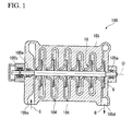
- Fig. 1 is a view showing a schematic configuration of a centrifugal compressor 100, which is the rotating machine of the embodiment.
- a rotary shaft 5 is axially supported at a casing 105 of the centrifugal compressor 100 via a journal bearing 105a and a thrust bearing 105b.
- the rotary shaft 5 can be rotated around an axis O, and a plurality of impellers 10 are attached thereto arranged in the axis O direction.
- the impeller 10 gradually compresses a gas G supplied from a flow path 104 of an upstream side formed at the casing 105 using centrifugal force by rotation of the rotary shaft 5 to cause the gas G to flow to the flow path 104 of a downstream side.
- a suction port 105c configured to introduce the gas G from the outside is formed at the casing 105 at a front side (a left side of Fig. 1 ) in the axis O direction of the rotary shaft 5.
- a discharge port 105d configured to discharge the gas G to the outside is formed at a rear side (a right side of Fig. 1 ) in the axis O direction.
- a left side of the drawings is referred to as a "front side” and a right side of the drawings is referred to as a "rear side.”
- Fig. 1 exemplarily shows six impellers 10 serially installed at the rotary shaft 5, at least one impeller 10 may be installed with respect to the rotary shaft 5. In the following description, for simplicity of description, the case in which one impeller 10 is installed at the rotary shaft 5 is exemplarily described.
- the impeller 10 of the centrifugal compressor 100 includes a disk section 30 fixed with respect to the rotary shaft 5 through shrinkage fitting, and a plurality of blade sections 40 provided to protrude from the front surface 31 in the axis O direction of the disk section 30.
- the impeller 10 of the centrifugal compressor 100 is an open type impeller.
- the disk section 30 includes a tube section 32 fitted onto the rotary shaft 5 and having a substantially cylindrical shape.
- the tube section 32 includes a grip section 33 installed at a front side, which is one side in the axis O direction, and fixed to the outer circumferential surface of the rotary shaft 5, and a non-grip section 34 installed at a rear side, which becomes closer to the other side in the axis O direction than the grip section 33, having a slightly larger diameter than the outer diameter of the rotary shaft 5, and configured to form a gap between the non-grip section 34 and the outer circumferential surface of the rotary shaft 5.
- the grip section 33 has a smaller diameter than the rotary shaft 5 in the state not fixed to the rotary shaft 5, and is fixed to the rotary shaft 5 by shrinkage fitting.
- the disk section 30 includes a disk main body section 35 having a substantially circular plate shape, disposed closer to the other side in the axis O direction than the grip section 33, and extending outward from the non-grip section 34 of the tube section 32 in a radial direction.
- the disk main body section 35 becomes thicker as it goes inward in the radial direction.
- the disk section 30 includes the front surface 31, and a curved surface 31 a having a concave shape and smoothly connected to an outer circumferential surface 32a of the tube section 32.
- the pluralities of blade sections 40 are disposed in the circumferential direction of the disk main body section 35 at equal intervals. These blade sections 40 have a substantially constant plate thickness, and are formed into slightly tapered shape toward the outside in the radial direction when seen in a side view. In addition, these blade sections 40 are formed to protrude from the front surface 31 of the disk section 30 toward a front side in the axis O direction. Further, the above-mentioned flow path 104 is formed by the front surface 31, the curved surface 31a, the outer circumferential surface 32a, surfaces 40a of the blade section 40 opposite to each other in the circumferential direction, and wall surfaces of the casing 105 opposite to the front surface 31 and the curved surface 31 a, at a disposition point of the impeller 10.
- the above-mentioned disk section 30 includes a hoop stress suppression section 50 disposed closer to a rear side opposite to the front side in the axis O direction than the disk main body section 35.
- the hoop stress suppression section 50 is formed to extend from the tube section 32 to the rear side in the axis O direction.
- a position of the rearmost side in the axis O direction of the disk main body section 35 is shown by line C-C.
- a portion formed closer to the rear side in the axis O direction than the line C-C is the hoop stress suppression section 50.
- the hoop stress suppression section 50 has a thickness gradually reduced toward the rear side in the axis O direction to a position at which the thickness becomes a predetermined thickness T1 in the radial direction, from the outside in the radial direction of the disk section 30 toward the inside in the radial direction. Accordingly, the hoop stress suppression section 50 has a rear surface 51 in the axis O direction having a curved surface with a concave shape.
- a length L1 in the axis O direction or the thickness T1 in the radial direction of the hoop stress suppression section 50 may be set to a minimum value of the length L1 or the thickness T1 based on a maximum value of a revolution number of the rotary shaft 5 (a maximum value of the applied hoop stress) and necessary strength of the impeller 10 from a viewpoint of reduction in weight. Further, as the value of the thickness T1 is increased, the maximum value of the hoop stress applied to the impeller 10 is reduced.
- Fig. 3 is a contour diagram showing a simulation result of stress distribution upon high speed rotation in the impeller 10 of the embodiment. Further, in Fig. 3 , the point to which a larger stress is applied is represented with thicker shading (also similar in Fig. 6 ).
- the impeller 10 can be suppressed from being deformed to float in the radial direction at the other side in the axis O direction, and thus an increase in hoop stress caused by deformation in the radial direction of the impeller 10 can be suppressed.
- the dimension of a member in the radial direction of an inclined section 52 between the grip section 33 and the disk main body section 35 may be set to an appropriate dimension of a member in which a sufficient stiffness is obtained in the axis O direction.
- the maximum value of the hoop stress applied to the tube section 32 can be reduced.
- the point fixed to the rotary shaft 5 can be easily attached and detached with respect to the rotary shaft 5 by only fixing the grip section 33 of the front side in the axis O direction, and local concentration of the stress upon rotation can be prevented.
- an impeller 210 according to a second embodiment of the present invention and the impeller 210 will be described with reference to the accompanying drawings.
- the impeller 210 of the second embodiment is distinguished from the impeller 10 of the above-mentioned first embodiment in that a function of separating a hoop stress and an axial direction stress is further provided. For this reason, the same portions as in the above-mentioned first embodiment are designated by the same reference numerals.
- the inner diameter section 32b is curved to float outward from the rotary shaft 5 in the radial direction (shown by a broken line in Fig. 4 ).
- a thrust force from a fluid is applied to the impeller 10.
- an axial direction stress which is a force pulling in both directions which is one side and the other side in the axis O direction, is applied by curved deformation due to the centrifugal force and deformation in the axial direction due to the thrust force.
- axial direction stress is represented by an arrow j.
- deformation of the inner diameter section 32b is exaggerated for clarity.
- the impeller 210 of the second embodiment is an open type impeller having the disk section 30 and the blade section 40, similar to the impeller 10 of the above-mentioned first embodiment.
- the disk section 30 includes the disk main body section 35 and the tube section 32.
- the disk main body section 35 has a substantially circular plate shape extending from the non-grip section 34 toward the outside in the radial direction.
- the disk main body section 35 has a thickness increased as it goes toward the inside in the radial direction.
- the disk section 30 includes the front surface 31, and the curved surface 31 a having a concave shape and configured to be smoothly connected to the outer circumferential surface 32a of the tube section 32.
- the blade section 40 is configured to be similar to the above-mentioned first embodiment, and is formed to protrude from the front surface 31.
- the above-mentioned disk section 30 includes the hoop stress suppression section 50 disposed closer to the rear side in the axis O direction than the disk main body section 35.
- the hoop stress suppression section 50 is formed to extend such that the tube section 32 extends toward the rear side in the axis O direction.
- the tube section 32 and the hoop stress suppression section 50 include a first groove (a first axial direction stress displacement groove) 61 and a second groove (a second axial direction stress displacement groove) 62 formed at inner circumferential surfaces 32c and 50a and having an annular shape about the axis O. That is, the first groove 61 is disposed closer to the rear side in the axis O direction than the line C-C. Further the second groove 62 is spaced a predetermined interval from the first groove 61 and disposed closer to the front side in the axis O direction than the line C-C.
- the centrifugal force upon rotation has a maximum value on or around the line C-C.
- the hoop stress has a maximum stress at a point at which the line C-C and the innermost diameter section of the non-grip section 34 cross each other or therearound.
- the axial direction stress is also generated based on a load in a thrust direction (a thrust force) generated by a gas pressure difference between a flow path side and a disk rear surface side.
- the axial direction stress has a maximum value at the deepest section of the groove, which is a peak of the arc.
- the axial direction stress in the embodiment has a maximum stress in a direction connecting the deepest section 61 a of the first groove 61 and the deepest section 62a of the second groove 62.
- the point at which the axial direction stress is maximized can be displaced outward in the radial direction farther than in the first embodiment.
- the concentrated point of the axial direction stress can be separated from the concentrated point of the hoop stress.
- Fig. 6 is a contour diagram showing a simulation result of stress distribution upon high speed rotation in the impeller 210 of the embodiment.
- the stress applied to the impeller 210 is obtained by overlapping the hoop stress and the axial direction stress. As shown in Fig. 6 , when the concentrated point of the axial direction stress is separated from the concentrated point of the hoop stress (see Fig. 7 ), the maximum value of the stress applied upon rotation is reduced in comparison with the case in which the concentrated points are not separated. In this way, as the first groove 61 and the second groove 62 are formed, the local concentration of the stress upon rotation can be suppressed more than in the impeller 10 of the first embodiment.
- a displacement concept of the impeller 210 upon rotation is shown by a broken line.
- Fig. 5 shows the case in which a groove depth d1 of the first groove 61 is larger than a groove depth d2 of the second groove 62.
- the present invention is not limited to a relative amount of both of the groove depths d1 and d2.
- the present invention is not limited to widths of the first groove 61 and the second groove 62, a distance between the first groove 61 and the second groove 62, or the like. This may be similarly established when separation of the concentrated point of the hoop stress and the concentrated point of the axial direction stress can be set to be significantly performed.
- the groove depth d1 of the first groove 61 and the profile of the second groove 62 may be set such that sufficient strength of the impeller 210 upon rotation can be secured.
- first groove 61 and the second groove 62 have round grooves having an arc-shaped cross-section
- the present invention is not limited thereto.
- a square groove or the like may be used.
- the present invention is not limited thereto.
- a first modified example for example, as shown in Figs. 8A and 8B , this is established even when the first groove 61 and the second groove 62 have asymmetrical shapes with respect to the reference surface perpendicular to the axis O direction (a reference surface D in Fig. 8B ).
- the axial direction stress has a maximum value at a deepest section 61a of the first groove 61 and a deepest section 62a of the second groove 62. This is effective when a groove width is large and the impeller strength upon rotation cannot be sufficiently secured, and particularly, when the concentrated point of the axial direction stress is maximally separated from the concentrated point of the hoop stress.
- the embodiment shows the case in which the first groove 61 is disposed closer to the rear side in the axis O direction than the line C-C, and the second groove 62 is spaced a predetermined interval from the first groove 61 and disposed closer to the front side in the axis O direction than the line C-C.
- this is because the hoop stress is concentrated on the line C-C or therearound.
- the line C-C is disposed at the rearmost side in the axis O direction of the disk main body section 35 and the centrifugal force is in proportion to a radius.
- the concentrated point of the hoop stress may be generated at a point other than the line C-C according to the shape of the impeller and weight distribution in the impeller.
- the first groove 61 may be disposed closer to the rear side than the concentrated point of the hoop stress
- the second groove 62 may be spaced the predetermined interval from the first groove 61 and disposed closer to the front side in the axis O direction than the concentrated point of the hoop stress
- the first groove 61 may be disposed in the axis O direction at one side in the axis O direction of the concentrated point of the hoop stress
- the second groove 62 may be formed at the other side in the axis O direction.
- a hoop stress suppression section 350 may be installed separately with respect to the tube section 32 and the disk main body section 35.
- an annular concave section 37 is formed at a rear surface 36 in the axis O direction of the disk section 30 when seen from the rear side thereof.
- the hoop stress suppression section 350 includes a tubular section 352 fixed to a tubular section 38 inside in the radial direction of the concave section 37 by shrinkage fitting, and a bent section 353 disposed at the rear side in the axis O direction of the tubular section 352 and bent inward in the radial direction.
- a first groove 361 having the same function as the above-mentioned first groove 61 is formed by a front surface 353a of the bent section 353, a rear surface 32d of the tube section 32 and an inner circumferential surface 352a of the tubular section 352.
- a material having a high Young's modulus can be used as a material of the hoop stress suppression section 350, the hoop stress suppression section 350 cannot be easily deformed in comparison with the disk section 30.
- Fig. 9 shows an example in which the corners of the tubular section 352 and the bent section 353 are chamfered to reduce the weight thereof, the chamfering may be omitted.
- the rear surface 51 (see Fig. 2 ) of the hoop stress suppression section 50 may be replaced with ribs 451 radially formed at predetermined intervals when seen from the rear side in the axis O direction.
- the ribs 451 are formed throughout a rear surface 39 in the axis O direction of the disk main body section 35 and the hoop stress suppression section 50.
- a grip section 433 shrinkage-fitted to the rotary shaft 5 may be formed at the rear side as one side in the axis O direction of the disk main body 35.
- a hoop stress suppression section 450 is formed at the front side as the other side in the axis O direction, which becomes an opposite side of the grip section 433 with respect to the disk main body 35.
- the point at which the hoop stress is concentrated is the foremost side in the axis O direction of the disk main body section 35 or therearound.
- the impeller 510 of the fourth modified example includes the hoop stress suppression section 450 disposed at the front side in the axis O direction opposite to the grip section 433 in the axis O direction and having the tube section 33 extending to the front side in the axis O direction, concentration of the hoop stress can be prevented by the hoop stress suppression section 450.
- the first groove 61 and the second groove 62 are formed. As shown in Fig. 13 , as the first groove 61 and the second groove 62 are formed, like the second embodiment, upon rotation, the point at which the hoop stress is concentrated and the point at which the axial direction stress is concentrated are separated, and thus local stress concentration can be suppressed.
- the dimension of a member in a radial direction of the inclined section 451 formed between the grip section 433 and the disk main body section 35 may be set to an appropriate the dimension of a member so that sufficient stiffness is obtained.
- the present invention is not limited thereto.
- the present invention can also be similarly applied to the case in which a plurality of grooves are formed in at least one of the front side and the rear side in the axis O direction.
- the concentrated point of the hoop stress and the concentrated point of the axial direction stress upon rotation can be separated, the local stress concentration can be suppressed, and thus the weight can be further reduced.
- the present invention is not limited thereto.
- the grip section may be formed at at least one side in the axis O direction to be fixed to the outer circumferential surface of the rotary shaft 5.
- a fixing method using thermal deformation including also shrinkage fitting or freeze fitting is appropriate for the present invention due to easy attachment and detachment by heating or cooling.
- the present invention is not limited thereto.
- the present invention can also be applied to a closed type impeller further having a portion of a cover with respect to the disk section 30 and the blade section 40.
- the present invention is not limited to the centrifugal compressor 100, and for example, the impeller of the present invention can also be applied to various industrial compressors, turbo freezing machines, and small gas turbines.
Landscapes
- Engineering & Computer Science (AREA)
- Mechanical Engineering (AREA)
- General Engineering & Computer Science (AREA)
- Physics & Mathematics (AREA)
- Fluid Mechanics (AREA)
- Structures Of Non-Positive Displacement Pumps (AREA)
Abstract
Description
- The present invention relates to an impeller and a rotating machine having a rotary shaft to which the impeller is fixed.
- Priority is claimed on Japanese Patent Application No.
2012-028763, filed February 13, 2012 - In a turbo freezing machine, a small gas turbine, or the like, a rotating machine such as a centrifugal compressor or the like is used. The rotating machine has an impeller having a disk section fixed to a rotary shaft and at which a plurality of blades are installed. As the impeller is rotated, pressure energy and velocity energy are applied to a gas.
- In the impeller, when the rotary shaft is rapidly rotated, a tensile stress in the vicinity of an inner circumferential surface of a mounting hole of the impeller may increase and cause damage to the impeller. In order to prevent damage to the impeller, in Patent Literature 1, a technology for reducing the tensile stress is disclosed. The impeller of Patent Literature 1 has the mounting hole passing through a central section of the impeller. The rotary shaft is inserted into the mounting hole by fitting using a slight clearance fit or an interference fit throughout the entire inner circumferential surface. Then, a stress reduction recess configured to reduce the tensile stress is formed at the inner circumferential surface of the mounting hole.
-
- [Patent Literature 1] Japanese Unexamined Patent Application, First Publication No.
2005-002849 -
Fig. 14 is a contour diagram showing a simulation result of a stress applied to animpeller 610 upon high speed rotation. Theimpeller 610 is a so-called open type impeller constituted by adisk section 30 and ablade section 40. Referring toFig. 15 , thedisk section 30 includes atube section 32 to which a grip section (a left section inFig. 15 ) 33 of a front side in an axis O direction of therotary shaft 5 is fixed with respect to arotary shaft 5 by shrinkage fitting or the like, and a diskmain body section 35 installed at a position closer to a rear side in the axis O direction than thegrip section 33 and extending outward in a radial direction of therotary shaft 5. In theimpeller 610 formed as described above, a point at which the stress applied upon the high speed rotation of therotary shaft 5 becomes a maximum (a stress concentration point) is in the vicinity of a corner at the rear side in the axis O direction opposite to thegrip section 33. This is because the corner of thedisk section 30 is to be displaced outward in the radial direction shown by a dotted line ofFig. 15 by a load in a thrust direction (a thrust force) or the like due to a centrifugal force upon rotation or a gas pressure difference between a flow path side and a rear surface side of the disk. The stress concentration in the vicinity of the corner is mainly constituted by a hoop stress serving as a tensile stress applied in a circumferential direction of theimpeller 610. In addition, inFig. 15 , a point at which the hoop stress is concentrated is referred to by reference numeral "f." - Since a magnitude of the hoop stress in the vicinity of the corner of the
disk section 30 is increased as a rotational speed is increased, for example, when the rotational speed is unintentionally increased, strength of thedisk section 30 may become insufficient. In order to prevent the insufficient strength, for example, a method of fixing thetube section 32 to an outer circumferential surface of therotary shaft 5 throughout the entire inner circumferential surface of thetube section 32 is considered. Further, a method of fixing thetube section 32 to the outer circumferential surface of therotary shaft 5 at a plurality of points like Patent Literature 1 is also considered. However, when theimpeller 610 is removed from therotary shaft 5, or the like, an increase in temperature throughout a wide range of thedisk section 30 is needed, and ease of assembly and maintenance deteriorate. - In consideration of the above-mentioned circumstances, the present invention provides an impeller and a rotating machine provided with the same that are capable of easy attachment and detachment with respect to a rotary shaft and prevention of local concentration of stress upon rotation.
- In order to solve the above-mentioned problems, the following configurations are employed.
- An impeller according to a first aspect of the present invention includes a tube section having a substantially tube shape, into which a rotary shaft rotated around an axis is inserted, and provided with a grip section installed at one side in an axial direction of the rotary shaft and fixed to the rotary shaft; a disk main body section formed closer to the other side in the axial direction than the grip section and extending from the tube section toward the outside in the radial direction of the rotary shaft; a disk section including the tube section and the disk main body section; and a blade section protruding from the disk main body section to the one side in the axial direction, wherein the disk section includes a hoop stress suppression section extending from the tube section to be closer to the other side in the axial direction than the disk main body section.
- In this way, by only fixing the grip section of the one side in the axial direction, easy attachment and detachment with respect to the rotary shaft can be performed. Meanwhile, in the other side in the axial direction not fixed to the rotary shaft, as stiffness of deformation in the radial direction by the centrifugal force is increased by the hoop stress suppression section extending to the other side in the axial direction, the impeller can be suppressed from being deformed to float in the radial direction at the other side in the axial direction. Accordingly, an increase in hoop stress generated by deformation in the radial direction can be suppressed.
- In the impeller, the tube section may include a first axial direction stress displacement groove and a second axial direction stress displacement groove formed on an inner circumferential surface of the tube section or the hoop stress suppression section at both sides in the axial direction of a position at which a hoop stress is concentrated, and configured to displace a position at which an axial direction stress applied to the disk section is concentrated toward the outside in the radial direction from the position at which the hoop stress is concentrated.
- As a result, the point at which the axial direction stress is concentrated can be displaced to the outside in the radial direction farther than the first axial direction stress displacement groove and the second axial direction stress displacement groove. Accordingly, since the point at which the axial direction stress is concentrated and the point at which the hoop stress is concentrated can be separated in the radial direction, stress concentration in the disk section can be reduced.
- In the impeller, the disk section may include the hoop stress suppression section as a separate member.
- As a result, since a material having a higher Young's modulus than the disk section can be employed as a material of the hoop stress suppression section, it is more difficult to be deformed the hoop stress suppression section.
- In the impeller, a rib may be provided throughout the other surface in the axial direction of the disk main body section and the hoop stress suppression section.
- According to the above-mentioned configuration, stiffness of a rear surface of the disk section can be improved while suppressing an increase in weight of a rear surface of the disk main body section.
- A rotating machine according to a second aspect of the present invention includes the impeller described above.
- According to the above-mentioned configuration, maintenance of the impeller can be improved. Further, since damage to the impeller upon rotation can be prevented, reliability can be improved.
- According to the present invention, easy attachment and detachment with respect to the rotary shaft and prevention of local concentration of a stress upon rotation become possible.
-
-
Fig. 1 is a longitudinal cross-sectional view of a centrifugal compressor according to an embodiment of the present invention. -
Fig. 2 is a longitudinal cross-sectional view of an impeller according to a first embodiment of the present invention. -
Fig. 3 is a view showing a simulation result of the impeller. -
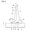
Fig. 4 is a view for describing a hoop stress and an axial direction stress of the impeller. -
Fig. 5 is a longitudinal cross-sectional view corresponding toFig. 2 according to a second embodiment of the present invention. -
Fig. 6 is a view showing a simulation result of the impeller. -
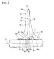
Fig. 7 is a view for describing a hoop stress and an axial direction stress of the impeller. -
Fig. 8A is a longitudinal cross-sectional view corresponding toFig. 2 according to a first modified example of the second embodiment. -
Fig. 8B is a partially enlarged view ofFig. 8A . -
Fig. 9 is a longitudinal cross-sectional view corresponding toFig. 2 according to a second modified example of the second embodiment. -
Fig. 10 is a longitudinal cross-sectional view corresponding toFig. 2 according to a third modified example of the second embodiment. -
Fig. 11 is a side view when seen from a rear side in an axial direction of the third modified example. -
Fig. 12 is a longitudinal cross-sectional view corresponding toFig. 2 according to a fourth modified example of the second embodiment. -
Fig. 13 is a view for describing the impeller corresponding toFig. 7 according to the fourth modified example. -
Fig. 14 is a view corresponding toFig. 3 of an impeller of the related art. -
Fig. 15 is a view for describing a hoop stress in the impeller of the related art. - A rotating machine and an impeller according to a first embodiment of the present invention will be described with reference to the accompanying drawings.
-
Fig. 1 is a view showing a schematic configuration of acentrifugal compressor 100, which is the rotating machine of the embodiment. - As shown in
Fig. 1 , arotary shaft 5 is axially supported at acasing 105 of thecentrifugal compressor 100 via a journal bearing 105a and athrust bearing 105b. Therotary shaft 5 can be rotated around an axis O, and a plurality ofimpellers 10 are attached thereto arranged in the axis O direction. - The
impeller 10 gradually compresses a gas G supplied from aflow path 104 of an upstream side formed at thecasing 105 using centrifugal force by rotation of therotary shaft 5 to cause the gas G to flow to theflow path 104 of a downstream side. - A
suction port 105c configured to introduce the gas G from the outside is formed at thecasing 105 at a front side (a left side ofFig. 1 ) in the axis O direction of therotary shaft 5. In addition, adischarge port 105d configured to discharge the gas G to the outside is formed at a rear side (a right side ofFig. 1 ) in the axis O direction. In addition, in the following description, a left side of the drawings is referred to as a "front side" and a right side of the drawings is referred to as a "rear side." - When the
rotary shaft 5 is rotated by the configuration of thecentrifugal compressor 100, the gas G from thesuction port 105c is introduced into theflow path 104, and the gas G is gradually compressed by theimpeller 10 and then discharged from thedischarge port 105d. Further, whileFig. 1 exemplarily shows siximpellers 10 serially installed at therotary shaft 5, at least oneimpeller 10 may be installed with respect to therotary shaft 5. In the following description, for simplicity of description, the case in which oneimpeller 10 is installed at therotary shaft 5 is exemplarily described. - As shown in
Fig. 2 , theimpeller 10 of thecentrifugal compressor 100 includes adisk section 30 fixed with respect to therotary shaft 5 through shrinkage fitting, and a plurality ofblade sections 40 provided to protrude from thefront surface 31 in the axis O direction of thedisk section 30. Theimpeller 10 of thecentrifugal compressor 100 is an open type impeller. - The
disk section 30 includes atube section 32 fitted onto therotary shaft 5 and having a substantially cylindrical shape. Thetube section 32 includes agrip section 33 installed at a front side, which is one side in the axis O direction, and fixed to the outer circumferential surface of therotary shaft 5, and anon-grip section 34 installed at a rear side, which becomes closer to the other side in the axis O direction than thegrip section 33, having a slightly larger diameter than the outer diameter of therotary shaft 5, and configured to form a gap between thenon-grip section 34 and the outer circumferential surface of therotary shaft 5. Thegrip section 33 has a smaller diameter than therotary shaft 5 in the state not fixed to therotary shaft 5, and is fixed to therotary shaft 5 by shrinkage fitting. - Further, the
disk section 30 includes a diskmain body section 35 having a substantially circular plate shape, disposed closer to the other side in the axis O direction than thegrip section 33, and extending outward from thenon-grip section 34 of thetube section 32 in a radial direction. - The disk
main body section 35 becomes thicker as it goes inward in the radial direction. In addition, thedisk section 30 includes thefront surface 31, and acurved surface 31 a having a concave shape and smoothly connected to an outercircumferential surface 32a of thetube section 32. - The pluralities of
blade sections 40 are disposed in the circumferential direction of the diskmain body section 35 at equal intervals. Theseblade sections 40 have a substantially constant plate thickness, and are formed into slightly tapered shape toward the outside in the radial direction when seen in a side view. In addition, theseblade sections 40 are formed to protrude from thefront surface 31 of thedisk section 30 toward a front side in the axis O direction. Further, the above-mentionedflow path 104 is formed by thefront surface 31, thecurved surface 31a, the outercircumferential surface 32a, surfaces 40a of theblade section 40 opposite to each other in the circumferential direction, and wall surfaces of thecasing 105 opposite to thefront surface 31 and thecurved surface 31 a, at a disposition point of theimpeller 10. - The above-mentioned
disk section 30 includes a hoopstress suppression section 50 disposed closer to a rear side opposite to the front side in the axis O direction than the diskmain body section 35. The hoopstress suppression section 50 is formed to extend from thetube section 32 to the rear side in the axis O direction. Here, inFig. 3 , a position of the rearmost side in the axis O direction of the diskmain body section 35 is shown by line C-C. A portion formed closer to the rear side in the axis O direction than the line C-C is the hoopstress suppression section 50. - The hoop
stress suppression section 50 has a thickness gradually reduced toward the rear side in the axis O direction to a position at which the thickness becomes a predetermined thickness T1 in the radial direction, from the outside in the radial direction of thedisk section 30 toward the inside in the radial direction. Accordingly, the hoopstress suppression section 50 has arear surface 51 in the axis O direction having a curved surface with a concave shape. Here, a length L1 in the axis O direction or the thickness T1 in the radial direction of the hoopstress suppression section 50 may be set to a minimum value of the length L1 or the thickness T1 based on a maximum value of a revolution number of the rotary shaft 5 (a maximum value of the applied hoop stress) and necessary strength of theimpeller 10 from a viewpoint of reduction in weight. Further, as the value of the thickness T1 is increased, the maximum value of the hoop stress applied to theimpeller 10 is reduced. -
Fig. 3 is a contour diagram showing a simulation result of stress distribution upon high speed rotation in theimpeller 10 of the embodiment. Further, inFig. 3 , the point to which a larger stress is applied is represented with thicker shading (also similar inFig. 6 ). - As shown in
Fig. 3 , in the case of theimpeller 10 including the hoopstress suppression section 50, a range in which the stress applied upon rotation extends in the axis O direction than in the case of an impeller (seeFig. 14 ) that does not include the hoopstress suppression section 50. However, the maximum value thereof is reduced. - This is because, as stiffness of the
tube section 32 in the radial direction due to a centrifugal force is increased by the hoopstress suppression section 50, theimpeller 10 can be suppressed from being deformed to float in the radial direction at the other side in the axis O direction, and thus an increase in hoop stress caused by deformation in the radial direction of theimpeller 10 can be suppressed. - In addition, in the
impeller 10, the dimension of a member in the radial direction of aninclined section 52 between thegrip section 33 and the diskmain body section 35 may be set to an appropriate dimension of a member in which a sufficient stiffness is obtained in the axis O direction. As a result, even at the front side opposite to the hoopstress suppression section 50 in the axis O direction in which thegrip section 33 is installed, deformation in the radial direction of thetube section 32 can be suppressed, and it is possible to contribute to reduction in hoop stress. - Accordingly, according to the impeller of the above-mentioned first embodiment, the maximum value of the hoop stress applied to the
tube section 32 can be reduced. As a result, the point fixed to therotary shaft 5 can be easily attached and detached with respect to therotary shaft 5 by only fixing thegrip section 33 of the front side in the axis O direction, and local concentration of the stress upon rotation can be prevented. - Next, an
impeller 210 according to a second embodiment of the present invention and theimpeller 210 will be described with reference to the accompanying drawings. Note that, theimpeller 210 of the second embodiment is distinguished from theimpeller 10 of the above-mentioned first embodiment in that a function of separating a hoop stress and an axial direction stress is further provided. For this reason, the same portions as in the above-mentioned first embodiment are designated by the same reference numerals. - First, based on
Fig. 4 , a hoop stress and an axial direction stress applied to theimpeller 10 of the above-mentioned first embodiment will be described. - As shown in
Fig. 4 , in theimpeller 10, while the hoop stress is evenly distributed by the hoopstress suppression section 50, the hoop stress is concentrated on aninner diameter section 32b of the diskmain body section 35 disposed inside in the radial direction. Further, inFig. 4 , a point at which the hoop stress is maximally concentrated is referred to by reference numeral "f." - Further, even in the
impeller 10, upon rotation of therotary shaft 5, since theinner diameter section 32b is to be displaced outward in a centrifugal direction (the radial direction), theinner diameter section 32b is curved to float outward from therotary shaft 5 in the radial direction (shown by a broken line inFig. 4 ). In addition, a thrust force from a fluid is applied to theimpeller 10. Then, an axial direction stress, which is a force pulling in both directions which is one side and the other side in the axis O direction, is applied by curved deformation due to the centrifugal force and deformation in the axial direction due to the thrust force. - Then, stress concentration occurs due to overlapping of the stress in the axis O direction and the hoop stress.
- Further, in
Fig. 4 , the axial direction stress is represented by an arrow j. In addition, inFig. 4 , deformation of theinner diameter section 32b is exaggerated for clarity. - As shown in
Fig. 5 , theimpeller 210 of the second embodiment is an open type impeller having thedisk section 30 and theblade section 40, similar to theimpeller 10 of the above-mentioned first embodiment. Thedisk section 30 includes the diskmain body section 35 and thetube section 32. - The disk
main body section 35 has a substantially circular plate shape extending from thenon-grip section 34 toward the outside in the radial direction. The diskmain body section 35 has a thickness increased as it goes toward the inside in the radial direction. In addition, thedisk section 30 includes thefront surface 31, and thecurved surface 31 a having a concave shape and configured to be smoothly connected to the outercircumferential surface 32a of thetube section 32. Theblade section 40 is configured to be similar to the above-mentioned first embodiment, and is formed to protrude from thefront surface 31. - The above-mentioned
disk section 30 includes the hoopstress suppression section 50 disposed closer to the rear side in the axis O direction than the diskmain body section 35. The hoopstress suppression section 50 is formed to extend such that thetube section 32 extends toward the rear side in the axis O direction. - In addition, the
tube section 32 and the hoopstress suppression section 50 include a first groove (a first axial direction stress displacement groove) 61 and a second groove (a second axial direction stress displacement groove) 62 formed at innercircumferential surfaces first groove 61 is disposed closer to the rear side in the axis O direction than the line C-C. Further thesecond groove 62 is spaced a predetermined interval from thefirst groove 61 and disposed closer to the front side in the axis O direction than the line C-C. - In general, the centrifugal force upon rotation has a maximum value on or around the line C-C. For this reason, as shown in
Fig. 4 , the hoop stress has a maximum stress at a point at which the line C-C and the innermost diameter section of thenon-grip section 34 cross each other or therearound. Further upon rotation, the axial direction stress is also generated based on a load in a thrust direction (a thrust force) generated by a gas pressure difference between a flow path side and a disk rear surface side. When the grooves (thefirst groove 61 and the second groove 62) are formed like in the embodiment, the thrust force has a high value around the groove. For example, when a portion of the groove is a round groove having an arc shape like in the embodiment, the axial direction stress has a maximum value at the deepest section of the groove, which is a peak of the arc. For this reason, the axial direction stress in the embodiment has a maximum stress in a direction connecting thedeepest section 61 a of thefirst groove 61 and thedeepest section 62a of thesecond groove 62. In this way, as thefirst groove 61 and thesecond groove 62 are formed, the point at which the axial direction stress is maximized can be displaced outward in the radial direction farther than in the first embodiment. As a result, the concentrated point of the axial direction stress can be separated from the concentrated point of the hoop stress. -
Fig. 6 is a contour diagram showing a simulation result of stress distribution upon high speed rotation in theimpeller 210 of the embodiment. - The stress applied to the
impeller 210 is obtained by overlapping the hoop stress and the axial direction stress. As shown inFig. 6 , when the concentrated point of the axial direction stress is separated from the concentrated point of the hoop stress (seeFig. 7 ), the maximum value of the stress applied upon rotation is reduced in comparison with the case in which the concentrated points are not separated. In this way, as thefirst groove 61 and thesecond groove 62 are formed, the local concentration of the stress upon rotation can be suppressed more than in theimpeller 10 of the first embodiment. - As a result, the stress concentration in the
disk section 30 can be reduced, and especially, deformation upon high speed rotation of theimpeller 210 can be suppressed. InFig. 7 , a displacement concept of theimpeller 210 upon rotation is shown by a broken line. - Further,
Fig. 5 shows the case in which a groove depth d1 of thefirst groove 61 is larger than a groove depth d2 of thesecond groove 62. However, the present invention is not limited to a relative amount of both of the groove depths d1 and d2. In addition, the present invention is not limited to widths of thefirst groove 61 and thesecond groove 62, a distance between thefirst groove 61 and thesecond groove 62, or the like. This may be similarly established when separation of the concentrated point of the hoop stress and the concentrated point of the axial direction stress can be set to be significantly performed. The groove depth d1 of thefirst groove 61 and the profile of thesecond groove 62 may be set such that sufficient strength of theimpeller 210 upon rotation can be secured. - In addition, in the embodiment, while the case in which portions of the
first groove 61 and thesecond groove 62 have round grooves having an arc-shaped cross-section has been described, the present invention is not limited thereto. For example, a square groove or the like may be used. - In addition, while the case in which the
first groove 61 and thesecond groove 62 have symmetrical shapes with respect to a reference surface perpendicular to the axis O direction has been shown, the present invention is not limited thereto. As a first modified example, for example, as shown inFigs. 8A and 8B , this is established even when thefirst groove 61 and thesecond groove 62 have asymmetrical shapes with respect to the reference surface perpendicular to the axis O direction (a reference surface D inFig. 8B ). Even in this case, the axial direction stress has a maximum value at adeepest section 61a of thefirst groove 61 and adeepest section 62a of thesecond groove 62. This is effective when a groove width is large and the impeller strength upon rotation cannot be sufficiently secured, and particularly, when the concentrated point of the axial direction stress is maximally separated from the concentrated point of the hoop stress. - Further, the embodiment shows the case in which the
first groove 61 is disposed closer to the rear side in the axis O direction than the line C-C, and thesecond groove 62 is spaced a predetermined interval from thefirst groove 61 and disposed closer to the front side in the axis O direction than the line C-C. In general, this is because the hoop stress is concentrated on the line C-C or therearound. This is because the line C-C is disposed at the rearmost side in the axis O direction of the diskmain body section 35 and the centrifugal force is in proportion to a radius. However, the concentrated point of the hoop stress may be generated at a point other than the line C-C according to the shape of the impeller and weight distribution in the impeller. In this case, regardless of the position of the line C-C, thefirst groove 61 may be disposed closer to the rear side than the concentrated point of the hoop stress, thesecond groove 62 may be spaced the predetermined interval from thefirst groove 61 and disposed closer to the front side in the axis O direction than the concentrated point of the hoop stress, and in the inner circumferential surface continuing to at least thetube section 32 and the hoopstress suppression section 50, thefirst groove 61 may be disposed in the axis O direction at one side in the axis O direction of the concentrated point of the hoop stress and thesecond groove 62 may be formed at the other side in the axis O direction. - Further, the present invention is not limited to the configuration of the above-mentioned embodiment, and design changes may be made without departing from the scope of the present invention.
- For example, as a second modified example of the above-mentioned second embodiment, like an
impeller 310 shown inFig. 9 , a hoopstress suppression section 350 may be installed separately with respect to thetube section 32 and the diskmain body section 35. In the case of the second modified example shown inFig. 9 , an annularconcave section 37 is formed at arear surface 36 in the axis O direction of thedisk section 30 when seen from the rear side thereof. Here, the hoopstress suppression section 350 includes atubular section 352 fixed to atubular section 38 inside in the radial direction of theconcave section 37 by shrinkage fitting, and abent section 353 disposed at the rear side in the axis O direction of thetubular section 352 and bent inward in the radial direction. In this case, afirst groove 361 having the same function as the above-mentionedfirst groove 61 is formed by afront surface 353a of thebent section 353, arear surface 32d of thetube section 32 and an innercircumferential surface 352a of thetubular section 352. - By forming as a second modified example, since a material having a high Young's modulus can be used as a material of the hoop
stress suppression section 350, the hoopstress suppression section 350 cannot be easily deformed in comparison with thedisk section 30. Further, whileFig. 9 shows an example in which the corners of thetubular section 352 and thebent section 353 are chamfered to reduce the weight thereof, the chamfering may be omitted. - In addition, for example, like an
impeller 410 shown inFigs. 10 and 11 as a third modified example of the above-mentioned second embodiment, the rear surface 51 (seeFig. 2 ) of the hoopstress suppression section 50 may be replaced withribs 451 radially formed at predetermined intervals when seen from the rear side in the axis O direction. Theribs 451 are formed throughout arear surface 39 in the axis O direction of the diskmain body section 35 and the hoopstress suppression section 50. When formed as described above, generation of the local stress concentration due to overlapping of the point at which the hoop stress is concentrated and the point at which the axial direction stress is concentrated can be prevented, and the weight of thedisk section 30 can be reduced while suppressing a decrease in stiffness of thedisk section 30. As a result, improvement of response of control of a revolution number, reduction in torque of starting of rotation, and stabilization of a shaft system can be accomplished. - In addition, in the above-mentioned second embodiment, while the case in which the grip section 33 (one side portion) is disposed at the front side in the axis O direction of the
tube section 32 has been described, for example, like animpeller 510 shown inFig. 12 as a fourth modified example of the above-mentioned second embodiment, agrip section 433 shrinkage-fitted to therotary shaft 5 may be formed at the rear side as one side in the axis O direction of the diskmain body 35. Then, a hoopstress suppression section 450 is formed at the front side as the other side in the axis O direction, which becomes an opposite side of thegrip section 433 with respect to the diskmain body 35. In this case, the point at which the hoop stress is concentrated is the foremost side in the axis O direction of the diskmain body section 35 or therearound. Then, as theimpeller 510 of the fourth modified example includes the hoopstress suppression section 450 disposed at the front side in the axis O direction opposite to thegrip section 433 in the axis O direction and having thetube section 33 extending to the front side in the axis O direction, concentration of the hoop stress can be prevented by the hoopstress suppression section 450. - Then, even in the case of the fourth modified example, the
first groove 61 and thesecond groove 62 are formed. As shown inFig. 13 , as thefirst groove 61 and thesecond groove 62 are formed, like the second embodiment, upon rotation, the point at which the hoop stress is concentrated and the point at which the axial direction stress is concentrated are separated, and thus local stress concentration can be suppressed. - Here, even in the case of the
impeller 510 shown inFigs. 12 and13 , in the axis O direction, the dimension of a member in a radial direction of theinclined section 451 formed between thegrip section 433 and the diskmain body section 35 may be set to an appropriate the dimension of a member so that sufficient stiffness is obtained. As a result, since floating of thetube section 32 can be suppressed even at the rear side of the point at which the hoop stress is concentrated, this can contribute to further reduction in hoop stress. - In addition, in the above-mentioned second embodiment, while the example in which the
first groove 61 is formed on the rear side in the axis O direction than the line C-C, and thesecond groove 62 formed on the front side in the axis O direction than the line C-C has been shown, the present invention is not limited thereto. The present invention can also be similarly applied to the case in which a plurality of grooves are formed in at least one of the front side and the rear side in the axis O direction. In this case, similar to the second embodiment, the concentrated point of the hoop stress and the concentrated point of the axial direction stress upon rotation can be separated, the local stress concentration can be suppressed, and thus the weight can be further reduced. - In addition, in the above-mentioned embodiment, while the example in which fixing of the
disk section 30 to therotary shaft 5 is performed by the shrinkage fitting has been described, the present invention is not limited thereto. The grip section may be formed at at least one side in the axis O direction to be fixed to the outer circumferential surface of therotary shaft 5. In addition, a fixing method using thermal deformation including also shrinkage fitting or freeze fitting is appropriate for the present invention due to easy attachment and detachment by heating or cooling. - In addition, in the above-mentioned embodiment, while the open type impeller having only the
disk section 30 and theblade section 40 has been exemplarily described, the present invention is not limited thereto. The present invention can also be applied to a closed type impeller further having a portion of a cover with respect to thedisk section 30 and theblade section 40. - Further, in the above-mentioned embodiment, while an example of the
centrifugal compressor 100 serving as a rotating machine has been described, the present invention is not limited to thecentrifugal compressor 100, and for example, the impeller of the present invention can also be applied to various industrial compressors, turbo freezing machines, and small gas turbines. - According to the impeller, local concentration of the stress upon rotation can be prevented while enabling easy attachment and detachment with respect to the rotary shaft.
-
- 100
- centrifugal compressor (rotating machine)
- 5
- rotary shaft
- 30
- disk section
- 31
- front surface
- 32
- tube section
- 32c
- inner circumferential surface
- 33, 433
- grip section (one side section)
- 35
- disk main body section
- 39
- rear surface
- 40
- blade section
- 50
- hoop stress suppression section
- 50a
- inner circumferential surface
- 61
- first groove (first axial direction stress displacement groove)
- 62
- second groove (second axial direction stress displacement groove)
- O
- axis
-
- 1. An impeller comprising:
- a tube section having a substantially tube shape, into which a rotary shaft rotated around an axis is inserted, and provided with a grip section installed at one side in an axial direction of the rotary shaft and fixed to the rotary shaft;
- a disk main body section formed closer to the other side in the axial direction than the grip section and extending from the tube section toward the outside in the radial direction of the rotary shaft;
- a disk section comprising the tube section and the disk main body section; and
- a blade section protruding from the disk main body section to the one side in the axial direction,
- wherein the disk section comprises a hoop stress suppression section extending from the tube section to be closer to the other side in the axial direction than the disk main body section.
- 2. The impeller according to embodiment 1, wherein the disk section comprises a first axial direction stress displacement groove and a second axial direction stress displacement groove formed on an inner circumferential surface of the tube section or the hoop stress suppression section at both sides in the axial direction of a position at which a hoop stress is concentrated, and configured to displace a position at which an axial direction stress applied to the disk section is concentrated toward the outside in the radial direction from the position at which the hoop stress is concentrated.
- 3. The impeller according to embodiment 2, wherein the disk section includes the hoop stress suppression section as a separate member from the tube section and the disk main body section.
- 4. The impeller according to embodiment 3, wherein a rib is provided throughout the disk main body section and the hoop stress suppression section.
- 5. A rotating machine comprising the impeller according to any one of embodiments 1 to 4.
Claims (2)
- An impeller (10) comprising:a disk section (30) comprising
a tube section (32) having a tube shape, into which a rotary shaft (5) rotated around an axis (O) is inserted, and
a disk main body section (35) extending from the tube section (32) toward the outside in the radial direction of the rotary shaft (5), and
a blade section (50) protruding from the disk main body section (35) in an axial direction,
wherein the disk section (30) comprises a thick wall section (50) being formed so as to extend the tube section (32) toward one side in the axial direction relative to the disk main body section (35), wherein the thick wall section (50) is formed so that the thickness (T1) in the radial direction is thicker than the thickness of the tube section (32) located closer to the other side in the axial direction than the disk main body section (35), and from the disk main body section (35) toward the one side in the axial direction, the thickness (T1) of the thick wall section (50) gradually decreases from the outside in the radial direction of the disk section (30) toward the inside therein. - The impeller according to claim 1,
wherein the thick wall section (50) comprises a side surface in which a distance in an axis direction from a position which is closest to the one side in the axial direction of the disk main body section (35) become longer toward the inside in the radial direction.
Applications Claiming Priority (3)
| Application Number | Priority Date | Filing Date | Title |
|---|---|---|---|
| JP2012028763A JP5967966B2 (en) | 2012-02-13 | 2012-02-13 | Impeller and rotating machine equipped with the same |
| EP13749725.1A EP2816236B1 (en) | 2012-02-13 | 2013-02-08 | Impeller and rotating machine provided with same |
| PCT/JP2013/053044 WO2013122000A1 (en) | 2012-02-13 | 2013-02-08 | Impeller and rotating machine provided with same |
Related Parent Applications (2)
| Application Number | Title | Priority Date | Filing Date |
|---|---|---|---|
| EP13749725.1A Division EP2816236B1 (en) | 2012-02-13 | 2013-02-08 | Impeller and rotating machine provided with same |
| EP13749725.1A Division-Into EP2816236B1 (en) | 2012-02-13 | 2013-02-08 | Impeller and rotating machine provided with same |
Publications (2)
| Publication Number | Publication Date |
|---|---|
| EP2944823A1 true EP2944823A1 (en) | 2015-11-18 |
| EP2944823B1 EP2944823B1 (en) | 2020-09-02 |
Family
ID=48984112
Family Applications (2)
| Application Number | Title | Priority Date | Filing Date |
|---|---|---|---|
| EP15161331.2A Active EP2944823B1 (en) | 2012-02-13 | 2013-02-08 | Impeller |
| EP13749725.1A Active EP2816236B1 (en) | 2012-02-13 | 2013-02-08 | Impeller and rotating machine provided with same |
Family Applications After (1)
| Application Number | Title | Priority Date | Filing Date |
|---|---|---|---|
| EP13749725.1A Active EP2816236B1 (en) | 2012-02-13 | 2013-02-08 | Impeller and rotating machine provided with same |
Country Status (5)
| Country | Link |
|---|---|
| US (2) | US9951627B2 (en) |
| EP (2) | EP2944823B1 (en) |
| JP (1) | JP5967966B2 (en) |
| CN (1) | CN103958899B (en) |
| WO (1) | WO2013122000A1 (en) |
Families Citing this family (8)
| Publication number | Priority date | Publication date | Assignee | Title |
|---|---|---|---|---|
| WO2016038661A1 (en) * | 2014-09-08 | 2016-03-17 | 三菱重工コンプレッサ株式会社 | Rotary machine |
| FR3047075B1 (en) * | 2016-01-27 | 2018-02-23 | Safran Aircraft Engines | REVOLUTION PIECE FOR TURBINE TEST BENCH OR FOR TURBOMACHINE, TURBINE TESTING BENCH COMPRISING THE TURBINE, AND PROCESS USING THE SAME |
| WO2018174103A1 (en) * | 2017-03-22 | 2018-09-27 | 株式会社Ihi | Rotating body, supercharger, and rotating body manufacturing method |
| JP6936126B2 (en) | 2017-11-29 | 2021-09-15 | 三菱重工コンプレッサ株式会社 | Impeller, rotating machine |
| JP7588975B2 (en) * | 2020-06-30 | 2024-11-25 | 三菱重工コンプレッサ株式会社 | Rotary machine impeller and rotary machine |
| JP7654078B2 (en) | 2021-06-16 | 2025-03-31 | 三菱重工エンジン&ターボチャージャ株式会社 | Compressor wheel mounting structure and turbocharger |
| US12584492B2 (en) | 2024-02-13 | 2026-03-24 | Pratt & Whitney Canada Corp. | Centrifugal compressor impeller and method of producing the same |
| US12392347B1 (en) | 2024-02-16 | 2025-08-19 | Pratt & Whitney Canada Corp. | Centrifugal compressor impeller and method of producing the same |
Citations (4)
| Publication number | Priority date | Publication date | Assignee | Title |
|---|---|---|---|---|
| DE4141427A1 (en) * | 1991-12-16 | 1993-06-17 | Stroemungsmaschinen Gmbh | Gas turbine with radial-flow compressor of aluminium - has support sleeve in front side hub bore between drive shaft and compressor hub. |
| DE4445297C1 (en) * | 1994-12-19 | 1996-03-14 | Man B & W Diesel Ag | Rotor wheel for turbo machine esp. radial compressor |
| JP2005002849A (en) | 2003-06-11 | 2005-01-06 | Komatsu Ltd | Compressor impeller and turbocharger using the same |
| WO2013087496A1 (en) * | 2011-12-14 | 2013-06-20 | Nuovo Pignone S.P.A | Rotary machine including a machine rotor with a composite impeller portion and a metal shaft portion |
Family Cites Families (32)
| Publication number | Priority date | Publication date | Assignee | Title |
|---|---|---|---|---|
| GB219655A (en) * | 1923-07-28 | 1924-10-09 | Escher Wyss Maschf Ag | A rotor for high-speed engines and machines, more particularly for steam and gas turbines |
| US2441432A (en) | 1945-12-14 | 1948-05-11 | Gen Electric | High-speed rotor |
| US2799445A (en) * | 1955-12-12 | 1957-07-16 | Gen Electric | High speed rotor |
| US3184153A (en) * | 1962-01-18 | 1965-05-18 | Joy Mfg Co | Rotor construction |
| DE2457231C2 (en) * | 1974-12-04 | 1976-11-25 | Motoren Turbinen Union | IMPELLER FOR A FAST RUNNING TURBO MACHINE |
| CH588012A5 (en) | 1975-07-25 | 1977-05-31 | Bbc Brown Boveri & Cie | |
| JPS6026197B2 (en) * | 1978-04-03 | 1985-06-22 | 株式会社精工舎 | Electronic time signal generator |
| JPS58190598A (en) * | 1982-04-30 | 1983-11-07 | Mitsubishi Heavy Ind Ltd | Assembly construction of rotor |
| JPS58220901A (en) | 1982-06-15 | 1983-12-22 | Nissan Motor Co Ltd | Installing structure of impeller onto ceramic shaft |
| JPS6026197A (en) | 1983-07-21 | 1985-02-09 | Asahi Glass Co Ltd | Turbo machine and blade wheel chip |
| JPS61142393A (en) * | 1984-12-17 | 1986-06-30 | Mitsubishi Heavy Ind Ltd | Wear resistant impeller |
| JPS61212601A (en) | 1985-03-18 | 1986-09-20 | Mitsubishi Heavy Ind Ltd | Vane wheel installation structure for rotary machine |
| JPH0417762Y2 (en) | 1985-06-19 | 1992-04-21 | ||
| US5167678A (en) * | 1988-04-11 | 1992-12-01 | A. Ahlstrom Corporation | Apparatus for separating gas with a pump from a medium being pumped |
| JPH0626197A (en) * | 1991-06-25 | 1994-02-01 | Matsumoto Seisakusho:Yugen | Bearingmetalfixture device for rising form support |
| DE4435192C1 (en) * | 1994-09-30 | 1996-02-29 | Klein Schanzlin & Becker Ag | Centrifugal pump impeller for contaminated liquids |
| JPH10212967A (en) | 1997-01-29 | 1998-08-11 | Ishikawajima Harima Heavy Ind Co Ltd | Turbocharger compressor impeller and method of manufacturing the same |
| DE19736333C1 (en) * | 1997-08-21 | 1999-03-04 | Man B & W Diesel Ag | Mounting for turbine wheel for fluid pump |
| DE59710695D1 (en) * | 1997-09-19 | 2003-10-09 | Abb Turbo Systems Ag Baden | Compressor wheel attachment for high-speed turbo machines |
| GB2337795A (en) * | 1998-05-27 | 1999-12-01 | Ebara Corp | An impeller with splitter blades |
| JP2003293988A (en) * | 2002-04-01 | 2003-10-15 | Mitsubishi Heavy Ind Ltd | Multi-stage rotor and centrifugal compressor with the rotor |
| GB0224721D0 (en) * | 2002-10-24 | 2002-12-04 | Holset Engineering Co | Compressor wheel assembly |
| KR101070904B1 (en) * | 2004-08-20 | 2011-10-06 | 삼성테크윈 주식회사 | Radial turbine wheel |
| US7775758B2 (en) * | 2007-02-14 | 2010-08-17 | Pratt & Whitney Canada Corp. | Impeller rear cavity thrust adjustor |
| EP2090788A1 (en) * | 2008-02-14 | 2009-08-19 | Napier Turbochargers Limited | Impeller and turbocharger |
| JP2009228774A (en) | 2008-03-21 | 2009-10-08 | Mitsubishi Heavy Ind Ltd | Rotary member installing structure, rotary machine and centrifugal compressor |
| DE102009031737A1 (en) * | 2009-07-04 | 2011-07-21 | MAN Diesel & Turbo SE, 86153 | Impeller for a turbomachine |
| JP2011085088A (en) | 2009-10-16 | 2011-04-28 | Mitsubishi Heavy Ind Ltd | Impeller for centrifugal compressor and method for designing the same |
| JP5449117B2 (en) * | 2010-12-08 | 2014-03-19 | 三菱重工業株式会社 | Rotating machine |
| JP5907723B2 (en) * | 2011-12-26 | 2016-04-26 | 三菱重工業株式会社 | Manufacturing method of rotating machine |
| JP5880706B2 (en) * | 2012-06-11 | 2016-03-09 | 株式会社Ihi | Turbo machine |
| JP6026197B2 (en) * | 2012-09-24 | 2016-11-16 | 三井造船株式会社 | Floating structure and vibration reduction device thereof |
-
2012
- 2012-02-13 JP JP2012028763A patent/JP5967966B2/en not_active Expired - Fee Related
-
2013
- 2013-02-08 EP EP15161331.2A patent/EP2944823B1/en active Active
- 2013-02-08 EP EP13749725.1A patent/EP2816236B1/en active Active
- 2013-02-08 WO PCT/JP2013/053044 patent/WO2013122000A1/en not_active Ceased
- 2013-02-08 US US14/369,814 patent/US9951627B2/en active Active
- 2013-02-08 CN CN201380003984.2A patent/CN103958899B/en not_active Expired - Fee Related
-
2015
- 2015-03-27 US US14/671,081 patent/US11073020B2/en active Active
Patent Citations (4)
| Publication number | Priority date | Publication date | Assignee | Title |
|---|---|---|---|---|
| DE4141427A1 (en) * | 1991-12-16 | 1993-06-17 | Stroemungsmaschinen Gmbh | Gas turbine with radial-flow compressor of aluminium - has support sleeve in front side hub bore between drive shaft and compressor hub. |
| DE4445297C1 (en) * | 1994-12-19 | 1996-03-14 | Man B & W Diesel Ag | Rotor wheel for turbo machine esp. radial compressor |
| JP2005002849A (en) | 2003-06-11 | 2005-01-06 | Komatsu Ltd | Compressor impeller and turbocharger using the same |
| WO2013087496A1 (en) * | 2011-12-14 | 2013-06-20 | Nuovo Pignone S.P.A | Rotary machine including a machine rotor with a composite impeller portion and a metal shaft portion |
Also Published As
| Publication number | Publication date |
|---|---|
| CN103958899A (en) | 2014-07-30 |
| EP2816236A4 (en) | 2015-11-18 |
| US11073020B2 (en) | 2021-07-27 |
| WO2013122000A1 (en) | 2013-08-22 |
| US20150198046A1 (en) | 2015-07-16 |
| US20140356179A1 (en) | 2014-12-04 |
| EP2944823B1 (en) | 2020-09-02 |
| JP2013164054A (en) | 2013-08-22 |
| CN103958899B (en) | 2016-08-24 |
| EP2816236A1 (en) | 2014-12-24 |
| JP5967966B2 (en) | 2016-08-10 |
| EP2816236B1 (en) | 2019-05-01 |
| US9951627B2 (en) | 2018-04-24 |
Similar Documents
| Publication | Publication Date | Title |
|---|---|---|
| EP2944823B1 (en) | Impeller | |
| RU2614302C2 (en) | Axial turbine machine stator blades retaining ring and axial turbomachine | |
| US8133013B2 (en) | Stage of a turbine or compressor, particularly for a turbomachine | |
| CN103237993B (en) | rotating machinery | |
| EP2098686B1 (en) | Two-shaft gas turbine | |
| US9982554B2 (en) | Turbine engine casing and rotor wheel | |
| US20100068028A1 (en) | Reduced tip clearance losses in axial flow fans | |
| US20120100003A1 (en) | Impeller and rotary machine | |
| US20130202423A1 (en) | Angular sector of a stator for a turbine engine compressor, a turbine engine stator, and a turbine engine including such a sector | |
| US20110311355A1 (en) | Axial turbo compressor for a gas turbine having low radial gap losses and diffuser losses | |
| EP3205870B1 (en) | Stator-vane structure and turbofan engine employing same | |
| US8613592B2 (en) | Guide blade of a turbomachine | |
| EP3933209B1 (en) | Impeller of rotating machine and rotating machine | |
| JP6270280B2 (en) | Impeller and rotating machine | |
| CN109695480B (en) | Turbine engine including straightening assembly | |
| CN102207093A (en) | Compressor | |
| US8459931B2 (en) | Turbo-molecular pump | |
| EP2657481B1 (en) | Scroll portion structure for radial turbine or diagonal flow turbine | |
| JP2011137454A (en) | Turbine engine rotor blade and rotor wheel | |
| US7066714B2 (en) | High speed rotor assembly shroud | |
| CN105051373B (en) | Impeller, rotating machine, and method of assembling the rotating machine | |
| JP2019143627A (en) | Centrifugal compressor | |
| US20170101887A1 (en) | Containment for a Continuous Flow Machine | |
| JP2012052439A (en) | Impeller | |
| JP5905517B2 (en) | Impeller |
Legal Events
| Date | Code | Title | Description |
|---|---|---|---|
| PUAI | Public reference made under article 153(3) epc to a published international application that has entered the european phase |
Free format text: ORIGINAL CODE: 0009012 |
|
| AC | Divisional application: reference to earlier application |
Ref document number: 2816236 Country of ref document: EP Kind code of ref document: P |
|
| AK | Designated contracting states |
Kind code of ref document: A1 Designated state(s): AL AT BE BG CH CY CZ DE DK EE ES FI FR GB GR HR HU IE IS IT LI LT LU LV MC MK MT NL NO PL PT RO RS SE SI SK SM TR |
|
| 17P | Request for examination filed |
Effective date: 20160502 |
|
| RBV | Designated contracting states (corrected) |
Designated state(s): AL AT BE BG CH CY CZ DE DK EE ES FI FR GB GR HR HU IE IS IT LI LT LU LV MC MK MT NL NO PL PT RO RS SE SI SK SM TR |
|
| RAP1 | Party data changed (applicant data changed or rights of an application transferred) |
Owner name: MITSUBISHI HEAVY INDUSTRIES COMPRESSOR CORPORATION |
|
| STAA | Information on the status of an ep patent application or granted ep patent |
Free format text: STATUS: EXAMINATION IS IN PROGRESS |
|
| 17Q | First examination report despatched |
Effective date: 20181127 |
|
| GRAP | Despatch of communication of intention to grant a patent |
Free format text: ORIGINAL CODE: EPIDOSNIGR1 |
|
| STAA | Information on the status of an ep patent application or granted ep patent |
Free format text: STATUS: GRANT OF PATENT IS INTENDED |
|
| INTG | Intention to grant announced |
Effective date: 20200401 |
|
| GRAS | Grant fee paid |
Free format text: ORIGINAL CODE: EPIDOSNIGR3 |
|
| GRAA | (expected) grant |
Free format text: ORIGINAL CODE: 0009210 |
|
| STAA | Information on the status of an ep patent application or granted ep patent |
Free format text: STATUS: THE PATENT HAS BEEN GRANTED |
|
| RIN1 | Information on inventor provided before grant (corrected) |
Inventor name: HIRATA, DAISUKE Inventor name: YAGI, NOBUYORI |
|
| AC | Divisional application: reference to earlier application |
Ref document number: 2816236 Country of ref document: EP Kind code of ref document: P |
|
| AK | Designated contracting states |
Kind code of ref document: B1 Designated state(s): AL AT BE BG CH CY CZ DE DK EE ES FI FR GB GR HR HU IE IS IT LI LT LU LV MC MK MT NL NO PL PT RO RS SE SI SK SM TR |
|
| REG | Reference to a national code |
Ref country code: GB Ref legal event code: FG4D |
|
| REG | Reference to a national code |
Ref country code: AT Ref legal event code: REF Ref document number: 1309130 Country of ref document: AT Kind code of ref document: T Effective date: 20200915 Ref country code: CH Ref legal event code: EP |
|
| REG | Reference to a national code |
Ref country code: DE Ref legal event code: R096 Ref document number: 602013072271 Country of ref document: DE |
|
| REG | Reference to a national code |
Ref country code: IE Ref legal event code: FG4D |
|
| REG | Reference to a national code |
Ref country code: LT Ref legal event code: MG4D |
|
| PG25 | Lapsed in a contracting state [announced via postgrant information from national office to epo] |
Ref country code: GR Free format text: LAPSE BECAUSE OF FAILURE TO SUBMIT A TRANSLATION OF THE DESCRIPTION OR TO PAY THE FEE WITHIN THE PRESCRIBED TIME-LIMIT Effective date: 20201203 Ref country code: NO Free format text: LAPSE BECAUSE OF FAILURE TO SUBMIT A TRANSLATION OF THE DESCRIPTION OR TO PAY THE FEE WITHIN THE PRESCRIBED TIME-LIMIT Effective date: 20201202 Ref country code: FI Free format text: LAPSE BECAUSE OF FAILURE TO SUBMIT A TRANSLATION OF THE DESCRIPTION OR TO PAY THE FEE WITHIN THE PRESCRIBED TIME-LIMIT Effective date: 20200902 Ref country code: SE Free format text: LAPSE BECAUSE OF FAILURE TO SUBMIT A TRANSLATION OF THE DESCRIPTION OR TO PAY THE FEE WITHIN THE PRESCRIBED TIME-LIMIT Effective date: 20200902 Ref country code: BG Free format text: LAPSE BECAUSE OF FAILURE TO SUBMIT A TRANSLATION OF THE DESCRIPTION OR TO PAY THE FEE WITHIN THE PRESCRIBED TIME-LIMIT Effective date: 20201202 Ref country code: HR Free format text: LAPSE BECAUSE OF FAILURE TO SUBMIT A TRANSLATION OF THE DESCRIPTION OR TO PAY THE FEE WITHIN THE PRESCRIBED TIME-LIMIT Effective date: 20200902 Ref country code: LT Free format text: LAPSE BECAUSE OF FAILURE TO SUBMIT A TRANSLATION OF THE DESCRIPTION OR TO PAY THE FEE WITHIN THE PRESCRIBED TIME-LIMIT Effective date: 20200902 |
|
| REG | Reference to a national code |
Ref country code: NL Ref legal event code: MP Effective date: 20200902 |
|
| REG | Reference to a national code |
Ref country code: AT Ref legal event code: MK05 Ref document number: 1309130 Country of ref document: AT Kind code of ref document: T Effective date: 20200902 |
|
| PG25 | Lapsed in a contracting state [announced via postgrant information from national office to epo] |
Ref country code: PL Free format text: LAPSE BECAUSE OF FAILURE TO SUBMIT A TRANSLATION OF THE DESCRIPTION OR TO PAY THE FEE WITHIN THE PRESCRIBED TIME-LIMIT Effective date: 20200902 Ref country code: LV Free format text: LAPSE BECAUSE OF FAILURE TO SUBMIT A TRANSLATION OF THE DESCRIPTION OR TO PAY THE FEE WITHIN THE PRESCRIBED TIME-LIMIT Effective date: 20200902 Ref country code: RS Free format text: LAPSE BECAUSE OF FAILURE TO SUBMIT A TRANSLATION OF THE DESCRIPTION OR TO PAY THE FEE WITHIN THE PRESCRIBED TIME-LIMIT Effective date: 20200902 |
|
| PG25 | Lapsed in a contracting state [announced via postgrant information from national office to epo] |
Ref country code: RO Free format text: LAPSE BECAUSE OF FAILURE TO SUBMIT A TRANSLATION OF THE DESCRIPTION OR TO PAY THE FEE WITHIN THE PRESCRIBED TIME-LIMIT Effective date: 20200902 Ref country code: SM Free format text: LAPSE BECAUSE OF FAILURE TO SUBMIT A TRANSLATION OF THE DESCRIPTION OR TO PAY THE FEE WITHIN THE PRESCRIBED TIME-LIMIT Effective date: 20200902 Ref country code: EE Free format text: LAPSE BECAUSE OF FAILURE TO SUBMIT A TRANSLATION OF THE DESCRIPTION OR TO PAY THE FEE WITHIN THE PRESCRIBED TIME-LIMIT Effective date: 20200902 Ref country code: NL Free format text: LAPSE BECAUSE OF FAILURE TO SUBMIT A TRANSLATION OF THE DESCRIPTION OR TO PAY THE FEE WITHIN THE PRESCRIBED TIME-LIMIT Effective date: 20200902 Ref country code: PT Free format text: LAPSE BECAUSE OF FAILURE TO SUBMIT A TRANSLATION OF THE DESCRIPTION OR TO PAY THE FEE WITHIN THE PRESCRIBED TIME-LIMIT Effective date: 20210104 Ref country code: CZ Free format text: LAPSE BECAUSE OF FAILURE TO SUBMIT A TRANSLATION OF THE DESCRIPTION OR TO PAY THE FEE WITHIN THE PRESCRIBED TIME-LIMIT Effective date: 20200902 |
|
| PG25 | Lapsed in a contracting state [announced via postgrant information from national office to epo] |
Ref country code: AT Free format text: LAPSE BECAUSE OF FAILURE TO SUBMIT A TRANSLATION OF THE DESCRIPTION OR TO PAY THE FEE WITHIN THE PRESCRIBED TIME-LIMIT Effective date: 20200902 Ref country code: AL Free format text: LAPSE BECAUSE OF FAILURE TO SUBMIT A TRANSLATION OF THE DESCRIPTION OR TO PAY THE FEE WITHIN THE PRESCRIBED TIME-LIMIT Effective date: 20200902 Ref country code: ES Free format text: LAPSE BECAUSE OF FAILURE TO SUBMIT A TRANSLATION OF THE DESCRIPTION OR TO PAY THE FEE WITHIN THE PRESCRIBED TIME-LIMIT Effective date: 20200902 Ref country code: IS Free format text: LAPSE BECAUSE OF FAILURE TO SUBMIT A TRANSLATION OF THE DESCRIPTION OR TO PAY THE FEE WITHIN THE PRESCRIBED TIME-LIMIT Effective date: 20210102 |
|
| REG | Reference to a national code |
Ref country code: DE Ref legal event code: R097 Ref document number: 602013072271 Country of ref document: DE |
|
| PG25 | Lapsed in a contracting state [announced via postgrant information from national office to epo] |
Ref country code: SK Free format text: LAPSE BECAUSE OF FAILURE TO SUBMIT A TRANSLATION OF THE DESCRIPTION OR TO PAY THE FEE WITHIN THE PRESCRIBED TIME-LIMIT Effective date: 20200902 |
|
| PLBE | No opposition filed within time limit |
Free format text: ORIGINAL CODE: 0009261 |
|
| STAA | Information on the status of an ep patent application or granted ep patent |
Free format text: STATUS: NO OPPOSITION FILED WITHIN TIME LIMIT |
|
| 26N | No opposition filed |
Effective date: 20210603 |
|
| PG25 | Lapsed in a contracting state [announced via postgrant information from national office to epo] |
Ref country code: SI Free format text: LAPSE BECAUSE OF FAILURE TO SUBMIT A TRANSLATION OF THE DESCRIPTION OR TO PAY THE FEE WITHIN THE PRESCRIBED TIME-LIMIT Effective date: 20200902 Ref country code: DK Free format text: LAPSE BECAUSE OF FAILURE TO SUBMIT A TRANSLATION OF THE DESCRIPTION OR TO PAY THE FEE WITHIN THE PRESCRIBED TIME-LIMIT Effective date: 20200902 |
|
| PG25 | Lapsed in a contracting state [announced via postgrant information from national office to epo] |
Ref country code: MC Free format text: LAPSE BECAUSE OF FAILURE TO SUBMIT A TRANSLATION OF THE DESCRIPTION OR TO PAY THE FEE WITHIN THE PRESCRIBED TIME-LIMIT Effective date: 20200902 |
|
| GBPC | Gb: european patent ceased through non-payment of renewal fee |
Effective date: 20210208 |
|
| REG | Reference to a national code |
Ref country code: BE Ref legal event code: MM Effective date: 20210228 |
|
| PG25 | Lapsed in a contracting state [announced via postgrant information from national office to epo] |
Ref country code: CH Free format text: LAPSE BECAUSE OF NON-PAYMENT OF DUE FEES Effective date: 20210228 Ref country code: LU Free format text: LAPSE BECAUSE OF NON-PAYMENT OF DUE FEES Effective date: 20210208 Ref country code: LI Free format text: LAPSE BECAUSE OF NON-PAYMENT OF DUE FEES Effective date: 20210228 |
|
| PG25 | Lapsed in a contracting state [announced via postgrant information from national office to epo] |
Ref country code: IE Free format text: LAPSE BECAUSE OF NON-PAYMENT OF DUE FEES Effective date: 20210208 Ref country code: FR Free format text: LAPSE BECAUSE OF NON-PAYMENT OF DUE FEES Effective date: 20210228 Ref country code: GB Free format text: LAPSE BECAUSE OF NON-PAYMENT OF DUE FEES Effective date: 20210208 |
|
| PG25 | Lapsed in a contracting state [announced via postgrant information from national office to epo] |
Ref country code: BE Free format text: LAPSE BECAUSE OF NON-PAYMENT OF DUE FEES Effective date: 20210228 |
|
| PG25 | Lapsed in a contracting state [announced via postgrant information from national office to epo] |
Ref country code: HU Free format text: LAPSE BECAUSE OF FAILURE TO SUBMIT A TRANSLATION OF THE DESCRIPTION OR TO PAY THE FEE WITHIN THE PRESCRIBED TIME-LIMIT; INVALID AB INITIO Effective date: 20130208 |
|
| PG25 | Lapsed in a contracting state [announced via postgrant information from national office to epo] |
Ref country code: CY Free format text: LAPSE BECAUSE OF FAILURE TO SUBMIT A TRANSLATION OF THE DESCRIPTION OR TO PAY THE FEE WITHIN THE PRESCRIBED TIME-LIMIT Effective date: 20200902 |
|
| PG25 | Lapsed in a contracting state [announced via postgrant information from national office to epo] |
Ref country code: MK Free format text: LAPSE BECAUSE OF FAILURE TO SUBMIT A TRANSLATION OF THE DESCRIPTION OR TO PAY THE FEE WITHIN THE PRESCRIBED TIME-LIMIT Effective date: 20200902 |
|
| PGFP | Annual fee paid to national office [announced via postgrant information from national office to epo] |
Ref country code: IT Payment date: 20240111 Year of fee payment: 12 |
|
| PG25 | Lapsed in a contracting state [announced via postgrant information from national office to epo] |
Ref country code: MT Free format text: LAPSE BECAUSE OF FAILURE TO SUBMIT A TRANSLATION OF THE DESCRIPTION OR TO PAY THE FEE WITHIN THE PRESCRIBED TIME-LIMIT Effective date: 20200902 |
|
| PGFP | Annual fee paid to national office [announced via postgrant information from national office to epo] |
Ref country code: DE Payment date: 20241231 Year of fee payment: 13 |
|
| PG25 | Lapsed in a contracting state [announced via postgrant information from national office to epo] |
Ref country code: TR Free format text: LAPSE BECAUSE OF FAILURE TO SUBMIT A TRANSLATION OF THE DESCRIPTION OR TO PAY THE FEE WITHIN THE PRESCRIBED TIME-LIMIT Effective date: 20200902 |
|
| PG25 | Lapsed in a contracting state [announced via postgrant information from national office to epo] |
Ref country code: IT Free format text: LAPSE BECAUSE OF NON-PAYMENT OF DUE FEES Effective date: 20250208 |