EP2944812A1 - Thermal energy recovery device and control method - Google Patents
Thermal energy recovery device and control method Download PDFInfo
- Publication number
- EP2944812A1 EP2944812A1 EP15159190.6A EP15159190A EP2944812A1 EP 2944812 A1 EP2944812 A1 EP 2944812A1 EP 15159190 A EP15159190 A EP 15159190A EP 2944812 A1 EP2944812 A1 EP 2944812A1
- Authority
- EP
- European Patent Office
- Prior art keywords
- working medium
- condenser
- expander
- heater
- cooling medium
- Prior art date
- Legal status (The legal status is an assumption and is not a legal conclusion. Google has not performed a legal analysis and makes no representation as to the accuracy of the status listed.)
- Granted
Links
Images

Classifications
-
- F—MECHANICAL ENGINEERING; LIGHTING; HEATING; WEAPONS; BLASTING
- F01—MACHINES OR ENGINES IN GENERAL; ENGINE PLANTS IN GENERAL; STEAM ENGINES
- F01K—STEAM ENGINE PLANTS; STEAM ACCUMULATORS; ENGINE PLANTS NOT OTHERWISE PROVIDED FOR; ENGINES USING SPECIAL WORKING FLUIDS OR CYCLES
- F01K13/00—General layout or general methods of operation of complete plants
- F01K13/02—Controlling, e.g. stopping or starting
-
- F—MECHANICAL ENGINEERING; LIGHTING; HEATING; WEAPONS; BLASTING
- F01—MACHINES OR ENGINES IN GENERAL; ENGINE PLANTS IN GENERAL; STEAM ENGINES
- F01K—STEAM ENGINE PLANTS; STEAM ACCUMULATORS; ENGINE PLANTS NOT OTHERWISE PROVIDED FOR; ENGINES USING SPECIAL WORKING FLUIDS OR CYCLES
- F01K21/00—Steam engine plants not otherwise provided for
-
- F—MECHANICAL ENGINEERING; LIGHTING; HEATING; WEAPONS; BLASTING
- F01—MACHINES OR ENGINES IN GENERAL; ENGINE PLANTS IN GENERAL; STEAM ENGINES
- F01K—STEAM ENGINE PLANTS; STEAM ACCUMULATORS; ENGINE PLANTS NOT OTHERWISE PROVIDED FOR; ENGINES USING SPECIAL WORKING FLUIDS OR CYCLES
- F01K25/00—Plants or engines characterised by use of special working fluids, not otherwise provided for; Plants operating in closed cycles and not otherwise provided for
- F01K25/08—Plants or engines characterised by use of special working fluids, not otherwise provided for; Plants operating in closed cycles and not otherwise provided for using special vapours
- F01K25/10—Plants or engines characterised by use of special working fluids, not otherwise provided for; Plants operating in closed cycles and not otherwise provided for using special vapours the vapours being cold, e.g. ammonia, carbon dioxide, ether
-
- F—MECHANICAL ENGINEERING; LIGHTING; HEATING; WEAPONS; BLASTING
- F01—MACHINES OR ENGINES IN GENERAL; ENGINE PLANTS IN GENERAL; STEAM ENGINES
- F01K—STEAM ENGINE PLANTS; STEAM ACCUMULATORS; ENGINE PLANTS NOT OTHERWISE PROVIDED FOR; ENGINES USING SPECIAL WORKING FLUIDS OR CYCLES
- F01K27/00—Plants for converting heat or fluid energy into mechanical energy, not otherwise provided for
- F01K27/02—Plants modified to use their waste heat, other than that of exhaust, e.g. engine-friction heat
-
- F—MECHANICAL ENGINEERING; LIGHTING; HEATING; WEAPONS; BLASTING
- F01—MACHINES OR ENGINES IN GENERAL; ENGINE PLANTS IN GENERAL; STEAM ENGINES
- F01K—STEAM ENGINE PLANTS; STEAM ACCUMULATORS; ENGINE PLANTS NOT OTHERWISE PROVIDED FOR; ENGINES USING SPECIAL WORKING FLUIDS OR CYCLES
- F01K7/00—Steam engine plants characterised by the use of specific types of engine; Plants or engines characterised by their use of special steam systems, cycles or processes; Control means specially adapted for such systems, cycles or processes; Use of withdrawn or exhaust steam for feed-water heating
- F01K7/16—Steam engine plants characterised by the use of specific types of engine; Plants or engines characterised by their use of special steam systems, cycles or processes; Control means specially adapted for such systems, cycles or processes; Use of withdrawn or exhaust steam for feed-water heating the engines being only of turbine type
-
- F—MECHANICAL ENGINEERING; LIGHTING; HEATING; WEAPONS; BLASTING
- F02—COMBUSTION ENGINES; HOT-GAS OR COMBUSTION-PRODUCT ENGINE PLANTS
- F02G—HOT GAS OR COMBUSTION-PRODUCT POSITIVE-DISPLACEMENT ENGINE PLANTS; USE OF WASTE HEAT OF COMBUSTION ENGINES; NOT OTHERWISE PROVIDED FOR
- F02G5/00—Profiting from waste heat of combustion engines, not otherwise provided for
-
- F—MECHANICAL ENGINEERING; LIGHTING; HEATING; WEAPONS; BLASTING
- F03—MACHINES OR ENGINES FOR LIQUIDS; WIND, SPRING, OR WEIGHT MOTORS; PRODUCING MECHANICAL POWER OR A REACTIVE PROPULSIVE THRUST, NOT OTHERWISE PROVIDED FOR
- F03G—SPRING, WEIGHT, INERTIA OR LIKE MOTORS; MECHANICAL-POWER PRODUCING DEVICES OR MECHANISMS, NOT OTHERWISE PROVIDED FOR OR USING ENERGY SOURCES NOT OTHERWISE PROVIDED FOR
- F03G4/00—Devices for producing mechanical power from geothermal energy
- F03G4/074—Safety arrangements
-
- F—MECHANICAL ENGINEERING; LIGHTING; HEATING; WEAPONS; BLASTING
- F01—MACHINES OR ENGINES IN GENERAL; ENGINE PLANTS IN GENERAL; STEAM ENGINES
- F01K—STEAM ENGINE PLANTS; STEAM ACCUMULATORS; ENGINE PLANTS NOT OTHERWISE PROVIDED FOR; ENGINES USING SPECIAL WORKING FLUIDS OR CYCLES
- F01K25/00—Plants or engines characterised by use of special working fluids, not otherwise provided for; Plants operating in closed cycles and not otherwise provided for
- F01K25/08—Plants or engines characterised by use of special working fluids, not otherwise provided for; Plants operating in closed cycles and not otherwise provided for using special vapours
-
- F—MECHANICAL ENGINEERING; LIGHTING; HEATING; WEAPONS; BLASTING
- F04—POSITIVE - DISPLACEMENT MACHINES FOR LIQUIDS; PUMPS FOR LIQUIDS OR ELASTIC FLUIDS
- F04C—ROTARY-PISTON, OR OSCILLATING-PISTON, POSITIVE-DISPLACEMENT MACHINES FOR LIQUIDS; ROTARY-PISTON, OR OSCILLATING-PISTON, POSITIVE-DISPLACEMENT PUMPS
- F04C2270/00—Control; Monitoring or safety arrangements
- F04C2270/18—Pressure
- F04C2270/185—Controlled or regulated
-
- F—MECHANICAL ENGINEERING; LIGHTING; HEATING; WEAPONS; BLASTING
- F04—POSITIVE - DISPLACEMENT MACHINES FOR LIQUIDS; PUMPS FOR LIQUIDS OR ELASTIC FLUIDS
- F04C—ROTARY-PISTON, OR OSCILLATING-PISTON, POSITIVE-DISPLACEMENT MACHINES FOR LIQUIDS; ROTARY-PISTON, OR OSCILLATING-PISTON, POSITIVE-DISPLACEMENT PUMPS
- F04C2270/00—Control; Monitoring or safety arrangements
- F04C2270/80—Diagnostics
Definitions
- the present invention relates to a thermal energy recovery device for recovering exhaust heat.
- thermal energy recovery devices for recovering thermal energy such as geothermal water are known, and a representative thereof is a binary generator.
- Japanese Patent Application Laid-Open No. H11-107906 discloses an example of a binary power generation system.
- the binary power generation system has a closed loop which sequentially connects an evaporator, a screw turbine and a condenser and circulates a working medium.
- a pressure regulating valve is provided in a bypass path which connects the upstream side and the downstream side of the screw turbine in the closed loop.
- the pressure regulating valve opens when a detection value of a pressure sensor provided on the upstream side of the screw turbine in the closed loop exceeds a set value.
- an automatic valve is provided between the evaporator and the condenser in the closed loop.
- the automatic valve ordinarily opens, and is set so as to automatically close when the power is turned off in case of some sort of trouble.
- the automatic valve closes at the time of the power-off, the working medium is not supplied to the evaporator, so that, even if a heat source fluid is supplied to the evaporator, evaporation of the working medium in the evaporator does not continue, and operation of a safety valve provided in the closed loop due to an abnormal pressure rise is suppressed.
- An object of the present invention is to provide a thermal energy recovery device capable of suppressing an excessive rise of pressure in a circulating flow path of the working medium after stopping a circulating pump.
- the present invention is a thermal energy recovery device including: a heater which heats a working medium by exchanging heat between a heat medium and the working medium; an expander into which the working medium flowed out from the heater flows; a power recovery machine connected to the expander; a condenser which condenses the working medium flowed into from the expander by heat exchange with a cooling medium; a circulating pump which sends the working medium condensed in the condenser to the heater; a circulating flow path which connects the heater, the expander, the condenser and the circulating pump and through which the working medium circulates; a bypass path which connects the region on the upstream side than the expander, in the circulating flow path, and the region on the downstream side than the expander; a bypass valve provided in the bypass path; a cooling medium pump which sends the cooling medium to the condenser; and a controller, in which the controller executes a communication control that is a control for communicating the heater and the
- the working medium evaporated in the heater can be sent speedily to the condenser, so that an excessive rise of pressure in the circulating flow path by the working medium heated in the heater is prevented.
- the thermal energy recovery device includes the cooling medium pump which sends the cooling medium to the condenser, and the controller preferably executes a supply control that is a control for supplying the cooling medium to the condenser by driving the cooling medium pump, in order to condense the working medium evaporated in the heater, when the stoppage of the circulating pump is detected.
- the flow volume of the cooling medium can be easily controlled.
- the thermal energy recovery device further includes a sensor which is arranged in a pathway in the circulating flow path from the heater to the condenser and detects the pressure or temperature of the working medium, and the controller executes only the communication control ahead, and executes the supply control if a detection value of the sensor exceeds a threshold value.
- the thermal energy recovery device further includes a sensor which is arranged in a region between the heater and the expander in the circulating flow path and detects the pressure or temperature of the working medium, and the controller executes the communication control and the supply control if a detection value of the sensor exceeds a threshold value.
- the thermal energy recovery device further includes a shut-off valve which shuts off the working medium flowing into the expander, and the controller closes the shut-off valve in time with the stoppage of the circulating pump.
- the whole volume of the evaporated working medium can be sent to the condenser via the bypass path, and the pressure can be reduced more speedily.
- the present invention is a pressure control method at the time of stoppage of a thermal energy recovery device provided with a circulating flow path which circulates a working medium between a heater, an expander, a condenser and a circulating pump, and a power recovery machine connected to the expander, including a stopping step of stopping the circulating pump, a communicating step of communicating the heater and the condenser after the stopping step, and a supplying step which is a control for supplying a cooling medium to the condenser after the stopping step.
- the thermal energy recovery device capable of suppressing an excessive rise of pressure of the working medium in the circulating flow path after stopping the circulating pump can be provided.
- Fig. 1 is a block diagram showing a configuration of a thermal energy recovery device 1 according to a first embodiment of the present invention.
- solid arrows show flows of various media, and dashed arrows show flows of electric signals.
- the thermal energy recovery device 1 includes a heater 2, an expander 3, a condenser 5, a circulating pump 7, a generator 4 which is a power recovery machine, a cooling medium pump 6, a circulating flow path 8, and a controller 14.
- the thermal energy recovery device 1 further includes a shut-off valve 13, an upstream side sensor 9, an upstream side safety valve 17, and a downstream side safety valve 18.
- the generator 4 is connected to the expander 3.
- the heater 2, the expander 3, the condenser 5 and the circulating pump 7 are connected to the circulating flow path 8 in this order, and a working medium circulates between these members.
- a working medium low boiling point organic media (Freon or the like) such as R245fa whose boiling point is lower than that of water can be used.
- an upstream path 81 the region between the heater 2 and the expander 3, which is the region on the upstream side of the expander 3, is referred to as "an upstream path 81".
- a downstream path 82 the region between the expander 3 and the condenser 5, which is the region on the downstream side of the expander 3.
- the circulating flow path 8 includes a bypass path 11 which bypasses the expander 3, and a bypass valve 12 provided on the bypass path 11.
- the controller 14 performs an open/close control of the shut-off valve 13 and the bypass valve 12 and a drive control of the circulating pump 7 and the cooling medium pump 6.
- the heater 2 has a flow path through which the working medium flows and a flow path through which a heat medium flows, exchanges heat between the working medium and the heat medium, and heats and evaporates the working medium in liquid phase.
- the heater 2 is located below the condenser 5.
- exhaust heat from an internal combustion engine, of ships or the like, or compressed air discharged from a supercharger, and the like are used as the heat medium.
- the heat medium may include high temperature compressed gas discharged from a compressor, and the like, but it is not limited specifically.
- the heat medium flows into the heater 2 constantly or intermittently regardless of whether it is being driven or stopped.
- the expander 3 is a screw expander and is arranged on the downstream side of the heater 2 in the circulating flow path 8.
- the working medium in gas phase flowed out from the heater 2 flows into the expander 3.
- a scroll-type or a turbo-type may be used.
- a rotor within the expander 3 rotates by expanding the working medium.
- the generator 4 connected to the expander 3 generates power.
- the condenser 5 has a flow path through which a cooling medium flows and a flow path through which the working medium flows, exchanges heat between the cooling medium and the working medium flowed into from the expander 3, and cools and condenses the working medium.
- a reservoir for storing the working medium in liquid phase may be provided between the condenser 5 and the circulating pump 7 in the circulating flow path 8.
- the cooling medium is sent to the condenser 5 by the cooling medium pump 6 provided in a cooling medium flow path 16, and deprives heat from the working medium in the condenser 5.
- the cooling medium pump 6 is a centrifugal pump including an impeller as a rotor, a gear pump having a rotor consisting of a pair of gears, or the like.
- the circulating pump 7 is provided between the condenser 5 and the heater 2 in the circulating flow path 8, and sends the working medium condensed in the condenser 5 to the heater 2.
- a centrifugal pump or a gear pump is used as the circulating pump 7.
- the circulating pump 7 sends the information about whether it is operated or stopped, to the controller 14.
- the stoppage of the circulating pump 7 includes not only the stoppage of a pressurizing part of the circulating pump 7 but also the state that a stop control is performed to a driving part for driving the pressurizing part and the pressurizing part does not substantially pressurize the working medium.
- Both ends of the bypass path 11 are connected to the upstream side path 81 which is the region on the upstream side of the expander 3 and the downstream side path 82 which is the region on the downstream side thereof.
- the bypass valve 12 is provided in the bypass path 11.
- the bypass valve 12 may be an opening and closing valve only capable of opening and closing, or may be a flow control valve capable of adjusting opening.
- the shut-off valve 13 is located on the expander 3 side than the position to which the end of the bypass path 11 is connected, of the upstream side path 81. By closing the shut-off valve 13, the working medium flowing into the expander 3 from the heater 2 is shut off.
- the shut-off valve 13 can control opening and closing thereof by the controller 14 described later.
- the upstream side sensor 9 is a pressure sensor, and is located between the heater 2 and the shut-off valve 13 and detects a pressure P1 of the working medium in the upstream side path 81.
- the upstream side sensor 9 sends a signal corresponding to a detection value, to the controller 14.
- the upstream side safety valve 17 is located between the heater 2 and the shut-off valve 13.
- the upstream side safety valve 17 is opened when the pressure P1 of the working medium in the upstream side path 81 exceeds an upper limit th1.
- the upper limit th1 is a design pressure (or an allowable pressure) of the upstream side path 81.
- the downstream side safety valve 18 is located in the downstream side path 82, and is opened when a pressure P2 of the working medium in gas phase in the downstream side path 82 exceeds an upper limit th3. By opening the downstream side safety valve 18, the working medium is escaped to the outside, thereby preventing an excessive rise of the pressure of the downstream side path 82.
- the upper limit th3 is a design pressure (or an allowable pressure) of the downstream side path 82, and is set to a value lower than the upper limit th1.
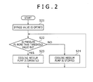
- Step S21 When the circulating pump is stopped, firstly, the bypass valve 12 is opened (Step S21).
- the heater 2 and the condenser 5 are communicated via the bypass path 11. If the heat medium flows into the heater 2, the working medium in liquid phase existing between the heater 2 and the circulating pump 7 is heated and evaporated, and the pressures of the upstream side path 81 and the downstream side path 82 rise.
- Step S22 whether the pressure P1 of the working medium detected by the upstream side sensor 9 is more than a threshold value th2 or not is determined (Step S22).
- the threshold value th2 is set lower than the upper limit th1 set to the upstream side safety valve 17 and the upper limit th3 set to the downstream side safety valve 18.
- the cooling medium pump 6 is driven by an instruction of the controller 14 (Step S23), and the cooling medium is supplied to the condenser 5.
- the working medium evaporated in the heater 2 is cooled forcibly and condensed in the condenser 5.
- the threshold value th2 is smaller than the above-mentioned upper limits th1 and th3, the upstream side safety valve 17 and the downstream side safety valve 18 are prevented from being opened.
- Step S22 After the elapse of a predetermined time, if the pressure P1 is detected again and the pressure P1 is less than the threshold value th2 (Step S22), driving of the cooling medium pump 6 is stopped (Step S24). Further, after the elapse of a predetermined time, the pressure P1 is detected again and compared to the threshold value th2 (Step S22). If the pressure P1 exceeds the threshold value th2 again, driving of the cooling medium pump 6 is restarted (Step S23), and the working medium is cooled in the condenser 5. In this way, when the thermal energy recovery device 1 is stopped, a rise of the pressures of the upstream side path 81 and the downstream side path 82 is prevented by repeatedly detecting the pressure P1. In addition, detection of the pressure P1 may be performed continuously. The same applies to the following other embodiments.
- a control for communicating the heater 2 and the condenser 5 after stopping the circulating pump 7 and a control (hereinafter, referred to as "a supply control”.) for supplying the cooling medium to the condenser 5 are performed.
- a communication control for communicating the heater 2 and the condenser 5 after stopping the circulating pump 7
- a supply control for supplying the cooling medium to the condenser 5 are performed.
- the working medium evaporated in the heater 2 is cooled forcibly and condensed, and an excessive rise of the pressures in the upstream side path 81 and the downstream side path 82, that is, the pressures on the upstream side and the downstream side of the expander 3 is prevented.
- operation (opening) of the upstream side safety valve 17 and the downstream side safety valve 18 are prevented.
- the communication control is performed in advance, and the supply control of the cooling medium is performed if the detection value of the upstream side sensor 9 exceeds the threshold value, so that unnecessary driving of the cooling medium pump 6 is prevented, and power consumption is reduced.
- the bypass path 11 the working medium evaporated in the heater 2 can be sent to the condenser 5 speedily.
- the whole volume of the working medium flows through the bypass valve 12 by closing the shut-off valve 13, thereby capable of sending the working medium to the condenser 5 more speedily. Since the supply control of the cooling medium is performed based on driving of the cooling medium pump 6, the flow volume of the cooling medium can be easily controlled.
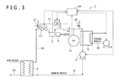
- Fig. 3 is a block diagram showing a configuration of a thermal energy recovery device according to another example of the first embodiment.
- the same reference numerals as those of the first embodiment will be given to the same components, and the detail description thereof will be omitted.
- a downstream side sensor 10 located in the downstream flow path 82 is provided in place of the upstream side sensor 9.
- the downstream side sensor 10 detects the pressure P2 of the working medium in gas phase in the downstream flow path 82.
- the downstream side sensor 10 sends a signal corresponding to the detection value, to the controller 14.
- Step S21 The operation of the controller 14 after stopping the circulating pump 7 is almost the same as Fig. 2 , and firstly, the bypass valve 12 is opened (Step S21). Whether the pressure P2 of the working medium detected by the downstream side sensor 10 is more than the threshold value th2 or not is determined (Step S22), and if it is determined that the pressure P2 is more than the threshold value th2 (the determination is YES), the cooling medium pump 6 is driven by an instruction of the controller 14 (Step S23). The working medium flowed out from the heater 2 is cooled forcibly and condensed in the condenser 5.
- Step S22 After the elapse of a predetermined time, if the pressure P2 is detected again and the pressure P2 is less than the threshold value th2 (Step S22), driving of the cooling medium pump 6 is stopped (Step S24). Further, after the elapse of a predetermined time, the pressure P2 is detected again and compared to the threshold value th2 (Step S22), and if the pressure P2 exceeds the threshold value th2, driving of the cooling medium pump 6 is restarted (Step S23), and the working medium is cooled in the condenser 5.
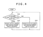
- Fig. 4 is a flow chart showing a pressure control operation of the controller 14.
- the configuration of the thermal energy recovery device 1 is similar to Fig. 1 .
- the pressure P1 of the working medium is detected by the upstream side sensor 9 located in the upstream flow path 81, in a state that the shut-off valve 13 and the bypass valve 12 are closed. Whether the pressure P1 is more than the threshold value th2 or not is determined (step S31). If the pressure P1 is less than the threshold value th2 (the determination is NO), the pressure P1 is detected again after the elapse of a predetermined time.
- the controller 14 performs a communication control for communicating the heater 2 and the condenser 5 by opening the bypass valve 12.
- the cooling medium pump 6 is driven in time with the communication control (Step S32), and a supply control for supplying the cooling medium to the condenser 5 is performed.
- the working medium evaporated in the heater 2 is cooled forcibly and condensed in the condenser 5.
- the communication control and the supply control do not always have to be simultaneously performed.
- Step S31 if the pressure P1 is detected again and the pressure P1 is less than the threshold value th2 (Step S31), the bypass valve 12 is closed and driving of the cooling medium pump 6 is stopped (Step S33). Further, after the elapse of a predetermined time, if the detected pressure P1 exceeds the threshold value th2 again (Step S31), the bypass valve 12 is opened and the cooling medium pump 6 is driven (Step S32), and the working medium is cooled in the condenser 5.
- the communication control and the supply control of the cooling medium are performed. Thereby, an excessive rise of the pressure in the upstream flow path 81 is prevented, and operation of the upstream side safety valve 17 is prevented. Since the supply control is performed if the detection value of the upstream side sensor 9 exceeds the threshold value, unnecessary driving of the cooling medium pump 6 is prevented.
- the cooling medium pump 6 does not always have to be driven if the detection value of the upstream side sensor 9 (or the downstream side sensor 10) exceeds the threshold value.
- the evaporated working medium may be condensed.
- the working medium evaporated in the heater 2 may be sent to the condenser 5 from both the bypass path 11 and a pathway from the upstream flow path 81 to the downstream flow path 82 via the expander 3. If a slight pressure difference is generated between the upstream and the downstream of the expander 3, a part of the working medium can flow into the condenser 5 via the expander 3.
- the shut-off valve 13 may be maintained in an opened state before and after stopping the circulating pump 7, in other words, the communication control may be performed before stopping the circulating pump 7. Also in the first embodiment, if the detection value of the upstream side sensor 9 exceeds the threshold value after stopping the circulating pump 7, the bypass valve 12 and the shut-off valve 13 are opened and the evaporated working medium may be sent to the condenser 5.
- the whole volume of the working medium may be sent to the condenser 5 via the expander 3 by closing the bypass valve 12 and opening the shut-off valve 13.
- a pressure sensor may be provided in the bypass path 11.
- the pressure sensor may be provided in an arbitrary position wherever in a pathway in the circulating flow path 8 from the heater 2 to the condenser 5.
- a temperature sensor may be provided in place of the pressure sensor. The communication control and the supply control are performed if the temperature of the working medium in gas phase detected by the temperature sensor exceeds a predetermined threshold value, thereby preventing an excessive rise of the pressure of the working medium in gas phase in the circulating flow path 8. The same applies to the second embodiment.
- the heater may consist of a plurality of heat exchangers.
- a thermal energy recovery device includes: a circulating flow path connected to a heater, an expander, a condenser and a circulating pump for circulating a working medium; a bypass valve in a bypass path connecting the upstream side region and the downstream side region of the expander in the circulating flow path; a power recovery machine connected to the expander; a circulating pump sending the working medium condensed in the condenser to the heater; a cooling medium pump sending a cooling medium to the condenser; an upstream side sensor detecting the pressure/temperature of the working medium on the expander upstream side in the circulating flow path; and a controller controlling the bypass valve and the cooling medium pump.
- the controller opens the bypass valve after stopping the circulating pump, and drives the cooling medium pump if the pressure/temperature of the working medium on the expander upstream side exceeds a threshold.
Landscapes
- Engineering & Computer Science (AREA)
- Chemical & Material Sciences (AREA)
- Combustion & Propulsion (AREA)
- Mechanical Engineering (AREA)
- General Engineering & Computer Science (AREA)
- Life Sciences & Earth Sciences (AREA)
- Sustainable Energy (AREA)
- Engine Equipment That Uses Special Cycles (AREA)
- Control Of Turbines (AREA)
Abstract
Description
- The present invention relates to a thermal energy recovery device for recovering exhaust heat.
- Conventionally, thermal energy recovery devices for recovering thermal energy such as geothermal water are known, and a representative thereof is a binary generator.
- Japanese Patent Application Laid-Open No.
H11-107906 - However, in the above prior art, a cooling water pump which supplies cooling water to the condenser remains stopped in a state that the power is turned off, so that forced cooling of the working medium by means of the cooling water is not performed. Therefore, even if the pressure regulating valve opens when the detection value of the pressure sensor exceeds the set value, an efficiency of reducing pressure in the closed loop is not sufficient, and operation of the safety valve cannot always be prevented.
- An object of the present invention is to provide a thermal energy recovery device capable of suppressing an excessive rise of pressure in a circulating flow path of the working medium after stopping a circulating pump.
- As a means for solving the above problem, the present invention is a thermal energy recovery device including: a heater which heats a working medium by exchanging heat between a heat medium and the working medium; an expander into which the working medium flowed out from the heater flows; a power recovery machine connected to the expander; a condenser which condenses the working medium flowed into from the expander by heat exchange with a cooling medium; a circulating pump which sends the working medium condensed in the condenser to the heater; a circulating flow path which connects the heater, the expander, the condenser and the circulating pump and through which the working medium circulates; a bypass path which connects the region on the upstream side than the expander, in the circulating flow path, and the region on the downstream side than the expander; a bypass valve provided in the bypass path; a cooling medium pump which sends the cooling medium to the condenser; and a controller, in which the controller executes a communication control that is a control for communicating the heater and the condenser via the bypass path by opening the bypass valve, in order to condense the working medium evaporated in the heater, when the stoppage of the circulating pump is detected.
- In the thermal energy recovery device, after stopping the circulating pump, the working medium evaporated in the heater can be sent speedily to the condenser, so that an excessive rise of pressure in the circulating flow path by the working medium heated in the heater is prevented.
- In the present invention, the thermal energy recovery device includes the cooling medium pump which sends the cooling medium to the condenser, and the controller preferably executes a supply control that is a control for supplying the cooling medium to the condenser by driving the cooling medium pump, in order to condense the working medium evaporated in the heater, when the stoppage of the circulating pump is detected.
- In such a manner, the flow volume of the cooling medium can be easily controlled.
- Moreover, in the present invention, preferably, the thermal energy recovery device further includes a sensor which is arranged in a pathway in the circulating flow path from the heater to the condenser and detects the pressure or temperature of the working medium, and the controller executes only the communication control ahead, and executes the supply control if a detection value of the sensor exceeds a threshold value.
- In such a manner, the cooling medium is prevented from being sent unnecessarily.
- Moreover, in the present invention, preferably, the thermal energy recovery device further includes a sensor which is arranged in a region between the heater and the expander in the circulating flow path and detects the pressure or temperature of the working medium, and the controller executes the communication control and the supply control if a detection value of the sensor exceeds a threshold value.
- In such a manner, the cooling medium is prevented from being sent unnecessarily.
- Moreover, in the present invention, preferably, the thermal energy recovery device further includes a shut-off valve which shuts off the working medium flowing into the expander, and the controller closes the shut-off valve in time with the stoppage of the circulating pump.
- In such a manner, the whole volume of the evaporated working medium can be sent to the condenser via the bypass path, and the pressure can be reduced more speedily.
- Moreover, the present invention is a pressure control method at the time of stoppage of a thermal energy recovery device provided with a circulating flow path which circulates a working medium between a heater, an expander, a condenser and a circulating pump, and a power recovery machine connected to the expander, including a stopping step of stopping the circulating pump, a communicating step of communicating the heater and the condenser after the stopping step, and a supplying step which is a control for supplying a cooling medium to the condenser after the stopping step.
- In the control method, after stopping the circulating pump, an excessive rise of pressure in the circulating flow path by the working medium heated in the heater is prevented.
- As described above, according to the present invention, the thermal energy recovery device capable of suppressing an excessive rise of pressure of the working medium in the circulating flow path after stopping the circulating pump can be provided.
-
-
Fig. 1 is a block diagram showing a configuration of a thermal energy recovery device according to a first embodiment of the present invention. -
Fig. 2 is a flow chart showing an operation of a controller of the thermal energy recovery device. -
Fig. 3 is a block diagram showing a configuration of a thermal energy recovery device according to a second embodiment of the present invention. -
Fig. 4 is a flow chart showing an operation of a controller of the thermal energy recovery device. - Hereinafter, preferred embodiments of the present invention will be described in detail with reference to the accompanying drawings.
-
Fig. 1 is a block diagram showing a configuration of a thermal energy recovery device 1 according to a first embodiment of the present invention. InFig. 1 , solid arrows show flows of various media, and dashed arrows show flows of electric signals. The thermal energy recovery device 1 includes aheater 2, anexpander 3, acondenser 5, a circulatingpump 7, a generator 4 which is a power recovery machine, acooling medium pump 6, a circulatingflow path 8, and acontroller 14. The thermal energy recovery device 1 further includes a shut-offvalve 13, anupstream side sensor 9, an upstreamside safety valve 17, and a downstreamside safety valve 18. The generator 4 is connected to theexpander 3. Theheater 2, theexpander 3, thecondenser 5 and the circulatingpump 7 are connected to the circulatingflow path 8 in this order, and a working medium circulates between these members. For example, as the working medium, low boiling point organic media (Freon or the like) such as R245fa whose boiling point is lower than that of water can be used. In the following description, of the circulatingflow path 8, the region between theheater 2 and theexpander 3, which is the region on the upstream side of theexpander 3, is referred to as "anupstream path 81". Of the circulatingflow path 8, the region between theexpander 3 and thecondenser 5, which is the region on the downstream side of theexpander 3, is referred to as "adownstream path 82". The circulatingflow path 8 includes abypass path 11 which bypasses theexpander 3, and abypass valve 12 provided on thebypass path 11. Thecontroller 14 performs an open/close control of the shut-offvalve 13 and thebypass valve 12 and a drive control of the circulatingpump 7 and thecooling medium pump 6. - The
heater 2 has a flow path through which the working medium flows and a flow path through which a heat medium flows, exchanges heat between the working medium and the heat medium, and heats and evaporates the working medium in liquid phase. In the gravity direction, theheater 2 is located below thecondenser 5. For example, exhaust heat from an internal combustion engine, of ships or the like, or compressed air discharged from a supercharger, and the like are used as the heat medium. Moreover, the heat medium may include high temperature compressed gas discharged from a compressor, and the like, but it is not limited specifically. In the thermal energy recovery device 1, the heat medium flows into theheater 2 constantly or intermittently regardless of whether it is being driven or stopped. - The
expander 3 is a screw expander and is arranged on the downstream side of theheater 2 in the circulatingflow path 8. The working medium in gas phase flowed out from theheater 2 flows into theexpander 3. As the expander, a scroll-type or a turbo-type may be used. In theexpander 3, a rotor within theexpander 3 rotates by expanding the working medium. Thereby, the generator 4 connected to theexpander 3 generates power. - The
condenser 5 has a flow path through which a cooling medium flows and a flow path through which the working medium flows, exchanges heat between the cooling medium and the working medium flowed into from theexpander 3, and cools and condenses the working medium. In addition, a reservoir for storing the working medium in liquid phase may be provided between thecondenser 5 and the circulatingpump 7 in the circulatingflow path 8. The cooling medium is sent to thecondenser 5 by thecooling medium pump 6 provided in a coolingmedium flow path 16, and deprives heat from the working medium in thecondenser 5. For example, thecooling medium pump 6 is a centrifugal pump including an impeller as a rotor, a gear pump having a rotor consisting of a pair of gears, or the like. - The circulating
pump 7 is provided between thecondenser 5 and theheater 2 in the circulatingflow path 8, and sends the working medium condensed in thecondenser 5 to theheater 2. For example, a centrifugal pump or a gear pump is used as the circulatingpump 7. The circulatingpump 7 sends the information about whether it is operated or stopped, to thecontroller 14. Here, the stoppage of the circulatingpump 7 includes not only the stoppage of a pressurizing part of the circulatingpump 7 but also the state that a stop control is performed to a driving part for driving the pressurizing part and the pressurizing part does not substantially pressurize the working medium. - Both ends of the
bypass path 11 are connected to theupstream side path 81 which is the region on the upstream side of theexpander 3 and thedownstream side path 82 which is the region on the downstream side thereof. By providing thebypass path 11, the working medium flowed out from theheater 2 can bypass theexpander 3 and flow into thecondenser 5. Thebypass valve 12 is provided in thebypass path 11. Thebypass valve 12 may be an opening and closing valve only capable of opening and closing, or may be a flow control valve capable of adjusting opening. - The shut-off
valve 13 is located on theexpander 3 side than the position to which the end of thebypass path 11 is connected, of theupstream side path 81. By closing the shut-offvalve 13, the working medium flowing into theexpander 3 from theheater 2 is shut off. The shut-offvalve 13 can control opening and closing thereof by thecontroller 14 described later. - The
upstream side sensor 9 is a pressure sensor, and is located between theheater 2 and the shut-offvalve 13 and detects a pressure P1 of the working medium in theupstream side path 81. Theupstream side sensor 9 sends a signal corresponding to a detection value, to thecontroller 14. - The upstream
side safety valve 17 is located between theheater 2 and the shut-offvalve 13. The upstreamside safety valve 17 is opened when the pressure P1 of the working medium in theupstream side path 81 exceeds an upper limit th1. The upper limit th1 is a design pressure (or an allowable pressure) of theupstream side path 81. By opening the upstreamside safety valve 17, the working medium is escaped to the outside, thereby preventing an abnormal increase in the pressure of theupstream side path 81. - The downstream
side safety valve 18 is located in thedownstream side path 82, and is opened when a pressure P2 of the working medium in gas phase in thedownstream side path 82 exceeds an upper limit th3. By opening the downstreamside safety valve 18, the working medium is escaped to the outside, thereby preventing an excessive rise of the pressure of thedownstream side path 82. The upper limit th3 is a design pressure (or an allowable pressure) of thedownstream side path 82, and is set to a value lower than the upper limit th1. - Next, a pressure control operation of the
controller 14 after stopping the thermal energy recovery device 1, that is, after stopping the circulatingpump 7, will be described with reference toFig. 2 . When the thermal energy recovery device 1 is stopped, the circulatingpump 7 is stopped. Further, the shut-offvalve 13 is closed in time with the stoppage of the circulatingpump 7, and theexpander 3 is stopped. Between theheater 2 and the circulatingpump 7, the working medium in liquid phase which is not evaporated in theheater 2 remains. Moreover, as mentioned previously, since theheater 2 is located below thecondenser 5 in the gravity direction, the working medium in liquid phase may leak between theheater 2 and the circulatingpump 7 through gaps between members of the circulatingpump 7 from the condenser 5 (or the reservoir (not shown)). - When the circulating pump is stopped, firstly, the
bypass valve 12 is opened (Step S21). Theheater 2 and thecondenser 5 are communicated via thebypass path 11. If the heat medium flows into theheater 2, the working medium in liquid phase existing between theheater 2 and the circulatingpump 7 is heated and evaporated, and the pressures of theupstream side path 81 and thedownstream side path 82 rise. In thecontroller 14, whether the pressure P1 of the working medium detected by theupstream side sensor 9 is more than a threshold value th2 or not is determined (Step S22). The threshold value th2 is set lower than the upper limit th1 set to the upstreamside safety valve 17 and the upper limit th3 set to the downstreamside safety valve 18. If it is determined that the pressure P1 is more than the threshold value th2 (the determination is YES), the coolingmedium pump 6 is driven by an instruction of the controller 14 (Step S23), and the cooling medium is supplied to thecondenser 5. The working medium evaporated in theheater 2 is cooled forcibly and condensed in thecondenser 5. As a result, a rise of the pressure of the working medium in theupstream side path 81 and thedownstream side path 82 is prevented. Since the threshold value th2 is smaller than the above-mentioned upper limits th1 and th3, the upstreamside safety valve 17 and the downstreamside safety valve 18 are prevented from being opened. - After the elapse of a predetermined time, if the pressure P1 is detected again and the pressure P1 is less than the threshold value th2 (Step S22), driving of the cooling
medium pump 6 is stopped (Step S24). Further, after the elapse of a predetermined time, the pressure P1 is detected again and compared to the threshold value th2 (Step S22). If the pressure P1 exceeds the threshold value th2 again, driving of the coolingmedium pump 6 is restarted (Step S23), and the working medium is cooled in thecondenser 5. In this way, when the thermal energy recovery device 1 is stopped, a rise of the pressures of theupstream side path 81 and thedownstream side path 82 is prevented by repeatedly detecting the pressure P1. In addition, detection of the pressure P1 may be performed continuously. The same applies to the following other embodiments. - As described above, in the thermal energy recovery device 1 according to the present embodiment, a control (hereinafter, referred to as "a communication control".) for communicating the
heater 2 and thecondenser 5 after stopping the circulatingpump 7 and a control (hereinafter, referred to as "a supply control".) for supplying the cooling medium to thecondenser 5 are performed. Thereby, the working medium evaporated in theheater 2 is cooled forcibly and condensed, and an excessive rise of the pressures in theupstream side path 81 and thedownstream side path 82, that is, the pressures on the upstream side and the downstream side of theexpander 3 is prevented. As a result, operation (opening) of the upstreamside safety valve 17 and the downstreamside safety valve 18 are prevented. - In the thermal energy recovery device 1, after stopping the circulating
pump 7, the communication control is performed in advance, and the supply control of the cooling medium is performed if the detection value of theupstream side sensor 9 exceeds the threshold value, so that unnecessary driving of the coolingmedium pump 6 is prevented, and power consumption is reduced. By providing thebypass path 11, the working medium evaporated in theheater 2 can be sent to thecondenser 5 speedily. The whole volume of the working medium flows through thebypass valve 12 by closing the shut-offvalve 13, thereby capable of sending the working medium to thecondenser 5 more speedily. Since the supply control of the cooling medium is performed based on driving of the coolingmedium pump 6, the flow volume of the cooling medium can be easily controlled. -
Fig. 3 is a block diagram showing a configuration of a thermal energy recovery device according to another example of the first embodiment. In addition, the same reference numerals as those of the first embodiment will be given to the same components, and the detail description thereof will be omitted. In the circulatingflow path 8 of the thermal energy recovery device 1, adownstream side sensor 10 located in thedownstream flow path 82 is provided in place of theupstream side sensor 9. Thedownstream side sensor 10 detects the pressure P2 of the working medium in gas phase in thedownstream flow path 82. Thedownstream side sensor 10 sends a signal corresponding to the detection value, to thecontroller 14. - The operation of the
controller 14 after stopping the circulatingpump 7 is almost the same asFig. 2 , and firstly, thebypass valve 12 is opened (Step S21). Whether the pressure P2 of the working medium detected by thedownstream side sensor 10 is more than the threshold value th2 or not is determined (Step S22), and if it is determined that the pressure P2 is more than the threshold value th2 (the determination is YES), the coolingmedium pump 6 is driven by an instruction of the controller 14 (Step S23). The working medium flowed out from theheater 2 is cooled forcibly and condensed in thecondenser 5. After the elapse of a predetermined time, if the pressure P2 is detected again and the pressure P2 is less than the threshold value th2 (Step S22), driving of the coolingmedium pump 6 is stopped (Step S24). Further, after the elapse of a predetermined time, the pressure P2 is detected again and compared to the threshold value th2 (Step S22), and if the pressure P2 exceeds the threshold value th2, driving of the coolingmedium pump 6 is restarted (Step S23), and the working medium is cooled in thecondenser 5. - In the thermal energy recovery device 1, an excessive rise of the pressures in the
upstream side path 81 and thedownstream side path 82 is prevented, and opening of the upstreamside safety valve 17 and the downstreamside safety valve 18 is prevented. - Next, another operation example of the
controller 14 at the time of stoppage of the thermal energy recovery device 1 will be described as a second embodiment.Fig. 4 is a flow chart showing a pressure control operation of thecontroller 14. The configuration of the thermal energy recovery device 1 is similar toFig. 1 . When the circulatingpump 7 is stopped, the pressure P1 of the working medium is detected by theupstream side sensor 9 located in theupstream flow path 81, in a state that the shut-offvalve 13 and thebypass valve 12 are closed. Whether the pressure P1 is more than the threshold value th2 or not is determined (step S31). If the pressure P1 is less than the threshold value th2 (the determination is NO), the pressure P1 is detected again after the elapse of a predetermined time. If it is determined that the pressure P1 is more than the threshold value th2 (the determination is YES), thecontroller 14 performs a communication control for communicating theheater 2 and thecondenser 5 by opening thebypass valve 12. The coolingmedium pump 6 is driven in time with the communication control (Step S32), and a supply control for supplying the cooling medium to thecondenser 5 is performed. Thereby, the working medium evaporated in theheater 2 is cooled forcibly and condensed in thecondenser 5. In addition, as long as the working medium can be condensed in thecondenser 5, the communication control and the supply control do not always have to be simultaneously performed. - Then, after the elapse of a predetermined time, if the pressure P1 is detected again and the pressure P1 is less than the threshold value th2 (Step S31), the
bypass valve 12 is closed and driving of the coolingmedium pump 6 is stopped (Step S33). Further, after the elapse of a predetermined time, if the detected pressure P1 exceeds the threshold value th2 again (Step S31), thebypass valve 12 is opened and the coolingmedium pump 6 is driven (Step S32), and the working medium is cooled in thecondenser 5. - In the second embodiment, after stopping the circulating
pump 7, if the pressure of the working medium in theupstream flow path 81 exceeds the threshold value, the communication control and the supply control of the cooling medium are performed. Thereby, an excessive rise of the pressure in theupstream flow path 81 is prevented, and operation of the upstreamside safety valve 17 is prevented. Since the supply control is performed if the detection value of theupstream side sensor 9 exceeds the threshold value, unnecessary driving of the coolingmedium pump 6 is prevented. - Hereinbefore, although the embodiments of the present invention are described, the present invention is not limited to the above embodiments, and various modifications are possible.
- In the first embodiment, the cooling
medium pump 6 does not always have to be driven if the detection value of the upstream side sensor 9 (or the downstream side sensor 10) exceeds the threshold value. By continuing driving of the coolingmedium pump 6 even after stopping the circulatingpump 7, in other words, by performing the supply control of the cooling medium before stopping the circulatingpump 7, the evaporated working medium may be condensed. The same applies to the second embodiment. - In the second embodiment, after stopping the circulating
pump 7, by opening thebypass valve 12 and the shut-offvalve 13, the working medium evaporated in theheater 2 may be sent to thecondenser 5 from both thebypass path 11 and a pathway from theupstream flow path 81 to thedownstream flow path 82 via theexpander 3. If a slight pressure difference is generated between the upstream and the downstream of theexpander 3, a part of the working medium can flow into thecondenser 5 via theexpander 3. In addition, the shut-offvalve 13 may be maintained in an opened state before and after stopping the circulatingpump 7, in other words, the communication control may be performed before stopping the circulatingpump 7. Also in the first embodiment, if the detection value of theupstream side sensor 9 exceeds the threshold value after stopping the circulatingpump 7, thebypass valve 12 and the shut-offvalve 13 are opened and the evaporated working medium may be sent to thecondenser 5. - In the above embodiments, as the communication control of the
controller 14, the whole volume of the working medium may be sent to thecondenser 5 via theexpander 3 by closing thebypass valve 12 and opening the shut-offvalve 13. - In the above first embodiment, a pressure sensor may be provided in the
bypass path 11. In this way, the pressure sensor may be provided in an arbitrary position wherever in a pathway in the circulatingflow path 8 from theheater 2 to thecondenser 5. Moreover, a correspondence relation exists between the temperature and the pressure of the working medium in gas phase, and therefore a temperature sensor may be provided in place of the pressure sensor. The communication control and the supply control are performed if the temperature of the working medium in gas phase detected by the temperature sensor exceeds a predetermined threshold value, thereby preventing an excessive rise of the pressure of the working medium in gas phase in the circulatingflow path 8. The same applies to the second embodiment. - In the thermal energy recovery device 1, the heater may consist of a plurality of heat exchangers.
- A thermal energy recovery device includes: a circulating flow path connected to a heater, an expander, a condenser and a circulating pump for circulating a working medium; a bypass valve in a bypass path connecting the upstream side region and the downstream side region of the expander in the circulating flow path; a power recovery machine connected to the expander; a circulating pump sending the working medium condensed in the condenser to the heater; a cooling medium pump sending a cooling medium to the condenser; an upstream side sensor detecting the pressure/temperature of the working medium on the expander upstream side in the circulating flow path; and a controller controlling the bypass valve and the cooling medium pump. The controller opens the bypass valve after stopping the circulating pump, and drives the cooling medium pump if the pressure/temperature of the working medium on the expander upstream side exceeds a threshold.
Claims (7)
- A thermal energy recovery device comprising:a heater which heats a working medium by exchanging heat between a heat medium and the working medium;an expander into which the working medium flowed out from the heater flows;a power recovery machine connected to the expander;a condenser which condenses the working medium flowed into from the expander by heat exchange with a cooling medium;a circulating pump which sends the working medium condensed in the condenser to the heater;a circulating flow path which connects the heater, the expander, the condenser and the circulating pump and through which the working medium circulates;a bypass path which connects the region on the upstream side than the expander, in the circulating flow path, and the region on the downstream side than the expander;a bypass valve provided in the bypass path;a cooling medium pump which sends the cooling medium to the condenser; anda controller,wherein the controller executes a communication control that is a control for communicating the heater and the condenser via the bypass path by opening the bypass valve, in order to condense the working medium evaporated in the heater, when the stoppage of the circulating pump is detected.
- The thermal energy recovery device according to claim 1, comprising:the cooling medium pump which sends the cooling medium to the condenser,wherein the controller executes a supply control that is a control for supplying the cooling medium to the condenser by driving the cooling medium pump, in order to condense the working medium evaporated in the heater, when the stoppage of the circulating pump is detected.
- The thermal energy recovery device according to claim 2, further comprising:a sensor which is arranged in a pathway in the circulating flow path from the heater to the condenser and detects the pressure or temperature of the working medium,wherein the controller executes the communication control ahead, and executes the supply control if a detection value of the sensor exceeds a threshold value.
- The thermal energy recovery device according to claim 2, further comprising:a sensor which is arranged in a region between the heater and the expander in the circulating flow path and detects the pressure or temperature of the working medium,wherein the controller executes the communication control and the supply control if a detection value of the sensor exceeds a threshold value.
- The thermal energy recovery device according to claim 1, further comprising:a shut-off valve which shuts off the working medium flowing into the expander,wherein the controller closes the shut-off valve in time with the stoppage of the circulating pump.
- A pressure control method at the time of stoppage of a thermal energy recovery device provided with a circulating flow path which circulates a working medium between a heater, an expander, a condenser and a circulating pump, and a power recovery machine connected to the expander, comprising:a stopping step of stopping the circulating pump,a communicating step of communicating the heater and the condenser after the stopping step, anda supplying step which is a control for supplying a cooling medium to the condenser after the stopping step.
- The control method of the thermal energy recovery device according to claim 6, further comprising:a detecting step of detecting the pressure or temperature of the working medium on the upstream side of the expander in the circulating flow path after the stopping step; anda cooling step of sending the cooling medium to the condenser by operating the cooling medium pump if the pressure or temperature detected in the detecting step exceeds a threshold value.
Applications Claiming Priority (1)
| Application Number | Priority Date | Filing Date | Title |
|---|---|---|---|
| JP2014101580A JP6198673B2 (en) | 2014-05-15 | 2014-05-15 | Thermal energy recovery device and control method |
Publications (2)
| Publication Number | Publication Date |
|---|---|
| EP2944812A1 true EP2944812A1 (en) | 2015-11-18 |
| EP2944812B1 EP2944812B1 (en) | 2016-08-31 |
Family
ID=52810946
Family Applications (1)
| Application Number | Title | Priority Date | Filing Date |
|---|---|---|---|
| EP15159190.6A Not-in-force EP2944812B1 (en) | 2014-05-15 | 2015-03-16 | Thermal energy recovery device and control method |
Country Status (6)
| Country | Link |
|---|---|
| US (1) | US9797272B2 (en) |
| EP (1) | EP2944812B1 (en) |
| JP (1) | JP6198673B2 (en) |
| KR (2) | KR102015689B1 (en) |
| CN (1) | CN105089721B (en) |
| DK (1) | DK2944812T3 (en) |
Cited By (2)
| Publication number | Priority date | Publication date | Assignee | Title |
|---|---|---|---|---|
| EP3418654A1 (en) * | 2017-06-21 | 2018-12-26 | Kabushiki Kaisha Kobe Seiko Sho (Kobe Steel, Ltd.) | Impurity recovery method and oil recovery method |
| EP3492713A3 (en) * | 2017-11-22 | 2019-08-14 | Kabushiki Kaisha Kobe Seiko Sho (Kobe Steel, Ltd.) | Thermal energy recovery system |
Families Citing this family (12)
| Publication number | Priority date | Publication date | Assignee | Title |
|---|---|---|---|---|
| JP6670122B2 (en) * | 2016-02-19 | 2020-03-18 | 株式会社神戸製鋼所 | Geothermal recovery device and operation method of geothermal recovery device |
| JP6595395B2 (en) * | 2016-04-14 | 2019-10-23 | 株式会社神戸製鋼所 | Thermal energy recovery device and operation method thereof |
| JP6616235B2 (en) * | 2016-05-10 | 2019-12-04 | 株式会社神戸製鋼所 | Waste heat recovery system |
| JP2018053862A (en) * | 2016-09-30 | 2018-04-05 | 株式会社神戸製鋼所 | Thermal energy recovery system |
| JP6751031B2 (en) * | 2017-02-06 | 2020-09-02 | 株式会社神戸製鋼所 | Thermal energy recovery device |
| JP6769888B2 (en) * | 2017-02-09 | 2020-10-14 | 株式会社神戸製鋼所 | Thermal energy recovery device |
| KR20190016734A (en) * | 2017-08-09 | 2019-02-19 | 두산중공업 주식회사 | Power generation plant and control method thereof |
| JP2020186691A (en) * | 2019-05-15 | 2020-11-19 | 株式会社神戸製鋼所 | Heat recovery device and method for collecting working medium of heat recovery device |
| JP7236990B2 (en) * | 2019-12-09 | 2023-03-10 | 株式会社荏原製作所 | System and polishing equipment for adjusting the surface temperature of the pad |
| CN112459983B (en) * | 2020-11-24 | 2022-03-01 | 清华四川能源互联网研究院 | A comprehensive energy supply system and method with compressed air energy storage |
| US11649759B2 (en) * | 2021-10-12 | 2023-05-16 | Transportation Ip Holdings, Llc | System and method for thermal management |
| US12117321B2 (en) * | 2022-05-04 | 2024-10-15 | Intellihot, Inc. | Diagnostic methods |
Citations (4)
| Publication number | Priority date | Publication date | Assignee | Title |
|---|---|---|---|---|
| JPH11107906A (en) | 1997-09-30 | 1999-04-20 | Hisaka Works Ltd | Binary power generation system |
| US20120261112A1 (en) * | 2011-04-18 | 2012-10-18 | Agosto Corporation Ltd. | System for reducing oil beneath the ground |
| EP2578817A2 (en) * | 2011-10-03 | 2013-04-10 | Kabushiki Kaisha Kobe Seiko Sho (Kobe Steel, Ltd.) | Power generation apparatus |
| EP2647841A1 (en) * | 2012-04-02 | 2013-10-09 | Alstom Technology Ltd | Solar thermal power system |
Family Cites Families (10)
| Publication number | Priority date | Publication date | Assignee | Title |
|---|---|---|---|---|
| JPS5922043B2 (en) | 1979-08-24 | 1984-05-24 | 株式会社日立製作所 | Cold energy power generation plant |
| JPS5724405A (en) | 1980-07-22 | 1982-02-09 | Chiyoda Chem Eng & Constr Co Ltd | Method of controlling exhaust pressure of turbine of rankine cycle at stopping and starting of said turbine |
| JPS59129304A (en) * | 1983-01-13 | 1984-07-25 | 株式会社東芝 | Binary cycle plant |
| US6986251B2 (en) * | 2003-06-17 | 2006-01-17 | Utc Power, Llc | Organic rankine cycle system for use with a reciprocating engine |
| JP4684761B2 (en) * | 2005-06-27 | 2011-05-18 | 株式会社荏原製作所 | Power generator |
| JP2008008217A (en) * | 2006-06-29 | 2008-01-17 | Ebara Corp | Power generator |
| JP4823998B2 (en) * | 2007-11-09 | 2011-11-24 | 新日鉄エンジニアリング株式会社 | Waste power generation method |
| US8220266B2 (en) * | 2009-03-12 | 2012-07-17 | General Electric Company | Condenser for power plant |
| JP5597597B2 (en) | 2011-06-09 | 2014-10-01 | 株式会社神戸製鋼所 | Power generator |
| JP5871663B2 (en) * | 2012-03-01 | 2016-03-01 | 株式会社神戸製鋼所 | Control method of binary power generator |
-
2014
- 2014-05-15 JP JP2014101580A patent/JP6198673B2/en not_active Expired - Fee Related
-
2015
- 2015-03-16 DK DK15159190.6T patent/DK2944812T3/en active
- 2015-03-16 EP EP15159190.6A patent/EP2944812B1/en not_active Not-in-force
- 2015-03-30 US US14/672,768 patent/US9797272B2/en not_active Expired - Fee Related
- 2015-05-12 KR KR1020150065758A patent/KR102015689B1/en not_active Expired - Fee Related
- 2015-05-15 CN CN201510247457.7A patent/CN105089721B/en not_active Expired - Fee Related
-
2017
- 2017-10-30 KR KR1020170142341A patent/KR20170124991A/en not_active Withdrawn
Patent Citations (4)
| Publication number | Priority date | Publication date | Assignee | Title |
|---|---|---|---|---|
| JPH11107906A (en) | 1997-09-30 | 1999-04-20 | Hisaka Works Ltd | Binary power generation system |
| US20120261112A1 (en) * | 2011-04-18 | 2012-10-18 | Agosto Corporation Ltd. | System for reducing oil beneath the ground |
| EP2578817A2 (en) * | 2011-10-03 | 2013-04-10 | Kabushiki Kaisha Kobe Seiko Sho (Kobe Steel, Ltd.) | Power generation apparatus |
| EP2647841A1 (en) * | 2012-04-02 | 2013-10-09 | Alstom Technology Ltd | Solar thermal power system |
Cited By (3)
| Publication number | Priority date | Publication date | Assignee | Title |
|---|---|---|---|---|
| EP3418654A1 (en) * | 2017-06-21 | 2018-12-26 | Kabushiki Kaisha Kobe Seiko Sho (Kobe Steel, Ltd.) | Impurity recovery method and oil recovery method |
| KR20180138526A (en) * | 2017-06-21 | 2018-12-31 | 가부시키가이샤 고베 세이코쇼 | Impurity recovery method and oil recovery method |
| EP3492713A3 (en) * | 2017-11-22 | 2019-08-14 | Kabushiki Kaisha Kobe Seiko Sho (Kobe Steel, Ltd.) | Thermal energy recovery system |
Also Published As
| Publication number | Publication date |
|---|---|
| US20150330256A1 (en) | 2015-11-19 |
| EP2944812B1 (en) | 2016-08-31 |
| KR20170124991A (en) | 2017-11-13 |
| US9797272B2 (en) | 2017-10-24 |
| KR102015689B1 (en) | 2019-08-28 |
| DK2944812T3 (en) | 2016-12-05 |
| KR20150131983A (en) | 2015-11-25 |
| CN105089721A (en) | 2015-11-25 |
| JP2015218626A (en) | 2015-12-07 |
| CN105089721B (en) | 2018-03-20 |
| JP6198673B2 (en) | 2017-09-20 |
Similar Documents
| Publication | Publication Date | Title |
|---|---|---|
| EP2944812B1 (en) | Thermal energy recovery device and control method | |
| KR101708108B1 (en) | Waste heat recovery system and waste heat recovery method | |
| CN102099560B (en) | Exhaust heat regeneration system | |
| KR101600687B1 (en) | Heat recovery apparatus and operation control method of heat recovery apparatus | |
| US20130014505A1 (en) | Waste heat regeneration system | |
| JP2017145812A (en) | Exhaust heat recovery system and binary device | |
| JP2010174848A (en) | Waste heat regeneration system | |
| US20150322821A1 (en) | Thermal energy recovery device and start-up method of thermal energy recovery device | |
| CN105042952A (en) | Device for controlling a closed circuit operating with a rankine cycle and method for using same | |
| CN106460546B (en) | Power generator | |
| JP2013113192A (en) | Waste heat regeneration system | |
| US10883378B2 (en) | Combined cycle plant and method for controlling operation of combine cycle plant | |
| US20140318131A1 (en) | Heat sources for thermal cycles | |
| JP6981727B2 (en) | Industrial equipment | |
| CN107110066B (en) | Waste heat recovery device | |
| JP4294508B2 (en) | Cooling device operation method | |
| JP5653320B2 (en) | Waste heat regeneration system | |
| CN108412561B (en) | Heat energy recovery device | |
| CN112105801A (en) | Rankine cycle apparatus and control method thereof | |
| JP6854262B2 (en) | Exhaust heat recovery system | |
| US10851678B2 (en) | Thermal energy recovery device and startup operation method for the same | |
| JP2016508567A (en) | Apparatus and method for operation control and safety control of a heat engine |
Legal Events
| Date | Code | Title | Description |
|---|---|---|---|
| PUAI | Public reference made under article 153(3) epc to a published international application that has entered the european phase |
Free format text: ORIGINAL CODE: 0009012 |
|
| 17P | Request for examination filed |
Effective date: 20150316 |
|
| AK | Designated contracting states |
Kind code of ref document: A1 Designated state(s): AL AT BE BG CH CY CZ DE DK EE ES FI FR GB GR HR HU IE IS IT LI LT LU LV MC MK MT NL NO PL PT RO RS SE SI SK SM TR |
|
| AX | Request for extension of the european patent |
Extension state: BA ME |
|
| GRAP | Despatch of communication of intention to grant a patent |
Free format text: ORIGINAL CODE: EPIDOSNIGR1 |
|
| INTG | Intention to grant announced |
Effective date: 20160307 |
|
| GRAS | Grant fee paid |
Free format text: ORIGINAL CODE: EPIDOSNIGR3 |
|
| GRAA | (expected) grant |
Free format text: ORIGINAL CODE: 0009210 |
|
| AK | Designated contracting states |
Kind code of ref document: B1 Designated state(s): AL AT BE BG CH CY CZ DE DK EE ES FI FR GB GR HR HU IE IS IT LI LT LU LV MC MK MT NL NO PL PT RO RS SE SI SK SM TR |
|
| REG | Reference to a national code |
Ref country code: CH Ref legal event code: EP Ref country code: GB Ref legal event code: FG4D |
|
| REG | Reference to a national code |
Ref country code: IE Ref legal event code: FG4D |
|
| REG | Reference to a national code |
Ref country code: AT Ref legal event code: REF Ref document number: 825239 Country of ref document: AT Kind code of ref document: T Effective date: 20161015 |
|
| REG | Reference to a national code |
Ref country code: DE Ref legal event code: R096 Ref document number: 602015000255 Country of ref document: DE |
|
| REG | Reference to a national code |
Ref country code: DK Ref legal event code: T3 Effective date: 20161128 |
|
| REG | Reference to a national code |
Ref country code: LT Ref legal event code: MG4D |
|
| REG | Reference to a national code |
Ref country code: NL Ref legal event code: MP Effective date: 20160831 |
|
| REG | Reference to a national code |
Ref country code: NO Ref legal event code: T2 Effective date: 20160831 |
|
| REG | Reference to a national code |
Ref country code: AT Ref legal event code: MK05 Ref document number: 825239 Country of ref document: AT Kind code of ref document: T Effective date: 20160831 |
|
| PG25 | Lapsed in a contracting state [announced via postgrant information from national office to epo] |
Ref country code: RS Free format text: LAPSE BECAUSE OF FAILURE TO SUBMIT A TRANSLATION OF THE DESCRIPTION OR TO PAY THE FEE WITHIN THE PRESCRIBED TIME-LIMIT Effective date: 20160831 Ref country code: FI Free format text: LAPSE BECAUSE OF FAILURE TO SUBMIT A TRANSLATION OF THE DESCRIPTION OR TO PAY THE FEE WITHIN THE PRESCRIBED TIME-LIMIT Effective date: 20160831 Ref country code: HR Free format text: LAPSE BECAUSE OF FAILURE TO SUBMIT A TRANSLATION OF THE DESCRIPTION OR TO PAY THE FEE WITHIN THE PRESCRIBED TIME-LIMIT Effective date: 20160831 Ref country code: LT Free format text: LAPSE BECAUSE OF FAILURE TO SUBMIT A TRANSLATION OF THE DESCRIPTION OR TO PAY THE FEE WITHIN THE PRESCRIBED TIME-LIMIT Effective date: 20160831 |
|
| PG25 | Lapsed in a contracting state [announced via postgrant information from national office to epo] |
Ref country code: ES Free format text: LAPSE BECAUSE OF FAILURE TO SUBMIT A TRANSLATION OF THE DESCRIPTION OR TO PAY THE FEE WITHIN THE PRESCRIBED TIME-LIMIT Effective date: 20160831 Ref country code: NL Free format text: LAPSE BECAUSE OF FAILURE TO SUBMIT A TRANSLATION OF THE DESCRIPTION OR TO PAY THE FEE WITHIN THE PRESCRIBED TIME-LIMIT Effective date: 20160831 Ref country code: LV Free format text: LAPSE BECAUSE OF FAILURE TO SUBMIT A TRANSLATION OF THE DESCRIPTION OR TO PAY THE FEE WITHIN THE PRESCRIBED TIME-LIMIT Effective date: 20160831 Ref country code: AT Free format text: LAPSE BECAUSE OF FAILURE TO SUBMIT A TRANSLATION OF THE DESCRIPTION OR TO PAY THE FEE WITHIN THE PRESCRIBED TIME-LIMIT Effective date: 20160831 Ref country code: SE Free format text: LAPSE BECAUSE OF FAILURE TO SUBMIT A TRANSLATION OF THE DESCRIPTION OR TO PAY THE FEE WITHIN THE PRESCRIBED TIME-LIMIT Effective date: 20160831 |
|
| PG25 | Lapsed in a contracting state [announced via postgrant information from national office to epo] |
Ref country code: RO Free format text: LAPSE BECAUSE OF FAILURE TO SUBMIT A TRANSLATION OF THE DESCRIPTION OR TO PAY THE FEE WITHIN THE PRESCRIBED TIME-LIMIT Effective date: 20160831 Ref country code: EE Free format text: LAPSE BECAUSE OF FAILURE TO SUBMIT A TRANSLATION OF THE DESCRIPTION OR TO PAY THE FEE WITHIN THE PRESCRIBED TIME-LIMIT Effective date: 20160831 |
|
| PG25 | Lapsed in a contracting state [announced via postgrant information from national office to epo] |
Ref country code: CZ Free format text: LAPSE BECAUSE OF FAILURE TO SUBMIT A TRANSLATION OF THE DESCRIPTION OR TO PAY THE FEE WITHIN THE PRESCRIBED TIME-LIMIT Effective date: 20160831 Ref country code: BG Free format text: LAPSE BECAUSE OF FAILURE TO SUBMIT A TRANSLATION OF THE DESCRIPTION OR TO PAY THE FEE WITHIN THE PRESCRIBED TIME-LIMIT Effective date: 20161130 Ref country code: SM Free format text: LAPSE BECAUSE OF FAILURE TO SUBMIT A TRANSLATION OF THE DESCRIPTION OR TO PAY THE FEE WITHIN THE PRESCRIBED TIME-LIMIT Effective date: 20160831 Ref country code: SK Free format text: LAPSE BECAUSE OF FAILURE TO SUBMIT A TRANSLATION OF THE DESCRIPTION OR TO PAY THE FEE WITHIN THE PRESCRIBED TIME-LIMIT Effective date: 20160831 Ref country code: PL Free format text: LAPSE BECAUSE OF FAILURE TO SUBMIT A TRANSLATION OF THE DESCRIPTION OR TO PAY THE FEE WITHIN THE PRESCRIBED TIME-LIMIT Effective date: 20160831 Ref country code: BE Free format text: LAPSE BECAUSE OF FAILURE TO SUBMIT A TRANSLATION OF THE DESCRIPTION OR TO PAY THE FEE WITHIN THE PRESCRIBED TIME-LIMIT Effective date: 20160831 Ref country code: PT Free format text: LAPSE BECAUSE OF FAILURE TO SUBMIT A TRANSLATION OF THE DESCRIPTION OR TO PAY THE FEE WITHIN THE PRESCRIBED TIME-LIMIT Effective date: 20170102 |
|
| REG | Reference to a national code |
Ref country code: DE Ref legal event code: R097 Ref document number: 602015000255 Country of ref document: DE |
|
| PG25 | Lapsed in a contracting state [announced via postgrant information from national office to epo] |
Ref country code: IT Free format text: LAPSE BECAUSE OF FAILURE TO SUBMIT A TRANSLATION OF THE DESCRIPTION OR TO PAY THE FEE WITHIN THE PRESCRIBED TIME-LIMIT Effective date: 20160831 |
|
| REG | Reference to a national code |
Ref country code: GR Ref legal event code: EP Ref document number: 20160402961 Country of ref document: GR Effective date: 20170410 |
|
| PLBE | No opposition filed within time limit |
Free format text: ORIGINAL CODE: 0009261 |
|
| STAA | Information on the status of an ep patent application or granted ep patent |
Free format text: STATUS: NO OPPOSITION FILED WITHIN TIME LIMIT |
|
| 26N | No opposition filed |
Effective date: 20170601 |
|
| PG25 | Lapsed in a contracting state [announced via postgrant information from national office to epo] |
Ref country code: SI Free format text: LAPSE BECAUSE OF FAILURE TO SUBMIT A TRANSLATION OF THE DESCRIPTION OR TO PAY THE FEE WITHIN THE PRESCRIBED TIME-LIMIT Effective date: 20160831 |
|
| REG | Reference to a national code |
Ref country code: DE Ref legal event code: R119 Ref document number: 602015000255 Country of ref document: DE |
|
| PG25 | Lapsed in a contracting state [announced via postgrant information from national office to epo] |
Ref country code: MC Free format text: LAPSE BECAUSE OF FAILURE TO SUBMIT A TRANSLATION OF THE DESCRIPTION OR TO PAY THE FEE WITHIN THE PRESCRIBED TIME-LIMIT Effective date: 20160831 |
|
| REG | Reference to a national code |
Ref country code: IE Ref legal event code: MM4A |
|
| REG | Reference to a national code |
Ref country code: FR Ref legal event code: ST Effective date: 20171130 |
|
| PG25 | Lapsed in a contracting state [announced via postgrant information from national office to epo] |
Ref country code: DE Free format text: LAPSE BECAUSE OF NON-PAYMENT OF DUE FEES Effective date: 20171003 Ref country code: FR Free format text: LAPSE BECAUSE OF NON-PAYMENT OF DUE FEES Effective date: 20170331 Ref country code: LU Free format text: LAPSE BECAUSE OF NON-PAYMENT OF DUE FEES Effective date: 20170316 |
|
| PG25 | Lapsed in a contracting state [announced via postgrant information from national office to epo] |
Ref country code: IE Free format text: LAPSE BECAUSE OF NON-PAYMENT OF DUE FEES Effective date: 20170316 |
|
| PG25 | Lapsed in a contracting state [announced via postgrant information from national office to epo] |
Ref country code: MT Free format text: LAPSE BECAUSE OF NON-PAYMENT OF DUE FEES Effective date: 20170316 |
|
| PG25 | Lapsed in a contracting state [announced via postgrant information from national office to epo] |
Ref country code: AL Free format text: LAPSE BECAUSE OF FAILURE TO SUBMIT A TRANSLATION OF THE DESCRIPTION OR TO PAY THE FEE WITHIN THE PRESCRIBED TIME-LIMIT Effective date: 20160831 |
|
| REG | Reference to a national code |
Ref country code: CH Ref legal event code: PL |
|
| PG25 | Lapsed in a contracting state [announced via postgrant information from national office to epo] |
Ref country code: LI Free format text: LAPSE BECAUSE OF NON-PAYMENT OF DUE FEES Effective date: 20180331 Ref country code: CH Free format text: LAPSE BECAUSE OF NON-PAYMENT OF DUE FEES Effective date: 20180331 |
|
| PGFP | Annual fee paid to national office [announced via postgrant information from national office to epo] |
Ref country code: NO Payment date: 20190308 Year of fee payment: 5 |
|
| PGFP | Annual fee paid to national office [announced via postgrant information from national office to epo] |
Ref country code: GR Payment date: 20190213 Year of fee payment: 5 Ref country code: DK Payment date: 20190312 Year of fee payment: 5 |
|
| PG25 | Lapsed in a contracting state [announced via postgrant information from national office to epo] |
Ref country code: HU Free format text: LAPSE BECAUSE OF FAILURE TO SUBMIT A TRANSLATION OF THE DESCRIPTION OR TO PAY THE FEE WITHIN THE PRESCRIBED TIME-LIMIT; INVALID AB INITIO Effective date: 20150316 |
|
| PG25 | Lapsed in a contracting state [announced via postgrant information from national office to epo] |
Ref country code: CY Free format text: LAPSE BECAUSE OF FAILURE TO SUBMIT A TRANSLATION OF THE DESCRIPTION OR TO PAY THE FEE WITHIN THE PRESCRIBED TIME-LIMIT Effective date: 20160831 |
|
| GBPC | Gb: european patent ceased through non-payment of renewal fee |
Effective date: 20190316 |
|
| PG25 | Lapsed in a contracting state [announced via postgrant information from national office to epo] |
Ref country code: MK Free format text: LAPSE BECAUSE OF FAILURE TO SUBMIT A TRANSLATION OF THE DESCRIPTION OR TO PAY THE FEE WITHIN THE PRESCRIBED TIME-LIMIT Effective date: 20160831 |
|
| PG25 | Lapsed in a contracting state [announced via postgrant information from national office to epo] |
Ref country code: GB Free format text: LAPSE BECAUSE OF NON-PAYMENT OF DUE FEES Effective date: 20190316 |
|
| PG25 | Lapsed in a contracting state [announced via postgrant information from national office to epo] |
Ref country code: TR Free format text: LAPSE BECAUSE OF FAILURE TO SUBMIT A TRANSLATION OF THE DESCRIPTION OR TO PAY THE FEE WITHIN THE PRESCRIBED TIME-LIMIT Effective date: 20160831 |
|
| PG25 | Lapsed in a contracting state [announced via postgrant information from national office to epo] |
Ref country code: IS Free format text: LAPSE BECAUSE OF FAILURE TO SUBMIT A TRANSLATION OF THE DESCRIPTION OR TO PAY THE FEE WITHIN THE PRESCRIBED TIME-LIMIT Effective date: 20161231 |
|
| REG | Reference to a national code |
Ref country code: NO Ref legal event code: MMEP |
|
| REG | Reference to a national code |
Ref country code: DK Ref legal event code: EBP Effective date: 20200331 |
|
| PG25 | Lapsed in a contracting state [announced via postgrant information from national office to epo] |
Ref country code: GR Free format text: LAPSE BECAUSE OF NON-PAYMENT OF DUE FEES Effective date: 20201008 Ref country code: NO Free format text: LAPSE BECAUSE OF NON-PAYMENT OF DUE FEES Effective date: 20200331 |
|
| PG25 | Lapsed in a contracting state [announced via postgrant information from national office to epo] |
Ref country code: DK Free format text: LAPSE BECAUSE OF NON-PAYMENT OF DUE FEES Effective date: 20200331 |