EP2944751B1 - Befestigungsvorrichtung zum befestigen eines paneels an eine struktur, und luftfahrzeug - Google Patents
Befestigungsvorrichtung zum befestigen eines paneels an eine struktur, und luftfahrzeug Download PDFInfo
- Publication number
- EP2944751B1 EP2944751B1 EP15165270.8A EP15165270A EP2944751B1 EP 2944751 B1 EP2944751 B1 EP 2944751B1 EP 15165270 A EP15165270 A EP 15165270A EP 2944751 B1 EP2944751 B1 EP 2944751B1
- Authority
- EP
- European Patent Office
- Prior art keywords
- stud
- movable
- magnetization
- magnetization means
- rack
- Prior art date
- Legal status (The legal status is an assumption and is not a legal conclusion. Google has not performed a legal analysis and makes no representation as to the accuracy of the status listed.)
- Active
Links
Images


Classifications
-
- F—MECHANICAL ENGINEERING; LIGHTING; HEATING; WEAPONS; BLASTING
- F16—ENGINEERING ELEMENTS AND UNITS; GENERAL MEASURES FOR PRODUCING AND MAINTAINING EFFECTIVE FUNCTIONING OF MACHINES OR INSTALLATIONS; THERMAL INSULATION IN GENERAL
- F16B—DEVICES FOR FASTENING OR SECURING CONSTRUCTIONAL ELEMENTS OR MACHINE PARTS TOGETHER, e.g. NAILS, BOLTS, CIRCLIPS, CLAMPS, CLIPS OR WEDGES; JOINTS OR JOINTING
- F16B1/00—Devices for securing together, or preventing relative movement between, constructional elements or machine parts
-
- F—MECHANICAL ENGINEERING; LIGHTING; HEATING; WEAPONS; BLASTING
- F16—ENGINEERING ELEMENTS AND UNITS; GENERAL MEASURES FOR PRODUCING AND MAINTAINING EFFECTIVE FUNCTIONING OF MACHINES OR INSTALLATIONS; THERMAL INSULATION IN GENERAL
- F16B—DEVICES FOR FASTENING OR SECURING CONSTRUCTIONAL ELEMENTS OR MACHINE PARTS TOGETHER, e.g. NAILS, BOLTS, CIRCLIPS, CLAMPS, CLIPS OR WEDGES; JOINTS OR JOINTING
- F16B5/00—Joining sheets or plates, e.g. panels, to one another or to strips or bars parallel to them
- F16B5/06—Joining sheets or plates, e.g. panels, to one another or to strips or bars parallel to them by means of clamps or clips
- F16B5/0607—Joining sheets or plates, e.g. panels, to one another or to strips or bars parallel to them by means of clamps or clips joining sheets or plates to each other
- F16B5/0621—Joining sheets or plates, e.g. panels, to one another or to strips or bars parallel to them by means of clamps or clips joining sheets or plates to each other in parallel relationship
- F16B5/065—Joining sheets or plates, e.g. panels, to one another or to strips or bars parallel to them by means of clamps or clips joining sheets or plates to each other in parallel relationship the plates being one on top of the other and distanced from each other, e.g. by using protrusions to keep contact and distance
-
- B—PERFORMING OPERATIONS; TRANSPORTING
- B64—AIRCRAFT; AVIATION; COSMONAUTICS
- B64C—AEROPLANES; HELICOPTERS
- B64C1/00—Fuselages; Constructional features common to fuselages, wings, stabilising surfaces or the like
- B64C1/06—Frames; Stringers; Longerons ; Fuselage sections
- B64C1/066—Interior liners
-
- B—PERFORMING OPERATIONS; TRANSPORTING
- B64—AIRCRAFT; AVIATION; COSMONAUTICS
- B64D—EQUIPMENT FOR FITTING IN OR TO AIRCRAFT; FLIGHT SUITS; PARACHUTES; ARRANGEMENT OR MOUNTING OF POWER PLANTS OR PROPULSION TRANSMISSIONS IN AIRCRAFT
- B64D11/00—Passenger or crew accommodation; Flight-deck installations not otherwise provided for
-
- H—ELECTRICITY
- H01—ELECTRIC ELEMENTS
- H01F—MAGNETS; INDUCTANCES; TRANSFORMERS; SELECTION OF MATERIALS FOR THEIR MAGNETIC PROPERTIES
- H01F7/00—Magnets
- H01F7/02—Permanent magnets [PM]
- H01F7/0231—Magnetic circuits with PM for power or force generation
- H01F7/0252—PM holding devices
-
- F—MECHANICAL ENGINEERING; LIGHTING; HEATING; WEAPONS; BLASTING
- F16—ENGINEERING ELEMENTS AND UNITS; GENERAL MEASURES FOR PRODUCING AND MAINTAINING EFFECTIVE FUNCTIONING OF MACHINES OR INSTALLATIONS; THERMAL INSULATION IN GENERAL
- F16B—DEVICES FOR FASTENING OR SECURING CONSTRUCTIONAL ELEMENTS OR MACHINE PARTS TOGETHER, e.g. NAILS, BOLTS, CIRCLIPS, CLAMPS, CLIPS OR WEDGES; JOINTS OR JOINTING
- F16B2200/00—Constructional details of connections not covered for in other groups of this subclass
- F16B2200/83—Use of a magnetic material
-
- Y—GENERAL TAGGING OF NEW TECHNOLOGICAL DEVELOPMENTS; GENERAL TAGGING OF CROSS-SECTIONAL TECHNOLOGIES SPANNING OVER SEVERAL SECTIONS OF THE IPC; TECHNICAL SUBJECTS COVERED BY FORMER USPC CROSS-REFERENCE ART COLLECTIONS [XRACs] AND DIGESTS
- Y02—TECHNOLOGIES OR APPLICATIONS FOR MITIGATION OR ADAPTATION AGAINST CLIMATE CHANGE
- Y02T—CLIMATE CHANGE MITIGATION TECHNOLOGIES RELATED TO TRANSPORTATION
- Y02T50/00—Aeronautics or air transport
- Y02T50/40—Weight reduction
-
- Y—GENERAL TAGGING OF NEW TECHNOLOGICAL DEVELOPMENTS; GENERAL TAGGING OF CROSS-SECTIONAL TECHNOLOGIES SPANNING OVER SEVERAL SECTIONS OF THE IPC; TECHNICAL SUBJECTS COVERED BY FORMER USPC CROSS-REFERENCE ART COLLECTIONS [XRACs] AND DIGESTS
- Y10—TECHNICAL SUBJECTS COVERED BY FORMER USPC
- Y10T—TECHNICAL SUBJECTS COVERED BY FORMER US CLASSIFICATION
- Y10T24/00—Buckles, buttons, clasps, etc.
- Y10T24/30—Trim molding fastener
-
- Y—GENERAL TAGGING OF NEW TECHNOLOGICAL DEVELOPMENTS; GENERAL TAGGING OF CROSS-SECTIONAL TECHNOLOGIES SPANNING OVER SEVERAL SECTIONS OF THE IPC; TECHNICAL SUBJECTS COVERED BY FORMER USPC CROSS-REFERENCE ART COLLECTIONS [XRACs] AND DIGESTS
- Y10—TECHNICAL SUBJECTS COVERED BY FORMER USPC
- Y10T—TECHNICAL SUBJECTS COVERED BY FORMER US CLASSIFICATION
- Y10T24/00—Buckles, buttons, clasps, etc.
- Y10T24/30—Trim molding fastener
- Y10T24/303—Trim molding fastener having laterally extending biasing appendage
Definitions
- the present invention relates to a device for attaching a panel and in particular a trim panel of a passenger compartment, and an aircraft equipped with this device.
- An aircraft usually comprises panels covering the walls of a passenger compartment. Therefore, such panels are commonly referred to as "dressing panels”.
- the panels are attached to the structures defining the living space by devices called “fixing device” for convenience.
- a known fastening device comprises screwing means. Each panel is then directly screwed to a structure.
- Such a screw fastening device has the advantage of being reliable and inexpensive.
- this fixing device can offer low mounting tolerances, and can therefore lead to assembly difficulties.
- an aircraft may be subject to vibration.
- a screw fastener device is weakly damping in terms of vibrations.
- fasteners may employ ball pins or pins and receptacles interposed between the panel and the structure.
- a device for fixing a panel of an aircraft may include at least one of the following advantages: being the least visible possible, tolerant to assembly, light, inexpensive, reliable, cushioning, compatible with the regulations of certification in terms of crash holding.
- the fixing device is provided with a base connected to a carrier plate.
- the carrier plate supports a fastening means which can be magnetic.
- the document WO 2009/108461 relates to a magnetic fastener provided with a support. An annular magnetic assembly carrying a magnet is then fitted around a pin of the support and a magnet.
- the support is then attached to a member for binding this member to a metal plate via the magnet.
- a magnet is likely to degrade when the magnet comes into "violent” contact with another magnet or metal plate. Indeed, a magnet is relatively resistant to shock.
- crash holding of a magnet can also be tricky to obtain.
- the document US5,280,991 discloses a magnetic fastening device of a roof panel of a vehicle.
- This fixing device comprises magnets incorporated on a periphery of the panel.
- the object of the present invention is therefore to propose a fastening device intended to have at least one of the following advantages: to be the least visible possible, to tolerate assembly, to be lightweight, inexpensive, reliable, damping, compatible with the certification regulations in terms of crash holding.
- the invention therefore relates to a fixing device for fixing a panel to a structure, this fixing device being provided with at least one reversible fixing assembly comprising a movable pad adapted to be fixed to the panel and a fixed pad adapted to be fixed at the structure, the movable stud comprising a first magnetization means cooperating with a second magnetization means of the fixed stud, at least one magnetization means comprising a magnet.
- At least one magnetization means is carried by a ball joint of the associated stud.
- each magnetization means is integral in translation with a displacement means to be displaced in translation along a longitudinal axis of the associated stud from an engagement position to a reversibly disengaged position.
- the magnetization means are strongly magnetized to each other when they are facing each other and each in the engagement position and not being magnetized or weakly magnetized when at least one means of magnetization is in its disengagement position.
- Each magnetization means is then either fixed directly to the corresponding displacement means or carried by a ball joint which is fixed to the displacement means.
- each magnetization means is carried by a ball joint.
- first longitudinal axis is substantially parallel to the longitudinal axis of the fixed stud called “second longitudinal axis”.
- second longitudinal axis substantially horizontal
- first longitudinal axis and the second longitudinal axis are coaxial when the movable pin and the fixed pin are perfectly positioned and magnetized to one another. Therefore, each magnetization means carried by a ball has, with respect to a casing of the associated stud, three rotational degrees of freedom conferred by the ball joint. These degrees of freedom make it possible to allow an offset between the movable stud and the stud fixed, for example an angular offset, transverse and / or elevation.
- the fastening device offers an interesting tolerance to assembly. This characteristic makes it possible to soften the accuracy of the positioning of the panel with respect to the structure to be dressed.
- the movable stud may be attached to an inner face of the panel opposite a face of this structure.
- the fixing device is relatively invisible from a cabin.
- the fixing device can be standardized to be used for fixing multiple separate panels. This standardization can facilitate the work of a design office carrying out interior design. In addition, standardization facilitates the realization of interface plans between the panels and structures to dress.
- this fixing device is simple to implement and tends to limit the deterioration of each magnet, for example a high capacity neodynium magnet.
- each magnetization means has a degree of freedom in translation along a longitudinal axis.
- first magnetization means This magnetization means is referred to as "first magnetization means" for convenience.
- first a member of the movable pad
- second the corresponding member of the fixed pad
- This magnetization means is called “second magnetization means" taking into account the convention described above.
- the first magnetization means of each movable stud being in the disengagement position, the magnetization of the first magnetization means to the second magnetization means is low or even zero given the gap separating them.
- the magnetization of the first magnetization means to the second magnetization means is then raised to maintain the panel in position.
- the longitudinal displacement of the magnetization means has the significant advantage of avoiding a "violent" shock between the magnetization means.
- the magnetization means "slam” according to the expression of those skilled in the art which can lead to a spalling of the magnetization means and a reduction of their power of attraction in the frame of a magnet.
- the invention thus makes it possible to use a relatively inexpensive magnetization technology reliably over time in order to fix a panel to a structure.
- This technology allows an invisible, reliable, and tolerant mounting insofar as at least one magnetization means is arranged in the cradle of a ball joint.
- the operator moves longitudinally the first magnetization means of each movable stud in the disengagement position.
- the mutual attraction force of the magnetization means of the movable stud and the fixed stud of a set is then no longer sufficient to prevent an operator from moving the panel relative to the structure.
- This fixing device may further include one or more of the following additional features.
- the fixing device may comprise at least one pivot joint adapted to be fixed to the panel and to the structure to allow rotation of the panel relative to the structure.
- each pivot joint is arranged in a lower portion of a panel while a movable stud is fixed in an upper portion of the panel.
- each magnetization means of a fixing assembly comprises a magnet
- a magnetization means comprises a magnet
- the other magnetization means comprises a metal plate
- the first magnetization means and the second magnetization means can therefore both comprise magnets.
- the first magnetization means may comprise a magnet
- the second magnetization means of a fastener assembly comprises a plate capable of being magnetized to said magnet.
- At least one magnetization means having a so-called “connecting face" to be magnetized to the other magnetization means, this connecting face is optionally covered with an anti-friction member.
- a Teflon® chip is bonded to the bonding face of a magnet type magnetization means.
- This characteristic is particularly advantageous in a medium subjected to vibrations to prevent these vibrations from eroding the magnetization means, and if necessary their nickel-plated protective layer.
- At least one stud may comprise a displacement means provided with an arm, this arm comprising a worm engaged in a nut attached to a housing of the stud, the moving means being provided with a drive means to rotate the arm to induce translation this arm.
- the nut being secured to the housing of the stud, a rotation of the worm induces in fact a longitudinal displacement of the arm, the ball if necessary and the magnet means of the stud.
- This system is relatively simple and potentially inexpensive.
- the arm may extend longitudinally from an end connected to a magnetization means, possibly through a ball joint, to an end provided with a toothed base, the drive means comprising a transversely movable rack , a periphery of said base being at least partially notched having at least one notch engaged with the rack.
- a translation of the rack induces a rotation of the notched base according to the operating principle of a cam. This rotation then induces a rotation of the worm and finally a translation of the worm and the magnet means.
- the drive means of the movable stud may comprise a cable integral with said rack.
- the fastening device may include a plurality of fastening assemblies each including a movable stud and a fixed stud, the racks of several movable studs being connected to the same cable control.
- the chaining obtained between the mobile pads makes it possible to simplify the control of the panel when several mobile pads are used, and also to reduce the mass of the control system.
- the rack can also be controlled by an electrical system for example
- the drive means of a movable stud may comprise an orifice of the arm adapted to receive the head of a screwing / unscrewing tool, a casing of said stud comprising a passage for guiding such a tool towards said orifice.
- the drive means therefore comprises a tool, such as for example a hexagonal key. This tool travels within the movable stud to be inserted into an orifice of the arm of the displacement means, for example in the notched base previously described.
- the fixing device can therefore offer at least two distinct possibilities for controlling the position of a magnetization means of a mobile block in particular.
- the fixing device may comprise a crash-holding system provided with a safety link wrapped around a self-locking reel of said movable stud, said safety link carrying a ball pin insertable reversibly and manually in a receptacle of said fixed stud.
- This receptacle can be secured to a housing of the fixed stud.
- Each or at least one fastening assembly may comprise a crash-holding system implementing a safety link extending between the movable stud and the fixed stud.
- This architecture makes it possible to separate the function "maintenance of the panel with the cases of operational loads” filled with the aid of the magnetization means to support weak efforts, and the function "maintenance of the panel to the case of loads crashes" filled with the crash-holding system to withstand high forces.
- a rope retention system makes it possible to withstand the forces associated with the crash.
- the safety link is indeed a rope mounted on a self-locking retractor that minimizes the stroke of the panel relative to the structure in case of crash
- this security link allows the panel to be kept in a semi-open position for maintenance activities.
- This safety link is sized to withstand a relatively high effort compared to its mass. This dimensioning is relatively simple to perform.
- the forces exerted on the fixing device during a crash may tend to separate the first magnetization means and the second magnetization means of a fixing assembly.
- the panel then deviates from the supporting structure to an open position reached when the security link is stretched.
- the winder is for example movable in translation along the first longitudinal axis of the movable stud being arranged around a guide means of a housing of the movable stud, this winder being joined by a spring member against the moving means to be integral in translation of the magnet means of the movable stud.
- this housing may comprise at least one notch cooperating with the notched face of the reel to prevent rotation of the reel in a direction of recess rotation for the recess of the safety link, when the magnetization means is in his commitment position.
- the first magnetization means and the winder are in their engagement position.
- the notched face of the winder is then engaged on at least one notch of the housing.
- This screen then prohibits a rotation of the reel tending to unwind the security link.
- the length of the safety link between the mobile pin and the fixed pin is thus fixed in this engagement position.
- the winder is finally locked in rotation, except when a voluntary action induces the displacement of the first magnetization means of the movable stud towards the center of the first casing of the movable stud.
- the security security link can be unwound, in particular to be able to fit the ball pin in the dedicated receptacle of the fixed pin.
- the reel is blocked by the dog teeth of the first housing to retain the panel, in case of separation of the magnetization means.
- said receptacle may be traversed by a finger of a rack engaged with the means for moving the fixed stud in the absence of the ball pin, the magnetization means of the fixed stud being in the disengagement position. the absence of the ball pin.
- This characteristic requires an operator to fix the ball pin of a movable stud to a fixed stud to be able to secure the movable stud to the fixed stud.
- the safety of the fixing device is thus optimized.
- the winder may comprise a return spring tending to generate a rotation of the winder in a winding direction of rotation for winding the safety tie around the winder.
- the movable stud comprising a rack called “first rack” cooperating with the movable block moving means said “first moving means", the first rack being movable between a first position putting the magnet means of the movable block in the engagement position and a second position putting the magnet means of the movable stud in the disengagement position
- said movable stud comprises a first spring member exerting a force tending to position the first rack in the first position. Only a voluntary action can then lead to positioning the first magnetization means in its disengaged position to optimize the safety of the fixing device.
- the fixed stud comprising a rack called “second rack” cooperating with the moving means of the fixed pad said “second moving means”, the second rack being movable between a first location putting the magnetization means of the fixed stud in the position of engagement and a second location putting the magnet means of the fixed pin in the disengagement position
- said fixed pin may comprise a second spring member exerting a force tending to position the second rack at its second location. Only a voluntary action can then lead to positioning the second magnetization means in its engagement position to optimize the safety of the fixing device, for example by requiring the insertion of a ball pin.
- the mobile block may then comprise a first magnetization means carried by a first displacement means, this first displacement means comprising an arm connected to the first magnetization means and a first base and a first screw without end extending between the first magnetization means and the first base through a first fixed nut, said first base having notches engaged with a first rack, said movable stud having a winder around which is wound a safety link carrying a ball pin, said retractor being movable in translation along said first longitudinal axis of the movable stud and being pushed by a spring member against said first displacement means to be integral in translation with the magnetization means of the movable stud, said retractor comprising a notched face engaged with at least one notch of a casing of the movable stud in the engagement position.
- the fixed pad may comprise a second magnetization means carried by a second displacement means, the second displacement means comprising an arm connected to the second magnetization means and a second base and a second worm s extending between the second ball and the second base through a second fixed nut, said second base having notches engaged with a second rack, said second rack having a receptacle in which can be fitted a ball pin of the movable pin.
- the second magnetization means Prior to fixing the panel to a structure, the second magnetization means is recessed within the fixed pad, namely in its disengaging position. Similarly, the first magnetization means is recessed within the mobile stud, namely in its disengagement position.
- the first magnetization means being recessed in the first casing, the first magnetization means does not come into contact with the second magnetization means which can avoid a "breakdown" of or magnets.
- this first magnetization means When the first magnetization means reaches its engagement position, this first magnetization means is strongly magnetized to the second magnetization means. In addition, the retractor is engaged on the notches of the first housing.
- the operator can perform the preceding steps in reverse order.
- the fixing device may comprise an elastomeric member interposed between the magnetization means of a stud and a housing of this stud is between a ball and said housing or being interposed between the displacement means and said housing.
- Each stud concerned comprises means damping vibrations, namely the elastomer member which decouples the ball of the housing.
- a threaded wheel is used to prestress the elastomer to modify its stiffness to adapt it to the system. This wheel makes it possible to adjust the damping of the damping means after flight tests, without having to change the definition of the system.
- the invention is an aircraft provided with a structure and at least one trim panel. This aircraft then comprises at least one fastening device according to the invention.
- the figure 1 presents an aircraft 1 comprising at least one panel 2 to attach to a structure 3.
- a trim panel 2 must be attached to a structure at least partially defining a cabin.
- the aircraft 1 is provided with a fixing device 5.
- This fixing device 5 comprises at least one fastening assembly 7 for reversibly fixing the panel 2 to the structure 3.
- a fastening assembly 7 then includes a movable stud 10 fixed to the panel 2 and a fixed stud 100 fixed to the structure 3 by usual means.
- the fastening device 5 presented comprises at least one pivot joint 6.
- This pivot joint 6 comprises a part fixed to the structure 3 and a part fixed to the panel 2 to allow ROT rotation of panel 2 relative to structure 3.
- At least one attachment assembly is in an upper section of the panel, while at least one pivot joint is located at the foot of the panel 2.
- the fastener has a plurality of fasteners but is free of pivot hinge.
- each stud comprises a magnetization means 15, 115 for reversibly adhering to one another. More precisely, at least one magnetization means comprises a magnet 16, the other magnetization means of an attachment assembly 7 comprising either another magnet or a metal plate sensitive to a magnetic field.
- each magnetization means has a connecting face intended to be magnetized with the other magnetization means. Therefore, at least one connecting face may be covered with a conventional anti-friction member 18.
- the magnetization means said “first magnetization means 15" of the movable stud is a magnet 16 covered with an anti-friction member 18.
- the magnetization means said “second magnet means 115" of the fixed stud includes then for example a metal plate 116.
- each stud 10, 100 comprises a housing.
- This housing can be decomposed into a rear portion 12, 112 attached to either the panel or to the carrier structure 3, and a front portion 13, 113 facing the other front portion.
- the movable stud comprises a first housing 11 provided with a first rear portion 12 fixed to the panel 2 and a first front portion 13.
- the fixed stud comprises a second housing 111 provided with a second rear portion 112 attached to the structure 3 and a second front portion 113 opposite the first front portion 13.
- At least one stud further comprises a ball 20, 200 arranged in the front portion of the stud.
- Each ball is associated with the magnetization means 15, 115 to allow it three degrees of freedom in rotation about a longitudinal axis AX1, AX100 of the stud passing through the panel and the structure, but also around a transverse axis AX3, AX300 and an axis in elevation AX2, AX200 substantially parallel to the panel and to the structure.
- the longitudinal axes AX1, AX100 of the mobile and fixed studs 115 of a fastener assembly are respectively referred to as the first longitudinal axis AX1 and the second longitudinal axis AX100.
- the first longitudinal axis is substantially orthogonal to the panel 2, the second longitudinal axis AX100 being substantially orthogonal to the structure 3.
- the first longitudinal axis AX1 and the second longitudinal axis AX100 are parallel and coaxial in the absence of undue offset when the pads are secured to one another. This lack of lag is however theoretical. Therefore, we will see later that the invention allows to allow such a shift.
- each stud comprises a displacement means carrying a magnetization means, through a ball joint if necessary.
- the displacement means confers a degree of freedom in translation by means of magnetization of the stud along the corresponding longitudinal axis. More specifically, each means magnetization can be translated into the block housing from an engagement position to a disengaging position.
- the magnetization means 15, 155 of the movable stud and the fixed stud are strongly magnetized to each other when they are vis-à-vis and each in the engagement position POS1, and not being magnetized or weakly magnetized when at least one magnetization means 15, 115 is in its position of disengagement POS2.
- a magnet means protrudes longitudinally from the casing of the associated stud.
- Such a moving means may comprise an arm 31, 131 directly carrying a magnetization means, or carrying the patella 20, 200 of the stud.
- the arm carries an outer cage 22 of the ball in which a truncated ball 21 carrying the magnetization means is free to rotate.
- This arm 31, 131 includes a worm 32, 132 in engagement with a nut 33, 133 attached directly or indirectly to the casing of the stud 10, 100 concerned.
- the displacement means 30, 300 is provided with a drive means 35, 135 for rotating the arm 31, 131 to generate its translation.
- each arm 31, 131 extends longitudinally from a distal end 31 ', 131' carrying a magnetization means, where appropriate, by a ball joint, towards a proximal end 31 ", 131""provided with a base
- the drive means 35, 135 then includes a transversely movable rack 40, 140 which engages with a notch 34, 134 of a periphery of the base 31 ", 131" of the displacing means. .
- the movable stud 10 comprises a first magnetization means 15 carried by a first arm, via a ball joint called "first ball 20" according to the example shown.
- This first ball 20 is fixed to a displacement means called "first moving means 30". More specifically, an arm called “first arm 31" of the first displacement means carries the first ball 20 at its first distal end.
- the first arm has a fork attached to an outer cage of the first ball joint.
- first arm carries a base called "first base 31" at its first proximal end.
- the first arm then comprises, between its first distal end and its first proximal end, a first worm 32 passing through a first nut 33. fixed relative to the first arm.
- the first base 31 has at its periphery notches 34 in engagement with a rack called" first rack 40 ".
- a first spring member 42 may be arranged between the first housing and the first rack 40. This first spring member tends to position the first rack 40 in a first position POS11 visible on the figure 3 which causes the positioning of the first magnetization means in the engagement position of the figure 1 .
- the first rack 40 is moved along arrow F1 to a second position POS12 generating the positioning of the first magnetization means in the disengagement position.
- the drive means of the movable stud 10 may comprise a cable 36 integral with the first rack of the movable stud.
- This drive means may comprise, in addition or alternatively, a tool 38 for screwing / unscrewing cooperating with an orifice 37 of the displacement means.
- the tool 38 can be inserted into an orifice of the arm 31 of the movable stud, and in particular of its base 31 ".
- the first casing 11 of the movable stud and in particular its first rear portion 12 may comprise a passage 39 guiding the tool towards the orifice 37.
- a displacement of the cable 36 and / or a rotation of the tool 38 then induces a rotation of the first arm, this rotation generating the translation of the first arm within the first housing 11.
- the fixed pad 100 comprises a second magnetization means 115 carried a second distal end of a second arm, via a ball joint called "second ball 200" for example.
- the second arm carries a base called "second base 131" at its second proximal end.
- the second arm then comprises, between its second distal end and its second proximal end, a second worm 132 passing through a second nut 133. fixed relative to the first arm.
- the second base 131 has at its periphery notches said” second notches 134 "in engagement with a rack called" second rack 140 ".
- a second spring member 142 may be arranged between the second casing and the second rack 140. This second spring member tends to position the second rack 140 in a second location POS112 visible on the figure 4 which drives the positioning of the second magnetization means in the disengagement position of the figure 1 .
- the second rack 140 is moved along the arrow F2 to a first location POS111 generating the positioning of the second magnetization means in the engagement position.
- the fixing assembly may comprise a crash holding system 50.
- This crash-holding system 50 includes a safety link 51 which is wound around a reel 55, for example self-locking, of the movable stud 10.
- the safety link then extends from a section fixed to the reel towards a section carrying a ball pin 53.
- This ball pin is reversibly and manually insertable in a receptacle 150 integral with the second casing 111 of the fixed stud 100.
- the receptacle 150 is traversed by a finger 141 of the second rack 140 of the fixed stud 100 in the absence of the ball pin 53.
- the second magnetization means 115 of the fixed stud 100 is then in the disengagement position. POS2.
- the figure 4 shows such an arrangement of the finger 141 in the receptacle 150.
- the ball pin is a drive means adapted to move the second rack.
- the retractor 55 is movable in translation along the first longitudinal axis AX1 of the movable stud 10.
- this retractor 55 is arranged for this purpose around a guiding means 14 of the first casing 11.
- the retractor is then movable in translation but also in rotation around the first longitudinal axis AX1 in the first rear portion 12 of the first casing 11.
- This reel 55 may be plated by a spring member 60 against the displacement means 30 to be integral in translation with the first magnetization means 15 of the movable stud 10.
- the spring member 60 may be a conical spring fixed to a bottom 11 ' of the first housing which is secured to the panel 2.
- the first housing 11 may comprise at least one notch 65 engaged with a notched face 55 'of the reel 55 in the engagement POS1 position. In this position, each notch 65 of the housing prevents the reel 55 from rotating in a direction of recess S1 recess for the recess of the safety link 51 out of the reel.
- the translation of the winder towards the release position moves the notched face 55 'away from the notches of the first casing.
- the notched face of the winder represents the face of the winder opposite the first magnetization means.
- the winder 55 optionally comprises a return spring 70 tending to generate a rotation of the winder in a direction of winding rotation S2 to wind the safety link 51 around the winder 55.
- the schematized fixing device 5 comprises at least one elastomer member 80, 180 interposed directly or indirectly between a ball 20, 200 of a stud 10, 100 and a casing 11, 111 of this stud 10, 100.
- the movable stud comprises a first elastomer member interposed indirectly between the first ball 20 and the first casing 11, being arranged between the first nut and the first casing.
- the first casing of the movable stud has access to the washer 85.
- the front portion 13 of the first casing of the movable stud is shortened, the washer projecting from this front part to be manipulated by an operator.
- the schematized fixed pin comprises a second elastomer member 180 interposed directly between the second ball 120 and the second casing 11. This second elastomer member 180 is however not secured to the second ball 120 to allow the sliding of the second ball.
- the fixed stud may for example comprise an elastomer member interposed indirectly between the second ball and the second casing 111, being arranged between the second nut and the second casing
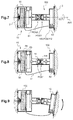
- the figures 2 , 5 to 12 explain the operation of the fixing device.
- the movable stud With reference to the figure 2 before the connection of the movable stud 10 to the fixed stud 100, the movable stud is in its engagement position.
- the reel, the first arm, the first ball and the first magnetization means are each positioned as far as possible from the panel 2.
- the fixed stud is in its disengaged position.
- the second arm, the second ball and the second magnetization means are each positioned as close as possible to the structure 3.
- the operator operates the cable 36 which induces a translation of the first rack 40 according to the arrow F3.
- This translation generates a rotation of the first arm 31 according to the arrow F4.
- the presence of the first nut therefore induces the translation of the first arm, the first ball and the first magnetization means according to the arrow F5.
- the first base 31 "exerts a force on the reel 55 allowing the longitudinal displacement of this reel by compressing the spring member 60.
- the reel, the first arm, the first ball and the first magnetization means are each positioned in the disengagement position as close as possible to the panel 2.
- the operator inserts the tool 38 through the panel 2 in the movable stud. With this tool, the operator then directly rotates the first arm.
- the reel 55 is not blocked by the notches 65 of the first housing, this operator can indeed unroll the safety link to manipulate the ball pin.
- the first magnetization means remains in its disengagement position.
- the operator By releasing the safety link, the operator allows the spring member to rotate the reel to rewind the safety link.
- the mobile stud then attaches to the fixed stud.
- the operator then uses a drive means of the movable stud to join the first magnetization means 15 against the second magnetization means 115 of the fixed stud.
- the mobile stud is then magnetized to the fixed stud which allows to fix the panel 2 to the structure 3.
- the arrangement of the magnetization means on at least one ball joint makes it possible to allow an angular offset between the panel 2 and the structure 3.
- this arrangement makes it possible to allow an axial offset between the panel 2 and the structure 3.
- the magnetization power of the magnetization means of the mobile and fixed studs may be insufficient to maintain the panel against the structure 3.
- This panel then pivots with respect to the structure 3. However, the reel of the movable stud being blocked by the first housing, this rotary movement is interrupted by the safety link 51.
Landscapes
- Engineering & Computer Science (AREA)
- General Engineering & Computer Science (AREA)
- Mechanical Engineering (AREA)
- Aviation & Aerospace Engineering (AREA)
- Physics & Mathematics (AREA)
- Electromagnetism (AREA)
- Power Engineering (AREA)
- Pivots And Pivotal Connections (AREA)
- Details Of Spanners, Wrenches, And Screw Drivers And Accessories (AREA)
Claims (20)
- Befestigungsvorrichtung (5) zum Befestigen einer Platte (2) an einer Struktur (3), wobei die Befestigungsvorrichtung (5) mit mindestens einer lösbaren Befestigungseinheit (7) versehen ist, die einen beweglichen Klotz (10) aufweist, der an der Platte (2) befestigt werden kann, und einen fest angebrachten Klotz (100), der auf der Struktur (3) befestigt werden kann, wobei der bewegliche Klotz (10) ein erstes Magnetisierungsmittel (15) aufweist, das mit einem zweiten Magnetisierungsmittel (115) des fest angebrachten Klotzes (100) zusammenwirkt, wobei mindestens eines des ersten Magnetisierungsmittels (15) und des zweiten Magnetisierungsmittels (115) einen Magneten (16) aufweist,
dadurch gekennzeichnet, dass mindestens ein Magnetisierungsmittel (15, 115) von einem Kugelgelenk (20, 200) des zugehörigen Klotzes getragen wird, wobei jedes Magnetisierungsmittel (15, 115) in Translationsrichtung fest mit einem Bewegungsmittel (30, 300) verbunden ist, um in Translationsrichtung entlang einer Längsachse (AX1, AX100) des zugehörigen Klotzes aus einer Eingriffsstellung (POS 1) in eine Entkopplungsstellung (POS2) umkehrbar bewegt zu werden, wobei die Längsachse (AX1) des beweglichen Klotzes "erste Längsachse" genannt wird und im Wesentlichen parallel zu einer Längsachse (AX100) des fest angebrachten Klotzes, genannt "zweite Längsachse", ist, wobei die Magnetisierungsmittel (15, 155) zueinander stark magnetisiert sind, wenn sie sich gegenüberliegen und beide in Eingriffsstellung (POS1) sind, und wobei diese nicht magnetisiert oder schwach magnetisiert sind, wenn mindestens eines der Magnetisierungsmittel (15, 115) sich in seiner Entkopplungsstellung (POS2) befindet. - Vorrichtung nach Anspruch 1,
dadurch gekennzeichnet, dass die Befestigungsvorrichtung (5) mindestens ein Schwenkgelenk (6) aufweist, das an der Platte (2) und an der Struktur (3) befestigt werden kann, um eine Drehung der Platte (2) relativ zu der Struktur (3) zu ermöglichen. - Vorrichtung nach einem der Ansprüche 1 bis 2,
dadurch gekennzeichnet, dass entweder jedes Magnetisierungsmittel (15, 115) einen Magneten (16) aufweist, oder ein Magnetisierungsmittel (15) einen Magneten (16) aufweist, und das andere Magnetisierungsmittel (115) eine Metallplatte (116) aufweist. - Vorrichtung nach einem der Ansprüche 1 bis 3,
dadurch gekennzeichnet, dass mindestens ein Magnetisierungsmittel (15) eine "Verbindungsfläche (17)" genannte Fläche aufweist zur Magnetisierung des anderen Magnetisierungsmittels (115), wobei die Verbindungsfläche (17) mit einem Gleitorgan (18) bedeckt ist. - Vorrichtung nach einem der Ansprüche 1 bis 4,
dadurch gekennzeichnet, dass mindestens ein Klotz (10, 100) ein Bewegungsmittel (30, 300) aufweist, das mit einem Arm (31, 131) versehen ist, wobei der Arm (31, 131) eine Endlosschraube (32, 132) aufweist, die in eine Schraubenmutter (33, 133) eingreift, die an einem Gehäuse des Klotzes (10, 100) befestigt ist, wobei das Bewegungsmittel (30, 300) mit einem Antriebsmittel (35, 135) versehen ist, um den Arm (31, 131) zu drehen, um die Translationsbewegung des Arms (31, 131) auszulösen. - Vorrichtung nach Anspruch 5,
dadurch gekennzeichnet, dass der Arm (31, 131) sich in Längsrichtung von einem Ende (31', 131'), das mit einem Magnetisierungsmittel verbunden ist, zu einem Ende (31", 131") erstreckt, das mit einer Zahnbasis versehen ist, wobei das Antriebsmittel (35, 135) ein in Querrichtung bewegliches Zahngestänge (40, 140) aufweist, wobei ein Rand der Basis (31", 131") mindestens teilweise gezahnt ist, indem er mindestens einen Zahn (34,134) aufweist, der in Eingriff mit dem Zahngestänge (40, 140) steht. - Vorrichtung nach Anspruch 6,
dadurch gekennzeichnet, dass das Antriebsmittel (35) des beweglichen Klotzes (10) ein Kabel (36) aufweist, das mit dem Zahngestänge (40) fest verbunden ist. - Vorrichtung nach einem der Ansprüche 5 bis 7,
dadurch gekennzeichnet, dass das Antriebsmittel (35) des beweglichen Klotzes (10) eine Öffnung (37) des Arms (31) aufweist, das den Kopf eines Verschraub-/Abschraubwerkzeugs (38) aufnehmen kann, wobei ein Gehäuse (11) des beweglichen Klotzes (10) einen Durchgang (39) aufweist, um ein solches Werkzeug (38) zu der Öffnung (37) zu führen. - Vorrichtung nach einem der Ansprüche 1 bis 8,
dadurch gekennzeichnet, dass die Befestigungsvorrichtung (5) ein Crash-Sicherheitssystem (50) aufweist, das mit einem Sicherheitsband (51) versehen ist, welches auf einem Aufroller (55) aufgerollt ist, der den beweglichen Klotz (10) selbstblockierend sperrt, wobei das Sicherheitsband (51) einen Kugelsperrbolzen (53) aufweist, der reversibel und manuell in das Gehäuse (150) des fest angebrachten Klotzes (100) einfügbar ist. - Vorrichtung nach Anspruch 9,
dadurch gekennzeichnet, dass der Aufroller (55) in Translationsrichtung entlang der ersten Längsachse (AX1) des beweglichen Klotzes (10) beweglich ist, indem er um ein Führungsmittel (14) eines Gehäuses (11) des beweglichen Klotzes (10) angeordnet ist, wobei der Aufroller (55) durch ein Federelement (60) gegen das Bewegungsmittel (30) angedrückt ist, um in Translationsrichtung des Magnetisierungsmittels (15) des beweglichen Klotzes (10) fest verbunden zu sein. - Vorrichtung nach einem der Ansprüche 9 bis 10,
dadurch gekennzeichnet, dass das Gehäuse (11) mindestens einen Zahn (65) aufweist, der mit einer gezahnten Fläche (55') des Aufrollers (55) zusammenwirkt, um eine Drehung des Aufrollers (55) in einer Abroll-Drehrichtung (S1) zu verhindern, die das Abzurollen des Sicherheitsbandes (51) ermöglicht, wenn das Magnetisierungsmittel sich in seiner Eingriffsstellung (POS1) befindet. - Vorrichtung nach einem der Ansprüche 9 bis 11,
dadurch gekennzeichnet, dass das Gehäuse (150) von einem Finger (141) eines Zahngestänges (140) durchquert wird, der mit dem Bewegungsmittel (300) des fest angebrachten Klotzes (100) in Abwesenheit des Kugelsperrbolzens (53) in Eingriff steht, wobei das Magnetisierungsmittel (115) des fest angebrachten Klotzes (100) sich in Abwesenheit des Kugelsperrbolzens (53) in der ausgerückten Stellung (POS2) befindet. - Vorrichtung nach einem der Ansprüche 9 bis 12,
dadurch gekennzeichnet, dass der Aufroller (55) eine Rückholfeder (70) aufweist, die eine Drehung des Aufrollers in einer Aufrollrichtung (S2) erzeugt, um das Sicherheitsband (51) auf dem Aufroller (55) aufzurollen. - Vorrichtung nach einem der Ansprüche 1 bis 13,
dadurch gekennzeichnet, dass der bewegliche Klotz (10) ein "erstes Zahngestänge (40)" genanntes Zahngestänge aufweist, das mit dem Bewegungsmittel des beweglichen Klotzes, welches "erstes Bewegungsmittel (30)" genannt wird, zusammenwirkt, wobei das erste Zahngestänge (40) beweglich ist zwischen einer ersten Stellung (POS11), die das Magnetisierungsmittel (15) des beweglichen Klotzes (10) in die Eingriffsstellung (POS1) verbringt, und einer zweiten Stellung (POS 12), die das Magnetisierungsmittel (15) des beweglichen Klotzes (10) in die Ausrückstellung (POS2) verbringt, wobei der bewegliche Klotz (10) ein erstes Federelement (42) aufweist, das eine Kraft ausübt, um das erste Zahngestänge (40) in die erste Stellung (POS11) zu verbringen. - Vorrichtung nach einem der Ansprüche 1 bis 14,
dadurch gekennzeichnet, dass der fest angebrachte Klotz (100) ein "zweites Zahngestänge (140)" genanntes Zahngestänge aufweist, das mit dem Bewegungsmittel des fest angebrachten Klotzes, welches "zweites Bewegungsmittel (300)" genannt wird, zusammenwirkt, wobei das zweite Zahngestänge (140) beweglich ist zwischen einer ersten Stellung (POS111), die das Magnetisierungsmittel (115) des fest angebrachten Klotzes (100) in die Eingriffsstellung (POS 1) verbringt, und einer zweiten Stellung (POS112), die das Magnetisierungsmittel (115) des fest angebrachten Klotzes (100) in die Ausrückstellung (POS2) verbringt, wobei der fest angebrachte Klotz (100) ein zweites Federelement (142) aufweist, das eine Kraft ausübt zur Positionierung des zweiten Zahngestänges (140) in seiner zweiten Stellung (POS 112). - Vorrichtung nach einem der Ansprüche 1 bis 15,
dadurch gekennzeichnet, dass der bewegliche Klotz (10) ein erstes Magnetisierungsmittel (15) aufweist, das von einem ersten Bewegungsmittel (30) getragen wird, wobei das erste Bewegungsmittel (30) einen Rahmen (31) aufweist, der mit dem ersten Magnetisierungsmittel sowie mit einer ersten Basis (31") verbunden ist, und wobei eine erste Endlosschraube (32) sich zwischen dem ersten Magnetisierungsmittel und der ersten Basis (31") erstreckt, indem sie eine erste fest angebrachte Schraubenmutter (33) durchquert, wobei die erste Basis (31") Zähne (34) aufweist, die in Eingriff mit einem ersten Zahngestänge (40) stehen, wobei der bewegliche Klotz (10) einen Aufroller (55) aufweist, auf dem ein Sicherheitsband (51) aufgerollt ist, das einen Kugelsperrbolzen (53) aufweist, wobei der Aufroller (55) in Translationsrichtung entlang einer ersten Längsachse (AX1) des beweglichen Klotzes (10) beweglich ist und von einem ersten Federelement (42) gegen das erste Bewegungsmittel (30) angedrückt wird, damit dieses in Translationsrichtung des ersten Magnetisierungsmittels (15) mit dem beweglichen Klotz (10) fest verbunden ist, wobei der Aufroller (55) eine gezahnte Fläche (55') aufweist, die in Eingriff mit mindestens einem Zahn (65) eines Gehäuses (11) des beweglichen Klotzes (10) in der Eingriffsstellung (POS1) steht. - Vorrichtung nach einem der Ansprüche 1 bis 16,
dadurch gekennzeichnet, dass der fest angebrachte Klotz (100) ein zweites Magnetisierungsmittel (115) aufweist, das von einem zweiten Bewegungsmittel (300) getragen wird, wobei das zweite Bewegungsmittel (300) einen Arm (131) aufweist, der mit dem zweiten Magnetisierungsmittel sowie mit einer zweiten Basis (131") verbunden ist, und eine zweite Endlosschraube (132), die sich zwischen dem zweiten Kugelgelenk (200) und der zweiten Basis (131") erstreckt, indem sie eine zweite fest angebrachte Schraubenmutter (133) durchquert, wobei die zweite Basis (131") Zähne (134) aufweist, die in Eingriff mit einem zweiten Zahngestänge (140) stehen, wobei das zweite Zahngestänge (140) ein Gehäuse (150) aufweist, in das ein Kugelsperrbolzen (53) des beweglichen Klotzes (10) eingesteckt werden kann. - Vorrichtung nach einem der Ansprüche 1 bis 17,
dadurch gekennzeichnet, dass die Befestigungsvorrichtung (5) ein Element aus einem Elastomer (80, 180) aufweist, das zwischen dem Magnetisierungsmittel eines Klotzes (10, 100) und einem Gehäuse (11, 111) dieses Klotzes (10, 100) angeordnet ist, entweder zwischen einem Kugelgelenk und dem Gehäuse oder zwischen dem Bewegungsmittel (30, 300) und dem Gehäuse (11, 111). - Vorrichtung nach einem der Ansprüche 1 bis 18,
dadurch gekennzeichnet, dass jedes Magnetisierungsmittel von einem Kugelgelenk getragen wird. - Luftfahrzeug (1) mit einer Struktur und mindestens einer Verkleidungsplatte,
dadurch gekennzeichnet, dass dieses Luftfahrzeug (1) mindestens eine Befestigungsvorrichtung (5) nach einem der Ansprüche 1 bis 19 aufweist.
Applications Claiming Priority (1)
| Application Number | Priority Date | Filing Date | Title |
|---|---|---|---|
| FR1401059A FR3020796B1 (fr) | 2014-05-12 | 2014-05-12 | Dispositif de fixation pour fixer un panneau a une structure, et aeronef |
Publications (2)
| Publication Number | Publication Date |
|---|---|
| EP2944751A1 EP2944751A1 (de) | 2015-11-18 |
| EP2944751B1 true EP2944751B1 (de) | 2016-10-19 |
Family
ID=51167979
Family Applications (1)
| Application Number | Title | Priority Date | Filing Date |
|---|---|---|---|
| EP15165270.8A Active EP2944751B1 (de) | 2014-05-12 | 2015-04-27 | Befestigungsvorrichtung zum befestigen eines paneels an eine struktur, und luftfahrzeug |
Country Status (4)
| Country | Link |
|---|---|
| US (1) | US9752601B2 (de) |
| EP (1) | EP2944751B1 (de) |
| CN (1) | CN105083524B (de) |
| FR (1) | FR3020796B1 (de) |
Families Citing this family (9)
| Publication number | Priority date | Publication date | Assignee | Title |
|---|---|---|---|---|
| US10371185B2 (en) | 2017-01-09 | 2019-08-06 | David Lynn | Magnetically-controlled connectors and methods of use |
| CN109421913B (zh) * | 2017-08-30 | 2025-02-14 | 深圳市道通智能航空技术股份有限公司 | 可折叠的机架和无人机 |
| US10651786B2 (en) | 2018-01-08 | 2020-05-12 | David Lynn | Panel with magnetically-controlled connectors for attachment to a support member |
| US10971870B2 (en) | 2018-08-17 | 2021-04-06 | David Lynn | Connection interface for a panel and support structure |
| GB2577540A (en) * | 2018-09-28 | 2020-04-01 | Airbus Operations Ltd | Joint for connecting aircraft structures |
| GB2580980A (en) * | 2019-02-04 | 2020-08-05 | Airbus Operations Ltd | Interfaces between components |
| KR20230103067A (ko) * | 2021-12-31 | 2023-07-07 | 엘지디스플레이 주식회사 | 간격조절부재 및 이를 포함하는 고정장치 |
| US12539968B2 (en) | 2022-07-06 | 2026-02-03 | B/E Aerospace, Inc. | Self-locking mounting insert |
| GB2637951B (en) * | 2024-02-07 | 2026-04-22 | Bae Systems Plc | Structural assemblies for aircraft |
Family Cites Families (15)
| Publication number | Priority date | Publication date | Assignee | Title |
|---|---|---|---|---|
| DE145325C (de) * | 1902-12-30 | 1905-11-25 | ||
| US2970857A (en) * | 1957-07-24 | 1961-02-07 | Midwest Mfg Company | Magnetic door latch |
| GB1056797A (en) * | 1963-10-08 | 1967-01-25 | John Wright And Sons Veneers L | Securing panelling magnetically |
| US4585197A (en) * | 1983-09-06 | 1986-04-29 | James P. Liautaud | Swivel base assembly |
| US5280991A (en) | 1992-02-19 | 1994-01-25 | Prince Corporation | Headliner |
| US6857809B2 (en) | 2001-03-30 | 2005-02-22 | Robert Granata | Articulating fastener assembly |
| US7178207B2 (en) | 2003-04-11 | 2007-02-20 | Sheung Chung Wong | Magnetic fastener |
| US7422403B1 (en) * | 2003-10-23 | 2008-09-09 | Tini Alloy Company | Non-explosive releasable coupling device |
| DE202004001958U1 (de) | 2004-02-09 | 2005-06-30 | Drumm Gmbh | Magneto-mechanische Schließeinrichtung II |
| JP5095278B2 (ja) * | 2006-08-10 | 2012-12-12 | 株式会社日立製作所 | 半導体デバイス歩留り予測システムおよび方法 |
| DE102006060074B4 (de) * | 2006-12-19 | 2014-07-10 | Airbus Operations Gmbh | Halterungsvorrichtung |
| US8555468B2 (en) | 2008-02-25 | 2013-10-15 | Illinois Tool Works Inc. | Anti-rattle carrier for magnet fastener |
| DE102009026250B4 (de) * | 2009-07-24 | 2014-05-28 | Sfs Intec Holding Ag | Befestigungssystem für hängend montierbare Deckencontainer |
| EP2415662B1 (de) | 2010-08-02 | 2012-07-18 | Eurocopter Deutschland GmbH | Rumpfstruktur aus Verbundwerkstoff |
| ITBO20120574A1 (it) * | 2012-10-22 | 2014-04-23 | Riri Sa | Componente femmina di un bottone automatico, procedimento per la sua fabbricazione nonché bottone automatico comprendente tale componente femmina |
-
2014
- 2014-05-12 FR FR1401059A patent/FR3020796B1/fr active Active
-
2015
- 2015-04-27 EP EP15165270.8A patent/EP2944751B1/de active Active
- 2015-05-05 US US14/704,228 patent/US9752601B2/en not_active Expired - Fee Related
- 2015-05-12 CN CN201510238955.5A patent/CN105083524B/zh not_active Expired - Fee Related
Also Published As
| Publication number | Publication date |
|---|---|
| US20150322979A1 (en) | 2015-11-12 |
| CN105083524B (zh) | 2017-04-12 |
| FR3020796A1 (fr) | 2015-11-13 |
| US9752601B2 (en) | 2017-09-05 |
| FR3020796B1 (fr) | 2016-06-10 |
| CN105083524A (zh) | 2015-11-25 |
| EP2944751A1 (de) | 2015-11-18 |
Similar Documents
| Publication | Publication Date | Title |
|---|---|---|
| EP2944831B1 (de) | Befestigungsvorrichtung zum befestigen eines paneels an eine struktur, und luftfahrzeug | |
| EP2944751B1 (de) | Befestigungsvorrichtung zum befestigen eines paneels an eine struktur, und luftfahrzeug | |
| EP3405633B1 (de) | Externe öffnungssteuerung eines kraftfahrzeugs | |
| EP3145763B1 (de) | Elektromotorbremse und elektrische maschine mit so einer bremse | |
| CA2798465C (fr) | Boitier d'accrochage a actionneur a came d'encombrement reduit | |
| EP3003863A1 (de) | Vorrichtung zum abtasten eines raumobjekts mit einem druckelement und mindestens zwei wiederverschliessbaren elementen auf dem raumobjekt | |
| FR3003510A1 (fr) | Arret de gaine pivotant pour gaine, support, rail de guidage, ensemble, leve-vitre, procede de montage correspondants | |
| FR2982585A1 (fr) | Compartiment a bagages pour avion et avion le comportant | |
| FR3072707A1 (fr) | Vehicule muni d'une porte coulissante. | |
| FR2932164A1 (fr) | Dispositif de maintien d'au moins un objet mobile, reutilisable, securise autonome et sans chocs, pour engins spatiaux | |
| EP2930104A1 (de) | Verfahren zur bedienung der ladegutklappen eines luftfahrzeugs, und dazu verwendetes stellglied | |
| FR2942156A3 (fr) | Poste de montage d'un vehicule automobile comportant un robot muni d'un organe de prehension | |
| WO2015110365A1 (fr) | Dispositif de blocage en rotation a structure simplifiee et actionneur comprenant un tel dispositif | |
| FR2864221A1 (fr) | Charge largable a partir d'un aeronef comprenant un dispositif de securite | |
| FR3011204A1 (fr) | Procede de gestion d'une deformation programmee d'un vehicule automobile lors d'un choc frontal et vehicule automobile comportant des moyens pour sa mise en œuvre | |
| FR2987013A1 (fr) | Dispositif pour l'ancrage d'un pene de ceinture de securite de vehicule, a moyens d'immobilisation facilitant sa fixation | |
| EP4159616B1 (de) | Hindernis zum sichern eines luftfahrzeugs auf einem landegitter und luftfahrzeug | |
| EP3921230B1 (de) | Auswurfsystem für einen notausstieg eines fahrzeugs | |
| FR3110664A3 (fr) | Système de fixation à gestion de mobilité déporté pour au moins un lien de communication et véhicule | |
| FR3014774A1 (fr) | Dispositif de fixation d'une commande de boite de vitesses et procede de montage associe | |
| FR2965002A1 (fr) | Dispositif de verrouillage pour ensemble d'obturation coulissant | |
| WO2005090718A1 (fr) | Systeme d’ouverture/fermeture d’une porte permettant l’acces entre la cabine passagers et le cockpit d’un avion | |
| FR3056187B1 (fr) | Chariot autopropulse | |
| FR2928108A1 (fr) | Dispositif de verrouillage pour toit mobile de vehicule automobile | |
| FR3013280A1 (fr) | Rangement nomade pour vehicule |
Legal Events
| Date | Code | Title | Description |
|---|---|---|---|
| PUAI | Public reference made under article 153(3) epc to a published international application that has entered the european phase |
Free format text: ORIGINAL CODE: 0009012 |
|
| AK | Designated contracting states |
Kind code of ref document: A1 Designated state(s): AL AT BE BG CH CY CZ DE DK EE ES FI FR GB GR HR HU IE IS IT LI LT LU LV MC MK MT NL NO PL PT RO RS SE SI SK SM TR |
|
| AX | Request for extension of the european patent |
Extension state: BA ME |
|
| 17P | Request for examination filed |
Effective date: 20160111 |
|
| RBV | Designated contracting states (corrected) |
Designated state(s): AL AT BE BG CH CY CZ DE DK EE ES FI FR GB GR HR HU IE IS IT LI LT LU LV MC MK MT NL NO PL PT RO RS SE SI SK SM TR |
|
| GRAP | Despatch of communication of intention to grant a patent |
Free format text: ORIGINAL CODE: EPIDOSNIGR1 |
|
| RIC1 | Information provided on ipc code assigned before grant |
Ipc: F16B 5/06 20060101ALI20160601BHEP Ipc: H01F 7/02 20060101ALI20160601BHEP Ipc: E05C 19/16 20060101AFI20160601BHEP |
|
| INTG | Intention to grant announced |
Effective date: 20160628 |
|
| GRAS | Grant fee paid |
Free format text: ORIGINAL CODE: EPIDOSNIGR3 |
|
| GRAA | (expected) grant |
Free format text: ORIGINAL CODE: 0009210 |
|
| AK | Designated contracting states |
Kind code of ref document: B1 Designated state(s): AL AT BE BG CH CY CZ DE DK EE ES FI FR GB GR HR HU IE IS IT LI LT LU LV MC MK MT NL NO PL PT RO RS SE SI SK SM TR |
|
| REG | Reference to a national code |
Ref country code: GB Ref legal event code: FG4D Free format text: NOT ENGLISH |
|
| REG | Reference to a national code |
Ref country code: CH Ref legal event code: EP |
|
| REG | Reference to a national code |
Ref country code: AT Ref legal event code: REF Ref document number: 838501 Country of ref document: AT Kind code of ref document: T Effective date: 20161115 |
|
| REG | Reference to a national code |
Ref country code: IE Ref legal event code: FG4D Free format text: LANGUAGE OF EP DOCUMENT: FRENCH |
|
| REG | Reference to a national code |
Ref country code: DE Ref legal event code: R096 Ref document number: 602015000506 Country of ref document: DE |
|
| REG | Reference to a national code |
Ref country code: NL Ref legal event code: MP Effective date: 20161019 |
|
| REG | Reference to a national code |
Ref country code: LT Ref legal event code: MG4D |
|
| PG25 | Lapsed in a contracting state [announced via postgrant information from national office to epo] |
Ref country code: LV Free format text: LAPSE BECAUSE OF FAILURE TO SUBMIT A TRANSLATION OF THE DESCRIPTION OR TO PAY THE FEE WITHIN THE PRESCRIBED TIME-LIMIT Effective date: 20161019 |
|
| REG | Reference to a national code |
Ref country code: AT Ref legal event code: MK05 Ref document number: 838501 Country of ref document: AT Kind code of ref document: T Effective date: 20161019 |
|
| REG | Reference to a national code |
Ref country code: FR Ref legal event code: PLFP Year of fee payment: 3 |
|
| PG25 | Lapsed in a contracting state [announced via postgrant information from national office to epo] |
Ref country code: SE Free format text: LAPSE BECAUSE OF FAILURE TO SUBMIT A TRANSLATION OF THE DESCRIPTION OR TO PAY THE FEE WITHIN THE PRESCRIBED TIME-LIMIT Effective date: 20161019 Ref country code: NO Free format text: LAPSE BECAUSE OF FAILURE TO SUBMIT A TRANSLATION OF THE DESCRIPTION OR TO PAY THE FEE WITHIN THE PRESCRIBED TIME-LIMIT Effective date: 20170119 Ref country code: LT Free format text: LAPSE BECAUSE OF FAILURE TO SUBMIT A TRANSLATION OF THE DESCRIPTION OR TO PAY THE FEE WITHIN THE PRESCRIBED TIME-LIMIT Effective date: 20161019 Ref country code: GR Free format text: LAPSE BECAUSE OF FAILURE TO SUBMIT A TRANSLATION OF THE DESCRIPTION OR TO PAY THE FEE WITHIN THE PRESCRIBED TIME-LIMIT Effective date: 20170120 |
|
| PG25 | Lapsed in a contracting state [announced via postgrant information from national office to epo] |
Ref country code: NL Free format text: LAPSE BECAUSE OF FAILURE TO SUBMIT A TRANSLATION OF THE DESCRIPTION OR TO PAY THE FEE WITHIN THE PRESCRIBED TIME-LIMIT Effective date: 20161019 Ref country code: FI Free format text: LAPSE BECAUSE OF FAILURE TO SUBMIT A TRANSLATION OF THE DESCRIPTION OR TO PAY THE FEE WITHIN THE PRESCRIBED TIME-LIMIT Effective date: 20161019 Ref country code: HR Free format text: LAPSE BECAUSE OF FAILURE TO SUBMIT A TRANSLATION OF THE DESCRIPTION OR TO PAY THE FEE WITHIN THE PRESCRIBED TIME-LIMIT Effective date: 20161019 Ref country code: AT Free format text: LAPSE BECAUSE OF FAILURE TO SUBMIT A TRANSLATION OF THE DESCRIPTION OR TO PAY THE FEE WITHIN THE PRESCRIBED TIME-LIMIT Effective date: 20161019 Ref country code: PT Free format text: LAPSE BECAUSE OF FAILURE TO SUBMIT A TRANSLATION OF THE DESCRIPTION OR TO PAY THE FEE WITHIN THE PRESCRIBED TIME-LIMIT Effective date: 20170220 Ref country code: ES Free format text: LAPSE BECAUSE OF FAILURE TO SUBMIT A TRANSLATION OF THE DESCRIPTION OR TO PAY THE FEE WITHIN THE PRESCRIBED TIME-LIMIT Effective date: 20161019 Ref country code: RS Free format text: LAPSE BECAUSE OF FAILURE TO SUBMIT A TRANSLATION OF THE DESCRIPTION OR TO PAY THE FEE WITHIN THE PRESCRIBED TIME-LIMIT Effective date: 20161019 Ref country code: PL Free format text: LAPSE BECAUSE OF FAILURE TO SUBMIT A TRANSLATION OF THE DESCRIPTION OR TO PAY THE FEE WITHIN THE PRESCRIBED TIME-LIMIT Effective date: 20161019 Ref country code: IS Free format text: LAPSE BECAUSE OF FAILURE TO SUBMIT A TRANSLATION OF THE DESCRIPTION OR TO PAY THE FEE WITHIN THE PRESCRIBED TIME-LIMIT Effective date: 20170219 |
|
| REG | Reference to a national code |
Ref country code: DE Ref legal event code: R097 Ref document number: 602015000506 Country of ref document: DE |
|
| PG25 | Lapsed in a contracting state [announced via postgrant information from national office to epo] |
Ref country code: EE Free format text: LAPSE BECAUSE OF FAILURE TO SUBMIT A TRANSLATION OF THE DESCRIPTION OR TO PAY THE FEE WITHIN THE PRESCRIBED TIME-LIMIT Effective date: 20161019 Ref country code: RO Free format text: LAPSE BECAUSE OF FAILURE TO SUBMIT A TRANSLATION OF THE DESCRIPTION OR TO PAY THE FEE WITHIN THE PRESCRIBED TIME-LIMIT Effective date: 20161019 Ref country code: SK Free format text: LAPSE BECAUSE OF FAILURE TO SUBMIT A TRANSLATION OF THE DESCRIPTION OR TO PAY THE FEE WITHIN THE PRESCRIBED TIME-LIMIT Effective date: 20161019 Ref country code: CZ Free format text: LAPSE BECAUSE OF FAILURE TO SUBMIT A TRANSLATION OF THE DESCRIPTION OR TO PAY THE FEE WITHIN THE PRESCRIBED TIME-LIMIT Effective date: 20161019 Ref country code: DK Free format text: LAPSE BECAUSE OF FAILURE TO SUBMIT A TRANSLATION OF THE DESCRIPTION OR TO PAY THE FEE WITHIN THE PRESCRIBED TIME-LIMIT Effective date: 20161019 |
|
| PLBE | No opposition filed within time limit |
Free format text: ORIGINAL CODE: 0009261 |
|
| STAA | Information on the status of an ep patent application or granted ep patent |
Free format text: STATUS: NO OPPOSITION FILED WITHIN TIME LIMIT |
|
| PG25 | Lapsed in a contracting state [announced via postgrant information from national office to epo] |
Ref country code: BG Free format text: LAPSE BECAUSE OF FAILURE TO SUBMIT A TRANSLATION OF THE DESCRIPTION OR TO PAY THE FEE WITHIN THE PRESCRIBED TIME-LIMIT Effective date: 20170119 Ref country code: SM Free format text: LAPSE BECAUSE OF FAILURE TO SUBMIT A TRANSLATION OF THE DESCRIPTION OR TO PAY THE FEE WITHIN THE PRESCRIBED TIME-LIMIT Effective date: 20161019 |
|
| 26N | No opposition filed |
Effective date: 20170720 |
|
| REG | Reference to a national code |
Ref country code: DE Ref legal event code: R119 Ref document number: 602015000506 Country of ref document: DE |
|
| PG25 | Lapsed in a contracting state [announced via postgrant information from national office to epo] |
Ref country code: SI Free format text: LAPSE BECAUSE OF FAILURE TO SUBMIT A TRANSLATION OF THE DESCRIPTION OR TO PAY THE FEE WITHIN THE PRESCRIBED TIME-LIMIT Effective date: 20161019 |
|
| REG | Reference to a national code |
Ref country code: IE Ref legal event code: MM4A |
|
| PG25 | Lapsed in a contracting state [announced via postgrant information from national office to epo] |
Ref country code: MC Free format text: LAPSE BECAUSE OF FAILURE TO SUBMIT A TRANSLATION OF THE DESCRIPTION OR TO PAY THE FEE WITHIN THE PRESCRIBED TIME-LIMIT Effective date: 20161019 Ref country code: DE Free format text: LAPSE BECAUSE OF NON-PAYMENT OF DUE FEES Effective date: 20171103 |
|
| PG25 | Lapsed in a contracting state [announced via postgrant information from national office to epo] |
Ref country code: LU Free format text: LAPSE BECAUSE OF NON-PAYMENT OF DUE FEES Effective date: 20170427 |
|
| REG | Reference to a national code |
Ref country code: BE Ref legal event code: MM Effective date: 20170430 |
|
| REG | Reference to a national code |
Ref country code: FR Ref legal event code: PLFP Year of fee payment: 4 |
|
| PG25 | Lapsed in a contracting state [announced via postgrant information from national office to epo] |
Ref country code: IE Free format text: LAPSE BECAUSE OF NON-PAYMENT OF DUE FEES Effective date: 20170427 |
|
| PG25 | Lapsed in a contracting state [announced via postgrant information from national office to epo] |
Ref country code: BE Free format text: LAPSE BECAUSE OF NON-PAYMENT OF DUE FEES Effective date: 20170430 |
|
| PG25 | Lapsed in a contracting state [announced via postgrant information from national office to epo] |
Ref country code: MT Free format text: LAPSE BECAUSE OF FAILURE TO SUBMIT A TRANSLATION OF THE DESCRIPTION OR TO PAY THE FEE WITHIN THE PRESCRIBED TIME-LIMIT Effective date: 20161019 |
|
| REG | Reference to a national code |
Ref country code: CH Ref legal event code: PL |
|
| PG25 | Lapsed in a contracting state [announced via postgrant information from national office to epo] |
Ref country code: LI Free format text: LAPSE BECAUSE OF NON-PAYMENT OF DUE FEES Effective date: 20180430 Ref country code: CH Free format text: LAPSE BECAUSE OF NON-PAYMENT OF DUE FEES Effective date: 20180430 |
|
| PG25 | Lapsed in a contracting state [announced via postgrant information from national office to epo] |
Ref country code: HU Free format text: LAPSE BECAUSE OF FAILURE TO SUBMIT A TRANSLATION OF THE DESCRIPTION OR TO PAY THE FEE WITHIN THE PRESCRIBED TIME-LIMIT; INVALID AB INITIO Effective date: 20150427 |
|
| PG25 | Lapsed in a contracting state [announced via postgrant information from national office to epo] |
Ref country code: CY Free format text: LAPSE BECAUSE OF FAILURE TO SUBMIT A TRANSLATION OF THE DESCRIPTION OR TO PAY THE FEE WITHIN THE PRESCRIBED TIME-LIMIT Effective date: 20161019 |
|
| PG25 | Lapsed in a contracting state [announced via postgrant information from national office to epo] |
Ref country code: MK Free format text: LAPSE BECAUSE OF FAILURE TO SUBMIT A TRANSLATION OF THE DESCRIPTION OR TO PAY THE FEE WITHIN THE PRESCRIBED TIME-LIMIT Effective date: 20161019 |
|
| GBPC | Gb: european patent ceased through non-payment of renewal fee |
Effective date: 20190427 |
|
| PG25 | Lapsed in a contracting state [announced via postgrant information from national office to epo] |
Ref country code: GB Free format text: LAPSE BECAUSE OF NON-PAYMENT OF DUE FEES Effective date: 20190427 |
|
| PG25 | Lapsed in a contracting state [announced via postgrant information from national office to epo] |
Ref country code: TR Free format text: LAPSE BECAUSE OF FAILURE TO SUBMIT A TRANSLATION OF THE DESCRIPTION OR TO PAY THE FEE WITHIN THE PRESCRIBED TIME-LIMIT Effective date: 20161019 |
|
| PG25 | Lapsed in a contracting state [announced via postgrant information from national office to epo] |
Ref country code: AL Free format text: LAPSE BECAUSE OF FAILURE TO SUBMIT A TRANSLATION OF THE DESCRIPTION OR TO PAY THE FEE WITHIN THE PRESCRIBED TIME-LIMIT Effective date: 20161019 |
|
| P01 | Opt-out of the competence of the unified patent court (upc) registered |
Effective date: 20230530 |
|
| PGFP | Annual fee paid to national office [announced via postgrant information from national office to epo] |
Ref country code: IT Payment date: 20250424 Year of fee payment: 11 |
|
| PGFP | Annual fee paid to national office [announced via postgrant information from national office to epo] |
Ref country code: FR Payment date: 20250425 Year of fee payment: 11 |