EP2944748B1 - A locking assembly for a ventilating window - Google Patents
A locking assembly for a ventilating window Download PDFInfo
- Publication number
- EP2944748B1 EP2944748B1 EP15165497.7A EP15165497A EP2944748B1 EP 2944748 B1 EP2944748 B1 EP 2944748B1 EP 15165497 A EP15165497 A EP 15165497A EP 2944748 B1 EP2944748 B1 EP 2944748B1
- Authority
- EP
- European Patent Office
- Prior art keywords
- casing
- locking assembly
- window
- actuator slide
- shielding means
- Prior art date
- Legal status (The legal status is an assumption and is not a legal conclusion. Google has not performed a legal analysis and makes no representation as to the accuracy of the status listed.)
- Not-in-force
Links
- 239000000463 material Substances 0.000 claims description 6
- 239000002184 metal Substances 0.000 claims description 6
- 238000004080 punching Methods 0.000 claims description 2
- 238000009423 ventilation Methods 0.000 description 9
- 230000003213 activating effect Effects 0.000 description 2
- 230000004913 activation Effects 0.000 description 1
- 230000000284 resting effect Effects 0.000 description 1
- 230000000717 retained effect Effects 0.000 description 1
- 239000007779 soft material Substances 0.000 description 1
- 238000003466 welding Methods 0.000 description 1
Images


Classifications
-
- E—FIXED CONSTRUCTIONS
- E04—BUILDING
- E04D—ROOF COVERINGS; SKY-LIGHTS; GUTTERS; ROOF-WORKING TOOLS
- E04D13/00—Special arrangements or devices in connection with roof coverings; Protection against birds; Roof drainage; Sky-lights
- E04D13/03—Sky-lights; Domes; Ventilating sky-lights
- E04D13/035—Sky-lights; Domes; Ventilating sky-lights characterised by having movable parts
- E04D13/0351—Sky-lights; Domes; Ventilating sky-lights characterised by having movable parts the parts pivoting about a fixed axis
-
- E—FIXED CONSTRUCTIONS
- E04—BUILDING
- E04D—ROOF COVERINGS; SKY-LIGHTS; GUTTERS; ROOF-WORKING TOOLS
- E04D13/00—Special arrangements or devices in connection with roof coverings; Protection against birds; Roof drainage; Sky-lights
- E04D13/03—Sky-lights; Domes; Ventilating sky-lights
- E04D13/0325—Sky-lights; Domes; Ventilating sky-lights provided with ventilating means
-
- E—FIXED CONSTRUCTIONS
- E05—LOCKS; KEYS; WINDOW OR DOOR FITTINGS; SAFES
- E05C—BOLTS OR FASTENING DEVICES FOR WINGS, SPECIALLY FOR DOORS OR WINDOWS
- E05C17/00—Devices for holding wings open; Devices for limiting opening of wings or for holding wings open by a movable member extending between frame and wing; Braking devices, stops or buffers, combined therewith
- E05C17/02—Devices for holding wings open; Devices for limiting opening of wings or for holding wings open by a movable member extending between frame and wing; Braking devices, stops or buffers, combined therewith by mechanical means
- E05C17/04—Devices for holding wings open; Devices for limiting opening of wings or for holding wings open by a movable member extending between frame and wing; Braking devices, stops or buffers, combined therewith by mechanical means with a movable bar or equivalent member extending between frame and wing
- E05C17/12—Devices for holding wings open; Devices for limiting opening of wings or for holding wings open by a movable member extending between frame and wing; Braking devices, stops or buffers, combined therewith by mechanical means with a movable bar or equivalent member extending between frame and wing consisting of a single rod
- E05C17/24—Devices for holding wings open; Devices for limiting opening of wings or for holding wings open by a movable member extending between frame and wing; Braking devices, stops or buffers, combined therewith by mechanical means with a movable bar or equivalent member extending between frame and wing consisting of a single rod pivoted at one end, and with the other end running along a guide member
- E05C17/28—Devices for holding wings open; Devices for limiting opening of wings or for holding wings open by a movable member extending between frame and wing; Braking devices, stops or buffers, combined therewith by mechanical means with a movable bar or equivalent member extending between frame and wing consisting of a single rod pivoted at one end, and with the other end running along a guide member with braking, clamping or securing means at the connection to the guide member
-
- E—FIXED CONSTRUCTIONS
- E06—DOORS, WINDOWS, SHUTTERS, OR ROLLER BLINDS IN GENERAL; LADDERS
- E06B—FIXED OR MOVABLE CLOSURES FOR OPENINGS IN BUILDINGS, VEHICLES, FENCES OR LIKE ENCLOSURES IN GENERAL, e.g. DOORS, WINDOWS, BLINDS, GATES
- E06B7/00—Special arrangements or measures in connection with doors or windows
- E06B7/02—Special arrangements or measures in connection with doors or windows for providing ventilation, e.g. through double windows; Arrangement of ventilation roses
- E06B7/10—Special arrangements or measures in connection with doors or windows for providing ventilation, e.g. through double windows; Arrangement of ventilation roses by special construction of the frame members
-
- E—FIXED CONSTRUCTIONS
- E05—LOCKS; KEYS; WINDOW OR DOOR FITTINGS; SAFES
- E05B—LOCKS; ACCESSORIES THEREFOR; HANDCUFFS
- E05B15/00—Other details of locks; Parts for engagement by bolts of fastening devices
- E05B15/0086—Toggle levers
-
- E—FIXED CONSTRUCTIONS
- E05—LOCKS; KEYS; WINDOW OR DOOR FITTINGS; SAFES
- E05B—LOCKS; ACCESSORIES THEREFOR; HANDCUFFS
- E05B17/00—Accessories in connection with locks
- E05B17/0045—Silencing devices; Noise reduction
Definitions
- the present invention relates to a locking assembly for a ventilating window having a sash arranged to be openable with respect to a main frame by pivotal movement about an axis parallel to a pair of opposed sash members, said locking assembly comprising a strike plate fixed to a main frame member opposite one of said pair of sash members and a casing fixed to said one sash member opposite the strike plate, a locking mechanism arranged in said casing being operable by an operator member accessible from the inside of the window via at least one actuator slide displaceable in guide means in the casing between a first end position defining the unlocked position and a second end position defining the locked position.
- a locking assembly of the above-mentioned type is disclosed in DK-C-114 046 .
- An actuator slide protruding through the casing connects the operator member with the locking mechanism, said actuator slide having a first, unlocked position, a second, locked position and a third, intermediate position where the window is slightly open to achieve ventilation.
- Also protruding through slots in the casing are two pawl members. When closing the window the pawl members come into engagement with the fixed strike plate whereby they are forced to the sides and the actuator slide is pressed into its second position. For the purpose of ventilation, the actuator slide is pulled half way back towards the first position by use of the operator member without the pawl members being displaced.
- the above-described locking assembly works very well, but there is a risk that unauthorized access to the inside of the building may be obtained by introducing a flat, stiff object from the outside of the window into the slit between the sash and frame then pushing the actuator slide to its first, unlocked position.
- WO 99/51832 discloses an insert member projecting from the frame towards the sash thus filling the majority of the space between the two and making it more difficult to reach the actuator slide.
- the primary purpose of the insert member is to reduce the height of the ventilation passage.
- the insert member therefore extends along the entire length of the frame member and has a recess to make room for the locking mechanism thus giving the weakest protection in the area where it is most needed.
- the object is achieved with a locking assembly according to claim 1.
- the shielding means can be arranged between the actuator slide and the outside of the window. No extra parts have to be added to the locking assembly and the adding of the shielding means does therefore not complicate the mounting of the locking assembly. Inserts in the guide means may be used for the purpose of hindering noise and wear otherwise caused by metal-to-metal contact between the actuator slide and the casing. Adding the shielding means in this way does therefore not mean the adding of extra parts either and the abovementioned advantages of making the shielding means part of an existing part are retained.
- the shielding means consist of more than one part, preferably a part of the casing as well as a part of an insert in the guide means.
- the shielding means consists of different materials. For instance soft material may be used where the use of a harder one would cause unwanted noise.
- Figs. 1 and 2 show perspective views of a prior art locking assembly.
- the locking assembly is mounted in a ventilating window.
- a casing 102 encases a locking mechanism and comprises fastening holes 55 for mounting the locking assembly to a top sash member 2 (cf. figs. 3 and 4 ) of a window sash.
- Pawls 11 and actuator slide 13 extend through first and second slots 12 and 14, respectively, in the casing and fastening pins 30 are used for fastening the locking mechanism in the casing 102.
- Slots 12, 14 in the casing serve as first and second guide means, respectively.
- the actuator slide 13 is preferably mounted with a friction plate 50 and an operator arm 20 mounted with a hinge pin 25 to the part of the actuator slide 13 that extends through the casing 102.
- the operator arm 20 is to be mounted to an operator member 4 (cf. figs. 3 and 4 ) by means of an operator hinge 10 with fastening holes.
- the locking mechanism shown in fig. 2 comprises first arms 60 with cutouts 65, second arms 62 connected in one piece to the pawls 11, first spring wires 64, second spring wires 66, the actuator slide 13 and first, second and third arm hinges 70, 72, 74.
- Said actuator slide 13 is moveable between three resting positions; a first, unlocked position in which the window is open or can be opened without activating the locking assembly ( figs. 1, 2 and 4 ), a second, locked position in which the window is locked in a closed position (not shown) and a third, intermediate position where the window is slightly open to achieve ventilation ( fig. 3 ).
- the actuator slide 13 and the pawls 11 are interconnected via the locking mechanism, which comprises a system of the second and the first spring-loaded arms 60, 62 and the first and the second spring wires 64, 66, which force actuator slide 13 to move stepwise between said three positions while the pawls 11 only move between a locked pawl position and an unlocked pawl position.
- the pawls 11 are shown in the unlocked pawl position.
- the locking mechanism operates symmetrically around the slot 14 and the actuator slide 13.
- the first arms 60 of the locking mechanism are connected to the actuator slide 13 via the first arm hinge 70 and to the second arms 62 via the second arm hinge 72.
- the second arms 62 of the locking mechanism are fastened to the casing 102 via the third arm hinge 74.
- the first spring wires 64 are mounted to the casing 102 via fastening pin heads 31 and fastened to the second arm hinges 72, and the second spring wires 66 are mounted on the first arms 60 and fastened to the first arm hinge 70.
- the actuator slide 13 and the pawls 11 are positioned at the other ends of slots 14 and 12, respectively, compared to the position in figs. 1 and 2 .
- the actuator slide 13 is held in the first, unlocked position by the second spring wires 66 and a first dead point of the locking mechanism.
- the actuator slide 13 is moved from the second, locked position to the third, intermediate position by moving the actuator slide 13 through said first dead point towards the opposite end of the slot 14.
- the first dead point is implemented as a combination of the second spring wires 66 mounted in the cutout 65 of the first arms 60 and the form of the first arms 60 and the first arm hinges 70.
- the position of the pawls 11 is not affected by moving the actuator slide 13 between the second, locked position and the third, intermediate position.
- the actuator slide 13 is positioned between the ends of slot 14 as may be seen in fig. 3 , without having moved the second arms 62 of the locking mechanism.
- the actuator slide 13 is held in the third, intermediate position by the first dead point and a second dead point established by the first spring wires 66.
- the first spring wires 64 hold the pawls 11 in a locked position at the opposite ends of the slots 12 compared to the position of the pawls 11 in figs. 1 and 2 .
- the actuator slide 13 can be moved to the first, unlocked position as described above or moved to the second, locked position by passing the first dead point of the operating mechanism.
- the casing 102 of the locking hinge is shown in a mounted position secured to the sash member 2 by means of screws 55a inserted through fastening holes 55 and by the fastening pins 31 which extend from the casing (cf. fig. 2 ).
- the operator arm 20 is secured to the operator member 4 of the window by means of screws 10a through fastening holes of the operator hinge 10.
- the actuator slide 13 is shown in the first, unlocked position in which the window is open or can be opened without activating the locking assembly; in fig. 3 the actuator slide is shown in the third, intermediate position in which the window is locked but slightly open to achieve ventilation.
- the locking mechanism may be lubricated.
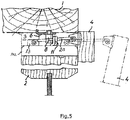
- a first embodiment of a locking assembly according to the invention is shown mounted in a ventilation window.
- the locking assembly is mounted in the ventilation window in a position conventional for the prior art locking assembly of Figs. 1 and 2 .
- Elements of the embodiment of figs. 5 and 6 similar to the prior art locking assembly of figs. 1 and 2 have been given similar reference numerals.
- An operator member 4 is located on the inside of the window in connection with a top sash member 2.
- an actuator slide 13 that protrudes through a slot 14 in the casing 102 of the locking assembly is moved towards the inside of the window (to the right in fig. 5 ), the operator member 4 and actuator slide 13 being connected via operator arm 20.
- pawls 11 that are connected to the actuator slide 13 via a system of link joint arms inside the casing 102 are being shifted from the positions shown in fig. 6 to positions at the other ends of slots 12 in the casing 102.
- the pawls 11 come into contact with abutment members 8 projecting from a strike plate 6 that is fixed to the top frame member 1 as shown in fig. 5 whereby they are pushed back into the positions shown in fig. 6 .
- the window may be opened slightly by placing the actuator slide 13 in an intermediate position.
- the casing 102 of the locking assembly of the invention is provided with upwards projecting shielding means 103 that renders access to the actuator slide 13 and other moveable parts of the locking assembly virtually impossible.
- the shielding means 103 are primarily meant to hinder access to the actuator slide 13 when in its locked position, closest to the outside of the window. It may be possible to gain access to the actuator slide 13 when in its intermediate ventilating position, but any tools that a potential intruder would use would have to be extremely slim, as it would have to fit in the very narrow space between the casing 102 and the strike plate 6.
- the shielding means 103 may cover that entire side of the casing 102 that runs parallel to the length axis of the sash member 2 and faces the outside of the window.
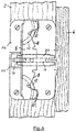
- the protection of the actuator slide 13 may also be achieved with a bridge-like structure 104 covering the actuator slide 13 at the outer end of the guiding slot 14, as shown in a second embodiment of the locking assembly according to the invention in fig. 7 , or covering the entire length of the slot.
- the bridge 104 will prevent intruders from using instruments that are wider than its internal width and if smaller tools are used it will take a considerable precision to reach the actuator slide 13.
- the bridge 104 may be formed by welding or screwing an extra piece of metal onto the casing or by punching or pressing, thus creating the guiding slot 14 by displacing material instead of cutting it away.
- the slot 14 can be made wider and provided with a plastic insert 101 so that the effective width of the slot is approximately the same as before.
- An example of this is shown in fig. 8 .
- the slot 14 has been extended to reach and penetrate the side 105 of the casing 102, which is substantially perpendicular to the surface of the sash member 2 on which it is mounted as may be seen in figs. 3 and 4 . This allows the insert 101 to be slid into place as illustrated with the arrow in fig. 8 .
- Both the cut-out 106 in the side of the casing and the insert has a dovetail shaped cross-section, which prevents the insert from coming loose during handling of the window in connection with the mounting thereof.
- the insert 101 may be provided with upstanding parts that may serve as shielding means.
- the abovementioned bridge structure 104 may be formed as an integral part of the plastic insert.
- the insert might, however, also be provided with flange-like projections along its entire length or the like.
- the shielding means could also be provided as separate elements that can be added to the insert as a click-on or in other suitable ways.
- the shielding means 103, 104 may also be formed as a combination of the embodiments described above.
- the bridge structure 104 formed on the plastic insert may be used together with the projecting metal part on the edge of the casing 102.
- the shielding means 103 may consist of one or more parts made from one or more materials. Disclosed embodiments include:
Description
- The present invention relates to a locking assembly for a ventilating window having a sash arranged to be openable with respect to a main frame by pivotal movement about an axis parallel to a pair of opposed sash members, said locking assembly comprising a strike plate fixed to a main frame member opposite one of said pair of sash members and a casing fixed to said one sash member opposite the strike plate, a locking mechanism arranged in said casing being operable by an operator member accessible from the inside of the window via at least one actuator slide displaceable in guide means in the casing between a first end position defining the unlocked position and a second end position defining the locked position.
- A locking assembly of the above-mentioned type is disclosed in
DK-C-114 046 - The above-described locking assembly works very well, but there is a risk that unauthorized access to the inside of the building may be obtained by introducing a flat, stiff object from the outside of the window into the slit between the sash and frame then pushing the actuator slide to its first, unlocked position.
- Means for preventing such unwarranted opening have been described in the international patent application
WO 99/51832 PA 2001 00601 -
WO 99/51832 - In the applicant's Danish patent application no.
PA 2001 00601 EP 0 969 178 A shows a known locking assembly with a shielding means fixed to the ventilation window frame. It is therefore the object of the present invention to provide a locking mechanism that has means for preventing intrusion, said means being effective primarily in the area around the actuator slide and working without a preceding activation. - The object is achieved with a locking assembly according to claim 1. The shielding means can be arranged between the actuator slide and the outside of the window. No extra parts have to be added to the locking assembly and the adding of the shielding means does therefore not complicate the mounting of the locking assembly. Inserts in the guide means may be used for the purpose of hindering noise and wear otherwise caused by metal-to-metal contact between the actuator slide and the casing. Adding the shielding means in this way does therefore not mean the adding of extra parts either and the abovementioned advantages of making the shielding means part of an existing part are retained.
- An improvement of the protection against intrusion can be reached by letting the shielding means consist of more than one part, preferably a part of the casing as well as a part of an insert in the guide means.
- In many cases it is advantageous that different parts of the shielding means consists of different materials. For instance soft material may be used where the use of a harder one would cause unwanted noise.
- The invention will now be described in detail with reference to the accompanying drawing, in which
-
fig. 1 is a perspective view of a prior art locking assembly; -
fig. 2 is a perspective view of the locking assembly offig. 1 seen from another angle; -
fig. 3 is a perspective view of the locking assembly offig. 1 mounted in a ventilating window and shown in a locked position of the window; -
fig. 4 is a perspective view corresponding to the view offig. 3 with the window in an unlocked position; -
fig. 5 is a sectional view of the upper part of a ventilating window incorporating an embodiment of the locking assembly of the invention; -
fig. 6 is a schematic plane view of the locking assembly shown infig. 5 ; -
fig. 7 is a schematic plane view of a second embodiment of the locking assembly of the invention; and -
fig. 8 is a sketch of the casing and an insert for use therewith. -
Figs. 1 and 2 show perspective views of a prior art locking assembly. Infigs. 3 and 4 the locking assembly is mounted in a ventilating window. As is best seen fromfigs. 1 and 2 , acasing 102 encases a locking mechanism and comprises fasteningholes 55 for mounting the locking assembly to a top sash member 2 (cf.figs. 3 and 4 ) of a window sash.Pawls 11 andactuator slide 13 extend through first andsecond slots pins 30 are used for fastening the locking mechanism in thecasing 102.Slots actuator slide 13 is preferably mounted with afriction plate 50 and anoperator arm 20 mounted with ahinge pin 25 to the part of theactuator slide 13 that extends through thecasing 102. Theoperator arm 20 is to be mounted to an operator member 4 (cf.figs. 3 and 4 ) by means of an operator hinge 10 with fastening holes. The locking mechanism shown infig. 2 comprisesfirst arms 60 withcutouts 65,second arms 62 connected in one piece to thepawls 11,first spring wires 64,second spring wires 66, theactuator slide 13 and first, second andthird arm hinges actuator slide 13 is moveable between three resting positions; a first, unlocked position in which the window is open or can be opened without activating the locking assembly (figs. 1, 2 and4 ), a second, locked position in which the window is locked in a closed position (not shown) and a third, intermediate position where the window is slightly open to achieve ventilation (fig. 3 ). - As may be seen from
fig. 2 , theactuator slide 13 and thepawls 11 are interconnected via the locking mechanism, which comprises a system of the second and the first spring-loadedarms second spring wires pawls 11 only move between a locked pawl position and an unlocked pawl position. Infigs. 1, 2 and4 thepawls 11 are shown in the unlocked pawl position. The locking mechanism operates symmetrically around theslot 14 and theactuator slide 13. Thefirst arms 60 of the locking mechanism are connected to theactuator slide 13 via thefirst arm hinge 70 and to thesecond arms 62 via thesecond arm hinge 72. Thesecond arms 62 of the locking mechanism are fastened to thecasing 102 via thethird arm hinge 74. Thefirst spring wires 64 are mounted to thecasing 102 via fasteningpin heads 31 and fastened to thesecond arm hinges 72, and thesecond spring wires 66 are mounted on thefirst arms 60 and fastened to thefirst arm hinge 70. - In the second, locked position the
actuator slide 13 and thepawls 11 are positioned at the other ends ofslots figs. 1 and 2 . Theactuator slide 13 is held in the first, unlocked position by thesecond spring wires 66 and a first dead point of the locking mechanism. Theactuator slide 13 is moved from the second, locked position to the third, intermediate position by moving theactuator slide 13 through said first dead point towards the opposite end of theslot 14. In the embodiment shown the first dead point is implemented as a combination of thesecond spring wires 66 mounted in thecutout 65 of thefirst arms 60 and the form of thefirst arms 60 and the first arm hinges 70. The position of thepawls 11 is not affected by moving theactuator slide 13 between the second, locked position and the third, intermediate position. - In the third, intermediate position the
actuator slide 13 is positioned between the ends ofslot 14 as may be seen infig. 3 , without having moved thesecond arms 62 of the locking mechanism. - The
actuator slide 13 is held in the third, intermediate position by the first dead point and a second dead point established by thefirst spring wires 66. In the second, locked position and third intermediate position of the actuator slide 13 thefirst spring wires 64 hold thepawls 11 in a locked position at the opposite ends of theslots 12 compared to the position of thepawls 11 infigs. 1 and 2 . - Moving the
actuator slide 13 from the third, intermediate position to the first, unlocked position, said second dead point is passed and thearms fig. 2 . In the first, unlocked position of the actuator slide 13 thefirst spring wires 64 hold thepawls 11 in the unlocked pawl position. The embodiment infig. 2 shows said second dead point implemented by thefirst spring wires 64 operating on thesecond arm hinges 72. Thepawls 11 are operating in conjunction with thesecond arm hinges 72 and are implemented as an integrated part of thesecond arms 62 of the operating mechanism. - As described above when the window is closed, the movement of the
pawls 11 is transmitted to theactuator slide 13 via the locking mechanism and theactuator slide 13 is pulled back from the first, unlocked position shown infig. 2 to the third, intermediate position. - In the third, intermediate position the
actuator slide 13 can be moved to the first, unlocked position as described above or moved to the second, locked position by passing the first dead point of the operating mechanism. - In
figs. 3 and 4 thecasing 102 of the locking hinge is shown in a mounted position secured to thesash member 2 by means ofscrews 55a inserted through fastening holes 55 and by the fastening pins 31 which extend from the casing (cf.fig. 2 ). Theoperator arm 20 is secured to theoperator member 4 of the window by means ofscrews 10a through fastening holes of theoperator hinge 10. Infig. 4 theactuator slide 13 is shown in the first, unlocked position in which the window is open or can be opened without activating the locking assembly; infig. 3 the actuator slide is shown in the third, intermediate position in which the window is locked but slightly open to achieve ventilation. - To reduce operating noise and ease operation of the locking assembly the locking mechanism may be lubricated.
- In
figs. 5 and6 a first embodiment of a locking assembly according to the invention is shown mounted in a ventilation window. The locking assembly is mounted in the ventilation window in a position conventional for the prior art locking assembly ofFigs. 1 and 2 . Elements of the embodiment offigs. 5 and6 similar to the prior art locking assembly offigs. 1 and 2 have been given similar reference numerals. Anoperator member 4 is located on the inside of the window in connection with atop sash member 2. When pulling on theoperator member 4 to open the window, anactuator slide 13 that protrudes through aslot 14 in thecasing 102 of the locking assembly is moved towards the inside of the window (to the right infig. 5 ), theoperator member 4 andactuator slide 13 being connected viaoperator arm 20. Simultaneously,pawls 11 that are connected to theactuator slide 13 via a system of link joint arms inside thecasing 102 are being shifted from the positions shown infig. 6 to positions at the other ends ofslots 12 in thecasing 102. When closing the window, thepawls 11 come into contact withabutment members 8 projecting from astrike plate 6 that is fixed to the top frame member 1 as shown infig. 5 whereby they are pushed back into the positions shown infig. 6 . To achieve ventilation with only a limited loss of heat the window may be opened slightly by placing theactuator slide 13 in an intermediate position. To prevent an intruder from opening the window from the outside, according to the invention thecasing 102 of the locking assembly of the invention is provided with upwards projecting shielding means 103 that renders access to theactuator slide 13 and other moveable parts of the locking assembly virtually impossible. In the embodiment offig. 6 the shielding means 103 are primarily meant to hinder access to theactuator slide 13 when in its locked position, closest to the outside of the window. It may be possible to gain access to theactuator slide 13 when in its intermediate ventilating position, but any tools that a potential intruder would use would have to be extremely slim, as it would have to fit in the very narrow space between thecasing 102 and thestrike plate 6. However, it may be preferable to extend the shielding means 103 along the sides of theslot 14 so that theactuator slide 13 is also covered when in its intermediate position. Alternatively, the shielding means 103 may cover that entire side of thecasing 102 that runs parallel to the length axis of thesash member 2 and faces the outside of the window. - The protection of the
actuator slide 13 may also be achieved with a bridge-like structure 104 covering theactuator slide 13 at the outer end of the guidingslot 14, as shown in a second embodiment of the locking assembly according to the invention infig. 7 , or covering the entire length of the slot. Thebridge 104 will prevent intruders from using instruments that are wider than its internal width and if smaller tools are used it will take a considerable precision to reach theactuator slide 13. Thebridge 104 may be formed by welding or screwing an extra piece of metal onto the casing or by punching or pressing, thus creating the guidingslot 14 by displacing material instead of cutting it away. - It has been found that metal-to-metal contact between the
actuator slide 13 and thecasing 102 may cause unwanted noise and a substantial wear on the locking assembly. To prevent these drawbacks theslot 14 can be made wider and provided with aplastic insert 101 so that the effective width of the slot is approximately the same as before. An example of this is shown infig. 8 . Here theslot 14 has been extended to reach and penetrate theside 105 of thecasing 102, which is substantially perpendicular to the surface of thesash member 2 on which it is mounted as may be seen infigs. 3 and 4 . This allows theinsert 101 to be slid into place as illustrated with the arrow infig. 8 . Both the cut-out 106 in the side of the casing and the insert has a dovetail shaped cross-section, which prevents the insert from coming loose during handling of the window in connection with the mounting thereof. Though depicted in a very simple form, theinsert 101 may be provided with upstanding parts that may serve as shielding means. As an example, theabovementioned bridge structure 104 may be formed as an integral part of the plastic insert. In other embodiments the insert might, however, also be provided with flange-like projections along its entire length or the like. The shielding means could also be provided as separate elements that can be added to the insert as a click-on or in other suitable ways. - The shielding means 103, 104 may also be formed as a combination of the embodiments described above. For instance the
bridge structure 104 formed on the plastic insert may be used together with the projecting metal part on the edge of thecasing 102. Thus, the shielding means 103 may consist of one or more parts made from one or more materials. Disclosed embodiments include: - 1. A locking assembly for a ventilating window having a sash arranged to be openable with respect to a main frame by pivotal movement about an axis parallel to a pair of opposed sash members, said locking assembly comprising a strike plate (6) fixed to a main frame member (1) opposite one of said pair of sash members (2) and a casing (102) fixed to said one sash member (2) opposite the strike plate (6), a locking mechanism arranged in said casing (102) being operable by an operator member (4) accessible from the inside of the window via at least one actuator slide (13) displaceable in guide means (14) in the casing between a first end position defining the unlocked position and a second end position defining the locking position, wherein shielding means (103) are fixed in relation to the casing (102) where at least a part of said shielding means (103) is arranged between the actuator slide (13) and the outside of the window.
- 2. A locking assembly for a window according to embodiment 1, wherein the shielding means (103) is an integral part of the casing (102).
- 3. A locking assembly for a window according to embodiment 1, wherein the shielding means (103) consist of one or more separate parts that are fastened to the casing (102) in a releasable manner.
- 4. A locking assembly for a window according to embodiment 1, wherein the shielding means (104) are part of an insert (101) in the guide means (14).
- 5. A locking assembly for a window according to embodiment 1, wherein the shielding means (103) consist of more than one part, preferably a part of the casing (102) as well as a part of an insert (101) in the guide means (14).
- 6. A locking assembly for a window according to
embodiment 4, wherein different parts of the shielding means (103) consists of different materials.
Claims (8)
- A locking assembly for a ventilating window having a sash arranged to be openable with respect to a main frame by pivotal movement about an axis parallel to a pair of opposed sash members, said locking assembly comprising a strike plate (6) fixed to a main frame member (1) opposite one of said pair of sash members (2) and a casing (102) fixed to said one sash member (2) opposite the strike plate (6), a locking mechanism arranged in said casing (102) being operable by an operator member (4) accessible from the inside of the window via at least one actuator slide (13) displaceable in guide means (14) in the casing between a first end position defining the unlocked position and a second end position defining the locking position, characterized in
that shielding means (103, 104) are fixed in relation to the casing (102) and include a bridge-like structure covering the actuator slide (13), and
that the shielding means (103, 104) include an integral part of the casing (102), or that the shielding means (103, 104) consist of one or more separate parts that are fastened to the casing (102) in a releasable manner and/or are part of an insert (101) in the guide means (14). - A locking assembly for a window according to claim 1, characterized in that bridge-like structure covers the entire length of the guide means (14).
- A locking assembly for a window according to claim 1 or 2, characterized in that at least a part of said shielding means (103, 104) is arranged between the actuator slide (13) and the outside of the window.
- A locking assembly for a window according to any of claims 1-3, characterized in that the bridge-like structure (104) is formed by an extra piece of metal, which has been welded or screwed onto the casing (102).
- A locking assembly for a window according to claim 1, characterized in that the bridge-like structure (104) is formed by material displaced by punching or pressing during creation of the guide means (14).
- A locking assembly for a window according to any of claims 1-5, characterized in that the shielding means (103, 104) consist of more than one part, preferably a part of the casing (102) as well as a part of an insert (101) in the guide means (14).
- A locking assembly for a window according to claim 6, characterized in that the bridge-like structure (104) is formed on a plastic insert in the guide means (14) and used together with a projecting metal part on the edge of the casing (102).
- A locking assembly for a window according to claim 6 or 7, characterized in that different parts of the shielding means (103, 104) consist of different materials.
Priority Applications (1)
| Application Number | Priority Date | Filing Date | Title |
|---|---|---|---|
| PL15165497T PL2944748T3 (en) | 2006-06-26 | 2007-06-26 | A locking assembly for a ventilating window |
Applications Claiming Priority (2)
| Application Number | Priority Date | Filing Date | Title |
|---|---|---|---|
| DKPA200600857 | 2006-06-26 | ||
| EP20070111047 EP1873336B1 (en) | 2006-06-26 | 2007-06-26 | A locking assembly for a ventilating window |
Related Parent Applications (1)
| Application Number | Title | Priority Date | Filing Date |
|---|---|---|---|
| EP20070111047 Division EP1873336B1 (en) | 2006-06-26 | 2007-06-26 | A locking assembly for a ventilating window |
Publications (2)
| Publication Number | Publication Date |
|---|---|
| EP2944748A1 EP2944748A1 (en) | 2015-11-18 |
| EP2944748B1 true EP2944748B1 (en) | 2017-11-01 |
Family
ID=38372360
Family Applications (2)
| Application Number | Title | Priority Date | Filing Date |
|---|---|---|---|
| EP20070111047 Not-in-force EP1873336B1 (en) | 2006-06-26 | 2007-06-26 | A locking assembly for a ventilating window |
| EP15165497.7A Not-in-force EP2944748B1 (en) | 2006-06-26 | 2007-06-26 | A locking assembly for a ventilating window |
Family Applications Before (1)
| Application Number | Title | Priority Date | Filing Date |
|---|---|---|---|
| EP20070111047 Not-in-force EP1873336B1 (en) | 2006-06-26 | 2007-06-26 | A locking assembly for a ventilating window |
Country Status (3)
| Country | Link |
|---|---|
| EP (2) | EP1873336B1 (en) |
| CN (1) | CN201056920Y (en) |
| PL (2) | PL2944748T3 (en) |
Families Citing this family (5)
| Publication number | Priority date | Publication date | Assignee | Title |
|---|---|---|---|---|
| EP3091150B1 (en) | 2009-06-29 | 2017-04-12 | VKR Holding A/S | A lock assembly |
| EP2499317B1 (en) * | 2009-11-11 | 2015-02-25 | VKR Holding A/S | Door or window brake device for a door or window assembly |
| CN102859101B (en) * | 2010-03-19 | 2014-12-17 | 宁波市鄞州松井工贸有限公司 | Locking device for windows and doors |
| EP3372763A1 (en) * | 2010-08-02 | 2018-09-12 | Zhijun Dong | Closure assembly equipped with ventilation and locking system |
| DK180431B1 (en) | 2018-09-24 | 2021-04-23 | Vkr Holding As | A roof window with an improved lock casing |
Family Cites Families (5)
| Publication number | Priority date | Publication date | Assignee | Title |
|---|---|---|---|---|
| DK114046C (en) * | 1968-03-26 | 1970-03-31 | Rasmussen V & Co Fa | Locking brackets for windows, in particular tilting and turning windows. |
| FR2767555B1 (en) * | 1997-08-22 | 1999-11-12 | Patrice Kandin | SECURITY DEVICE FOR PREVENTING THE OPENING OF THE EXTERIOR OF A ROOF WINDOW, WHILE MAINTAINING THE USE OF THE EXISTING VENTILATION SYSTEM OF THIS WINDOW |
| EP1070181B1 (en) * | 1998-04-07 | 2003-05-21 | VKR Holding A/S | A roof window with a ventilating frame top member |
| EP0969178A1 (en) * | 1998-06-30 | 2000-01-05 | VELUX Industri A/S | A window with a ventilation cover and a burglary preventing member |
| ES2339105T3 (en) * | 2001-04-11 | 2010-05-17 | Vkr Holding A/S | BLOCKING DEVICE FOR VENTILATION WINDOW. |
-
2007
- 2007-02-06 CN CNU2007200033689U patent/CN201056920Y/en not_active Expired - Fee Related
- 2007-06-26 PL PL15165497T patent/PL2944748T3/en unknown
- 2007-06-26 EP EP20070111047 patent/EP1873336B1/en not_active Not-in-force
- 2007-06-26 PL PL07111047T patent/PL1873336T3/en unknown
- 2007-06-26 EP EP15165497.7A patent/EP2944748B1/en not_active Not-in-force
Non-Patent Citations (1)
| Title |
|---|
| None * |
Also Published As
| Publication number | Publication date |
|---|---|
| EP2944748A1 (en) | 2015-11-18 |
| PL1873336T3 (en) | 2015-10-30 |
| CN201056920Y (en) | 2008-05-07 |
| PL2944748T3 (en) | 2018-03-30 |
| EP1873336B1 (en) | 2015-04-29 |
| EP1873336A1 (en) | 2008-01-02 |
Similar Documents
| Publication | Publication Date | Title |
|---|---|---|
| EP2944748B1 (en) | A locking assembly for a ventilating window | |
| US6185871B1 (en) | Door structure | |
| JP5183248B2 (en) | Sliding door sash | |
| JP6820436B2 (en) | Push rod locks for switch cabinet enclosures, corresponding devices, and corresponding methods | |
| JP2008161549A (en) | Laundry machine | |
| EP2447452A1 (en) | Catch for a lock, assembly of a catch and lock and/or a closing element and a method for closing a closing element | |
| CN113557345B (en) | Hinge lock | |
| US8403381B2 (en) | Horse stall door latch | |
| EP2937496B1 (en) | Operating handle for a folding/sliding door | |
| JP2021080643A (en) | Window opening and closing lock apparatus | |
| KR200405565Y1 (en) | The control unit to open windows | |
| US6068304A (en) | Espagnolette edge bar assembly | |
| LU101528B1 (en) | Ventilation device and window or door incorporating same | |
| JP4231223B2 (en) | Sliding door handle | |
| JP5349280B2 (en) | Sliding door locking device | |
| JP4074462B2 (en) | Window ventilation stay | |
| JPH08210046A (en) | Fitting | |
| WO2010036200A1 (en) | Lock device | |
| JP2005232803A (en) | Opening/closing cover | |
| EP2915945B1 (en) | A ventilation and operating assembly having a locking device | |
| JP4699912B2 (en) | Toilet booth door | |
| JP6522315B2 (en) | sash | |
| JP6713725B2 (en) | Window stay | |
| KR20150042955A (en) | Window System for Extended Balcony | |
| JP7221044B2 (en) | Fittings |
Legal Events
| Date | Code | Title | Description |
|---|---|---|---|
| PUAI | Public reference made under article 153(3) epc to a published international application that has entered the european phase |
Free format text: ORIGINAL CODE: 0009012 |
|
| AC | Divisional application: reference to earlier application |
Ref document number: 1873336 Country of ref document: EP Kind code of ref document: P |
|
| AK | Designated contracting states |
Kind code of ref document: A1 Designated state(s): AT BE BG CH CY CZ DE DK EE ES FI FR GB GR HU IE IS IT LI LT LU LV MC MT NL PL PT RO SE SI SK TR |
|
| 17P | Request for examination filed |
Effective date: 20160518 |
|
| RBV | Designated contracting states (corrected) |
Designated state(s): AT BE BG CH CY CZ DE DK EE ES FI FR GB GR HU IE IS IT LI LT LU LV MC MT NL PL PT RO SE SI SK TR |
|
| GRAP | Despatch of communication of intention to grant a patent |
Free format text: ORIGINAL CODE: EPIDOSNIGR1 |
|
| INTG | Intention to grant announced |
Effective date: 20170509 |
|
| GRAS | Grant fee paid |
Free format text: ORIGINAL CODE: EPIDOSNIGR3 |
|
| GRAA | (expected) grant |
Free format text: ORIGINAL CODE: 0009210 |
|
| AC | Divisional application: reference to earlier application |
Ref document number: 1873336 Country of ref document: EP Kind code of ref document: P |
|
| AK | Designated contracting states |
Kind code of ref document: B1 Designated state(s): AT BE BG CH CY CZ DE DK EE ES FI FR GB GR HU IE IS IT LI LT LU LV MC MT NL PL PT RO SE SI SK TR |
|
| REG | Reference to a national code |
Ref country code: GB Ref legal event code: FG4D |
|
| REG | Reference to a national code |
Ref country code: CH Ref legal event code: EP Ref country code: AT Ref legal event code: REF Ref document number: 942198 Country of ref document: AT Kind code of ref document: T Effective date: 20171115 |
|
| REG | Reference to a national code |
Ref country code: IE Ref legal event code: FG4D |
|
| REG | Reference to a national code |
Ref country code: DE Ref legal event code: R096 Ref document number: 602007052936 Country of ref document: DE |
|
| REG | Reference to a national code |
Ref country code: NL Ref legal event code: MP Effective date: 20171101 |
|
| REG | Reference to a national code |
Ref country code: LT Ref legal event code: MG4D |
|
| REG | Reference to a national code |
Ref country code: AT Ref legal event code: MK05 Ref document number: 942198 Country of ref document: AT Kind code of ref document: T Effective date: 20171101 |
|
| PG25 | Lapsed in a contracting state [announced via postgrant information from national office to epo] |
Ref country code: ES Free format text: LAPSE BECAUSE OF FAILURE TO SUBMIT A TRANSLATION OF THE DESCRIPTION OR TO PAY THE FEE WITHIN THE PRESCRIBED TIME-LIMIT Effective date: 20171101 Ref country code: SE Free format text: LAPSE BECAUSE OF FAILURE TO SUBMIT A TRANSLATION OF THE DESCRIPTION OR TO PAY THE FEE WITHIN THE PRESCRIBED TIME-LIMIT Effective date: 20171101 Ref country code: FI Free format text: LAPSE BECAUSE OF FAILURE TO SUBMIT A TRANSLATION OF THE DESCRIPTION OR TO PAY THE FEE WITHIN THE PRESCRIBED TIME-LIMIT Effective date: 20171101 Ref country code: NL Free format text: LAPSE BECAUSE OF FAILURE TO SUBMIT A TRANSLATION OF THE DESCRIPTION OR TO PAY THE FEE WITHIN THE PRESCRIBED TIME-LIMIT Effective date: 20171101 Ref country code: LT Free format text: LAPSE BECAUSE OF FAILURE TO SUBMIT A TRANSLATION OF THE DESCRIPTION OR TO PAY THE FEE WITHIN THE PRESCRIBED TIME-LIMIT Effective date: 20171101 |
|
| REG | Reference to a national code |
Ref country code: FR Ref legal event code: PLFP Year of fee payment: 12 |
|
| PG25 | Lapsed in a contracting state [announced via postgrant information from national office to epo] |
Ref country code: AT Free format text: LAPSE BECAUSE OF FAILURE TO SUBMIT A TRANSLATION OF THE DESCRIPTION OR TO PAY THE FEE WITHIN THE PRESCRIBED TIME-LIMIT Effective date: 20171101 Ref country code: IS Free format text: LAPSE BECAUSE OF FAILURE TO SUBMIT A TRANSLATION OF THE DESCRIPTION OR TO PAY THE FEE WITHIN THE PRESCRIBED TIME-LIMIT Effective date: 20180301 Ref country code: BG Free format text: LAPSE BECAUSE OF FAILURE TO SUBMIT A TRANSLATION OF THE DESCRIPTION OR TO PAY THE FEE WITHIN THE PRESCRIBED TIME-LIMIT Effective date: 20180201 Ref country code: LV Free format text: LAPSE BECAUSE OF FAILURE TO SUBMIT A TRANSLATION OF THE DESCRIPTION OR TO PAY THE FEE WITHIN THE PRESCRIBED TIME-LIMIT Effective date: 20171101 Ref country code: GR Free format text: LAPSE BECAUSE OF FAILURE TO SUBMIT A TRANSLATION OF THE DESCRIPTION OR TO PAY THE FEE WITHIN THE PRESCRIBED TIME-LIMIT Effective date: 20180202 |
|
| PG25 | Lapsed in a contracting state [announced via postgrant information from national office to epo] |
Ref country code: CZ Free format text: LAPSE BECAUSE OF FAILURE TO SUBMIT A TRANSLATION OF THE DESCRIPTION OR TO PAY THE FEE WITHIN THE PRESCRIBED TIME-LIMIT Effective date: 20171101 Ref country code: CY Free format text: LAPSE BECAUSE OF FAILURE TO SUBMIT A TRANSLATION OF THE DESCRIPTION OR TO PAY THE FEE WITHIN THE PRESCRIBED TIME-LIMIT Effective date: 20171101 Ref country code: EE Free format text: LAPSE BECAUSE OF FAILURE TO SUBMIT A TRANSLATION OF THE DESCRIPTION OR TO PAY THE FEE WITHIN THE PRESCRIBED TIME-LIMIT Effective date: 20171101 Ref country code: DK Free format text: LAPSE BECAUSE OF FAILURE TO SUBMIT A TRANSLATION OF THE DESCRIPTION OR TO PAY THE FEE WITHIN THE PRESCRIBED TIME-LIMIT Effective date: 20171101 Ref country code: SK Free format text: LAPSE BECAUSE OF FAILURE TO SUBMIT A TRANSLATION OF THE DESCRIPTION OR TO PAY THE FEE WITHIN THE PRESCRIBED TIME-LIMIT Effective date: 20171101 |
|
| REG | Reference to a national code |
Ref country code: DE Ref legal event code: R097 Ref document number: 602007052936 Country of ref document: DE |
|
| PG25 | Lapsed in a contracting state [announced via postgrant information from national office to epo] |
Ref country code: IT Free format text: LAPSE BECAUSE OF FAILURE TO SUBMIT A TRANSLATION OF THE DESCRIPTION OR TO PAY THE FEE WITHIN THE PRESCRIBED TIME-LIMIT Effective date: 20171101 Ref country code: RO Free format text: LAPSE BECAUSE OF FAILURE TO SUBMIT A TRANSLATION OF THE DESCRIPTION OR TO PAY THE FEE WITHIN THE PRESCRIBED TIME-LIMIT Effective date: 20171101 |
|
| PLBE | No opposition filed within time limit |
Free format text: ORIGINAL CODE: 0009261 |
|
| STAA | Information on the status of an ep patent application or granted ep patent |
Free format text: STATUS: NO OPPOSITION FILED WITHIN TIME LIMIT |
|
| 26N | No opposition filed |
Effective date: 20180802 |
|
| PG25 | Lapsed in a contracting state [announced via postgrant information from national office to epo] |
Ref country code: SI Free format text: LAPSE BECAUSE OF FAILURE TO SUBMIT A TRANSLATION OF THE DESCRIPTION OR TO PAY THE FEE WITHIN THE PRESCRIBED TIME-LIMIT Effective date: 20171101 |
|
| REG | Reference to a national code |
Ref country code: CH Ref legal event code: PL |
|
| REG | Reference to a national code |
Ref country code: BE Ref legal event code: MM Effective date: 20180630 |
|
| REG | Reference to a national code |
Ref country code: IE Ref legal event code: MM4A |
|
| PG25 | Lapsed in a contracting state [announced via postgrant information from national office to epo] |
Ref country code: LU Free format text: LAPSE BECAUSE OF NON-PAYMENT OF DUE FEES Effective date: 20180626 Ref country code: MC Free format text: LAPSE BECAUSE OF FAILURE TO SUBMIT A TRANSLATION OF THE DESCRIPTION OR TO PAY THE FEE WITHIN THE PRESCRIBED TIME-LIMIT Effective date: 20171101 |
|
| PG25 | Lapsed in a contracting state [announced via postgrant information from national office to epo] |
Ref country code: IE Free format text: LAPSE BECAUSE OF NON-PAYMENT OF DUE FEES Effective date: 20180626 Ref country code: LI Free format text: LAPSE BECAUSE OF NON-PAYMENT OF DUE FEES Effective date: 20180630 Ref country code: CH Free format text: LAPSE BECAUSE OF NON-PAYMENT OF DUE FEES Effective date: 20180630 |
|
| PG25 | Lapsed in a contracting state [announced via postgrant information from national office to epo] |
Ref country code: BE Free format text: LAPSE BECAUSE OF NON-PAYMENT OF DUE FEES Effective date: 20180630 |
|
| PGFP | Annual fee paid to national office [announced via postgrant information from national office to epo] |
Ref country code: AT Payment date: 20190522 Year of fee payment: 16 |
|
| PGFP | Annual fee paid to national office [announced via postgrant information from national office to epo] |
Ref country code: FR Payment date: 20190524 Year of fee payment: 13 |
|
| PG25 | Lapsed in a contracting state [announced via postgrant information from national office to epo] |
Ref country code: MT Free format text: LAPSE BECAUSE OF NON-PAYMENT OF DUE FEES Effective date: 20180626 |
|
| PG25 | Lapsed in a contracting state [announced via postgrant information from national office to epo] |
Ref country code: TR Free format text: LAPSE BECAUSE OF FAILURE TO SUBMIT A TRANSLATION OF THE DESCRIPTION OR TO PAY THE FEE WITHIN THE PRESCRIBED TIME-LIMIT Effective date: 20171101 |
|
| PG25 | Lapsed in a contracting state [announced via postgrant information from national office to epo] |
Ref country code: PT Free format text: LAPSE BECAUSE OF FAILURE TO SUBMIT A TRANSLATION OF THE DESCRIPTION OR TO PAY THE FEE WITHIN THE PRESCRIBED TIME-LIMIT Effective date: 20171101 |
|
| PG25 | Lapsed in a contracting state [announced via postgrant information from national office to epo] |
Ref country code: HU Free format text: LAPSE BECAUSE OF FAILURE TO SUBMIT A TRANSLATION OF THE DESCRIPTION OR TO PAY THE FEE WITHIN THE PRESCRIBED TIME-LIMIT; INVALID AB INITIO Effective date: 20070626 |
|
| PG25 | Lapsed in a contracting state [announced via postgrant information from national office to epo] |
Ref country code: FR Free format text: LAPSE BECAUSE OF NON-PAYMENT OF DUE FEES Effective date: 20200630 |
|
| PGFP | Annual fee paid to national office [announced via postgrant information from national office to epo] |
Ref country code: GB Payment date: 20220506 Year of fee payment: 16 Ref country code: DE Payment date: 20220505 Year of fee payment: 16 |
|
| PG25 | Lapsed in a contracting state [announced via postgrant information from national office to epo] |
Ref country code: PL Free format text: LAPSE BECAUSE OF NON-PAYMENT OF DUE FEES Effective date: 20200626 |
|
| REG | Reference to a national code |
Ref country code: DE Ref legal event code: R119 Ref document number: 602007052936 Country of ref document: DE |
|
| GBPC | Gb: european patent ceased through non-payment of renewal fee |
Effective date: 20230626 |