EP2944488B1 - Hlk-system mit zwei temperaturen - Google Patents
Hlk-system mit zwei temperaturen Download PDFInfo
- Publication number
- EP2944488B1 EP2944488B1 EP15166399.4A EP15166399A EP2944488B1 EP 2944488 B1 EP2944488 B1 EP 2944488B1 EP 15166399 A EP15166399 A EP 15166399A EP 2944488 B1 EP2944488 B1 EP 2944488B1
- Authority
- EP
- European Patent Office
- Prior art keywords
- air
- evaporator
- temperature
- section
- diffuser
- Prior art date
- Legal status (The legal status is an assumption and is not a legal conclusion. Google has not performed a legal analysis and makes no representation as to the accuracy of the status listed.)
- Not-in-force
Links
Images
Classifications
-
- B—PERFORMING OPERATIONS; TRANSPORTING
- B60—VEHICLES IN GENERAL
- B60H—ARRANGEMENTS OF HEATING, COOLING, VENTILATING OR OTHER AIR-TREATING DEVICES SPECIALLY ADAPTED FOR PASSENGER OR GOODS SPACES OF VEHICLES
- B60H1/00—Heating, cooling or ventilating devices
- B60H1/32—Cooling devices
- B60H1/3202—Cooling devices using evaporation, i.e. not including a compressor, e.g. involving fuel or water evaporation
-
- B—PERFORMING OPERATIONS; TRANSPORTING
- B60—VEHICLES IN GENERAL
- B60H—ARRANGEMENTS OF HEATING, COOLING, VENTILATING OR OTHER AIR-TREATING DEVICES SPECIALLY ADAPTED FOR PASSENGER OR GOODS SPACES OF VEHICLES
- B60H1/00—Heating, cooling or ventilating devices
- B60H1/00007—Combined heating, ventilating, or cooling devices
- B60H1/00021—Air flow details of HVAC devices
- B60H1/00064—Air flow details of HVAC devices for sending air streams of different temperatures into the passenger compartment
- B60H1/00071—Air flow details of HVAC devices for sending air streams of different temperatures into the passenger compartment the air passing only one heat exchanger
-
- B—PERFORMING OPERATIONS; TRANSPORTING
- B60—VEHICLES IN GENERAL
- B60H—ARRANGEMENTS OF HEATING, COOLING, VENTILATING OR OTHER AIR-TREATING DEVICES SPECIALLY ADAPTED FOR PASSENGER OR GOODS SPACES OF VEHICLES
- B60H1/00—Heating, cooling or ventilating devices
- B60H1/00007—Combined heating, ventilating, or cooling devices
- B60H1/00021—Air flow details of HVAC devices
- B60H2001/00114—Heating or cooling details
- B60H2001/00135—Deviding walls for separate air flows
-
- B—PERFORMING OPERATIONS; TRANSPORTING
- B60—VEHICLES IN GENERAL
- B60H—ARRANGEMENTS OF HEATING, COOLING, VENTILATING OR OTHER AIR-TREATING DEVICES SPECIALLY ADAPTED FOR PASSENGER OR GOODS SPACES OF VEHICLES
- B60H1/00—Heating, cooling or ventilating devices
- B60H1/00007—Combined heating, ventilating, or cooling devices
- B60H1/00021—Air flow details of HVAC devices
- B60H2001/0015—Temperature regulation
- B60H2001/00164—Temperature regulation with more than one by-pass
Definitions
- HVAC heating, ventilation, and air conditioning
- HVAC heating, ventilation, and air conditioning
- HVAC vehicle heating, ventilation, and air conditioning
- a comfortable temperature for spot cooling air is, for example, 24°C.
- air discharged by the system for general or volume cooling of the vehicle cabin is preferably much colder, 6°C to 15°C for example.
- spot cooling makes occupant comfort is less reliant on the average temperature of the cabin, the total amount of air discharged for cooling of the volume of cabin can be reduced. That is, spot cooling can be used to maintain occupant comfort in spite of the occupant residing in a higher than normal cabin temperature, 28°C - 32°C for example instead of a more typical cabin temperature of 24°C.
- HVAC heating, ventilation, and air conditioning
- the system includes an evaporator and a diffuser.
- the evaporator is configured to cool air passing through the evaporator.
- the diffuser is configured to direct a first portion of the air entering the diffuser through a first section of the evaporator, and direct a second portion of the air entering the diffuser through a second section of the evaporator.
- the evaporator and the diffuser are configured to cooperate such that air exits the first section at a first temperature and air exits the second section at a second temperature less than the first temperature.
- the diffuser is configured to direct the first portion through the first section at a first velocity, and direct the second portion through the second section at a second velocity less than the first velocity.
- system includes a partition configured to segregate the first portion of air from the second portion of air.
- the system includes an upstream valve operable to vary the first velocity.
- the system includes an upstream valve operable to vary the first velocity relative to the second velocity.
- the system includes a downstream valve operable to vary a mixture ratio of air at the second temperature with air at the first temperature.
- the first section of the evaporator is directed to spot cool an occupant residing in a cabin of the vehicle, and air from the second section of the evaporator is directed to volume cool the cabin of the vehicle.
- the system includes a nozzle configured to direct the air from the first section of the evaporator toward the occupant of the vehicle.
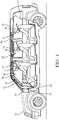
- Fig. 1 illustrates a non-limiting example of a heating, ventilation, and air conditioning (HVAC) system, hereafter the system 10, configured for use in a vehicle 12 to provide a perceived comfortable thermal environment to an occupant 14 seated in a cabin 18 of the vehicle 12.
- HVAC heating, ventilation, and air conditioning
- the system 10 described herein may also be adapted to be used in other types of vehicles, such as sedans, trucks, busses, or airplanes.
- the system 10 is configured to provide spot cooling to the occupants 14.
- spot cooling means directing a stream of air at a preferred temperature and flow rate toward a thermally sensitive portion of the occupant's body to provide a heat loss rate for the sensitive portion so the occupant perceives that the cabin 18 is at a comfortable temperature, 24°C for example, while the average cabin ambient temperature is actually higher, 30°C for example.
- the thermal comfort of an occupant 14 in a vehicle cabin 18 may be estimated based on a heat loss rate of the occupant 14.
- the occupant 14 may typically be comfortable in an ambient temperature of 24°C. If the heat loss rate of the occupant 14 is higher than when the ambient temperature is 24°C, the occupant 14 tends to feel cooler. If the heat loss rate of the occupant 14 is lower than when in an environment with an ambient temperature of 24°C, the occupant 14 tends to feel warmer.
- the system described herein provides spot cooling to maintain the heat loss rate of the occupant 14 in the cabin 18 at a rate that is similar to a cabin temperature of 24°C, while allowing a higher cabin temperature, for example 30°C.
- spot cooling is presented in Thermal
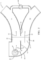
- Fig. 2 further illustrates non-limiting features of the system 10 which generally includes a diffuser 28 equipped with a single evaporator, hereafter the evaporator 24.
- the diffuser/evaporator assembly is typically disposed in a forward region of the vehicle 12.
- the evaporator 24 is generally configured to cool the air 16 passing through the evaporator 24. Movement of the air 16 may be by way of a fan 22, various suitable configurations of which will be recognized by those in the art.
- the air 16 may be drawing from outside of the vehicle 12, or from within the cabin 18, or a mixture of the two as will be recognized by those in the art. While the teachings presented herein are generally directed toward cooling, the teachings are generally applicable toward heating. That is, the comfort provided to the occupant 14 by spot cooling when the temperature outside the vehicle is high can also be provide by spot heating when the temperature outside the vehicle is low.
- the diffuser 28 is configured to direct a first portion 30 of the air 16 entering the diffuser 28 toward or through a first section 36 of the evaporator 24, and direct a second portion 32 of the air 16 entering the diffuser 28 toward or through a second section 38 of the evaporator 24.
- the first portion is characterized as between thirty percent (30%) and fifty percent (50%) of the air entering the diffuser.
- the evaporator 24 and the diffuser 28 are configured so the first portion 30 flows through the evaporator 24 at a greater velocity than the second portion 32.
- the evaporator 24 and the diffuser 28 cooperate so air exits the first section 36 at a first temperature T1 and air exits the second section 38 at a second temperature T2 less than the first temperature T 1.
- the first temperature is greater than ten degrees Celsius (10°C), preferably in the range of twelve degrees Celsius (12°C) to twenty-four degrees Celsius (24°C), and the second temperature is between four degrees Celsius (4°C) and twelve degrees Celsius (12°C).
- Controlling or managing the air 16 that flows through the evaporator 24 may be done by way of a 'virtual partition' that arises from the shape of the diffuser proximate to the evaporator 24.
- a 'virtual partition' that arises from the shape of the diffuser proximate to the evaporator 24.
- the walls of the diffuser 28 are relatively close (e.g. - less than 20mm) to inlet face of the evaporator proximate to the second section 38 of the evaporator, and are relatively far away (e.g. - more than 40mm) from the inlet face of the evaporator 24 proximate to the first section 36, then the relative velocities of the first portion 30 and the second portion 32 can be varied to achieve a desired relative difference between the first temperature T1 and the second temperature T2.
- the system 10 may include a duct 40 configured to guide the first portion 30 of the air 16 through one or more nozzles 42 towards temperature sensitive areas of the occupants 14 such as, but not limited to, the face, back of neck, or chest, as illustrated.
- the second portion 32 of the air 16 may be directed toward the floor of the cabin 18, or through openings in the dashboard area, or other areas by means recognized by those in the art for general cabin cooling and maintain comfortable cabin humidity, as opposed to being directed for spot cooling use.
- the system 10 may include a partition 44 configured to segregate the first portion 30 of air from the second portion 32 of air. While the partition 44 is shown as a fixed feature, it is contemplated that the partition could be movable so as to vary the effective size of the first section 36 relative to the second section 38 in response to number of occupants in the vehicle for achieving energy efficiency. Such variable control may be useful to control the value of the first temperature T1 or the second temperature T2, or the relative difference between the two temperatures. Having control over the temperatures may be advantageous during, for example, startup times after the vehicle 12 has been parked and the cabin temperature is uncomfortably high.
- the system 10 may include an upstream valve 46 located on or proximate to the inlet side of the evaporator 24.
- the upstream valve 46 operable to vary the first velocity of the first portion 30 or vary the first velocity of the first portion 30 relative to the second velocity of the second portion 32.
- the upstream valve 46 may be employed in conjunction with a fixed version of the partition 44, or a variable version of the partition 44 describe above in order to provide further flexibility to control the first temperature T1 and the second temperature T2.
- Such flexible control may be particularly advantageous to prevent freezing of the evaporator during high humidity conditions, or to maximize the cool down rate of the cabin 18 when recovering from a hot soak.
- the system 10 may include a downstream valve 48 operable to vary a mixture ratio of air at the second temperature T2 with air at the first temperature T2.
- the downstream valve 48 may be used in conjunction with or instead of the partition 44 and/or the upstream valve 46 to provide further flexibility with regard to controlling the temperatures and velocities of air flowing into the cabin 18. It is intended that during transient cooling of a heat soaked cabin, the HVAC system adapts to maximize the strength of the spot cooling stream while compromising the strength of the cabin conditioning stream during the initial cool down phase.
- the objective behind this micro cooling strategy as described earlier is to achieve quicker time to occupant comfort, while the cabin cools down at a slower rate relative to the occupants.
- HVAC heating, ventilation, and air conditioning
- the system 10 decreases the cost of a spot-cooling type system by utilizing a single shared evaporator (the evaporator 24) in combination with a diffuser equipped with various features capable to control the velocity of air passing through distinct sections of the evaporator 24.
- System efficiency is generally improved as the system can output two different temperatures of air with minimal reliance on reheating of already cooled air, while still maintaining excellent occupant comfort.
- the system 10 described herein stands in contrast to other systems that employ multiple evaporators to provide various temperatures of conditioned air to different locations in a vehicle
Landscapes
- Physics & Mathematics (AREA)
- Thermal Sciences (AREA)
- Engineering & Computer Science (AREA)
- Mechanical Engineering (AREA)
- Air-Conditioning For Vehicles (AREA)
Claims (10)
- System (10) zur Heizung, Belüftung und Klimatisierung (HVAC) für ein Fahrzeug (12), wobei das System (10) Folgendes umfasst:einen Verdampfer (24), der konfiguriert ist, Luft (16), die durch den Verdampfer (24) hindurchgeht, zu kühlen; undeinen Diffusor (28), der konfiguriert ist, eine erste Menge (30) der Luft (16), die in den Diffusor (28) eintritt, durch einen ersten Abschnitt (36) des Verdampfers (24) zu leiten und eine zweite Menge (32) der Luft (16), die in den Diffusor (28) eintritt, durch einen zweiten Abschnitt (38) des Verdampfers (24) zu leiten, dadurch gekennzeichnet, dass der Verdampfer(24) und der Diffusor (28) konfiguriert sind, derart zusammenzuwirken, dass Luft (16) den ersten Abschnitt (36) mit einer ersten Temperatur verlässt und Luft (16) den zweiten Abschnitt (38) mit einer zweiten Temperatur verlässt, die niedriger als die erste Temperatur ist.
- System nach Anspruch 1, wobei der Diffusor (28) konfiguriert ist, die erste Menge (30) mit einer ersten Geschwindigkeit durch den ersten Abschnitt (36) z leiten und die zweite Menge (32) mit einer zweiten Geschwindigkeit, die geringer als die erste Geschwindigkeit ist, durch den zweiten Abschnitt (38) zu leiten.
- System nach Anspruch 1 oder 2, wobei das System (10) eine Trennwand (44) umfasst, die konfiguriert ist, die erste Menge (30) von Luft (16) von der zweiten Menge (32) von Luft (16) zu trennen.
- System nach Anspruch 2 oder 3, wobei das System (10) ein stromaufwärts gelegenes Ventil (46) umfasst, das betriebsfähig ist, die erste Geschwindigkeit zu verändern.
- System nach einem der Ansprüche 2 oder 4, wobei das System (10) ein stromaufwärts gelegenes Ventil (46) umfasst, das betriebsfähig ist, die erste Geschwindigkeit relativ zu der zweiten Geschwindigkeit zu verändern.
- System nach einem der Ansprüche 1 bis 5, wobei das System (10) ein stromabwärts gelegenes Ventil (48) umfasst, das betriebsfähig ist, ein Mischungsverhältnis von Luft (16) mit der zweiten Temperatur und Luft (16) mit der ersten Temperatur zu verändern.
- System nach einem der Ansprüche 1 bis 6, wobei Luft (16) von dem ersten Abschnitt (36) des Verdampfers (24) gelenkt wird, um einen Insassen (14), der sich in einer Kabine (18) des Fahrzeugs (12) aufhält, gezielt zu kühlen, und Luft (16) von dem zweiten Abschnitt (38) des Verdampfers gelenkt wird, um den Raum der Kabine (18) des Fahrzeugs (12) zu kühlen.
- System nach Anspruch 7, wobei das System (10) eine Düse (42) umfasst, die konfiguriert ist, die Luft (16) von dem ersten Abschnitt (36) des Verdampfers (24) in Richtung des Insassen (14) des Fahrzeugs (12) zu leiten.
- System nach einem der Ansprüche 1 bis 8, wobei die erste Temperatur zwischen zehn Grad Celsius (10 °C) und vierundzwanzig Grad Celsius (24 °C) ist und die zweite Temperatur zwischen fünf Grad Celsius (5 °C) und zwanzig Grad Celsius (12 °C) ist.
- System nach einem der Ansprüche 1 bis 9, wobei der erste Menge (30) als zwischen dreißig Prozent (30 %) und fünfzig Prozent (50 %) der Luft (16), die in den Diffusor (28) eintritt, gekennzeichnet ist.
Applications Claiming Priority (1)
| Application Number | Priority Date | Filing Date | Title |
|---|---|---|---|
| US14/277,121 US9676253B2 (en) | 2014-05-14 | 2014-05-14 | Dual temperature HVAC system |
Publications (2)
| Publication Number | Publication Date |
|---|---|
| EP2944488A1 EP2944488A1 (de) | 2015-11-18 |
| EP2944488B1 true EP2944488B1 (de) | 2017-03-29 |
Family
ID=53039804
Family Applications (1)
| Application Number | Title | Priority Date | Filing Date |
|---|---|---|---|
| EP15166399.4A Not-in-force EP2944488B1 (de) | 2014-05-14 | 2015-05-05 | Hlk-system mit zwei temperaturen |
Country Status (4)
| Country | Link |
|---|---|
| US (1) | US9676253B2 (de) |
| EP (1) | EP2944488B1 (de) |
| KR (1) | KR20150130921A (de) |
| CN (1) | CN105082932B (de) |
Families Citing this family (1)
| Publication number | Priority date | Publication date | Assignee | Title |
|---|---|---|---|---|
| CN110525524B (zh) * | 2019-09-10 | 2020-07-31 | 郑州铁路职业技术学院 | 一种物流运输用变温车厢 |
Family Cites Families (15)
| Publication number | Priority date | Publication date | Assignee | Title |
|---|---|---|---|---|
| JPS6133313A (ja) | 1984-07-25 | 1986-02-17 | Diesel Kiki Co Ltd | 自動車用空気調和装置 |
| FR2631896B1 (fr) * | 1988-05-27 | 1990-08-24 | Valeo | Boitier de distribution pour dispositif de chauffage et/ou de climatisation, notamment pour vehicule automobile |
| US4949779A (en) | 1990-02-01 | 1990-08-21 | Eaton Corporation | Regulating heater discharge air temperature for front and rear passengers in a vehicle |
| US5309731A (en) | 1991-12-27 | 1994-05-10 | Nippondenso Co., Ltd. | Air conditioning apparatus |
| US5282367A (en) | 1992-04-24 | 1994-02-01 | The Delfield Company | Refrigerated food preparation table and method |
| SE9504564L (sv) * | 1995-12-20 | 1997-01-20 | Saab Automobile | Klimatanläggning och förfarande för reglering av klimatanläggning |
| JP3804152B2 (ja) * | 1997-02-20 | 2006-08-02 | 株式会社デンソー | 車両用空調装置 |
| US6192698B1 (en) * | 1998-03-12 | 2001-02-27 | Denso Corporation | Vehicle-air-conditioning system with cooling degree estimator for left/right temperature control |
| FR2787392B1 (fr) * | 1998-12-21 | 2002-01-11 | Valeo Climatisation | Dispositif de chauffage-climatisaiton d'encombrement reduit pour vehicule automobile |
| KR100601835B1 (ko) * | 1999-12-30 | 2006-07-19 | 한라공조주식회사 | 자동차용 공기조화장치 |
| US9248719B2 (en) * | 2008-08-20 | 2016-02-02 | Halla Visteon Climate Control Corporation | Dual zone type air conditioner for vehicles and method of controlling the same |
| US10029536B2 (en) * | 2009-05-29 | 2018-07-24 | Honda Motor Co., Ltd. | Integrated front and rear HVAC system |
| US8267757B2 (en) | 2009-07-10 | 2012-09-18 | Keihin Corporation | Vehicular air conditioning apparatus |
| US20110005732A1 (en) | 2009-07-10 | 2011-01-13 | Keihin Corporation | Vehicular air conditioning apparatus |
| US20120168117A1 (en) * | 2011-01-04 | 2012-07-05 | Automotive Components Holdings, Llc | Automotive HVAC Diffuser With Cooperating Wall Guide And Vane |
-
2014
- 2014-05-14 US US14/277,121 patent/US9676253B2/en not_active Expired - Fee Related
-
2015
- 2015-05-05 EP EP15166399.4A patent/EP2944488B1/de not_active Not-in-force
- 2015-05-11 KR KR1020150065129A patent/KR20150130921A/ko not_active Withdrawn
- 2015-05-13 CN CN201510243095.4A patent/CN105082932B/zh not_active Expired - Fee Related
Non-Patent Citations (1)
| Title |
|---|
| None * |
Also Published As
| Publication number | Publication date |
|---|---|
| CN105082932A (zh) | 2015-11-25 |
| CN105082932B (zh) | 2019-07-30 |
| US9676253B2 (en) | 2017-06-13 |
| KR20150130921A (ko) | 2015-11-24 |
| EP2944488A1 (de) | 2015-11-18 |
| US20150328956A1 (en) | 2015-11-19 |
Similar Documents
| Publication | Publication Date | Title |
|---|---|---|
| EP2719560B1 (de) | Heiz- und Kühlsystem für Insassen im hinteren Teil eines Fahrzeugs | |
| EP2517907B1 (de) | System und Verfahren zur Bereitstellung von schnellem Wärmekomfort mit verringerter Energie mithilfe der Klimatisierung ausgerichteter Punkte | |
| US20210276463A1 (en) | Vehicle zonal microclimate system | |
| US8187063B2 (en) | Evaporator frost prevention control logic for front and rear integrated HVAC system | |
| US11254187B2 (en) | Vehicular air conditioner | |
| US9682608B2 (en) | Supplemental heating and cooling sources for a heating, ventilation and air conditioning system | |
| KR20170041296A (ko) | 통합 독립공조 시스템 및 그 제어방법 | |
| US9956843B2 (en) | Climate control system | |
| CN107089111B (zh) | 机动车辆的空气调节系统 | |
| US9587850B2 (en) | HVAC temperature stratification improvement technique | |
| JP4821034B2 (ja) | 車両用エアコンディショニングユニット | |
| US11046147B2 (en) | Cabin condenser integrated temperature control system | |
| US9676253B2 (en) | Dual temperature HVAC system | |
| KR20170032871A (ko) | 역류 방지 제어부를 갖춘 hvac 모듈 및 운용 방법 | |
| JP6032353B2 (ja) | 空調システムのための専用床抽気 | |
| US20170274731A1 (en) | Hvac blower adjustable divergence | |
| US20140283543A1 (en) | Vehicle hvac system with lower mounted blower unit | |
| US20200189351A1 (en) | Vehicle hvac system | |
| JP6235271B2 (ja) | 車両用空調ユニット | |
| KR100923112B1 (ko) | 냉난방 시스템 | |
| JP2009160979A (ja) | 車両用空気調和装置 | |
| US20200384828A1 (en) | Outlet focused warm air channel | |
| KR102104529B1 (ko) | 차량용 공조 시스템 | |
| JP2008049984A (ja) | 車両用空調装置 | |
| US20200094652A1 (en) | HVAC Temperature Control System |
Legal Events
| Date | Code | Title | Description |
|---|---|---|---|
| PUAI | Public reference made under article 153(3) epc to a published international application that has entered the european phase |
Free format text: ORIGINAL CODE: 0009012 |
|
| AK | Designated contracting states |
Kind code of ref document: A1 Designated state(s): AL AT BE BG CH CY CZ DE DK EE ES FI FR GB GR HR HU IE IS IT LI LT LU LV MC MK MT NL NO PL PT RO RS SE SI SK SM TR |
|
| AX | Request for extension of the european patent |
Extension state: BA ME |
|
| 17P | Request for examination filed |
Effective date: 20160318 |
|
| RBV | Designated contracting states (corrected) |
Designated state(s): AL AT BE BG CH CY CZ DE DK EE ES FI FR GB GR HR HU IE IS IT LI LT LU LV MC MK MT NL NO PL PT RO RS SE SI SK SM TR |
|
| GRAP | Despatch of communication of intention to grant a patent |
Free format text: ORIGINAL CODE: EPIDOSNIGR1 |
|
| RIC1 | Information provided on ipc code assigned before grant |
Ipc: B60H 1/00 20060101AFI20160926BHEP Ipc: B60H 1/32 20060101ALI20160926BHEP |
|
| INTG | Intention to grant announced |
Effective date: 20161021 |
|
| GRAS | Grant fee paid |
Free format text: ORIGINAL CODE: EPIDOSNIGR3 |
|
| GRAA | (expected) grant |
Free format text: ORIGINAL CODE: 0009210 |
|
| AK | Designated contracting states |
Kind code of ref document: B1 Designated state(s): AL AT BE BG CH CY CZ DE DK EE ES FI FR GB GR HR HU IE IS IT LI LT LU LV MC MK MT NL NO PL PT RO RS SE SI SK SM TR |
|
| REG | Reference to a national code |
Ref country code: GB Ref legal event code: FG4D |
|
| REG | Reference to a national code |
Ref country code: CH Ref legal event code: EP |
|
| REG | Reference to a national code |
Ref country code: AT Ref legal event code: REF Ref document number: 879386 Country of ref document: AT Kind code of ref document: T Effective date: 20170415 |
|
| REG | Reference to a national code |
Ref country code: IE Ref legal event code: FG4D |
|
| REG | Reference to a national code |
Ref country code: DE Ref legal event code: R096 Ref document number: 602015001976 Country of ref document: DE |
|
| REG | Reference to a national code |
Ref country code: FR Ref legal event code: PLFP Year of fee payment: 3 |
|
| PG25 | Lapsed in a contracting state [announced via postgrant information from national office to epo] |
Ref country code: HR Free format text: LAPSE BECAUSE OF FAILURE TO SUBMIT A TRANSLATION OF THE DESCRIPTION OR TO PAY THE FEE WITHIN THE PRESCRIBED TIME-LIMIT Effective date: 20170329 Ref country code: LT Free format text: LAPSE BECAUSE OF FAILURE TO SUBMIT A TRANSLATION OF THE DESCRIPTION OR TO PAY THE FEE WITHIN THE PRESCRIBED TIME-LIMIT Effective date: 20170329 Ref country code: FI Free format text: LAPSE BECAUSE OF FAILURE TO SUBMIT A TRANSLATION OF THE DESCRIPTION OR TO PAY THE FEE WITHIN THE PRESCRIBED TIME-LIMIT Effective date: 20170329 Ref country code: NO Free format text: LAPSE BECAUSE OF FAILURE TO SUBMIT A TRANSLATION OF THE DESCRIPTION OR TO PAY THE FEE WITHIN THE PRESCRIBED TIME-LIMIT Effective date: 20170629 Ref country code: GR Free format text: LAPSE BECAUSE OF FAILURE TO SUBMIT A TRANSLATION OF THE DESCRIPTION OR TO PAY THE FEE WITHIN THE PRESCRIBED TIME-LIMIT Effective date: 20170630 |
|
| REG | Reference to a national code |
Ref country code: NL Ref legal event code: MP Effective date: 20170329 |
|
| REG | Reference to a national code |
Ref country code: AT Ref legal event code: MK05 Ref document number: 879386 Country of ref document: AT Kind code of ref document: T Effective date: 20170329 |
|
| PG25 | Lapsed in a contracting state [announced via postgrant information from national office to epo] |
Ref country code: RS Free format text: LAPSE BECAUSE OF FAILURE TO SUBMIT A TRANSLATION OF THE DESCRIPTION OR TO PAY THE FEE WITHIN THE PRESCRIBED TIME-LIMIT Effective date: 20170329 Ref country code: LU Free format text: LAPSE BECAUSE OF NON-PAYMENT OF DUE FEES Effective date: 20170531 Ref country code: LV Free format text: LAPSE BECAUSE OF FAILURE TO SUBMIT A TRANSLATION OF THE DESCRIPTION OR TO PAY THE FEE WITHIN THE PRESCRIBED TIME-LIMIT Effective date: 20170329 Ref country code: SE Free format text: LAPSE BECAUSE OF FAILURE TO SUBMIT A TRANSLATION OF THE DESCRIPTION OR TO PAY THE FEE WITHIN THE PRESCRIBED TIME-LIMIT Effective date: 20170329 Ref country code: BG Free format text: LAPSE BECAUSE OF FAILURE TO SUBMIT A TRANSLATION OF THE DESCRIPTION OR TO PAY THE FEE WITHIN THE PRESCRIBED TIME-LIMIT Effective date: 20170629 |
|
| PG25 | Lapsed in a contracting state [announced via postgrant information from national office to epo] |
Ref country code: NL Free format text: LAPSE BECAUSE OF FAILURE TO SUBMIT A TRANSLATION OF THE DESCRIPTION OR TO PAY THE FEE WITHIN THE PRESCRIBED TIME-LIMIT Effective date: 20170329 |
|
| PG25 | Lapsed in a contracting state [announced via postgrant information from national office to epo] |
Ref country code: SK Free format text: LAPSE BECAUSE OF FAILURE TO SUBMIT A TRANSLATION OF THE DESCRIPTION OR TO PAY THE FEE WITHIN THE PRESCRIBED TIME-LIMIT Effective date: 20170329 Ref country code: ES Free format text: LAPSE BECAUSE OF FAILURE TO SUBMIT A TRANSLATION OF THE DESCRIPTION OR TO PAY THE FEE WITHIN THE PRESCRIBED TIME-LIMIT Effective date: 20170329 Ref country code: CZ Free format text: LAPSE BECAUSE OF FAILURE TO SUBMIT A TRANSLATION OF THE DESCRIPTION OR TO PAY THE FEE WITHIN THE PRESCRIBED TIME-LIMIT Effective date: 20170329 Ref country code: AT Free format text: LAPSE BECAUSE OF FAILURE TO SUBMIT A TRANSLATION OF THE DESCRIPTION OR TO PAY THE FEE WITHIN THE PRESCRIBED TIME-LIMIT Effective date: 20170329 Ref country code: EE Free format text: LAPSE BECAUSE OF FAILURE TO SUBMIT A TRANSLATION OF THE DESCRIPTION OR TO PAY THE FEE WITHIN THE PRESCRIBED TIME-LIMIT Effective date: 20170329 Ref country code: RO Free format text: LAPSE BECAUSE OF FAILURE TO SUBMIT A TRANSLATION OF THE DESCRIPTION OR TO PAY THE FEE WITHIN THE PRESCRIBED TIME-LIMIT Effective date: 20170329 Ref country code: IT Free format text: LAPSE BECAUSE OF FAILURE TO SUBMIT A TRANSLATION OF THE DESCRIPTION OR TO PAY THE FEE WITHIN THE PRESCRIBED TIME-LIMIT Effective date: 20170329 |
|
| PG25 | Lapsed in a contracting state [announced via postgrant information from national office to epo] |
Ref country code: IS Free format text: LAPSE BECAUSE OF FAILURE TO SUBMIT A TRANSLATION OF THE DESCRIPTION OR TO PAY THE FEE WITHIN THE PRESCRIBED TIME-LIMIT Effective date: 20170729 Ref country code: PL Free format text: LAPSE BECAUSE OF FAILURE TO SUBMIT A TRANSLATION OF THE DESCRIPTION OR TO PAY THE FEE WITHIN THE PRESCRIBED TIME-LIMIT Effective date: 20170329 Ref country code: SM Free format text: LAPSE BECAUSE OF FAILURE TO SUBMIT A TRANSLATION OF THE DESCRIPTION OR TO PAY THE FEE WITHIN THE PRESCRIBED TIME-LIMIT Effective date: 20170329 |
|
| REG | Reference to a national code |
Ref country code: DE Ref legal event code: R097 Ref document number: 602015001976 Country of ref document: DE |
|
| PG25 | Lapsed in a contracting state [announced via postgrant information from national office to epo] |
Ref country code: MC Free format text: LAPSE BECAUSE OF FAILURE TO SUBMIT A TRANSLATION OF THE DESCRIPTION OR TO PAY THE FEE WITHIN THE PRESCRIBED TIME-LIMIT Effective date: 20170329 Ref country code: DK Free format text: LAPSE BECAUSE OF FAILURE TO SUBMIT A TRANSLATION OF THE DESCRIPTION OR TO PAY THE FEE WITHIN THE PRESCRIBED TIME-LIMIT Effective date: 20170329 |
|
| PLBE | No opposition filed within time limit |
Free format text: ORIGINAL CODE: 0009261 |
|
| STAA | Information on the status of an ep patent application or granted ep patent |
Free format text: STATUS: NO OPPOSITION FILED WITHIN TIME LIMIT |
|
| REG | Reference to a national code |
Ref country code: IE Ref legal event code: MM4A |
|
| 26N | No opposition filed |
Effective date: 20180103 |
|
| PG25 | Lapsed in a contracting state [announced via postgrant information from national office to epo] |
Ref country code: LU Free format text: LAPSE BECAUSE OF NON-PAYMENT OF DUE FEES Effective date: 20170505 |
|
| REG | Reference to a national code |
Ref country code: BE Ref legal event code: MM Effective date: 20170531 |
|
| PG25 | Lapsed in a contracting state [announced via postgrant information from national office to epo] |
Ref country code: IE Free format text: LAPSE BECAUSE OF NON-PAYMENT OF DUE FEES Effective date: 20170505 |
|
| REG | Reference to a national code |
Ref country code: FR Ref legal event code: PLFP Year of fee payment: 4 |
|
| PG25 | Lapsed in a contracting state [announced via postgrant information from national office to epo] |
Ref country code: SI Free format text: LAPSE BECAUSE OF FAILURE TO SUBMIT A TRANSLATION OF THE DESCRIPTION OR TO PAY THE FEE WITHIN THE PRESCRIBED TIME-LIMIT Effective date: 20170329 |
|
| PG25 | Lapsed in a contracting state [announced via postgrant information from national office to epo] |
Ref country code: BE Free format text: LAPSE BECAUSE OF NON-PAYMENT OF DUE FEES Effective date: 20170531 |
|
| PG25 | Lapsed in a contracting state [announced via postgrant information from national office to epo] |
Ref country code: MT Free format text: LAPSE BECAUSE OF NON-PAYMENT OF DUE FEES Effective date: 20170505 |
|
| REG | Reference to a national code |
Ref country code: CH Ref legal event code: PL |
|
| PG25 | Lapsed in a contracting state [announced via postgrant information from national office to epo] |
Ref country code: CH Free format text: LAPSE BECAUSE OF NON-PAYMENT OF DUE FEES Effective date: 20180531 Ref country code: LI Free format text: LAPSE BECAUSE OF NON-PAYMENT OF DUE FEES Effective date: 20180531 |
|
| PG25 | Lapsed in a contracting state [announced via postgrant information from national office to epo] |
Ref country code: HU Free format text: LAPSE BECAUSE OF FAILURE TO SUBMIT A TRANSLATION OF THE DESCRIPTION OR TO PAY THE FEE WITHIN THE PRESCRIBED TIME-LIMIT; INVALID AB INITIO Effective date: 20150505 |
|
| PGFP | Annual fee paid to national office [announced via postgrant information from national office to epo] |
Ref country code: FR Payment date: 20190528 Year of fee payment: 5 |
|
| PG25 | Lapsed in a contracting state [announced via postgrant information from national office to epo] |
Ref country code: CY Free format text: LAPSE BECAUSE OF FAILURE TO SUBMIT A TRANSLATION OF THE DESCRIPTION OR TO PAY THE FEE WITHIN THE PRESCRIBED TIME-LIMIT Effective date: 20170329 |
|
| PG25 | Lapsed in a contracting state [announced via postgrant information from national office to epo] |
Ref country code: MK Free format text: LAPSE BECAUSE OF FAILURE TO SUBMIT A TRANSLATION OF THE DESCRIPTION OR TO PAY THE FEE WITHIN THE PRESCRIBED TIME-LIMIT Effective date: 20170329 |
|
| GBPC | Gb: european patent ceased through non-payment of renewal fee |
Effective date: 20190505 |
|
| PG25 | Lapsed in a contracting state [announced via postgrant information from national office to epo] |
Ref country code: TR Free format text: LAPSE BECAUSE OF FAILURE TO SUBMIT A TRANSLATION OF THE DESCRIPTION OR TO PAY THE FEE WITHIN THE PRESCRIBED TIME-LIMIT Effective date: 20170329 |
|
| PG25 | Lapsed in a contracting state [announced via postgrant information from national office to epo] |
Ref country code: GB Free format text: LAPSE BECAUSE OF NON-PAYMENT OF DUE FEES Effective date: 20190505 |
|
| PG25 | Lapsed in a contracting state [announced via postgrant information from national office to epo] |
Ref country code: PT Free format text: LAPSE BECAUSE OF FAILURE TO SUBMIT A TRANSLATION OF THE DESCRIPTION OR TO PAY THE FEE WITHIN THE PRESCRIBED TIME-LIMIT Effective date: 20170329 |
|
| PG25 | Lapsed in a contracting state [announced via postgrant information from national office to epo] |
Ref country code: AL Free format text: LAPSE BECAUSE OF FAILURE TO SUBMIT A TRANSLATION OF THE DESCRIPTION OR TO PAY THE FEE WITHIN THE PRESCRIBED TIME-LIMIT Effective date: 20170329 |
|
| PGFP | Annual fee paid to national office [announced via postgrant information from national office to epo] |
Ref country code: DE Payment date: 20200728 Year of fee payment: 6 |
|
| PG25 | Lapsed in a contracting state [announced via postgrant information from national office to epo] |
Ref country code: FR Free format text: LAPSE BECAUSE OF NON-PAYMENT OF DUE FEES Effective date: 20200531 |
|
| REG | Reference to a national code |
Ref country code: DE Ref legal event code: R119 Ref document number: 602015001976 Country of ref document: DE |
|
| PG25 | Lapsed in a contracting state [announced via postgrant information from national office to epo] |
Ref country code: DE Free format text: LAPSE BECAUSE OF NON-PAYMENT OF DUE FEES Effective date: 20211201 |